

Delta DZNT-104T, DZNT-V112A, VVT: DZNT-104D, DZNT-V104T, DZNT-112A Installation Manual
...
INSTALLATION GUIDE
VAV: DZNT-V104D | DZNT-V104T | DZNT-V112A
Product Description
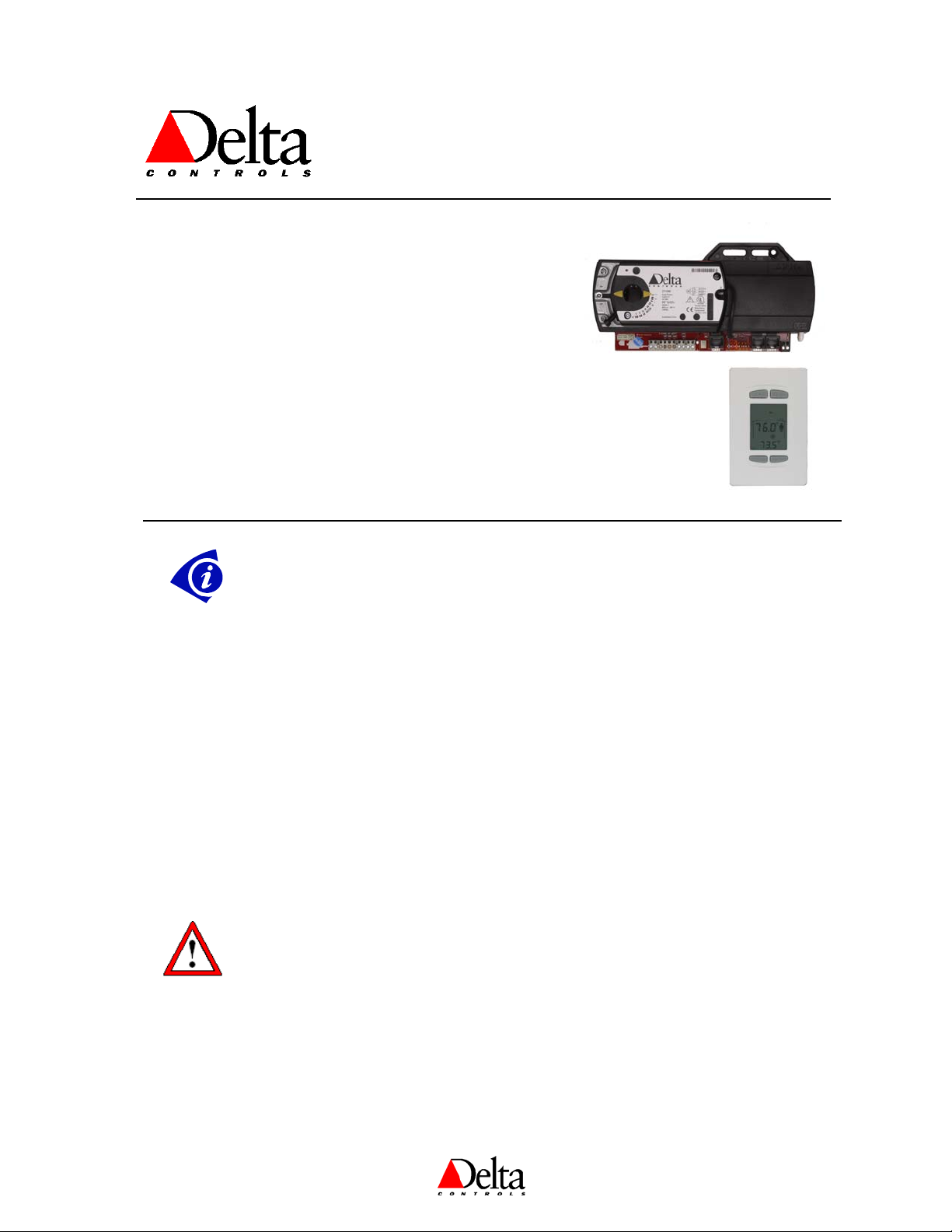
The Delta VAV Termination (DZNT) solution consists of an
intelligent LCD thermostat (DZNT-T0-VAV) and remote
termination board (DZTM) for mounting on the VAV/VVT unit.
The thermostat has an LCD display, four pushbuttons for setpoint
and occupancy override, and contains a variety of configurable
VAV/VVT algorithms suitable for controlling all three remote
termination board types.
Every remote termination board comes complete with a damper
actuator, flow sensor for VAV models, and housing. They are also
capable of fan control, reheat control and automatic heat/cool
changeover.
Important Information
1. The Termination Board mounted to the VAV/VVT box is not a programmable
controller. All control and network functions are performed by the DZNT-T0VAV.
2. DZNT-T0-VAVs may be part of an MS/TP network or stand-alone. However, a
stand-alone DZNT-T0-VAV does not have a time clock or scheduling functions.
Occupied and Unoccupied periods are determined by airflow or a BAS contact
closure on IP3.
3. DZNT-T0-VAV used for VAV / VVT termination may not be used on LINKnet
networks.
4. Data exchange may be done in GCL programming in any DCU or Application
Controller on the MS/TP network.
5. Because of the fixed objects in the controller, alarming and trending must be
carried out by different controller on the network. Be aware that large numbers of
DER objects will affect the Scan Rate of those controllers. If the requirements call
for trending or alarming, it is recommended that you limit the number of DZNT
VAV devices so a maximum of 200 DER objects are created on any one system
panel.
VVT: DZNT-104D | DZNT-104T | DZNT-112A
VAV / VVT Termination:
Document Edition 1.2
Cautions or Warnings: This graphic identifies a situation where damage to a
device will occur if the instructions are not followed carefully. To protect the
Document Edition 1.2 Page 1 of 16
equipment that you are using, please read and follow the instructions in these notes.
Package Contents
Product: VAV: DZNT-V104D | DZNT-V104T | DZNT-V112A
VVT: DZNT-104D | DZNT-104T | DZNT-112A
DZNT VAV/VVT Installation Guide
DZNT VAV / VVT Installation Guide
0
Related Documents
DZNT VAV Application Guide: (configuration & programming)
Delta Controls Wiring Guidelines
Related Documents – Cont.
ORCAview Operator Guide
ORCAview Technical Reference Manual
Release Notes for related Firmware and DZNT-T0-VAV products
Actuator Instructions
Warning: Do not open the actuator or the controller.
Note: Place the actuator/product on the damper shaft so that the front side, (label)
The Actuator/Product can be used with 3/8, 1/2, and 5/8 inch damper shaft sizes
• A 3/8-inch shaft size adapter is provided. Remove the 1/2-inch shaft size guide, and then install the shaft
insert so that the raised tabs are inserted last, through the damper shaft hole on bottom of product.
• A 1/2-inch shaft size guide is factory installed. If the damper shaft size is not 1/2 inch, then remove the
shaft guide from actuator through the damper shaft hole on bottom of product.
of the actuator/product is accessible.
• For 5/8-inch shaft size, remove any shaft guides or adapters from the actuator through the damper shaft
hole on bottom of product.
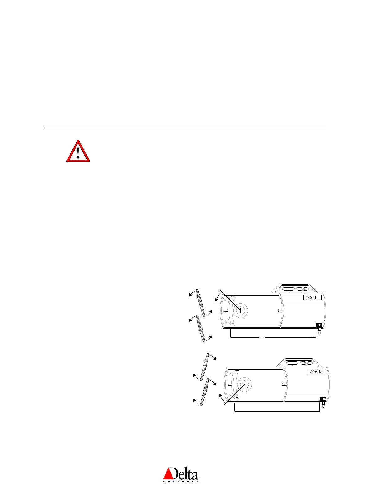
Set the Actuator to Open Clockwise or Counter Clockwise
1. Determine whether the damper blades will
rotate clockwise or counter clockwise to open.
2. Remove power, if connected.
Counter Clockwise
to open
3. Slide the manual override switch to manual
and move the adjustment lever to the position
as indicated by the drawing. Return the switch
to automatic.
4. Tighten 3mm allen-screw on to damper shaft,
torque 55-60 lb-in (6.5-7 Nm).
5. Restore power.
Clockwise
6. Use the DZNT-T0-VAV to set the damper
to open
action to Direct (CW) or Reverse (CCW).
7. Once power is restored, the actuator returns to
automated control.
0
Page 2 of 16 Document Edition 1.2
Delta Controls
eve
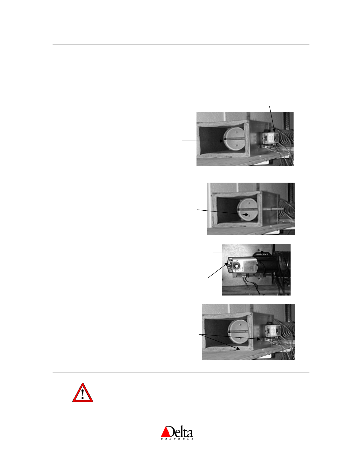
Mounting the VAV Termination Board
The actuator on one end of the housing fits over the damper shaft on the VAV box. The other end of the
plastic housing is secured to the VAV box with a sheet metal screw (through the mounting slots and brass
bushing provided). It is recommended that the screw be positioned near the center of the slot (triangle mark in
the plastic). After positioning the damper and the actuator to accommodate proper movement, the actuator
bracket is tightened securely.
Steps to mounting the VAV
1. According to the Damper Shaft sizes as
indicated above, ensure that the shaft insert
is correct for the size of the damper shaft.
2. Determine whether the damper will rotate
clockwise or counterclockwise to open.
3. Ensure that the damper is fully closed. The
indicator on the end of the damper shaft
should be vertical (up-down).
Open
Damper
Damper Shaft
4. Slide the controller over the damper shaft.
5. Secure the right end of the plastic housing
to the VAV box with a sheet metal screw
(through the mounting slots and brass
bushing provided). It is recommended that
the screw be positioned near the center of
the slot (triangle mark in the plastic).
6. Move the actuator clamp to the fully closed
position. If the damper rotates clockwise to
open, slide the manual override switch to
manual, and move the adjustment lever to
the far left. Return the switch to automatic.
7. Confirm again that the damper is fully
closed.
8. Tighten the adjustment lever. (3mm allen-
screw, onto the damper shaft, torque 55 60 lb-in (6.5-7 Nm)).
9. To ensure proper functionality of the
damper, depress the clutch, and stroke the
damper fully in both directions.
Closed
Damper
Position for sheet
metal screw
Adjustment
L
r
VAV mounted
on
Closed
Damper
Warnings and Cautions
Personal injury/loss of life may occur if a procedure is not performed as specified.
Equipment damage or loss of data may occur if the user does not follow a
procedure as specified.
Document Edition 1.2 Page 3 of 16
DZNT VAV / VVT Installation Guide
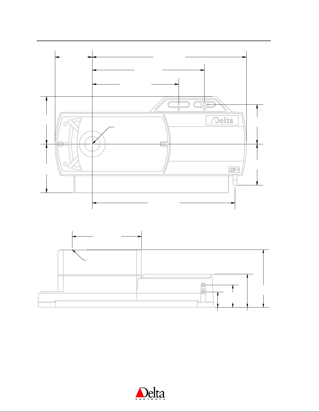
Mounting Dimensions
1.83 Inch
46.3 mm
4.23 Inch
107.5 mm
7.54 Inch
191.5 mm
5.50 Inch
139.5 mm
2.32 Inch
58.9 mm
2.39 Inch
60.6 mm
Damper Shaft
1.93 Inch
49.0 mm
2.02 Inch
51.3 mm
6.99 Inch
3.70 Inch
94.0 mm
Damper Shaft
177.5 mm
3.20 Inch
81.1 mm
31.4 mm
1.84 Inch
46.5 mm
1.25 Inch
0.85 Inch
21.5 mm
Page 4 of 16 Document Edition 1.2
Delta Controls
Mounting the Thermostat
The DZNT-T0-VAV backplate is designed for mounting directly on a standard North American, European or
Australian electrical box, but may be mounted in other ways as well.
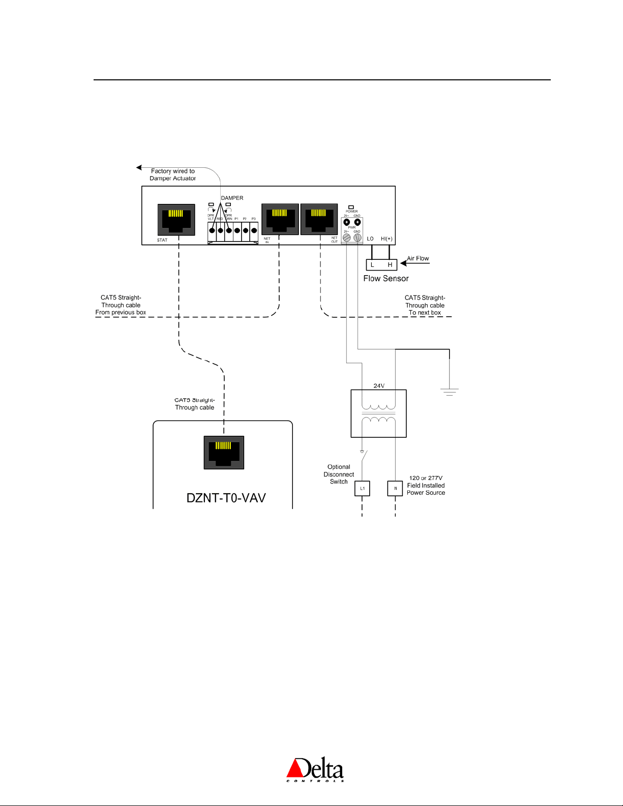
Wiring Diagram – Thermostat / Termination Board Connections
For further wiring details regarding reheat and other applications see the DZNT VAV/VVT Application Guide.
Notes:
1. Ensure you use straight-through Cat3 or higher (Cat5, Cat5e, Cat6) cables to join boxes. Although
Cat5 is mentioned throughout the documentation, any of these cable types are acceptable.
2. Although it is not necessary to go from NET OUT on one box to NET IN on the next, doing so will
likely give the most even distribution of devices on the network and allow for easier troubleshooting
of network problems.
3. At the last box on each trunk, keep the loop-back connector, ADP45-MSTP-LOOP, in place on the
NET OUT connector. Doing so will provide improved network stability and allow any one device to
be removed from the network without causing a loss of communications to the devices downstream
4. If the same power source is used for more than one device, ensure that the transformer is properly
sized for the rated VA and ensure that the same polarity is observed from device to device.
Document Edition 1.2 Page 5 of 16
 Loading...