

Delta VFD055VL23A-J, VFD220VL43A-J, VFD150VL43A-J, VFD075VL23A-J, VFD300VL43A-J User Manual
...Page 1
Page 2
9-(
Page 3

Page 4
Preface
Thank you for choosing Delta’s high-performance Hybrid servo drive VFD-VJ Series
dedicated to plastic injection molding machine. The VFD-VJ series products are made of
high quality components and materials that incorporate the latest microcontroller
technology.
This manual is to be used for the installation, parameter setting, troubleshooting, and daily
maintenance of the Hybrid servo drive. To guarantee safe operation of the equipment, read
the following safety g uideli nes be fore conn ecti ng pow er to the Hy bri d serv o driv e. Keep this
operating manual at hand and distr ibute to all users for reference.
To ensure the safety of operators and equipment, only qualified personnel familiar with
Hybrid servo drive are to do installation, start-up and maintenance. Always read this
manual thoroughly before using VFD-VJ series Hybrid Servo Drive, especially the
WARNING, DANGER and CAUTION notes. Failure to comply may result in personal injury
and equipment damage. If you have any questions, please contact your dealer.
Firmware version: V2.03
PLEASE READ PRIOR TO INSTALLATION FOR SAFETY.
; AC input power must be disconnected before any wiring to the Hybrid
servo drive is made.
; Even if the power has been turned off, a charge may still remain in the
DANGER
DC-link capacitors with hazardous voltages before the POWER LED is
OFF. Please do not touch the internal circuit and components. For safe
maintenance, use a multimeter to measure the voltage across the +1
and – terminals. The measured value should be lower than 25Vdc for the
system to operate normally.
; There are highly sensitive MOS components on the printed circuit boards.
These components are especially sensitive to static electricity. Please do
not touch these components or the circuit boards before taking anti-static
measures. Never reassemble internal components or wiring.
; Ground the Hybrid servo drive using the ground terminal. The grounding
method must comply with the laws of the country where the AC motor
drive is to be installed.
; This series of product s is used to c ontrol the t hree-ph ase in ductio n mot ors
and permanent magnet synchronous motors. It cannot be used for
single-phase motors or for other purposes.
; This series of products cannot be used on occasions that may endanger
personal safety.
; Please prevent children or unauthorized personnel from approaching the
Hybrid servo drive.
Page 5
; Never connect the Hybrid servo drive output terminals U/T1, V/T2 and
W/T3 directly to the AC mains circuit power supply.
; DO NOT use Hi-pot test for internal components. The semi-conductor
used in Hybrid servo drive easily damage by high-voltage.
; Even if the 3-phase AC motor is stop, a charge may still remain in the
main circuit terminals of the AC motor drive with hazardous voltages.
; Only qualified persons are allowed to install, wire and maintain AC motor
drives.
; When the Hybrid servo drive uses an external terminal as its source of
operation commands, the motor may start running immediately after the
power is supplied. In this case, it may be dangerous to any on-site
personnel.
; DO NOT install the Hybrid servo drive in a place subjected to high
temperature, direct sunlight, high humidity, excessive vibration, corrosive
gases or liquids, or airborne dust or metallic particles.
; Only use Hybrid servo drives within specification. Failure to comply may result in
fire, explosion or electric shock.
;
When the motor cable between Hybrid servo drive and motor is too long,
the layer insulation of the motor may be damaged. Please add an AC
output reactor to prevent damage to the motor. Ref e r to appendix A
Reactor for details.
; The rated voltage for Hybrid servo drive must be ≤ 240V (≤ 480V for 460V
models) and the mains supply current capacity must be ≤ 5000A RMS
(≤10000A RMS for the ≥ 40hp (30kW) models).
NOTE
The content of this manual may be revised without prior notice. Please consult our distributors or download the most
updated version at http://www.delta.com.tw/industrialautomation
Page 6

Table of Contents
1. Use and Installation
1-1 Receiving and Inspection 1-2
1-2 Product Specifications 1-3
1-3 Selection of Hybrid Servo Drives and Motors 1-4
1-4 Product Installation 1-6
1-5 Product Dimensions 1-11
2. Wiring
2-1 Description of Wiring 2-2
2-2 Description of Terminals on Main Circuit 2-7
2-3 Description of Terminals on Control Circuit 2-11
3. Machine Adjustment Procedure
3-1 Description of Control Panel 3-2
3-2 Machine Adjustment Procedure 3-4
4. Description of Parameters
4-1 Summary of Parameters 4-2
4-2 Detailed Description of Parameters 4-9
5. Fault Diagnostic Methods
5-1 Error Messages 5-2
5-2 Over Current OC
5-3 Ground Fault Factor GFF
5-4 Over Voltage OV 5-8
5-5 Low Voltage Lv 5-8
5-6 Over Heat OH1 5-9
5-7 Overload OL 5-9
5-8 Phase Loss PHL 5-10
5-9 Electromagnetic/Induction Noise 5-11
5-7
5-7
5-10 Environmental Condition 5-12
6. Suggestions and Error Corrections for Hybrid Servo Drives
6-1 Maintenance and Inspecti ons 6-2
Page 7

6-2 Greasy Dirt Problem 6-2
6-3 Fiber Dust Problem 6-5
6-4 Erosion Problem 6-6
6-5 Industrial Dust Problem 6-7
6-6 Wiring and Installation Problem 6-8
6-7 Multi-function Input/Output Terminals Problem 6-9
7. Recommended Operations for Customers and Troubleshooting
7-1 Regular Maintenance and Check 7-2
7-2 Oil Contamination 7-6
7-3 Lint Issue 7-7
7-4 Corrosion Issue 7-9
7-5 Dust Issue 7-10
7-6 Installation and Wiring/Connection Issue 7-11
7-7 Multi-function Input/Output Terminal Application Issue 7-12
Appendix A Optional Accessories
A-1 Braking Resistor Sele ction Chart A-2
A-2 Non-fuse Circuit Breaker A-6
A-3 Fuse Specification A-6
A-4 Reactor A-7
A-4-1 AC Input Reactor Recommended Value A-7
A-4-2 AC Output Reactor Recommended Va lue A-7
A-4-3 Zero Phase Reactor A-9
A-4-4 DC Reactor A-10
A-5 Digital Keypad KPV-CE01 A-11
A-6 Speed Feedback PG Card Selection A-15
A-7 Communication Card A-19
A-8 EMI Filter A-20
Page 8
1. Use and Installation
1. Description of Hybrid Servo Drives
1-1 Receiving and Inspection
1-2 Product Specifications
1-3 Overview of Hybrid Servo Systems
1-4 Product Installation
1-5 Product Dimensions
The Hybrid servo drive should be kept in the shipping carton or crate before installation. In order to retain
the warranty coverage, the Hybrid servo drive should be stored properly when it is not to be used for an
extended period of time. Storage conditions are:
; Store in a clean and dry location free from direct sunlight or corrosive fumes.
; Store within an ambient temperature range of -20
; Store within a relative humidity range of 0% to 90% and non-condensing
environment.
; Avoid storing the product in an environment containing corrosive gases and liquids.
; DO NOT place on the ground directly. It should be stored properly. Moreover, if the
surrounding environment is humid, you should put exsiccator in the package.
; DO NOT store in an area with rapid changes in temperature. It may cause
condensation and frost.
; If the Hybrid servo drive is stored for more than 3 months, the temperature should
not be higher than 30 °C. Storage longer than one year is not recommended, it could
result in the degradation of the electrolytic capacitors.
; When the Hybrid servo drive is not used for longer time after installation on building
sites or places with humidity and dust, it’s best to move the Hybrid servo drive to an
environment as stated above.
°
C to +60 °C.
1-1
Page 9
1-1 Receiving and Inspection
This VFD-VJ Hybrid servo drive has gone through rigorous quality control tests at the factory before
shipment. After receiving the Hybrid servo drive, please check for the following:
; Inspect the unit to assure it was not damaged during shipment.
; Make sure that the part number indicated on the nameplate corresponds with the part number of
your order.
If the registered information does not match your purchase order, or if the product has any problem,
please contact the dealer or distributor.
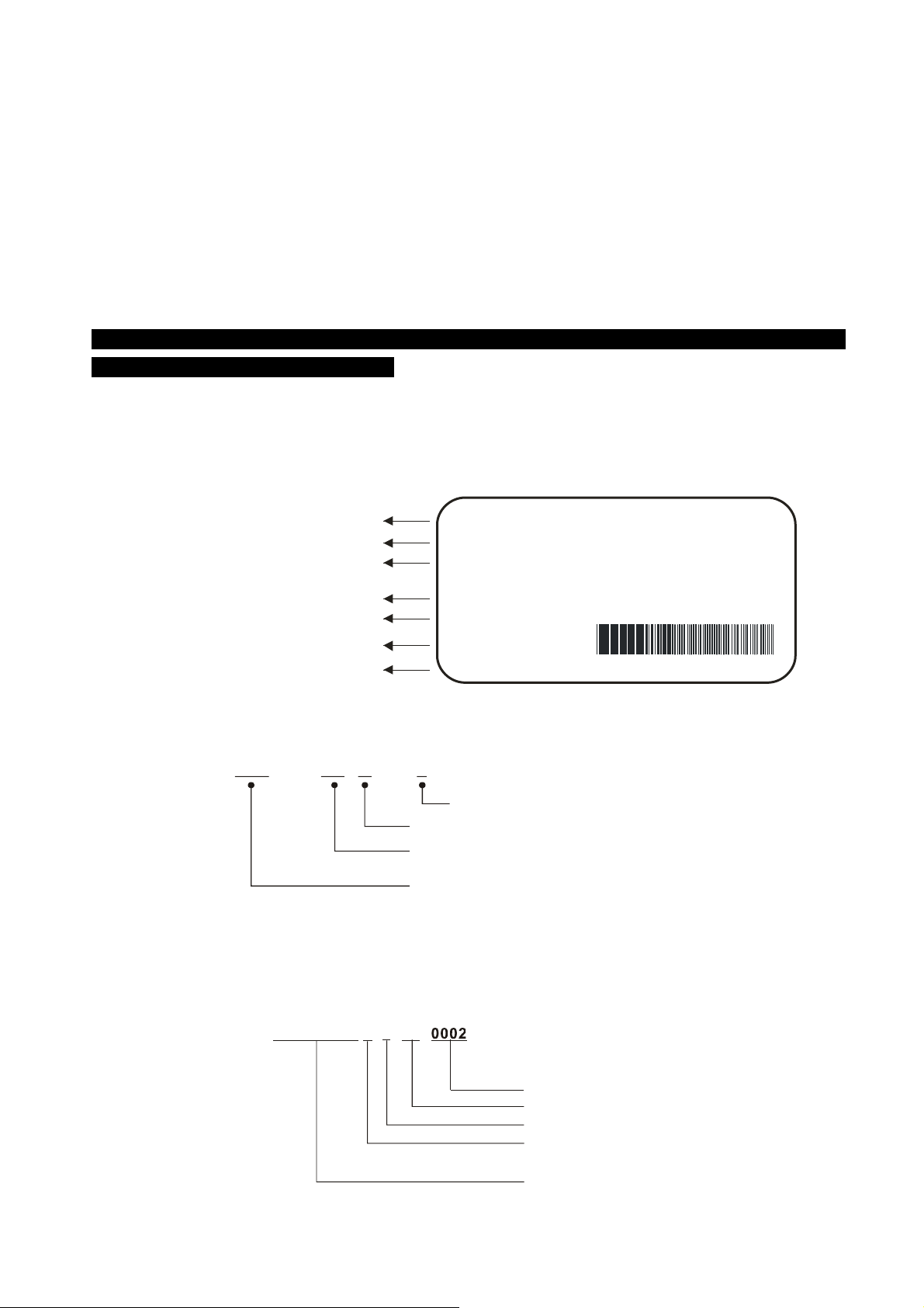
Nameplate Information
Let us take the 15HP/11kW 230V 3-Phase model as an example.
AC Driv e Mode l
Input Spec.
Out put Spec.
Output Frequency Range
Software version
Bar Co de
Seri al Number
Model Explanation
VFD VL - 110 23 A J
MODEL
INPUT
OUTPUT
: V FD110V L23A -J
: 3PH 180-264V 50/60Hz 43A
: 3PH 0-230V 41.1A
11kW/15HP
Freq. Range
: 0~600Hz
Version: 1.00
110VL23AJT9310002
Delta's high-performance H ybrid servo drive
Version Type
MainsInput Voltage
Applicable motor capacity
055:7.5HP(5.5kW)
075:10HP (7 .5k W)
110:15HP(11kW)
150:20HP(15kW)
23: 230V 3-PHASE
43:460V 3-PHASE
185:25HP (1 8.5k W)
220:30H P(2 2kW )
300:40H P(3 0kW )
370:50HP(37kW)
450:60HP(45kW)
550:75HP(55kW)
750:100 HP (75k W)
Series Number Explanation
230V 3-phase 15HP(11kW)
319 T110VL23AJ
Production numbe r
Production week
Production year 2009
Production facto ry
(T: Taoyuan, W: Wujian)
Model
1-2
Page 10
1. Use and Installation
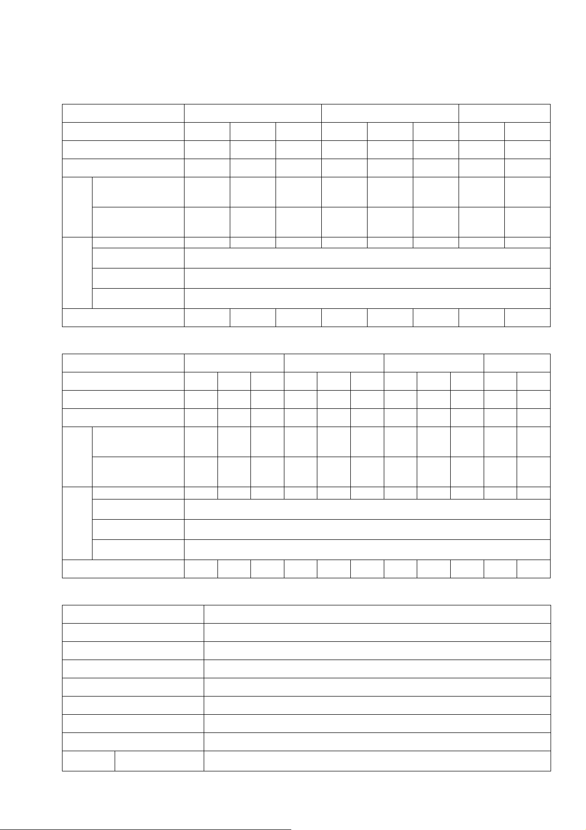
1-2 Product Specifications
Specifications of 230V Series
Frame No. C D E2
Model No. VFD-_ _VL_ _A-J 055 075 110 150 185 220 300 370
Power (KW) 5.5 7.5 11 15 18.5 22 30 37
Horse Power (HP) 7.5 10 15 20 25 30 40 50
Output Current for
Output
Power
Supply
Continuous Operation
Over 60 sec (A)
Output Current for
Continuous Operation
Over 20 sec (A)
Input Current (A)
Tolerable Input
Voltage Variation
Tolerable Supply
Voltage Variation
Tolerable Supply
Frequency Variation
Weight (kg) 8 10 10 13 13 13 36 36
33 46 62 90 119 119 180 248
37 54 70 106 140 140 204 292
25 31 47 60 80 90 106 126
Three-phase 200~240V 50/60Hz
±10% (180~264V)
±5% (47~63Hz)
Specifications of 460V Series
Frame No. C D E1 E2
Model No. VFD-_ _VL_ _A-J 055 075 110 150 185 220 300 370 450 550 750
Power (KW) 5.5 7.5 11 15 18.5 22 30 37 45 55 75
Horse Power (HP) 7.5 10 15 20 25 30 40 50 60 75 100
Output Current for
Output
Power
Supply
Continuous Operation
Over 60 sec (A)
Output Current for
Continuous Operation
Over 20 sec (A)
Input Current (A)
Tolerable Input
Voltage Variation
Tolerable Supply
Voltage Variation
Tolerable Supply
Frequency Variation
Weight (kg) 8 10 10 13 13 13 36 36 36 50 50
21 27 36 46 58 62 102 124 155 187 255
25 32 42 54 68 78 120 146 182 220 300
14 18 24 31 39 47 56 67 87 101 122
Three-phase 380~480V, 50/60Hz
±10% (342~528V)
±5% (47~63Hz)
Common Features
Control method SVPWM
Speed Detector Resolver / Incremental Encoder
Speed Command Input DC 0~10V, 3-point calibration of analog input is supported
Pressure Command Input DC 0~10V, 3-point calibration of analog input is supported
Pressure Feedback Input DC 0~10V
General Purpose Input Signal 5 ch DC24V 8mA
General Purpose Output Signal 2 ch DC24V 50mA, 1 ch Relay output
Analog Output Voltage 1 ch dc 0~10V
Optional
Peripheral
Speed Feedback PG
Card
Mandatory (Refer to Appendix A-5)
1-3
Page 11
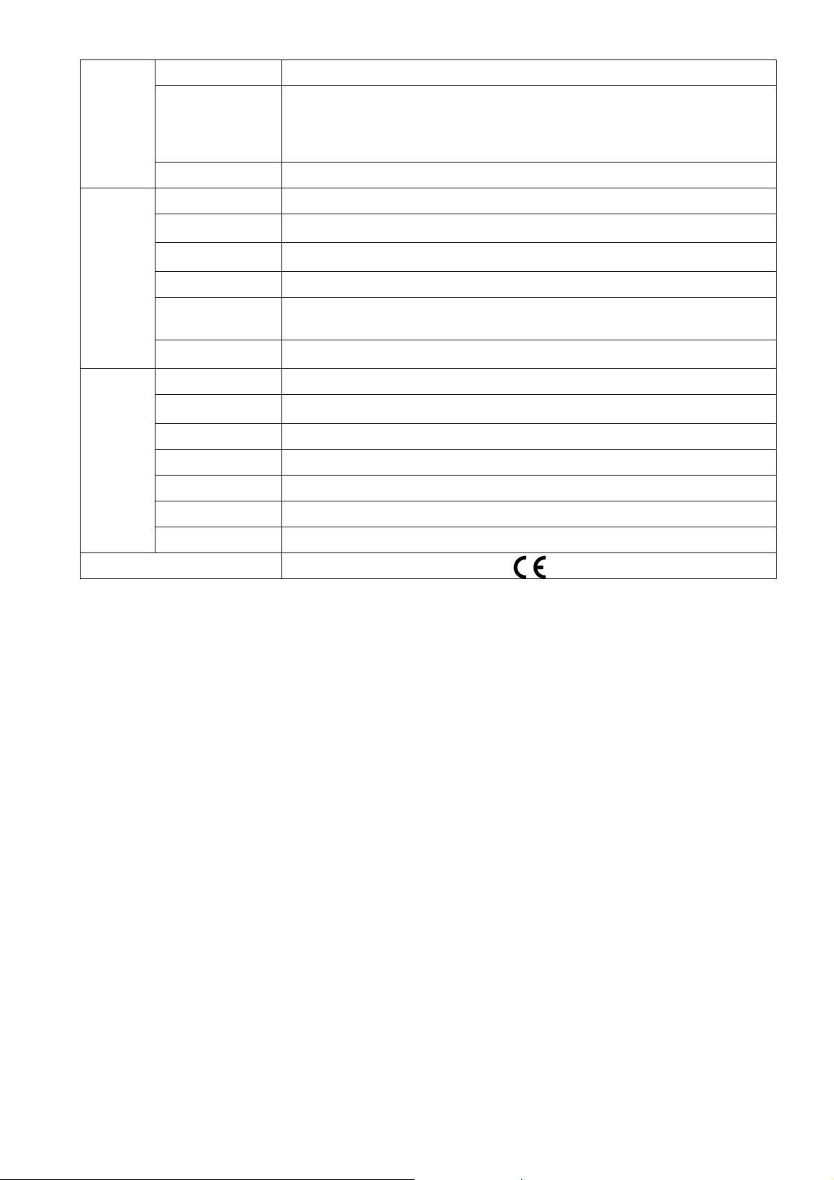
Accessories
Braking Resistor Mandatory (Refer to Appendix A-1)
Mandatory (It must has an output signal ranging within 0~10V, which can be configured
Protection
Feature
Environment
Pressure Sensor
EMI Filter
Motor Protection
Over Current
Protection
Ground Leakage
Current Protection
Voltage Protection
Input Power Supply
Over Voltage
Protection
Over Temperature
Protection
Protection Level
Operation
Temperature
Storage Temperature
Humidity
Vibration
Cooling System
Optional (Refer to Appendix A-7)
by Parameters 03-10~03-11;
The maximum pressure can be configured by Parameter 00-08)
Electronic thermal relay protection
Over current protection is activated at 300% of the rated current
Activated when the leakage current is higher than 50% of the drive’s rated current
Over Voltage Level: Vdc>400/800 V; Low Voltage Level: Vdc<200/400 V
Metal Oxide Varistor (MOV)
Built-in temperature sensor
NEMA 1/IP20
-10°C~45°C
-20°C~60°C
Below 90% RH (non-condensing)
1.0G below 20Hz, 0,6G at 20~60 Hz
Forced air cooling
Installation Altitude
International Certification
Altitude below 1,000m, keep from corrosive gasses, liquid and dust
1-4
Page 12
1. Use and Installation
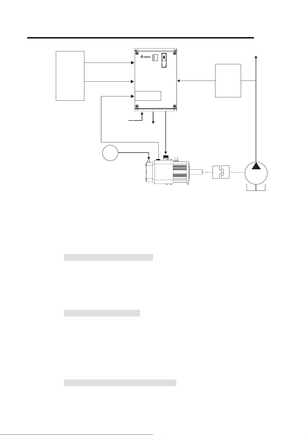
1-3 Overview of Hybrid Servo Systems
Pressure Command
(0~10V)
Injector
Contr ol l e r
Flow Rate Command
(0~10V)
RST
Power
Terminal
Encoder signal
AC
FAN
220V/380V
Del t a Hybrid
Servo
Dri v e
PG Card
U V W
Brake resistance/
Brake Unit
Pressur e
Feedback
(0~10V)
Pressu r e
Sensor
1-3-1 Selection of Hybrid Servo Drives and Motors
Due to the differences in the hydraulic system in practical applications, the following choice of
drives and motors is provided as a reference.
In the following example, a flow of 64L/min and maximum holding pressure of 175Bar are
used.
Oil
Pump
1. Pump Displacement per Revolution
Based on the maximum flow of the system (L/min), the pump displacement per revolution
(cc/rev) can be calculated.
Example: If the maximum flow of the system is 64L/min and the highest rotation speed of
the motor is 2000rpm, the displacement per revolution is 64/2000*1000 = 32
cc/rev.
2. Maximum Torque of the Motor
Based on the maximum pressure (Mpa) and pump displacement per revolution (cc/rev),
the maximum torque can be calculated.
Example: For the required maximum pressure of 17.5 Mpa and pump displacement per
revolution of 32cc/rev
Torque = 17.5*32*1.3/(2*pi) = 116 N-m, where the factor 1.3 is used to compensate the
total loss in the system.
3. Rated Torque and Rated Power of the Motor
At the maximum pressure for the holding pressure, the required torque should be 1.5
times of the motor’s rated torque or less (depending on the data provided by the motor’s
1-5
Page 13

manufacturer). Over such an operating condition, the over-temperature of the motor may
π
ω
−
=
easily occur. Let u s take the factor 1.5 as an example, i f the rated to rque of the motor is 77
N-m, the motor with a power of 12kW* and a rated speed of 1500 rpm can be chosen.
*The power of the motor is calculated by using
××
rpmmNTWP
)60/2()()(
4. Maximum Current of the Motor
Example: Check the parameter kt (Torque/A) in the motor’s specifications, if kt = 3.37, the
maximum current is approximately 116/3.37 = 34A at the maximum torque of
116 N-m.
5. Selection of Matched Hybrid Servo Drive
Example: Look up the over-load capability for each Hybrid servo drive in the product
specification chart
If the holding pressure is at the maximum pressure of 17.5 Mpa, and a pump of
32cc/rev is used, the required motor current is approximately 34A
For such a current value, the following models can be chosen
VFD075VL43A-J, the overload may occur within 20 sec.
VFD110VL43A-J, the overload may occur approximately after 60 sec.
NOTE
If there is no suitable motor that meets the specifications, a motor with a higher rated value can be used instead.
For any information about the Hybrid servo drives or any assistance in detailed configuration of your company's
products, please contact the manufacturer.
1-3-2 Selection of Pump for Hybrid Servo Motor
Select a pump with a suitable displacement based on the required flow rate and motor speed;
If low noise is required, you can choose the screw pump or internal gear type.If a high
volumetric efficiency is required, you can choose the piston pump or dual displacement
piston pump.
Comparison of Commonly Used Pump (This may vary for different pump manufacturers).
Type of Oil Pump
Internal Gear Pump Low Medium Medium Low
Piston Pump High Low Low High
Screw Pump Medium High High Medium
Volumetric
Flow Pulsation Rotation Speed Noise
Efficiency
1-6
Page 14
1. Use and Installation
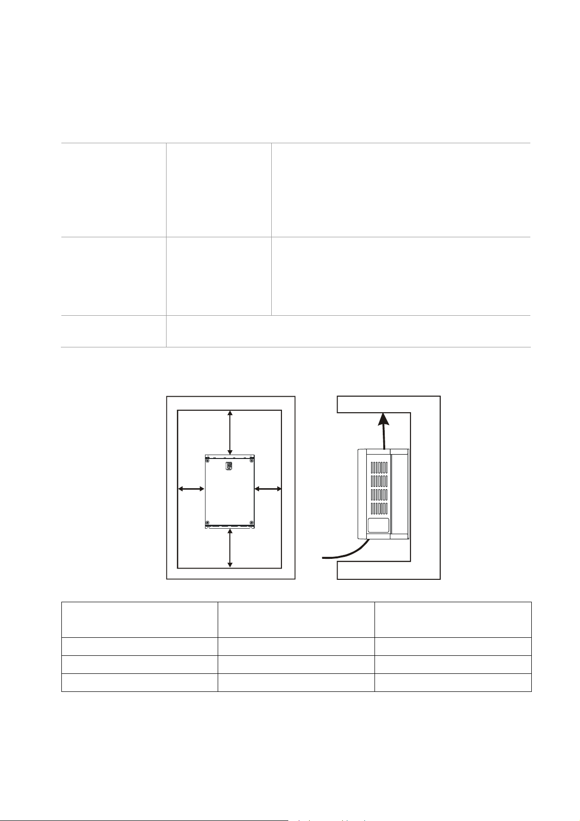
1-4 Product Installation
Please install the Hybrid servo drive under the following environmental conditions to ensure safety of
use:
Environmental
Condition for
Operation
Ambient temperature
Relative Humidity
Pressure
Installa tion Alti tude
Vibration
Environmental
Condition for Storage
and Transportation
Ambient temperature
Relative Humidity
Pressure
Vibration
Contamination
Level 2: Applicable to factory environment with low-to-medium contamination
Protection Level
Space for Installation
-10°C~ +45°C
<90% (non-condensing)
86 ~ 106 kPa
<1000m
<20Hz: 9.80 m/s
2
(1G) max; 20~50H:5.88 m/s2(0.6G)
max
-20°C~ +60°C (-4°F ~ 140°F)
<90% (non-condensing)
86 ~ 106 kPa
<20Hz: 9.80 m/s
2
(1G) max; 20 ~ 50Hz: 5.88 m/s
(0.6G) max
2
W
H
W
Air Flow
H
W
H
HP
mm (inch)
7.5-20HP
25-75HP
100HP
1. Mount the Hybrid servo drive vertically on a flat vertical surface object by screws. Other directions are
75 (3) 175 (7)
75 (3) 200 (8)
75 (3) 250 (10)
mm (inch)
not allowed.
2. The Hybrid servo drive will generate heat during operation. Allow sufficient space around the unit for
heat dissipation.
1-7
Page 15

3. The heat sink temperature may rise to 90°C when running. The material on which the Hybrid servo
drive is mounted must be noncombustible and be able to withstand this high temperature.
4. When Hybrid servo drive is installed in a confined space (e.g. cabinet), the surrounding temperature
must be within -10 ~ 40°C with good ventilation. DO NOT install the Hybrid servo drive in a space with
bad ventilation.
5. When installing multiple Hybrid servo drives in the same cabinet, they should be adjacent in a row with
enough space in-between. When installing one Hybrid servo drive below another one, use a metal
separation between the Hybrid servo drives to prevent mutual heating.
; Prevent fiber particles, scraps of paper, saw dust, metal particles, etc. from adhering to the heat
sink.
1-8
Page 16
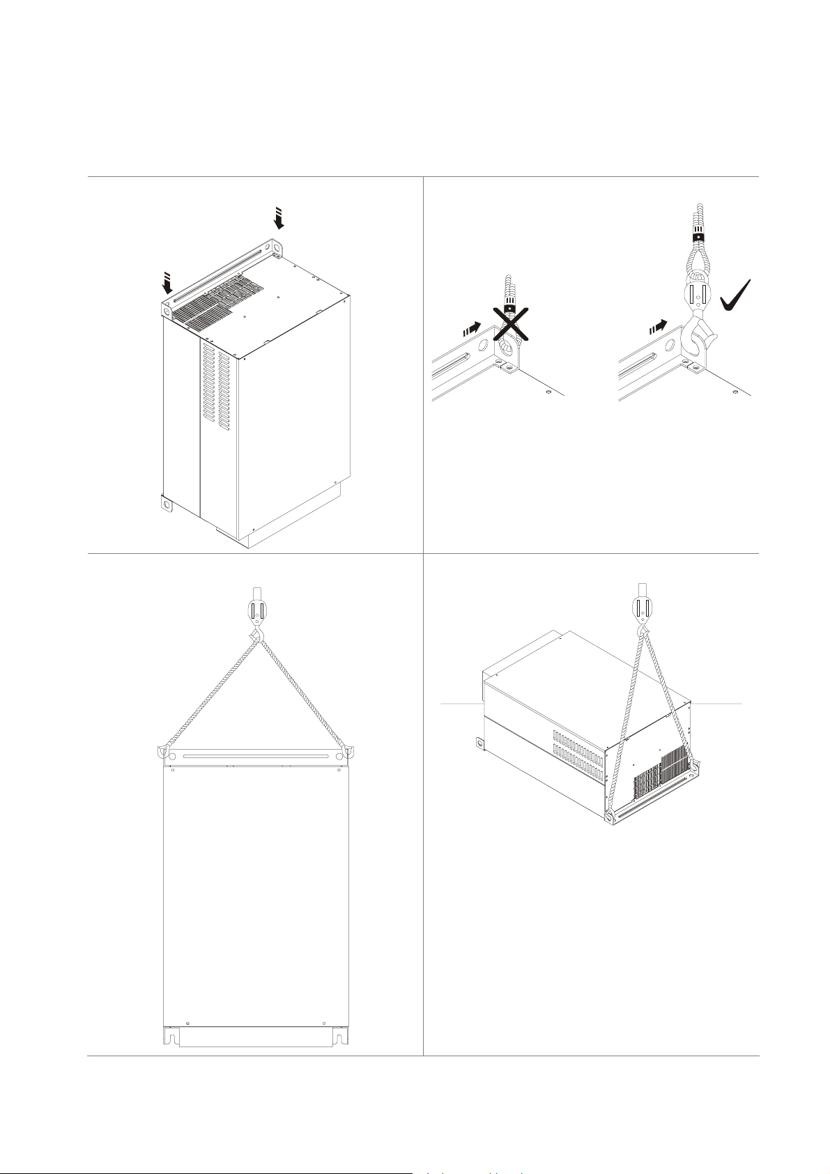
1. Use and Installation
Lifting
Please carry only fully assembled Hybrid servo drives as shown in the following. Lift the Hybrid servo
drive by hooking the lifting hole.
40-100HP (Frame No. E)
Step 1
Step 2
Step 3
Step 4
1-9
Page 17
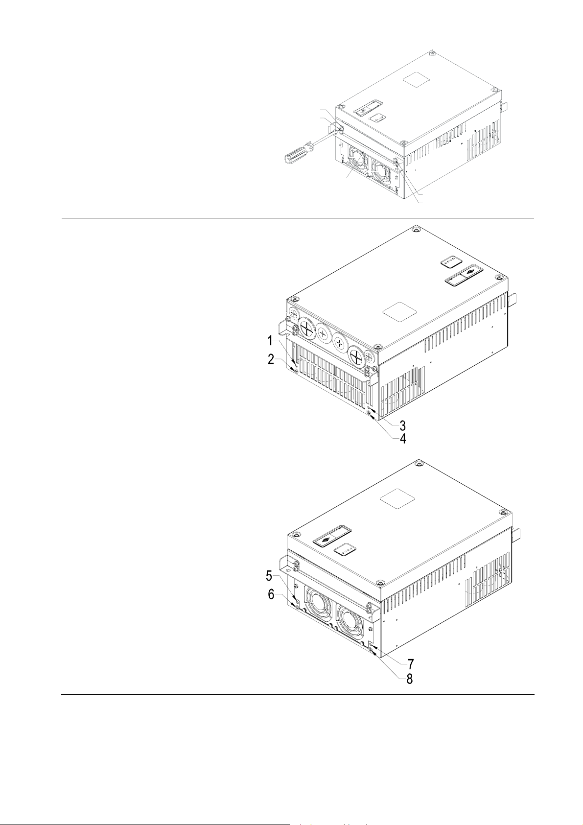
Flange Mounting
Step 1:
Please take out the 16 screws (8
screws for each top and bottom side of
the drive) and remove the fixed plate 1
and fixed plate 2) as shown in the
following figures.
1
2
5
6
fixed plate 1
1
2
5
6
fixed plate 2
3
4
7
8
3
4
7
8
Step 2:
place the 8 screws back in to secure
the fixed plate 1 and fixed plate 2 (as
shown in the following figures) with the
following torque.
Frame No. C: 14-17kgf-cm
[12.2-14.8in-lbf]
Frame No. D: 20-25kgf-cm
[17.4-21.7in-lbf]
Frame No. E: 20-25kgf-cm
[17.4-21.7in-lbf]
1
2
fixed plate 1
4
3
1-10
Page 18
1. Use and Installation
1
2
Step 3:
Please notice that it doesn’t need to
put those 8 screws shown in
the following figures back to
the drive. Moreover, please
make sure that these 2
different fixed plates are put in
the correct side as shown in
the figures.
fixed plate 2
3
4
1-11
Page 19
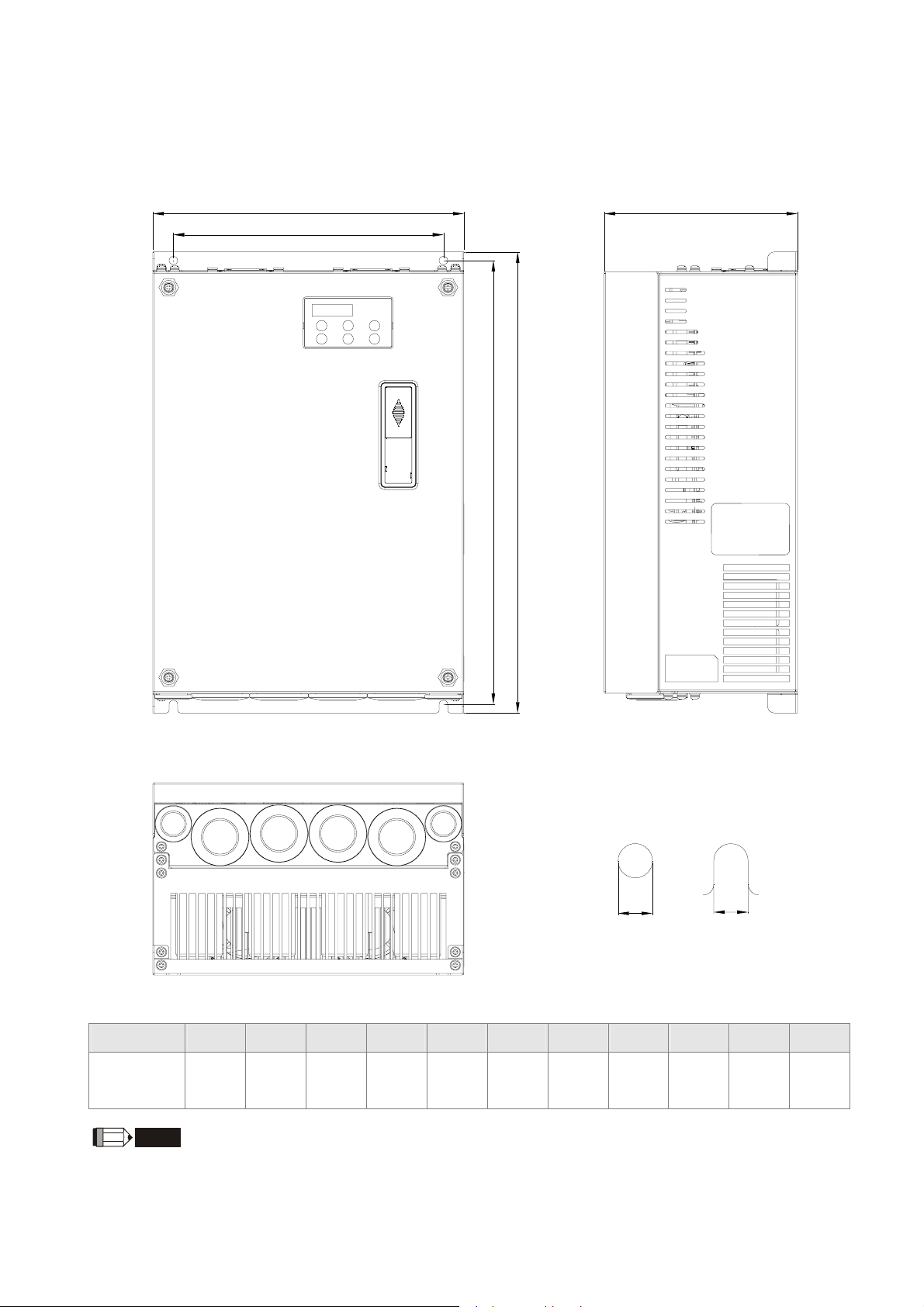
1-5 Product Dimensions
Frame No. C
W
W1
H1
D
H
S1
S1
Unit: mm [inch ]
Frame No. W W1 H H1 H2 H3 D Ø Ø1 Ø2 Ø3
C
235
[9.25]
NOTE
Frame No. C: VFD055VL23A/43A-J, VFD075VL23A/43A-J, VFD110VL23A/43A-J,
204
[8.03]
350
[13.78]
337
[13.27]
320
[12.60]
-
136
[5.35]
6.5
[0.26]
-
34
[1.34]
[0.87]
1-12
22
Page 20
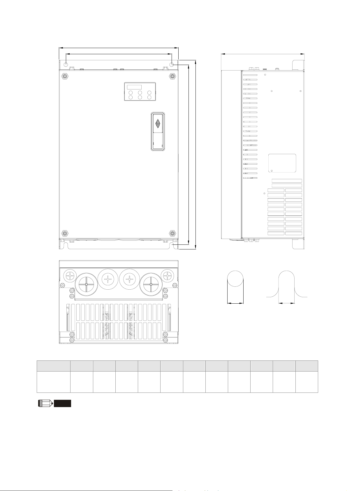
Frame No. D
W
H1
1. Use and Installation
DW1
H
S1S1
Unit: mm [inch ]
Frame No. W W1 H H1 H2 H3 D Ø Ø1 Ø2 Ø3
255.0
226.0
403.8
384.0
360.0
21.9
168.0
8.5
44
34
22
D
[10.04]
NOTE
Frame No. D: VFD150VL23A/43A-J, VFD185VL23A/43A-J, VFD220VL23A/43A-J,
[8.90]
[15.90]
[15.12]
[14.17]
[0.86]
[6.61]
[0.33]
[1.73]
[1.34]
[0.87]
1-13
Page 21
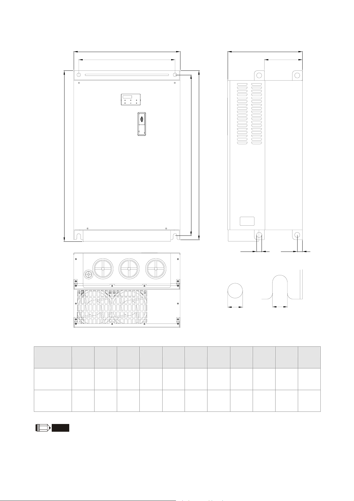
Frame No. E
W D
W1
D1
H
H2
H1
S1
S3
D2
S2
Unit: mm [inch ]
Frame No. W W1 H H1 H2 D D1: D2: S1 S2 S3
E1
370.0
[14.57]
370.0
335.0
[13.19]
335.0
-
595.0
589.0
[23.19]
589.0
560.0
[22.05]
560.0
260.0
[10.24]
260.0
132.5
[5.22]
132.5
18.0
[0.71]
18.0
13.0
[0.51]
13.0
13.0
[0.51]
13.0
[0.71]
E2
[14.57]
NOTE
Frame No. E1: VFD300VL43A-J, VFD370VL43A-J, VFD450VL43A-J,
Frame No. E2: VFD300VL23A-J, VFD370VL23A-J, VFD550VL43A-J, VFD750VL43A-J,
[13.19]
[23.43]
[23.19]
[22.05]
[10.24]
[5.22]
[0.71]
[0.51]
[0.51]
[0.71]
1-14
18.0
18.0
Page 22
2. Wiring
2. Wiring
2-1 Description of Wiring
2-2 Description of Terminals on Main Circuit
2-3 Description of Terminals on Control Circuit
After removing the front cover , check if the power and control terminals are clear. Be sure to observe the
following precautions when wiring.
; Make sure that power is only applied to the R/L1, S/L2, T/L3 terminals. Failure to comply may result in
damage to the equipments. The voltage and current should lie within the range as indicated on the
nameplate
; All the units must be grounded directly to a common ground terminal to prevent lightning strike or
electric shock.
; Please make sure to fasten the screw of the main circuit terminals to prevent sparks which is made by
the loose screws due to vibration
; It is crucial to turn off the Hybrid servo drive power before any wiring installation are
made. A charge may still remain in the DC bus capacitors with hazardous voltages even
if the power has been turned off therefore it is suggested for users to measure the
DANGER
remaining voltage before wiring. For your personnel safety, please do not perform any
wiring before the voltage drops to a safe level < 25 Vdc. Wiring installation with
remaining voltage condition may cause sparks and short circuit.
; Only qualified personnel familiar with Hybrid servo drives is allowed to perform
installation, wiring and commissioning. Make sure the power is turned off before wiring
to prevent electric shock.
; Make sure that power is only applied to the R/L1, S/L2, T/L3 terminals. Failure to
comply may result in damage to the equipment. The voltage and current should lie
within the range as indicated on the nameplate.
; Check following items after finishing the wiring:
1. Are all connections correct?
2. No loose wires?
3. No short-circuits between terminals or to ground?
2-1
Page 23
2-1 Description of Wiring
d
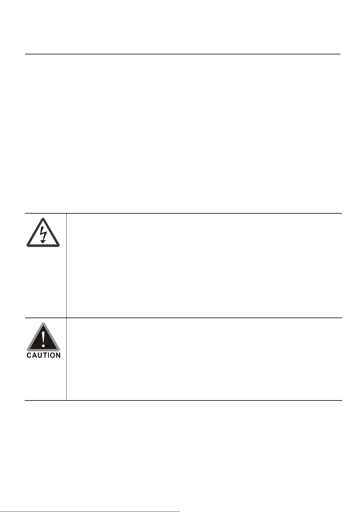
Users must connect wires according to the circuit diagrams on the following pages.
Standard wiring diagram of the VFD-VJ Hybrid servo drive in factory
Controller
Start Oil
Pump
Reset
r
o
t
a
c
i
d
n
I
n
o
i
t
c
n
u
f
l
a
M
Unused
Unused
Note 1*
+1
Output terminal
Brake Resistor (optional)
+2/B1
RA
RB
RC
MO1
MO2
MCM
input terminal
SON
RES
MI3
MI4
MI5
COM
B2
R
U
V
W
EMG
COM
+10V
AUI
ACM
-
L1
S
T
L2
L3
220V/380V
AC
FAN
e
U
V
M
3~
h
t
o
r
t
o
r
t
i
o
a
m
w
o
o
r
l
t
c
B
e
l
e
W
Note 3
*
Protection
switch for
electromotor
overheating
Note 4
*
R
Thermal
resistor
Pressure
Command
Flow Rate
Comman
Feedback
Signal
PI
ACM
QI
ACM
AFM
0~10Vdc/2mA
ACM
Set as output frequency
as manufactured
Note 2*
PG Card
14,16
13,15
+24V
ACM
PO
Resolver
R1
R2
5
4
7
9
S2
S4
S1
S3
+V
-V
output
Please use the
enclosed clips
Pressure Sensor
2-2
Page 24
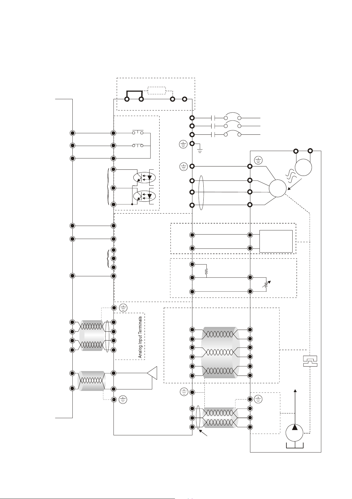
Note 1*
A
A
2. Wiring
pplicable to the models of 22kW or below
(including 22kW models with internal brake unit)
Brake resist or (optional)
-
+1
+2/B1
B2
Note 2*
EMVJ-PG01R/PG02R
PG Card
14,16
13,15
5
4
7
9
Resolver
R1
R2
S2
S4
S1
S3
pplicable to the models of 30kW or above
(including 30kW models with optional internal
brake unit)
+1
Brake Unit
VFDB
+-
+2
B1
Brake resistor
B2
-
EMVJ-PG01U
PG Card
14,16
13,15
5
4
7
9
10
2
Encoder
Vp
GND
A
A
B
B
Z
Z
Note 3*
If the motor’s temperature protection switches are normally close type, please set the Parameter 03-04 to 4 first,
and then carry out the wiring. In this case, the drive may display the EF1 error message. Just clear the message.
Note 4*
Please select the R value in accordance with the thermistor specifications. The related trigger level
can be configured by the Parameters 02-08 to 02-10. If the thermistor of Model Number KTY84 is
used, select the R value as 2k (1/4W) ± 0.1%, and set the Parameter 02-11 with the value of 1.
2-3
Page 25
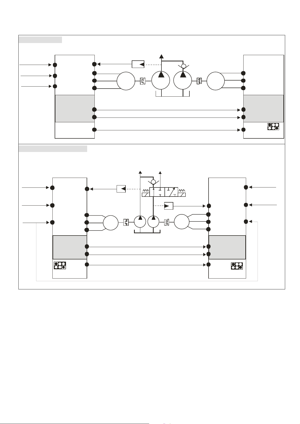
Multi-pump Operation Mode
r
e
Confluence Mode
Pressure
Command
Combine
Command
Hydraulic Pump
Activation
PI
QI
SON
PO
EMVJ-MF01
SG+
SG-
MO
Confluence-Diversion Mode
Master 1
Maste
Pressure
Command
Flow
Command
PI
PO
QI
U
V
W
Pressure
Feedback
Pressure
Feedback
*1
M
3~
Hydraulic
Outlet 1
*2
Operation Indication
Hydraulic
Outlet 2
*
2
Pressure
Feedback
M
3~
EMVJ-MF01
Master 2/ Slave
PI
PO
QI
Slav
U
V
W
SG+
SG-
SON
Pressure
Command
Flow
Command
IN.PWR.
SINK
*
3
MI
U
V
M
3~
M
3~
W
EMVJ-MF01
SG+
SG-
*
MO
IN.PWR.
SINK
*1 For firmware version 2.03 and above, the operating commands are given through the communications.
Therefore, the parameters for the slave is 01-01 = 2
*2 For firmware version 2.03 and above, it is not necessary to install this check valve. By selecting the slave
parameter 03-21 at the slave to see if the slave will perform the reverse depressurization. Parameters 03-21
= 0 for not performing the reverse depressurization.
*3 For firmware version 2.03 and above, the diversion/confluence signal is supplied to only Master 2/Slave. It is
not necessary to supply the signal to Master 1.For the following control arrangement, it is necessary to
disconnect the communications during diversion.
1
Operation Indication
Confluence/Diversion signals
U
V
MI
W
EMVJ-MF01
SG+
SG-
SON
IN.PWR.
SINK
2-4
Page 26
2. Wiring
i
t
- .
When the signals are confluence, the communication will be a short circuit
When the signals are diversion, the communication becomes an open circu
Pressure
Command
Flow
Command
PI
MI
Pressure
Command
Flow Command
Combined/Divert
Signals
SG+
SG-
PI
QI
Mater 1
03 13 1
-=
PO
M M
The wiring of main circuit and control circuit should be separated to prevent
;
SG+
SG-
Slave Slave
03 13 2
-=
Hydraulic outlet 1
SG+
Hydraulic outlet 2
03 13 2
-=
SG-
SG+
Mater 3
03 13 3
-=
M M
SG-
QI
PO
erroneous actions.
Please use shield wire for the control wiring and not to expose the peeled-off net in
;
front of the terminal.
Please use the shield wire or tube for the power wiring and ground the two ends of
;
the shield wire or tube.
Make sure that the leads are connected correctly and the AC drive is properly
;
grounded. (Ground resistance should not exceed 0.1Ω.)
Use ground leads that comply with local regulations and keep them as short as
;
possible.
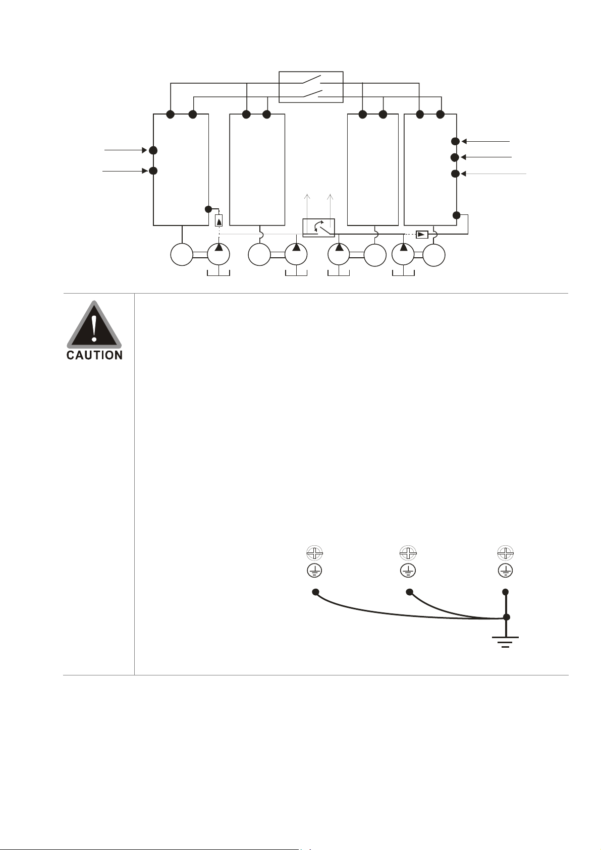
Multiple VFD-VJ units can be installed in one location. All the units should be
;
grounded directly to a common ground terminal, as shown in the figure below.
Ensure there are no ground loops.
Grounding terminals
Excellen
2-5
Page 27
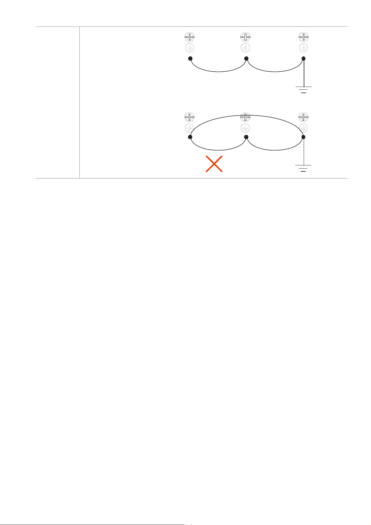
Grounding terminals
good
Grounding terminals
Not allowed
2-6
Page 28
2. Wiring
y
≤
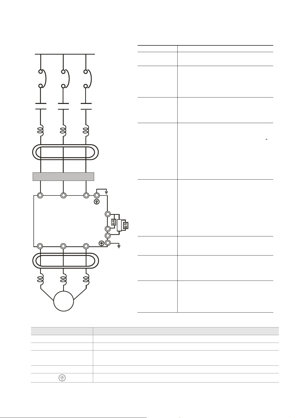
2-2 Description of Terminals on Main Circuit
Power Suppl
EMI Filter
R/L1 S/L2
U/T1 V/T2
Motor
T/L3
W/T3
FUSE/NFB
Magnetic
contactor
Input AC
Line Reactor
Zero-phase
Reactor
+/B1
B2
Output AC
Line Reactor
Br ake resi st er
-
Zero-phase
Reactor
Br ake Un it
VFDB
Items Explanations
Power supply
Fuse/NFB
(Optional)
Magnetic
contactor
(Optional)
Input AC Line
Reactor
(Optional)
Zero-phase
Reactor
(Ferrite Core
Common
Choke)
(Optional)
EMI filter
(Optional)
Brake Resistor
(Optional)
Output AC Line
Reactor
(Optional)
Please follow the specific power supply
requirements shown in Chapter 01.
There may be an inrush current during
power up. Please check the chart of
Appendix A-2 and select the correct
fuse with rated current. Use of an NFB
is optional.
Please do not use a Magnetic
contactor as the I/O switch of the AC
motor drive, as it will reduce the
operating life cycle of the AC drive.
Used to improve the input power factor,
to reduce harmonics and provide
protection from AC line disturbances.
(surges, switching spikes, short
interruptions, etc.). AC line reactor
should be installed when the power
supply capacity is 500kVA or more and
exceeds 6 times the inverter capacity,
or the mains wiring distance
10m.
Zero phase reactors are used to
reduce radio noise especially when
audio equipment is installed near the
inverter. Effective for noise reduction
on both the input and output sides.
Attenuation quality is good for a wide
range from AM band to 10MHz.
Appendix A specifies the zero phase
reactor. (RF220X00A)
To reduce electromagnetic
interference, please refer to Appendix
A for more details.
Used to reduce the deceleration time of
the motor. Please refer to the chart in
Appendix A for specific Brake
Resistors.
Motor surge voltage amplitude
depends on motor cable length. For
applications with long motor cable
(>20m), it is necessary to install a
reactor at the inverter output side.
Motor
Terminal Identification Description
R/L1, S/L2, T/L3 AC line input terminals 3-phase
U/T1, V/T2, W/T3 Output terminals of the Hybrid servo drive that are connected to the motor
+1, +2/B1
Connections for DC reactor to improve the power factor. It needs to remove
the jumper for installation. (DC reactor is built in for models ≧ 22KW)
+2/B1, B2 Connections for Brake Resistor (optional)
Earth connection, please comply with local regulations..
2-7
Page 29

Power supply input terminals for the main circuit:
Do not connect 3-phase model to one-phase power. R/L1, S/L2 and T/L3 has no
;
phase-sequence requirement, it can be used upon random selection..
It is recommend to add a magnetic contactor (MC) to the power input wiring to
;
cut off power quickly and reduce malfunction when activating the protection
function of the AC motor drive. Both ends of the MC should have an R-C surge
absorber.
Fasten the screws in the main circuit terminal to prevent sparks condition made
;
by the loose screws due to vibration.
Please use voltage and current within the specification.. Please refer to Chapter
;
1 for the specifications.
When using a general GFCI (Ground Fault Circuit Interrupter), select a current
;
sensor with sensitivity of 200mA or above and not less than 0.1-second
operation time to avoid nuisance tripping.
Please use the shield wire or tube for the power wiring and ground the two ends
;
of the shield wire or tube.
Output terminals for the main circuit:
When it needs to install the filter at the output side of terminals U/T1, V/T2, W/T3
;
on the Hybrid servo drive. Please use inductance filter. Do not use
phase-compensation capacitors or L-C (Inductance-Capacitance) or R-C
(Resistance-Capacitance), unless approved by Delta..
DO NOT connect phase-compensation capacitors or surge absorbers at the
;
output terminals of Hybrid servo drives.
The terminals of the DC reactor [+1, +2], terminals at DC side [+1, +2/B1]
This is the terminals used to connect the DC reactor to improve the power factor.
;
For the factory setting, it connects the short-circuit object. Please remove this
short-circuit object before connecting to the DC reactor.
DC react or
Jumper
+1
For those models without built-in brake resistor, please connect external brake
;
unit and brake resistor (both of them are optional) to increase brake torque.
DO NOT connect [+1, -], [+2, -], [+1/DC+, -/DC-] or brake resistor directly to
;
prevent drive damage.
2-8
Page 30
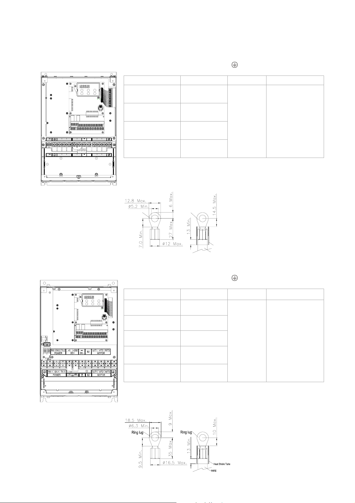
Specifications of the Terminals on the Main Circuit
2. Wiring
Frame No. C
/~ U/T1
+/~ R/L1 S/L2 T/L3B2+1
EPS
/~ U/T1 V/T2 W/T3
+/~ R/L1 S/L2 T/L3
EPS
+2/B1
DC+ DC-
POWER
+1
+2/B1
DC+
POWER MOTOR
Terminals on the main circuit:
R/L1, S/L2, T/L3, U/T1, V/T2, W/T3,
, +1, +2/B1, -, B2
Model Wire Diameter Torque Wire Type
VFD055VL23A-J
VFD110VL43A-J
VFD055VL43A-J
VFD075VL43A-J
VFD110VL23A-J
W/T3
V/T2
MOTOR
B2
DC-
VFD075VL23A-J
Wire Type: Stranded copper only, 75°C
The right figure below shows the specifications of the UL certified insulation heat
shrink tubing which can withstand 600V, YDPU2.
10-6 AWG.
(5.3-13.3mm
12-6 AWG.
(3.3-13.3mm
6 AWG.
(13.3mm
2
8-6 AWG.
(8.4-13.3mm
2
)
2
)
)
2
)
30kgf-cm
(26in-lbf)
Stranded copper
only,75°C
Ring lug
Ring lug
Frame No. D
Heat Shr ink Tube
WIRE
Terminals on the main circuit:
R/L1, S/L2, T/L3, U/T1, V/T2, W/T3,
, +1, +2, -
Model Wire Diameter Torque Wire Type
VFD150VL43A-J
VFD185VL43A-J
VFD150VL23A-J
VFD185VL23A-J
VFD220VL43A-J
VFD220VL23A-J
Wire Type: Stranded copper only, 75°C
The right figure below shows the specifications of the UL certified insulation heat
shrink tubing which can withstand 600V, YDPU2.
8-2 AWG.
(8.4-33.6mm
4-2 AWG.
(21.1-33.6mm
3-2 AWG.
(26.7-33.6mm
6-2AWG
(13.3-33.6mm
3-2AWG
(26.7-33.6mm
2
)
2
)
2
)
(43.4 lbf-in)
2
)
2
)
50Kgf-cm
Stranded copper
only,75°C
2-9
Page 31

Frame No. E
Terminals on the main circuit:
R/L1, S/L2, T/L3, U/T1, V/T2, W/T3,
, +1, +2, -
Model Wire Diameter Torque Wire Type
VFD300VL43A-J
VFD370VL43A-J
VFD450VL43A-J
VFD300VL23A-J
VFD370VL23A-J
VFD550VL43A-J
4-2 AWG.
(21.2-33.6mm
2
)
200kgf-cm
(173in-lbf)
57kgf-cm
(49in-lbf)
Stranded
copper
only,
75°C
VFD750VL43A-J
Wire Type: Stranded copper only, 75°C
2-10
Page 32

2. Wiring
A
2-3 Description of Terminals on Control Circuit
Description of SINK (NPN)/SOURCE (PNP) Mode Selection Terminals
1
Sink Mode
used with internal power (+24Vdc)
SON
EMG
RES
COM
3
Sink Mode
with external power
SON
EMG
+24V
2
Source Mode
used with internal power (+24Vdc)
SON
EMG
RES
COM
4
Source Mode
with external power
SON
EMG
+24V
RES
+
COM
external power +24V
The Position of External Terminals
RB
RA
RC
MCM
MO1
SON
MO2
+24V
EMG
RES
external power +24V
MI4
MI3
MI5
COM
+10V
RES
+
COM
Sink/Source
mode switch
PI ACMQI
AUI
FM
+24V
PO
DCM
ACM
+24V
+E24V
Frame No. Torque Wire Diameter
C, D, E 8 kgf-com (6.9 in-lbf) 22-14 AWG (0.3-2.1mm2)
Terminal: 0V/24V 1.6 kgf-com(1.4 in-lbf) 30-16 AWG (0.051-1.3mm2)
2-11
Page 33

Terminal Features Factory Setting (NPN Mode)
SON Run-Stop Terminal SON-COM: ON for Running; OFF for Stop
EMG External error input External error input
RES Reset from error Reset from error
MI3 Multi-function input selection 3
MI4 Multi-function input selection 4
MI5 Multi-function input selection 5
COM
+E24V
DCM
Common ground (Sink) for digital
control signals
Common source for digital
control signals
Common ground (Sink) for digital
control signals
RA Error terminal 1 (Relay N.O. a)
RB Error terminal 1 (Relay N.C. b)
Command contact for
RC
multi-function output terminals
(Relay)
MO1
Multi-function output terminal 1
(photocoupler)
Configured as no function in factory
When it is ON, the input voltage is 24Vdc (Max:30Vdc)
and then input impedance is 3.75k; when it is OFF, the
tolerable leakage current is 10A.
Common ground for multi-function input terminals
+24V 80mA
Common ground for multi-function input terminals
Resistive load
5A(N.O.)/3A(N.C.) 240VAC
5A(N.O.)/3A(N.C.) 24VDC
Inductive load
1.5A(N.O.)/0.5A(N.C.) 240VAC
1.5A(N.O.)/0.5A(N.C.) 24VDC
The Hybrid servo drive sends various monitoring
signals by means of open-collector configuration.
Max: 48Vdc/50mA
MO1
~
MO2
MO2
MCM
PO
PI
QI
Multi-function output terminal 2
(photocoupler)
Common ground for
Multi-function output terminal
(photocoupler)
PO/PI/QI
ACM
PO/PI/QI circuit
internal circuit
internal circuit
MCM
Max 48Vdc 50mA
Pressure feedback
Impedance: 200k Resolution: 12 bits
Range: 0 – 10V = 0 – the maximum pressure feedback
value (Parameter 00-08)
Pressure Command
Impedance: 200k Resolution: 12 bits
Range: 0 – 10V = 0 – the maximum pressure command
value (Parameter 00-07)
Flow rate command
Impedance: 200k Resolution: 12 bits
Range: 0 – 10V = 0 – the maximum flow rate
AUI Analog Voltage Impedance: 11.3k
2-12
Page 34

2. Wiring
+10V
AUI
-10V
AUI circuit
internal circuit
+10V Power supply for configuration
Power supply terminal for the
+24V
pressure sensor
AFM
AFM
ACM
Resolution: 12 bits
Range: -10 ~ +10VDC
Power supply for analog configuration +10Vdc 20mA
(variable resistance 3~5k)
Power supply for the pressure sensor +24Vdc 100mA
Impedance: 16.9k (voltage output)
Output current: 20mA max
Resolution: 0 – 10V for the maximum operating
frequency
Range: 0 – 10V
Function Setting: Parameter 00-05
Common ground for analog
Common ground terminal for analog control signals
ACM
control signals
* Specifications of analog control signal wire: 18 AWG (0.75 mm
2
), with shielded twisted pair
Analog Input Terminals (PO, PI, QI, AUI, ACM)
; The maximum input voltage of PI, PO, and QI cannot exceed +12V and no more than +/-12V for
AUI. Otherwise, the analog input function may become ineffective.
; Analog input signals are easily affected by external noise. Use shielded wiring and keep it as short
as possible (<20m) with proper grounding. If the noise is inductive, connecting the shield to
terminal ACM can bring improvement.
; If the analog input signals(pressure sensor) are affected by noise from the Hybrid servo drive,
please connect a capacitor and ferrite core as indicated in the following diagrams:
wind each wires 3 times or more around the core
Output
C
-V
PO
ACM
ferrite core
Transistor Output Terminals (MO1, MO2, MCM)
; Make sure to connect the digital outputs to the right polarity.
; When connecting a relay to the digital outputs connect a surge absorber across the coil and check
the polarity.
2-13
Page 35

3. Control Panel and
Machine Adjustment Procedure
3-1 Description of Control Panel
3-2 Machine Adjustment Procedure
; Please re-check if the wiring is correct before start running the machine. Particularly,
make sure that the output terminals of the Hybrid servo drive, U/T1, V/T2, and W/T3,
3. Machine Adjustment Procedure
must not be used as power input terminals. Make sure that the good ground terminal
is grounded.
; It is not allowed to operate the switches with wet hands.
; Make sure that there is no short-circuit or ground short circuit conditions between the
terminals or exposed live parts.
; The power switch can be turned on only with the cover installed.
; If any fault occurs during the operation of the Hybrid servo drive and the motor, stop the
machine immediately, and refer to “Troubleshooting” to check the cause of the faulty
condition. After the Hybrid servo drive stop its output but the main circuit power
terminals L1/R, L2/S, and L3/T are not disconnected, if the operator touches the output
terminals U/T1, V/T2, and W/T3 of the Hybrid servo drive, electric shock may occur.
3-1
Page 36

3-1 Description of Control Panel
Appearance of Keypad Control Panel KPVJ-LE01
Run key
start AC drive
operation
Stop / Rese t ke y
Stop driver operation
and reset in case of
anomaly
Status Display
1
Display the drive r’s current status.
LED Display
2
Indicates frequency, voltage, cur rent, user defined units and etc.
UP and DOWN Key
3
Set the parameter number and changes the numerical da ta, such as Master Frequenc
MODE
4
Change between different display mode.
ENTER
5
Used to enter/modify programming parameters.
Description of Displayed Function Items
Displayed Item Description
The current frequency set for the Hybrid servo drive
The frequency Hybrid servo drive actually delivers to the motor
The user-defined physical quantity (Parameter 00-04)
Load current
Forward command
Reverse command
Displays the selected parameter
Display the parameter value
Display the external fault
3-2
Page 37

If the “End” message (as shown in the left figure) is displayed on the display
area for about one second, it means that data has been accepted and
automatically stored in the internal memory
If the setting data is not accepted or its value exceeds the allowed range, this
error message will be displayed
Keypad Panel Operation Procedure
Setting Mode
START
3. Machine Adjustment Procedure
GO START
NOTE:
Setting parameters
NOTE
In the selection mode, press
:
In the parameter setting mode, you can press
To shift data
Setting direction
to set the parameter s.
Success to
set param ete r.
(When operation so urce is digital keypad)
or
Input da ta error
to return the selecting mode.
3-3
Page 38

List of Characters Shown on the Seven-segment Display of the Digital
Keypad Panel
Numeric 0 1 2 3 4 5 6 7 8 9
Seven-segment Display
English Letter A a B C c D d E e F
Seven-segment Display
English Letter f G g H h I i J j K
Seven-segment Display
English Letter k L l M m N n O o P
Seven-segment Display
English Letter p Q q R r S s T t U
Seven-segment Display
- -
-
-
- - -
-
-
-
- -
-
-
English Letter u V v W w X x Y y Z
Seven-segment Display
English Letter z
Seven-segment Display
- - - - - -
-
-
3-4
Page 39

3-2 Machine Adjustment Procedure
Perform the following operation procedure by using the Digital Keypad (KPVJ-LE01/
KPV-CE01) or the monitoring software VFD-Explorer
Step 1. Enter the motor’s parameters
Restore the factory default values by setting the Parameter 00-02 = 10
Reset parameter settings
Setting value
3. Machine Adjustment Procedure
of Parameter
10: Reset parameter values
00-02
Please make sure if the command source has been restored to the factory default (operation
by external terminals)
If the KPV-CE01 is used, the Parameter is 01-01=0
Source of operation command
Setting value
of Parameter
01-01
0: Operation by using the digital keypad
1: Operation by using the external terminals. The Stop button on the
keypad is disabled.
2: Communication using RS-485. The Stop button on the keypad is
disabled
If the VFD-Explorer is used, the Parameter is 01-01=2
Source of operation command
Setting value
of Parameter
01-01
0: Operation by using the digital keypad
1: Operation by using the external terminals. The Stop button on the
keypad is disabled.
2: Communication using RS-485. The Stop button on the keypad is
disabled
Change the display type from Frequency command (Hz) into Speed (rpm)
Display the speed (rpm) defined by the user
Setting value
of Parameter
0~39999rpm
00-06
Set the Parameter 01-02
Motor’s maximum operation frequency
Setting value
of Parameter
50.00 – 600.00Hz
01-02
3-5
Page 40

Set the Parameter 01-03
Motor’s rated frequency
Setting value
of Parameter
0.00 – 600.00Hz
01-03
Set the Parameters 01-05 & 01-06
Acceleration time setting
Setting value
of Parameter
0.00 – 600.00 seconds
01-05
Deceleration time setting
Setting value
of Parameter
0.00 – 600.00 seconds
01-06
The settings for the induction and synchronous motors are different. Please configure these
parameters according to the related adjustment method for the motor.
Induction motor
Set the Parameter 01-00 = 0
Control mode
Setting value
of Parameter
01-00
0: VF
1: Reserved
2: Reserved
3: FOC vector control + Encoder (FOCPG)
4: Reserved
5: FOCPM
6: Reserved
Set the Parameter 01-26 = 0
Encode type
Setting value
of Parameter
01-26
0: ABZ
1: ABZ+HALL (only used for Delta’s servo motors)
2: ABZ+HALL
3:Resolver
Set the Parameter 01-29
Number of pulses for each revolution of the encoder
Setting value
of Parameter
1~20000
01-29
3-6
Page 41

Set the Parameter 01-08
The rated current of the induction motor
Setting value
of Parameter
0~655.35 Amps
01-08
Set the Parameter 01-09
The rated power of the induction motor
Setting value
of Parameter
0.00 – 655.35kW
01-09
Set the Parameter 01-10
The rated speed (rpm) of the induction motor
Setting value
of Parameter
0~65535
01-10
3. Machine Adjustment Procedure
Set the Parameter 01-11
Number of poles of the induction motor
Setting value
of Parameter
2~20
01-11
Check if the motor can be separated from the pump
1. If it can be separated, set the Parameter 01-07 as 1 and carry out a dynamic
measurement
2. If it cannot be separated, open the safety valve, enter the no-load current of the induction
motor 01-12 and set the Parameter 01-07 as 2. Then carry out the static measurement
Motor Parameter Auto Tuning
Setting
value of
Parameter
01-07
0: No function
1: Rolling test for induction motor(IM) (Rs, Rr, Lm, Lx, no-load current)
2: Static test for induction motor(IM)
3: Reserved
4: Auto measure the angle between magnetic pole and PG origin
5: Rolling test for PM motor
During the automatic measurement process of the induction motor, the digital keypad will
show the message “tun”. After the measurement is finished, the motor automatically shuts
down, and the measurement values are stored into Parameters 01-13 to 01-16.If the digital
keypad shows “AUE”, please check if the wiring is correct and if the parameters are set
correctly.
The machine will shut off the power and then supply the power again
3-7
Page 42

Set the Parameter 01-00 = 3
Control mode
Setting value
of Parameter
01-00
0: VF
1: Reserved
2: Reserved
3: FOC vector control + Encoder (FOCPG)
4: Reserved
5: FOCPM
6: Reserved
Test run
When the motor is in a no-load state, the speed command is set to 10 rpm for low-speed test
run. Make sure that the output current value is close to the no-load current.
If no error occurs, gradually increase the value of speed command to the highest speed.
Make sure that the pump’s oil supply direction is the forward direction of the motor.
Synchronous motor
Set the Parameter 01-00 = 5
Control mode
Setting value
of Parameter
01-00
0: VF
1: Reserved
2: Reserved
3: FOC vector control + Encoder (FOCPG)
4: Reserved
5: FOCPM
6: Reserved
Set the Parameter 01-26 = 3
Encode type
Setting value
of Parameter
01-26
0: ABZ
1: ABZ+HALL (only used for Delta’s servo motors)
2: ABZ+HALL
3:Resolver
Set the Parameter 01-29
Number of pulses for each revolution of the encoder
Setting value
of Parameter
1~20000
01-29
3-8
Page 43

Set the Parameter 01-17
The rated current of the synchronous motor
Setting value
of Parameter
0~655.35 Amps
01-17
Set the Parameter 01-18
The rated power of the synchronous motor
Setting value
of Parameter
0.00 – 655.35kW
01-18
Set the Parameter 01-19
The rated speed (rpm) of the synchronous motor
Setting value
of Parameter
0~65535
01-19
3. Machine Adjustment Procedure
Set the Parameter 01-20
Number of poles of the synchronous motor
Setting value
of Parameter
2~20
01-20
Set the Parameter 01-21
The inertia of the synchronous motor’s rotor
Setting value
of Parameter
0.0~6553.5 *10-4 kg.m2
01-21
Check if the motor can be separated from the pump
If it can be separated, set the Parameter 01-07 as 5 and carry out the parameter measurement
of the synchronous motor
If it cannot be separated, open the safety valve, set the Parameter 01-07 as 5 and carry out
the parameter measurement of the synchronous motor
Motor Parameter Auto Tuning
Setting value
of Parameter
01-07
0: No function
1: Rolling test for induction motor(IM) (Rs, Rr, Lm, Lx, no-load current)
2: Static test for induction motor(IM)
3: Reserved
4: Auto measure the angle between magnetic pole and PG origin
5: Rolling test for PM motor
During the automatic measurement process of the synchronous motor, the digital keypad will
show the message “tun”. After the measurement is finished, the motor automatically shuts
down, and the measurement values are stored into Parameters 01-22 to 01-25.If the digital
3-9
Page 44

keypad shows “AUE”, please check if the wiring is correct and if the parameters are set
correctly.
Set the value of Parameter 01-07 as 4 and press [Run]. When the operation is complete, the
PG offset angle of PM motor is written to Parameter 01-27
Motor Parameter Auto Tuning
Setting value
of Parameter
01-07
0: No function
1: Rolling test for induction motor(IM) (Rs, Rr, Lm, Lx, no-load current)
2: Static test for induction motor(IM)
3: Reserved
4: Auto measure the angle between magnetic pole and PG origin
5: Rolling test for PM motor
The machine will shut off power and then supply power again
Test run
When the motor is in a no-load state, the speed command is set to 10 rpm for low-speed test
run. Make sure that the output current value is close to the zero current.
If no error occurs, gradually increase the value of speed command to the highest speed.
Make sure that the pump’s oil supply direction is the forward direction of the motor.
Step 2. Estimation of Inertia
Set the speed command as 1000 rpm
Set the Parameters 01-05 & 01-06 = 0.3~0.5 seconds
Acceleration time setting
Setting value
of Parameter
0.00 – 600.00 seconds
01-05
Deceleration time setting
Setting value
of Parameter
0.00 – 600.00 seconds
01-06
Set the Parameter 01-31 = 2 and then press [Run]
System control
Setting value
of Parameter
01-31
Check if the value of Parameter 01-32 is converged. If it is converged, stop the operation. If
0: No function
1: ASR automatic tuning
2: Estimation of inertia
not, switch the rotation direction after the speed is stable.
The unity value of the system inertia
Setting value
of Parameter
1~65535 (256 = 1 per unit)
01-32
3-10
Page 45

3. Machine Adjustment Procedure
After the operation stops, select the Parameter 01-32 and press the [PROG/DATA] button to
complete the “write” operation.
Set Parameter 01-31=1 and the estimation of the motor’s inertia is complete.
Step 3. Connect the motor and the pump and then confirm the pressure feedback
signal
Set the Parameter 00-04 = 11 and then supply voltage to PO
Selection of multi-function display
Setting value
of Parameter
00-04
Parameter 00-08 = related pressure setting value of the pressure sensor at 10V
Maximum pressure feedback value
Setting value
of Parameter
00-08
11: display the signal value of the analog input terminal PO with 0~10V
mapped to 0~100%
0~250Bar
Set the speed command as 10rpm and press [RUN] to confirm if the pressure value through
the pre ssure gauge > 0.
If the pressure value 0≦
; Gradually increase the rotation speed
; Confirm the operation direction of the pump
; Make sure that the direction valve is in the close state
If the pressure value > 0
; Make sure the multi-function display on the keypad panel shows the voltage indicating the
same pressure as the pressure gauge
Example: If the pressure sensors indicates 250bar at 10V, when the pressure gauge shows 50
bar, the pressure sensor output voltage should be around 50/250 * 10 = 2V, and the
voltage shown on the keypad panel should be 20.0 (%)
Observe if there is oil leakage.
Step 4. Confirm the pressure command and flow command
Parameter 00-09 = 1 for pressure control mode
Pressure control mode
Setting value
of Parameter
0: Speed control
1: Pressure control
00-09
Parameter 00-04 = 12 PI for input voltage
Selection of multi-function display
Setting value
12: display the signal value of the analog input terminal PI with 0~10V
of Parameter
mapped to 0~100%
00-04
3-11
Page 46

Parameter 00-07 = related pressure value of the pressure command at 10V
Maximum pressure command
Setting value
of Parameter
0~250Bar
00-07
Send the maximum pressure command through the controller and then check the
multi-function display page to enter this value into Parameter 00-14
Send a half pressure command through the controller and then check the multi-function
display page to enter this value into Parameter 00-15
Send the minimum pressure command through the controller and then che ck the multi-function
display page to enter this value into Parameter 00-16
Example: If the pressure sensor indicates 250bar at 10V. If the maximum pressure on the
controller is 140bar and corresponds to 10V, then Parameter 00-07=140.
Set the pressure as 140bar through the controller, the voltage value shown on the
display is about 56.0 (140/250 * 100%). Enter this value into the Parameter 00-14.
Then set the pressure as 70bar on the controller, and now the value displayed on
the keypad panel is about 28.0 (70/250 * 100%). Enter this value to the Parameter
00-15. Then set the pressure as 0 bar on the controller, and the voltage value show n
on the display is about 0.0 (0/250 * 100%). Enter this value in the Parameter 00-16.
Parameter 00-04 = 25 for QI input voltage
Selection of multi-function display
Setting value
25: display the signal value of the analog input terminal OI with 0~10V
of Parameter
mapped to 0~100%
00-04
Send the 100% flow rate through the controller and then check the multi-function display page
to enter this value into Parameter 00-17
Send the 50% flow rate through the controller and then check the multi-function display page
to enter this value into Parameter 00-18
Send the 0% flow rate through the keypad panel and then check the multi-function display
page to enter this value into 00-19
Step 5. Bleed the circuit and make sure if there is any plastic material in the barrel.
The machine can start operation only when there are no plastic materials inside the
barrel.
Parameter 00-09 = 1 for pressure control mode
Pressure control mode
Setting value
of Parameter
0: Speed control
1: Pressure control
00-09
3-12
Page 47

Set the Parameters 01-05 & 01-06 = 0 second
Acceleration time setting
Setting value
3. Machine Adjustment Procedure
of Parameter
0.00 – 600.00 seconds
01-05
Deceleration time setting
Setting value
of Parameter
0.00 – 600.00 seconds
01-06
For low-pressure and low-speed conditions (within 30% of the rated values), use the “manual
operation” through the controller for the operation of each cylinder . During the operation, check
the pipe connection for leaks or strange noise in the pump.
When the air is bleeding completely, if there is any pressure fluctuation during operation,
please adjust the pressure control Parameter PI in accordance with the method described in
the “Description of Parameters”.
Step 6. Send operation command though the controller
Parameter 01-01=1
Source of operation command
Setting value
of Parameter
01-01
0: Operation by using the digital keypad
1: Operation by using the external terminals. The Stop button on the
keypad is disabled.
2: Communication using RS-485. The Stop button on the keypad is
disabled
Step 7. Adjustment for injection/pressure holding
Heat up the barrel to the required temperature and set the controller in manual control mode.
Set the Ki values for the three stages PI to 0 (Parameters 00-21, 00-23 , and 00-25) and Kp
values to small values ( 50.0)≦
Start the plastic injection operation. The “Targ et value” is low pressure (<50Bar) and low flow
rate (<30%)。
Press the “injection" button on the operation panel for the injection operation or the machine
will enter the pressure holding operation (depending on the position of the cylinder)
In the pressure holding state, use the software (VFD-Explorer) to observe the waveform.
Without causing the vibration of the motor, increase the speed bandwidth to the maximum
value 40Hz (Parameter 00-10).
In the pressure holding condition, if the pointer of the pressure gauge or the monitored
pressure waveform has no fluctuation, it means that the pressure is stably fed back. It is
allowed to increase the three Kp values.
3-13
Page 48

When the pressure feedback becomes unstable, reduce the three Kp v alues by 20% (example:
the three Kp values are reduced from 100.0 to 80.0). Adjust the three Ki values to eliminate the
steady-state error so as to speed up system response.
When the above steps are completed, increase the "target value" for the pressure command.
Observe if the pressure feedback is stable. If there is an abnormal condition, please solve it as
follows:
Solve the pressure instability problem
Instability at high pressure
If the Hybrid servo drive has an overload condition, please increase the power rating of the
Hybrid servo drive
Instability over the entire pressure range
1. Set Parameter 00-09 = 0 to switch to the speed control
2. If the hydraulic circuit is in the closed state, send a low speed command so as to allow a
pressure feedback value of 40-50% of the value for pressure command (parameters
00-07)
3. By using the monitoring software, observe if the pressure waveform has irregular
fluctuations.
Pressure waveform fluctuates
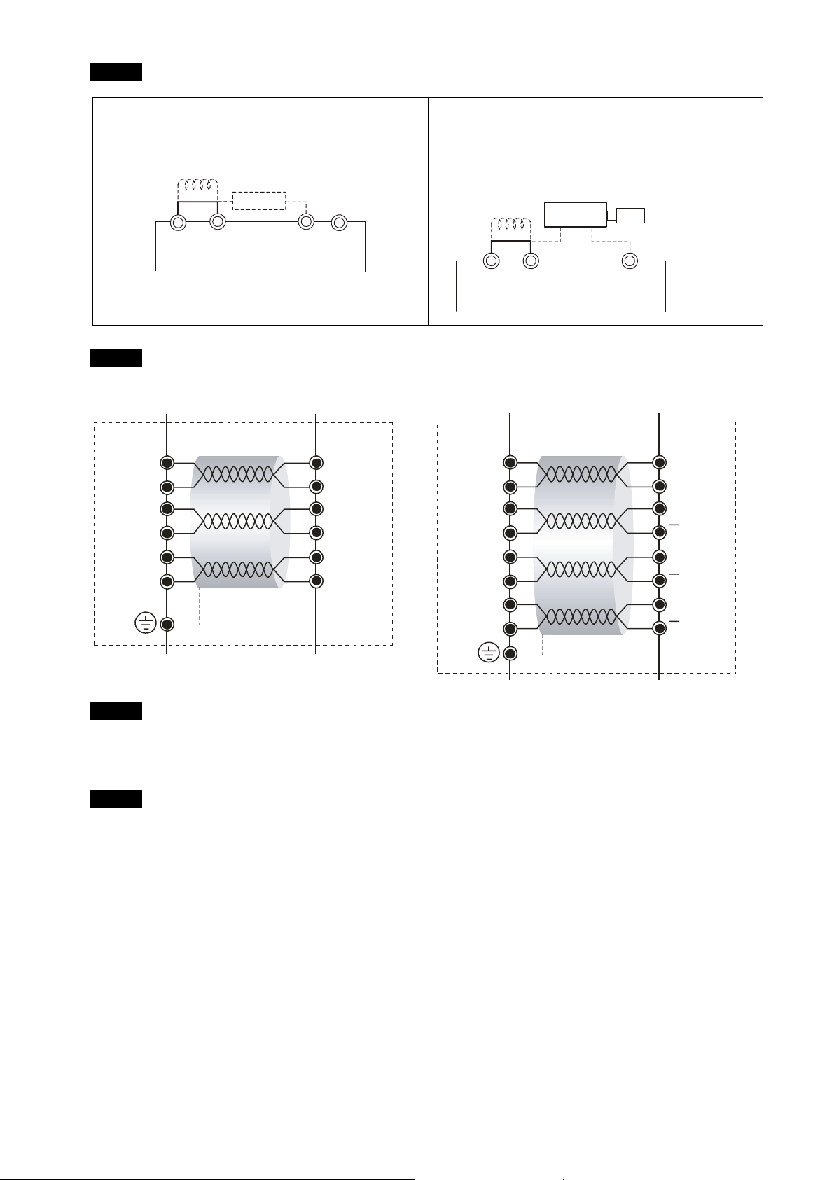
It may be a ground interference problem. If the motor or the three-phase power
supply is grounded, disconnect the ground wire. If the motor or three-phase power
supply has no ground wire, you can install a ground wire for anti-interference
protection.
It may be a grounding problem of the shield mesh (as the red thick line shown below).
If the shield mesh is properly grounded, the ground w ire can be removed; i f the shield
mesh has no grounding wire, install a ground wire for anti-interference protection.
3-14
Page 49

3. Machine Adjustment Procedure
PG Card
14,16
13,15
5
4
7
9
+24V
ACM
PO
Resol v e r
R1
R2
S2
S4
S1
S3
+V
-V
Output
Pressure sensor
4. If there is any abnormal condition that can not be solved, please contact the manufacturer.
Step 8. Adjustment of system transient response
Reduce the pressure rise time, increase Kp1 (Parameter 00-20) and reduce the Ki1 time
(Parameter 00-21)
For pressure overshoot, increase the Kp3 time (Parameter 00-24) and reduce the Ki3 time
(Parameter 00-25)
3-15
Page 50

Confluence Machine Tuning Procedure
Wiring according to Chapter 2
Carry out the automatic measurement of the motor’s parameters according to Step 1 and Step 2
described above for the Master and Slave, respectively. Then perform the following procedure
Master setting
Set the Parameter 03-06 = 1
Multifunction Output 2 (MO1)
Setting value
of Parameter
1: Operation indication
03-06
Connect the Master’s MO1 output terminal to the Slave’s SON terminal and Master's MCM
terminal to the Salve's COM terminal.
For the firmware version 2.03 and above, it is not necessary to perform the two steps
described above
Set the Parameter 03-13 = 1
Confluence Master/Slave Selection
Setting value
of Parameter
03-13
0: No function
1: Master 1
2: Slave/Master 2
3: Slave/Master 3
Set the Parameter 03-14
Slave's proportion of the Master’s flow
Setting value
of Parameter
0.0~6553.5%
03-14
For firmware version 2.03 and above, the Parameter 03-17 can be configured to determine the
activation level for the Slave
Slave’s activation level
Setting value
of Parameter
0~100%
03-17
3-16
Page 51

Slave setting
Parameter 01-01=1
Source of operation command
3. Machine Adjustment Procedure
Setting value
of Parameter
01-01
0: Operation by using the digital keypad
1: Operation by using the external terminals. The Stop button on the
keypad is disabled.
2: Communication using RS-485. The Stop button on the keypad is
disabled
For firmware version 2.03 and above, set the Parameter 01-01=2
Source of operation command
Setting value
of Parameter
01-01
0: Operation by using the digital keypad
1: Operation by using the external terminals. The Stop button on the
keypad is disabled.
2: Communication using RS-485. The Stop button on the keypad is
disabled
Set the Parameter 03-15 = 1
Source of Frequency Command
Setting value
of Parameter
0: Digital Operation Panel
1: RS485 Communication
03-15
Shut down the power and then supply the power again
2~5: reserved
Set an arbitrary value of the frequency command at the Master to check if the Slave has the
same value of the frequency command
Set 10rpm at the Master and then press RUN to see if the Slave is also running. If not, check
the wiring or the parameter setting for any problem
Set the Slave Parameter 03-13 = 2
Confluence Master/Slave Selection
Setting value
of Parameter
03-13
0: No function
1: Master 1
2: Slave/Master 2
3: Slave/Master 3
For firmware version 2.03 and above, the Parameter 03-21 can be set at the Slave to decide if
the Salve is performing the reversed operation for depressurization.
Note: If it is required to reverse the operation for depressurization at the Slave, it is necessary
to make sure that the pump outlet port is not installed with a check valve and the Parameter
03-16 should be set as 500%
3-17
Page 52

Slave reverse operation for depressurization
Setting value
of Parameter
03-21
Limit for the Slave reverse depressurization torque
Setting value
of Parameter
03-16
Shut off the power and the re-supply power for the Slave, and then set the Slave in the speed
control mode
Speed Control Mode
Setting value
of Parameter
00-09
In this case, the Master can be tuned according to the Step 3 – Step 8 described above
0: Disable
1: Enable
0~500%
0: Speed control
1: Pressure control
Confluence/Diversion Mode Adjustment
Procedure
Wiring according to Chapter 2
In a diversion condition, adjust various parameters of the Hybrid servo drive according to the Step
1 – Step 8 describe above
In a confluence condition, please refer to the machine adjustment procedure for the confluence
operation
Complete the above steps
Set the Master for pressure control mode
Parameter 00-09 = 1 for pressure control mode
Pressure control mode
Setting value
of Parameter
00-09
Set the Slave for speed control mode
0: Speed control
1: Pressure control
Parameter 00-09 = 0 for speed control mode
Speed Control Mode
Setting value
of Parameter
00-09
0: Speed control
1: Pressure control
3-18
Page 53

3. Machine Adjustment Procedure
Respectively set the master/slave multi-function input state. For the firmware version 2.03 and
above, it is necessary to set these parameters for the Slave only
Parameter 03-00~03-02 = 45 confluence/diversion signal input
Multi-function Input
Setting values
0: No function
of Parameters
45: Confluence/Diversion signal input
03-00~03-02
Through the controller, perform the entire confluence/diversion operation.
3-19
Page 54

4. Description of Parameters
4-1 Summary of Parameters
4-2 Detailed Description of Parameters
4. Description of Parameters
4-1
Page 55

4-1 Summary of Parameters
00 System Parameters a the parameter can be set during oper
ation
Parameter
code
00-00
00-01
00-02 Reset parameter settings
00-03 Software version Read only Read only ○ ○ ○
Function of the parameter Settings
12:230V, 7.5HP
13:460 V, 7.5HP
14:230V, 10HP
15:460V, 10HP
16:230V, 15HP
17:460V, 15HP
18:230V, 20HP
19:460V, 20HP
Hybrid servo drive model
code ID
Display of rated current of
the Hybrid servo drive
20:230V, 25HP
21:460V, 25HP
22:230V, 30HP
23:460V, 30HP
24:230V, 40HP
25:460V, 40HP
26:230V, 50HP
27:460V, 50HP
29:460V, 60HP
31:460V, 75HP
33:460V, 100HP
Display the model specific values Read only ○ ○ ○
5: Rest the kWh at drive stop
10: Reset parameter values
Default
value
Read only ○ ○ ○
0 ○ ○ ○
VF
FOCPG
FOCPM
4-2
Page 56

4. Description of Parameters
Parameter
a
a
code
00-04
00-05
Function of the parameter Settings
0: Display the output current (A)
1: Reserved
2: Display the actual output frequency (H)
3: Display the DC-BUS voltage (U)
4: Display the output voltage (E)
5: Display the output power angle (n)
6: Display the output power in kW (P)
7: Display the actual motor speed rpm (r)
8: Display the estimated output torque (%)
9: Display the PG feedback (G)
10: Reserved
11: Display the signal value of the analog input
terminal PO % (1.)
12: Display the signal value of the analog input
terminal PI % (2.)
Selection of multi-function
display
Analog output function
selection
13: Display the signal value of the analog input
terminal AUI % (3.)
14: Display temperature of the heat sink in °C (t.)
15: Display temperature of IGBT in °C (T)
16: The status of digital input (ON/OFF) (i)
17: The status of digital output (ON/OFF) (o)
18: Reserved
19: The corresponding CPU pin status of the digital
input (i.)
20: The corresponding CPU pin status of the digital
output (o.)
21~24: Reserved
25: Display the signal value of the analog input
terminal QI % (5.)
26: Display the actual pressure value (Bar) (b.)
27: Display the kWh value (K)
28: Display the motor temperature (currently only
support KTY84) (T.)
0: Output frequency (Hz) 0 ○ ○ ○
Default
value
0 ○ ○ ○
VF
FOCPG
FOCPM
a
a
1: Frequency command (Hz) ○ ○ ○
2: Motor speed (Hz) ○ ○ ○
3: Output current (A) ○ ○
00-06
00-07
00-08
Display the speed (rpm)
defined by the user
Maximum value for the
pressure command
Maximum pressure
feedback value
4: Output voltage
5: DC Bus voltage
6: Power factor
7: Power
8: Output torque
9: PO
10: PI
11: AUI
12~20: Reserved
0~39999 rpm 0 ○ ○ ○
0~250 Bar 250 ○ ○ ○
0~400 Bar 250 ○ ○ ○
○ ○ ○
○ ○ ○
○ ○ ○
○ ○ ○
○ ○ ○
4-3
Page 57

Parameter
code
00-09 Pressure control mode
00-10 Speed bandwidth 0~40Hz 20 ○ ○
a
00-11
a
00-12
a
00-13
a
00-14
a
00-15
a
00-16
Function of the parameter Settings
0: Speed control
1: Pressure control
Pressure feedback filtering
0.000~1.000 second 0.000 ○ ○ ○
time PO
Pressure command filtering
0.000~1.000 second 0.000 ○ ○ ○
time PI
Flow command filtering time
0.000~1.000 second 0.000 ○ ○ ○
QI
Percentage for the pressure
0.0~100.0% 100.0 ○ ○ ○
command value (Max)
Percentage for the pressure
0.0~100.0% 50.0 ○ ○ ○
command value (Mid)
Percentage for the pressure
0.0~100.0% 0.0 ○ ○ ○
command value (Min)
Default
value
0 ○ ○ ○
VF
FOCPG
FOCPM
a
00-17
a
00-18
a
00-19
a
00-20 P gain 1 0.0~1000.0 50.0 ○ ○ ○
a
00-21 I integration time 1 0.00~500.00 seconds 2.00 ○ ○ ○
a
00-22 P gain 2 0.0~1000.0 50.0 ○ ○ ○
a
00-23 I integration time 2 0.00~500.00 seconds 2.00 ○ ○ ○
a
00-24 P gain 3 0.0~1000.0 50.0 ○ ○ ○
a
00-25 I integration time 3 0.00~500.00 seconds 2.00 ○ ○ ○
a
00-26 Pressure stable region 0~100% 25 ○ ○ ○
a
00-27 Base pressure 0.0~100.0% 1.0 ○ ○ ○
a
00-28 Depressurization speed 0~100% 25 ○ ○ ○
a
00-29
Percentage for the flow
0.0~100.0% 100.0 ○ ○ ○
command value (Max)
Percentage for the flow
0.0~100.0% 50.0 ○ ○ ○
command value (Mid)
Percentage for the flow
0.0~100.0% 0.0 ○ ○ ○
command value (Min)
Ramp up rate of pressure
0~1000ms 0 ○ ○ ○
command
a
a
a
00-30
00-31
00-32
Ramp down rate of pressure
command
Ramp up rate of flow
command
Ramp down rate of flow
command
0~1000ms 100 ○ ○ ○
0~1000 ms 80 ○ ○ ○
0~1000 ms 80 ○ ○ ○
4-4
Page 58

4. Description of Parameters
Parameter
code
a
00-33 Valve opening delay time
00-34 Reserved
a
00-35
a
00-36
a
00-37 Differential gain
00-38
Function of the parameter Settings
Over-pressure detection
level
Detection of disconnection
of pressure feedback
Pressure/flow control
function selection
Default
value
0~200 ms
0~250 Bar 230 ○ ○ ○
0 : No function
1: Enable (only for the pressure feedback output signal
0
0 ○ ○ ○
VF
FOCPG
○ ○ ○
within 1~5V)
0.0~100.0 % 0.0 ○ ○ ○
Bit 0: 0: Switch the PI Gain according to the pressure
feedback level
1: Switch the PI Gain according to the
multi-function input terminal
Bit 1: 0: No pressure/flow control switch
1: Switch between the pressure and flow control
0 ○ ○ ○
FOCPM
4-5
Page 59

01 Motor Parameters a the parameter can be set during
operation
Parameter
code
01-00 Control mode
a
01-01
01-02
01-03 Motor’s rated frequency 0.00~600.00Hz
01-04 Motor’s rated voltage
Function of the parameter Settings
0: VF
1: Reserved
2: Reserved
3: FOCPG
4: Reserved
5: FOCPM
6: Reserved
0: Operation by using the digital keypad
1: Operation by using the external terminals. The Stop button
Source of operation
command
2: Communication using RS-485. The Stop button on the
Motor’s maximum operation
50.00~600.00Hz
frequency
230V Series: 0.1V~255.0V
460V Series: 0.1V~510.0V
on the keypad is disabled.
keypad is disabled
Default
value
5 ○ ○ ○
1 ○ ○ ○
60.00/
50.00
60.00/
50.00
220.0
440.0
○ ○ ○
○ ○ ○
○ ○
VF
FOCPG
FOCPM
a
01-05 Acceleration time setting 0.00~600.00 seconds 0.00 ○ ○ ○
a
01-06 Deceleration time setting 0.00~600.00 seconds 0.00 ○ ○ ○
01-07 Motor Parameter Auto Tuning 0: No function 0 ○ ○
a
a
2: Static test for induction motor(IM) ○ ○
3: Reserved ○ ○
5: Rolling test for PM motor ○
Rated current of the induction
01-08
motor (A)
Rated power of the induction
01-09
motor
Rated speed of the induction
01-10
motor
1: Rolling test for induction motor(IM) (Rs, Rr, Lm, Lx, no-load
○ ○
current)
4: Auto measure the angle between magnetic pole and PG
○
origin
40~120% of the drive’s rated current #.## ○
0~655.35kW #.## ○
0~65535rpm
1710 ○
1710 (60Hz 4-pole); 1410 (50Hz 4-pole)
01-11
Number of poles of the
2~20 4 ○
induction motor
4-6
Page 60

4. Description of Parameters
Parameter
code
01-12
01-13
01-14
01-15
01-16
01-17
01-18
Function of the parameter Settings
No-load current of the
0~Default value of Parameter 01-08 #.## ○
induction motor (A)
Stator resistance (Rs) of the
0~65.535Ω
induction Motor
Rotor resistance (Rr) of the
0~65.535Ω
induction Motor
Magnetizing inductance (Lm)
0.0~6553.5mH #.# ○
of the induction Motor
Total leakage inductance (Lx)
0.0~6553.5mH #.# ○
of the induction motor
Rated current of the
0~655.35 Amps 0.00 ○
synchronous motor
Rated power of the
0.00 – 655.35kW 0.00 ○
synchronous motor
Default
value
#.### ○
#.### ○
VF
FOCPG
FOCPM
01-19
01-20
01-21
01-22
01-23
01-24
01-25
Rated speed of the
synchronous motor
Number of poles of the
synchronous motor
Inertia of the synchronous
motor’s rotor
Stator’s phase resistance
(Rs) of the synchronous
motor
Stator’s phase inductance
(Ld) of the synchronous
motor
Stator’s phase inductance
(Lq) of the synchronous
motor
Back EMF of the
synchronous motor
0~65535rpm 0 ○
2~20 6 ○
0.0~6553.5 *10-4 kg.m
0.000~65.535Ω
0.00.0~655.35mH 0.00 ○
0.00.0~655.35mH 0.00 ○
0~65535 V/krpm 0 ○
2
0.0 ○
0.000 ○
01-26 Encode type
01-27
PG Offset angle of
synchronous motor
0: ABZ
1: ABZ+HALL (only used for Delta’s servo motors)
3 ○
2: ABZ+HALL
3: Resolver
0.0~360.0° 0.0 ○
4-7
Page 61

Parameter
code
01-28
01-29 Encoder pulse 1~20000 1024 ○ ○
01-30 Encoder’s input type setting
Function of the parameter Settings
Number of poles of the
1~5 1 ○
resolver
0: No function
1: Phase A leads in a forward run command and phase B
leads in a reverse run command
2: Phase B leads in a forward run command and phase A
leads in a reverse run command
3: Phase A is a pulse input and phase B is a direction input.
(low input=reverse direction, high input=forward direction)
4: Phase A is a pulse input and phase B is a direction input.
(low input=forward direction, high input=reverse direction)
5: Single-phase input
0: No function
Default
value
1 ○ ○
VF
FOCPG
FOCPM
01-31 System control
a
01-32
01-33 Carrier frequency 5KHz; 10KHz 5 ○ ○ ○
a
01-34 Reserved
01-35 Motor ID
Unity value of the system
inertia
1: ASR automatic tuning
2: Estimation of inertia
1~65535 (256 = 1 per unit) 400 ○ ○
0 : No function
16: Delta’s Hybrid servo motor ECMA-ER181BP3
(11kW220V)
17: Delta’s Hybrid servo motor ECMA-KR181BP3
(11kW380V)
18: Delta’s Hybrid servo motor ECMA-ER221FPS
(15kW220V)
19: Delta’s Hybrid servo motor ECMA-KR221FPS
(15kW380V)
21: Delta’s Hybrid servo motor ECMA-KR222APS
(20kW380V)
1 ○ ○
0 ○ ○ ○
01-36 Change the rotation direction
0: When the driver runs forward, the motor rotates
counterclockwise. When the driver runs reverse, the motor
rotates clockwise.
0 ○ ○ ○
1: When the driver runs forward, the motor rotates clockwise.
When the driver runs reverse, the motor rotates
counterclockwise..
4-8
Page 62

4. Description of Parameters
0-2 Parameters for Protection a the parameter can be set during
operation
Parameter
code
a
02-00 Software brake level
02-01 Present fault record 0: No error record 0 ○ ○ ○
02-02
02-03
02-04
02-05
02-06
Function of the parameter Settings
230V series: 350.0~450.0Vdc
460V series: 700.0~900.0Vdc
Second most recent fault
1: Over-current during acceleration (ocA) 0 ○ ○ ○
record
Third most recent fault
2: Over-current during deceleration (ocd) 0 ○ ○ ○
record
Fourth most recent fault
3: Over-current during constant speed (ocn) 0 ○ ○ ○
record
Fifth most recent fault
4: Ground fault (GFF) 0 ○ ○ ○
record
Sixth most recent fault
5: IGBT short-circuit (occ) 0 ○ ○ ○
record
6: Over-current at stop (ocS) ○ ○ ○
Default
value
380.0
760.0
VF
FOCPG
○ ○ ○
FOCPM
7: Over-voltage during acceleration (ovA) ○ ○ ○
8: Over-voltage during deceleration (ovd) ○ ○ ○
9: Over-voltage during constant speed (ovn) ○ ○ ○
10: Over-voltage at stop (ovS) ○ ○ ○
11: Low-voltage during acceleration (LvA) ○ ○ ○
12: Low-voltage during deceleration (Lvd) ○ ○ ○
13: Low-voltage during constant speed (Lvn) ○ ○ ○
14: Low-voltage at stop (LvS) ○ ○ ○
15: Phase loss protection (PHL) ○ ○ ○
16: IGBT over-heat (oH1) ○ ○ ○
17: Heat sink over-heat for 40HP and above (oH2) ○ ○ ○
20: Fan error signal output (Fan) ○ ○ ○
18: TH1 open: IGBT over-heat protection circuit error
○ ○ ○
(tH1o)
19: TH2 open: heat sink over-heat protection circuit error
○ ○ ○
(tH2o)
21: Hybrid servo drive overload (oL) ○ ○ ○
22: Motor over-load (EoL1) ○ ○ ○
23: Reserved
24: Motor over-heat, detect by PTC (oH3) ○ ○ ○
25: Reserved
26: Over-torque 1 (ot1) ○ ○ ○
4-9
Page 63

Parameter
code
Function of the parameter Settings
27: Over-torque 2 (ot2)
28: Reserved
29: Reserved
30: Memory write error (cF1)
31: Memory read error (cF2)
32: Isum current detection error (cd0)
33: U-phase current detection error (cd1)
34: V-phase current detection error (cd2)
35: W-phase current detection error (cd3)
36: Clamp current detection error (Hd0)
37: Over-current detection error (Hd1)
38: Over-voltage detection error (Hd2)
39: Ground current detection error (Hd3)
40: Auto tuning error (AuE)
41: Reserved
42: PG feedback error (PGF1)
43: PG feedback loss (PGF2)
44: PG feedback stall (PGF3)
45: PG slip error (PGF4)
46: Reserved
47: Reserved
48: Reserved
49: External fault input (EF)
50: Emergency stop (EF1)
51: Reserved
52: Password error(PcodE)
53: Reserved
54: Communication error (cE1)
55: Communication error (cE2)
56: Communication error (cE3)
57: Communication error (cE4)
58:Communication time out (cE10)
59: PU time out (cP10)
60: Braking transistor error (bF)
61~63: Reserved
64: Safety relay Error (SRY)
65: PG card information error (PGF5)
66: Over pressure (ovP)
Default
value
VF
FOCPG
FOCPM
○ ○ ○
○ ○ ○
○ ○ ○
○ ○ ○
○ ○ ○
○ ○ ○
○ ○ ○
○ ○ ○
○ ○ ○
○ ○ ○
○ ○ ○
○ ○ ○
○ ○ ○
○ ○
○ ○ ○
○ ○
○ ○
○ ○
○ ○
○ ○ ○
○ ○ ○
○ ○ ○
○ ○ ○
○ ○ ○
○ ○ ○
○ ○ ○
○ ○ ○
○ ○ ○
○ ○ ○
○ ○ ○
○ ○ ○
○ ○ ○
○ ○ ○
○ ○ ○
○
○ ○ ○
4-10
Page 64

4. Description of Parameters
Parameter
code
a
02-07 Low voltage level
a
02-08 PTC action selection
a
02-09 PTC level
a
02-10 PTC detection filtering time 0.00~10.00 seconds 0.20 ○ ○ ○
a
02-11 PTC type
a
02-12 Motor fan activation level
a
02-13
Function of the parameter Settings
67: Pressure feedback fault (PfbF)
160.0~220.0Vdc
320.0.0~440.0Vdc
0: Warn and keep operation
1: Warn and ramp to stop
2: Warn and coast to stop
0.0~150.0%
0.0~150.0℃
0: Not assigned
1: KTY84
0.0~100.0%
0.0~150.0℃
0: Inverter motor
Electronic thermal relay
1: Standard motor
selection 1
2: Disable
Default
value
180.0
360.0
0 ○ ○ ○
50.0 ○ ○ ○
0 ○ ○ ○
50.0 ○ ○ ○
2 ○ ○ ○
VF
FOCPG
○ ○ ○
○ ○ ○
FOCPM
a
02-14
02-15
02-16
02-17 DC voltage at malfunction 0.0~6553.5 V Read only ○ ○ ○
02-18
02-19
Electronic thermal
30.0~600.0 seconds 60.0 ○ ○ ○
characteristic for motor
Output frequency at
0.00~655.35 Hz Read only ○ ○ ○
malfunction
Output voltage at
0.0~6553.5 V Read only ○ ○ ○
malfunction
Output current at
0~655.35 Amps Read only ○ ○ ○
malfunction
IGBT temperature at
0.0~6553.5 ℃ Read only ○ ○ ○
malfunction
4-11
Page 65

03 Digital/Analog Input/Output Parameters a the parameter can be set during
operation
Parameter
code
03-00
03-01
03-02
a
03-03 Digital input response time 0.001~ 30.000 sec 0.005 ○ ○ ○
a
03-04
a
03-05
a
03-06
a
03-07
Function of the parameter Settings
Multi-function input
command 3 (MI3)
Multi-function input
command 4 (MI4)
Multi-function input
command 5 (MI5)
Digital input operation
direction
Multi-function output 1
(Relay 1)
Multi-function Output 2
(MO1)
Multi-function Output 3
(MO2)
0: No function
44: Injection signal input
45: Confluence/Diversion signal input
46: Reserved
47: Multi-level pressure PI command 1
48: Multi-level pressure PI command 2
0~65535
0: No function
1: Operation indication
9: Hybrid servo drive is ready
11: Error indication
44: Displacement switch signal
45: Motor fan control signal
Default
value
0 ○ ○ ○
0 ○ ○ ○
0 ○ ○ ○
0 ○ ○
11 ○ ○ ○
0 ○ ○ ○
0 ○ ○ ○
VF
FOCPG
FOCPM
a
03-08
a
03-09
03-10
03-11
a
03-12 Reserved
03-13
03-14
a
03-15
Multi-function output
direction
Low-pass filter time of
keypad display
Maximum output voltage for
pressure feedback
Minimum output voltage for
pressure feedback
Confluence Master/Slave
Selection
Slave's proportion of the
Master’s flow
Source of frequency
command
0~65535
0.001~65.535 seconds 0.010 ○ ○ ○
5.0~10.0 V 10.0 ○ ○ ○
0.0~10.0 V 0.0 ○ ○ ○
0: No function
1: Master 1
2: Slave/Master 2
3: Slave/Master 3
0.0~65535.5 % 100.0 ○ ○ ○
0: Digital keypad
1: RS485 Communication
2~5: Reserved
0 ○
0 ○ ○ ○
0 ○ ○ ○
a
03-16
a
03-17 Slave’s activation level 0.0~100.0% 50.0 ○ ○ ○
Limit for the Slave reverse
0~500% 20 ○ ○ ○
depressurization torque
4-12
Page 66

4. Description of Parameters
Parameter
code
a
03-18
a
03-19 Time-out detection 0.0~100.0 seconds 0.0 ○ ○ ○
a
03-20 Start-up display selection
a
03-21
Function of the parameter Settings
0: Warn and keep operation
Communication error
treatment
Slave reverse operation for
depressurization
1: Warn and ramp to stop
2: Warn and coast to stop
3: No action and no display
0: F (frequency command)
1: H (actual frequency)
2: Multi-function display (user-defined 00-04)
3: A (Output current)
0: Disabled
1: Enabled
Default
value
3 ○ ○ ○
0 ○ ○ ○
0 ○ ○ ○
VF
FOCPG
FOCPM
4-13
Page 67

4-2 Detailed Description of Parameters
00 System Parameters a the parameter can be set during opera
tion
Control mode VF FOCPG FOCPM
Hybrid servo drive model code ID
Factory default: Read only
Control mode VF FOCPG FOCPM
Settings Read only
Display of rated current of the Hybrid servo drive
Factory default: Read only
Settings Read only
Parameter 00-00 is used to determine the capacity of the Hybrid servo motor which has been
configured in this parameter in factory. In addition, the current value of Parameter (00-01) can be
read out to check if it is the rated current of the corresponding model.
Display value of the current
value of Parameter 00-01 for the related Parameter 00-00.
230V Series
Power (KW)
Horse Power (HP)
Model ID
5.5 7.5 11 15 18.5 22 30 37
7.5 10 15 20 25 30 40 50
12 14 16 18 20 22 24 26
460V Series
Power (KW)
Horse Power (HP)
5.5 7.5 11 15 18.5 22 30 37 45 55 75
7.5 10 15 20 25 30 40 50 60 75 100
Model ID
13 15 17 19 21 23 25 27 29 31 33
Control mode VF FOCPG FOCPM
Reset parameter settings
Settings 0: No function
5: Rest the kWh at drive stop
10: Reset parameter values
Factory default: 0
If it is necessary to restore the parameters to factory default, just set this parameter to “10”.
Control mode VF FOCPG FOCPM
Software version
Settings
Read only
Factory default: #.##
a
Control mode VF FOCPG FOCPM
Selection of multi-function display
Factory default: 0
Settings 0: Display the output current (A)
1: Reserved
2: Display the actual output frequency (H)
U
U
4-14
Page 68

4. Description of Parameters
3: Display the DC-BUS voltage (U)
4: Display the output voltage (E)
5: Display the output power angle (n)
6: Display the output power in kW (P)
U
U
U
U
7: Display the actual motor speed(r 00: forward speed; - 00:
U
negative speed)
U
8: Display the estimated output torque (%) (t 0.0: positive
torque; - 0.0: negative torque) (%)
9: Display the PG feedback (G)
10: Reserved
11: Display the signal value of the analog input terminal PO
with 0~10V mapped to 0~100%
12: Display the signal value of the analog input terminal PI
with 0~10V mapped to 0~100%
13: Display the signal value of the analog input terminal PI
with -10~10V mapped to 0~100%
14: Display temperature of the heat sink in °C (t.)
15: Display temperature of the IGBT power module °C
16: The status of digital input (ON/OFF)
17: The status of digital output (ON/OFF)
18: Reserved
19: The corresponding CPU pin status of the digital input
20: The corresponding CPU pin status of the digital output
21~24: Reserved
25: Display the signal value of the analog input terminal OI
with 0~10V mapped to 0~100%
26: Display the actual pressure value (Bar)
27: Display the kWh value
28: Display the motor temperature (currently only support
KTY84)
U
U
U
U
U
U
U
U
U
U
U
U
U
U
U
U
U
This parameter defines the contents to be displayed in the U page of the digital keypad
KPV-CE01 (as shown in the figure).
a
Control mode VF FOCPG FOCPM
Analog output function selection
Settings 0~20
Summary of functions
Setting
Function Description
Val ue
0 Output frequency (Hz) The maximum frequency is 100%
1 Frequency command (Hz) The maximum frequency is 100%
2 Motor speed (Hz) 600Hz is used as 100%
4-15
Factory default: 0
Page 69

3 Output current (A) 2.5 times of the rated current of the Hybrid servo
4 Output voltage 2 times of the rated current of the Hybrid servo drive
5 DC BUS voltage 450V (900V) =100%
6 Power factor -1.000~1.000=100%
7 Power Rated power of the drive =100%
8 Output torque Rated torque =100%
9 PO (0~10V=0~100%)
10 PI (0~10V=0~100%)
11 AUI (-10~10V=0~100%)
12~20 Reserved
Control mode VF FOCPG FOCPM
Display the speed (rpm) defined by the user
drive is used as 100%
is used as 100%
Factory default: 0
Settings 0~39999 rpm
Set the maximum speed of the motor corresponding to the 100% flow.
a
Control mode VF FOCPG FOCPM
Maximum value for the pressure command
Factory default: 250
Settings 0~250Bar
The 0~10V for the pressure command on the controller is mapped to 0~the value of this
parameter.
a
Control mode VF FOCPG FOCPM
Maximum pressure feedback value
Settings 0~400Bar
Factory default: 250
The 0~10V for the pressure sensor is mapped to 0~the value of this parameter.
Control mode VF FOCPG FOCPM
Pressure control mode
Settings 0: Speed control
1: Pressure control
Factory default: 0
This parameter determines the control mode of the Hybrid servo drive. It is recommended to use
the speed control at the initial start up. After the motor, pump, pressure sensor, and the entire
system are checked without any error, switch to the pressure control mode to enter the process
control.
Control mode FOCPG FOCPM
Speed bandwidth
Settings 0~40Hz
Factory default: 20
Set the speed response. The larger value indicates the faster response.
a
Pressure feedback filtering time PO
4-16
Page 70

4. Description of Parameters
a
a
Control mode VF FOCPG FOCPM
Noises may reside in the analog input signals of the control terminals PO, PI, and QI. The noise
may affect the control stability. Use an input filter to eliminate such noise.
If the time constant is too large, a stable control is obtained with poorer control response. If it is too
small, a fast response is obtained with unstable control. If the optimal setting is not known, adjust it
properly according to the instability or response delay.
a
a
a
Control mode VF FOCPG FOCPM
To set these parameters, it is necessary to set Parameter 00-09 as 1
Parameter 00-04 = 12 for PI input voltage
Pressure feedback filtering time PI
Pressure feedback filtering time QI
Factory default: 0.000
Settings 0.000~1.000 seconds
Percentage for the pressure command value (Max)
Percentage for the pressure command value (Mid)
Percentage for the pressure command value (Min)
Factory default: 100.0
Settings 0.0~100.0%
Send the maximum pressure command through the controller and then check the multi-function
display page to enter this value into 00-14
Send a half pressure command through the controller and then check the multi-function display
page to enter this value into 00-15
Send the minimum pressure command through the controller and then check the multi-function
display page to enter this value into 00-16
Example: If the pressure sensor indicates 250bar at 10V. If the controller’s maximum pressure of
140bar corresponds to 10V, then Parameter 00-07=140. Set the pressure as 140bar by using
the controller, the voltage value shown on the display is about 56.0 (140/250 * 100%). Enter
this value into the Parameter 00-14. Then set the pressure as 70bar on the controller, and
now the value displayed on the keypad is about 28.0 (70/250 * 100%). Enter this value to the
Parameter 00-15. Then set the pressure as 0 bar on controller, and the voltage value shown
on the keypad is about 0.0 (0/250 * 100%). Enter this value in the Parameter 00-16.
a
a
a
Control mode VF FOCPG FOCPM
Percentage for the flow command value (Max)
Percentage for the flow command value (Mid)
Percentage for the flow command value (Min)
Factory default: 100.0
To set these parameters, it is necessary to set Parameter 00-09 as 1
Parameter 00-04 = 25 for QI input voltage
Send the 100% flow rate through the controller and then check the multi-function display page to
enter this value into 00-17
Send the 50% flow rate through the controller and then check the multi-function display page to
enter this value into 00-18
Settings 0.0~100.0%
4-17
Page 71

d
Send the 0% flow rate through the controller and then check the multi-function display page to
enter this value into 00-19
a
a
a
Control mode VF FOCPG FOCPM
a
a
a
Control mode VF FOCPG FOCPM
a
Control mode VF FOCPG FOCPM
P gain 1
P gain 2
P gain 3
Settings 0.0~1000.0
I integration time 1
I integration time 2
I integration time 3
Settings 0.00 – 500.00 seconds
Differential gain
Settings 0.0~100.0 %
a
Control mode VF FOCPG FOCPM
Pressure stable region
Settings 0~100%
Factory default: 50.0
Factory default: 2.00
Factory default: 0.0
Factory default: 25
Pressure
Pressure Feedback
00-26
00-26
P3, I3
P2, I2
Pressure
Comman
P2, I2
P1, I1
Time
Adjust the Kp value to a proper level first, and then adjust the Ki value (time). If the pressure has
overshoot, adjust the kd value.
Appropriate Kp value
Kp value is too low
4-18
Kp va lue i s t o o hi gh
Page 72

4. Description of Parameters
Appropriate Ki value (time)
Kd va lue i s t o o l o w
a
Control mode VF FOCPG FOCPM
Base pressure
Settings 0.0~100.0%
Ki value is too high (time)
Appropriate Kd value
Factory default: 1.0
Ki value is too low (time)
Kd va lue is too hi gh
Set the minimum pressure value 100% corresponding to Parameter 00-08
Typically, it is necessary to maintain a certain base pressure to ensure that the oil pipe is in fully
filled condition so as to avoid the activation delay of the cylinder when a pressure/flow command is
activated.
a
Control mode VF FOCPG FOCPM
Depressurization speed
Settings 0~100%
Factory default: 25
Set the highest rotation speed at depressurization. The 100% value is mapped to Parameter 01-02
(the maximum rotation speed of the motor)
a
a
Control mode VF FOCPG FOCPM
Ramp up rate of pressure command
Ramp down rate of pressure command
Factory default: 100
Settings 0~1000ms
Ramp the pressure value for the pressure command so as to reduce the vibration of the machine.
Set the time required for ramping the pressure from 0~the maximum pressure (00-08).
Pressure
command given
to controller
Pressure
command after
driver processing
Time
a
a
00-29 00-30
Ramp up rate of flow command
Ramp down rate of flow command
4-19
Page 73

2
Control mode VF FOCPG FOCPM
Factory default: 80
Settings 0~1000ms
Ramp the flow value for the flow command so as to reduce the vibration of the machine.
Set the time required for ramping the flow from 0~the maximum flow (01-02).
Flow command
given to
controller
Flow command
after driver
processing
00-31 00-3
a
Control mode VF FOCPG FOCPM
Valve opening delay time
Settings 0 – 200ms
Factory default: 0
Time
When both the pressure command and flow command activate the machine to start from idle, the
flow starts to output. However, due to the slower response of the valve in the
hydraulic circuit, the
sudden surge of the pressure may occur. The pressure may recover to normal till the valve is fully
opened.
To avoid the aforementioned effect, set this parameter to increase time for the flow output
delay.
Pressure
Command
Parameter 00-33
Flow
Command
Reserved
a
Control mode VF FOCPG FOCPM
Over-pressure detection level
Settings 0~250 Bar
Before pressure
feedback adjustment
After pressure
feedback adjustment
Before flow feedback
adjustment
After flow feedback
adjustment
Factory default: 230
When the pressure feedback exceeds this parameter setting, an “ovP over pressure” error
message may occur.
a
Control mode VF FOCPG FOCPM
Detection of disconnection of pressure feedback
Factory default: 0
Settings 0: No function
4-20
Page 74

4. Description of Parameters
1: Enable (only for the pressure feedback output signal within 1~5V)
When this parameter is set as 1 and if the pressure feedback signal is below 1V, an "Pfbf pressure
feedback fault” error message may occur.
a
Control mode VF FOCPG FOCPM
Pressure/flow control function selection
Factory default: 0
Bit 0:
Settings
0: Switch the PI Gain according to the pressure feedback level
1: Switch the PI Gain according to the multi-function input terminal
Bit 1:
0: No pressure/flow control switch
1: Switch between the pressure and flow control
When the Bit 0 of this parameter is set as 1, the PI Gain for the pressure can be switched in
conjunction with the multi-function input terminal
Multi-function input
terminal = 47
Multi-function input
terminal = 48
OFF OFF PI1(Parameters 00-20 & 00-21)
ON OFF PI2(Parameters 00-22 & 00-23)
OFF ON PI3(Parameters 00-24 & 00-25)
When the Bit 1 of this parameter is set as 1, the pressure feedback is lower than the pressure
stable region (please refer to the description of Parameter 00-26) so the flow control will be
performed.
When it enters the pressure stable region, the pressure control will be performed.
4-21
Page 75

01 Motor Parameters a the parameter can be set during
operation
Control mode VF FOCPG FOCPM
This parameter determines the control mode of this AC motor.
0: V/F control, the user can design the required V/F ratio. It is used for induction motors.
1~2: Reserved
3: FOC vector control + Encoder. It is used for induction motors.
4: Reserved
5: FOC vector control + Encoder. It is used for synchronous motors.
6: Reserved
Control mode
0:V/F
1: Reserved
2: Reserved
Settings
3: FOCPG
4: Reserved
5: FOCPM
6: Reserved
Factory default: 5
a
Control mode VF FOCPG FOCPM
Source of operation command
Factory default: 1
Settings 0: The operation command is controlled by the digital operation panel
1: The operation command is controlled by the external terminals. The
STOP button on the keypad panel is disabled
2: The operation command is controlled by the communication interface.
The STOP button on the keypad panel is disabled
For the operation command, press the PU button to allow the “PU” indicator to be lit. In this case,
the RUN, JOG, and STOP button are enabled.
Control mode VF FOCPG FOCPM
Motor’s maximum operation frequency
Factory default:
60.00/50.00
Settings 50.00 – 600.00Hz
Set the maximum operation frequency range of the motor. This setting is corresponding to the
maximum flow for the system.
Control mode VF FOCPG FOCPM
Motor’s rated frequency
Factory default:
60.00/50.00
Settings 0.00~600.00Hz
Typically, this setting is configured according to the rated voltage and frequency listed in the
specifications on the motor’s nameplate. If the motor is intended for 60Hz, set this value as 60Hz;
if the motor is intended for 50Hz, set this value as 50Hz.
Control mode VF FOCPG
Motor’s rated voltage
Settings 230V series: 0.1 – 255.0V
4-22
Factory default: 220.0/440.0
Page 76

4. Description of Parameters
460V series: 0.1 – 510.0V
Typically, this setting is configured according to the rated operation voltage shown on the motor’s
nameplate. If the motor is intended for 220V, set this value as 220.0V; if the motor is intended for
200V, set this value as 200.0V.
a
Control mode VF FOCPG FOCPM
a
Control mode VF FOCPG FOCPM
Acceleration time setting
Settings
Deceleration time setting
0.00 – 600.00 seconds
Settings 0.00 – 600.00 seconds
Factory default: 0.00
Factory default: 0.00
The acceleration time determines the time required for the Hybrid servo motor to accelerate from
0.0Hz to [the motor’s maximum frequency] (01-02). The deceleration time determines the time
required for the Hybrid servo motor to decelerate from [the motor’s maximum frequency] (01-02)
to 0.0Hz.
Motor Parameter Auto Tuning
Factory default: 0
Settings Control mode
0: No function
1: Rolling test for induction motor(IM) (Rs, Rr, Lm,
Lx, no-load current)
4: Auto measure the angle between magnetic pole
2: Static test for induction motor(IM)
3: Reserved
and PG origin
5: Rolling test for PM motor
VF FOCPG FOCPM
○ ○
○ ○
○ ○
○
○
If the parameter is set as 1~2, it will perform the parameter automatic tuning for the Induction
motor. In this case, press the [Run] button to perform the automatic measurement operation
immediately. After the measurement is complete, the values are filled into Parameters 01-13~16
(no-load current, Rs, Rr, Lm, and Lx), respectively.
Induction motor AUTO-Tuning procedure:( Rolling test)
1. All parameters of the Hybrid servo drive are set to factory settings and the motor is connected
correctly.
2. Users are strongly advised to disconnect the motor from any load before tuning. That is to say,
the motor contains only the output shaft and connects to neither a belt nor a decelerator.
Otherwise, it will be impossible to disconnect the motor from any loads. Static tuning is
advised . ※
3. Set the rated voltage 01-04, rated frequency 01-03, rated current 01-08, rated power 01-09,
rated speed 01-10, and number of poles 01-11 of the motor with correct values, respectively.
For the acceleration/deceleration time, please set the correct values.
4. Set Parameter 01-07 as 1 and then press the RUN button on the keypad. The auto tuning
process for the motor is carried out immediately. (Note: the motor starts running).
5. After the process is finished, check if the motor’s parameters (parameters 01-13 ~ 16) have
4-23
Page 77

been automatically entered with the measurement data.
6. Equivalent circuit of the motor
I
V
S
Motor equivalent circuit used by VJ
NOTE
* When the static tuning (parameters 01-07 = 2) is used, you must enter the no-load current ot the motor. It is generally
20 to 50% of the rated current.
Rs
Pr. 01-13
Lx
Pr .01-16
Lm
Pr.01-15
Rr
Pr. 01-14
If the parameter is set as 5, it will perform the parameter automatic tuning for the synchronous
motor. In this case, press the [Run] button to perform the automatic measurement operation
immediately. After the measurement is complete, the values are filled into Parameters 01-22 (Rs),
01-23 & 24 (Ld & Lq), 01-25 (Back EMF of the synchronous motor), respectively.
Synchronous motor AUTO-Tuning procedure:(static measurement)
1. All parameters of the Hybrid servo drive are set to factory settings and the motor is
connected correctly.
2. Set the rated current 01-17, rated power 01-18, rated speed 01-19, and number of poles
01-20 of the motor with correct values, respectively. For the acceleration/deceleration time,
please set the values according to the motor’s capacity.
3. Set Parameter 01-07 as 5 and then press the RUN button. The auto tuning process for the
motor is carried out immediately. (Note: the motor starts running slightly).
4. After the process is finished, check if the motor’s parameters (parameters 01-22 ~ 01-25)
have been automatically entered with the measurement data.
If the Parameter is set as 4, the automatic measurement of the angle between magnetic pole and
the PG origin for the synchronous motor is performed. In this case, press the [Run] button to
immediately perform automatic measurement. The measured data will be entered into Parameter
01 -27.
Angle between magnetic pole and the PG origin Auto-Tuning process for the synchronous motor:
1. After the measurement process for parameter value of 5 is performed completely or
manually enter the Parameters 01-03, 01-17 and 01-25, respectively.
2. Before tuning, it is recommended to separate the motor and the load.
3. Set Parameter 01-07 as 4 and then press the RUN button on the keypad. The auto tuning
process for the motor is carried out immediately. (Note: the motor starts running).
4. After the process is complete, please check if the values for the angle between magnetic
poles and PG origin have been automatically entered in the Parameter 01-27.
4-24
Page 78

4. Description of Parameters
Control mode FOCPG
Rated current of the induction motor (A)
Unit: Ampere
Factory default: #.##
Settings 40~120% of the rated driving current
To set this parameter, the user can set the rated motor current range shown on the motor’s
nameplate. The factory default is 90% of the rated current of the Hybrid servo drive.
For example: For the 7.5HP (5.5kW) motor, the rated current is 25, the factory settings: 22.5A.
The customers can set the parameter within the range 10 ~ 30A.
25*40%=10 25*120%=30
a
Control mode FOCPG
Rated power of the induction motor
Factory default: #.##
Settings 0 – 655.35kW
Set the motor’s rated power. The factory default value is the power of the Hybrid servo drive.
a
Control mode FOCPG
Rated speed of the induction motor
Factory default:
1710 (60Hz 4-pole)
1410 (50Hz 4-pole)
Settings 0~65535
This parameter sets the rated speed of the motor. It is necessary to refer to the specifications
shown on the motor’s nameplate.
Control mode FOCPG
Number of poles of the induction motor
Factory default: 4
Settings 2~20
This parameter sets the number of motor number of poles (odd number is not allowed).
Control mode FOCPG
No-load current of the induction motor (A)
Unit: Ampere
Factory default: 40
Settings 0~ Default value of Parameter 01-08
The factory default is 40% of the rated current of the Hybrid servo drive.
Control mode FOCPG
Stator resistance (Rs) of the induction motor
Factory default: #.##
Control mode FOCPG
Rotor resistance (Rr) of the induction motor
Settings 0~65.535Ω
Control mode FOCPG
Control mode FOCPG
Magnetizing inductance (Lm) of the induction motor
Total leakage inductance (Lx) of the induction motor
Factory default: #.##
Factory default: #.##
Factory default: #.##
4-25
Page 79

Settings 0.0~6553.5mH
Control mode FOCPM
Rated current of the synchronous motor
Settings 0~655.35 Amps
Factory default: 0.00
The user can set the rated current shown on the synchronous motor’s nameplate.
Control mode FOCPM
Rated power of the synchronous motor
Settings 0.00 – 655.35kW
Factory default: 0.00
This Parameter sets the rated power of the synchronous motor.
Control mode FOCPM
Rated speed of the synchronous motor
Settings 0~65535
Factory default: 0
This parameter sets the rated speed of the synchronous motor. It is necessary to refer to the
specifications shown on the motor’s nameplate.
Control mode FOCPM
Number of poles of the synchronous motor
Factory default: 6
Settings 2~20
This parameter sets the number of the synchronous motor’s number of poles (odd number is not
allowed).
Control mode FOCPM
Inertia of the synchronous motor’s rotor
Factory default: 0.0
Settings 0.0~6553.5 *10
-4
kg.m2
Control mode FOCPM
Stator’s phase resistance (Rs) oth the synchronous motor
Factory default: 0
Settings 0~65.535Ω
Enter the phase resistance of the synchronous motor.
Control mode FOCPM
stator’s phase inductance(Ld) of the synchronous motor
stator’s phase inductance(Lq) of the synchronous motor
Factory default: 0.00
Settings 0.0~655.35mH
Enter the synchronous motor’s phase inductance. For surface type magnets (SPM), Ld = Lq; for
built-in magnets (IPM), Ld ≠ Lq.
Control mode FOCPM
Back EMF of the synchronous motor
Settings 0~65535 V/krpm
Factory default: 0
Enter the back EMF of the synchronous motor.
4-26
Page 80

4. Description of Parameters
B
Control mode FOCPM
Encoder type selection
Settings 0: ABZ
1: ABZ+HALL (only used for Delta’s servo motors)
2: ABZ+HALL
3: Resolver
Look up table for Encoders & PG cards
Parameter Setting Encoder Type Applicable PG Card
01-26=0
01-26=1,2
01-26=3
A, B, Z EMVJ-PG01U
A, B, Z+U, V, W EMVJ-PG01U
Resolver EMVJ-PG01/02R
Control mode FOCPM
PG Offset angle of synchronous motor
Settings 0.0~360.0°
Offset angle of the PG origin for the synchronous motor.
Factory default: 3
Factory default: 0.0
Control mode FOCPM
Number of poles of the resolver
Settings 1~5
Factory default: 1
Control mode FOCPG FOCPM
Encoder Pulse
Settings 1~20000
Factory default: 1024
This parameter can be set the encoder's number of pulses per revolution (PPR).
Control mode FOCPG FOCPM
Encoder’s input type setting
Settings 0: No function
Factory default: 1
1: Phase A leads in a forward run command and phase B leads in a reverse
run command.
Forward
Rotation
Forward Rotation
A
B
Re ve rse Rota ti on
2: Phase B leads in a forward run command and phase A leads in a reverse
run command.
Forward Rotation
A
Forward
Rotation
4-27
Reverse Rotatio n
Page 81

B
3: Phase A is a pulse input and phase B is a direction input. (low
input=reverse direction, high input=forward direction).
Forward Rota tio n Reverse Rotation
A
Forward
Rotation
4: Phase A is a pulse input and phase B is a direction input. (low
input=forward direction, high input=reverse direction).
Forward
Rotation
Forward Rotation
A
B
Reverse Rotation
5: Single-phase input
Forward
Rotation
A
Enter the correct setting for the pulse type is helpful in controlling the stability.
Control mode FOCPG FOCPM
System control
Settings 0: No function
1: ASR automatic tuning
2: Estimation of inertia
Factory default: 1
If the setting value is 1: The speed control gain is determined by Parameters 00-10
If the setting value is 2: The system inertia is estimated. Please refer to descriptions in Chapter 3
a
Control mode FOCPG FOCPM
Unity value of the system inertia
Settings 1~65535 (256 = 1 per unit)
Factory default: 400
Control mode FOCPG FOCPM
Carrier frequency
Settings 5 kHz; 10kHz
Factory default: 5
When this parameter is configured, please re-start the Hybrid servo drive.
The carrier frequency of the PWM output has a significant influence on the electromagnetic noise
of the motor. The heat dissipation of the Hybrid servo drive and the interference from the
environment may also affect the noise. Therefore, if the ambient noise is greater than the motor
noise, reducing the carrier frequency of the drive may have the benefits of reducing a temperature
rise; if the carrier frequency is high, even if a quiet operation is obtained, the overall wiring and
interference control should be taken into consideration.
a
Reserved
Control mode FOCPG FOCPM
Motor ID
Factory default: 0
4-28
Page 82

4. Description of Parameters
Settings 0 : No function
16: Delta’s Hybrid servo motor ECMA-ER181BP3 (11kW220V)
17: Delta’s Hybrid servo motor ECMA-KR181BP3 (11kW380V)
18: Delta’s Hybrid servo motor ECMA-ER221FPS (15kW220V)
19: Delta’s Hybrid servo motor ECMA-KP221FPS (15kW380V)
21: Delta’s Hybrid servo motor ECMA-KR222APS (20kW380V)
Control mode FOCPG FOCPM
Change the rotation direction
Factory default: 0
Settings
0: When the driver runs forward, the motor rotates counterclockwise. When
the driver runs reverse, the motor rotates clockwise.
1: When the driver runs forward, the motor rotates clockwise. When the
driver runs reverse, the motor rotates counterclockwise.
This parameter can be modified only when the machine is shut down. For an induction motor after
the parameters are configured completely, it will change the running direction. For a synchronous
motor, it is necessary to perform the magnetic pole detection and re-start the drive.
4-29
Page 83

0-2 Parameters for Protection a the parameter can be set during
operation
a
Control mode VF FOCPG FOCPM
Software brake level
Factory default:
380.0/760.0
Settings 230V series: 350.0~450.0Vdc
460V series: 700.0~900.0Vdc
Sets the reference point of software brake. The reference value is the DC bus voltage.
Present fault record
Second most recent fault record
Third most recent fault record
Fourth most recent fault record
Fifth most recent fault record
Sixth most recent fault record
Settings Control mode
0: No error record
1: Over-current during acceleration (ocA)
2: Over-current during deceleration (ocd)
3: Over-current during constant speed (ocn)
4: Ground fault (GFF)
5: IGBT short-circuit (occ)
6: Over-current at stop (ocS)
7: Over-voltage during acceleration (ovA)
8: Over-voltage during deceleration (ovd)
9: Over-voltage during constant speed (ovn)
10: Over-voltage at stop (ovS)
11: Low-voltage during acceleration (LvA)
12: Low-voltage during deceleration (Lvd)
13: Low-voltage during constant speed (Lvn)
14: Low-voltage at stop (LvS)
15: Phase loss protection (PHL)
16: IGBT over-heat (oH1)
17: Heat sink over-heat for 40HP and above (oH2)
18: TH1 open: IGBT over-heat protection circuit error (tH1o)
19: TH2 open: heat sink over-heat protection circuit error
VF FOCPG FOCPM
○
○
○
○
○
○
○
○
○
○
○
○
○
○
○
○
○
○
○
○
○
○
○
○
○
○
○
○
○
○
○
○
○
○
○
○
○
○
○
○
(tH2o)
20: Fan error signal output (Fan)
21: Hybrid servo drive overload (oL)
22: Motor 1 overload (EoL1)
23: Reserved
24: Motor over-heat, detect by PTC (oH3)
25: Reserved
○
○
○
○
○
○
○
○
○
○
○
○
○
○
○
○
○
○
○
○
○
○
○
○
○
○
○
○
○
○
○
○
4-30
Page 84

4. Description of Parameters
26: Over-torque 1 (ot1)
27: Over-torque 2 (ot2)
28: Reserved
29: Reserved
30: Memory write error (cF1)
31: Memory read error (cF2)
32: Isum current detection error (cd0)
33: U-phase current detection error (cd1)
34: V-phase current detection error (cd2)
35: W-phase current detection error (cd3)
36: Clamp current detection error (Hd0)
37: Over-current detection error (Hd1)
38: Over-voltage current detection error (Hd2)
39: Ground current detection error (Hd3)
40: Auto tuning error (AuE)
41: Reserved
42: PG feedback error (PGF1)
43: PG feedback loss (PGF2)
44: PG feedback stall (PGF3)
45: PG feedback slip (PGF4)
46: Reserved
47: Reserved
48: Reserved
49: External fault input (EF)
50: Emergency stop (EF1)
51: Reserved
52: Password error (PcodE)
53: Reserved
54: Communication error (cE1)
55: Communication error (cE2)
56: Communication error (cE3)
57: Communication error (cE4)
58: Communication time out (cE10)
59: PU time out (cP10)
60: Braking transistor error (bF)
61~63: Reserved
64: Safety relay Error (SRY)
65: PG card information error (PGF5)
66: Over pressure (ovP)
67: Pressure feedback fault (PfbF)
○
○
○
○
○
○
○
○
○
○
○
○
○
○
○
○
○
○
○
○
○
○
○
○
○
○
○
○
○
○
○
○
○
○
○
○
○
○
○
○
○
○
○
○
○
○
○
○
○
○
○
○
○
○
○
○
○
○
○
○
○
○
○
○
○
○
○
○
○
○
○
○
○
○
○
○
○
○
○
○
○
○
○
○
○
○
○
○
○
○
○
○
○
○
○
○
○
As a fault occurs and the machine is forced shutting down, the event will be recorded. During
shutting down, the LvS is not recorded.
4-31
Page 85

a
Control mode VF FOCPG FOCPM
Low voltage level
Settings 230V Series: 160 – 220V
460V Series: 320 – 440V
This parameter is used to set the LV discrimination level.
Input Voltage
02-07
LV
a
Control mode VF FOCPG FOCPM
PTC action selection
Settings 0: Warn and keep operation
1: Warn and ramp to stop
2: Warn and coast to stop
Factory default: 180/360
30V(60V)
Factory default: 0
Parameter 02-08 is used to define the operation mode of the drive after the PTC is activated.
a
Control mode VF FOCPG FOCPM
PTC level
Settings 0.0~150.0%
0.0~150.0℃
Factory default: 50.0
This parameter defines the maximum value of the analog input for 100% of the activation level of
the PTC.
a
Control mode VF FOCPG FOCPM
PTC detection filtering time
Settings 0.00 – 10.00 seconds
Factory default: 0.20
a
Control mode VF FOCPG FOCPM
PTC type
Settings 0: Not assigned
1: KTY84
Factory default: 0
When this parameter is set as 1, the unit for Parameters 02-09 and 02-12 will be changed from %
to °C.
a
Control mode VF FOCPG FOCPM
Motor fan activation level
Settings 0.0~100.0%
0.0~150.0℃
Factory default: 50.0
4-32
Page 86

4. Description of Parameters
When the Parameters 03-05 to 03-07 for the multi-function output terminal are set to 45, the motor
fan will start or stop according to this parameter setting.
a
Control mode VF FOCPG FOCPM
a
Control mode VF FOCPG FOCPM
Electronic thermal relay selection 1
Factory default: 2
Settings 0: Inverter motor
Electronic thermal characteristic for motor
1: Standard motor
2: Disable
Factory default: 60.0
Settings 30.0 – 600.0 seconds
To prevent self-cooled motor from over heating at low speed operation, the user can set the
electronic thermal relay to limit the allowed output power of the Hybrid servo drive.
Control mode
Output frequency at malfunction
VF FOCPG FOCPM
Factory default: Read
only
Control mode
Settings 0.00 – 655.35Hz
Ourput voltage at malfunction
VF FOCPG FOCPM
Factory default: Read
only
Control mode
Control mode
Control mode
Settings 0.0 – 6553.5V
DC side voltage at malfunction
VF FOCPG FOCPM
Settings 0.0 – 6553.5V
Ourput current at malfunction
VF FOCPG FOCPM
Settings 0.00~655.35Amp
IGBT temperature at malfunction
VF FOCPG FOCPM
Settings 0.0~6553.5℃
Factory default: Read
only
Factory default: Read
only
Factory default: Read
only
4-33
Page 87

03 Digital/Analog Input/Output Parameters a the parameter can be set
during operation
Control mode VF FOCPG FOCPM
When the value of this parameter is set as 44, the pressure feedback is lower than the pressure
stable region (please refer to the description of Parameter 00-26) so the flow control will be
performed.
If the setting value is 45, the confluence (OFF)/diversion (ON) function will be performed. For
detailed operation, please refer to Chapter 2 for wiring and Chapter 3 for tuning.
Please refer to the description Parameters 00-36 if the setting value is 47 and 48,
Multi-function input command 3 (MI3)
Multi-function input command 4 (MI4)
Multi-function input command 5 (MI5)
Factory default: 0
Settings 0: No function
44: Injection signal input
45: Confluence/Diversion signal input
46: Reserved
47: Multi-level pressure PI command 1
48: Multi-level pressure PI command 2
When it enters the pressure stable region, the pressure control will be performed.
a
Control mode VF FOCPG FOCPM
This parameter is used to delay and confirm the signal on the digital input terminal.
a
Control mode VF FOCPG FOCPM
This parameter defines the activation level of the input signal.
Bit 0 for the SON terminal, bit 2 for the EMG terminal, bit 3 for the RES terminal, bits 4~6
correspond to MI3~MI5, respectively.
a
Control mode VF FOCPG FOCPM
a
Control mode VF FOCPG FOCPM
a
Control mode VF FOCPG FOCPM
Digital input response time
Settings 0.001~30.000 sec
Digital input operation direction
Settings 0~65535
Multi-function output 1 (Relay 1)
Multi-function Output 2 (MOI)
Multi-function Output 3 (MO2)
Factory default: 0.005
Factory default: 0
Factory default: 11
Factory default: 0
Factory default: 0
Settings 0: No function
1: Operation indication
9: Hybrid servo drive is ready
11: Error indication
44: Displacement switch signal
45: Motor fan control signal
4-34
Page 88

4. Description of Parameters
a
Control mode VF FOCPG FOCPM
Multi-function output direction
Settings 0~65535
Factory default: 0
This parameter is used for bit-wise setting. If the corresponding bit is 1, the multi-function output is
set as reverse direction.
a
Control mode VF FOCPG FOCPM
Low-pass filtering time of keypad display
Settings 0.001~65.535 seconds
Factory default: 0.010
This parameter can be set to reduce the fluctuation of the readings on the keyapd.
Control mode VF FOCPG FOCPM
Maximum output voltage for pressure feedback
Factory default: 10.0
Settings 5.0~10.0 V
Control mode VF FOCPG FOCPM
Minimum output voltage for pressure feedback
Factory default: 0.0
Settings 0.0~1.0V
This parameter defines the pressure feedback output voltage type.
If the pressure feedback has a bias, can adjust this parameter to eliminate the bias.
Reserved
Control mode VF FOCPG FOCPM
Confluence Master/Slave Selection
Settings 0: No function
1: Master 1
2: Slave/Master 2
3: Slave/Master 3
Factory default: 0
In a stand-alone system, this parameter is set as 0
In a confluence system, the parameter is set as 1 for the Master and 2 for the Slave
With multi-function input terminal function 45, the confluence/diversion can be configured. For
detailed operation, please refer to Chapter 2 for wiring and Chapter 3 for tuning.
The difference between Master 2 and Master 3 is that the Master 3 can be configured as confluent
with other Slaves during confluence, however, the Master 2 can be configured for stand-alone
operation.
Control mode VF FOCPG FOCPM
Slave's proportion of the Master’s flow
Factory default: 100.0
Settings 0.0~65535.5 %
This parameter setting is required only for the Master but not needed for the Slave.
In a confluence system, this parameter value defines the Slave’s portion of the Master’s flow.
4-35
Page 89

Example: Slave is 60L/min and Master is 40L/min, so the setting is 60/40 * 100% = 150%
For confluence of more than 2 pump, the values for the slaves must be the same. For
example, if the total flow for a three-pump system is 200L/min, where the Master is 40L/min,
then the two Slaves should be 80L/min. The setting of Parameter 03-14 should be 160/40 =
400%
a
Control mode VF FOCPG FOCPM
Source of frequency command
Settings 0: Digital Operation Panel
1: RS485 Communication
2~5: Reserved
Factory default: 0
This parameter is used for EMVJ-MF01.For detailed operation, please refer to Chapter 3 for
tuning.
In a confluence system, if the Slave’s frequency command is given through the RS485
communication, the setting value should be 1.
a
Control mode VF FOCPG FOCPM
Limit for the Slave reverse depressurization torque
Factory default: 20
Settings 0~500%
Set the torque limit for the Slave’s reverse operation.
Control mode VF FOCPG FOCPM
Slave’s activation level
Factory default: 50
Settings 0~100%
This parameter setting is required only for the Master but not needed for the Slave.
This parameter determines the activation level for the Slave. A 100% value corresponds to the full
flow of the Master.
a
Control mode VF FOCPG FOCPM
Communication error treatment
Settings 0: Warn and keep operation
1: Warn and ramp to stop
2: Warn and coast to stop
3: No action and no display
Factory default: 0
This parameter is used to set the handling status of the drive when a communication timeout error
(such as disconnection) occurs.
a
Control mode VF FOCPG FOCPM
Time-out detection
Settings 0.0~100.0 seconds
Factory default: 0.0
This parameter is used to set the time of the time-out event for the communication and the keypad
transmission.
a
Start-up display selection
4-36
Page 90

Control mode VF FOCPG FOCPM
4. Description of Parameters
Factory default: 0
Settings 0: F (frequency command)
1: H (actual frequency)
2: Multi-function display (user-defined 00-04)
3: A (Output current)
This parameter is used to set the contents of the start-up screen. The content of the user-defined
option is displayed in accordance with the setting value of Parameter 00-04.
a
Control mode VF FOCPG FOCPM
Slave reverse operation for depressurization
Factory default: 0
Settings 0: Disabled
1: Enabled
This parameter setting is required only for the Slave but not needed for the Master.
When the parameter is set as 1, it is necessary to make sure that the outlet end of the Slave is not
installed with any one-way valve and the parameter 03-16 is set as 500.
4-37
Page 91

5. Fault Codes and Descriptions
5-1 Error Messages
5-2 Over Current OC
5-3 Ground Fault GFF
5-4 Over Voltage OV
5-5 Low Voltage Lv
5-6 Over Heat OH1
5-7 Overload OL
5-8 Phase Loss PHL
5-9 Electromagnetic/Induction Noise
5-10 Environmental Condition
5. Fault Diagnostic Methods
The Hybrid servo drive has warning messages and protection functions such as over-voltage, low-voltage,
over-current, etc. Once a fault occurs, the protection function is activated, the Hybrid servo drive stops
output, and the motor coast to stop. Please look up the cause for the fault and perform the counte rmeasure
according to the error message of the Hybrid servo drive. The error records are stored in the internal
memory of the Hybrid servo drive (last six error messages can be recorded) and can be read out through
the keypad or through the communication port.
; After a fault occurs, the RESET button will be effective only 5 seconds after the fault
condition is released.
; For Hybrid servo drives of power rating 22kW, it is necessary to wait for 5 ≦
minutes (10 minutes for 30kW) after the power is shut down to confirm that the ≧
indicator light is off and the measured DC voltage across the terminals
below DC 25V before opening the cover for inspection.
and is
5-1
Page 92

5-1 Error Messages
5-1-1 Light indication
4
1
2
3
1
Indicator of PG car d power
2
Ind icator of Enc o de r feedback
3
Warning indicator
When the sin or cos phase voltage is lower than required values in the rotational
transfor mer, the war ning indicat or will be on. Please check if the encoder wire is
connected correctly. If it happens in ope ration, please check for any
interference.
5
4
Powe r i ndicator
Powe r i ndicator
5
5-2
Page 93

5. Fault Diagnostic Methods
5-1-2 Error Messages Displayed on KPVJ-LE01 Digital
Keypad Panel
Displayed Code Description of Failure Solutions
Over current during acceleration;
the output current exceeds three
times the rated current of the Hybrid
servo drive.
Check the connection from U-V- W to the motor for any
Over current during deceleration;
the output current exceeds three
times the rated current of the Hybrid
servo drive.
Over current during constant speed
operation; the output current
exceeds three times the rated
current of the Hybrid servo drive.
Over-current when the machine
stops. Malfunction of the current
detection circuit
The Hybrid servo drive detects short
circuit between the IGBT module’s
upper and lower bridges.
During acceleration, the Hybrid
servo drive detects over-voltage at
the internal DC side.
improper insulation.
Check if the motor is jammed.
Replace with an AC motor drive with a larger output
capacity.
Return to factory for repa ir.
Return to factory for repa ir.
230V: DC 450V
460V: DC 900V
Check if the input voltage is within the Hybrid servo
During deceleration, the Hybrid
servo drive detects over-voltage at
the internal DC side.
During the constant speed
operation, the Hybrid servo drive
detects over-voltage at the internal
DC side.
Over-voltage when the machine
stops. Malfunction of the voltage
detection circuit
During acceleration, the Hybrid
servo drive’s DC side voltage is
lower than the setting value of
Parameter 02-07.
drive’s rated voltage range; and monitor if there is any
voltage surge.
For Hybrid servo drives below 22kW, the Parameter
02-00 can be adjusted for the activation level of the
braking transistor
For Hybrid servo drives above 22kW, adjust the brake
activation level of the braking unit
(For detailed description, please refer to the operation
manual of the braking unit)
Check if the input voltage is within the Hybrid servo
drive’s rated voltage range; and monitor if there is any
voltage surge.
Check if the voltage of the input power supply is
normal.
Check if there is any sudden heavy load.
Adjust Parameter 02-07 for the low-voltage level
5-3
Page 94

Displayed Code Description of Failure Solutions
During deceleration, the Hybrid
servo drive’s DC side voltage is
lower than the setting value of
Parameter 02-07.
During constant speed operation,
the Hybrid servo drive’s DC side
voltage is lower than the setting
value of Parameter 02-07.
When the machine stops, the Hybrid
servo drive’s DC side voltage is
lower than the setting value of
Parameter 02-07.
Check if the single-phase input is used for the
Phase loss protection
Ground protection is activated.
When the Hybrid servo drive detects
the output end is grounded and the
grounding current is larger than 50%
of the Hybrid servo drive’s rated
current. Note: Such a protection is
used for protecting the Hybrid servo
drive not for human body.
The Hybrid servo drive detects
overheat of the IGBT with a
temperature higher than the
protection level
7.5 – 15HP: 90℃
20 – 100HP: 100℃
three-phase model or there is any phase loss.
Check if it is a model with capacity higher than 40HP.
If so, please check the AC-side fuse for burning.
Check the connection to the motor for short circuit or
ground fault.
Make sure if the IGBT power module is damaged.
Check the connection at the output side is improperly
insulated.
Check if the ambient temperature is too high.
Check if the heat sink for any external object. Check if
the fan is running.
Check if the Hybrid servo drive has sufficient space.
The Hybrid servo drive detects
overheat of the heat sink with a
temperature higher than the
protection level (90 )℃
The Hybrid servo drive detects the
motor internal overheat which is
higher than the protection level
(02-09 PTC level)
Fan fails
Check if the ambient temperature is too high.
Check if the heat sink for any external object. Check if
the fan is running.
Check if the Hybrid servo drive has sufficient space.
Check if the motor is jammed.
Check if the ambient temperature is too high.
Increase the capacity of the motor
Check if the fan is blocked.
Return to factory for repa ir.
5-4
Page 95

5. Fault Diagnostic Methods
Displayed Code Description of Failure Solutions
The output current is higher than the
withstand current of the Hybrid
servo drive.
Motor overload
DC side fuse (FUSE) burns for
models of 30HP and below.
Memory write error.
Memory read error.
Error of the sum of the three-phase
output current is detected
Error U-phase current is detected.
Error V-phase current is detected.
Check if the motor for overload.
Increase the output capacity of the Hybrid servo drive.
Change the product condition
Check if the fuse of the transistor module is burning.
Check the load side for any short circuit
Press the RESET button to reset the parameters to
factory default settings.
If this method does not work, return to factory for
repair.
After restart the power supply, if the error still exists,
return to factory for repair.
Error W-phase current is detected.
When the external EF terminals
close, the Hybrid servo drive stops
output.
When the external EMG terminals
close, the Hybrid servo drive stops
output.
The Hybrid servo drive detects
errors from the braking transistor.
OH1 hardware circuit error
OH2 hardware circuit error
cc protection hardware circuit error
After clearing the cause of the error, press the
“RESET” button.
After clearing the cause of the error, press the
“RESET” button.
After press the RESET button, if the message bF still
exists, please return to factory for repair.
Return to factory for repa ir.
Return to factory for repa ir.
oc protection hardware circuit error
ov protection hardware circ uit err or
After restart the power supply, if the error still exists,
return to factory for repair.
GFF protection hardware circuit
error
5-5
Page 96

Displayed Code Description of Failure Solutions
PG feedback loss
PG feedback stall
PG feedback slip error
PG Card information error
Safe circuit card/control board
jumper JP18 has improper
installation or faulty activation
Over pressure
Check the PG feedback connection.
Check the PG feedback connection.
Check if the PI gain and the acceleration/deceleration
settings are proper.
Return to factory for repa ir.
Check if the setting value of the Parameter 01-26
matches the installed PG Card. For details, please
refer to the description of Parameter 01-26. If there is
no error found, please return it to factory for repair.
Check if the safety circuit card is installed correctly in
the control board and the output action for any fault.
Check the control board jumper JP18 for incorrect
position.
Check if the pressure sensor for any fault.
Adjust the pressure PI control parameters
00-20~00-37
Check if the wiring of the pressure sensor is correct.
Pressure feedback loss
Check if the signal of the pressure sensor is lower
than 1V.
5-6
Page 97

5. Fault Diagnostic Methods
Alarm Reset
After the cause of the alarm is cleared from the tripped state, press the RESET button on the keypad
(as shown in the figure), set the external terminal as a "Error Reset Command” and then connect the
terminal, or send error reset command through the communication port to release the tripped state of
the machine. Before rest any error alarm, the operation signal should be open (OFF) so as to prevent
the sudden running of the machine immediately after the recovery from error signal and causing
damage or injury.
F
H
U
KPV-CE01
EXT PU
JOG
RUN
PU
STOP
RESET
5-7
Page 98

5-2 Over Current oc
ocA
Over current in
accel er at i o n
Troubleshoot
short circuit
Reduce load or
increase hyb rid servo
drive capacity
ocd
over current in
decele r at i on
Check for any shorts between
Yes
motor connection terminals U,
V, an d W or shorts to gr o un d
No
Yes
Check for overload
No
It's likely hybrid servo
drive breaks down or
malfuncti ons due to
noise. Please contact
Delta for assistance.
oc
over current
while running at
constant speed
5-3 Ground Fault Factor GFF
GFF
Ground fault
Check if the output
circuit (cable or motor)
of hybrid servo drive is
shorted to ground
Yes
Resol v e
ground fault
No
It's li kely hybrid servo drive
breaks down or malfunctions
due to noise. Please contact
Delta for assistance.
5-8
Page 99

5-4 Over Voltage ov
5. Fault Diagnostic Methods
OV: Over voltage
It's likely hybrid servo drive
breaks down or malfunctions
due to noise. Please contact
Delta for assistance.
5-5 Low Voltage Lv
Lv
Low voltage
If there is power outage (including
momentary blackout)
Lower voltage of power
supply within the upper
limit
Yes
No
Check if voltage of
No
power supply is within
the regulated range
Yes
No
If the voltage of DC BUS
exceeds the protection value in
action
Yes
Consider
implementing brake
Reset and
restart
unit
Any broken devices or
bad connection in the
supply circuit
No
If voltage of power supply
is within regulated range
Yes
Any load in the same power
supply system that has larger
load of starting current
No
If Lv occurs when the circuit
breaker and electromagnetic
contactor are ON
No
It's likely hybrid servo drive breaks down
or malfunctions due to noise. Please
contact Delta for assistance.
Yes
Yes
No
Replace broken componen ts
and correct connection
Modify power supply system to
comply with the regulations
No
If the capacity of power supply
transformer is appropriate
Yes
5-9
Page 100

5-6 Over Heating oH1
Hybrid servo drive is
overheated
Heat sink is
overheated
Is the temperature of heat sink
higher than 90
Is load too heavy
Is cooling fan running
Is airway of cooling fan clogged
Is environment temperature within
regulated range
Yes
No
Yes
No
Yes
°
C
Yes
No
No
Yes
No
Temperature detect ion circuit on
circuit board malfunctions. Please
contact Delta for assista nce.
Reduce load
Replace cooling fan
Remove the clog
It's likely hybrid servo drive breaks down or
malfunctions due to noise. Please contact
Delta for assistance.
Adjusted the
temperature regulated range
5-7 Over Load oL
environment
to
Hyb rid serv o dr i ve is
overl oa de d
Reduce load or increase the
capacity of hybrid servo drive
5-10
 Loading...