

Delta UPS502R2RT0B0B8, UPS602R2RT0B0B8, UPS103R2RT0B0B8, UPS502R2RT0B035, UPS602R2RT0B035 User Manual
...Page 1
ESC
BATTERY PACK
The power behind competitiveness
Delta UPS - Amplon Family
RT Series, Single Phase
5/ 6/ 8/ 10 kVA
User Manual
www.deltapowersolutions.com
Page 2

SAVE THIS MANUAL
This manual contains important instructions and warnings that you should
follow during the installation, operation, storage and maintenance of this
product. Failure to heed these instructions and warnings will void the warranty.
Copyright © 2019 by Delta Electronics Inc. All Rights Reserved. All rights of this
User Manual (“Manual”), including but not limited to the contents, information,
and figures are solely owned and reserved by Delta Electronics Inc. (“Delta”).
The Manual can only be applied to the operation or the use of this product. Any
disposition, duplication, dissemination, reproduction, modification, translation,
extraction, or usage of this Manual in whole or in part is prohibited without the prior
written permission of Delta. Given that Delta will continuously improve and develop
the product, changes may be made to the information in this Manual at any time
without obligation to notify any person of such revision or changes. Delta will make
all possible efforts to secure the accuracy and the integrity of this Manual. Delta
disclaims any kinds or forms of warranty, guarantee, or undertaking, either expressly
or implicitly, including but not limited to the completeness, faultlessness, accuracy,
non-infringement, merchantability or tness for a particular purpose of the Manual.
Amplon RT Series
II
Page 3

Table of Contents
Table of Contents
Chapter 1 : Important Safety Instructions --------------------------- 1
1.1 Safety Instructions ------------------------------------------------------1
1.2 Standard Compliance --------------------------------------------------4
1.3 Storage --------------------------------------------------------------------4
Chapter 2 : Introduction --------------------------------------------------- 5
2.1 General Overview ------------------------------------------------------5
2.2 Exterior & Dimensions -------------------------------------------------5
2.3 Package List -------------------------------------------------------------6
Chapter 3 : Operation Panel ---------------------------------------------- 8
3.1 LED Indicators -----------------------------------------------------------8
3.2 Multi-function Buttons --------------------------------------------------9
3.3 LCD Display ------------------------------------------------------------ 12
3.3.1 Icon/ Display Denition---------------------------------------------------13
3.3.2 Operation Mode Diagram Denition ---------------------------------- 14
Chapter 4 : Rear Panel ----------------------------------------------------16
Chapter 5 : Communication Interfaces ------------------------------21
5.1 RS-232 Port ------------------------------------------------------------ 21
5.2 REPO Port -------------------------------------------------------------- 22
5.3 MINI Slot ---------------------------------------------------------------- 22
5.4 USB Port ---------------------------------------------------------------- 22
5.5 Dry Contacts ----------------------------------------------------------- 23
5.6 External Battery Connector ---------------------------------------- 23
Chapter 6 : Installation ----------------------------------------------------26
6.1 Rack Mounting -------------------------------------------------------- 26
6.2 Tower Mounting ------------------------------------------------------- 28
6.3 PDB Disassembly & Installation ---------------------------------- 30
6.3.1 Precautions Prior to PDB Disassembly ------------------------- 30
III
Page 4

6.3.2 PDB Disassembly --------------------------------------------------------- 31
6.3.3 PDB Assembly ------------------------------------------------------------- 32
6.3.4 PDB Rack-installation ---------------------------------------------------- 32
6.4 Battery/ Battery Pack Replacement ------------------------------ 33
Chapter 7 : Connection and Wiring -----------------------------------35
7.1 UPS Connection Warnings ----------------------------------------- 35
7.2 Input/ Output Connection ------------------------------------------- 36
Chapter 8 : Operation -----------------------------------------------------39
8.1 Start-up ------------------------------------------------------------------ 39
8.2 Turn-o ------------------------------------------------------------------41
8.3 Operation Mode ------------------------------------------------------- 42
Chapter 9 : LCD Display & Settings ----------------------------------43
9.1 Initial Setting Screen ------------------------------------------------- 43
9.2 Main Menu -------------------------------------------------------------- 45
9.2.1 Measurement Menu ------------------------------------------------------48
9.2.2 Setting Menu ---------------------------------------------------------------48
9.2.3 Control Menu ---------------------------------------------------------------54
9.2.4 Maintenance Menu--------------------------------------------------------55
Chapter 10 : Optional Accessories -----------------------------------60
Chapter 11 : Troubleshooting -------------------------------------------61
Chapter 12 : Maintenance ------------------------------------------------63
12.1 UPS ---------------------------------------------------------------------- 63
12.2 Batteries ----------------------------------------------------------------- 63
12.3 Fans ---------------------------------------------------------------------- 64
Appendix 1 : Technical Specications-------------------------------65
Appendix 2 : Warranty ----------------------------------------------------68
Amplon RT Series
IV
Page 5

Chapter 1 Important Safety Instructions
Chapter 1 : Important Safety Instructions
1.1 Safety Instructions
Installation Warnings
z
z
Before installation and usage, please read this User Manual thoroughly. This
helps you to use the product correctly and safely.
z
z
Install the UPS in a well-ventilated area, away from excess moisture, heat, dust,
ammable gas or explosives.
z
z
To avoid re accidents and electric shock, please install the UPS in a temperate
and humidity well-controlled indoor area free of conductive contaminants. For
the temperature and humidity specications, please refer to Appendix 1 : Tech-
nical Specications.
z
z
Leave adequate space (at least 50cm) around all sides of the UPS for proper
ventilation.
Connection Warnings
z
z
The UPS must be well grounded due to a possible risk of current leakage.
z
z
The installation of upstream and downstream protective devices is highly recommended when the UPS is connected to the mains and the loads.
z
z
The protective devices connecting to the UPS must be installed near the UPS
and must be easily accessible for operation.
z
z
If you need to move the UPS or perform re-wiring, please turn o the AC input
power and ensure that the UPS has been safely shutdown. Otherwise, the output end might still be energized, which might cause electric shock.
Usage Warnings
z
z
This is a class-A product. In a domestic environment, this product may cause radio interference, in which case, the user is required to take adequate measures.
z
z
The UPS can be used to power computers and associated peripheral devices,
such as monitors, modems, cartridge tape drives, external hard drives, etc.
1
Page 6

z
z
It is strictly forbidden to connect the UPS with:
1. Any regenerative loads.
2. Any asymmetrical loads.
z
z
To ensure reliable operation of the UPS and to protect the UPS from overheating, the slits and openings in the UPS must not be blocked or covered.
z
z
Before usage, you must allow the UPS to adjust to room temperature for at least
one hour to avoid moisture condensing inside the UPS.
z
z
Do not pour and splash any liquid on the UPS. Do not insert any object into
the UPS’s slits and openings. Do not put beverage containers on or around the
UPS.
z
z
When an emergency occurs, (1) press and hold the ON/ OFF button ( ) for
3 seconds, (2) release it after you hear one beep, (3) use the Scrolling UP or
Down button (
/ ) to select
'Yes'
, and (4) press the Enter button ( ) to
conrm your selection to turn o the UPS. After that, cut o the input power to
completely shut down the UPS.
z
z
Do not use any cleaning liquid or cleaning spray to clean the UPS. Before cleaning, please make sure that the UPS has been completely shut down, the UPS’s
input power cord has been unplugged, and the batteries have been disconnected.
z
z
All maintenance services must be performed by qualied service personnel.
z
z
Forbid opening or removing the cover of the UPS yourself to avoid high voltage
electric shock.
z
z
You must contact qualied service personnel if either of the following events occurs:
1. Liquid is poured or splashed on the UPS.
2. The UPS does not run normally after this User Manual is carefully
observed.
NOTE :
If you use the UPS in an area that generates or incurs dust, you should
install a dust lter (optional) in the 5/ 6kVA UPS and two in the 8/ 10kVA
UPS to ensure normal product life and function.
Amplon RT Series
2
Page 7

Chapter 1 Important Safety Instructions
100
%
100
%
Battery Warnings
z
z
Keep the batteries away from heat sources. Do not open or mutilate the batteries.
z
z
Do not dispose of batteries in a re. The batteries may explode.
z
z
The released electrolyte is harmful to the skin and eyes and may be toxic.
z
z
A battery can present a risk of electric shock and high short-circuit current.
z
z
Servicing of batteries and battery packs must be performed or supervised by
qualified service personnel knowledgeable in batteries, battery packs and the
required precautions. Keep unauthorized personnel away from batteries and
battery packs.
z
z
The risk of electric shock and short-circuit current is possible when the batteries
are connected to the UPS. Before maintenance, disconnect all batteries to cut
o the battery power.
z
z
For battery replacement, only use the same number and type of batteries.
z
z
Observe the following before replacing the batteries:
1. Remove watches, rings, or other metal objects.
2. Use tools with insulated handles.
3. Wear rubber gloves and boots.
4. Do not lay tools or metal parts on the top of batteries.
5. Disconnect charging source prior to connecting or disconnecting battery
terminals.
6. Remove battery grounds during installation and maintenance to reduce
likelihood of shock. Remove the connection from ground if any part of the
battery is determined to be grounded.
z
z
Do not connect the batteries in reverse; otherwise, a risk of electric shock or re
accidents might occur.
z
z
The batteries might lose their power during shipment or storage. Before you use
the UPS for the rst time, please fully charge the batteries until the battery ca-
)
(
pacity percentage shown on the UPS’s LCD is 100%
. If the UPS needs to
be stored for an extended period of time, please charge the batteries every three
months and ensure that, every time after charging, the battery capacity percent-
(
age shown on the UPS’s LCD is 100%
)
.
3
Page 8

WARNING:
100
%
1. The risk of electric shock and short-circuit current is possible when
the batteries are still connected to the UPS even though the UPS
is disconnected from the mains. Do not forget to cut off the battery
source before maintenance.
2. When the UPS is connected to external battery packs, the installation
of appropriate protective devices, such as a DC fuse or a DC non-fuse
breaker, is required.
1.2 Standard Compliance
z
z
z
z
CE
UL, cUL
z
z
EN 62040-1
z
z
EN 62040-2 Category C2
1.3 Storage
z
z
Prior to installation
If the UPS needs to be stored prior to installation, it should be placed in a dry
and well-ventilated area. The allowable storage temperature is between -15°C
and +50°C (5°F~122°F).
z
z
After usage
(1) Press and hold the ON/ OFF button (
you hear one beep, (3) use the Scrolling UP or Down button (
select 'Yes', and (4) press the Enter button (
turn o the UPS. Make sure the UPS is shutdown, disconnect the UPS from the
utility AC power, remove all loads/ equipment from the UPS, and store the UPS
in a dry and well-ventilated area at a temperature between -15°C and +50°C
(5°F~122°F).
Idle batteries must be recharged fully approximately every three months if the
UPS needs to be stored for an extended period of time. Ensure that, every time
after charging, the battery capacity percentage shown on the UPS’s LCD is
100%
.
(
)
) for 3 seconds, (2) release it after
/ ) to
) to conrm your selection to
Amplon RT Series
NOTE :
After storage and before start-up of the UPS, you must allow the UPS to
adjust to room temperature (20°C~25°C or 68°F~77°F) for at least one
hour to avoid moisture condensing inside the UPS.
4
Page 9
Chapter 2 Introduction
Chapter 2 : Introduction
2.1 General Overview
The RT series UPS is a single-phase input, single-phase output on-line uninterruptible power supply which provides reliable and consistent sine-wave quality power
to your electronic equipment. It adopts the latest technology and the highest quality
components providing output power factor up to unity, and its eciency in on-line
mode reaches up to 95.5%. The UPS not only provides safe, reliable and uninterruptible power to your sensitive electronic equipment at all times, but also produces
greater electronic power efficiency at less cost. There are four different ratings,
5kVA, 6kVA, 8kVA and 10kVA, for your selection.
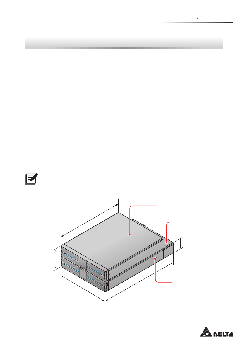
2.2 Exterior & Dimensions
The product that you receive is composed of three parts, a UPS, a battery pack and
a PDB (Power Distribution Box). Please refer to Figure 2-1 and Figure 2-2.
NOTE :
When handling or moving the product, please note that the force area of the
product is at the bottom of the battery pack, but not at the PDB.
UPS
565mm
176mm
(Figure 2-1: Standard Runtime Model - 5/ 6KVA Exterior & Dimensions)
ESC
BATTERY PACK
440mm
665mm
5
PDB
88mm
Battery Pack
Page 10
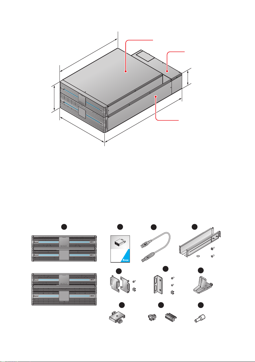
UPS
565mm
PDB
130mm
218mm
ESC
BATTERY PACK
440mm
750mm
Battery Pack
(Figure 2-2: Standard Runtime Model - 8/ 10KVA Exterior & Dimensions)
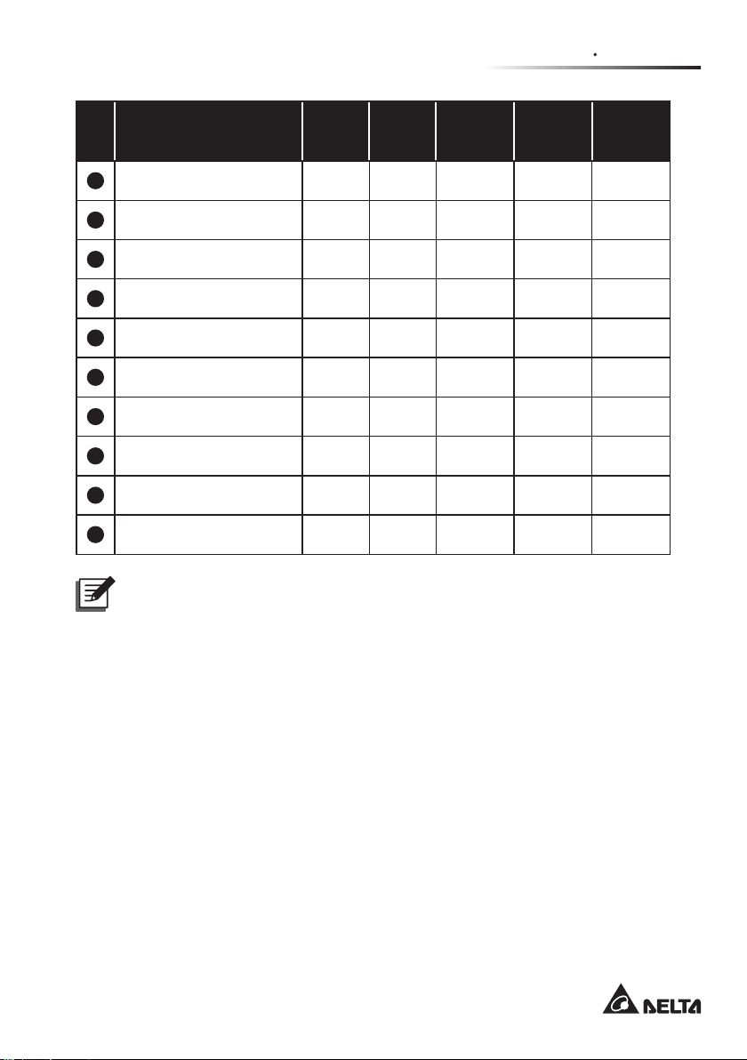
2.3 Package List
The package contains the following items. Please check if any item is missing. If
there is anything missing, please contact the dealer immediately.
Models: UPS502R2RT0B0B8/ UPS602R2RT0B0B8/ UPS802R2RT0B0B8/
UPS103R2RT0B0B8/ UPS502R2RT0B035/ UPS602R2RT0B035/
UPS802R2RT0B035/ UPS103R2RT0B035
1 2
3
4
5/ 6kVA
8/ 10kVA
Amplon RT Series
ESC
BATTERY PACK
ESC
BATTERY PACK
ESC
BATTERY PACK
The power behind competitiveness
Delta UPS - Amplon Family
RT Series, Single Phase
5/ 6/ 8/ 10 kVA
User Manual
www.deltapowersolutions.com
5
×
× 2
× 1×
1
8 9
×
4 or
×
6
6
× 4
× 8× 8
6
×
6
x 2
4
×
4
×
4
7
×
4
10
×
1
×
1
×
6
Page 11
Chapter 2 Introduction
No. Item
1
UPS 1 PC 1 PC 1 PC 1 PC 1 PC
2
User Manual 1 PC 1 PC 1 PC 1 PC 1 PC
3
USB Cable 1 PC 1 PC 1 PC 1 PC 1 PC
4
Rail Kit 1 SET 1 SET 1 SET N/A N/A
5
Bracket Ear for PDB 1 SET 1 SET 1 SET 1 SET 1 SET
6
Bracket Ear for UPS 1 SET 1 SET 1 SET 1 SET 1 SET
7
Tower Stand 4 PCS 4 PCS 4 PCS 4 PCS 4 PCS
8
Tower Stand Expander 4 PCS 4 PCS 6 PCS 4 PCS 6 PCS
9
Pluggable Terminal 2 PCS 2 PCS 2 PCS 2 PCS 2 PCS
10
Cord End Terminal N/A 6 PCS 6 PCS 6 PCS 6 PCS
5kVA
(0B8)
6kVA
(0B8)
8/ 10kVA
(0B8)
5/ 6kVA
(035)
NOTE :
1. If there is any damage or anything missing, please immediately contact
the dealer from whom you purchased the unit.
2. If the UPS needs to be returned, carefully repack the UPS and all of the
accessories using the original packing material that came with the unit.
8/ 10kVA
(035)
7
Page 12
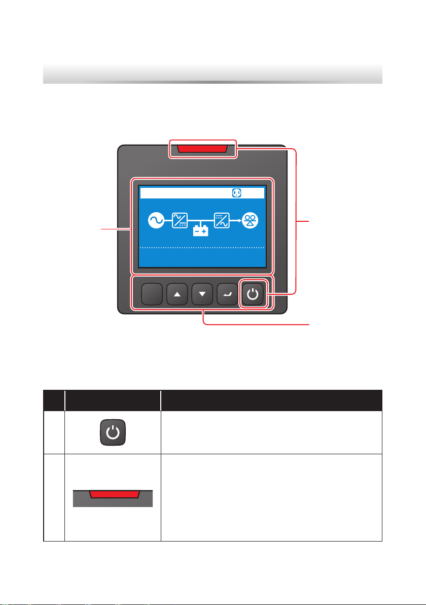
Chapter 3 : Operation Panel
On the front panel of the UPS, you’ll see two LED indicators, a LCD display, and
multi-function buttons.
3.3
LCD Display
ONLINE
%
100
Input
Output
ESC
232.0V 50.0Hz
232.0V 50.0Hz
(Figure 3-1: Operation Panel)
1
%
75
3.1 LED Indicators
No. LED Description
1
2
1. ON: The output is protected.
2. OFF: The output is not protected.
1. ON: The UPS detects an internal fault or an
environmental fault.
2. OFF: The UPS is in normal state.
3. Flashing: The UPS shows the warning message(s).
Please check the corresponding warning
message(s) in Chapter 11: Troubleshooting.
3.1
LED Indicators
3.2
Multi-function
Buttons
Amplon RT Series
8
Page 13
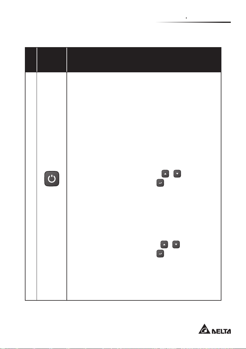
3.2 Multi-function Buttons
Multi-
No.
function
Button
The button has multiple functions. Please refer to the following
for detailed information.
1. Turn-on
z
z
In standby/ bypass mode, press and hold the button for 3
seconds, release it after you hear one beep and the UPS
will run in on-line mode.
z
z
Cold start: When there is no AC input, press and hold the
button for 3 seconds, release it after you hear one beep
and the UPS will run in battery mode.
2. Turn-o
z
z
In on-line mode, (1) press and hold the button for 3
seconds, (2) release it after you hear one beep, (3) use
the Scrolling UP or Down button
1
ON/ OFF
Button
and (4) press the Enter button
tion. After that, the inverter will be off and the UPS will
transfer to run in standby or bypass mode.
The UPS will keep charging the batteries when the UPS
is in standby/ bypass mode. To fully turn o the UPS, it is
advised to disconnect the UPS from the AC power.
z
z
In battery mode, (1) press and hold the button for 3
seconds, (2) release it after you hear one beep, (3) use
the Scrolling UP or Down button (
and (4) press the Enter button (
tion. After that, the UPS will be turned o.
3. Fault Clear
z
z
When the UPS has a fault condition, press and hold the
button for 3 seconds, release it after you hear one beep
and the UPS will try to clear the fault condition.
Description
Chapter 3 Operation Panel
(
/ )
to select 'Yes',
to conrm your selec-
)
(
) to select ‘Yes’,
/
) to conrm your selec-
9
Page 14

No.
2
Multi-
function
Button
Enter
Button
Description
NOTE :
1. When the UPS clears the fault condition, it
means that the buzzer/ warning message has
been turned o. To eliminate the fault detected,
please refer to Chapter 11: Troubleshooting
for relevant solutions.
2. The function mentioned above is only applicable to the condition when the UPS has a
fault situation and the inverter is o.
The button has multiple functions. Please refer to the following
for detailed information.
1. Entering into the setup mode
In the Main Screen (that shows the current operation mode),
press the button for 0.1 second and the UPS will enter into
the Main Menu (setup mode). Please refer to Chapter 9:
LCD Display & Settings.
2. Selecting and conrming the parameter in setup mode
In setup mode, press the button to choose the parameter
you want to change, and the parameter will ash. Press the
Scrolling Up or the Scrolling Down button to change the
parameter and press the button again to conrm the change.
3
Scrolling
Up Button
Amplon RT Series
The button has multiple functions. Please refer to the following
for detailed information.
1. Scrolling Up/ Increasing Number
z
z
In the Main Screen, press the button for 0.1 second and
the UPS will directly enter into the Measurement Menu’s
level 3 (see Figure 9-1: Menu Tree), which contains
related Output information.
z
z
In setup up mode, the button is used to navigate the setting items. Press the button for 0.1 second to go to the
previous setting item.
10
Page 15

No.
3
4
Multi-
function
Button
Scrolling
Up Button
Scrolling
Down
Button
Chapter 3 Operation Panel
Description
z
z
The button is also used to navigate or set up the setting
parameter. Press the button for 0.1 second to go to the
previous display or to increase a number. If the button
is pressed for more than 2 seconds, the number will be
increased single digit every 0.2 second automatically until
the button is released or the number reaches its highest
value.
2. LCD Reset
z
z
Press the Scrolling Up and the Scrolling Down buttons
together for 3 seconds to reset the LCD display.
The button has multiple functions. Please refer to the following
for detailed information.
1. Scrolling Down/ Decreasing Number
z
z
In the Main Screen, press the button for 0.1 second and
the UPS will directly enter into the Measurement Menu’s
level 3 (see Figure 9-1: Menu Tree), which contains
related Output information.
z
z
In setup up mode, the button is used to navigate the setting items. Press the button for 0.1 second to go to the
next setting item.
z
z
The button is also used to navigate or set up the setting
parameter. Press the button for 0.1 second to go to the
next display or to decrease a number. If the button is
pressed for more than 2 seconds, the number will be decreased single digit every 0.2 second automatically until
the button is released or the number reaches its lowest
value.
2. LCD Reset
z
z
Press the Scrolling Up and the Scrolling Down buttons
together for 3 seconds to reset the LCD display.
11
Page 16
Multi-
No.
5
function
Button
ESC
Escape
Button
The button has multiple functions. Please refer to the following
for detailed information.
z
z
Back to the Previous Menu Level
In setup mode, press the button for 0.1 second to go back to
the previous menu level.
Description
NOTE :
If the LCD display goes dim, press any button mentioned above for 0.1
second to wake up the LCD display and enable each button function.
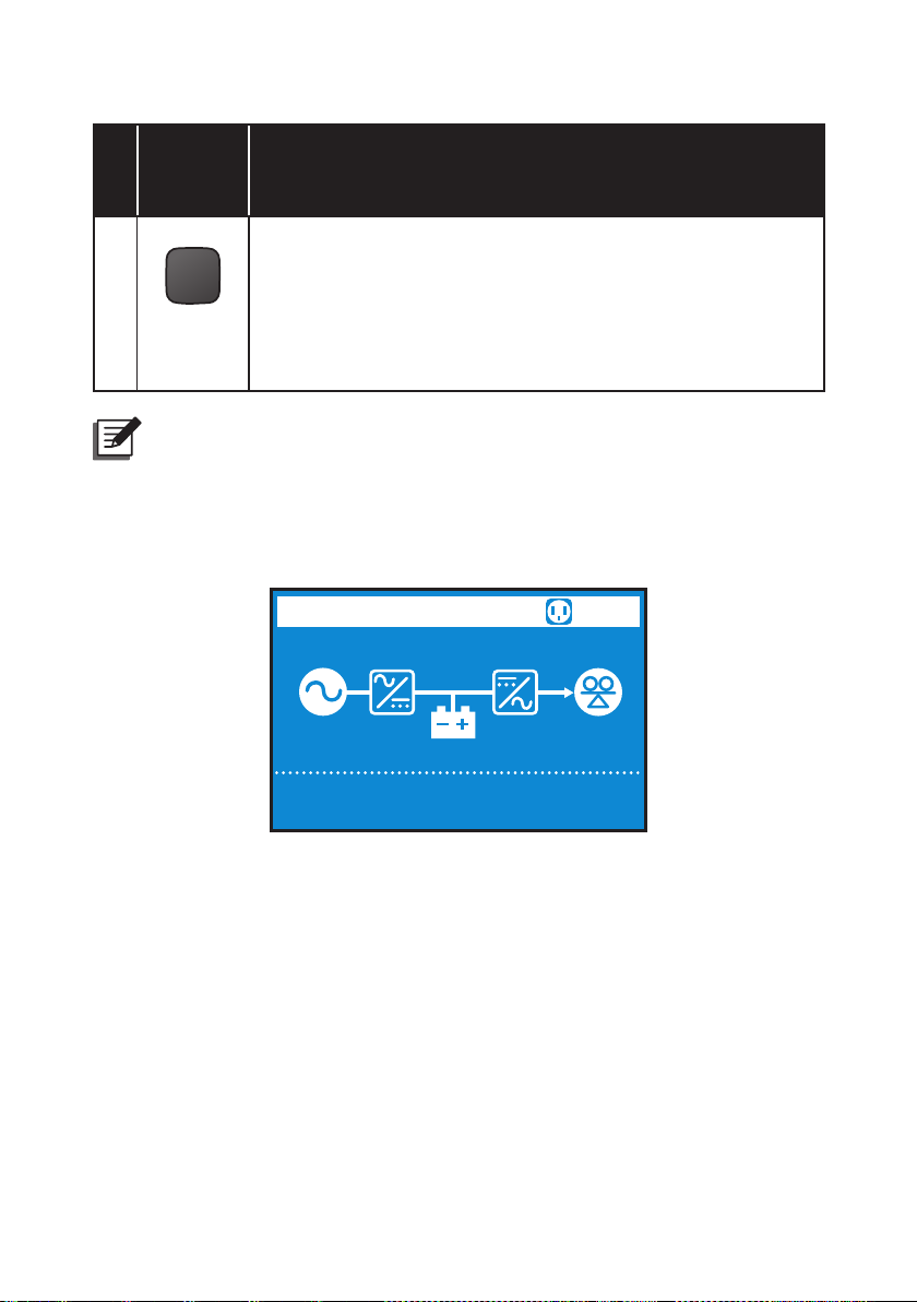
3.3 LCD Display
Amplon RT Series
ONLINE
Input
Output
100
232.0V
232.0V
12
%
50.0Hz
50.0Hz
1
75
%
Page 17
Chapter 3 Operation Panel
1
1
100
%
100
%
75%
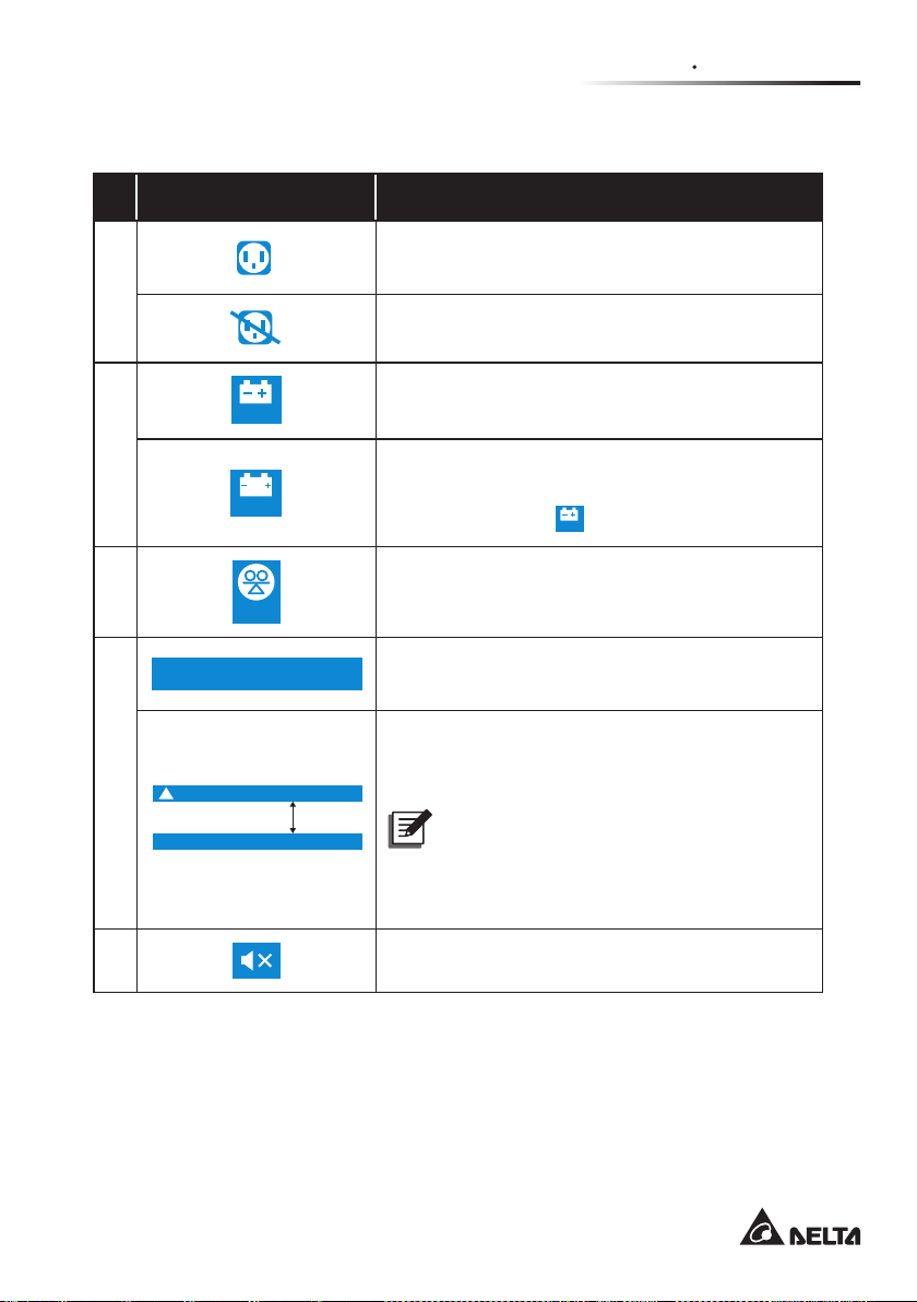
3.3.1 Icon/ Display Denition
No. Icon/ Display Description
1
2
3
Input
Output
4
Battery disconnected
0x1003
!
X
232.0V 50.0Hz
232.0V 50.0Hz
5 seconds
Indicates that the load bank status is ON.
Indicates that the load bank status is OFF.
Indicates the battery capacity level.
Indicates that the battery is abnormal and needs
replacement. If the battery is abnormal, the bat-
tery capacity icon
(
will be o.
)
Indicates the load level (%).
When the UPS runs normally, the display will
show the input/ output voltage and frequency.
When the UPS has abnormalities or is in fault
condition, the display will show an error code
and its corresponding fault or warning message.
NOTE :
The error code and the fault/ warning
message will appear alternatively for
every 5 seconds.
5
Indicates that the buzzer is muted.
13
Page 18
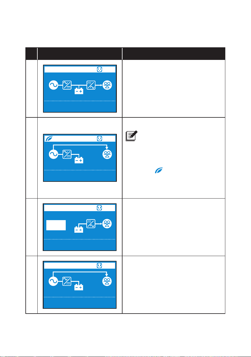
3.3.2 Operation Mode Diagram Denition
ECO
No. Diagram Description
1
2
3
ONLINE
Input
Output
ECO
Input
Output
BATTERY
Runtime
168
min
Input
Output
100
232.0V
232.0V
100
232.0V
232.0V
100
0.0V
230.0V
%
%
%
50.0Hz
50.0Hz
50.0Hz
50.0Hz
0.0Hz
50.0Hz
1
75
Indicates ONLINE mode.
%
Indicates ECO mode.
NOTE :
1
In ECO mode, the diagram’s
power ow will change according
to the UPS input voltage and
75
%
frequency. However, the ECO
icon (
) shown on the
upper-left corner will not change
even if the UPS transfers to online
mode or battery mode.
1
75
Indicates BATTERY mode.
%
4
Amplon RT Series
BYPASS
Input
Output
100
232.0V
232.0V
%
50.0Hz
50.0Hz
1
75
Indicates BYPASS mode.
%
14
Page 19
Chapter 3 Operation Panel
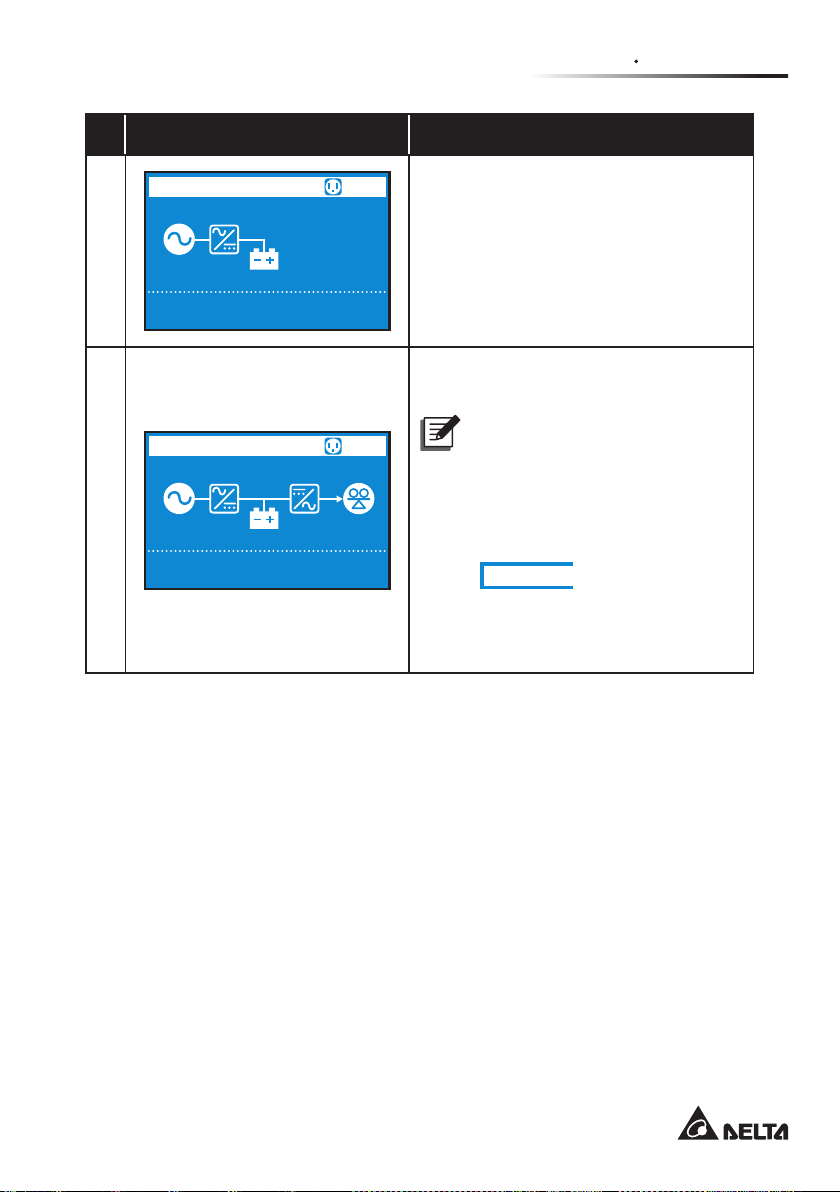
No. Diagram Description
5
6
STANDBY
Input
Output
Freq. Conv.
Input
Output
100
232.0V
0.0V
100
232.0V
232.0V
%
%
50.0Hz
0.0Hz
50.0Hz
50.0Hz
1
Indicates AC STANDBY mode.
Indicates Frequency Conversion
mode.
NOTE :
1
In Frequency Conversion mode,
the diagram’s power ow will
change according to the UPS
75
%
input voltage and frequency.
However, the text Freq. Conv.
(
Freq. Conv.
) shown on the
upper-left corner will not change
even if the UPS transfers to
battery mode.
15
Page 20
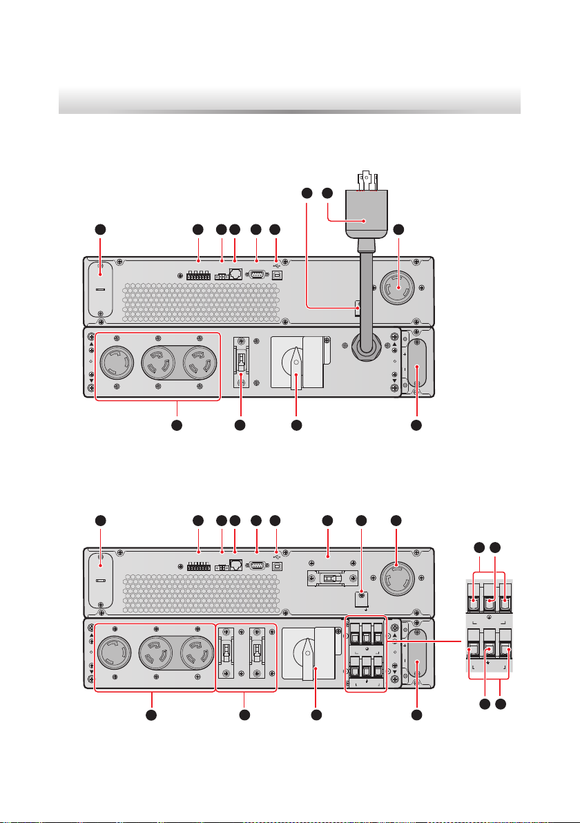
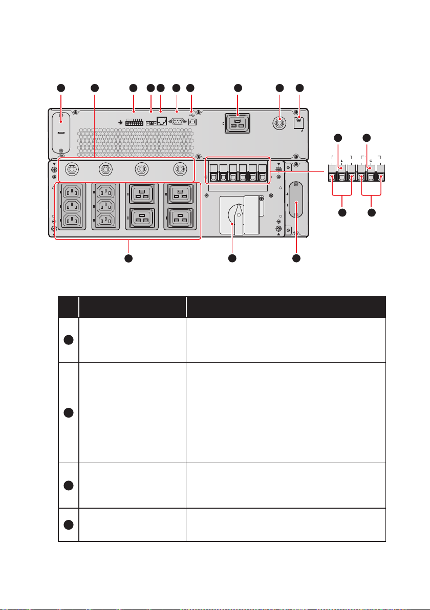
Chapter 4 : Rear Panel
NORMAL
EXTERNAL BATT. CONNECTOR 192V DC 29A
NORMAL
EXTERNAL BATT. CONNECTOR 192V DC 35A
z
z
Model: UPS502R2RT0B0B8
1 2 3
DRY CONTACT
MINI SLOT
OUTPUT SOCKET-3
24A MAX. PER OUTLET
OUTPUT SOCKET-2
20A MAX.
10
z
z
Model: UPS602R2RT0B0B8
1 2 3
DRY CONTACT
MINI SLOT
17
8
4 5 6
RS-232
RS-485
REPO
P2P3P4P1
MANUAL BYPASS SWITCH
WARNING:
OPENING THIS COVER PLATE WILL CAUSE
ONLY AUTHORIZED SERVICE PERSONNEL
CAN OPEN AND OPERATE IT.
OUTPUT BREAKER-2
250V AC 20A
7
INVERTER SHUTDOWN.
11 12
(Figure 4-1: 5kVA Rear Panel)
4 5 6
RS-232
RS-485
REPO
P2P3P4P1
MANUAL BYPASS SWITCH
7
OUTPUT BREAKER-1
250V AC 30A
L6-30P
9
OUTPUT SOCKET-1
29A MAX.
TMOV
AC I NPU T
98
16
15
OUTPUT SOCKET-1
30A MAX.
TMOV
L
1
AC INPUT
L2
Amplon RT Series
OUTPUT SOCKET-3
29A MAX.
L
L2
1
AC INPUT
WARNING:
OPENING THIS COVER PLATE WILL CAUSE
ONLY AUTHORIZED SERVICE PERSONNEL
CAN OPEN AND OPERATE IT.
OUTPUT BREAKER-3
OUTPUT SOCKET-2
20A MAX.
10
250V AC 30A
OUTPUT BREAKER-2
7
250V AC 20A
INVERTER SHUTDOWN.
L1 L2
UPS OUTPU T
11
12
L1 L2
UPS OUTP UT
13
14
(Figure 4-2: 6kVA Rear Panel)
16
Page 21
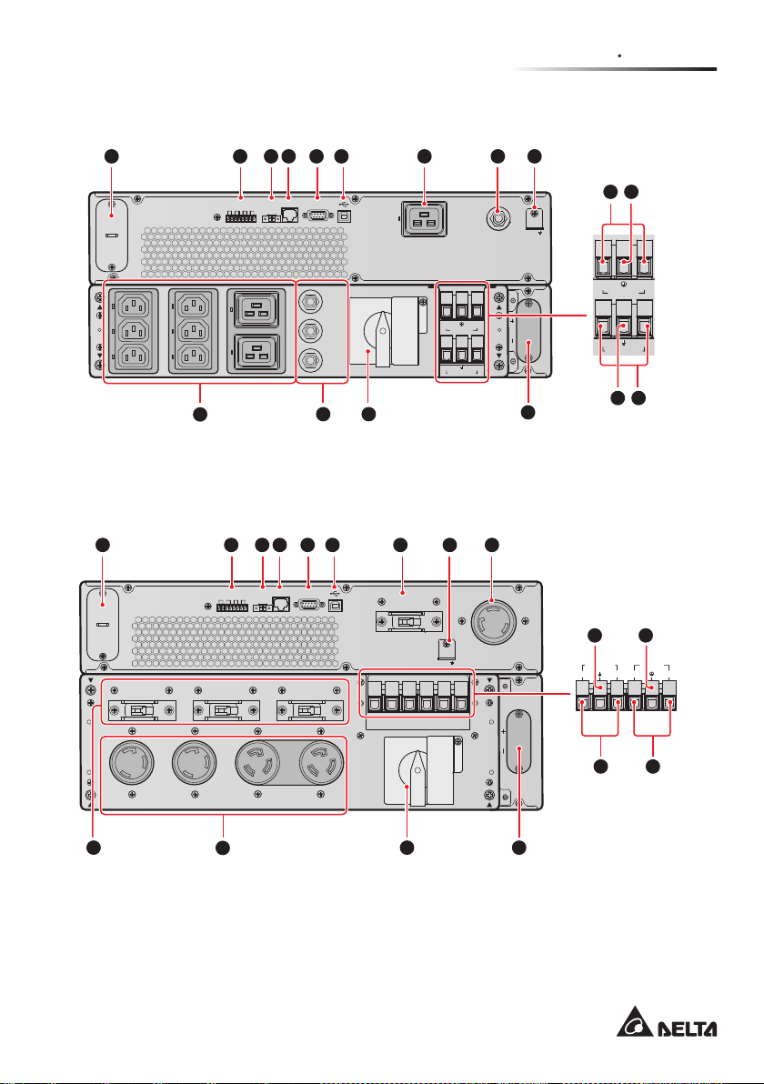
z
NORMAL
NORMAL
z
Models: UPS502R2RT0B035 & UPS602R2RT0B035
Chapter 4 Rear Panel
1 2 3
DRY CONTACT RS-485REPO
MINI SLOT
OUTPUT SOCKET-4 / 10A MAX. PER OUTLET
OUTPUT SOCKET-3 / 10A MAX. PER OUTLET
10
4 5 6
P2P3P4P1
RS-232
MANUAL BYPASS SWITCH
OUTPUT
BREAKER-2
250V AC 25A
OUTPUT
BREAKER-3
250V AC 20A
OUTPUT
BREAKER-4
250V AC 20A
OUTPUT SOCKET-2 / 16A MAX. PER OUTLET
11
7
9 8
OUTPUT SOCKET-1
16A MAX.
WARNING:
OPENING THIS COVER PLATE WILL CAUSE
ONLY AUTHORIZED SERVICE PERSONNEL
CAN OPEN AND OPERATE IT.
INVERTER SHUTDOWN.
(Figure 4-3: 5kVA/ 6kVA Rear Panel)
z
z
Models: UPS802R2RT0B0B8 & UPS103R2RT0B0B8
1 2 3
DRY CONTACT RS-485REPO
MINI SLOT
OUTPUT BREAKER-4
250V AC 30A
OUTPUT BREAKER-3
250V AC 30A
4 5 6 7
P2P3P4P1
RS-232
OUTPUT BREAKER-2
250V AC 20A
OUTPUT BREAKER-1
250V AC 30A
TMOV
AC IN PUT
UPS OU TPU T
8
N L
N L
7
OUTPUT BREAKER-1
250V AC 20A
9
OUTPUT SOCKET-1
30A MAX.
161315
TMOV
N L
AC I NPUT
L
N
EXTERNAL BATT. CONNECTOR 192V DC 35A
12
UPS O UTP UT
14
13
15
UPS OU TPUT AC INP UT
L2 L1 L1 L2
14
16
OUTPUT SOCKET-4
30A MAX.
7
OUTPUT SOCKET-3
30A MAX.
OUTPUT SOCKET-2
20A MAX.
10
MANUAL BYPASS SWITCH
WARNING:
OPENING THIS COVER PLATE WILL CAUSE
ONLY AUTHORIZED SERVICE PERSONNEL
CAN OPEN AND OPERATE IT.
INVERTER SHUTDOWN.
11
EXTERNAL BATT. CONNECTOR 240V DC 46A
12
(Figure 4-4: 8kVA/ 10kVA Rear Panel)
17
Page 22
z
NORMAL
z
Models: UPS802R2RT0B035 & UPS103R2RT0B035
P2P3P4P1
OUTPUT BREAKER-3
250V AC 25A
OUTPUT SOCKET-3
16A MAX. PER OUTLET
4 5 6 77
RS-232
OUTPUT BREAKER-2
250V AC 25A
OUTPUT SOCKET-2
16A MAX. PER OUTLET
MANUAL BYPASS SWITCH
OUTPUT SOCKET-1
16A MAX.
11
TMOV
OUTPUT BREAKER-1
250V AC 20A
WARNING:
OPENING THIS COVER PLATE WILL CAUSE
ONLY AUTHORIZED SERVICE PERSONNEL
CAN OPEN AND OPERATE IT.
INVERTER SHUTDOWN.
12
1 2 3
DRY CONTACT RS-485REPO
MINI SLOT
250V AC 20A
OUTPUT BREAKER-4
250V AC 20A
OUTPUT SOCKET-4
10A MAX. PER OUTLET
OUTPUT BREAKER-5
OUTPUT SOCKET-5
10A MAX. PER OUTLET
10
(Figure 4-5: 8kVA/ 10kVA Rear Panel)
No. Item Functions
Connects to a Mini SNMP IPv6 / Mini Relay I/
1
MINI Slot
O/ Mini MODBUS card. For more information,
please refer to 5.3 MINI Slot.
1. Output dry contacts: Receive the UPS’s
event information to indicate the UPS
status or internal messages.
2
Dry Contacts
2. Input dry contacts: Let the UPS to receive
external control signals.
3. For more information, please refer to 5.5
Dry Contacts.
89
13
15
UPS OU TPUT
EXTERNAL BATT. CONNECTOR 240V DC 46A
14
N L
AC IN PUT
L N
16
Amplon RT Series
3
REPO Port
4
RS-485 Port
When emergency events occur, it can shut
down the UPS safely and immediately. Please
refer to 5.2 REPO Port for details.
Connects to a computer so you can monitor
the UPS status.
18
Page 23
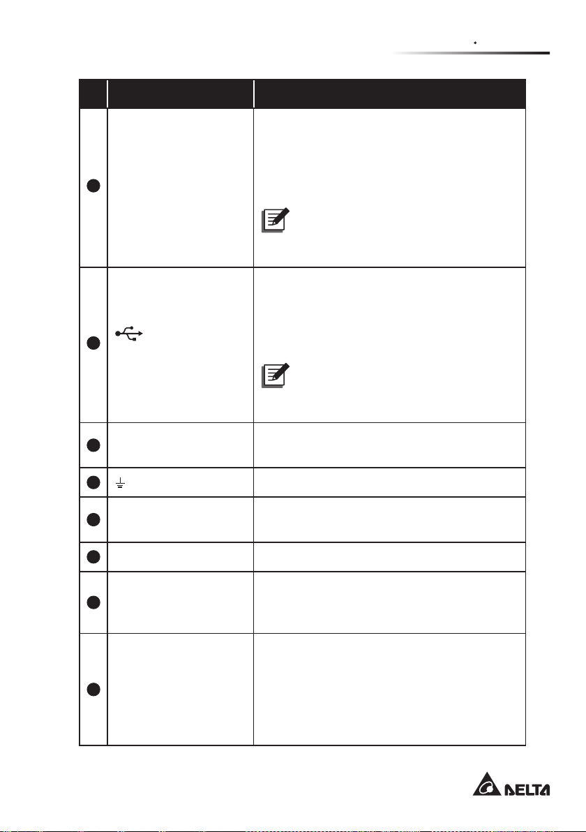
No. Item Functions
Connects to a computer so you can build up
RS-232 communication, congure the UPS
and upgrade the UPS rmware.
5
RS-232 Port
Please refer to 5.1 RS-232 Port for more
information.
NOTE :
The USB port and the RS-232 port
must not be used simultaneously.
Connects to a computer so you can monitor
the state of the UPS, congure the UPS
parameters and update the management
6
(USB Port)
software. Please refer to 5.4 USB Port for
more information.
NOTE :
The USB port and the RS-232 port
must not be used simultaneously.
Chapter 4 Rear Panel
7
Output Breaker(s)
8
Output Socket (with
9
load bank function)
10
Output Sockets Connect to the loads.
Manual Bypass
11
Switch
Prevent(s) the output socket from damage
caused by overload.
For input TMOV’s grounding.
Connects to the loads.
Switches the UPS into manual bypass
mode for maintenance without power supply
interruption.
Connects to the external battery pack
(optional).
External Batt.
12
Connector
5K: 192V DC 29A
6K: 192V DC 35A
8K: 240V DC 37A
10K: 240V DC 46A
19
Page 24

No. Item Functions
13
For loads' grounding.
UPS Output Terminal
Block* (L1 & L2 for
14
sux B8 model; L & N
Connects to the loads.
for sux 35 model)
15
For UPS grounding.
AC Input Terminal
Block* (L1 & L2 for
16
sux B8 model; L & N
Connects to the mains.
for sux 35 model)
17
Input Power Cord Connects to a wall socket.
NOTE :
* Remove the terminal cover plate and you will see the wiring terminal
blocks.
Amplon RT Series
20
Page 25

Chapter 5 Communication Interfaces
Chapter 5 : Communication Interfaces
NOTE :
1. The UPS can still function properly without making the connections below.
2. For the location of the following communication interfaces, please refer to
Figure 4-1~Figure 4-5.
5.1 RS-232 Port
You can use a RS-232 cable (user supplied) to connect the UPS with a computer
and install the UPSentry 2012 software*
z
z
The RS-232 port provides the following functions
1
to check and monitor the UPS status.
1. RS-232 communication (baud rate: 2400/ 9600)
2. UPS conguration
3. Firmware upgrade (baud rate: 9600)
z
z
Pin Assignment
1. PIN 2: TXD <Transmitting Data>
2. PIN 3: RXD <Receiving Data>
3. PIN 5: GND <Signal Ground>
z
z
Hardware
1. Baud Rate: 2400/ 9600bps
2. Data Length: 8 bit
3. Stop Bit: 1 bit
4. Parity: None
NOTE :
1. *1 You can download the software from the following link:
http://www.deltapowersolutions.com/en/mcis/ups-software.php.
2. Do not use the USB port and the RS-232 port simultaneously. If you
connect the USB cable (user-supplied) to the USB port, the RS-232
port will be disabled right away.
21
Page 26

5.2 REPO Port
The REPO port can be connected to an external switch. After the external switch
is turned to the ‘CLOSED’ position, the UPS will switch o the inverter immediately
and cut o the UPS output without transferring to bypass mode.
NOTE :
1. You can use the management software to configure the REPO port as
normally open (NO) or normally closed (NC). The factory default setting is
normally open (NO).
2. The REPO port can also be used for ROO application, which allows you
remotely turn on/ o the inverter. If you need detailed ROO information or
ROO setup service, please contact your local dealer or customer service.
Please note that this port can only be modified by qualified service
personnel.
5.3 MINI Slot
The MINI slot is for mini-size cards. You can install the Mini SNMP IPv6, Mini Relay
I/O, or Mini MODBUS card in this slot to let the system have network communi-
cation, dry contact function, and MODBUS communication respectively.
5.4 USB Port
Please use the provided USB cable to connect the UPS with a computer and install
the UPSentry 2012 software*1 to check and monitor the UPS status. The USB port
has the following functions:
1. HID USB communication
2. UPS conguration with EEPROM programming
3. UPS rmware upgrade
4. Event logs download
5. Dry contacts setup
NOTE :
1. *1 You can download the software from the following link:
http://www.deltapowersolutions.com/en/mcis/ups-software.php.
2. Do not use the USB port and the RS-232 port simultaneously. If you
connect the USB cable (user-supplied) to the USB port, the RS-232
port will be disabled right away.
Amplon RT Series
22
Page 27

Chapter 5 Communication Interfaces
5.5 Dry Contacts
The RT UPS provides one input dry contact for you to receive external control
signals. You can set up relevant items in the Dry Contact Setting screen, which
includes Disable/ ROO/ RPO/ Remote shutdown/ Forced bypass/ On generator.
Besides, there are three congurable output dry contacts for you to receive UPS
events. The output dry contacts are normally open (NO). You can set up relevant
items in the Dry Contact Setting screen, which includes Disable/ On bat/ Low
bat/ Bat fault/ Bypass/ UPS OK/ Load protected/ Load powered/ General alarm/
Overload alarm. Please refer to 9.2.2 Setting Menu and 9.2.4 Maintenance Menu
for relevant information.
5.6 External Battery Connector
The connector is for connection to the external battery pack(s). Please see below
for relevant information.
z
z
Battery
UPS
5kVA/ 6kVA 219.2Vdc 1A (default) 168V±3% 12V × 16 PCS
8kVA/ 10kVA 274Vdc 1.5A (default) 210V±3% 12V × 20 PCS
Charge
Voltage
Charge
Current
Low Battery
Shutdown
The Number
Of Batteries
WARNING:
1. Please refer to the table below to select the charge current for 5kVA/
6kVA/ 8kVA/ 10kVA UPS.
2. If you need to modify the charge current default setting, please
contact your local dealer or customer service.
5kVA/ 6kVA UPS Level 1 Level 2 Level 3 Level 4
Total Battery
Capacity
Charge Current 1A 2A 3A 4A
5~9Ah 9~17Ah 18~30Ah 27~40Ah
23
Page 28

8kVA/ 10kVA UPS Level 1 Level 2 Level 3 Level 4
Total Battery
Capacity
9~17Ah 17~20Ah 20~30Ah 27~40Ah
Charge Current 1.5A 2A 3A 4A
z
z
External Battery Pack
1. To increase the battery backup time, you can connect several external
battery packs to the UPS.
2. Delta external battery pack is optional. Please refer to the Quick Guide,
User Manual or Installation & Operation Guide included in the package of
the external battery pack.
3. When connecting the external battery pack with the UPS, you must install
an appropriate non-fuse DC breaker or the fast-acting fuse that meets the
safety certication. Do not use an AC breaker.
4. The breaker must be a 2-pole non-fuse DC breaker with characteristics of
1-pole 250Vdc, 2-pole 500Vdc and 35kA (or above) DC breaking capacity.
z
z
Battery/ Battery Pack Connection Warnings
1. Only use the same type of batteries from the same supplier. Never use old,
new and dierent Ah batteries at the same time.
2. The number of batteries must meet UPS requirements.
3. Do not connect the batteries in reverse.
4. Use the voltage meter to measure whether the total voltage, after battery
pack connection, is around 12.5Vdc × the total number of batteries.
NOTE :
1. Turn o the UPS and cut o the AC source before performing battery/
2. A battery can present a risk of electric shock and high short-circuit
3. Servicing of batteries and battery packs must be performed or
Amplon RT Series
battery pack replacement.
current.
supervised by qualied service personnel knowledgeable in batteries,
battery packs and the required precautions. Keep unauthorized
personnel away from batteries and battery packs.
24
Page 29

Chapter 5 Communication Interfaces
Maintenance
z
z
Alarm
When any external battery pack connected to the UPS has the following
problems, the UPS system will sound an alarm. Please see the table below.
No.
External Battery
Pack Status
Description
1 Battery Mode The alarm beeps once every 2 seconds.
2 Battery Low Warning The alarm beeps once every 0.5 second.
Battery Missing/
3
Weak Battery/ Battery
The alarm beeps once every 2 seconds.
Replacement
1. Overload_105%~125%: The alarm beeps
4 Overload
once every 2 seconds.
2. Overload_125%~150%: The alarm beeps
once every 0.5 second.
The alarm beeps continuously for 5 seconds
5 Fault
when the UPS detects an internal fault. After
the 5-seconds long beep, the alarm beeps
once every 2 seconds.
NOTE :
*: After reconnecting or replacing the batteries, it might take a while for
the UPS to switch o the alarm automatically. If, after a period of time, the
audible alarm still exists, please manually initiate a battery test. Please
follow the route below to execute the manual battery test in order to clear
the alarm.
Route: press the button
for 0.1 second → tap the icon
Test → select Start Battery Test. Fore relevant information, please refer
to 9.2 Main Menu.
→ select
25
Page 30

Chapter 6 : Installation
Please refer to the system block diagram and related information below for correct
installation.
Bypass
Aux
Power
Inverter relay
Communication
Output
Board
Control
Board
LCD
Board
EMI
Output relay
To A2D/D2D
To inverter
To charger
Output load 1
Output load 2
A2D&D2D
Internal
Battery
Pack
External
Battery
Pack
Input relay
Input
I/P
EMI
Inverter
CHG
6.1 Rack Mounting
Use the included bracket ears and screws to mount the UPS in a rack by following
the procedures below.
1
Attach the included bracket ears to the lateral mounting holes of the UPS. See
Figure 6-1.
ESC
Amplon RT Series
BATTERY PACK
(Figure 6-1: UPS Bracket Ear Installation)
26
Page 31

Chapter 6 Installation
2
Follow steps 1 to 4 to install the UPS in Delta’s rail kit (optional). See Figure
6-2.
1
Step
Step
Step
Step
3
If you want to use a non-Delta rail kit, please only follow step 4 .
: Adjust the length of the rail according to the rack.
2
: Tighten the nuts.
3
: Fix the rail on the rack.
4
: Insert the UPS in the rack and tighten the screws.
NOTE :
4
ESC
BATTERY PACK
1
2
3
(Figure 6-2: Rack Mounting)
If you need the optional rail kit, please contact your local dealer.
27
Page 32

6.2 Tower Mounting
Use the included tower stands to mount the UPS in an upright tower position by
following the steps below.
1
Assemble the tower stands and the tower stand expanders 1 according to the
size of the UPS (see Figure 6-3 & Figure 6-4).
Tower Stand
× 4 PCS
Tower Stand
Expander × 4 PCS
(Figure 6-3: Assemble the Tower
Stands for 5/ 6kVA UPS)
Pull out the two panels and the two Delta logo nameplates
2
them 90° clockwise
Delta Logo
Nameplate
× 2
Panel
3
and re-insert them (see Figure 6-5).
3
2
× 2
3
ESC
BATTERY PACK
(Figure 6-4: Assemble the Tower
Stands for 8/ 10kVA UPS)
2
Tower Stand
× 4 PCS
Tower Stand
Expander × 6 PCS
, rotate
2
(Figure 6-5: Rotate the Two Panels and Two Delta Logo Nameplates)
Amplon RT Series
28
Page 33

Chapter 6 Installation
3
Carefully lift the whole unit upright 4 with the Delta logo nameplates and the
icons shown on the panels facing up.
Panel
× 2
ESC
BATTERY PACK
Lift Up 90˚
Delta Logo
Nameplate
× 2
(Figure 6-6: Place the Whole Unit Upright)
4
Place the whole unit inside the tower stands 5.
ESC
BATTERY PACK
5
ESC
BATTERY PACK
Facing Up
ESC
BATTERY PACK
(Figure 6-7: Place the Whole Unit inside the Tower Stands)
Leave adequate space (at least 50 cm) around all sides of the unit for good
ventilation.
NOTE :
A minimum of two people are required to execute 3 and 4.
29
Page 34

6.3 PDB Disassembly & Installation
Cover Plate
6.3.1 Precautions Prior to PDB Disassembly
1. The PDB is assembled with the UPS when it is shipped out from the Delta
factory. Disassembly of the PDB must be performed by trained professional
personnel.
2. To carry out UPS maintenance without interrupting its power supply, please
follow the procedures below to turn the PDB’s manual bypass switch to the
Bypass position to let the UPS automatically shut down.
1
Unscrew the screw shown below to remove the cover plate of the manual
bypass switch.
MINI SLOT
D
R
Y
C
P
O
1
N
P
T
2
A
C
P
T
3
P
4
R
E
P
O
R
S
4
8
5
R
S
2
3
2
O
U
T
P
U
T
2
B
5
R
0
E
V
A
A
K
C
E
R
3
-
0A
OU
T
P
U
T
B
2
5
R
0
E
V
A
A
K
C
E
R
3
-
0
4
A
O
U
T
P
U
T
S
3
O
0
C
A
K
M
E
A
T
-
X
4
.
Screw
O
U
T
P
U
T
B
2
5
R
0V
E
A
A
K
C
E
R
3
-
0A
3
O
U
T
P
U
T
S
3
O
0
C
A
K
M
E
A
T
-
X
3
.
OU
T
P
U
T
S
2
OC
0
A
M
U
L1
PS
O
U
T
P
U
T
25
B
R
0V
E
A
A
C
2
0
K
E
A
T
X
2
.
K
E
R
2
A
OPENING THIS COVER PLATE WILL CAUSE
INVERTER SHUTDOWN.
ONLY AUTHORIZED SERVICE PERSONNEL
CAN OPEN AND OPERATE IT.
1
TMO
V
O
U
TP
U
T
SO
3
0
C
A
KE
MAX.
T
-
O
U
T
P
U
T
L2
L1
A
C
I
N
PU
T
L2
1
EXTERNAL BATT. CONNECTOR 240V DC 46A
Amplon RT Series
(Figure 6-8: Remove the Cover Plate of the Manual Bypass Switch)
2
Turn the manual bypass switch to the Bypass position.
MINI SLOT
D
R
Y
C
P
O
1
N
P
T
2
A
C
P
T
3
P
4
R
E
P
O
R
S
4
8
5
R
S
2
3
2
O
U
T
P
U
T
2
B
5
R
0
E
V
A
A
K
C
E
R
3
-
0A
OU
T
P
U
T
B
2
5
R
0
E
V
A
A
K
C
E
R
3
-
0
4
A
O
U
T
P
2
5
O
U
T
P
U
T
S
3
O
0
C
A
K
M
E
A
T
-
X
4
.
O
U
T
P
U
T
S
3
O
0
C
A
K
M
E
A
T
-
X
3
.
Manual Bypass
U
T
B
R
0V
E
A
A
K
C
E
R
3
-
0A
3
O
U
T
P
U
T
25
B
R
0V
E
A
C
OU
T
P
U
T
S
2
OC
0
A
K
M
E
A
T
X
2
.
U
L1
A
K
2
0
A
PS
E
R
2
1
TMO
V
O
U
TP
U
T
SO
3
0
C
A
KE
MAX.
T
-
O
U
T
P
U
T
L2
L1
A
C
I
N
PU
T
L2
1
EXTERNAL BATT. CONNECTOR 240V DC 46A
Switch
(Figure 6-9: Turn the Manual Bypass Switch to the Bypass Position)
30
Page 35

Chapter 6 Installation
3
Remove the battery pack’s front bezel and disconnect the battery terminals
before disassembling the PDB (see Figure 6-10).
ESC
BATTERY PACK
Battery
Terminals
ESC
Battery Pack’s
Front Bezel
(Figure 6-10: Disconnect the Battery Power)
6.3.2 PDB Disassembly
NOTE :
Before PDB disassembly, please ensure that you have followed 6.3.1
Precautions Prior to PDB Disassembly.
1
Unscrew the four screws from the PDB (see Figure 6-11_ 1 ).
2
Disassemble the PDB from the rear of battery pack (see Figure 6-11_ 2 ).
MINI SLOT
D
R
Y
C
P
O
1
N
P
T
2
A
C
P
T
3
P
4
R
E
P
O
R
S
4
8
5
R
S
U
L1
PS
O
U
T
P
U
T
L2
L1
A
C
I
N
PU
T
L2
1
Screw × 4
MINI SLOT
D
R
Y
C
P
O
1
N
P
T
2
A
C
P
T
3
P
4
R
E
P
O
R
S
4
8
5
R
S
2
3
2
O
U
T
P
U
T
2
B
5
R
0
E
V
A
A
K
C
E
R
30A
-
OU
T
P
U
T
B
2
5
R
0
E
V
A
A
K
C
E
R
3
-
0
4
A
O
U
T
P
U
T
B
2
50
R
E
V
A
A
K
C
E
R
3
-
0A
3
O
U
T
P
U
T
B
25
R
0
E
V
A
A
K
C
E
R
20
2
A
O
U
T
P
U
T
S
3
O
0
C
A
K
M
E
T
A
-
X
4
.
O
U
T
P
U
T
S
3
O
0
C
A
K
M
E
T
A
-
X
3
.
OU
T
P
U
T
S
2
OC
0
A
K
M
E
A
T
X
2
.
1
TMO
V
O
U
TP
U
T
SO
3
0
C
A
KE
MAX.
T
-
U
L1
PS
O
U
T
P
U
T
L2
1
L1
A
C
I
N
PU
T
L2
EXTERNAL BATT. CONNECTOR 240V DC 46A
Rear of
Battery Pack
PDB
OU
T
P
U
T
B
2
5
R
0
E
V
A
A
K
C
E
3
0
A
O
U
T
P
U
T
S
3
O
0
C
A
K
M
E
A
T
-
X
4
.
2
R
4
O
U
T
P
U
T
B
2
5
R
0V
E
A
A
K
C
E
R
3
-
0A
3
O
U
T
P
U
T
25
B
R
0V
E
A
A
K
C
E
R
2
-
0
2
A
O
U
T
P
U
T
S
3
O
0
C
A
K
M
E
T
A
-
X
3
.
OU
T
P
U
T
S
2
OC
0
A
K
M
E
A
T
X
2
.
2
3
2
OU
T
P
U
T
2
B
5
R
0
E
V
A
A
K
C
E
R
3
-
0
1
A
TMO
V
O
U
TP
U
T
SO
3
0
C
A
KE
MAX.
T
1
EXTERNAL BATT. CONNECTOR 240V DC 46A
(Figure 6-11: Disassemble the PDB)
31
Page 36

6.3.3 PDB Assembly
1
Align the PDB’s three holes ( 1 ) with the three guideposts ( 2 ) on the rear of
battery pack.
2
Attach the PDB to the rear of the battery pack, and use a cross-head
3
screwdriver (
) and four screws ( 4 ) to rmly attach the PDB to the rear of
battery pack (see Figure 6-12).
MINI SLOT
D
R
Y
C
P
O
1
N
P
T
2
A
C
P
T
3
P
4
R
E
P
O
R
S
4
8
5
R
S
2
3
2
O
U
T
P
U
T
25
B
R
0
E
V
A
A
K
C
E
R
3
0A
1
TMO
V
O
U
TP
U
T
SO
3
0
C
A
KE
MAX.
T
1
EXTERNAL BATT. CONNECTOR 240V DC 46A
2
Guidepost × 3
(Left: 1 & Right: 2)
Hole × 3
(Left: 1 & Right: 2)
Rear of
Battery Pack
Screwdriver
3
OU
T
P
U
T
B
2
5
R
0
E
V
A
A
K
C
E
R
3
-
0
4
A
O
U
T
P
U
T
B
2
50V
R
E
A
A
K
C
E
R
3
-
0A
3
O
U
PDB
4
Screw × 4
T
P
U
3
0
O
T
S
O
C
A
K
M
E
A
T
-
X
4
.
O
U
T
P
U
T
S
3
O
0
C
A
K
M
E
A
T
-
X
3
.
OU
T
P
U
T
S
2
OC
0
A
M
A
X
(Left: 2 & Right: 2)
(Figure 6-12: Assemble the PDB)
U
L1
PS
O
U
T
P
U
U
T
P
U
T
25
B
R
0V
E
A
A
K
C
E
2
0
A
K
E
T
2
.
T
L2
L1
R
2
A
C
I
N
PU
T
L2
NORMAL
OPENING THIS COVER PLATE WILL CAUSE
INVERTER SHUTDOWN.
ONLY AUTHORIZED SERVICE PERSONNEL
CAN OPEN AND OPERATE IT.
1
6.3.4 PDB Rack-installation
If you need to install the PDB on a rack, please follow the steps below.
1
Attach the provided mounting brackets to the PDB using the screws that came
with the brackets.
PDB
O
U
T
P
U
T
B
2
5
R
0
E
V
A
A
K
C
E
R
3
-
0
4
A
O
U
T
P
U
T
S
3
O
0
C
A
K
M
E
T
A
-
X
4
.
Amplon RT Series
O
U
T
P
U
T
B
2
5
R
0
E
V
A
A
K
C
E
R
3
-
0
3
A
O
U
T
P
U
T
2
B
5
R
0
E
V
A
A
K
C
E
R
2
-
0
2
A
O
U
T
P
U
T
S
3
O
0
C
A
K
M
E
T
A
-
X
3
.
O
U
T
P
U
T
S
2
O
0
C
A
K
M
E
A
T
X
2
.
U
L1
PS
O
U
T
P
U
T
L2
L1
A
C
I
N
PU
T
L2
32
O
U
T
P
U
T
B
2
5
R
0
E
V
A
A
K
C
E
R
3
-
0
4
A
O
U
T
P
U
T
B
2
5
R
0
E
V
A
A
K
C
E
R
3
-
0
3
A
O
U
T
P
U
T
2
B
5
R
0
E
V
A
A
K
C
E
R
2
-
0
2
O
U
T
P
U
T
S
3
O
0
C
A
K
M
E
T
A
-
X
4
.
O
U
T
P
3
A
U
T
S
O
0
C
A
K
M
E
T
A
-
X
3
.
O
U
T
P
U
T
S
2
O
0
C
A
K
M
E
A
T
X
2
.
PDB
U
L1
PS
O
U
T
P
U
T
L2
L1
A
C
I
N
PU
T
L2
Page 37

Chapter 6 Installation
2
Attach the provided M5 nuts to the rack. Use the provided M5 screws to rmly
install the PDB on the rack. Ensure that the screws are tightly xed.
O
PDB
U
T
P
U
T
B
2
5
R
0
E
V
A
A
K
C
E
R
3
-
0
4
A
O
U
T
P
U
T
B
2
5
R
0
E
V
A
A
K
C
E
R
3
-
0
3
A
O
U
T
P
U
T
S
3
O
0
C
A
K
M
E
T
A
-
X
4
.
O
U
T
P
U
T
S
3
O
0
C
A
K
M
E
T
A
-
X
3
.
U
L1
PS
O
U
T
P
U
O
U
T
O
U
T
P
U
T
S
2
O
0
C
A
K
M
A
X
.
T
P
L2
U
T
2
B
5
R
0
E
V
A
A
K
L1
C
E
R
2
-
0
2
A
E
T
2
A
C
I
N
PU
T
L2
M5 NUT
× 2 (Left: 1
& Right: 1)
O
U
T
P
U
T
B
2
5
0
V
A
O
U
T
P
U
T
S
3
O
0
C
A
K
M
A
X
.
PDB
R
E
A
K
C
E
R
3
-
0
4
A
O
U
T
P
U
T
B
2
5
R
0
E
V
A
A
K
C
E
R
3
-
0
3
A
E
T
4
O
U
T
P
U
T
S
3
O
0
C
A
K
M
E
T
A
-
X
3
.
O
U
L1
PS
O
U
T
P
U
O
U
T
P
U
2
5
0
U
T
P
U
T
S
2
O
0
C
A
K
M
E
A
T
X
.
T
L2
T
B
R
E
V
A
A
K
C
2
L1
E
R
2
-
0
2
A
A
C
I
N
PU
T
L2
6.4 Battery/ Battery Pack Replacement
NOTE :
1. Turn off the UPS and cut off the AC source before performing battery/
battery pack replacement.
2. A battery can present a risk of electric shock and high short-circuit
current.
3. Servicing of batteries and battery packs must be performed or supervised
by qualied service personnel knowledgeable in batteries, battery packs
and the required precautions. Keep unauthorized personnel away from
batteries and battery packs.
Replace the battery/ battery pack by following the procedures below.
1
Unscrew the screws and remove the battery pack’s front bezel 1.
M5 Screw
× 2 (Left: 1
& Right: 1)
2
Disconnect the battery terminals 2.
3
Use the Phillips screwdriver to remove the screws from the protective cover
3
located in front of the battery
.
33
Page 38

4
Pull out the battery from the left battery compartment and insert a new
one. Follow the same procedure to replace the battery in the right battery
compartment
4
.
1
3
NOTE :
A minimum of two people are required to execute 3 and 4.
2
ESC
ESC
BATTERY PACK
4
ESC
ESC
5
Reassemble the battery pack in reverse order.
Amplon RT Series
34
Page 39

Chapter 7 Connection and Wiring
Power
Chapter 7 : Connection and Wiring
7.1 UPS Connection Warnings
1
When connecting the UPS to the mains and the loads, it is highly recom-
mended that you install the protective devices. Please refer to the table and
diagram below.
UPS Power Rating Suggested Protective Device
5kVA D curve-30A circuit breaker DELIXI
6kVA D curve-50A circuit breaker DELIXI
8/ 10kVA D curve-80A circuit breaker DELIXI
MINI SLOT
D
R
Y
C
P
O
1
N
P
T
2
A
C
P
T
3
P
4
R
E
P
O
R
S
4
8
5
R
S
2
3
2
O
U
T
P
U
T
2
B
5
R
0
E
V
A
A
KE
C
R
3
0
1
A
TMO
V
O
U
TP
U
T
SO
3
0
C
A
KE
MAX.
T
-
O
U
T
P
U
T
L2
L1
A
C
I
N
PU
T
L2
1
EXTERNAL BATT. CONNECTOR 240V DC 46A
Output
Protective
Device
Loads
Grounded
Utility AC
O
U
T
P
U
T
B
2
5
R
0
E
V
A
A
K
C
E
R
3
-
0
4
A
O
U
T
P
U
T
2
B
5
R
0
E
V
A
A
K
C
E
R
3
-
0
3
A
O
U
T
P
U
T
B
2
5
R
0
E
V
A
AC
K
E
R
2
-
0
O
U
T
P
U
T
S
O
3
0
C
A
K
M
E
T
A
-
X
4
.
O
A
U
T
P
U
T
S
3
O
0
C
A
KE
M
T
A
-
X
3
.
U
L1
2
PS
OPENING THIS C
INVERTER SHUTDOWN.
ONLY AUTHORIZED SERVICE PERSONNEL
CAN OPEN AND OPERATE IT.
Grounded
Input
Protective
Device
Suggested
Supplier
(Figure 7-1: Wiring Diagram)
2
The protective devices must use approved components that meet safety
certications.
3
The power supplying to the UPS must be single-phase in accordance with the
unit's rating label, and the UPS must be properly grounded.
35
Page 40

7.2 Input/ Output Connection
1
Please see the gures below for input/ output connection.
UPS OUTP UT
L
L N
N
AC INPU T
N
L
AC INPU T
L
N
UPS OUTPUT
5/ 6kVA
(Suffix 35 Model)
L
1
L1 L 2
UPS OUTPUT
(Suffix B8 Model)
AC INPU T
6kVA
L2
8/ 10kVA
(Suffix 35 Model)
UPS OUTP UT AC IN PUT
L2L1 L2L1
8/ 10kVA
(Suffix B8 Model)
2
Cable Selection:
For the specications of input/ output cables, please refer to Table 7-1.
Table 7-1: Specications of Input/ Output Cables
Spec. \ Capacity 5/ 6kVA (Sux: B8) 8/ 10 kVA (Sux: B8)
Input/ Output Cables
(Rating Temperature 90°C)
Tightening Torque
(For AC Wiring)
#8AWG #6AWG
12kgf·cm 25.5kgf·cm
Spec. \ Capacity 5/ 6kVA (Sux: 35) 8/ 10 kVA (Sux: 35)
Input/ Output Cables 6mm
2
10mm
2
Tightening Torque
(For AC Wiring)
12kgf·cm 18kgf·cm
In accordance with National Electrical Codes (NEC), please install the suitable
conduits and cable sleeves.
3
When connecting the input/ output power cords, please observe the following
rules.
Amplon RT Series
36
Page 41

Chapter 7 Connection and Wiring
1. Turn of the UPS and cut o both AC source and the battery source before
connection.
2. Calculate the power consumption of the loads to avoid an overload
condition.
3. Ensure that the screws are tightly fixed after connection. Please refer to
Table 7-1.
4
Backfeed Protection:
When the UPS runs in battery mode or during AC power failure, the UPS’s
inner voltage or energy might be fed back to the input terminals, either directly
or via a leakage loop. To avoid the risk of electric shock resulted from the
backfeed, installation of a backfeed protection device between the AC input
and the UPS is highly recommended.
NOTE :
1. The UPS doesn’t have any built-in backfeed protection device.
Installation of the backfeed protection device between the AC input
and the UPS is highly recommended.
2. If there is no backfeed protection device installed between the AC
input and the UPS, please (1) attach a warning label on the switch
or breaker that controls the AC power supplying to the UPS, and (2)
check if any hazardous voltage exists on any terminals connected to
the AC power. The warning label shall carry the following wording or
equivalent.
Before Working on This Circuit
-Isolate Uninterruptible Power System (UPS)
-Then check for Hazardous Voltage between all terminals
z
z
Backfeed Protection Device Requirements:
including the protective earth.
Risk of Voltage Backfeed
Suggested Backfeed
UPS
Protection Device
Rating Voltage/ Current
5/ 6kVA
208/ 220/ 230/ 240Vac
40A
37
Suggested Model
No.
AF52-30-13 (ABB)
Page 42

UPS
Suggested Backfeed
Protection Device
Rating Voltage/ Current
Suggested Model
No.
8/ 10kVA
z
z
Control Relay Requirements:
208/ 220/ 230/ 240Vac
65A
AF52-30-13 (ABB)
Breaking Capacity 240Vac/ 5A
Contact Form Normally Closed (NC)
Coil 12Vdc/ <0.5A
Suggested Model No. HF13F-012-1Z1T
z
z
Backfeed Protection Wiring Diagram:
Please refer to the diagram below to install the backfeed protection device
between the AC input and the UPS.
Contactor
L (L1)
N (L2)
L (L1)
N (L2)
UPS
Dry
Contact
Amplon RT Series
Coil
Control Relay
DC 12V
38
Page 43

Chapter 8 Operation
100
%
Chapter 8 : Operation
8.1 Start-up
NOTE :
1. Before start-up, ensure that the batteries are fully charged. Before
using the UPS for the first time, please check the battery capacity and
the charging settings. Make sure that you charge the batteries until the
battery capacity percentage shown on the UPS’s LCD is 100%
2. The configurable internal battery string quantity ranges from 16 to 22.
Please make sure that the actual quantity of battery strings are the same
as that congured on the LCD. Set up the corresponding charge current
based on the total battery amp-hour.
3. If the UPS connects to an inductive load, the inrush current (initial surge
current) may restart the inverter. To avoid this situation, please turn on the
inductive load in bypass mode before starting up the inverter.
z
z
Start-up with AC Input
1
Verify if the UPS’s input cord meets with N, L & G of the wall socket and the
utility AC power works normally.
.
(
)
2
Switch on the input protective device (see Figure 7-1) installed between
the UPS and the utility AC power. After that, the UPS will enter into the
Initial Setting Screen (please refer to 9.1 Initial Setting Screen for more
information).
Press and hold
3
the ON/ OFF button (
for 3 seconds to start up the
)
UPS. Release the button after you hear one beep and the UPS will start up.
After the UPS performs self-diagnosis, the UPS will run in ON-LINE mode.
39
Page 44

Press and hold the button
BYPASS
%
100
Input
Output
232.0V
232.0V
50.0Hz
50.0Hz
for 3 seconds and release it
after you hear one beep.
Self Diagnosis
In Progress...
ONLINE
1
75
%
4
Once the UPS runs normally, switch on the output protective device (see
Figure 7-1) installed between the UPS and the loads.
z
z
Start-up with Battery (Cold-start)
1
Please check the ‘+’and ‘-’ poles of the batteries and ensure that wiring is
correct.
2
Turn on the battery breaker.
When there is no AC input, press and hold the ON/ OFF button
3
seconds to start up the UPS. Release the button after you hear one beep
and the UPS will start up. After the UPS performs self-diagnosis, the UPS
will run in BATTERY mode.
Amplon RT Series
0x1012
!
Battery Test Fail
X
40
75%
for 3
(
)
Page 45

Press and hold the button
for 3 seconds and release it
after you hear one beep.
Self Diagnosis
In Progress...
Chapter 8 Operation
BATTERY
Runtime
168
min
Input
Output
4
Once the UPS runs normally, switch on the output protective device (see
100
0.0V
230.0V
%
0.0Hz
50.0Hz
1
75
%
Figure 7-1) installed between the UPS and the loads.
NOTE :
To prevent the UPS from activating the overload protection mechanism
during start-up process, please turn on the high-power loads first and
then low-power loads.
8.2 Turn-o
1
Make sure all of the loads connected to the UPS are o.
2
(1) Press and hold the ON/ OFF button (
you hear one beep, (3) use the Scrolling UP or Down button (
'Yes'
select
3
Switch o the input protective device (see Figure 7-1) and output protective
, and (4) press the Enter button (
device (see Figure 7-1).
) for 3 seconds, (2) release it after
/
) to conrm your selection.
) to
4
After the LCD backlight goes dim and the fans stop completely, switch o the
battery breaker to ensure that there is no remaining battery power.
41
Page 46

8.3 Operation Mode
z
z
Standby Mode
After the UPS is connected to the utility AC power, it will supply power to the
UPS and the batteries will be charged.
z
z
Online Mode
In on-line mode, the connected loads are supplied by the inverter, which derives
its power from the utility AC power, and the UPS charges the batteries and
provides power protection to its connected loads.
z
z
Bypass Mode
In bypass mode, the critical loads are directly supplied by the utility AC power
and the batteries are charged. The default setting of the UPS is set in BYPASS
mode.
z
z
Battery Mode
When the UPS is operating during a power outage, the batteries provide DC
power, which maintains inverter operation to supply power to the critical loads.
You can install the UPSentry 2012 software (please download from http://www.
deltapowersolutions.com/en/mcis/software-center.php) or install the Mini SNMP
IPv6 card (optional) or the Mini MODBUS card (optional) to monitor and estimate
the battery remaining capacity. For more information about the Mini SNMP IPv6
card (optional) or the Mini MODBUS card (optional), please refer to its user
manual.
z
z
ECO Mode
In ECO mode, when the utility input voltage and frequency are within the range
of rating voltage ±10% and rating frequency ±3Hz, the loads are supplied by the
utility AC power; if out of the range, the loads are supplied by the inverter.
z
z
Frequency Conversion Mode
In Frequency Conversion mode, the UPS output frequency is manually set up.
The system will disable the bypass function and there is no bypass output.
Amplon RT Series
42
Page 47

Chapter 9 LCD Display & Settings
Chapter 9 : LCD Display & Settings
NOTE :
1. Please refer to Chapter 3: Operation Panel to learn how to operate the
operation panel and understand every icon/ diagram denition.
2. Each of the display diagrams shown in this chapter is for reference only.
Actual display depends on the operation of the UPS.
The following flow chart helps you to understand how to navigate each display
screen.
9.1 Initial Setting Screen
When the UPS is powered on at rst time, the LCD display will enter into the Initial
Setting Screen and you can modify language, output voltage, battery parameters
based on actual needs during initial setup. The default settings of language, output
voltage, and battery parameters may vary according to dierent models. Press the
button to continue if there is no special requirement. After you configure the
Language, Date & Time, Output Setting, External Battery Type and External
Battery Capacity settings, the LCD display will move to the Main Screen that
shows the current operation mode.
43
Page 48

Welcome
Page
Output Setting
Prev.
Output Phase:
Voltage:
Frequency:
Next
External Battery Type
Prev.
Standard Battery Pack
P/N:
GES161B105700
Qty:
0
Next
1-Phase
100 V
Auto
Initial Setting
Screen
Date:
Time:
Language
Prev.
English
Next
Date & Time
Prev.
2017 / 10 / 06
18 : 04 : 25
Next
External Battery Capacity
Customer Own Battery Cabinet
Battery Voltage:
Battery Capacity:
STANDBY
Input
Output
Prev.
Next
100
232.0V
0.0V
%
192 Vdc
9 9 9
50.0Hz
0.0Hz
1
Main Screen
(showing
the current
operation mode)
The Initial Setting Screen will no longer appear after initial conguration. Next time,
when the UPS is powered on, the LCD display will show DELTA welcome page for
3 seconds and then directly go to the Main Screen that shows the current operation
mode.
Amplon RT Series
44
Page 49

Welcome Page
Chapter 9 LCD Display & Settings
BYPASS
1
Main Screen
%
75
50.0Hz
50.0Hz
Input
Output
100
232.0V
232.0V
%
9.2 Main Menu
Control
for 0.1 second to enter into the Main
Setting
Maintenance
In the Main Screen, press the button
Menu. You can set up relevant items here.
Main Menu
Measurement
NOTE :
Please note that only qualied service personnel can perform setup actions.
45
Page 50

For setup procedures, please refer to the following:
1
In the Main Menu, select the item you want to configure, press the ENTER
button
Press the button
2
for 0.1 second and the UPS will enter into the setup mode.
for 0.1 second or press the button
for 0.1 second to
navigate the setting items.
Press the button
3
for 0.1 second to choose the parameter that you want to
change, and the parameter will ash.
Press the button
4
for 0.1 second or press the button
for 0.1 second to
increase or decrease the parameter value. If either of the buttons is pressed
for over 2 seconds, the LCD will automatically switch between the selectable
values every 0.2 second until either of the buttons is released or the number
reaches its highest or lowest value.
Press the button
5
to conrm your parameter setup or press the button
to go back to the previous status.
After that, press the button
6
for 0.1 second or press the button
for 0.1
second to move to the previous or the next setting item.
ESC
In setup mode, press the
7
button and the LCD will exit from the setup
mode.
8
In setup mode, if you don’t press any button for more than 5 minutes, the LCD
will exit from the setup mode and go back to the original display automatically.
Please refer to the Menu Tree below for all setting options.
ESC
Amplon RT Series
46
Page 51

Chapter 9 LCD Display & Settings
(Level 1) (Level 1) (Level 1) (Level 1)
Measurement
(Level 2)
Output
Voltage/ Frequency/
(Level 3) (Level 3) (Level 3)
Current/ Watts/
Load/ VA/
Cumulated/ Power
(Level 2)
Input
Voltage/ Frequency
(Level 2)
Bypass Input
Voltage
Frequency
(Level 2)
Battery
Voltage/ Capacity/
Last battery test Runtime/
Charge mode/
Total capacity
Setting
(Level 2)
Output
Output Phase/ Output Voltage/
(Level 3) (Level 3) (Level 3) (Level 3)
Output Frequency/
Output Sync. Freq. Range/
Output Freq. Slew Rate/
Output Mode/ Standby Mode/
Overload Alarm
(Level 2)
Input
Bypass Max. Voltage/
Bypass Min. Voltage
(Level 2)
ECO Mode
ECO Mode/
ECO Max. Voltage/
ECO Min. Voltage
(Level 2)
Parallel
(Level 3)
Redundant UPS/ ID
(Level 2)
On/Off Settings
Energy Saving/
Sleep Mode/
Auto Restart/
Auto Start on AC
Control
(Level 2)
Output
(Level 3)
Outlet Group 1
Bypass
(Level 2)
Charger
(Level 3) (Level 3)
Execute Boost Charge
(Level 2)
Alarm
Clear Prediction Warning
(Level 2)
Battery
Automatic Battery Test/
Deep Discharge Test/
Low Battery Warning Capacity/
(Level 3)
Warning of Remaining Time/
Runtime Limitation/
Charge Mode/
Float Charging Voltage/
Internal Charging Current/
External battery Type/
External Battery Capacity/
Install Date
(Level 2)
General
(Level 3)
Language/ Audible Alarm
LCD Back Light/
Date/ Time
(Level 2)
Outlet Control
(Level 3)
Outlets - Group 1
(Level 2)
Dry Contact Setting
Dry Contact 1 – Input/
(Level 3)
Dry Contact 2 – Output/
Dry Contact 3 – Output/
Dry Contact 4 – Output/
Remote Control
(Level 2)
Component Life Prediction
(Level 3)
Fan Life Prediction
Maintenance
(Level 2)
Test
(Level 3) (Level 3) (Level 3) (Level 3) (Level 3)
Start Battery Test
Deep Discharge Test
Local Output Dry Contact Test
(Level 2)
Battery Aging
Create Discharging Reference
Battery Discharging History
(Level 2)
Reset
Reset Power Usage Calculator
Restore Factory Setting
(Level 2)
Log
Event List
Clear Log
(Level 2)
About
Model Name/ UPS Part No./
UPS Serial No./
UPS Manufacture Date/
UPS Firmware Version/
Battery Summary - Installed/
Battery Summary - Replaced
(Figure 9-1: Menu Tree)
47
Page 52

9.2.1 Measurement Menu
Measurement
Setting
In Main Menu, after selecting
, press the button
to enter into the
Measurement Menu. The Measurement Menu displays the UPS’s status readings,
such as Output, Input, Bypass and Battery information.
Measurement
Control
Setting
Maintenance
Output
Input
Bypass
Battery
9.2.2 Setting Menu
In Main Menu, after selecting
Menu.
Measurement
Control
Setting
Maintenance
, press the button
to enter into the Setting
Output
Input
ECO Mode
Parallel
On/Off Settings
Battery
General
Outlet Control
1 /3
2 /3
Amplon RT Series
3 /3
Dry Contact Setting
Component Life Prediction
48
Page 53

Chapter 9 LCD Display & Settings
You can choose the setup items such as Output, Input, ECO Mode, On/ Off
Settings, Battery, General, Outlet Control, Dry Contact Setting and Component
Life Prediction to set up relevant settings. For more information about the Setting
Menu, please refer to the tables below for each setup item’s relevant default value
and selectable value.
z
z
Output
Setup Items Selectable Value Default
Output Phase 1-phase 1-phase
Output Voltage
Output Frequency
Output Sync.
Freq. Range
Output Freq.
Slew Rate
200V, 208V, 220V,
230V, 240V
Auto* / Converter-50Hz** /
Converter-60Hz**
±0.5/ 1/ 3/ 5Hz ±3Hz
0.5/ 1/ 2/ 3/ 4 Hz/ sec. 1 Hz/sec.
208V for sux B8 model
230V for sux 35 model
Auto
Output Mode Industrial/ IT IT
Standby Mode No output/ Bypass output Bypass output
Overload Alarm 30-105% (one step: 5%) 105%
NOTE :
1. * When the Output Frequency is set as Auto, the output frequency
will vary according to the bypass frequency. If the bypass frequency
is ≥ 55Hz, the Free_Run_Frequency/ Cold_Start_Frequency will be
set as 60Hz.
If the bypass frequency is < 55Hz, the Free_Run_Frequency/ Cold_
Start_Frequency will be set as 50Hz.
2. When the Output Frequency is set as Auto and the Bypass Output
under the Standby Mode item is set as Enable, the bypass output
range will be the same as the Output Sync. Freq. Range.
3. ** When the Output Frequency is set as Converter-50Hz/
Converter-60Hz, the UPS will enter into Frequency Conversion
mode and the bypass output will become Disable.
49
Page 54

z
z
Input
Setup Item Selectable Value Default Value
Bypass Max. Voltage +10/ 15/ 20% +15%
Bypass Min. Voltage -10/ 15/ 20/ 25/ 30/ 35/ 40% -20%
z
z
ECO Mode
Setup Item Selectable Value Default Value
ECO Mode Disable/ Enable Disable
ECO Max. Voltage 5-15% (one step: 1%) +10%
ECO Min. Voltage 5-15% (one step: 1%) -10%
NOTE :
The setup items ECO Max. Voltage and ECO Min. Voltage will only be
shown on the display when ECO Mode is enabled.
z
z
On/ O Settings
Setup Item Selectable Value Default Value
Energy Saving
Sleep Mode
Auto Restart Enable/ Disable Enable
Auto Start on AC Enable/ Disable Disable
NOTE :
In Setting Menu, the sub item Option 1 under the item Energy Saving
cannot be changed.
Amplon RT Series
Option 1*: Enable/ Disable
Option 2: 1-15mins (one step: 1min)
Option 3: 300W-1500W (one step: 100W)
Option 1: Enable/ Disable
Option 2: 10-120mins (one step: 10mins)
50
Disable
10mins
Page 55

z
z
Chapter 9 LCD Display & Settings
Battery
Setup Item Selectable Value Default Value
Automatic Battery Test
No test/ Daily/ Weekly/
Biweekly/ Monthly
No test
Deep Discharge Test 20-90% (one step: 10%) 90%
Low Battery
Warning Capacity
Warning of
Remaining Time
Runtime Limitation
Disable/ 1/ 2/ 3…./ 240
0-95%
(one step: 5%)
0-60mins
(one step: 1min)
(one step: 1min)
10%
2mins
Disable
Charge Mode 2-stage/ 3-stage 2-stage
Float Charging
Voltage
Internal Charging
Current
External Battery Type *
Auto/ Customize
(2.20 - 2.35 V/ cell,
one step: 0.01V)
For 5K/ 6K: 1/ 2/ 3/ 4/ 5/ 6/ 7/ 8
For 8K/ 10K: 1.5/ 2/ 3/ 4/ 5/ 6
Standard battery pack/
Customer own batt. pack
Auto
1A (5K/ 6K)
1.5A (8K/ 10K)
Standard battery pack:
External Battery
Capacity
Part Number Quantity
Customer own batt. pack:
Battery Voltage Capacity
Install date YYYY/ MM/ DD
NOTE :
* When the External Battery Type is set as Standard battery pack, you
need to configure the Part Number and the Quantity of the standard
battery pack(s).
51
Page 56

z
z
General
- Battery
Internal Charging Current
1.5 A
External Battery Type
Standard Battery Pack
Part Number
GES161B151XXX
3 /4
- Battery
Quantity
0
Install Date
2017/11/11
4 /4
When the External Battery Type is set as Customer own batt. pack,
the Part Number and Quantity will be changed accordingly to Battery
Voltage and Total Capacity.
Setup Item Selectable Value Default Value
Language
English/ 简体中文 / 繁體中文 /….
Audible Alarm Enable/ Disable Enable
LCD Back Light Always On/ Auto O Auto o
Date YYYY/MM/DD
Time HH:MM:SS
z
z
Outlet Control
Setup
Item
Outlets -
Selectable Values-
Level 2
Output Reboot
Duration
Selectable Values-
Level 3
Disable/ 5/ 6/
…/ 300
seconds
(one step: 1sec)
Group 1
Load Bank
Runtime Limitation
Disable/ 1/ 2/…/ 240mins
(step: 1min)
English
Default
Value
Disable
Disable
Amplon RT Series
52
Page 57

z
z
Dry Contact Setting
Chapter 9 LCD Display & Settings
Setup
items
Dry Contact
1 - Input
Dry Contact
2 - Output
Dry Contact
3 - Output
Dry Contact
4 - Output
Remote
Control
Selectable
value
Option 1*: Disable/ ROO/ RPO/ Remote
shutdown/ Forced bypass/ On generator
Option 2: 0-999s (step: 1 sec)
Option 3: Normal open/Normal close
Disable/ On bat/ Low bat/ Bat fault/ Bypass/ UPS
OK/ Load protected/ Load powered/ General alarm/
Overload alarm
Disable/ On bat/ Low bat/ Bat fault/ Bypass/ UPS
OK/ Load protected/ Load powered/ General alarm/
Overload alarm
Disable/ On bat/ Low bat/ Bat fault/ Bypass/ UPS
OK/ Load protected/ Load powered/ General alarm/
Overload alarm
Option 1: REPO/ ROO
Option 2: Normally open/ Normally closed (For
REPO) or delay time 0-999sec (step: 1 sec)
Option 3: Normally open/ Normally closed (For
ROO)
Default
value
Disable
On batt.
Low batt.
General
alarm
REPO/
NO
NOTE :
*For detailed information about option 1, please contact service
personnel.
z
z
Component Life Prediction
Setup Item Selectable Value Default Value
Fan Life Prediction No/ Yes No
53
Page 58
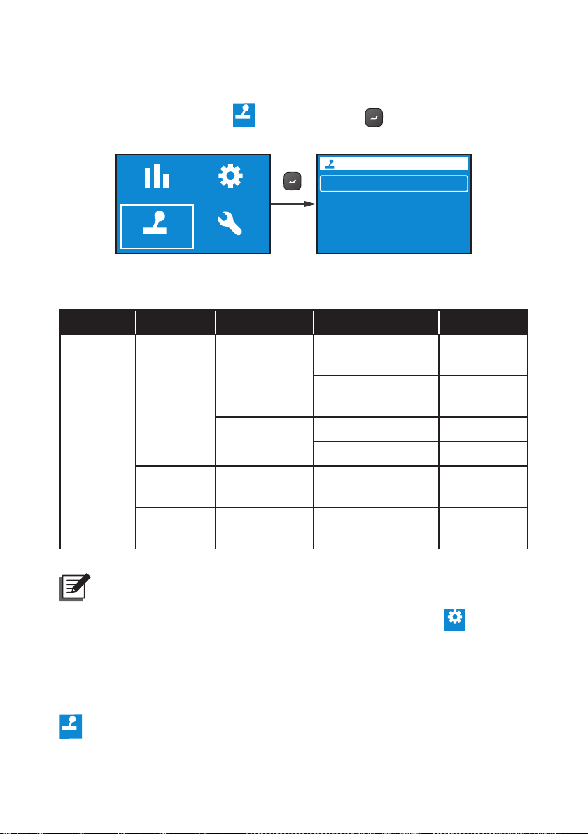
9.2.3 Control Menu
Control
Setting
Control
In Main Menu, after selecting
, press the button
to enter into the Control
Menu.
Measurement
Control
Setting
Maintenance
Output
Charger
Alarm
The Control Menu provides commands for enabling specic UPS functions. Please
refer to the table below for the setup items and selectable values.
LEVEL 1 LEVEL 2 LEVEL 3 LEVEL 4 LEVEL 5
Output Reboot
Immediately
Yes/ No
Outlet Group 1
Control
Output
Bypass*
Output Reboot
With Delay
1
Go into Bypass Yes/ No
Yes/ No
Go out of Bypass Yes/ No
Charger
Alarm
Execute Boost
Charge
Clear Prediction
Warning*
2
Yes/ No
Yes/ No
For example, if you need the UPS to reboot the output immediately, please go to
Amplon RT Series
NOTE :
1. *1: The item Bypass will be hidden if you set the Standby Mode as
Bypass Output. To set up Bypass Output, please go to
→ Output
→ Standby Mode → Bypass Output.
2
: The item Delay Alarm Again under Control → Alarm → Clear
2. *
Prediction Warning can be set from 1 week to 52 weeks.
→ Output → Outlet Group 1 → Output Reboot Immediately → Yes.
54
Page 59

- Output
Maintenance
Outlet Group 1
Bypass
- Output - Main
Output Reboot Immediately
Output Reboot With Delay
Chapter 9 LCD Display & Settings
Output Reboot
immediately
UPS will reboot immediately
Cancel
Yes
9.2.4 Maintenance Menu
In Main Menu, after selecting
Maintenance Menu.
Measurement
Control
Maintenance
, press the button
Setting
Output Reboot
immediately
UPS will reboot immediately
Cancel
Yes
Reboot
to enter into the
Test
Battery Aging
Reset
Log
About
1 /2
2 /2
55
Page 60

The Maintenance Menu provides commands for enabling UPS maintenance
functions. It also provides event logs and UPS identification. Please refer to the
table below for the setup items and selectable values.
LEVEL 1 LEVEL 2 LEVEL 3 LEVEL 4 LEVEL 5
Test Result: Pass
Maintenance
Test
Battery
Aging
Start Battery Test
Deep Discharge Test
Local Output Dry
Contact Test
Create Discharging
Reference
Battery Discharging
History
Test in
Progress…
Test in
Progress…
Dry Contact 1
Dry Contact 2
Dry Contact 3
Dry Contact 4
Yes/ Cancel
Item, Output
power, Total
discharging time
Test Result: Fail
Test Result: Not
Finished
Test Result: Pass
Test Result: Fail
Test Result: Not
Finished
Dry Contact 1
In Progress…
Dry Contact 2
In Progress…
Dry Contact 3
In Progress…
Dry Contact 4
In Progress…
Date/ Time,
Average load(W),
Actual discharging
time,
Estimated remaining
time,
Total discharging time
Amplon RT Series
Reset
Reset Power Usage
Calculator
Restore Factory
Setting
56
Yes/ Cancel
Yes/ Cancel
Page 61

Chapter 9 LCD Display & Settings
LEVEL 1 LEVEL 2 LEVEL 3 LEVEL 4 LEVEL 5
Description,
Event code
YYYY/MM/DD
HH:MM:SS
Error Description
Maintenance
Log
About
Event List
Clear Log Yes/Cancel
Model Name: RT-5K
UPS - Part No.
UPS502R2RT0B035
UPS - Serial No.
1BA0150001
UPS - Manufacture
Date
YYYY-MM
PS Firmware –
Version
06AR004
Battery Summary:
Installed YYYY/MM/
DD
Replace YYYY/MM/
DD
57
Page 62

For example, if you need to execute a battery test, please go to Test → Start
Battery Test → Test In Progress… → Test Result: Pass (or Fail).
Test
Battery Aging
Reset
Log
1 /2
- Test
Start Battery Test
Deep Discharge Test
Local Dry Contact test
Battery Test
Test In Progress...
Battery
Press ESC key to abort test
Battery Test
272.0V
85%
Test In Progress...
Battery
Press ESC key to abort test
272.0V
85%
ESC
ESC
Amplon RT Series
Battery Test
Test In Progress...
Battery
Press ESC key to abort test
272.0V
Test Completed
58
ESC
85%
Page 63

Chapter 9 LCD Display & Settings
A. B.
Once the test is completed, the test result will be shown as follows.
A. Test Result_ Fail: The alarm icon will show in the left bottom of the LCD display.
B. Tests Result_ Pass: No alarm icon occurs, and the UPS runs normally.
Alarm
Icon
Battery Test
Battery Test
Test In Progress...
Test Result: FAIL
Battery
Battery
72.0V 85%
272.0V
0%
Press ESC key to Escape
ONLINE
0X1012 01
!
X
1
75%
Battery disconnect or need replaced.
Battery Test
Battery Test
Test In Progress...
Test Result: Pass
Battery
Battery
72.0V 85%
272.0V
Press ESC key to Escape
ONLINE
%
100
Input
Output
232.0V
232.0V
50.0Hz
50.0Hz
80%
1
75
%
59
Page 64

Chapter 10 : Optional Accessories
There are several optional accessories available for this RT series UPS. Please
refer to the table below for the optional accessories and their functions.
No. Item Function
1 Dust Filter(s)
2 Mini SNMP IPv6 Card
3 Mini Relay I/O Card Increases the quantity of dry contacts.
4 Mini MODBUS Card
External Battery Pack
Cable Extension Kit
5
(includes 2 annular
terminals and 2 butt
joint connectors)
Delta External Battery
6
Pack
7 Rail Kit Fixes the UPS in a rack cabinet rmly.
Prevent(s) dust from entering into the UPS to
ensure UPS reliability and to prolong product life.
Monitors and controls the status of the UPS via a
network system.
Lets the UPS have MODBUS communication
function.
Use the external battery pack cable extension kit
to extend its range.
Provides external batteries to let the UPS continue
supplying power to its connected loads when a
power outage occurs.
NOTE :
1. For detailed installation and operation of any accessory mentioned
above, please refer to the Quick Guide, User Guide, or Installation
& Operation Guide included in the package of the relevant optional
accessory.
2. If you want to buy any accessory mentioned above, please contact your
local dealer or customer service.
Amplon RT Series
60
Page 65

Chapter 11 Troubleshooting
Chapter 11 : Troubleshooting
1. When a problem occurs, please check if following situations exist before
contacting Delta service personnel:
z
z
Is the main input voltage present?
2. Please have the following information ready if you would like to contact the Delta
service personnel:
z
z
Unit information including model, serial number, etc.
z
z
An exact description of the problem. The more detailed description of the
problem, the better.
3. When you see the following problems occur, please refer to the solutions shown
below.
Error
Code
Alarm
Message
0x61C1 Input Fuse Open
0X60C0 PFC Soft Start Fail
0X6200
0X62A0
0X62C0
DC Bus Over
Shutdown
DC Bus Under
Shutdown
DC Bus Under
Shutdown
0x1200 INV Volt Abnormal
Possible
Cause
The input fuse is
melted or the input
relay is open.
The UPS has an
internal fault.
1. The output has
capacitive or
inductive loads.
2. The UPS has an
internal fault.
The UPS has an
internal fault.
The UPS has an
internal fault.
The UPS has an
internal fault.
Solution
Please contact
service personnel.
Please contact
service personnel.
1. Remove the
capacitive or
inductive loads.
2. Please contact
service personnel.
Please contact
service personnel.
Please contact
service personnel.
Please contact
service personnel.
61
Page 66

Error
Code
0x1101
Alarm
Message
Output Overload
Shutdown
Possible
Cause
The UPS is overloaded.
Solution
Check the power
consumption of the
loads, and remove
the unnecessary
loads.
0xA000 Charger Fault
0x8106
0X6100
0x1003
INV IGBT Over
Heat Shutdown
PFC Over Heat
Shutdown
Battery
Disconnected
The UPS has an
internal fault.
1. The vents are
blocked.
2. The UPS has an
internal fault.
1. The vents are
blocked.
2. The UPS has an
internal fault.
1. The UPS is
not properly
connected to the
external battery
pack(s).
2. The battery/
batteries is (are)
damaged.
Please contact
service personnel.
1. Check whether the
vents are blocked.
2 Contact service
personnel.
1. Check whether the
vents are blocked.
2. Contact service
personnel.
1. Check whether the
UPS is properly
connected to the
external battery
pack(s).
2. Contact service
personnel.
NOTE :
If all possible causes are eliminated but the alarm still appears, please
contact your local dealer or customer service.
Amplon RT Series
62
Page 67

Chapter 12 Maintenance
100
%
Chapter 12 : Maintenance
12.1 UPS
z
z
UPS Cleaning
Regularly clean the UPS, especially the slits and openings, to ensure that the
air freely ows into the UPS to avoid overheating. If necessary, use an air-gun
to clean the slits and openings to prevent any object from blocking or covering
these areas.
z
z
UPS Regular Inspection
Regularly check the UPS every half year and inspect:
1. Whether the UPS, LEDs, and alarm function are operating normally.
2. Whether battery voltage is normal. If battery voltage is too high or too low,
nd the root cause.
12.2 Batteries
The RT series UPS uses sealed lead-acid batteries. Though the typical battery
life cycle is 3~5 years, the battery life depends on the temperature, usage, and
charging/ discharging frequency. High temperature environments and high charging/
discharging frequency will quickly shorten the battery life. The UPS does not require
user maintenance; however, the batteries should be checked periodically. Please
follow the suggestions below to ensure a normal battery lifetime.
z
z
Keep the usage temperature at 20°C ~ 25°C.
z
z
Idle batteries must be fully recharged every three months if the UPS needs to be
stored for an extended period of time. Please fully charge the batteries (internal
and external) until the battery capacity percentage shown on the UPS’s LCD is
100%
.
(
)
NOTE :
If the UPS’s internal batteries need to be replaced, please contact
qualified service personnel. During battery replacement, the loads
connected to the UPS will not be protected if input power fails.
63
Page 68

12.3 Fans
Higher temperatures shorten fan life. When the UPS is running, please periodically
check if each fan works normally and make sure if the ventilation air can move freely
around and through the UPS. If not, contact service personnel to replace the fans.
NOTE :
Please ask your local dealer or customer service for more maintenance
information. Do not perform maintenance if you are not trained for it.
Amplon RT Series
64
Page 69

Appendix 1 Technical Specications
Appendix 1 : Technical Specications
Model RT-5K RT-6K RT-8K RT-10K
Power Rating
5kVA/5kW
5kVA/4.5kW*
6kVA/6kW 8kVA/8kW 10kVA/10kW
1
Waveform Pure Sinewave
Nominal
Voltage
Voltage
Range
1
200*
/208*1/220/230/240 Vac
175 ~ 280Vac (100% load);
100 ~ 174Vac (50% ~ 100% load)
Frequency 50/60 Hz ± 10 Hz
Input
Power Factor 0.99 (full load)
iTHD < 3% (linear load)
B8
NEMA L6-30P
power cord
(10 ft)
Sux:
Con-
nection
Sux:
35
Power Factor Unity*
Voltage 200*1/208*1/220/230/240 Vac
Voltage
Regulation
± 1% (linear load)
Terminal
Terminal
1
Output
Frequency 50/60 Hz ± 0.05 Hz
vTHD <2% (linear load) <3% (linear load)
Overload
Capacity
Cress
Factor
< 105%: continuous; 105% ~ 125%: 2 minutes;
125% ~ 150%: 30 seconds; >150%, 500 ms
3:1
65
Page 70

Model RT-5K RT-6K RT-8K RT-10K
Output
Eciency
Battery &
Charger
NEMA L6-30 × 1 (load bank)
Sux:
B8
Con-
nection
Sux:
35
Online Mode Up to 95.5%
ECO Mode Up to 99%
Battery Voltage 192 Vdc 240 Vdc
Battery Type
Backup Time
(100% load/
75% load)
Charging
Current
Recharge
Time
5K: NEMA L6-20 x 2,
L6-30 x 1
6K: NEMA L6-20 × 2,
L6-30 × 1, Terminal × 1
IEC C19 × 1 (load bank)
Terminal × 1,
C13 × 6, C19 × 2
12V/7Ah Sealed
lead-acid battery
5.5/8.5 minutes
(O/P PF 0.9)
5/7.5 minutes
(O/P PF unity)
1A (default) 1.5A (default)
minutes
3/5.5
< 3 hours to 90%
NEMA L6-30 × 1 (load bank)
Terminal × 1,
L6-20 × 2,
L6-30 × 2
IEC C19 × 1 (load bank)
Terminal × 1,
C13 × 6, C19 × 4
12V/9Ah Sealed
lead-acid battery
5/9
minutes
3.5/6
minutes
Audible Noise 48 dBA 50 dBA
Display LED indicators and LCD display
Communication
Interfaces
Dimensions
(W × D × H)
Physical
Weight
Amplon RT Series
Sux:
B8
Sux:
35
MINI Slot × 1, RS-232 Port × 1, USB Port × 1,
REPO/ROO × 1, RS-485 Port × 1, Dry Contact × 4
440 × 665 × 176 mm
17.3 × 26.2 × 6.9 inch
55 kg
(121.23 lb)
54 kg
(119.1 lb)
(121.23 lb)
(119.1 lb)
66
55 kg
54 kg
440 × 750 × 218 mm
17.3 × 29.5 × 8.6 inch
86 kg
(189.6 lb)
85.5 kg
(188.5 lb)
(189.6 lb)
(188.5 lb)
86 kg
85.5 kg
Page 71

Appendix 1 Technical Specications
Model RT-5K RT-6K RT-8K RT-10K
Environ-
ment
Operating
Altitude
Operating
Temperature
Storage
Temperature
Relative
Humidity
0 ~ 1000 m (0 ~ 3300 ft) (without derating)
0 ~ 3000 m (0 ~ 10000 ft);
0°C ~ 40°C (32 ~ 104°F)
-15°C ~ 50°C (-59 ~122°F)
5% ~ 95% (non-condensing)
NOTE :
1. *1: For the sux B8 model, the output power factor for 5kVA UPS is 0.9.
However, when the output voltage is at 200V, the 5kVA UPS needs to be
de-rated to 90% of its capacity.
2. Please refer to the rating label for the safety rating.
3. All specications are subject to change without prior notice.
67
Page 72

Appendix 2 : Warranty
Seller warrants this product, if used in accordance with all applicable instructions,
to be free from original defects in material and workmanship within the warranty
period. If the product has any failure problem within the warranty period, Seller will
repair or replace the product at its sole discretion according to the failure situation.
This warranty does not apply to normal wear or to damage resulting from improper
installation, operation, usage, maintenance or irresistible force (i.e. war, fire,
natural disaster, etc.), and this warranty also expressly excludes all incidental and
consequential damages.
Maintenance service for a fee is provided for any damage out of the warranty
period. If any maintenance is required, please directly contact the supplier or Seller.
WARNING:
The individual user should take care to determine prior to use whether the
environment and the load characteristic are suitable, adequate or safe for
the installation and the usage of this product. The User Manual must be
carefully followed. Seller makes no representation or warranty as to the
suitability or tness of this product for any specic application.
Amplon RT Series
No. 501326760102
Version : V 1.2
Release Date : 2019_03_08
68
Page 73

Page 74

5013267601
 Loading...