

Page 1
TP-0143620-01
*We reserve the right to change the information in this manual without prior notice.
2014-10-31
TP70P
www.deltaww.com
Quick Start
Page 2

TP70P Quick Start
Table of Contents
Chapter 1 Introduction
1.1 Introduction of TP70P.................................................................1-2
1.2 Related Manuals ........................................................................1-2
1.3 Profile and Dimensions ...............................................................1-3
1.3.1 Profile ................................................................................1-3
1.3.2 Dimensions of TP70P............................................................ 1-4
1.3.3 Dimensions of an Opening.....................................................1-5
1.4 Definitions of External Connectors................................................1-5
1.5 Functional Specifications............................................................. 1-6
1.5.1 Arrangement of I/O Terminals................................................1-6
1.5.2 Devices in a PLC ..................................................................1-7
1.6 Electrical Specifications...............................................................1-8
1.6.1 Specifications for PLCs..........................................................1-8
1.6.2 Electrical Specifications for Digital Input Terminals....................1-9
1.6.3 Electrical Specifications for Digital Output Terminals..................1-9
1.6.4 Electrical Specifications for Analog I/O Terminals....................1-10
1.7 Installation .............................................................................1-11
1.8 Wiring....................................................................................1-12
1.8.1 Wiring a Power Input Connector...........................................1-12
1.8.2 Wiring Input Terminals........................................................1-13
1.8.3 Wiring Relay Output Terminals.............................................1-13
1.8.4 Wiring Analog Input Channels..............................................1-14
1.8.5 Wiring Analog Output Channels............................................1-15
1.8.6 Wiring Temperature Measurement Input Terminals..................1-16
1.9 Definitions of the Pins in Communication Ports.............................1-16
1.10 Controllers Supporting TP70P ....................................................1-17
Chapter 2 Writing Programs
2.1 Preparations..............................................................................2-2
2.1.1 Hardware............................................................................2-2
2.1.2 Software.............................................................................2-2
2.1.3 Tools and Materials...............................................................2-2
2.2 Wiring......................................................................................2-2
2.2.1 Wiring Diagram for a Delta VFD-M Series AC Motor Drive...........2-3
i
Page 3

2.2.2 Wiring Diagram for External Terminals....................................2-3
2.2.3 Wiring Diagram for Communication........................................2-3
2.2.4 Setting Parameteres in a Delta VFD-M Series AC Motor Drive..... 2-4
2.3 Example................................................................................... 2-4
2.4 Writing a Program for a Text Panel............................................... 2-5
2.4.1 Planning Objects ................................................................. 2-7
2.4.2 Managing Pages ..................................................................2-7
2.4.3 Creating Objects.................................................................. 2-8
2.4.4 Basic Configuration............................................................ 2-15
2.4.5 Compile and Downloading a Program.................................... 2-16
2.5 Writing a Program for a PLC...................................................... 2-18
2.5.1 Planning a Program............................................................ 2-20
2.5.2 Control Program................................................................ 2-21
2.5.3 Compiling and Downloading a Program................................. 2-22
2.6 Monitoring and Debugging a Program......................................... 2-23
2.6.1 Monitoring a Program......................................................... 2-23
2.6.2 Removing System Errors .................................................... 2-27
Chapter 3 Frequently Asked Questions and Answers
3.1 Installing a USB Driver............................................................... 3-2
3.2 Descriptions of the Communication Ports on TP70P......................... 3-4
3.3 Setting COM2............................................................................ 3-5
3.4 Using COM2 as a Master Station .................................................. 3-6
3.5 Setting COM3............................................................................ 3-7
3.6 Setting an RTU Mode for COM3.................................................... 3-9
3.7 Using COM3 as a Slave Station.................................................. 3-10
3.8 Data Exchange........................................................................ 3-12
ii
Page 4

Chapter 1 Introduction
Table of Contents
1.1 Introduction of TP70P.................................................................1-2
1.2 Related Manuals ........................................................................1-2
1.3 Profile and Dimensions ...............................................................1-3
1.3.1 Profile ................................................................................1-3
1.3.2 Dimensions of TP70P............................................................ 1-4
1.3.3 Dimensions of an Opening.....................................................1-5
1.4 Definitions of External Connectors................................................1-5
1.5 Functional Specifications............................................................. 1-6
1.5.1 Arrangement of I/O Terminals................................................1-6
1.5.2 Devices in a PLC ..................................................................1-7
1.6 Electrical Specifications...............................................................1-8
1.6.1 Specifications for PLCs..........................................................1-8
1.6.2 Electrical Specifications for Digital Input Terminals....................1-9
1.6.3 Electrical Specifications for Digital Output Terminals..................1-9
1.6.4 Electrical Specifications for Analog I/O Terminals ....................1-10
1.7 Installation .............................................................................1-11
1.8 Wiring....................................................................................1-12
1.8.1 Wiring a Power Input Connector...........................................1-12
1.8.2 Wiring Input Terminals........................................................1-13
1.8.3 Wiring Relay Output Terminals.............................................1-13
1.8.4 Wiring Analog Input Channels..............................................1-14
1.8.5 Wiring Analog Output Channels............................................1-15
1.8.6 Wiring Temperature Measurement Input Terminals..................1-16
1.9 Definitions of the Pins in Communication Ports.............................1-16
1.10 Controllers Supporting TP70P .................................................1-17
1-1
Page 5

TP70P Quick Start
1.1 Introduction of TP70P
TP70P is highly flexible in that it can be connected to various devices. The devices which can be connected to
TP70P are shown in the block diagram below.
TPEditor
WPLSoft
ISPSof t
USB port
Serial
COM port
Othe r OCS devic es
Dri ves
PLCs
TP70P
Barcode readers
Sensors
Ind ica to rs
Alar ms
Encoders
Pumps
External I/O
Pr i nt ers
SCADA
OPC servers
Seri al I/O
Relays
Solenoids
The functions of TP70P are described below.
The LCD on TP70P can display 65535, and is a touchscreen.
TP70P provides various kinds of objects, including X-Y curves, circular meters, bars, sliders, and alarms.
TP70P supports PLC Links.
The driver in TP70P supports Delta controllers. It can be connected to Delta servers, inverters, and
temperature controllers.
There are two serial communication ports. One supports PLC communication, and the other supports
TP70P communication.
The USB port on TP70P can communicate with a computer. It supports the use of
WPLsoft/ISPsoft/TPEditor to upload/download a program and to monitor devices.
There are four models which have different I/O configurations. They can be connected to various types of
output devices.
1.2 Related Manuals
The manuals related to TP70P are described below.
TP70P Instruction Sheet: TP70P Instruction Sheet provides information related to TP70P for users who
use TP70P for the first time. (TP70P Instruction Sheet is attached to a TP70P series text panel.)
DVP-ES2/EX2/SS2/SA2/SX2/SE&TP Operation Manual: DVP-ES2/EX2/SS2/SA2/SX2/SE&TP Operation
Manual Introduces the PLC instructions supported by TP70P. Users can find the manual on the Delta
website.
TPEditor User Manual: TPEditor User Manual introduces the usage of TPEditor, including the interface of
TPEditor, and the objects which can be displayed on a text panel. Users can find the manual on the Delta
website or in TPEditor.
WPLSoft User Manual: WPLSoft User Manual introduces the usage of WPLSoft, including the interface of
WPLSoft, and the objects which can be used. Users can find the manual in WPLSoft.
ISPSoft User Manual: ISPSoft User Manual introduces the usage of ISPSoft, including variables,
connections, programs, and function blocks. Users can find the manual on the Delta website or in ISPSoft.
TP70P Quick Start: TP70P Quick Start introduces the functions of TP70P, the wiring of TP70P, the
installation of TP70P, the system of TP70P, and the usage of TP70P.
1-2
Page 6
1.3 Profile and Dimensions
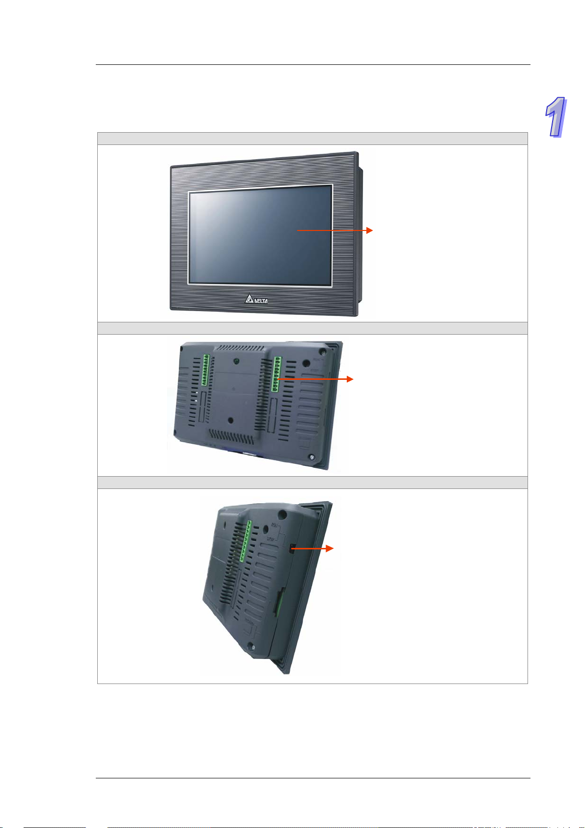
1.3.1 Profile
Front view
Back view
Chapter 1 Introduction
Display/Touchscreen
Side view
Input/Output connector
RUN/STOP switch
1-3
Page 7
TP70P Quick Start
Side view
1.3.2 Dimensions of TP70P
Front side and right side (Unit: mm)
TP70P-16TP1R, TP70P-32TP1R, TP70P-22XA1R, TP70P-21EX1R
205.6
USB p ort
Communication port
DC power input connector
TP70P-RM0
49.0
142.6
205.6
142.6
1-4
37.0
Page 8

Chapter 1 Introduction
1.3.3 Dimensions of an Opening
If protection against water is required (NEMA 4X), a hole should be made to a tolerance of ±0.1 mm.
127.1
~
128.0
Thickness
190.1~191. 0
Unit: mm
0.5~4
1.4 Definitions of External Connectors
TP70P-16TP1R
1
○
○
S/S C0
X0 Y0
X1 Y1
X2 Y2
X3 Y3
X4 Y4
X5 Y5
X6 Y6
X7 Y7
. .
2
1
3
TP70P-32TP1R
1
○
○2 ○3 ○
S/S0 C0 S/S0 C1
X0 Y0 X10 Y10
X1 Y1 X11 Y11
X2 Y2 X12 Y12
X3 Y3 X13 Y13
X4 Y4 X14 Y14
X5 Y5 X15 Y15
X6 Y6 X16 Y16
X7 Y7 X17 Y17
. . . .
4
2
4
TP70P-22XA1R
1
2
○
○
S/S0 C0 V0+ V3+
X0 Y0 VI0- VI3X1 Y1 I0+ I3+
X2 Y2 V1+ FE
X3 Y3 VI1- VO4
X4 Y4 I1+ IO4
X5 Y5 V2+ AG
X6 Y6 VI2- VO5
X7 Y7 I2+ IO5
. . FE AG
○3○
4
TP70P-21EX1R
1
○
○2 ○
S/S0 C0 I0+ L3+
X0 Y0 I0- L3X1 Y1 FE I3X2 Y2 I1+ FE
X3 Y3 I1- .
X4 Y4 FE L4+
X5 Y5 . L4X6 Y6 IO2 I4X7 Y7 AG FE
. . FE .
3
4
○
1-5
Page 9
TP70P Quick Start
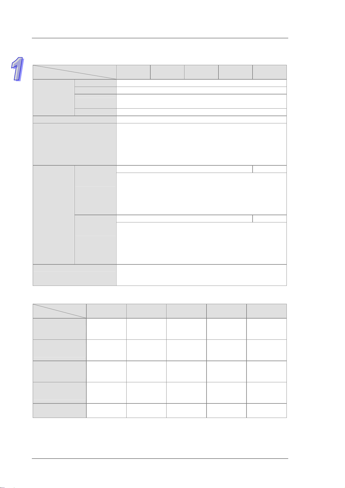
1.5 Functional Specifications
Model
Specifications
Screen/Color 7” TFT LCD (65535 colors)
Resolution 800×480 pixels
Display
Driver Delta product
USB port
Extension
communication
ports
Monitoring devices
Backlight type
Display area Width × Height = 154 × 85 (Unit: mm); 7 inches (diagonal)
COM2
COM3
TP70P
-32TP1R
LED backlight (It has a lifespan of twenty thousand hours at a
temperature of 25℃)
Transmission: Virtual communication port
Data length: 7 bits or 8 bits
Stop bit: 1 bit or 2 bits
Parity check: None/Odd/Even
Transmission rate: 9,600 bps~115,200 bps
USB port: Type B USB connector
RS-485 RS-232
Data length: 7 bits or 8 bits
Stop bit: 1 bit or 2 bits
Parity check: None/Odd/Even
Transmission rate: 9,600 bps~115,200 bps
Connector: Male DB-9 connector (Please refer to section 1.9 for more
information.)
RS-485/RS-422 RS-485
Data length: 7 bits or 8 bits
Stop bit: 1 bit or 2 bits
Parity check: None/Odd/Even
Transmission rate: 9,600 bps~115,200 bps
Connector: Male DB-9 connector (Please refer to section 1.9 for more
information.)
After a program is downloaded to a text panel by means of the virtual
communication port on the text panel, the devices in the PLC connected
to the text panel can be monitored.
TP70P
-16TP1R
TP70P
-22XA1R
TP70P
-21EX1R
TP70P
-RM0
1.5.1 Arrangement of I/O Terminals
Model
Specifications
Digital input terminal
Digital output
terminal
Analog input
terminal
Analog output
terminal
Temperature input
terminal (Pt100)
TP70P
-32TP1R
X0~X7,
X10~X17
(16 terminals)
Y0~Y7,
Y10~Y17
(16 terminals)
-- --
-- --
-- -- --
TP70P
-16TP1R
X0~X7
(8 terminals)
Y0~Y7
(8 terminals)
TP70P
-22XA1R
X0~X7
(8 terminals)
Y0~Y7
(8 terminals)
Voltage/Current
4 channels
(12-bit)
Voltage/Current
2 channels
(12-bit)
TP70P
-21EX1R
X0~X7
(8 terminals)
Y0~Y7
(8 terminals)
Current
2 channels
(12-bit)
Current
1 channel
(12-bit)
2 channels
(16-bit)
TP70P
-RM0
--
--
--
--
--
1-6
Page 10
1.5.2 Devices in a PLC
Item Range
X External input relay X0~X7; X10~X17
Y External output relay Y0~Y7; Y10~Y17
Auxiliary relay
General
M
Relay Bit device
T
Relay Bit device
C
S
T Present value in a timer T0~T255: 256 timers
Register Word device
C Present value in a counter
D
Latching
Special
100 ms (If M1028 is On,
T64~T126 will be 10
millisecond timers.)
Timer
10 ms (If M1038 is On,
T200~T245 will be 1
millisecond timers.)
1 ms
16-bit up counter
Counter
32-bit up/down counter
32-bit high-speed
up/down counter
Stepping relay
Initialization S0~S9: 10 stepping relays (*2)
Returning to zero
Latching S20~S127: 108 stepping relays (*2)
General S128~S911: 784 stepping relays (*1)
Alarm S912~S1023: 112 stepping relays (*2)
General
Data register
Retentive
Special
Index E0~E7, F0~F7: 16 data registers (*1)
M0~M511: 512 auxiliary relays (*1)
M768~M999: 232 auxiliary relays (*1)
M2000~M2047: 48 auxiliary relays (*1)
M512~M767: 256 auxiliary relays (*2)
M2048~M4095: 2048 auxiliary relays (*2)
M1000~M1999: 1000 auxiliary relays
Some of them are latching auxiliary relays
T0~T126: 127 timers (*1)
T128~T183: 56 timers (*1)
T184~T199 (for subroutines): 16 timers (*1)
T250~T255 (accumulation): 6 timers (*1)
T200~T239: 40 timers (*1)
T240~T245 (accumulation), 6 timers (*1)
T127: 1 timer (*1)
T246~T249 (accumulation): 4 timers (*1)
C0~C111: 112 counters (*1)
C128~C199: 72 counters (*1)
C112~C127: 16 counters (*2)
C200~C223: 24 counters (*1)
C224~C232: 9 counters (*2)
C233~C234: 2 counters (*2)
C237~C250: 14 counters (*2)
C252~C255: 3 counters (*2)
C235, C236: 2 one-phase one-input counters (*2)
C251: 1 two-phase two-input counter (*2)
S10~S19: 10 stepping relays (S10~S19 and the
instruction IST are used together.) (*2)
C0~C199: 200 16-bit counters
C200~C254: 55 32-bit counters
D0~D407: 408 data registers (*1)
D600~D999: 400 data registers (*1)
D3920~D3999: 80 data registers (*1)
D408~D599: 192 data registers (*2)
D2000~D3919: 1920 data registers (*2)
D1000~D1999: 1000 data registers (Some of them
are retentive data registers.)
D4000~D4999: 1000 data registers (*2)
Chapter 1 Introduction
(*4)
4096
auxiliary
relays in
total
256
timers in
total
140
counters
in total
3
counters
in total
1024
stepping
relays in
total
5000 data
registers
in total
1-7
Page 11
TP70P Quick Start
Item Range
N Master control loop N0~N7: 8 N devices
P Pointer P0~P255: 256 pointers
Pointer
I
Constant
K Decimal system
H Hexadecimal system
Note:
*1: They are not latching/retentive devices. They can not be changed.
*2: They are latching/retentive devices. They can not be changed.
*3: Please refer to section 1.9 for more information.
*4: Please refer to section 1.5.1 for more information.
External interrupt
Interrupt
Timer interrupt I602~I699, I702~I799: 2 interrupts (Time base=1 ms)
High-speed interrupt I010: 1 interrupt
Communication
interrupt
I000/I001(X0), I100/I101(X1)
(01: Rising edge-triggered
I150 (COM2): 1 interrupt (*3)
K-32,768~K32,767 (16-bit operation)
K-2,147,483,648~K2,147,483,647 (32-bit operation)
H0000~HFFFF (16-bit operation)
H00000000~HFFFFFFFF (32-bit operation)
1.6 Electrical Specifications
; 00: Falling edge-triggered )
1.6.1 Specifications for PLCs
Model
Item
CPU 32-bit ARM Cortex-M4 MCU
Program
memory
Internal
memory
Retentive
memory
Supply
voltage
Electric
energy
consumption
Power
protection
Insulation
impedance
Noise
immunity
Ground
Battery 3 V CR2032 battery
Battery
lifespan
Operating
temperature
TP70P
-16TP1R
Flash ROM: 128 MB
(OS: 30 MB/Backup: 16 MB/User AP: 82 MB)
64 Mbytes
32 Kbytes
24 V DC (-15%~20%) (DC input power polarity reversal protection)
5W 5W 5W 5W 3W
DC input power polarity reversal protection
> 5 MΩ (The voltage between all I/O terminals and the ground is 500 V DC.)
ESD (IEC 61131-2, IEC 61000-4-2): 8 kV Air Discharge
EFT (IEC 61131-2, IEC 61000-4-4): Power Line: 2 kV, Digital I/O: 1 kV, Analog &
Communication I/O: 1 kV
Damped-Oscillatory Wave: Power Line: 1 kV, Digital I/O: 1 kV
RS (IEC 61131-2, IEC 61000-4-3): 26 MHz~1 GHz, 10 V/m
The diameter of the ground used should not be less than the diameters of the wires
connected to the power terminals of the PLC used.
(If several PLCs are used simultaneously, please use single-point ground.)
3 years at a temperature of 25℃
0°C~50°C
Relative humidity: 20% - 90% RH【0~40℃】,10%~55% RH【41~50℃】
Pollution degree 2 (No condensation)
TP70P
-32TP1R
TP70P
-22XA1R
TP70P
-21EX1R
TP70P
-RM0
1-8
Page 12
Chapter 1 Introduction
Model
Item
Storage
temperature
Vibration/Sho
ck resistance
Dimensions 175.8 × 108.6 × 59.2 mm (Width × Height × Depth)
Cooling Transfer of thermal energy via convection
TP70P
-16TP1R
-20°C~60°C
International standards IEC61131-2, IEC 68-2-6 (TEST Fc)/IEC61131-2 & IEC 68-2-27 (TEST
Ea)
TP70P
-32TP1R
TP70P
-22XA1R
TP70P
-21EX1R
1.6.2 Electrical Specifications for Digital Input Terminals
Electrical specifications for digital input terminals
Model
Item
Input terminal X0, X1 X2~X7, X10~X17
Input form
Input voltage (±10%) 24 V DC, 5 mA
Input impedance 4.7 kilohm
Maximum input
frequency
Action levle
time
OffOn > 16.5 V DC
OnOff < 8 V DC
OffOn <20 us Response
OnOff <50 us
24 V DC (-15% ~ 20%) single common terminal
Sinking current: Current flows into the terminal S/S.
Sourcing current: Current flows from the terminal S/S.
10 kHz 60 Hz
10 ms
TP70P
-RM0
1.6.3 Electrical Specifications for Digital Output Terminals
Model
Item
Output type Relay
Voltage 250 V AC, < 30 V DC
Resistance 1.5 A/point (5 A/COM)
Current
time
Maximum output
frequency
#1: Life curves
3,000
2,000
1,000
)
3
0
1
X
(
n
o
i
t
a
r
e
p
O
Inductance #1
Bulb 20 W DC/100 W AC
OffOn Response
OnOff
50 0
30 0
20 0
10 0
50
30
20
0.1
0.2
Electrical specifications for digital output terminals
Approximately 10 ms
50 Hz
120VAC Resi stive
30 VD C Inducti ve( t= 7m s)
240VAC Inductive(cos 0.4)
120VAC Inductive(cos =0.4)
30 VDC
Inductive
(t=40ms)
ψ
=
ψ
Contact
0.5
0.3 0. 7
12
Current(A)
1-9
Page 13
TP70P Quick Start
1.6.4 Electrical Specifications for Analog I/O Terminals
Electrical specifications for the analog I/O terminals on TP70P-22XA1R
Electrical specifications for the analog I/O terminals on TP70P-22XA1R Model
Item
Analog input range ±10 V ±20 mA -- --
Analog output range -- -- ±10 V 0~20 mA
Digital conversion
range
Resolution
Input impedance Above 200 kΩ 250 Ω -- --
Output impedance -- -- 100 Ω
Overall accuracy
Response time 3 ms/channel
Isolation No isolation
Absolute input range ±15 V ±32 mA -- --
Digital data type
Maximum output
current
(Allowable load)
Protection --
Electrical specifications for the analog I/O terminals on TP70P-21EX1R
Item
Sensor type -- -- 2-wire/3-wire Pt100
Driving current -- -- 1.6 mA
Analog input range 0~20 mA -- -20 ~160℃℃
Analog output range -- 0~20 mA -Digital conversion
range
Resolution 11 bits (1 lsb=10 uA) 12 bits (1 lsb=10 uA) 12 bits (0.1 )℃
Input impedance 250 Ω --
Output impedance -- 100 Ω
Overall accuracy
Response time 3 ms/channel 300 ms × Quantity of channels
Isolation No isolation
Absolute input range 0~32 mA -- --
Digital data type
Voltage input Current input Voltag e output Current output
±2000 ±1000 ±2000 0~4000
12 bits
(1 lsb=5 mV)
If a signal reaches full scale at a temperature of 25 (77 ), there will ℃℉ be an error in
the range of ±0.5%
If a signal reaches full scale at a temperature in the range of 0~55 (32~131 ), ℃℉
there will be an error in the range of ±1%.
16-bit two’s complement
There are 11 significant bits.
--
Electrical specifications for the analog I/O terminals on TP70P-21EX1R Model
Current input Current output Temperature measurement
0~2000 0~2000 -200~1600
If a signal reaches full scale at a temperature of
25 (77 ), there will ℃℉ be an error in the ran ge of
±0.5%.
If a signal reaches full scale at a temperature in the
range of 0~55 (32~131 ), there will be an error ℃℉
in the range of ±1%.
16-bit two’s complement
There are 11 significant bits.
11 bits
(1 lsb=20 uA)
12 bits
(1 lsb=2.5 mV)
10 mA
(1 kΩ~2 MΩ)
The voltage output terminals are
equipped with short circuit protection.
(Please do not short-circuit the voltage
output terminals for a long time, otherwise
they may be burned.) The current output
terminals can have open circuits.
If a signal reaches full scale at a
temperature in the range of
0~55 (32~131 ), there will be ℃℉
an error in the range of ±1%.
12 bits
1 lsb=5 uA
0~500 Ω
1-10
Page 14
Chapter 1 Introduction
Electrical specifications for the analog I/O terminals on TP70P-21EX1R Model
Item
Maximum output
current
(Allowable load)
Protection --
Current input Current output Temperature measuremen t
-- 0~500 Ω --
The current output
terminals can have
open circuits.
--
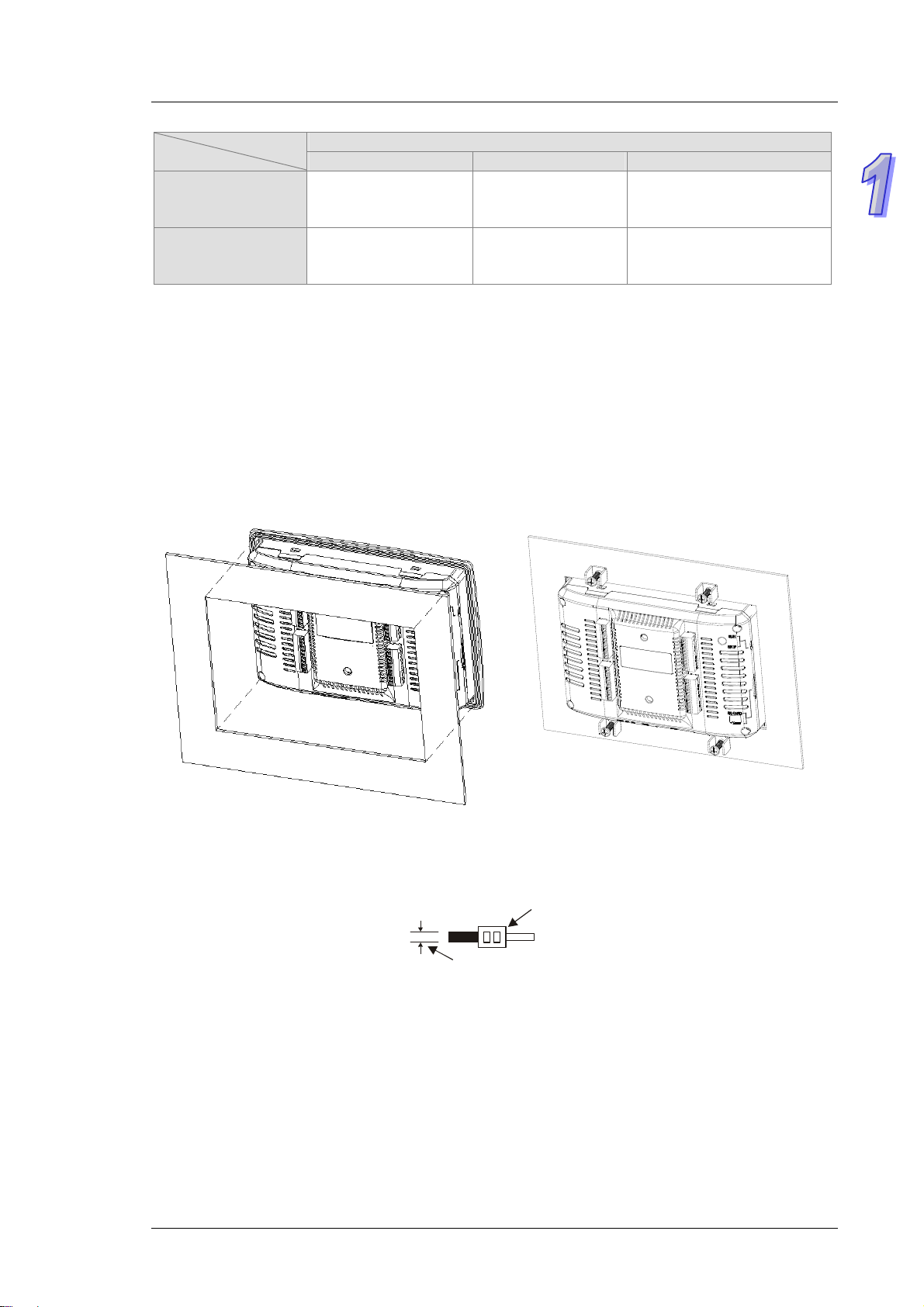
1.7 Installation
Please put (embed) TP70P into a control panel. Use the fasteners and the screws in the container in which
TP70P is packaged. Insert the fasteners into the slots on TP710P, and then tighten the screws. (The torque
applied to the screws should be 4.75 kg-cm. It can not exceed 4.75 kg-cm, otherwise the panel will be
destroyed. If the fasteners are not used correctly, Delta does not guarantee a degree of resistance to water.
Please see the figures below. The control panel should be watertight and dustproof, or meet corresponding
specifications (IP66/NEMA 4).
Please do not install TP70P in the following environments.
Environments in which there are dust, oily smoke, metal powder, and corrosive or flammable gas
High-temperature and humid environments
Environments in which TP70P may be shocked and vibrated directly
Wiring terminals
1. Please connect 22 to 16 AWG (1.5 mm) single-core or twin-core cables to the input/output terminals on
TP70P.
22-16AWG
< 1.5m m
The torque applied to the screws on TP70P should be 1.90 kg-cm (1.65 in-lbs). Only copper leads which
can resist the heat above 60°C/75°C can be used.
2. Please connect 22 to 12 AWG single-core or twin-core cables to the power input connector on TP70P.
(Only copper leads which can resist the heat above 60°C/75°C can be used.) The torque applied to the
screws on the PLC connected to TP70P should be in the range of 5~8 kg-cm (4.3~6.9Ib-in).
3. Please do not wire the terminal . Input cables and output cables should not be put in the same cable tray.
4. When users tighten screws and wire terminals, they should prevent tiny metallic conductors from dropping
into TP70P. After the wiring of TP70P is complete, the users have to ensure that TP70P can radiate heat
normally.
1-11
Page 15

TP70P Quick Start
1.8 Wiring
1.8.1 Wiring a Power Input Connector
The power supplied to TP70P is DC power. When users use TP70P, they have to note the following points.
Please connect wires to the terminals +24V and 0V. The power supplied to TP70P should be in the range
of 20.4 V DC to 28.8 V DC. If the voltage of the power supplied to TP70P is less than 20.4 V DC, TP70P
will stop running, and output devices will be off.
If a power cut is shorter than 10 milliseconds, TP70P will not stop running. If a short cut is long, or the
voltage of the power supplied to TP70P decreases, TP70P will stop running, and output devices will be off.
If power is restored after a power cut, TP70P will automatically resume running. (There are latching
auxiliary relays and retentive registers in TP70P. Users should use them carefully when they design a
program.)
The power supplied to TP70P is DC power. A Delta power supply module (DVPPS02/DVPPS05) can be
used to supply power to TP70P. In order to protect DVPPS02/DVPPS05, users need to have the protection
circuit shown below.
AC
100~240V
50/60Hz
DVPPS02
2A
MC
L
N
24V
0V
24V
AC power supply: 100~240 V AC, 50/60 Hz
Circuit breaker
Emergency stop: An emergency stop button can be used to cut off power when an emergency occurs.
Power indicator
AC load
2 A fuse
Ground (Impedance: Less than 100 Ω)
DC power supply: 24 V DC
TP70
0V FE
1-12
Page 16
Chapter 1 Introduction
O
O
1.8.2 Wiring Input Terminals
The power supplied to input terminals are DC power. There are two types of current. They are sinking current
and sourcing current.
Sinking current
I/
X0
S/S
Sourcing current
I/
X0
S/S
1.8.3 Wiring Relay Output Terminals
Relay output
AC load
Y0
Internal
cir cuit
Internal
circu it
AC power
C0
1-13
Page 17
TP70P Quick Start
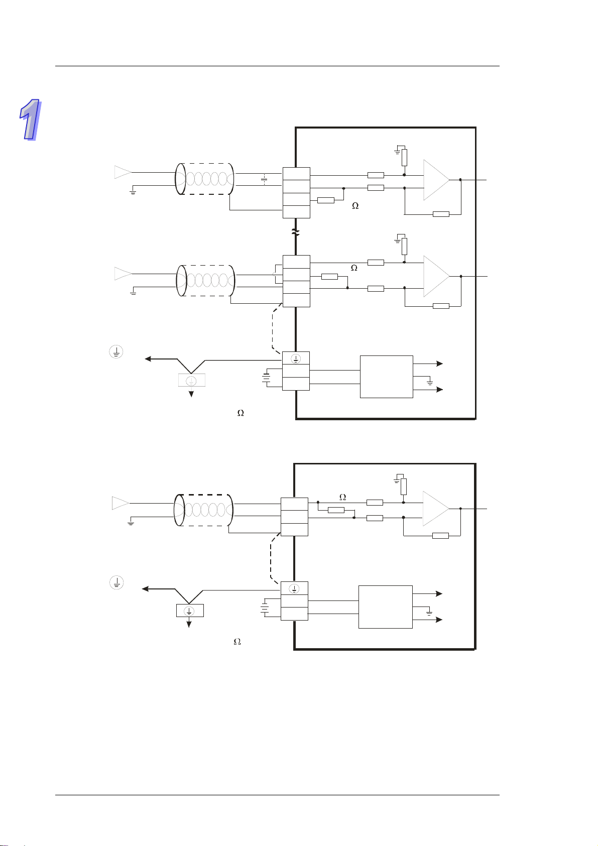
1.8.4 Wiring Analog Input Channels
TP70P-22XA1R
Voltage in p ut
-10V~+10V
Current input
-20mA~+20mA
Connecte d to on a
power supply module
Shiel d ed cable*1
Sh i elded c able*1
*5
System ground
Ground
(Im ped an ce: Les s t han 100 )
*3
*2
*4
DC24V
CH0
CH3
V0+
VI0-
I0+
FE
V3+
VI3-
I3+
FE
0V
24V
250
250
1M
1M
1M
1M
DC/DC
converter
AG
AG
AG
+15V
-15V
CH0
CH3
TP70P-21EX1R
Curr ent in put
-20mA~+20mA
Shielded cable*1
CH0
I0+
I0-
FE
250
1M
1M
AG
*4
Connecte d to on a
power s upply m odule
*5
Syst em groun d
Ground
(Impedance: Les s t han 100 )
DC24V
0V
24V
DC/DC
converter
+15V
AG
-15V
*1: Please isolate analog input cables from other power cables.
*2: If current is connected, the connection between V3+ and I3+ need to be a short circuit.
*3: If ripple voltage results in interference with the wiring, please connect a 0.1~0.47 μF and 25 V capacitor.
*4: If there is much noise, please connect the terminal FE to the ground terminal.
*5: Please connect the ground terminal on a power supply module and the analog inp ut terminal FE to the
system ground, and then ground the system ground or connect the system ground to a distribution box.
CH0
1-14
Page 18
Chapter 1 Introduction
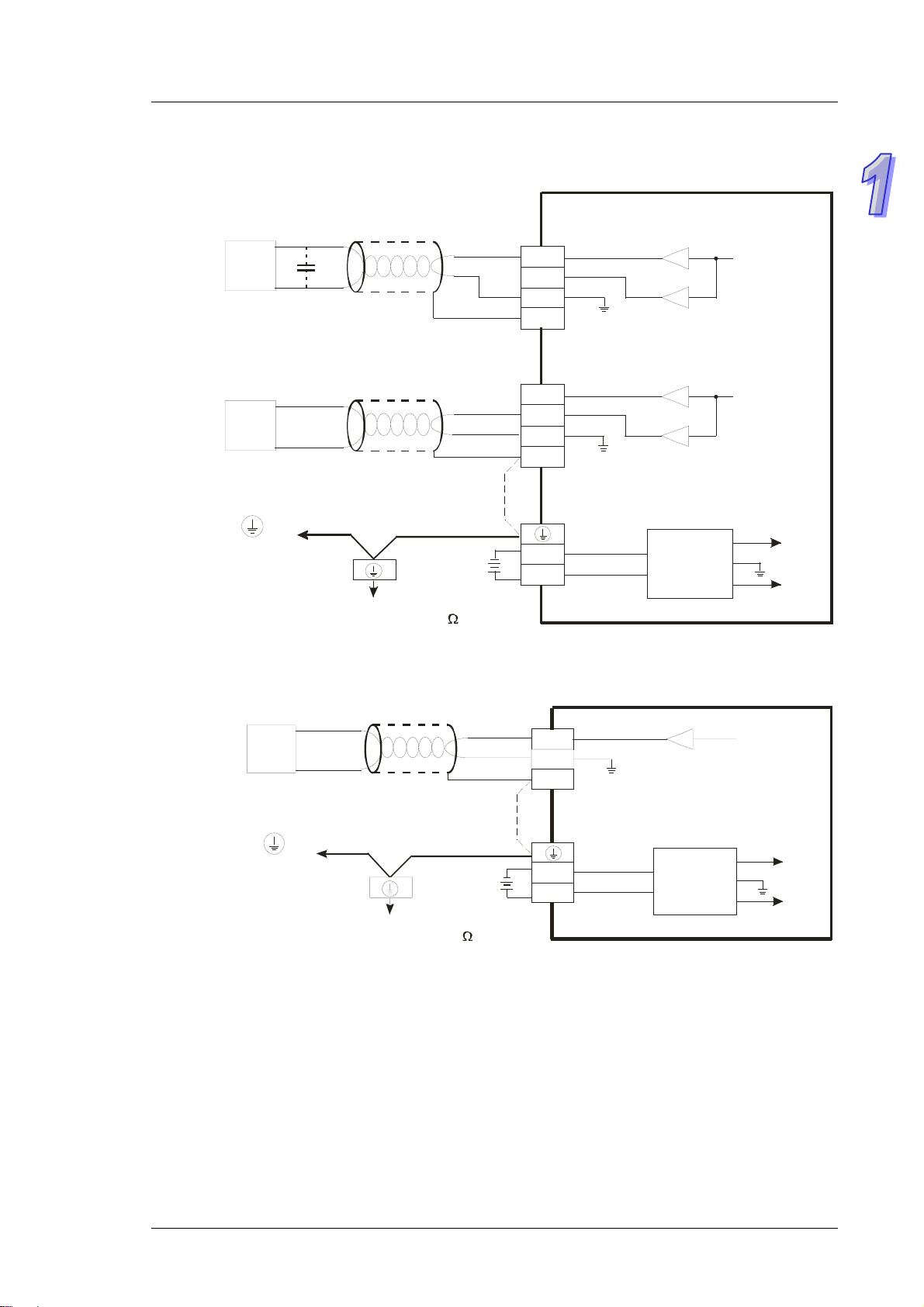
Wiring
1.8.5
TP70P-22XA1R
AC motor drive, recorder,
pro port io nin g val v e. ..
AC motor drive, recorder,
proport io ning v alv e...
Connected to on a
power supply module
TP70P-21EX1R
Analog
*2
(Impedance: Less than 100 )
Output Channels
V oltage outpu t
-10V~+10V
Shielded cable *1
Curr ent output
0mA~20mA
Shielded cable*1
*4
Sys tem ground
Ground
CH4
CH5
*3
DC24V
VO4
IO4
AG
FE
VO5
IO5
AG
FE
0V
24V
AG
AG
DC/DC
converter
CH4
CH5
+15V
AG
-15V
Current output
AC motor dri ve , record e r,
proportioning valve...
Connec te d to on a
power s upply module
0mA~20mA
Shielded cable*1
*4
System ground
Ground
(Impedance: Less than 100 )
CH2
*3
DC24V
IO2
AG
FE
0V
24V
AG
DC/DC
converter
CH2
+15V
AG
-15V
*1: Please isolate analog output cables from other power cables.
*2: If the ripple voltage of the input terminal of the load connected is large, and results in interference with the
wiring, please connect a 0.1~0.47 μF and 25 V capacitor.
*3: If there is much noise, please connect the terminal FE to the ground terminal.
*4: Please connect the ground terminal on a power supply module and the analog outp ut terminal FE to the
system ground, and then ground the system ground or connect the system ground to a distribution box.
1-15
Page 19
TP70P Quick Start
1.8.6 Wiring Temperature Measurement Input Terminals
TP70P-21EX1R
0~300
Ω
Ni100/Pt100
Two-wire
0~300
Ω
Nt100/ Pt100
Three-wire
Shielded cable *1
Shielded ca ble*1
*2
L3+
L3-
I3 FE
L4+
L4-
I4-
FE
1. 66 m A (Ni100, P i1 00 ,
resist or)
AG
1. 66 m A (N i1 00 , P t100 ,
resistor)
AG
Connec t ed to on a
power supply module
*3
Syst em ground
Ground
(Im ped anc e: Less than 100 )
DC24V
0V
24V
DC/DC
converter
+15V
AG
-15V
*1: The cables connected to the input terminals should be cables or shielded twisted pair cables which can be
connected to temperature sensors, and should be kept separate from other power cables and cables which
may generate noise.
*2: If there is much noise, please connect the terminal FE to the ground terminal.
*3: Please connect FE on a power supply module and the temperature measurement input terminal FE to the
system ground, and then ground the system ground or connect the system ground to a distribution box.
*4: Please do not wire the terminal .
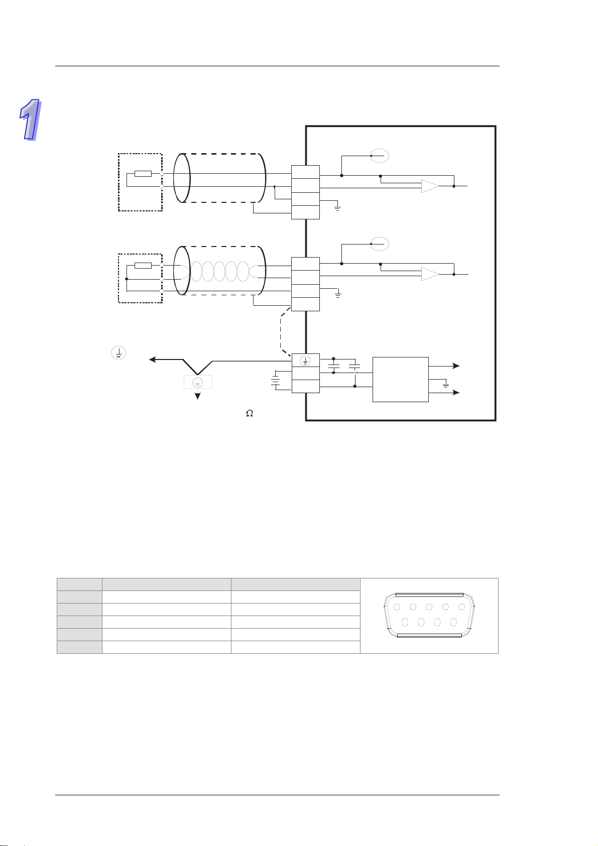
1.9
Definitions of the Pins in Communication Ports
TP70P-16TP1R, TP70P-21EX1R, TP70P-22XA1R, TP70P-32TP1R
Pin RS-485 (COM2) RS-485 (COM3)
5 GND GND
6 D+ N/C
7 D- N/C
8 N/C D+
45
3
89
12
67
9 N/C D-
1-16
Page 20
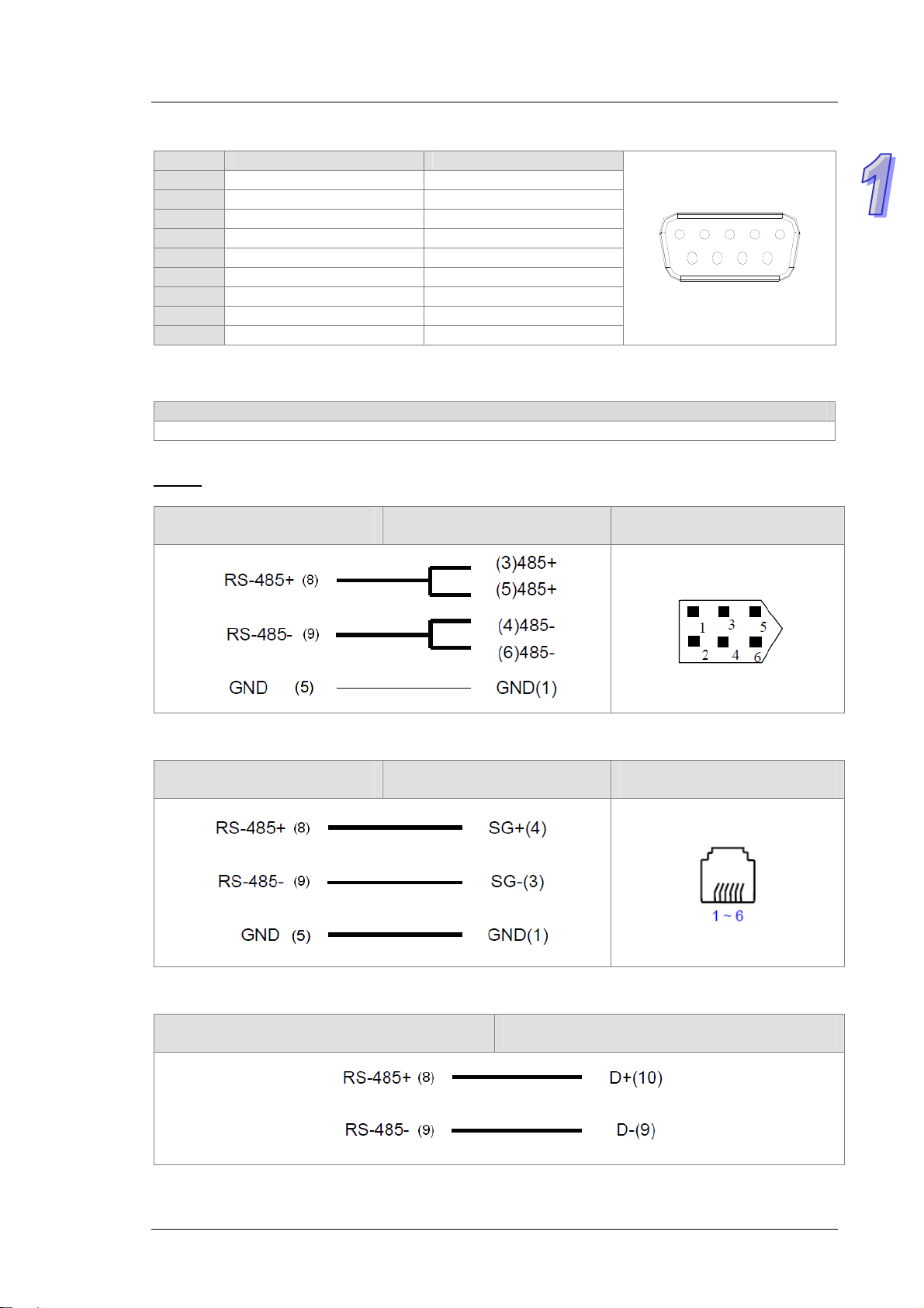
TP70P-RM0
Pin RS-232 (COM2) RS-485 (COM3)
1 N/C N/C
2 RX N/C
3 TX N/C
4 N/C N/C
5 GND GND
6 N/C D+
7 N/C D-
8 N/C N/C
9 N/C N/C
Chapter 1 Introduction
45
3
89
12
67
1.10
Wiring:
Controllers
Delta servers, Delta AC motor drives, Delta temperature controllers, and Delta PLCs
Delta server
TP70P
COM3 (RS-485)
Delta AC motor drive
TP70P
COM3 (RS-485)
Supporting TP70P
Controllers supporting TP70P
Controller
Male CN3 connector (RS-485)
Controller
RJ11 connector (RS-485)
Pins in a male CN3 connector
Pins in an RJ11 connector
Controller
Controller
Delta temperature controller
TP70P
COM3 (RS-485)
Controller
RS-485
1-17
Page 21

TP70P Quick Start
Delta PLC
COM3 (RS-485)
TP70P
Controller
RS-485
1-18
Page 22

Chapter 2 Writing Programs
Table of Contents
2.1 Preparations..............................................................................2-2
2.1.1 Hardware............................................................................2-2
2.1.2 Software............................................................................. 2-2
2.1.3 Tools and Materials............................................................... 2-2
2.2 Wiring......................................................................................2-2
2.2.1 Wiring Diagram for a Delta VFD-M Series AC Motor Drive...........2-3
2.2.2 Wiring Diagram for External Terminals ....................................2-3
2.2.3 Wiring Diagram for Communication ........................................2-3
2.2.4 Setting Parameteres in a Delta VFD-M Series AC Motor Drive .....2-4
2.3 Example ...................................................................................2-4
2.4 Writing a Program for a Text Panel ...............................................2-5
2.4.1 Planning Objects..................................................................2-7
2.4.2 Managing Pages...................................................................2-7
2.4.3 Creating Objects.................................................................. 2-8
2.4.4 Basic Configuration ............................................................2-15
2.4.5 Compile and Downloading a Program....................................2-16
2.5 Writing a Program for a PLC ......................................................2-18
2.5.1 Planning a Program............................................................2-20
2.5.2 Control Program ................................................................2-21
2.5.3 Compile and Downloading a Program....................................2-22
2.6 Monitoring and Debugging a Program .........................................2-23
2.6.1 Monitoring a Program .........................................................2-23
2.6.2 Remo ving System E rrors.....................................................2-27
2-1
Page 23

TP70P Quick Start
2.1 Preparations
2.1.1 Hardware
The hardware required is list below.
1. TP70P-16TP1R 2. Power supply module DVPPS02 3. VFD-M series AC motor drive
2.1.2 Software
The software required is listed below.
WPLSoft version 2.36 or above
TPEditor version 1.9 or above
2.1.3 Tools and Materials
The tools and the materials which are required are list below.
One personal computer (The software mentioned above has been installed. )
One 100~240 V AC and 50/60 Hz power supply
One coil of wire
One screwdriver
One USB cable (Pleae refer to section 3.1 for more information about installing a USB driver.)
2.2 Wiring
After users install a text panel, they can wire the text panel. In order to ensure that the users can write
programs smoothly, the users need to at least connect power cables. Please connect power cables to a text
panel when the text panel is disconnected. The structure required is like the one shown below.
2-2
Page 24

Chapter 2 Writing Programs
2.2.1 Wiring Diagram for a Delta VFD-M Series AC Motor Drive
NFB
R
S
T
Recommended
circuit used when
the pow er supply is
turned OF F by a f aul ty output
Factory default
Analog voltage
Analog current
Main circuit terminal
Control circuit terminal
Shielded lead
The specifications for the main
circuit terminal is M3.0.
OFF
Stopping forward
rotation
Stopping backward
rotation
Resetting
Multi-speed
com m and 1
Multi-speed
command 2
Multi-speed
command 3
Common signal
Master frequency setting
Factory default: VR on the
digital keypad
3
0~10VDC
VR: 3k~5kΩ
4~20mA
VR
1
2
SA
MC
ON
MC
If it is a single phas e, please sel ect any two input power termi nals in the main circ uit power.
*
* Three-phase power can be input to a single phase model.
※ Please refer to VFD-M User Manual for more information.
Brake resistor (optional)
B1
R(L1)
S(L2)
T( L3 )
RB
RC
M0
M1
M2
M3
M4
M5
GND
E
Powe r for speed setting
+10V 10mA(MAX)
AVI
ACI
GND
RS-485
serial
communication
B2
U(T1)
V(T2)
W(T3)
RA
RB
RC
MO1
MCM
AFM
GND
RJ-11
61
AC motor
M
3~
E
E
←
Third ground
230 series: The impedance is less than 100 .Ω
460 series: The impedance is less than 10 .Ω
Multi-function indication output contact
120VAC/250VAC, 5A
24VDC, less than 2.5A
Factory default: Indicati ng a malfunction
Multi-function photocoupler output contact
48VDC 50mA
Factory default: Indic ating operation
VR(1k )Ω
For adjustment
Analog output
+
DC 0~10V
-
Factory default: Output frequency
1: 15V
2: GND
3: SG4: SG+
5: NC
6: For communication
2.2.2 Wiring Diagram for External Terminals
TP70P series text panel
External I/O connector
C0 GND
Y0 M0
Y1 M1
VFD-M series AC motor drive
2.2.3 Wiring Diagram for Communication
TP70P
COM3 (RS-485)
RJ11 connector (RS-485)
Controller
Controller
Pins in an RJ11 connector
2-3
Page 25

TP70P Quick Start
2.2.4 Setting Parameteres in a Delta VFD-M Series AC Motor Drive
Parameter Setting Description
P00 03 A master frequency is determined by an RS-485 port.
P01 01
P03 60 Maximum operating frequency (50.00~400.0 Hz)
P08 1.50 Minimum output frequency (0.10~20.00 Hz)
P88 01 The communication address of the VFD-M series AC motor drive is 1.
P89 01 Baud rate: 9600 bps
P92 01
※ If an AC motor dirve can not operate normally due to the fact that parameters are not set correctly,
users can set P76 to 10 (restore all parameters to the default value 60 Hz), and then set other
parameters according to the table above.
Operation is controlled by external terminals. STOP on a keypad is
effective.
MODBUS ASCII mode
Data format: <7, E, 1>
2.3 Example
After users install, wire and power up hardware, they can prepare to write programs. In order to make the users
have a specific target and a specific direction before they begin to write programs, the manual provides a
common example for the users. The complete procedure which starts with the creation of a new project and
ends with the downloading of the project to a PLC is described step by step.
Structure of a system
Start (Y0)
Stop (Y1)
Rotational speed
command (COM3)
Current rotational
speed (COM3)
Alarm(C OM3 )
Control
The communication between a PLC and a Delta VFD-M series AC motor drive is described here. Y
devices on TP70P are used to control the forward/backward rotation of the AC motor drive. RS-485
communication (COM3) is used to read/set the frequency of signals output by the VFD-M series AC motor
drive. If the AC motor drive breaks down, an alarm signal in the AC motor dirve will be sent to TP70P.
Actions:
1. If the AC motor drive rotates forwards, its forward rotation indicator will be on, and the input which makes
the the AC motor drive rotate barckwards will be ineffective.
2. If the AC motor drive rotates backwards, its backward rotation indicator will be on, and the input which
makes the the AC motor drive rotate forwards will be ineffective.
3. If stop control is input, the operation of the AC motor drive will stop, and its stop indicator will be on.
4. The users can input a frequency range. The frequency range that the users set should be between the
maximum operaring frequency of the AC motor drive and the minimum operaring frequency of the AC
motor drive.
5. If the AC motor drive sends an error code, the operation of the AC motor drive will stop.
I/O devices in the PLC:
1. Forward rotation control (M0)
2. Backward rotation control (M1)
3. Stop control (M2)
4. Forward rotation switch (Y0)
2-4
Page 26

Chapter 2 Writing Programs
5. Backward rotation swithc (Y1)
6. Stop indicator (M3)
Objects displayed on TP70P:
1. Forward rotation control
2. Backward rotation control
3. Stop control
4. Rota
5. Forward rotation indicator
6. Backward rotation indicator
7. Stop indicator
8. Current rotational speed
9. Warning message
tional speed input
2.4 Writing a Program for a Text Panel
The writing of a program for a text panel is described in this section. Please refer to TPEditor User Manual for
more infomraiton about the functions of TPEditor.
Step 1: Start TPEditor. (
)
x.xx
Welcom screen
StartProgramsDelta Industrial AutomationPLCTPEditor x.xxTPEditor
Main screen
2-5
Page 27

TP70P Quick Start
Step 2: After on the standard toolbar is cliked, a new project will be added. In the
select
DELTA VFD Inverter
type “TP70-VFD CTRL” in the
After OK in the
New
Project
in the
HMI<=>PLC
File Name
window is clicked, a project environment will be displayed.
section, select
box.
in the
TP70P
TP Type
drop-down list box, and
New Project
window,
The interface of TPEditor is described below. Please refer to TPEditor User Manual for more information.
Menu bar, standard toolbar, and object arrangement toolbar: The main functions of TPEditor are included.
The functions which are used more frequently are on the standard toolbar, and the functions which are used
less frequently are on the menu bar.
Geometric object toolbar and object toolbar: They provide buttons used for drawing figures and creating
buttons. There are some other objects on the
Page management area: Users can view/add/delete pages.
Working area: Users can edit pages in this area.
Status bar: The information about the current project and communication is displayed here.
Object
menu.
2-6
Page 28

Chapter 2 Writing Programs
2.4.1 Planning Objects
After users make sure of system requirements, they can plan messages which need to be displayed. The
objects and the pages which need to be planned for the example in this chapter are described below.
Planning objects
Forward rotation controlA button is used. After users press the button, the AC motor drive connected will
rotate forwards.
Backward rotation controlA button is used. After users press the button, the AC motor drive connected
will rotate backwards.
Forw
Backward rotation indicatorA multi-state image is used. If the AC motor drive connected rotates
Stop indicatorA multi-state image is used. If the AC motor drive connected stops running, a red indicator
Current rotational speedA numeric display is used. The current rotational speed of the AC motor drive
Error messageA message display is used. The state of the AC motor drive connected can be monitored
Rotational speed inputA numeric input is used. A frequency can be written to the AC motor drive
Planning pages
Plan a boot page on which the connection between TP70P and a VFD-M series AC motor drive is
The state of the AC motor drive used is displayed on page 0, that is, the current rotational speed of the AC
ard rotation indicatorA multi-state image is used. If the AC motor drive connected rotates forwards,
a green indicator will be on, and a message saying that the AC motor drive rotates forwards will appear.
backwards, a yellow indicator will be on, and a message saying that the AC motor drive rotates backwards
will appear.
will be on, and a message saying that the AC motor drive stops running will appear.
connected can be read by means of RS-485 communication.
by means of RS-485communication. If an error code in the AC motor drive connected is read, the error
message corresponding to the error code will be displayed on the text panel used.
connected by means of RS-485 communication. If a minimum value and a maximum value are typed in the
Limit Setting
minimum operating frequency of the AC motor drive connected to the maximum operating frequency of the
AC motor drive connected.
displayed.
motor drive, a warning message, forward rotation control, backward rotation control, and stop control are
displayed on page 0.
section, users can be prevented from setting a frequency which is not in the range of the
2.4.2 Managing Pages
Adding a page
Users have to add to two pages first. After the users right-click
click
on the context menu which appears, a page will be added.
Add
1
2
TP Page
in the page management area, and
2-7
Page 29

TP70P Quick Start
Editing the title of a page
The users have to give names to the two pages. After the users right-click a page number in the page
management area, and click Edit on the context menu which appears, they can type a page title.
1
2
2.4.3 Creating Objects
After users click an object on the object toolbar, they can click where they want to begin the selection of an area
in the working area, hold down the left mouse button, and drag the cross over the area that they want to select.
After the users double-click the object in the working area, the window used for setting the object will be
opened.
The objects on the object toolbar are described below. Please refer to TPEditor User Manual for more
information.
Static Bitmap
pixels. If the size of an image exceeds the resolution, the part which is left will not be displayed.
Static Text
Numeric/ASCII Display
TP70P.
Bar Graph
value, the maximum value, and the minimum value which are set.
Circle Meter
on the dial of a meter points. The upper limit set can be differentiated from the lower limit set by means of
the region colors set.
Messge Display
by a message displayed on the screen of TP70P.
Button
function can be set, e.g. the page selected will be displayed or passwords can be set.
RTC Display
time in related devices will be read and dispalyed on the screen of TP70P.
(
): The files that TP70P supports are .gif files. The resolution of TP70P is 480×800
): Text is displayed.
(
( ): The value in a related device is read, and displayed on the screen of
): The value in a related device is read, and represented by a bar according to the target
(
( ): The value in a related device can be represented by the number to which the poi nter
( ): The state of a related device or the value in a related device can be represented
):After users press a button, the state of the device related to the button will be changed, or a
(
): The time on the real-time clock in TP70P is displayed on the screen of TP70P, or the
(
2-8
Page 30

Chapter 2 Writing Programs
Mlulti-State Bitmap/Lable
image. The difference between a multi-state image and a dynamic image is that text can be inserted in a
multi-state image.
Numeric Input
related device.
X-Y Curve
screen of TP70P.
The users have to plan pages and add object. They have to add an image representing the connection
between TP70P and an AC motor drive to the boot page. They need to click
where they want to begin the selection of an area in the working area, hold down the left mouse button, and
drag the cross over the area that they want to select. After the users double-click the object in the working area,
an
Open
(
Alar
m
appear.
(
Slider
TP70P.
window will appear. After the users select a .gif file, an image will appear in the working area.
(
): The values in related devices can be represented by an X-Y curve displayed on the
(
): An alarm and a system alarm are used together. If a condition set is met, an alarm will
): Users can write a value to a related device by move the indicator on a slider displayed on
( ): The function of a multi-state image is the same as that of a dynaic
): A numeric input displayed on the screen of TP70P is used to write a value to a
on the object toolbar, click
The state of the AC motor drive used is displayed on page 0, that is, the current rotational speed of the AC
motor drive, a warning message, forward rotation control, backward rotation control, and stop control are
displayed on page 0.
2-9
Page 31

TP70P Quick Start
If the users want to add an object to a page, they have to click an object type on the object toolbar, click where
they want to begin the selection of an area in the working area, hold down the left mouse button, and drag the
cross over the area that they want to select.
ter the users add an
Af
button in the working area, the
is used to control the forward rotation of an AC motor drive. If a button is pressed, M0 will be ON. If M0 is ON,
Y0 will be ON. If the button is pressed again, M0 will be OFF. Consequently, the button type selected in the
Button Type
Refer Device
drop-down list box is
window are selected.
object, they have to set the parameters related to be object. After users double-click a
Button Setting
Push On/Off
window will appear. In the example in this chapter , Y0 in TP70P
, and the
Internal PLC Setting
option button and M0 in the
2-10
Page 32

Chapter 2 Writing Programs
After the users click the
appearance of the object. After the users click the
a value in the a
select an image in the
In the example in this chapter, “FORWARD” need to be displayed on the forward rotation control button created
if the forward roation control button is not pressed yet, and “Running…” need to be displayed on the rotation
control button created if the forward roation control button is pressed. Consequently, the users have to type
“FORWARD” in the
type “Running” in the
click OK in the
will be complete.
Border Width
Button Setting
Property
States
Button Text
Button Te x t
tab in the window used to set the parameters of an object, they can set the
Property
box, select colors in the
section. The text displayed on a button varies with the current state of the button.
when 0 in the
when 1 in the
window, the setting of the p arameters and the appearance of the button created
Current State
Current State
tab in the
Button Event Color Setting
drop-down list box is selected, and they have to
Button Setting
drop-down list box is selected. After the users
window, they can select
section, and type text or
2-11
Page 33

TP70P Quick Start
If the users want to make a copy of an object in the working area, they have to click the object, right-click the
object, click
menu which appears. If the users want to make several copies of an object in the working area, they have to
click the object, right-click the object, click
checkboxes, values or an option button in the
Singe copy:
on the context menu which appears, right-click the object, and click
Copy
Multi-Copy…
Multi-Copy
on the context menu which appears, select
window, and click OK.
on the context
Paste
Multiple copies:
2-12
Page 34

Chapter 2 Writing Programs
The users can complete the page shown below in the way described above.
Setting the parameters of objects:
Item
1
2
3 Stop control
4
5
6 Stop indicator
7
8
Object
description
Forward
rotation control
Backward
roation control
Forward
rotation
indicator
Backward
rotation
indicator
Rotational
speed input
Current
rotational
speed
Button/Objec
t type
Push On/Off
Push On/Off
Momentary
Multi-State
Bitmap/Lable
Multi-State
Bitmap/Lable
Multi-State
Bitmap/Lable
Numeric
Input
Numeric/ASC
II Dispaly
Internal PLC M0 -
Internal PLC M1 -
Related device
Communication
method
Internal PLC M2 -
Internal PLC Y0
Internal PLC Y1
Internal PLC M3
COM3, station
address 1
COM3, station
address 1
Device
address
$2001
$2102 -
Other settings
Background color (1/0):
Green/White
Background color (1/0):
Yellow/White
Background color (1/0):
Red/White
In the
Value Setting
Integer Number
Decimal Number
In the
Limit Setting
Max Value
Min Value
: 600
: 15
section:
: 3
: 2
section:
2-13
Page 35

TP70P Quick Start
Item
9 Error message
Object
description
Button/Objec
t type
Message
Diaplay
Related device
Communication
method
COM3, station
address 1
Device
address
$2100
Other settings
Total States
Display Sequence: From Min
to Max
Current State (Device
Value>=Range Value
refer to the table below.
0 No error occurs.
1 Overcurrent
2 Overvoltage
3 Overheating
4
5
6 External fault
7 CPU failure
8
9
10
11
12
13 Ground fault
14 Low voltage
15 Reserved
16 CPU failure
17 Base block
18 Overload
19
20
: 21
): Please
The drive is
overloaded.
The motor is
overloaded.
CPU failure or analog
circuit failure
Hardware protection
failure
There is overcurrent
during the
acceleration.
There is overcurrent
during the
deceleration.
There is overcurrent
during the steady
operation.
Automatic
acceleration/decelerati
on failure
The software
protection is enabled.
2-14
Page 36

2.4.4 Basic Configuration
Chapter 2 Writing Programs
After users click
TP <=> PLC Protocol
PC <=> TP Communication Setting
Before users dow
personal computer, they have to click
window. The users have to use a USB cable to connect the text panel to the personal computer. The
communication ports on the personal computer are displayed in TPEditor. After the users select the
communication port which is connected to the text panel, they can download the program in TPEditor to the text
panel, or upload the program in the text panel to the personal computer.
Basic Configuration
, or
TP Other Setting
nload the program in TPEditor to a text panel, or upload the program in a text panel to their
on the
PC <=> TP Communication Setting
menu, they can click
Tool
in the
Basic Configuration
PC <=> TP Communication Setting
window.
in the
Basic Configuration
,
TP <=> PLC Protocol
After users click TP <=> PLC Protocol in the Basic Configuration window, they can set a communication
protocol between a text panel and an external device. The text panel can be connected to the external device
only if the communication protocol of the text panel and the communication of the external device are the same.
In the example in this chapter, the communication protocol between the VFD-M series AC motor drive used and
TP70P is “9600, 7, E, 1”.
2-15
Page 37

TP70P Quick Start
TP Other Setting
After users click
the brightness of the backlight that illuminates the screen of TP70P, enable the buzzer of TP70P, set a
password, select a boot page, etc. In the example in this chapter, a user-defined boot page is designed, and
therefore the
TP Other Setting
User Define
option button in the
in the
Basic Configuration
Start-Up Menu Display
window, they can select a station address, set
section is selected.
2.4.5 Compile and Downloading a Program
After users write a program, and adjust related settings, they can download the program to a text panel. The
users have to compile the program first. After the users click
standard toolbar, the program will be compiled. If the program is compiled successfully, the percentage of
memory used will be shown.
Build All
on the
Compile
menu, or on the
2-16
Page 38

Chapter 2 Writing Programs
After the program is compiled, the users can download the program. After the users click
Communication
ter the users make sure of the pa
Af
Setting
After the transmission of the program is complete, a message saying the the downloading of the program is
complete will appear.
window, the
menu, or on the standard toolbar, the
ges which need to be downloaded, and click
Confirm
window will appear.
Download Setting
window will appear.
Download
Write to TP
in the
on the
Download
2-17
Page 39

TP70P Quick Start
2.5 Writing a Program for a PLC
TP70P can be used to integrate control, and execute and display functions. The conditions which control
actions can be created in a PLC program. The writing of a program for the PLC used in the example in this
chapter is described below. The Delta software which supports TP70P is WPLSoft and ISPSoft. Please refer to
WPLSoft User Manual and ISPSoft User Manual for more information about the usage of WPLSof and ISPSoft.
In the example in this chapter, WPLSoft version 2.36 is used to write a program for the PLC used.
Step 1: Start W
)
2.36
Welcom screen
PLSoft. (
StartProgra
m
sDelta Industrial AutomationPLCWPLSoft 2.36WPLSoft
Main screen
2-18
Page 40

Chapter 2 Writing Programs
Step 2: After is cliked, a new project will be added. In the
CTRL” in the
example” in the
Step 3: Af
will appear. Select
connected to TP70P. The communication protocol set in the
communication protocol of TP70P. The default communication protocol set in the
window is “9600, 7, E, 1”. Select 1 in the
Communication Setting
Program Title
File Name
ter
Se
tting
RS232
box, select
box.
in the
Communication Setting
in the
Type
window is complete.
TP70P/TP70G
drop-down list box, and select the communication port which is
Station A ddress
in the
section is clicked, the
Select a PLC Model
drop-down list box, and type “TP70
Select
Communication Setting
Communication Setting
box. Click OK after the adjustment of settings in the
window, type “TP70-VFD
window
window need to be the
Communication Setting
2-19
Page 41

TP70P Quick Start
After OK in the
program title set will appear in the upper left corner of the
Communication Setting
window is clicked, a project environment will be displayed (the
Delta WPLSoft
windo w).
2.5.1 Planning a Program
In order to meet the requirements of the system used in the example in this chapter, the following conditions
need to be planned.
Planning devices
M0Forward rotation control
M1Backward rotation control
M2Stop control
M3Stop flag
Y0Forward rotation output
Y1Backward rotation output
Planning actions
If M0 is ON, Y0 will be ON.
If M1 is ON, Y1 will be ON.
If M2 is ON, Y0 and Y1 will be OFF.
If Y0 is ON, M1 will be ineffective.
If Y1 is ON, M0 will be ineffective.
If Y0 and Y1 are OFF, the AC motor drive used will stop running, and M3 will be ON.
2-20
Page 42

Chapter 2 Writing Programs
2.5.2 Control Program
The control program shown below is created according to the conditions planned in section 2.5.1. Please refer
to WPLSoft User Manual for more information about the usage of WPLSoft.
2-21
Page 43

TP70P Quick Start
2.5.3 Compiling and Downloading a Program
After users write the program shown in section 2.5.2, they can download the program to TP70P. The users
have to compile the program first. After the users click
on the standard editing toolbar, the program will be compiled. The result of the comipiling of the program is
shown in the message area in WPLSoft.
Ladder => Instruction
on the
Compiler
menu, or
After the program is compil
window will appear. The users can select checkboxes in the
Setup
that there are comments on the devices in the program, the
window is selected.
ed, the users can download the program. After the users click
Transfer Setup
Device Comment
, the
window. Owing to the fact
checkbox in the
Transfer Setup
Transfer
2-22
Page 44

Chapter 2 Writing Programs
After the users select the
select devices and set device ranges.
Device Comment
checkbox, the
System Block
window will appear. The users can
After the users click OK in the
Transfer Setup
window, the program will be downloaded to TP70P.
2.6 Monitoring and Debugging a Program
2.6.1 Monitoring a Program
When a program is executed by a system, users can understand the current logic state of the system by
monitoring the program, or test the system by chaning the values in devices.
Minotring a program
Users have to open the program which has been compiled in section 2.5.3.
After the users click
and the information related to devices. (The states of Boolean devices are indicated by green backgrounds
or white backgrounds, and the information about other devices is indicated by values or text.)
, the program will be monitored. The program is composed of a logic program,
2-23
Page 45

TP70P Quick Start
If the users want to chage the state of a device, they can right-click the device, and click an item on the
context menu which appears. In the figure below, M0 is set to ON.
Note:
device because the state of the actual I/O device immediately overwrites the value which is set.
and
Force OFF
Set On
and
can be used instead.
can not be used to change the state of a device corresponding to an actual I/O
Set Off
Force ON
2-24
Page 46

Chapter 2 Writing Programs
Minotring devices
It is sometimes inconvenient for users to search for devices in a logic program that the users test, and
change the values in the devices because the devices are in different sections of the logic program.
Besides, sometimes the purpose of modifying the values in devices in a program is not to debug the
program, but to test an external device. If the users want to change the values in devices in a program by
monitoring the program, they may not easily find the devices, and they need to have the program. To solve
these problems, the users can use a device monitoring table. If the users change the values in devices in a
program by means of a device monitoring table, they do not even need the program.
The users have to click
After the users type a device name and the number of devices, and click
window, devices will be brought into the device monitoring table.
input
, and then double-click the device monitoring table which appears.
in the
Input
Device monitor
2-25
Page 47

TP70P Quick Start
The states of the devices broght into the device monitoring table will be shown only if
If the users want to chage the state of a device, they can right-click the device, and click an item on the
context menu which appears. M0 is set to ON here. When M0 is ON, Y0 is ON, the AC motor drive used
rotates forwards, and the users can see that the forward rotation indicator on the screen of TP70P is
green.
is pressed.
2-26
Page 48

Chapter 2 Writing Programs
2.6.2 Removing System Errors
When a system runs, errors may occur. If users follow the procedure introduced in this chapter, there will be no
error. After a program is written to a PLC, M1004 will be ON if an error occurs. The reason for the error may be
that operands (devices) are invalid, or syntax is incorrect. It is indicated by the error code (hexadecimal value)
in D1004. D1004 can be monitored by means of WPLSoft.
1. Click
Edit Monitored Devices
on the
menu in WPLSoft.
View
2-27
Page 49

TP70P Quick Start
2. After is clicked, the value in D1004 will be shown.
3. The error code shown in the figure above is HD03. It indicates that the operands of the instruction DHSCS
are invalid. After DHSCS is checked, and the operands are modified, the error will be eliminated.
2-28
Page 50

Chapter 3 Frequently Asked Questions and
Answers
Table of Contents
3.1 Installing a USB Driver ...............................................................3-2
3.2 Descriptions of the Communication Ports on TP70P.........................3-4
3.3 Setting COM2............................................................................3-5
3.4 Using COM2 as a Master St ation...................................................3-6
3.5 Setting COM3............................................................................3-7
3.6 Setting an RTU Mode for COM3....................................................3-9
3.7 Using COM3 as a Slave Station ..................................................3-10
3.8 Data Exchange ........................................................................3-12
3-1
Page 51

TP70P Quick Start
3.1 Installing a USB Driver
Question】How to install a USB driver?
【
Answer】If users use TP70P for the first time, they have to follow the steps below, and install a USB driver.
【
1. Download the latest version of TPEditor from the official website of Delta, and install the software. (Official
website of Delta: http://www.delta.com.tw
2. After a USB cable is connected to a USB port on the computer, the
will appear. Please select the
.
Next
Install from a list or specific location (Advanced)
)
Found New Hardware Wizard
option button, and click
window
3. Select the
directory where TPEditor is installed, and click
Automation\TPEditor X.X\USB)
Include this location in the search
checkbox, select the
. (Default path: C:\Program Files\Delta Industrial
Next
folder contained inside the
USB
3-2
Page 52

Chapter 3 Frequently Asked Questions and Answers
4. After the installation of the USB driver selected is complete, the communication port connected to TP70P
will be displayed in the
5. The communication port which is conn ected to TP P is also shown in the
Communication Setting (PC <=> TP)
Ports (COM & LPT)
section in the
70
section in TPEditor.
Device Manager
windo w.
PC COM Port
box in the
PC
6. TP70P can communicate with the computer by me ns of the communication port. TPEditor is used to
upload/download a text panel program, and WPLSoft is used to upload/download/monitor a PLC progra
a
m.
3-3
Page 53

TP70P Quick Start
3.2 Descriptions of the Communication Ports on TP70P
Question】What are the differences among the communication ports on TP70P, and methods of setting the
【
communication ports, and how to set them?
Answer】There are three communication ports on TP70P . The modes that the communication ports supports
【
are different, and the methods of setting the communication ports are also different. Please refer to the table
below for more information. COM1, COM2 and COM3 can be used simultaneously. The station address of
COM1 and the station address of COM2 are the same. The station address of COM3 is different from the
station address of COM1 and the station address of COM2.
Communication port Interface Mode supported
COM1 supports connection to software,
COM1 USB
COM2 *1 PLC mode
COM3 *1 Text panel mode
*1. Please refer to section 1.9 for more information.
COM1
COM1 can not function as a master station. It only supports the uploading/downloading of a program. If users
use COM1 for the first time, they need to install a USB driver so that the computer can identify the virtual
communication port which is connected to COM1. Please refer to section 3.1 for more information about
installing a USB driver.
COM2
COM2 can be used as a master station or a slave station. It supports ASCII/RTU communication. Users can set
a serial transmission rate. The maximum transmission rate which can be set is 115 kbps. The users can set the
number of data bits, a parity bit, and the number of stop bits. If RTU communication is used, the number of data
bits must be eight. D1120 in the PLC is used to set a communication protocol. If a communication error occurs
in COM2, the users can check special M devices.
COM3
COM3 supports the text panel. After a driver is selected, COM3 can function as a master/slave station, and
support ASCII/RTU communication. Users can set a serial transmission rate. The maximum transmission rate
which can be set is 115 kbps. The users can set the number of data bits, a parity bit, and the number of stop
bits. If a communication error occurs in COM3, a warning window showing that a communication error occurs
will appear on the screen of the text panel.
and the uploading/download of a
program.
Method of setting a
communication port
Users have to install a
USB driver if COM1 is
used for the first time.
COM2 is set by means of
special D devices and
special M devices in the
PLC.
COM3 is set by means of
objects in the text panel.
3-4
Page 54

Chapter 3 Frequently Asked Questions and Answers
3.3 Setting COM2
Question】How to set COM2?
【
Answer】COM2 supports the PLC. It is set in the same way as a DVP series PLC is. It is set by means of
【
special D registers and special M devices. Please refer to the table below for more information.
Communication parameter Register
Communication format D1120
The communication set holds. M1120
ASCII (Off)/RTU (On) mode M1143
Slave station address D1121
Communication timeout D1129
A communication timeout occurs. M1129
Users can set a communication protocol according to the table below.
b0
b1
b2
b3
b4
b5
b6
b7
b8
b9
b10
b11~b15
Example: COM2 uses ASCII communication.
If the communication format that COM2 uses is the ASCII communication protocol (9600, 7, E, 1), the program
code below must be added to the top of the program in the PLC. When the PLC runs during the first program
scan, it checks whether M1120 is ON. If M1120 is ON, the setting of COM2 will be changed according to the
value in D1120.
Data length
Parity bit
Number of stop bits
Serial transmission rate
Start-of-text character None D1124
First end-of-text character None D1125
Second end-of-text character None D1126
undefined
Contents
0: 7
1: 8
(If RTU communication is used, the number of data bits
set must be 8.)
00: None
01: Odd
11: Even
0: 1 bit
1: 2 bits
0001 (H1): 110
0010 (H2): 150
0011 (H3): 300
1011 (H4) 600
0101 (H5): 1200
0110 (H6): 2400
0111 (H7): 4800
1000 (H8): 9600
1001 (H9): 19200
1010 (HA): 38400
1011 (HB): 57600
1100 (HC): 115200
1101 (HD): 500000
1110 (HE): 32150
3-5
Page 55

TP70P Quick Start
Example: COM2 uses RTU communication.
If the communication format that COM2 uses is the RTU communication protocol (9600, 8, E, 1), the program
below will be required.
Notes:
1.
After the modification of the communication format that COM2 uses is complete, the communication format
that COM2 uses will not change if the PLC stops running.
2. After the modification of the communication format that COM2 uses is complete, the communication
protocol that COM2 uses will be the default communication protocol (9600, 7, E, 1) if the PLC is turned off
and then powered when it stops running.
3. If COM2 functions as a slave station, users only need to set a communication format. If COM2 functions as
a master station, a Modbus command will need to be sent by means of a communication instruction
(MODRD/MODWR/MODRW)
3.4 Using COM2 as a Master Station
Question】How to use COM2 as a master station?
【
Answer】If COM2 is used to as a master station connected to another device, commands will need to be sent
【
by means of the Modbus instructions in the program in the PLC. Please refer to Chapter 4 in
DVP-ES2/EX2/SS2/SA2/SX2/SE&TP Operation Manual for more information about the communication ports
on a PLC. (Users can download DVP-ES2/EX2/SS2/SA2/SX2/SE&TP Operation Manual from the official
website of Delta (http://www.delta.com.tw
Using COM2 to read the data in a DVP series PLC and write data to a DVP series PLC is described below.
Example: COM2 is used to set Y0 on a DVP series PLC to ON.
Step 1:
Please download the program below to TP70P.
).)
3-6
Page 56

Chapter 3 Frequently Asked Questions and Answers
Connect COM2 to the two RS-485 wires connected to a DVP series PLC. When TP70P runs, Y0 on the
Step 2:
DVP series PLC is ON.
If communication error judgement is required, the program below can be added. If communication data
Step 3:
is transmitted normally, M0 w ill be ON. If a communication timeout occurs, M1 will be ON. If the data received is
incorrect, M2 will be ON. If parameters of an instruction are set incorrectly, M3 will be ON. Users can judge the
state of communication by means of these flags.
3.5 Setting COM3
Question】How to set COM3?
【
Answer】COM3 supports the text panel. After a driver is selected, COM3 can function as a master/slave
【
station. Users can set a communication format for COM3 in the
drivers supported by TP70P are shown in the table below. The setting of COM3 is described below.
Master/Slave Driver
Delta PLC
Delta Inverter VFD
Delta ASD AC Servo
Master
Slave
Delta VFD ASCII Mode
Delta VFD RTU Mode
Delta Modbus ASCII
Delta Modbus RTU
Modicon Modbus RTU Mode
Modbus Slave ASCII Mode
Modbus Slave RTU Mode
Basic Configuration
window in TPEditor. The
3-7
Page 57

TP70P Quick Start
Example: COM3 is used to read the value in D0 in a DVP series PLC.
Step 1:
Step 2:
PLC address in the
Select
Create a numeric display in the working area. Select the
DELTA PLC
Refer Device
in the
HMI <=> PLC
window. (In the example, the PLC address set is 1.)
section in the
New Project
External PLC Setting
windo w.
option button, and set a
Step 3:
for COM3. (In the example, the communication format set is (9600, 7, E, 1).)
In the
Basic Configuration
window, click
TP <=> PLC Protocol
, and then set a communication format
3-8
Page 58

Chapter 3 Frequently Asked Questions and Answers
Compile the program created, and download the program to TP70P. Connect COM3 on TP70P to an
Step 4:
RS-485 communication port on a PLC.
3.6 Setting an RTU Mode for COM3
Question】How to set an RTU mode for COM3?
【
Answer】When COM3 functions as a master station, it supports three RTU drivers. One is a Delta VFD RTU
【
mode. It supports the RTU modes of Delta AC motor drives. Another is a Delta Modbus RTU mode. It can be
used to connect a product which supports Delta Modbus. The other is a Modicon Modbus RTU mode. It can be
used to connect a product which supports Modicon Modbus RTU communication. The example below
describes how a TP70P series text panel which uses Delta Modbus RTU communication is connected to a
PLC.
Example: An RTU mode is used to read the value in D0 in a DVP series PLC.
Step 1:
Select
DELTA Modbus RTU
in the
HMI <=> PLC
section in the
New Project
window.
3-9
Page 59

TP70P Quick Start
Step 2:
PLC address in the
communication address in the
Step
for COM3. (In the example, the communication format set is (9600, 7, E, 1).)
Create a numeric display in the working area. Select the
window. (In the example, the PLC address set is 1.) Type a st andard Modbus
Device Number
window, click
box.
TP <=> PLC Protocol
3:
Refer Device
In the
Basic Configuration
External PLC Setting
, and then set a communication format
option button, and set a
Step 4:
RS-485 communication port on a PLC.
Compile the program created, and download the program to TP70P. Connect COM3 on TP70P to an
3.7 Using COM3 as a Slave Station
Question】How does a device read data in TP70P through COM3 on TP70P?
【
Answer】COM3 supports Modbus slave ASCII/RTU modes. The example below describes how a device read
【
data in TP70P through COM3 on TP70P.
3-10
Page 60

Chapter 3 Frequently Asked Questions and Answers
Example:
Step 1:
Step
Number
A PLC modifies data in TP70P through an RTU mode.
Select
Create a numeric display in the working area. Type a Modbus communication address in the
2:
Modbus Slave RTU Mode
box.
in the
HMI <=> PLC
section in the
New Project
windo w.
Device
In the
Step 3:
for COM3. (In the example, the communication format set is (9600, 7, E, 1).)
Basic Configuration
window, click
TP <=> PLC Protocol
, and then set a communication format
Compile the program created, and download the program to TP70P. Connect COM3 on TP70P to an
Step 4:
3-11
Page 61

TP70P Quick Start
RS-485 communication port on a PLC.
Step 5:
Step 6:
Download the program below to the PLC.
When the PLC runs, users can see that the value displayed on the screen of TP70P is changed to 1.
3.8 Data Exchange
Question】How does TP70P exchange data with a device by means of COM3 instead of objects in TP70P?
【
Answer】TP70P can exchange data with a device by means of COM3. Users have to select the
【
Setting
Setting
devices. Thirty-two values at most can be read/written at a time. The example below describes how TP70P
communicates with a DVP series PLC by means of COM3. The communication is composed of two parts.
1.
2.
checkbox and the
section in the
Read Block Setting
TP70P.
Write Block Setting
Read Block Setting:
TP70P.
System Parameter Setting
Write Block Setting
: The values in D0~D7 in the DVP series PLC are read, and then put in D0~D7 in
: The values in D10~D17 in TP70P are written to D10~D17 in the DVP series PLC.
The values in D0~D7 in the DVP series PLC are read, and then put in D0~D7 in
checkbox, and specify devices in the
window. The devices specified are groups of consecutive
Read/Write Block
Read Block
3-12
Step 1:
Click
System Parameter Setting
on the
Global Setting
menu.
Page 62

Chapter 3 Frequently Asked Questions and Answers
Step 2:
Read Start Addr.
Write Start Addr.
Step 3:
button and D0 in the
Select the
Click
Read Block Setting
: The values in D0~D7 in the DVP series PLC are read.
: The values which are read are put in D0~D7 in TP70P.
at the right side of the
Refer Device
checkbox in the
Read Start Addr.
windo w.
Read/Write Block Setting
box. Select the
section.
External PLC Setting
option
3-13
Page 63

TP70P Quick Start
Write Block Setting:
Step
Write Start Addr.
Read Start Addr.
Select the
1:
The values in D10~D17 in TP70P are written to D10~D17 in the DVP series PLC.
Write Block Setting
: Values are written to D10~D17 in the DVP series PLC.
: Values in D10~D17 in TP70P
checkbox in the
Read/Write Block Setting
section.
3-14
Page 64

Chapter 3 Frequently Asked Questions and Answers
Step 2:
button and D10 in the
Step
can exchange data with the DVP PLC series by means of COM3.
Click
After the steps above are complete, and the program in TPEditor is downloaded to TP70P, TP70P
3:
at the right side of the
Refer Device
window.
Write Start Addr.
box. Select the
External PLC Setting
option
3-15
Page 65

TP70P Quick Start
MEMO
3-16
 Loading...