

Page 1

Page 2
………………………………………………………………… ENGLISH …………………………………………………………………
Thank you for choosing Delta TP series products. TP04P is composed of a text panel
and a PLC. It supports abundant instructions. The capacity of the program memory it
supports is 8K steps. TP04P features the same program download port shared by both
PLC and TP editing software: WPLSoft/ISPSoft and TPEditor. It also offers various
graphical objects for developing the program. The user can also obtain higher efficiency
by purchasing additional extension cards, which increase the program portability and
save the program download time. Please ensure to use TP series with Delta power
supply module, DVPPS01, DVPPS02 or DVPPS05.
EN TP04P is an OPEN-TYPE device. It should be installed in a control cabinet free of
airborne dust, humidity, electric shock and vibration. To prevent non-maintenance
staff from operating TP04P, or to prevent an accident from damaging TP04P, the
control cabinet in which TP04P is installed should be equipped with a safeguard.
For example, the control cabinet in which TP04P is installed can be unlocked with
a special tool or key.
EN DO NOT connect AC power to any of I/O terminals, otherwise serious damage
may occur. Please check all wiring again before TP04P is powered up. After
TP04P is disconnected, Do NOT touch any terminals in a minute. Make sure that
the ground terminal on TP04P is correctly grounded in order to prevent
electromagnetic interference.
FR TP04P est un module OUVERT. Il doit être installé que dans une enceinte
protectrice (boitier, armoire, etc.) saine, dépourvue de poussière, d’humidité, de
vibrations et hors d’atteinte des chocs électriques. La protection doit éviter que
les personnes non habilitées à la maintenance puissent accéder à l’appareil (par
exemple, une clé ou un outil doivent être nécessaire pour ouvrir a protection).
FR Ne pas appliquer la tension secteur sur les bornes d’entrées/Sorties, ou l’appareil
TP04P pourra être endommagé. Merci de vérifier encore une fois le câblage
avant la mise sous tension du TP04P. Lors de la déconnection de l’appareil, ne
pas toucher les connecteurs dans la minute suivante. Vérifier que la terre est
bien reliée au connecteur de terre afin d’éviter toute interférence
électromagnétique.
Product Outline and Dimensions
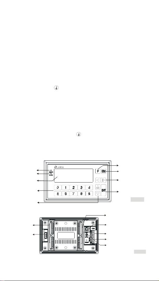
Front Panel
Pow er ind icator
Alarm indicator
Display area
Function/
Nemeric keys
Up/Down keys
Back Panel
Input/output
termin al blocks
Program copy
card interface
- 1 -
User-defined key
Escape/ Exit key
Left/Right keys
Enter key
Figure1
Input/outp ut
termi nal blocks
Program upload/download
commu nicat ion port (USB)
DC power supply
RS485 communication
Run/Stop switch
Figure2
Page 3
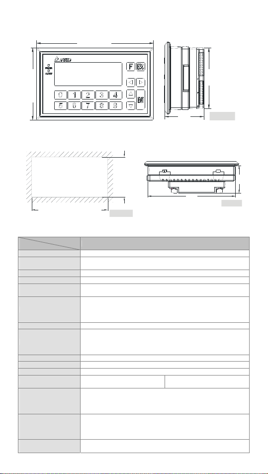
Front View and Right Side View (Units: mm, [ ]: inch)
175.8 [6.921]
]
6
7
2
.
4
[
6
.
8
0
1
59.2
[2.331]
Mounting Dimensions
Top View (Units: mm, [ ]: inch)
(Units: mm, [ ]: inch)
]
8
8
0
1
.
8
7
.
9
3
~
~
5
8
.
9
5
5
9
7
.
3
[
162.7~164.0 [6.4055~6.4567]
Thickness Range 0.5~5mm
Figure4
Function Specifications
Spec.
PLC program capa city 8k steps
Screen type/Display
color
Driver Delta automation products
Function/Numeric keys 0~9, ESC, F, Enter and Up/Down/Left/Right keys
Alarm LED indicator
(Red)
Backlight
Contrast adjustment Set by software, 10 levels of adjustment
Language/Font
Resolution 192 × 64 dots
Display range 101.8 mm (W) × 35.24 mm (H); 4.1” (diagonal)
Font size ASCII: 5 × 8, 8 × 8, 8 × 12, 8 × 16
Display text
Program
upload/download
communication port
USB (COM1)
Extension
communication port
RS485 (COM2)
RS485 (COM3)
Download & Monitoring
method
Model
STN-LCD/Monochromatic
Power indication (Blinking for three times)/Communication error
alarm/User program indication
Automatically turning off the backlight: 1~99 minutes (0: The
backlight is not turned off.)
(The life span of the backlight is about 50,000 hours at a
temperature of 25°C)
ASCII: (Code page 850) Alphanumeric code (including European
characters)
Taiwan: Traditional Chinese fonts
China: Simplified Chinese fonts
5×8 dots: 38 characters × 8 rows
8×8 dots: 24 characters × 8 rows
Transmission method: Virtual communication port
Data length: 7 or 8 bits, Stop bits: 1 or 2 bits, Parity: None/Odd/Even
Baud rate: 9,600 bps~115,200 bps
USB: USB (Type B) terminal
Asynchronous transmission method: RS-485
Data length: 7 or 8 bits, Stop bits: 1 or 2 bits, Parity: None/Odd/Even
Baud rate: 9,600 bps~115,200 bps
RS-485: 8 PIN-removable terminal block
Download program to TP through virtual COM port
- 2 -
TP04P series
8×12 dots: 24 characters × 5 rows
8×16 dots: 24 characters × 4 rows
162.2
[6.386]
91.73
[3.613]
Figure3
Figure5
51.2
[2.016]
Page 4
Spec.
Extension interface Slot for a program copy card
Panel components Description
Alarm LED indicator
(Red)
Power LED indicator
(Green)
Display area LCD module; it is used to display current program status.
Numeric keys
Function keys Users can define the keys.
Enter key (ENT)
Arrow keys
Model
Status 1: when turning on the power, this LED will start blinking
slowly and when the power is ON, this LED will be off.
Status 2: when the user-defined conditions are met, LED will blink
every 1 second along with an alarm sound.
When the power is ON, this LED will be ON.
Keys 0~9 can be used for inputting constants. Users can also define
the keys by themselves.
If the input value is correct, press the key to confirm the setting.
Users can def ine the key in the u ser page.
Up: for increasing the setting value or go to the previous page
Down: for decreasing the setting value or go the next page
Left/Right: for selecting the position of the setting value
Users can redefine functions of the arrow keys in the user page.
TP04P series
Electrical Specifications
Model
Spec.
CPU LPC1787FBD208
Program memory 1 MB-flash memory
RAM of the system 64K Bytes
Power supply voltage
Power consumption
Power protection With counter-connection protection on the polarity of DC input power
Insulation resistance > 5 MΩ (all I/O point-to-ground insulation resistance: 500 VDC)
Noise immunity
Ground
Operating temperature
for hardware
Storage temperat ure
for hardware
Waterproof class of the
front panel
Vibration/Shock
resistance
Weight 420g 444g
Dimensions 175.8 × 108.6 × 59.2 mm (Width(W) × Height(H) × Deep(D))
Cooling method Natural air cooling
Item
Input number X0, X1 X2~X7, X10~X17
Input type DC (Sinking or sourcing)
Input voltage (±10%) 24VDC, 5mA
Input impedance 4.7k ohm
Maximum frequency 10KHz 60Hz
Action level
Response
time
OffOn > 16.5 VDC
OnOff < 8 VDC
OffOn <20us
OnOff <50us
TP04P-
16TP1R/T
24VDC (-15% ~ 20%) (With counter-connection protection on the
polarity of DC input power)
3W / 2. 5W 5W / 4. 5W 4.7W / 4.5W 4.7W / 4.5W
ESD (IEC 61131-2, IEC 61000-4-2): 8KV Air Discharge
EFT (IEC 61131-2, IEC 61000-4-4): Power Line: 2KV, Digital I/O:
1KV, Analog & Communication I/O: 1KV
Damped-Oscillatory Wave: Power Line: 1KV, Digital I/O: 1KV
RS (IEC 61131-2, IEC 61000-4-3): 26MHz~1GHz, 10V/m
The diameter of ground cannot be less than the diameter of the
power cable. (If several TP04P are used, they should be grounded
directly.)
0°C~50°C: Relative humidity: 20%-90% RH (non-condensing)
-20°C~60°C
IP66/NEMA4
International standards IEC61131-2, IEC 68-2-6 (TEST Fc)/
IEC61131-2 & IEC 68-2-27 (TEST Ea)
Model
TP04P-
32TP1R/T
24VDC (-15% ~ 20%) single common terminal
TP04P-
22XA1R/T
432g 432g
Input terminal
- 3 -
10ms
TP04P-
21EX1R/T
Page 5
Item
#1
A
A
A
A
A
Voltage specifications 250VAC, < 30VDC 12-24VDC
Current
specifications
Response time
OffOn
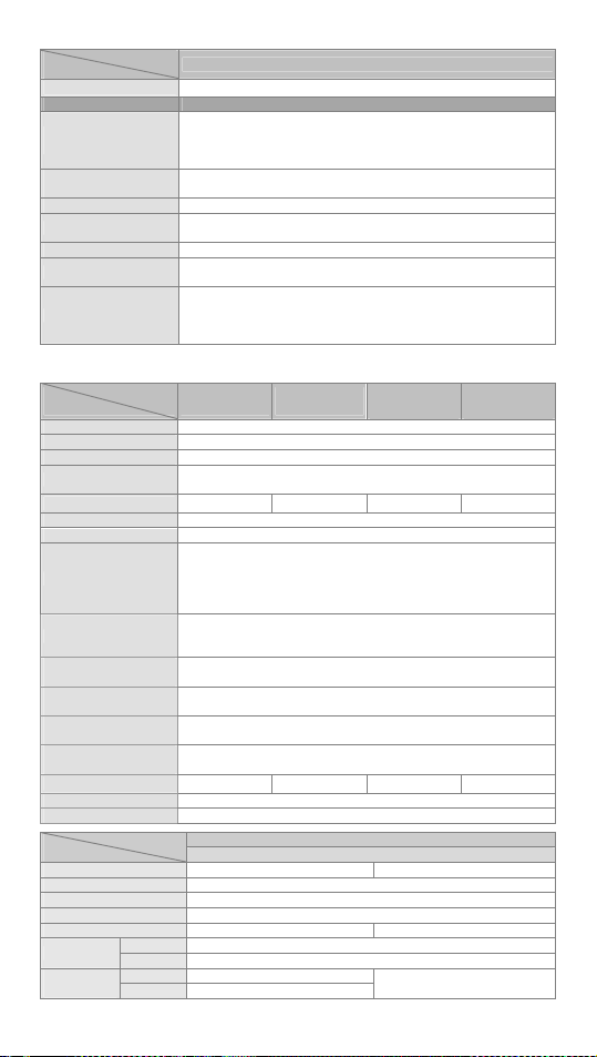
#1: Life curves
Item
Analog range ±10V ±20m
Digital conversion range ±2000 ±1000 ±2000 0~4000
Resolution
Input impedance 1MΩ 250Ω -- --
Output impedance -- -- 100Ω
Overall accuracy
Response time 3ms/Channel
Isolation None
Absolute Input range ±15V ±32m
Model
Resistive 1.5A /1 point (5A/COM) 1A /1 point (5A/COM)
Inductive
Bulb 20WDC/100WAC -
Approximately 10 ms Approximately 10 ms
120VAC Resistive
30VDC Inductive(t=7ms)
240VAC Inductive(cos 0.4)ψ=
30VDC
Inductiv e
50
(t=4 0ms)
30
20
0.1
0.2
0.5
0.3 0.7 1 2
Specifications for the analog input/output of TP04P-22XA1R/T
Voltage input Current input Voltage output Current output
12 bits
(1LSB=5mV)
25°C(77°F): The error is
0~55°C(32~131°F): The error is 1% of the input within the range
)
3
0
1
X
(
n
o
i
t
a
r
e
p
O
Model
3,000
2,000
1,000
500
300
200
100
Digital data format
Maximum current output
(Load allowed)
Protection
Item
Analog I/O range 0~20m
Digital conversion range 0~4000 0~4000
Resolution 12 bits(1LSB=5uA) 12 bits(1LSB=5uA)
Input impedance 250Ω --
Output impedance -- 100Ω
Response time 3ms/Channel
Absolute Input range 0~32m
Maximum current output
(Load allowed)
The voltage output is equipped with a short circuit protection and the
overcurrent protection. (If the voltage output is short-circuited for a
long time, it may be damaged.) The current output can be an open
circuit.
Model
Specifications for the analog input/output of TP04P-21EX1R/T
Current input Current output
Output terminal
Relay Transistor
Figure 6
-
120VAC Inductive(cos =0.4)
ψ
Contact
Current(A)
±10V 0~20mA
11 b it s
(1LSB=20uA)
12 bits
(1LSB=5mV)
(1LSB=5uA)
0.5% of the inp ut within the r ange
Two's complement of a 16-bit number
11 bits are significant bits.
--
-- --
10m
(1KΩ~2MΩ)
0~20mA
--
-- 0~500Ω
12 bits
0~500Ω
Specifications for temperature measurement
Sensor type 2-wire/3-wire Pt100
Driving current 1.6mA
Temperature input range -20°C~300°C
Digital conversion range -200~3000
Resolution 0.1°C
Overall accuracy
25°C(77°F): The error is
0~55°C(32~131°F): The error is 1% of the input within the range
0.5% of the inp ut within the r ange
Response time 300ms×Number of channels
Isolation None
- 4 -
Page 6
Model
Item
Digital data format
Specifications for the analog input/output of TP04P-21EX1R/T
Current input Current output
Two's complement of a 16-bit number
11 bits are significant bits.
Protection The current output can be an open circuit.
TP04P-32TP1R/T
(16DI/16DO)
S/S0
X0
X1
X2
X3
X4
X5
X6
X7
S/S1
X10
X11
X12
X13
X14
X15
X16
X17
C0
Y0
Y1
Y2
Y3
Y4
Y5
Y6
Y7
C1
Y10
Y11
Y12
Y13
Y14
Y15
Y16
Y17
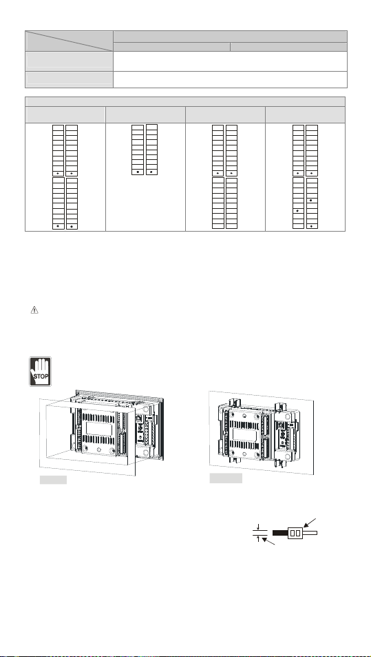
I/O Configuration (Figure7)
TP04P-16TP1R/T
(8DI/8DO)
S/S0
C0
Y0
X0
Y1
X1
Y2
X2
Y3
X3
Y4
X4
Y5
X5
Y6
X6
X7
Y7
TP04P-22XA1R/T
(8DI/8DO/4AI/2AO)
C0
S/S0
Y0
X0
Y1
X1
Y2
X2
Y3
X3
Y4
X4
Y5
X5
Y6
X6
X7
Y7
V0+
V3+
V3-
V0-
I3
I0
FE
V1+
V4
V1-
I4
I1
AG
V2+
V5
V2-
I5
I2
FE A G
TP04P-21EX1R/T
(8DI/8DO/2AI/1AO/2PT)
C0
S/S0
Y0
X0
Y1
X1
Y2
X2
Y3
X3
Y4
X4
Y5
X5
Y6
X6
X7
Y7
I0+
L3+
L3-
I0-
I3-
FE
FE
I1+
I1-
L4+
FE
L4I4-
I2
FE
AG
FE
Installation
Insert TP04P into the opening hole on the panel, and then tighten the screws. If it needs to be
mounted firmly, please use the mounting fixed supports and screws in the accessory package
which is packed with TP04P. Insert the hooks of the fixed supports into the fixing holes on the
back, and then tighten the screws. Please refer to figure 8 and figure 9 below for more
information.
The torque exerted on a screw should be 4.75 (kg-cm). Please tighten the screws
(
according to the specifications, otherwise the product may be damaged. If the fixed supports
are not installed well, Delta will not guarantee the waterproof rating.) The cover of the mounting
panel should be waterproof/dust proof or meet the related specifications (IP66/NEMA4).
Do not install TP04P in the following environment.
A location full of Airborne dust, metallic particles, oily smoke, corrosive or flammable
gases and liquids
High-temperature and humid environment
A location in which the product may be shocked and vibrated directly
Figure 8
Wiring
1. Please use single-core cables or twin-core cables. The
diameters of the cables used should be within the range
between 16 AWG and 22 AWG (1.5mm). The torque applied
to the screw terminals should be 1.90 kg-cm (1.65 in-lbs).
Please use copper conducting wires. The temperature of the
copper conducting wires should be 60/75°C.
2. DO NOT wire the empty terminal. DO NOT put the input signal cables and the output signal
cables in the same wiring.
3. DO NOT drop any tiny metallic conductor into TP04P while you are tightening screw and
wiring TP04P. After the wiring is complete, you have to ensure that heat can radiate from
TP04P.
Power Supply
The power input of TP04P is DC. When you operates TP04P, please note the following points:
Figure 9
22-16AWG
< 1.5mm
- 5 -
Page 7

1. The power is connected to two terminals, 24 VDC and 0 V, and the range of power is 20.4 to
28.8 VDC. If the power voltage is less than 20.4VDC, TP04P will stop running, all outputs will
be Off, and the ERROR indicator will start to blink.
2. If a power failure lasts for less than 10 ms, the operation of TP04P will not stop. However, if a
power failure lasts for long, or the power voltage decreases, TP04P will stop running, and all
outputs will be off. After the power returns to the normal status, TP04P will automatically
resume the operation. (Users have to note that TP04P is equipped with latched auxiliary
relays and registers when they write a program.)
Safety Wiring
Since TP04P is only compatible with DC power supply, Delta’s power supply modules
(DVPPS01/DVPPS02/DVPPS05) are suitable for it. İt is suggested that you shoudl install a
protection circuit at the power supply terminal to protect DVPPS01, DVPPS02, or DVPPS05.
See the figure below.
Sinking
2A
AC/DC
0V 24V
DVPPS01/DVPPS02/
DVPPS05
X1 X2S/S X0
Fig ure 11
2A
L
TP 04P
N
+24V
+24V
0V 0V
Breaker
AC power supply load
DVPPS01/DVPPS02/DVPPS05
TP04P
24VDC
Fi gu r e 1 0
Sourcing
X1 X2S/S X0+24V OV
Fig ure 12
AC
100- 240 V
50/6 0Hz
Guard
Limit
AC power supply:100 ~ 240VAC, 50/60Hz
Emergency stop: The emergency stop button can be used to cut off the power when an
emergency occurs.
Power indicator
Power supply circuit protection fuse (2A)
DC power supply output: 24VDC, 500mA
Wiring Input Terminals
There are 2 types of DC inputs. They are sinking inputs and souring inputs. (See the
figures below.)
Sinking mode Sourcing mode
+24V OV
24VDC
Wiring Relay Output Terminals (Sink)
- 6 -
Page 8

9
5 2
C0 C1Y0 Y4C2 Y2 Y3 Y 5Y1
3 7
8
MC2 MC1
2
5 4
10
1
MC2MC 1
7
11
[ Figu re 13 ]
*1: There is no internal protection circuit in the output relay of the PLC; therefore when activating
an inductive load, we suggest you parallel connect a reverse current protection diode to extend
the life of the c ontact.
6
11
DO NOT wire empt y
terminal
Fuse
Reverse current
protection diode*1
Manual exclusive
output*2
Emergency stop: by
external switch
Surge absorber*3
Inductive load
Indicator: incandescent
light
DC power supply
AC power supply
Resistive load
- The diode has to be able to endure max. 5 ~ 10 times of load voltage.
- The positive current of the diode has to be bigger than load current.
*2: Manual exclusive output uses external circuit and forms an interlock, together with the PLC
internal program, to ensure safety protection in case of any unexpected errors.
*3: There is no internal protection circuit in the output relay of the PLC; therefore when activating
an inductive load, we suggest you parallel connect a surge absorber (0.1uF + “100ohm to
120ohm”) to reduce the noise on AC load and extend the life of the contact.
Wiring Transistor Output Terminals (Sink)
Y4
C0 C1Y0
5 7 8
3
2
3
Y1
C2Y2Y3
MC2
6
*1: Manual exclusive output uses external circuit and forms an interlock, together with the PLC
internal program, to ensure safety protection in case of any unexpected errors.
*2: Use a Zener diode (39V) in the PLC to protect the transistor output. When activating
inductive load, we suggest you parallel connect a reverse current protection diode.
Wiring Analog I/O and Temperature Sensor
TP04P-22XA1R
Analog Input Analog Output
Volt age inp ut
-10V~+10V
Current input
-20mA~+20mA
Shiel ded
cable*1
Shiel ded
cable*1
CH0
*3
CH3
*2
Figu re 15
MC1
MC2MC1
4
V0+
I0
V0-
FE
V3+
I3
V3-
FE
Y5
6
9
[ Figu re 14 ]
AC motor d r iv e, reco rder,
p roport ioning va lve ...
AC motor dri ve, re corder ,
propo rtion in g val ve...
- 7 -
1
DO NOT wire empt y
terminal
Emergency stop
Fuse
Manual exclusive output*1
DC power supply
Indicator: incandescent light
Reverse current protection
diode*2
Inductive load
Resistive load
Voltag e output
-1 0V~ +10V
*3
Sh ielded
cable*1
Cur rent o utput
0mA~20 mA
Shielded
cable*1
CH4
CH5
Figure 16
V4
I4
AG
FE
V5
I5
AG
FE
Page 9

4
TP04P-21EX1R
Analog Input Analog Output
Current input
-20mA~+20mA
Shielded
cable*1
Pt100
2-wire
*1: The cables connected to the analog input terminals should be kept separate from other
power cables and cables which generate noise.
*2: If the text panel is connected to a current signal, the terminals V3+ and I3+ must be
short-circuited.
*3: If the ripple in the input voltage results in the noise interference with the wiring, please
connect the text panel to the capacitor having a capacitance in the range of 0.1 μF to 0.47 μF
with a working voltage of 25 V.
*4: Please connect the ground terminal on a power supply module and the analog input terminal
FE to the system ground, and then ground the system ground or connect the system ground
to a distribution box.
Shield ed cable*4
CH0
Figu re 17
I0+
I0-
FE
Pt100
L3+
L3-
I3-
FE
AC moto r drive, reco rder,
proporti oning valve...
Pt100
3-wire
Current ou tput
0mA~20mA
Shielded
cable*1
Shie lded cable *
CH2
Figur e 18
L4-
Figu re 19
I2
AG
FE
L4+
I4-
FE
RS-485 Wiring
1 2
D+ D- D+ D- D+ D-
3
Master station
Note: 1. The terminal resistor should be connected to the master station and the last slave
station. The resistance of the terminal resistor should be 120.
2. To ensure communication quality, it is suggested that users should use double shielded
twisted pair cables (20AWG) for wiring.
Slave station
2
3
Figure 20
Terminal resistor
Communication Connection
TP04P may connect to a PC by using USB adaptor cable.
Please use an AM/BM USB adaptor cable.
Figure 21
Battery’s Life
Temperature (°C) -20 0 20 60
Life (Year) 2.0 2.5 2.7 2.8
Precision of the Real Time Clock
(Second/Month)
Temperature (°C/°F) 0/32 25/77 55/131
Maximum error (Second) -117 52 -132
- 8 -
Page 10

……………………………………………………………… 繁體中文 …………………………………………………………………………
感謝您採用台達文本顯示器系列產品。TP04P 結合 PLC 與文本顯示器一體,具有豐富的指令集及
8k steps 的程式記憶體。TP04P 分別支援 PLC 編輯軟體(WPLSoft 及 ISPSoft)與 TP 編輯軟體
(TPEditor),可共用同一個下載埠;TPEditor 軟體規劃部份提供多種物件圖形供使用者選用。使
用者可另購程式擴充卡 TP-PCC01,快速移植程式,節省程式下載時間。請搭配台達 DVPPS01、
DVPPS02 及 DVPPS05(電源模組)一起使用。
請在使用之前,詳細閱讀本使用說明書。本安裝說明書提供給使用者電氣規格、功能規格、安
裝配線之相關注意事項。其他詳細之程式設計及指令說明請見 DVP-ES2/EX2/
SS2/SA2/SX2/SE&TP 操作手冊【程式篇】,選購之周邊裝置詳細說明請見該產品隨機安裝說
明書。
於實施配線前,請務必關閉電源。請勿在上電時觸摸任何端子。輸入電源切斷後,一分鐘之內,
請勿觸摸內部電路。請勿在上電時觸摸任何端子。
交流輸入電源不可連接於輸入⁄出信號端,否則可能造成嚴重損壞,請在上電之前再次確認電源
配線。
本體上之接地端子
本機顯示操作面板防水,但對油污或具腐蝕性之液體不具防護作用,避免以尖銳之物品刮傷面
板使用時請注意。
利用原廠包裝附件之固定架,鎖緊面板固定螺絲時,請勿太緊以免造成機殼損壞。
務必正確的接地,可提高產品抗雜訊能力。
產品外觀尺寸與部位介紹
正面圖(詳細正面圖請參閱英文版之Figure1)
背面圖(詳細背面圖請參閱英文版之Figure2)
正面及右側尺寸圖(單位:公厘,[ ]:英吋)(詳細尺寸圖請參閱英文版之Figure3)
嵌入開孔尺寸(單位:公厘,[ ]:英吋)(詳細尺寸圖請參閱英文版之Figure4)
俯視圖(單位:公厘,[ ]:英吋)(詳細尺寸圖請參閱英文版之Figure5)
功能規格
規格
PLC程式容量 8k steps
螢幕/色彩 STN-LCD / 單色
驅動器 台達產品
功能鍵/數字鍵 0 ~ 9,ESC,F,Enter及上/下/左/右鍵
警示指示燈(紅燈) 電源啟動指示(亮/滅三次)/通訊不通警示/使用者程式指定
背光型式
對比調整 軟體設定,10段明暗調整
語言字型 ASCII:(頁碼850)文字(包含歐洲字型、繁體字型及簡體字型)
解析度 192 × 64 點
顯示範圍 (寬)×(高)= 101.8 × 35.24(單位:公厘);4.1吋(對角線)
字型大小 ASCII:5 × 8,8 × 8,8 × 12,8 × 16
顯示的文字數
程式上下載通訊埠
USB(COM1)
擴充通訊埠
RS485(COM2)
RS485(COM3)
下載與監控方式 通過虛擬通訊埠下載至TP
機型
背光自動關閉設定範圍1 ~ 99分鐘(設定值0為不關閉)
(在常溫25℃下壽命約5萬小時)
5×8 畫素字型:38 個字 × 8 列
8×8 畫素字型:24 個字 × 8 列
傳送方式:虛擬通訊埠
資料長度:7或8 bits,停止位元:1或2 bits,極性:無/奇/偶
傳送速度:9,600bps ~ 115,200bps
USB:USB(Type B)端子
非同步傳送方式:RS-485
資料長度:7或8 bits,停止位元:1或2 bits,極性:無/奇/偶
傳送速度:9,600bps ~ 115,200bps
RS-485:8 PIN 脫落式端子
- 9 -
TP04P 系列
8×12 畫素字型:24 個字 × 5 列
8×16 畫素字型:24 個字 × 4 列
Page 11

規格
擴充介面 程式複製卡插槽
警示指示燈(紅燈)
電源指示燈(綠燈) 電源開啟時燈亮
顯示區 液晶顯示模組,顯示目前程式狀態。
數字鍵 0~9:可作為常數輸入鍵,也可由使用者定義其個別功能鍵。
F鍵 可供使用者定義
輸入鍵(ENT)
命令操作鍵
機型
面板元件 說明
狀態一:當啟動電源時,指示燈開始慢慢閃爍直到完全通電後指示燈滅。
狀態二:當符合使用者設定條件時,指示燈會重覆持續亮一秒並發出警
報聲。
當輸入值確認正確無誤時,即可按下此鍵;在使用者頁面時可由使用者
重新定義功能。
上:此鍵為向上方向鍵,可作為數值遞增輸入或換至上頁等操作。
下:此鍵為向下方向鍵,可作為數值遞減輸入或換至下頁等操作。
左:此鍵為左方向鍵,可作為選擇數值位置操作。
右:此鍵為右方向鍵,可作為選擇數值位置操作。
在使用者頁面時,可由使用者重新定義其個別功能。
TP04P 系列
電氣規格
機型
項目
中央處理單元(CPU) LPC1787FBD208
程式記憶體容量 1MB 快閃記憶體
系統RAM 64K Byte
電源電壓 24VDC(-15% ~ 20%)(具直流輸入電源極性反接保護)
消耗電力 3W / 2. 5W 5W / 4.5W 4 .7W / 4 .5W 4 .7W / 4 .5W
電源保護 具直流輸入電源極性反接保護
絕緣阻抗 > 5MΩ(所有輸出/入點對地之間500VDC)
雜訊免疫力
接地
硬體使用溫度 0°C ~ 50°C;相對濕度20% - 90% RH(不可凝結)
硬體儲藏溫度 -20°C ~ 60°C
前面板防水等級 IP66 / NEMA4
耐震動/衝擊
重量 420g 444g 432g 432g
外型尺寸 175.8 × 108.6 × 59.2 mm(寬(W)× 高(H)× 厚(D))
冷卻方式 空氣對流自然冷卻
項目
輸入點 X0, X1 X2~X7, X10~X17
輸入接線型式 由端子 S/S 變換接線為 SINK 或 SOURCE
TP04P-
16TP1R/T
ESD (IEC 61131-2, IEC 61000-4-2): 8KV Air Discharge
EFT (IEC 61131-2, IEC 61000-4-4): Power Line: 2KV, Digital I/O: 1KV,
Analog & Communication I/O: 1KV
Damped-Oscillatory Wave: Power Line: 1KV, Digital I/O: 1KV
RS (IEC 61131-2, IEC 61000-4-3): 26MHz ~ 1GHz, 10V/m
接地配線之線徑不得小於電源端配線線徑(多台TP04P同時使用時,請
務必單點接地)
國際標準規範 IEC61131-2, IEC 68-2-6 (TEST Fc) / IEC61131-2 &
IEC 68-2-27(TEST Ea)
機種
TP04P-
32TP1R/T
輸入點電氣規格
24VDC(-15% ~ 20%)單端共點輸入
- 10 -
TP04P-
22XA1R/T
TP04P-
21EX1R/T
Page 12

輸入信號電壓(±10%) 24VDC, 5mA
A
A
輸入點阻抗 4.7k Ohm
最大輸入頻率 10KHz 60Hz
動作位準
反應時間
項目
OffOn > 16.5 VDC
OnOff < 8 VDC
OffOn <20us
OnOff <50us
機種
繼電器 電晶體
10ms
輸出點電氣規格
電壓規格 250VAC, < 30VDC 12- 24VDC
電流規格
電阻性 1.5A /1 點(5A/COM) 1A /1 點( 5A/COM)
電感性
#1
-
燈泡 20WDC/100WAC -
反應時間
#1:生命週期曲線請參閱英文版之 Figure6。
項目
OffOn
OnOff
機種
約 10ms 約 10ms
TP04P-22XA1R/T 類比通道規格
電壓輸入 電流輸入 電壓輸出 電流輸出
類比範圍 ±10V ±20mA ±10V 0~20mA
數位轉換範圍 ±2000 ±1000 ±2000 0~4000
解析度
12 bits
(1LSB=5mV)
11 b it s
(1LSB=20uA)
12 bits
(1LSB=5mV)
12 bits
(1LSB=5uA)
輸入阻抗 1MΩ 250Ω -- -輸出阻抗 -- -- 100Ω
總和精密度
±0.5%在 25℃(77℉)範圍內滿刻度時;
±1%在 0~55℃(32~131℉)範圍內滿刻度時。
響應時間 3ms/通道
隔離方式 無隔離
絕對輸入範圍 ±15V ±32mA - - -數位資料格式 16 位元二補數,有效位 11 bit s
最大輸出電流
(容許負載)
保護 電壓輸出具短路保護(請勿長時間短路,有燒毀可能)電流輸出可開路
機種
項目
類比輸入範圍 0~20m
數位轉換範圍 0~4000 0~4000
解析度 12 bits(1LSB=5uA) 12 bits(1LSB=5uA)
--
TP04P-21EX1R/T 類比通道規格
電流輸入 電流輸出
10m
(1KΩ~2MΩ)
0~20mA
0~500Ω
輸入阻抗 250Ω -輸出阻抗 -- 100Ω
類比通道響應時間 3ms/通道
絕對輸入範圍 0~32mA --
最大輸出電流
(容許負載)
-- 0~500Ω
溫度量測規格
感應器型式 2線/3 線 Pt100
驅動電流 1.6mA
- 11 -
Page 13

機種
項目
輸入溫度範圍 -20℃~300℃
數位轉換範圍 -200~3000
解析度 0.1℃
總和精密度
溫度通道響應時間 300ms×通道
隔離方式 未隔離
數位資料格式 16 位元二補數,有效位 11 bit s
保護 電流輸出可開路
輸入/輸出配置
請參閱英文版之 Figure7
TP04P-21EX1R/T 類比通道規格
電流輸入 電流輸出
±0.5%在 25℃(77℉)範圍內滿刻度時;
±1%在 0~55℃(32~131℉)範圍內滿刻度時
安裝方式
TP04P 安裝於控制盤時,請直接將 TP 由盤面的正面直接放入即可(嵌入式)。若要固定更牢固,
可使用原廠包裝中所附的固定架含螺絲,直接嵌入後蓋四端凹槽處固定,並將螺絲平均鎖緊即可
固定螺絲時請以扭力:4.75(kg-cm)鎖緊,請勿超過此範圍以免破壞面板;如未正確使用
(
固定架,台達不保證防水等級。),詳細圖面請參閱英文版 Figure8 與 Figure9。該安裝的配電盤
外殼必須符合防水防塵或符合相等規格(IP66/NEMA4)的測試條件。
請勿將 TP04P 裝置於以下環境中:
落塵大、油煙、金屬性粉塵、腐蝕性或可燃性氣體
高溫、結露
直接震動、衝擊
配線端子
1. 輸出/入配線端請使用 22-16AWG(1.5mm)單蕊祼線或
多蕊線端子規格如右圖所示。TP04P 端子螺絲扭力為 1.90
kg-cm(1.65 in-lbs)。只能使用 60/75°C 的銅導線。
2. 空端子請勿配線。輸入點信號線與輸出點等動力線請勿置於同一線槽內。
3. 鎖螺絲及配線時請避免微小的金屬導體掉入 TP04P 內部,並在配線完成後保持散熱空間。
電源端
TP04P 機種為直流電源輸入,在使用上應注意下列事項:
1. 電源請接於 24VDC 及 0V 兩端,電源範圍為 20.4 ~ 28.8VDC,當電源電壓低於 20.4VDC 時,
TP04P 會停止運轉,輸出全部 Off,ERROR LED 快速閃爍。
2. 當停電時間低於 10ms 時,TP04P 不受影響繼續運轉,當停電時間過長或電源電壓下降將使
TP04P 停止運轉,輸出全部 Off,當電源恢復正常時,TP04P 亦自動回復運轉。(TP04P 內部
具停電保持的輔助繼電器及暫存器,使用者在規劃程式設計時應特別注意使用。)
安全配線回路
由於 TP04P 的電源為 DC Only 的機種,因此可搭配台達之電源供應模組(DVPPS01/
DVPPS02/DVPPS05)提供電源給 TP04P。為保護 DVPPS01/ DVPPS02/DVPPS05,建議可在
電源的輸入回路端配置如下的保護回路,配置圖請參閱英文版之 Figure 10 所示。
交流電源供應:100 ~ 240VAC, 50/60Hz 斷路器
緊急停止:為預防突發狀況發生,設置緊急停止按鈕,可在狀況發生時,切斷系統電源。
電源指示燈 交流電源負載
電源回路保護用保險絲(2A) DVPPS01/DVPPS02/DVPPS05 本體
直流電源供應輸出:24VDC,500mA TP04P 本體
輸入點之配線
輸入點之入力信號為直流電源 DC 輸入型式,共有兩種接法:SINK 及 SOURCE,其定義與輸入
點回路等效電路配線圖,請參閱英文版之 Figure 11 及 Figure 12。
- 12 -
22-16AWG
< 1.5mm
Page 14

繼電器輸出回路配線(Sink)
詳細配線圖請參閱英文版之 Figure13。
1
○
空端子請勿配線 ○2保險絲
○3 反向電流保護二極體:在PLC 的輸出繼電器並沒有內部保護電路,因此若使用在直流電感性
負載時,請並聯接上一個反向電流保護二極體,可增加接點壽命。反向電流保護二極體須符
合下列規格:必須能承受最大 5 ~ 10 倍的負載電壓及正向電流須大於負載電流。
○4 互斥輸出:利用外部電路形成互鎖,配合 PLC 內部程式,確保任何異常突發狀況發生時,均
有安全的保護措施。
○5 緊急停止:使用外部開關 ○
○6 突波吸收器:在 PLC 的輸出繼電器並沒有內部保護電路,因此若使用在交流電感性負載時,
請並聯接上一個突波吸收器 (0.1uF + “100ohm to 120ohm”) 可減少交流負載上的雜訊,
可增加接點壽命。
○8 指示燈:氖燈 ○
9
直流電源供給 ○10交流電源供給
7
電感性負載
11
電阻性負載
電晶體輸出回路配線(Sink)
詳細配線圖請參閱英文版之 Figure14。
1
○
空端子請勿配線 ○
○4 互斥輸出:利用外部電路形成互鎖,配合 PLC 內部程式,確保任何異常突發狀況發生時,均
有安全的保護措施。
2
緊急停止:使用外部開關 ○
3
保險絲
○5 直流電源供給 ○6 指示燈:氖燈
○7 反向電流保護二極體:在 PLC 的輸出繼電器並沒有內部保護電路,因此若使用在直流電感性
負載時,請並聯接上一個反向電流保護二極體,可增加接點壽命。反向電流保護二極體須符
合下列規格:必須能承受最大 5 ~ 10 倍的負載電壓及正向電流須大於負載電流。
○8 電感性負載 ○
9
電阻性負載
類比/温度配線
詳細配線圖請參閱英文版之 Figure15 ~ Figure19。
註 1:類比輸入請與其它電源隔離
註 2:如果連接電流訊號時,V3+與 I3+端子請務必短路。
註 3:如果輸入電壓有漣波造成配線受雜訊干擾時,請連接 0.1~0.47uF 25V 之電容。
註 4:請將電源模組的接地端子及類比輸入端之 FE 連接到系統接地點,再將系統接地點作第三種
接地或接到配電箱之機殼上。
RS-485 建議接線
詳細接線圖請參閱英文版之 Figure 20。
主站 從站 終端電阻
附註:1. 終端電阻建議連接於主站及最後一台從站上,且其電阻值建議為 120。
2. 為確保連線品質,線材建議使用具有雙層遮蔽線之通訊雙絞線(20AWG)。
通訊連接線配線圖
TP04P程式規劃 - 使用USB
請使用 USB A 公轉 B 公之連接電纜線,詳細圖面請參閱英文版之 Figure 21。
電池壽命
溫度(°C) -20 0 20 60
壽命(年) 2.0 2.5 2.7 2.8
萬年曆的精度(秒/月)
溫度(°C/°F) 0/32 25/77 55/131
最大誤差(秒) -117 52 -132
- 13 -
Page 15

……………………………………………………………… 简体中文 …………………………………………………………………………
感谢您采用台达文本显示器系列产品。TP04P 结合 PLC 与文本显示器一体,具有丰富的
指令集及 8k steps 的程序内存。TP04P 分别支持 PLC 编辑软件
TP 编辑软件(TPEditor),可共享同一个下载埠;TPEditor 软件规划部份提供多种对象图
形供使用者选用。使用者可另购程序扩充卡
间。请搭配台达 DVPPS01、DVPPS02 及 DVPPS05(电源模块)一起使用。
请在使用之前,详细阅读本使用说明书。本安装说明书提供给使用者电气规格、功能
规格、安装配线之相关注意事项。其它详细之程序设计及指令说明请见
DVP-ES2/EX2/SS2/SA2/SX2/SE&TP 操作手册【程序篇】,选购之周边装置详细说明
请见该产品随机安装说明书。
请在使用之前,详细阅读本使用说明书。于实施配线前,请务必关闭电源。请勿在上
电时触摸任何端子。输入电源切断后,一分钟之内,请勿触摸内部电路。请勿在上电
时触摸任何端子。
交流输入电源不可连接于输入⁄出信号端,否则可能造成严重损坏,请在上电之前再次
确认电源配线。
本体上之接地端子
本机显示操作面板防水,但对油污或具腐蚀性之液体不具防护作用,避免以尖锐之物
品刮伤面板使用时请注意。
利用原厂包装附件之固定架,锁紧面板固定螺丝时,请勿太紧以免造成机壳损坏。
务必正确的接地,可提高产品抗噪声能力。
TP-PCC01,快速移植程序,节省程序下载时
(WPLSoft 及 ISPSoft)与
产品外观尺寸与部位介绍
正面图(详细正面图请参阅英文版之Figure1)
背面图(详细背面图请参阅英文版之Figure2)
正面图及右侧图(单位:公厘,[ ]:英吋)(详细尺寸图请参阅英文版之Figure3)
嵌入开孔尺寸(单位:公厘,[ ]:英吋)(详细尺寸图请参阅英文版之Figure4)
俯视图(单位:公厘,[ ]:英吋)(详细尺寸图请参阅英文版之Figure5)
功能规格
规格
PLC程序容量 8k steps
屏幕/色彩 STN-LCD / 单色
驱动器 台达产品
功能键/数字键 0 ~ 9,ESC,F,Enter及上/下/左/右键
警示指示灯(红灯) 电源启动指示(亮/灭三次)/通讯不通警示/使用者程序指定
背光型式
对比调整 软件设定,10段明暗调整
语言字型 ASCII:(页码850)文字(包含欧洲字型、繁体字型及简体字型)
分辨率 192 × 64 点
显示范围 (宽)×(高)= 101.8 × 35.24(单位:毫米);4.1吋(对角线)
字号 ASCII:5 × 8,8 × 8,8 × 12,8 × 16
显示的文字数
程序上下载通讯端口
USB(COM1)
扩充通讯端口
RS485(COM2)
机型
背光自动关闭设定范围1 ~ 99分钟(设定值0为不关闭)
(在常温25℃下寿命约5万小时)
5×8 画素字型:38 个字 × 8 列
8×8 画素字型:24 个字 × 8 列
传送方式:虚拟通讯端口
数据长度:7或8 bits,停止位:1或2 bits,极性:无/奇/偶
传送速度:9,600bps ~ 115,200bps
USB:USB(Type B)端子
异步传送方式:RS-485
数据长度:7或8 bits,停止位:1或2 bits,极性:无/奇/偶
- 14 -
TP04P 系列
8×12 画素字型:24 个字 × 5 列
8×16 画素字型:24 个字 × 4 列
Page 16

规格
RS485(COM3) 传送速度:9,600bps ~ 115,200bps
下载与监控方式 通过虚拟通讯端口下载至TP
扩充接口 程序复制卡插槽
警示指示灯(红灯)
电源指示灯(绿灯) 电源开启时灯亮
显示区 液晶显示模块,显示目前程序状态。
数字键 0~9:可作为常数输入键,也可由用户定义其个别功能键。
F键 可供使用者定义
输入键(ENT)
命令操作键
机型
RS-485:8 PIN 脱落式端子
面板组件 说明
状态一:当启动电源时,指示灯开始慢慢闪烁直到完全通电后指示灯灭。
状态二:当符合使用者设定条件时,指示灯会重复持续亮一秒并发出警
报声。
当输入值确认正确无误时,即可按下此键;在用户页面时可由用户重新
定义功能。
上:此键为向上箭头键,可作为数值递增输入或换至上页等操作。
下:此键为向下箭头键,可作为数值递减输入或换至下页等操作。
左:此键为左箭头键,可作为选择数值位置操作。
右:此键为右箭头键,可作为选择数值位置操作。
在使用者页面时,可由用户重新定义其个别功能。
TP04P 系列
电气规格
机型
TP04P-
项目
中央处理单元(CPU)
程序内存容量 1MB 闪存
系统RAM
电源电压 24VDC(-15% ~ 20%)(具直流输入电源极性反接保护)
消耗电力
电源保护 具直流输入电源极性反接保护
绝缘阻抗 > 5MΩ(所有输出/入点对地之间500VDC)
噪声免疫力
接地
硬件使用温度 0°C ~ 50°C;相对湿度20% - 90% RH(不可凝结)
硬件储藏温度
前面板防水等级
耐震动/冲击
重量
外型尺寸 175.8 × 108.6 × 59.2 mm(宽(W)× 高(H)× 厚(D))
冷却方式 空气对流自然冷却
16TP1R/T
LPC1787FBD208
64K Byte
3W / 2. 5W 5W / 4. 5W 4.7W / 4.5W 4 .7W / 4 .5W
ESD (IEC 61131-2, IEC 61000-4-2): 8KV Air Discharge
EFT (IEC 61131-2, IEC 61000-4-4): Power Line: 2KV, Digital I/O: 1KV,
Analog & Communication I/O: 1KV
Damped-Oscillatory Wave: Power Line: 1KV, Digital I/O: 1KV
RS (IEC 61131-2, IEC 61000-4-3): 26MHz ~ 1GHz, 10V/m
接地配线之线径不得小于电源端配线线径(多台TP04P同时使用时,请
务必单点接地)
-20°C ~ 60°C
IP66 / NEMA4
国际标准规范 IEC61131-2, IEC 68-2-6(TEST Fc)/ IEC61131-2 & IEC
68-2-27(TEST Ea)
420g 444g
TP04P-
32TP1R/T
- 15 -
TP04P-
22XA1R/T
432g 432g
TP04P-
21EX1R/T
Page 17

机种
A
项目
输入点
X0, X1 X2~X7, X10~X17
输入点电气规格
24VDC(-15% ~ 20%)单端共点输入
输入接线型式 由端子 S/S 变换接线为 SINK 或 SOURCE
24VDC, 5mA
4.7k Ohm
10ms
输出点电气规格
-
输入信号电压(±10%)
输入点阻抗
最大输入频率
动作位准
反应时间
OffOn > 16.5 VDC
OnOff < 8 VDC
OffOn <20us
OnOff <50us
机种
项目
电压规格
电阻性 1.5A /1 点(5A/COM) 1A /1 点( 5A/COM)
电流规格
电感性
灯泡
10KHz 60Hz
继电器 電晶體
250VAC, < 30VDC 12-24VDC
#1
20WDC/100WAC -
反应时间 约 10ms 约 10ms
#1:生命周期曲线请参阅英文版之 Figure6。
项目
机种
电压输入 电流输入 电压输出 电流输出
TP04P-22XA1R/T 模拟量通道规格
输入输出范围 ±10V ± 20mA ±10V 0~20mA
数字转换范围 ±2000 ±1000 ±2000 0~4000
分辨率
12 bits
(1LSB=5mV)
11 b it s
(1LSB=20uA)
12 bits
(1LSB=5mV)
12 bits
(1LSB=5uA)
输入阻抗 1MΩ 250Ω -- --
输出阻抗 -- -- 100Ω
总和精密度
±0.5%在 25℃(77℉)范围内满刻度时;
±1%在 0~55℃(32~131℉)范围内满刻度时。
响应时间 3ms/通道
隔离方式 无隔离
绝对输入范围 ±15V ± 32mA -- -数字数据格式 16 位二补码,有效位 11 bits
最大输出电流
(容许负载)
--
10m
(1KΩ~2MΩ)
0~500Ω
保护 电压输出具短路保护(请勿长时间短路,有烧毁可能)电流输出可开路
项目
机种
TP04P-21EX1R/T 模拟量通道规格
电流输入 电流输出
输入输出范围 0~20mA 0~20mA
数字转换范围 0~4000 0~4000
分辨率 12 bits(1LSB=5uA) 12 bits(1LSB=5uA)
输入阻抗 250Ω --
输出阻抗 -- 100Ω
响应时间 3ms/通道
绝对输入范围 0~32mA --
- 16 -
Page 18

机种
项目
最大输出电流
(容许负载)
温度量测规格
感应器型式 2线/3 线 Pt100
驱动电流 1.6mA
输入温度范围 -20℃~300℃
数字转换范围 -200~3000
分辨率 0.1℃
总和精密度
响应时间 300ms×通道
隔离方式 未隔离
数字数据格式 16 位二补码,有效位 11 bits
保护 电流输出可开路
TP04P-21EX1R/T 模拟量通道规格
电流输入 电流输出
-- 0~500Ω
±0.5%在 25℃(77℉)范围内满刻度时;
±1%在 0~55℃(32~131℉)范围内满刻度时。
输入/输出配置
详细配线图请参阅英文版之 Figure7。
安装方式
TP04P 安装于控制盘时,请直接将 TP 由盘面的正面直接放入即可(嵌入式)。若要固定更牢固,
可使用原厂包装中所附的固定架含螺丝,直接嵌入后盖四端凹槽处固定,并将螺丝平均锁紧即可
固定螺丝时请以扭力:4.75(kg-cm)锁紧,请勿超过此范围以免破坏面板;如未正确使用
(
固定架,台达不保证防水等级。),详细图面请参阅英文版 Figure8 与 Figure9。该安装的配电盘
外壳必须符合防水防尘或符合相等规格(IP66/NEMA4)的测试条件。
请勿将 TP04P 装置于以下环境中:
落尘大、油烟、金属性粉尘、腐蚀性或可燃性气体
高温、结露
直接震动、冲击
配线端子
1. 输出/入配线端请使用 22-16AWG(1.5mm)单蕊祼线或
多蕊线端子规格如右图所示。TP04P 端子螺丝扭力为 1.90
kg-cm(1.65 in-lbs)。只能使用 60/75°C 的铜导线。
2. 空端子请勿配线。输入点信号线与输出点等动力线请勿置于同一线槽内。
3. 锁螺丝及配线时请避免微小的金属导体掉入TP04P 内部,并在配线完成后保持散热空间。
电源端
TP04P 机种为直流电源输入,在使用上应注意下列事项:
1. 电源请接于 24VDC 及 0V 两端,电源范围为 20.4 ~ 28.8VDC,当电源电压低于 20.4VDC 时,
TP04P 会停止运转,输出全部 Off,ERROR LED 快速闪烁。
2. 当停电时间低于 10ms 时,TP04P 不受影响继续运转,当停电时间过长或电源电压下降将使
TP04P 停止运转,输出全部 Off,当电源恢复正常时,TP04P 亦自动回复运转。(TP04P 内部
具停电保持的辅助继电器及缓存器,使用者在规划程序设计时应特别注意使用。)
22-16AWG
< 1.5mm
- 17 -
Page 19

安全配线回路
由于 TP04P 的电源为 DC Only 的机种,因此可搭配台达之电源供应模块(DVPPS01/
DVPPS02/DVPPS05)提供电源给 TP04P。为保护 DVPPS01/ DVPPS02/DVPPS05,建议可在
电源的输入回路端配置如下的保护回路,配置图请参阅英文版之 Figure 10 所示。
交流电源供应:100 ~ 240VAC, 50/60Hz
紧急停止:为预防突发状况发生,设置紧急停止按钮,可在状况发生时,切断系统电源。
电源指示灯
电源回路保护用保险丝(2A)
直流电源供应输出:24VDC,500mA
断路器
交流电源负载
DVPPS01/DVPPS02/DVPPS05 本体
TP04P 本体
输入点之配线
输入点之入力信号为直流电源 DC 输入型式,共有两种接法:SINK 及 SOURCE,其定义与输入
点回路等效电路配线图,请参阅英文版之 Figure 11 及 Figure 12。
继电器输出回路配线(Sink)
详细配线图请参阅英文版之 Figure13。
1
○
空端子请勿配线 ○2保险丝
○3 反向电流保护二极管:在 PLC 的输出继电器并没有内部保护电路,因此若使用在直流电感
性负载时,请并联接上一个反向电流保护二极管,可增加接点寿命。反向电流保护二极管
须符合下列规格:必须能承受最大 5 ~ 10 倍的负载电压及正向电流须大于负载电流。
○4 互斥输出:利用外部电路形成互锁,配合 PLC 内部程序,确保任何异常突发状况发生时,
均有安全的保护措施。
○5 紧急停止:使用外部开关 ○
○6 突波吸收器:在 PLC 的输出继电器并没有内部保护电路,因此若使用在交流电感性负载时,
请并联接上一个突波吸收器 (0.1uF + “100ohm to 120ohm”) 可减少交流负载上的噪声,可
增加接点寿命。
○8 指示灯:氖灯 ○
9
直流电源供给 ○10 交流电源供给 11 电阻性负载
7
电感性负载
晶体管输出回路配线(Sink)
详细配线图请参阅英文版之 Figure14。
1
○
空端子请勿配线 ○
○4 互斥输出:利用外部电路形成互锁,配合 PLC 内部程序,确保任何异常突发状况发生时,
均有安全的保护措施。
2
紧急停止:使用外部开关 ○
3
保险丝
○5 直流电源供给 ○6 指示灯:氖灯
○7 反向电流保护二极管:在PLC 的输出继电器并没有内部保护电路,因此若使用在直流电感
性负载时,请并联接上一个反向电流保护二极管,可增加接点寿命。反向电流保护二极管
须符合下列规格:必须能承受最大 5 ~ 10 倍的负载电压及正向电流须大于负载电流。
○8 电感性负载 ○
9
电阻性负载
模拟/温度配线
详细配线图请参阅英文版之 Figure15 ~ Figure19。
注 1:模拟输入请与其它电源隔离
注 2:如果连接电流讯号时,V3+与 I3+端子请务必短路。
注 3:如果输入电压有涟波造成配线受噪声干扰时,请连接 0.1~0.47uF 25V 之电容。
注 4:请将电源模块的接地端子及模拟输入端之 FE 连接到系统接地点,再将系统接地点作第三种
接地或接到配电箱之机壳上。
RS-485 建议接线
详细接线图请参阅英文版之 Figure 20。
主站
附注:1. 终端电阻建议连接于主站及最后一台从站上,且其电阻值建议为 120。
2. 为确保联机质量,线材建议使用具有双层遮蔽线之通讯双绞线(20AWG)。
从站
- 18 -
终端电阻
Page 20

通讯连接线配线图
TP04P程序规划 - 使用USB
请使用USB A公转B公之连接电缆线,详细图面请参阅英文版之Figure 21。
电池寿命
温度(°C)
寿命(年)
-20 0 20 60
2.0 2.5 2.7 2.8
万年历的精度(秒/月)
温度(°C/°F)
最大误差(秒)
0/32 25/77 55/131
-117 52 -132
- 19 -
 Loading...