

Delta Tesla T3552LF-WL, Compel T3561LF-WL Series Installation Manuals
85865
F
L
Model/Modelo/Modèle
T3552LF-WL
Series/Series/Seria
TM
Tesla
Write purchased model number here.
Escriba aquí el número del modelo comprado.
Inscrivez le numéro de modèle ici.
Rough-in R3500-WL required for installation
Rough-in R3500-WL necesario para la instalación
Rough-in R3500-WL requis pour l'installation
You may need / Usted puede necesitar / Articles dont vous pouvez avoir besoin:
O
E
T
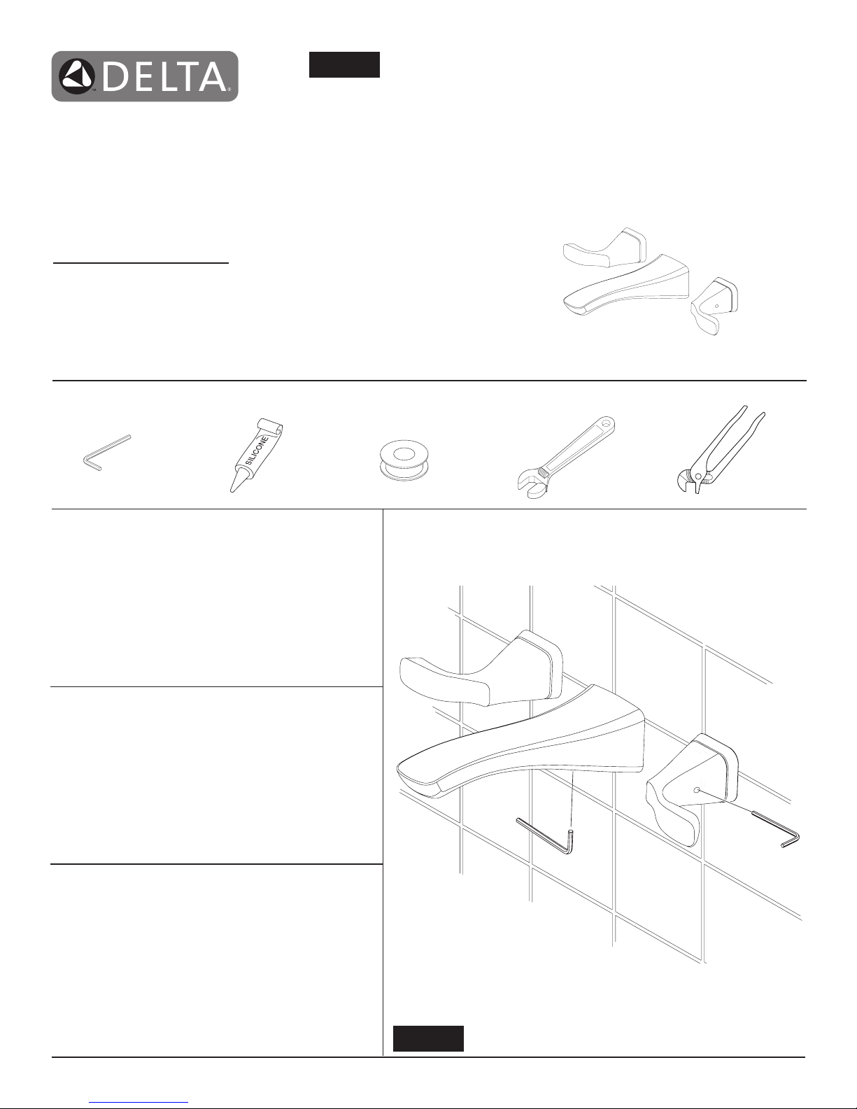
TWO HANDLE WALL MOUNTED LAVATORY
FAUCET TRIM
LLAVES DE AGUA - GRIFOS - DE DOS MANIJAS
PARA INSTALACIÓN EN LA PARED
ROBINETS MURAUX À DEUX MANETTES POUR
LAVABOMURAL POUR LAVABOS
N
1/8" (3.17mm)
For easy installation of your Delta faucet
you will need:
To
READ ALL
・
beginning.
To
READ ALL
・
information.
To complete the deck and valve rough-in prior to
・
installing this trim kit.
the instructions completely before
warnings, care and maintenance
Para instalación fácil de su llave Delta
usted necesitará:
LEER TODAS
・
antes de empezar.
LEER TODAS
・
de mantenimiento.
Para completar el borde y la instalación de válvulas
・
dentro de las paredes previa a la instalación de la
llave y sus accesorios.
las instrucciones completamente
los avisos, cuidados, e información
Pour installer votre robinet Delta
facilement, vous devez:
1/8" (3.17mm) 1/8" (3.17mm)
LIRE TOUTES
・
LIRE TOUE LES
・
les instructions de nettoyage et d’entretien.
Installez le corps du robinet et terminez le
・
pourtour du bain avant de poser les accessories
de nition.
www.deltafaucet.com
les instructions avant de débuter.
les avertissements ainsi que toutes
85865
1
4/26/2016 Rev. C
A.
1 2
1
B.
2
Figure 1
1
3
4
2
4
3
2
1
3
1
C.
1
2
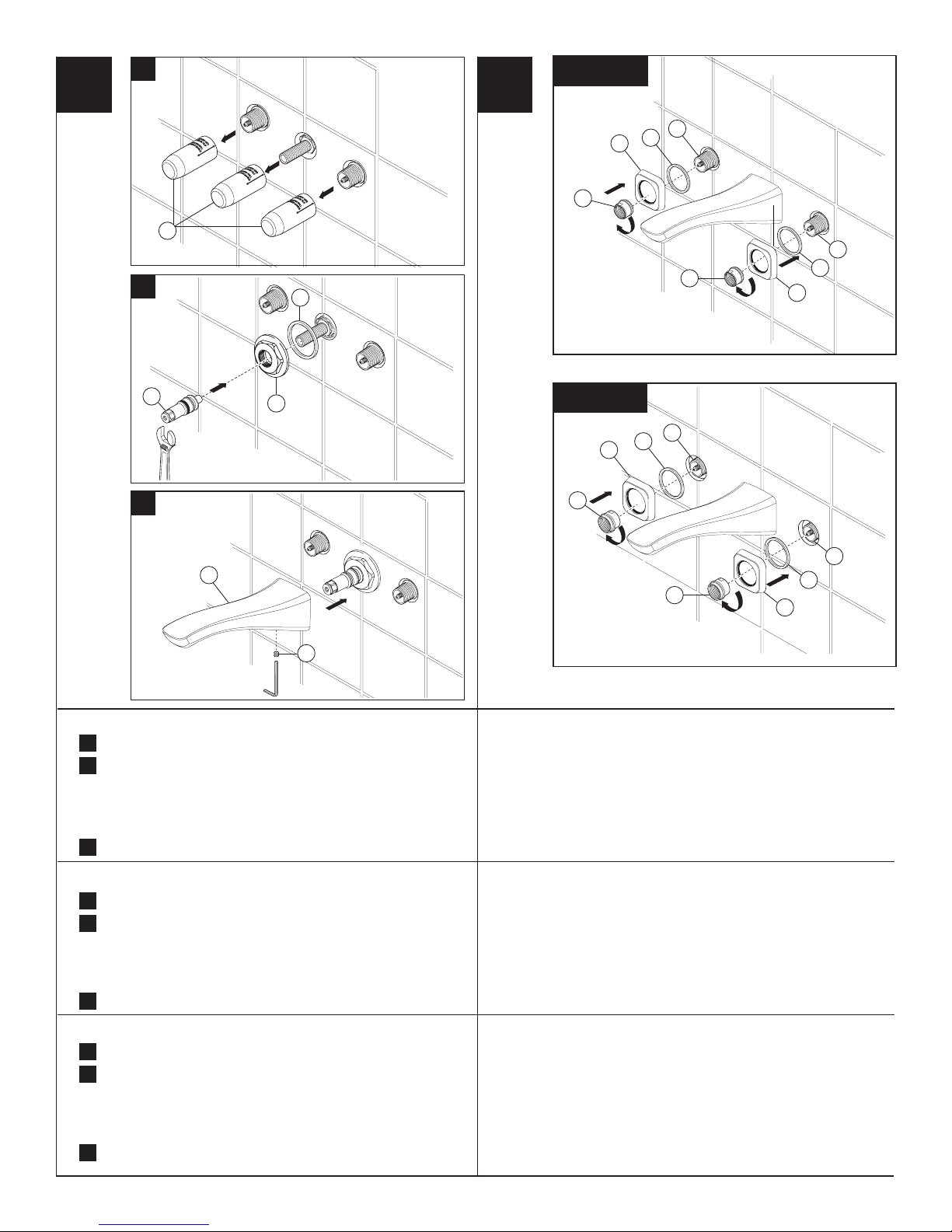
SPOUT FLANGE AND SPOUT INSTALLATION HANDLE FLANGE INSTALLATION
Pull off plasterguards (1) and discard them.
A
.
Install spout ange (1) and gasket (2). Option: If mounting
B
.
surface is uneven, apply suitable sealant to the back surface of
each escutcheon, according to the manufacturer’s instructions.
Finished wall thickness can vary from 1/8" to 1 1/8". Install spout
tube adapter (3). Tighten until adapter bottoms out on nut.
Install spout (1) and secure with set screw (2).
C
.
INSTALACIÓN DEL ADAPTADOR DEL SURTIDOR
Pull off plasterguards (1) and discard them.
A
.
Install spout ange (1) and gasket (2). Option: If mounting
B
.
surface is uneven, apply suitable sealant to the back surface of
each escutcheon, according to the manufacturer’s instructions.
Finished wall thickness can vary from 1/8" to 1 1/8". Install spout
tube adapter (3). Tighten until adapter bottoms out on nut.
Install spout (1) and secure with set screw (2).
C
.
Install handle ange (1) and gasket (2). Secure with ange nut (3).
Finished wall thickness can vary from 1/8 "to 1 1/8". If mounting sleeve
(4) is extending from nished wall more than 3/8", install ange nut (3)
as shown in gure 1. If mounting sleeve (4) is sub ush or extending less
than 3/8" from nished wall, install ange nut (3) as shown in gure 2.
HANDLE FLANGE INSTALLATION
Instale el reborde de la manija (1) y el empaque (2). Fije con la tuerca
con la arandela incorporada (3). El espesor de la pared acabada puede
variar desde 1/8" hasta 1 1/8". Si la mang a de instalación manga (4)
sobrepasa más de 3/8" de la pared acabada, instale la tuerca con la
arandela incorporada (3) como se muestra en el diagrama 1. Si la mang
a de instalación manga (4) está por debajo del nivel de la pared o se
extiende menos de 3/8" de la pared acabada, instale la tuerca con la
arandela incorporada (3) como se muestra en el diagrama 2.
Figure 2
1
3
4
2
3
4
2
1
SPOUT FLANGE AND SPOUT INSTALLATION
Pull off plasterguards (1) and discard them.
A
.
Install spout ange (1) and gasket (2). Option: If mounting
B
.
surface is uneven, apply suitable sealant to the back surface of
each escutcheon, according to the manufacturer’s instructions.
Finished wall thickness can vary from 1/8" to 1 1/8". Install spout
tube adapter (3). Tighten until adapter bottoms out on nut.
Install spout (1) and secure with set screw (2).
C
.
HANDLE FLANGE INSTALLATION
Installez l’embase de la manette (1) et le joint (2). Fixez la manette avec
l’écrou à embase (3). L’épaisseur du mur ni peut varier de 1/8" à 1
1/8" . Si la saillie du manchon (4) par rapport à la surface du mur ni est
supérieure à 3/8 po, installez l’écrou à embase (3) comme le montre la
gure 1. Si le manchon (4) est en retrait par rapport à la surface du mur
ni ou s’il présente une saillie de moins de 3/8 po par rapport à celle-ci,
installez l’écrou à embase (3) comme le montre la gure 2.
2
85865 Rev. C
 Loading...