

Page 1
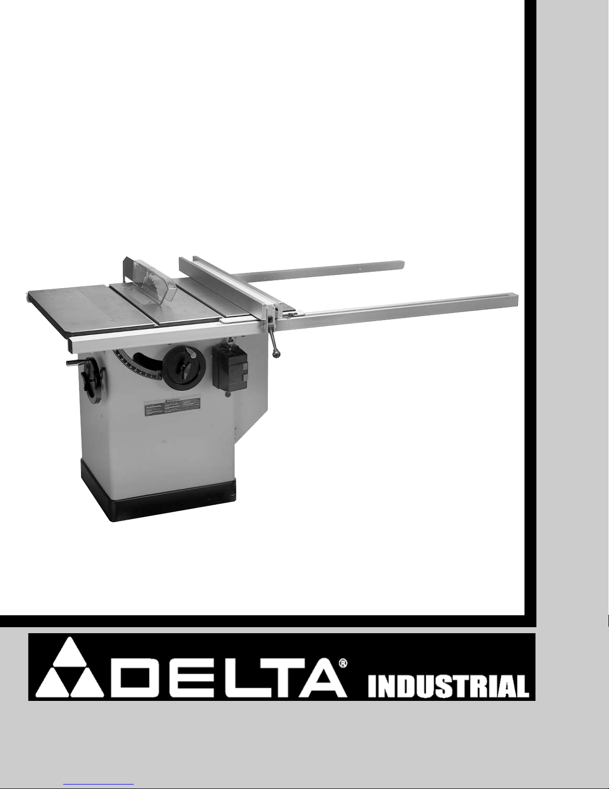
SHOWN WITH MODEL
36-729 CABINET SAW
INSTRUCTIONS
T
²
Fence System
T²-30 (30" Capacity Fence System)
T²-50 (50" Capacity Fence System)
PART NO. 911978 - 04-29-05
Copyright © 2005 Delta Machinery
To learn more about DELTA MACHINERY
visit our website at: www.deltamachinery.com.
For Parts, Service, Warranty or other Assistance,
please call
1-800-223-7278 (In Canada call 1-800-463-3582).
Page 2

2
TABLE OF CONTENTS
Read and understand all warnings and operating instructions before using any tool or equipment. When
using tools or equipment, basic safety precautions should always be followed to reduce the risk of personal injury.
Improper operation, maintenance or modification of tools or equipment could result in serious injury and property
damage. There are certain applications for which tools and equipment are designed. Delta Machinery strongly
recommends that this product NOT be modified and/or used for any application other than for which it was designed.
If you have any questions relative to its application DO NOT use the product until you have written Delta Machinery
and we have advised you.
Online contact form at www
.deltamachinery.com
Postal Mail: Technical Service Manager
Delta Machinery
4825 Highway 45 North
Jackson, TN 38305
(IN CANADA: 125 Mural St. Suite 300, Richmond Hill, ON, L4B 1M4)
Information regarding the safe and proper operation of this tool is available from the following sources:
Power Tool Institute
1300 Sumner Avenue, Cleveland, OH 44115-2851
www.powertoolinstitute.org
National Safety Council
1121 Spring Lake Drive, Itasca, IL 60143-3201
American National Standards Institute, 25 West 43rd Street, 4 floor, New York, NY 10036 www.ansi.org
ANSI 01.1Safety Requirements for Woodworking Machines, and
the U.S. Department of Labor regulations www
.osha.gov
IMPORTANT SAFETY INSTRUCTIONS
SAVE THESE INSTRUCTIONS!
IMPORTANT SAFETY INSTRUCTIONS . . . . . . . . . . . . . . . . . . . . . . . . . . . . . . . . . . . . . . . . . . . . . . . . . . . . . . . . . . .2
SAFETY GUIDELINES . . . . . . . . . . . . . . . . . . . . . . . . . . . . . . . . . . . . . . . . . . . . . . . . . . . . . . . . . . . . . . . . . . . . . . . .3
GENERAL SAFETY RULES . . . . . . . . . . . . . . . . . . . . . . . . . . . . . . . . . . . . . . . . . . . . . . . . . . . . . . . . . . . . . . . . . . . .4
FUNCTIONAL DESCRIPTION . . . . . . . . . . . . . . . . . . . . . . . . . . . . . . . . . . . . . . . . . . . . . . . . . . . . . . . . . . . . . . . . . .5
CARTON CONTENTS . . . . . . . . . . . . . . . . . . . . . . . . . . . . . . . . . . . . . . . . . . . . . . . . . . . . . . . . . . . . . . . . . . . . . . . . .5
ASSEMBLY . . . . . . . . . . . . . . . . . . . . . . . . . . . . . . . . . . . . . . . . . . . . . . . . . . . . . . . . . . . . . . . . . . . . . . . . . . . . . . . . .5
ADJUSTMENTS . . . . . . . . . . . . . . . . . . . . . . . . . . . . . . . . . . . . . . . . . . . . . . . . . . . . . . . . . . . . . . . . . . . . . . . . . . . . .8
TROUBLESHOOTING . . . . . . . . . . . . . . . . . . . . . . . . . . . . . . . . . . . . . . . . . . . . . . . . . . . . . . . . . . . . . . . . . . . . . . . .9
MAINTENANCE . . . . . . . . . . . . . . . . . . . . . . . . . . . . . . . . . . . . . . . . . . . . . . . . . . . . . . . . . . . . . . . . . . . . . . . . . . . . . .9
SERVICE . . . . . . . . . . . . . . . . . . . . . . . . . . . . . . . . . . . . . . . . . . . . . . . . . . . . . . . . . . . . . . . . . . . . . . . . . . . . . . . . . .10
WARRANTY . . . . . . . . . . . . . . . . . . . . . . . . . . . . . . . . . . . . . . . . . . . . . . . . . . . . . . . . . . . . . . . . . . . . . . . . . . . . . . . .11
SERVICE CENTER LOCATIONS . . . . . . . . . . . . . . . . . . . . . . . . . . . . . . . . . . . . . . . . . . . . . . . . . . . . . . . .back cover
Page 3

3
Indicates an imminently hazardous situation which, if not avoided, will result in death or serious injury.
Indicates a potentially hazardous situation which, if not avoided, could result in death or serious injury.
Indicates a potentially hazardous situation which, if not avoided, may result in minor or moderate injury.
Used without the safety alert symbol indicates potentially hazardous situation which, if not avoided, may
result in property damage.
It is important for you to read and understand this manual. The information it contains relates to protecting
YOUR SAFETY and PREVENTING PROBLEMS. The symbols below are used to help you recognize this
information.
SAFETY GUIDELINES - DEFINITIONS
SOME DUST CREATED BY POWER SANDING, SAWING, GRINDING, DRILLING, AND OTHER
CONSTRUCTION ACTIVITIES contains chemicals known to cause cancer, birth defects or other reproductive harm.
Some examples of these chemicals are:
· lead from lead-based paints,
· crystalline silica from bricks and cement and other masonry products, and
· arsenic and chromium from chemically-treated lumber.
Your risk from these exposures varies, depending on how often you do this type of work. To reduce your exposure to
these chemicals: work in a well ventilated area, and work with approved safety equipment, always wear NIOSH/OSHA
approved, properly fitting face mask or respirator when using such tools.
CALIFORNIA PROPOSITION 65
Page 4

4
GENERAL SAFETY RULES
READ AND UNDERSTAND ALL WARNINGS AND OPERATING INSTRUCTIONS BEFORE
USING THIS EQUIPMENT. Failure to follow all instructions listed below, may result in electric shock,
fire, and/or serious personal injury or property damage.
IMPORTANT SAFETY INSTRUCTIONS
1. FOR YOUR OWN SAFETY, READ THE INSTRUCTION MANUAL BEFORE OPERATING THE
MACHINE. Learning the machine’s application,
limitations, and specific hazards will greatly
minimize the possibility of accidents and injury.
2. USE CERTIFIED SAFETY EQUIPMENT. Eye
protection equipment should comply with ANSI
Z87.1 standards, hearing equipment should
comply with ANSI S3.19 standards, and dust mask
protection should comply with MSHA/NIOSH
certified respirator standards. Splinters, air-borne
debris, and dust can cause irritation, injury, and/or
illness.
3. DRESS PROPERLY. Do not wear tie, gloves, or
loose clothing. Remove watch, rings, and other
jewelry. Roll up your sleeves. Clothing or jewelry
caught in moving parts can cause injury.
4. DO NOT USE THE MACHINE IN A DANGEROUS
ENVIRONMENT. The use of power tools in damp
or wet locations or in rain can cause shock or
electrocution. Keep your work area well-lit to
prevent tripping or placing arms, hands, and
fingers in danger.
5. MAINTAIN ALL TOOLS AND MACHINES IN PEAK
CONDITION. Keep tools sharp and clean for best and
safest performance. Follow instructions for lubricating
and changing accessories. Poorly maintained tools and
machines can further damage the tool or machine and/or
cause injury.
6. CHECK FOR DAMAGED PARTS. Before using the
machine, check for any damaged parts. Check for
alignment of moving parts, binding of moving
parts, breakage of parts, and any other conditions
that may affect its operation. A guard or any other
part that is damaged should be properly repaired
or replaced. Damaged parts can cause further
damage to the machine and/or injury.
7. KEEP THE WORK AREA CLEAN. Cluttered areas and
benches invite accidents.
8. KEEP CHILDREN AND VISITORS AWAY. Your shop is
a potentially dangerous environment. Children and visitors
can be injured.
9. REDUCE THE RISK OF UNINTENTIONAL STARTING.
Make sure that the switch is in the “OFF” position
before plugging in the power cord. In the event of
a power failure, move the switch to the “OFF”
position. An accidental start-up can cause injury.
10. USE THE GUARDS. Check to see that all guards
are in place, secured, and working correctly to
prevent injury.
11. REMOVE ADJUSTING KEYS AND WRENCHES
BEFORE STARTING THE MACHINE. Tools, scrap
pieces, and other debris can be thrown at high
speed, causing injury.
12. USE THE RIGHT MACHINE. Don’t force a
machine or an attachment to do a job for which it
was not designed. Damage to the machine and/or
injury may result.
13. USE RECOMMENDED ACCESSORIES. The use
of accessories and attachments not recommended by Delta may cause damage to the
machine or injury to the user.
14. USE THE PROPER EXTENSION CORD. Make
sure your extension cord is in good condition.
When using an extension cord, be sure to use one
heavy enough to carry the current your product will
draw. An undersized cord will cause a drop in line
voltage, resulting in loss of power and overheating.
See the Extension Cord Chart for the correct size
depending on the cord length and nameplate
ampere rating. If in doubt, use the next heavier
gauge. The smaller the gauge number, the heavier
the cord.
15. SECURE THE WORKPIECE. Use clamps or a vise to
hold the workpiece when practical. Loss of control
of a workpiece can cause injury.
16. FEED THE WORKPIECE AGAINST THE DIRECTION
OF THE ROTATION OF THE BLADE, CUTTER, OR
ABRASIVE SURFACE. Feeding it from the other
direction will cause the workpiece to be thrown out
at high speed.
17. DON’T FORCE THE WORKPIECE ON THE
MACHINE. Damage to the machine and/or injury
may result.
18. DON’T OVERREACH. Loss of balance can make
you fall into a working machine, causing injury.
19. NEVER STAND ON THE MACHINE. Injury could occur if
the tool tips, or if you accidentally contact the cutting tool.
20. NEVER LEAVE THE MACHINE RUNNING UNATTEN-
DED. TURN THE POWER OFF. Don’t leave the machine
until it comes to a complete stop. A child or visitor could
be injured.
21. TURN THE MACHINE “OFF”, AND DISCONNECT THE
MACHINE FROM THE POWER SOURCE before
installing or removing accessories, before adjusting
or changing set-ups, or when making repairs. An
accidental start-up can cause injury.
22. MAKE YOUR WORKSHOP CHILDPROOF WITH
PADLOCKS, MASTER SWITCHES, OR BY
REMOVING STARTER KEYS. The accidental
start-up of a machine by a child or visitor could
cause injury.
23. STAY ALERT, WATCH WHAT YOU ARE DOING,
AND USE COMMON SENSE. DO NOT USE THE
MACHINE WHEN YOU ARE TIRED OR UNDER
THE INFLUENCE OF DRUGS, ALCOHOL, OR
MEDICATION. A moment of inattention while
operating power tools may result in injury.
24. THE DUST GENERATED by certain woods and
wood products can be injurious to your health.
Always operate machinery in well-ventilated areas,
and provide for proper dust removal. Use wood
dust collection systems whenever possible.
Page 5

5
FUNCTIONAL DESCRIPTION
The models T²-30 (30" capacity) and T²-50 (50" capacity) can be attached to the 36-729 Cabinet Saw, Delta 10"
Professional Table Saws, Delta Contractors Saws, and Unisaws, in addition to other brands of table saws. The T²
Fence System includes the fence, guide tube, front guide rail, and rear guide rail.
CARTON CONTENTS
1. Rear Guide Rail
2. Front Guide Rail
3. Guide Tube
4. 36-726 Fence
5. 3/8-24x1 1/4" Hex Head Bolt (2)
6. M8x1.25 x 30mm Flat Head Screw (2)
7. M8x1.25x16mm Hex Head Screw (6)
8. 8mm Lockwasher (8)
9. M8x1.25 Hex Nut (2)
10. 8mm Flat Washer (2)
11. 3/8” Lockwasher (4)
12. 3/8-24 Hex Nut (2)
13. 5mm Hex Wrench
14. 4mm Hex Wrench
NOTICE: The photo on the manual cover illustrates the current production model. All other illustrations contained in
the manual are representative only and may not depict the actual color, labeling, or accessories and are intended to
illustrate technique only.
15. 3/8-24x1 1/4” Hex Head Bolt (2)
16. 3/8" Flat Washer (4)
17. 3/8" Lockwasher (4)
18. 3/8-24 Hex Nut (2)
19. M8x1.25 x 30mm Flat Head Screw (2)
20. 8mm Lockwasher (2)
21. 8mm Flat Washer (2)
22. M8x1.25 Hex Nut (2)
NOTE: You cannot use the T
2-
50 with saws that have
sheet metal extension wings.
NOTE: Items 15 through 22 are used only with the T
2-
30
and are packed in the rail container.
Fig. 2
ADDITIONAL HARDWARE FOR T2-30
WHEN USED WITH SAWS
HAVING SHEET METAL WINGS
1
2
3
4
5
6
7
11
8
9
11
12
13
14
15
16 17 18
19
20
21 22
ASSEMBLY
ASSEMBLY TOOLS REQUIRED
ASSEMBLY TIME ESTIMATE
4mm Hex Wrench (supplied)
5mm Hex Wrench (supplied)
Standard Screwdriver
Phillips Screwdriver
Adjustable Wrench
Square
3mm Hex Wrench (not supplied)
This unit will take approximately 1 hour to 1-1/2 hours to assemble.
Page 6

6
FRONT GUIDE RAIL
1. Align the four holes in the front guide rail (not shown)
with the four holes in the front of the table.
2. Insert an M8-1.25 x 30mm flat head screw through
the hole in the front guide rail and the table.
3. Place an 8mm flat washer and a 8mm lockwasher
on the screw. Thread an M8 x 1.25 hex nut on the
screw. Repeat this process for the remaining three
holes in the front guide rail and the table.
4. Use a square (D) Fig. 4 to make sure the front guide
rail is parallel with the table and tighten the hardware
that holds the guide rail to the table.
GUIDE TUBE
1. Align the holes on the bottom of the guide tube (C)
Fig. 6 with the holes on the front guide rail (D).
2. Place an 8mm lockwasher on an M8 x 1.25 x 16mm
hex head screw (A) Fig. 5. Insert the screw through
the hole in the front guide rail (D). Thread the screw
into the tapped hole in the bottom of the guide tube
(C) and tighten securely.
3. Repeat this process for the five remaining holes in
the front guide rail and the guide tube.
A
Fig. 3
Fig. 4
Fig. 6
Fig. 5
B
D
C
D
A
NOTE: The front and rear guide rails have three holes (A)
Fig. 5 in the extension end that are used to attach an
extension table. If you plan to install an extension table
to your machine, install it before attaching the guide
tube.
A
FOR MODEL 36-729 ONL
Y
1. Align the two holes in the front guide rail (A) Fig. 3
with the two holes in the front of the table.
2. Insert an M8-1.25 x 30mm flat head screw (B) Fig. 3
through the hole in the front guide rail and the table.
3. Place an 8mm flat washer and a 8mm lockwasher
on the screw. Thread an M8 x 1.25 hex nut on the
screw. Repeat this process for the remaining hole in
the front guide rail and the table.
4. Use a square (D) Fig. 4 to see if the front guide rail
is parallel with the table. Tighten the two screws that
hold the guide rail to the table.
FOR TABLE SAWS WITH SHEET METAL EXTENSION WINGS - T2-30 ONLY
Page 7

7
REAR GUIDE RAIL
1. Align the holes in the rear guide rail with the holes in
the back of the saw table.
FOR MODEL 36-729 ONLY
2. Insert a 3/8-24 x 1-1/4" hex head bolt (A) Fig. 7, with
a 3/8" lockwasher through the hole in the rear guide
rail. Thread the screw into the tapped hole in the
back of the saw table. Repeat this process for the
remaining hole in the rear guide rail and the saw
table.
FENCE
1. Place the fence on the guide tube, lift the clamp (A) Fig. 9, and place the fence over the rear guide rail.
2. Gently push fence on the guide tube (B) Fig. 9.
NOTE: Make sure that the clip on the back of the fence engages the rear guide rail.
3. Push down on fence clamp (A) Fig. 10 to lock the fence in place.
Fig. 7
Fig. 8
Fig. 9
Fig. 10
A
D
A
B
A
FOR TABLE SAWS WITH SHEET METAL EXTENSION WINGS - T²-30 ONLY
2. Insert a 3/8-24 x 1-1/4" hex head bolt (not shown)
through a hole in the rear guide rail and table. Place
a 3/8" flat washer, 3/8" lockwasher on the screw.
Thread a 3/8-24 hex nut onto the bolt. Repeat this
process for the remaining three holes in the rear
guide rail and the saw table.
3. Use a square (D) Fig. 8 to make sure that the rear
guide rail is parallel with the table.
4. Tighten all hardware that holds the rear guide rail to
the table.
Page 8

8
ADJUSTMENTS
ADJUSTING THE FENCE PARALLEL TO THE MITER GAUGE SLOTS
To see if the fence is parallel to the miter gauge slot:
1. Move the fence (A) until the bottom edge of the fence
is in line with the edge of one of the miter gauge
slots.
2. Push down on the fence clamping lever (C). The
fence (A) should be parallel to the miter gauge slot.
To adjust:
1. Lift the fence locking lever (C) Fig. 11 and remove the
fence from the guide tube (Fig. 12).
2. Slightly tighten or loosen one of the two adjusting
screws (D) or (E) Fig. 12, using a 3mm hex wrench (F),
not supplied.
3. Place the fence on the guide tube and check the
alignment again.
IMPORTANT: Very little movement of the screws (D)
and (E) is necessary to adjust the fence.
ADJUSTING THE FENCE PERPENDICULAR TO THE TABLE
1. Place a square (A) Fig. 13 against the middle of the fence to see if the fence is perpendicular to the table.
2. To adjust, turn the adjusting screws (A) and (B) Fig. 14.
Fig. 11
Fig. 12
Fig. 13
Fig. 14
A
B
C
D
E
A
A
B
DISCONNECT MACHINE FROM POWER SOURCE!
DISCONNECT MACHINE FROM POWER SOURCE!
Page 9

9
The distance the fence is positioned away from the blade is indicated by the pointer (C) Fig. 16. If it is necessary to
adjust the pointer (C), make a test cut with the fence locked in position. Measure the width of the finished cut and
adjust the pointer (C) by loosening the two screws (E) and moving the pointer (C) to the same marking on the scale
as the finished cut. Tighten the two screws (E).
ADJUSTING SCALE POINTER
ADJUSTING THE CLAMPING ACTION OF THE FENCE-LOCKING HANDLE
With the fence-locking handle (A) in the down position (Fig. 15), the fence assembly (B) should be securely clamped
to the guide tube (C).
If not:
1. lift the handle (A) and remove the fence assembly (B).
2. Slightly tighten the two adjusting screws (D) and (E) Fig. 12 using a 3mm hex wrench (not supplied). Tighten both
adjusting screws (D) and (E) Fig. 12 an equal amount.
3. Place the fence on the guide tube and check again to see if the fence assembly (B) Fig. 13 clamps securely. Adjust
further if necessary.
IMPORTANT: After adjusting the clamping action of the fence locking handle, see if the fence is parallel to the miter
gauge slot. Adjust if necessary.
Fig. 15
Fig. 16
B
C
A
E
C
DISCONNECT MACHINE FROM POWER SOURCE!
MAINTENANCE
FENCE LUBRICATION
1. Apply paste wax to the fence and the guide tube
sliding surfaces weekly.
2. Apply grease to the cam lock (A) Fig. 22, and the cam
foot (B) occasionally to prevent wear.
Fig. 22
A
B
TROUBLESHOOTING
For assistance with your machine, visit our website at www.deltamachinery.com for a list of service centers or call
the DELTA Machinery help line at 1-800-223-7278 (In Canada call 1-800-463-3582).
Page 10

10
PARTS, SERVICE OR WARRANTY ASSISTANCE
All Delta Machines and accessories are manufactured to high quality standards and are serviced by a network
of Porter-Cable • Delta Factory Service Centers and Delta Authorized Service Stations. To obtain additional
information regarding your Delta quality product or to obtain parts, service, warranty assistance, or the location
of the nearest service outlet, please call 1-800-223-7278 (In Canada call 1-800-463-3582).
SERVICE
Page 11

11
Two Year Limited New Product Warranty
Delta will repair or replace, at its expense and at its option, any new Delta machine, machine part, or machine accessory
which in normal use has proven to be defective in workmanship or material, provided that the customer returns the product
prepaid to a Delta factory service center or authorized service station with proof of purchase of the product within two
years and provides Delta with reasonable opportunity to verify the alleged defect by inspection. For all refurbished Delta
product, the warranty period is 180 days. Delta may require that electric motors be returned prepaid to a motor
manufacturer’s authorized station for inspection and repair or replacement. Delta will not be responsible for any asserted
defect which has resulted from normal wear, misuse, abuse or repair or alteration made or specifically authorized by
anyone other than an authorized Delta service facility or representative. Under no circumstances will Delta be liable for
incidental or consequential damages resulting from defective products. This warranty is Delta’s sole warranty and sets
forth the customer’s exclusive remedy, with respect to defective products; all other warranties, express or implied, whether
of merchantability, fitness for purpose, or otherwise, are expressly disclaimed by Delta.
WARRANTY
Page 12

The following are trademarks of PORTER-CABLE •DELTA (Las siguientes son marcas registradas de PORTER-CABLE • DELTA S.A.) (Les marques
suivantes sont des marques de fabriquant de la PORTER-CABLE
•
DELTA): Auto-Set®, BAMMER®, B.O.S.S.®, Builder’s Saw®, Contractor’s Saw®,
Contractor’s Saw II™, Delta
®
, DELTACRAFT®, DELTAGRAM™, Delta Series 2000™, DURATRONIC™, Emc²™, FLEX®, Flying Chips™, FRAME SAW®,
Grip Vac™, Homecraft
®
, INNOVATION THAT WORKS®, Jet-Lock®, JETSTREAM®, ‘kickstand®, LASERLOC®, MICRO-SET®, Micro-Set®, MIDI LATHE®,
MORTEN™, NETWORK™, OMNIJIG
®
, POCKET CUTTER®, PORTA-BAND®, PORTA-PLANE®, PORTER-CABLE®&(design), PORTER-
CABLE
®
PROFESSIONAL POWER TOOLS, PORTER-CABLE REDEFINING PERFORMANCE™, Posi-Matic®, Q-3®&(design), QUICKSAND®&(design),
QUICKSET™, QUICKSET II
®
, QUICKSET PLUS™, RIPTIDE™&(design), SAFE GUARD II®, SAFE-LOC®, Sanding Center®, SANDTRAP®&(design), SAW
BOSS
®
, Sawbuck™, Sidekick®, SPEED-BLOC®, SPEEDMATIC®, SPEEDTRONIC®, STAIR EASE®, The American Woodshop®&(design), The Lumber
Company
®
&(design), THE PROFESSIONAL EDGE®, THE PROFESSIONAL SELECT®, THIN-LINE™, TIGER®, TIGER CUB®, TIGER SAW®,
TORQBUSTER
®
, TORQ-BUSTER®, TRU-MATCH™, TWIN-LITE®, UNIGUARD®, Unifence®, UNIFEEDER™, Unihead®, Uniplane™, Unirip®, Unisaw®,
Univise
®
, Versa-Feeder®, VERSA-PLANE®, WHISPER SERIES®, WOODWORKER’S CHOICE™.
Trademarks noted with ™ and ® are registered in the United States Patent and Trademark Office and may also be registered in other countries. Las
Marcas Registradas con el signo de ™ y ® son registradas por la Oficina de Registros y Patentes de los Estados Unidos y también pueden estar
registradas en otros países.
PORTER-CABLE • DELTA SERVICE CENTERS
(CENTROS DE SERVICIO DE PORTER-CABLE
• DELTA)
Parts and Repair Service for Porter-Cable •Delta Machinery are Available at These Locations
(Obtenga Refaccion de Partes o Servicio para su Herramienta en los Siguientes Centros de Porter-Cable
•
Delta)
Authorized Service Stations are located in many large cities. Telephone 800-438-2486 or 731-541-6042 for assistance locating one.
Parts and accessories for Porter-Cable
·
Delta products should be obtained by contacting any Porter-Cable·Delta Distributor, Authorized
Service Center, or Porter-Cable
·
Delta Factory Service Center. If you do not have access to any of these, call 800-223-7278 and you will
be directed to the nearest Porter-Cable
·
Delta Factory Service Center. Las Estaciones de Servicio Autorizadas están ubicadas en muchas
grandes ciudades. Llame al 800-438-2486 ó al 731-541-6042 para obtener asistencia a fin de localizar una. Las piezas y los accesorios
para los productos Porter-Cable
·
Delta deben obtenerse poniéndose en contacto con cualquier distribuidor Porter-Cable·Delta, Centro
de Servicio Autorizado o Centro de Servicio de Fábrica Porter-Cable
·
Delta. Si no tiene acceso a ninguna de estas opciones, llame al
800-223-7278 y le dirigirán al Centro de Servicio de Fábrica Porter-Cable·Delta más cercano.
ARIZONA
Phoenix 85013-2906
4501 N. 7th Ave.
Phone: (602) 279-6414
Fax: (602) 279-5470
CALIFORNIA
Ontario 91761 (Los Angeles)
3949A East Guasti Road
Phone: (909) 390-5555
Fax: (909) 390-5554
San Diego 92111
7290 Clairemont Mesa Blvd.
Phone: (858) 279-2011
Fax: (858) 279-0362
San Leandro 94577 (Oakland)
3039 Teagarden Street
Phone: (510) 357-9762
Fax: (510) 357-7939
COLORADO
Denver 80223
700 West Mississippi Ave.
Phone: (303) 922-8325
Fax: (303) 922-0245
FLORIDA
Davie 33314 (Miami)
4343 South State Rd. 7 (441)
Unit #107
Phone: (954) 321-6635
Fax: (954) 321-6638
Tampa 33634
4909 West Waters Ave.
Phone: (813) 884-0434
Fax: (813) 888-5997
GEORGIA
Forest Park 30297 (Atlanta)
5442 Frontage Road,
Suite 112
Phone: (404) 608-0006
Fax: (404) 608-1123
ILLINOIS
Addison 60101 (Chicago)
400 South Rohlwing Rd.
Phone: (630) 424-8805
Fax: (630) 424-8895
KANSAS
Overland Park 66214
9201 Quivira Road
Phone: (913) 495-4330
Fax: (913) 495-4378
MARYLAND
Elkridge 21075 (Baltimore)
7397-102 Washington Blvd.
Phone: (410) 799-9394
Fax: (410) 799-9398
MASSACHUSETTS
Franklin 02038 (Boston)
Franklin Industrial Park
101E Constitution Blvd.
Phone: (508) 520-8802
Fax: (508) 528-8089
MICHIGAN
Madison Heights 48071 (Detroit)
30475 Stephenson Highway
Phone: (248) 597-5000
Fax: (248) 597-5004
MINNESOTA
Eden Prairie 55344
9709 Valley View Road
Phone: (952) 884-9191
Fax: (952) 884-3750
MISSOURI
St. Louis 63146
11477 Page Service Drive
Phone: (314) 997-9100
Fax: (314) 997-9183
NEW YORK
Flushing 11365-1595 (N.Y.C.)
175-25 Horace Harding Expwy.
Phone: (718) 225-2040
Fax: (718) 423-9619
NORTH CAROLINA
Charlotte 28270
9129 Monroe Road, Suite 115
Phone: (704) 841-1176
Fax: (704) 708-4625
OHIO
Columbus 43229
1948 Schrock Road
Phone: (614) 895-3112
Fax: (614) 895-3187
Parma Heights OH 44130
6485 Pearl Road
Phone: (440) 842-9100
Fax: (440) 884-3430
OREGON
Portland 97230
14811 North East Airport Way
Phone: (503) 255-6556
Fax: (503) 255-6543
PENNSYLVANIA
Willow Grove 19090
(Philadelphia)
520 North York Road
Phone: (215) 658-1430
Fax: (215) 658-1433
TEXAS
Carrollton 75006 (Dallas)
1300 Interstate 35 N, Suite 112
Phone: (972) 446-2996
Fax: (972) 446-8157
Houston 77022-2122
536 East Tidwell Rd.
Phone: (713) 692-7111
Fax: (713) 692-1107
WASHINGTON
Auburn 98001(Seattle)
3320 West Valley HWY, North
Building D, Suite 111
Phone: (253) 333-8353
Fax: (253) 333-9613
CANADIAN PORTER-CABLE • DELTA SERVICE CENTERS
ALBERTA
Bay 6, 2520-23rd St. N.E.
Calgary, Alberta
T2E 8L2
Phone: (403) 735-6166
Fax: (403) 735-6144
BRITISH COLUMBIA
8520 Baxter Place
Burnaby, B.C.
V5A 4T8
Phone: (604) 420-0102
Fax: (604) 420-3522
MANITOBA
1699 Dublin Avenue
Winnipeg, Manitoba
R3H 0H2
Phone: (204) 633-9259
Fax: (204) 632-1976
ONTARIO
505 Southgate Drive
Guelph, Ontario
N1H 6M7
Phone: (519) 767-4132
Fax: (519) 767-4131
QUÉBEC
1515 ave.
St-Jean Baptiste, Suite 160
Québec, Québec
G2E 5E2
Phone: (418) 877-7112
Fax: (418) 877-7123
1447, Begin
St-Laurent, (Montréal),
Québec
H4R 1V8
Phone: (514) 336-8772
Fax: (514) 336-3505
PC7.2-0105-149
 Loading...