

Page 1
Owners Manual
T140339
T140335
T140440T
Write purchased model number here.
T
E
F
L
O
N
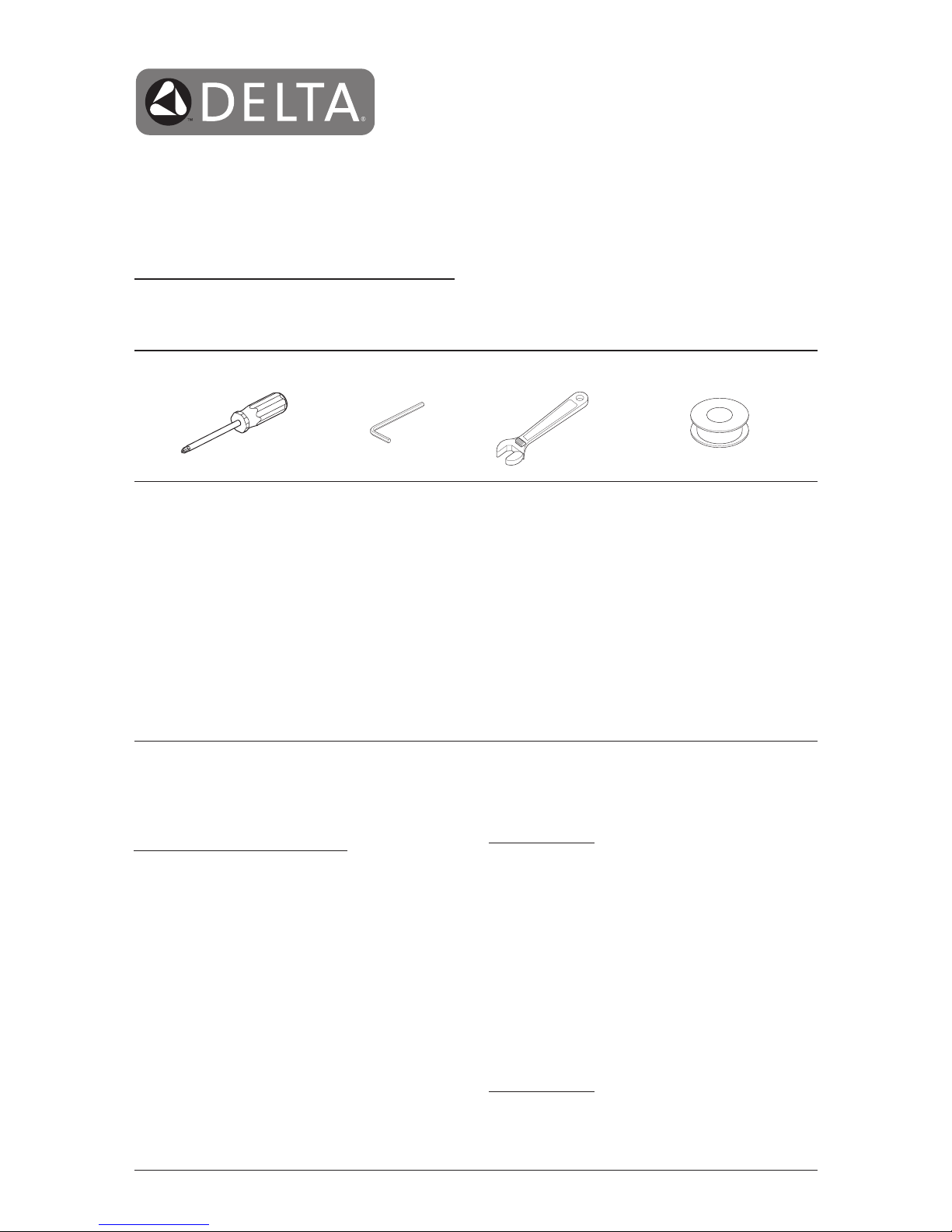
You May Need
Table of Contents:
Warranties ..................................................................................Page 2
Installation Instructions ............................................................... Pages 3 - 5
Clean and care ...........................................................................Page 6
Maintenance ............................................................................... Page 6
Classic Series Replacement Parts .............................................Page 7 - 8
For additional replacement parts, visit www.deltafaucet.com
CAUTION: This system/device must be set by the
installer to ensure safe, maximum temperature.
Any change in the setting may raise the discharge
temperature above the limit considered safe and
may lead to hot water burns.
NOTICE TO INSTALLER: CAUTION! – As the
installer of this valve, it is your responsibility
to properly INSTALL and ADJUST this valve
per the instructions given. This valve does
not automatically adjust for inlet temperature
changes, therefore, someone must make the
necessary Rotational Limit Stop adjustments
at the time of installation and further adjustments
may be necessary due to seasonal water
temperature change. YOU MUST inform the
owner/user of this requirement by following the
instructions.
If you or the owner/user are unsure
how to properly make these adjustments
please
refer to page 6
and if still uncertain, call us at
1-800-345-DELTA.
After installation and adjustment, you must ax
your name, company name and the date you
adjusted the Rotational Limit Stop to the caution
label provided and apply or attach the label to
the back side of the closest cabinet door and
the warning label to the water heater.
Leave
this Instruction Sheet for the owner’s/user’s
reference.
WARNING: This pressure balanced or
thermostatic bath valve is designed
to minimize the effects of outlet water
temperature changes due to inlet pressure
changes, commonly caused by dishwashers,
washing machines, toilets and the like. It may
not provide protection from hot water burns
when there is a failure of other temperature
controlling devices elsewhere in the plumbing
system, if the rotational limit stop is not
properly set or if the hot water temperature is
changed after the settings are made or if the
water inlet changes due to seasonal changes.
WARNING: Do not install a shut-off device on
either outlet of this valve. When this type of
device shuts off the water ow, it can defeat
the ability of the valve to balance the hot and
cold water pressures.
www.deltafaucet.com 08/23/2017 Rev. C
1
887418874188741 88741
Page 2

88741 Rev. C
Lifetime Faucet and Finish Limited Warranty
Parts and Finish
All parts (other than electronic parts and batteries) and
nishes of this Delta® faucet are warranted to the original
consumer purchaser to be free from defects in material
and workmanship for as long as the original consumer
purchaser owns the home in which the faucet was first
installed or, for commercial users, for 5 years from the
date of purchase.
Electronic Parts and Batteries (if applicable)
Electronic parts (other than batteries), if any, of this Delta®
faucet are warranted to the original consumer purchaser
to be free from defects in material and workmanship for 5
years from the date of purchase or, for commercial users,
for one year from the date of purchase. No warranty is
provided on batteries.
Delta Faucet Company will replace, FREE OF CHARGE,
during the applicable warranty period, any part or finish
that proves defective in material and/or workmanship under
normal installation, use and service. If repair or replacement
is not practical, Delta Faucet Company may elect to refund
the purchase price in exchange for the return of the
product.
These are your exclusive remedies.
Delta Faucet Company recommends using a professional
plumber for all installatio and repair.We also recommend
that you use only genuine Delta® replacement parts.
Delta Faucet Company shall not be liable for any damage to
the faucet resulting from misuse, abuse, neglect or improper
or incorrectly performed installation, maintenance or repair,
including failure to follow the applicable care and cleaning
instructions.
Replacement parts may be obtained by calling the applicable
number below or by writing to:
In the United States and Mexico:
Delta Faucet Company
Product Service
55 E. 111th Street
Indianapolis, IN 46280
1-800-345-DELTA (3358)
customerservice@deltafaucet.com
In Canada:
Masco Canada Limited, Plumbing Group
Technical Service Centre
350 South Edgeware Road
St. Thomas, Ontario, Canada N5P 4L1
1-800-345-DELTA (3358)
customerservice@mascocanada.com
Proof of purchase (original sales receipt) from the original
purchaser must be made available to Delta Faucet Company
for all warranty claims unless the purchaser has registered
the product with Delta Faucet Company. This warranty
applies only to Delta® faucets manufactured after January
1,1995 and installed in the United States of America,
Canada and Mexico.
DELTA FAUCET COMPANY SHALL NOT BE LIABLE FOR
ANY
SPECIAL, INCIDENTAL OR CONSEQUENTIAL DAMAGES
(INCLUDING LABOR CHARGES) FOR BREACH OF ANY
EXPRESS OR IMPLIED WARRANTY ON THE FAUCET.
Some states/provinces do not allow the exclusion or
limitation of special, incidental or consequential damages,
so these limitations and exclusions may not apply to you.
This warranty gives you special legal rights. You may also
have other rights which vary from state/province to
state/province.
This is Delta Faucet Company’s exclusive written warranty
and the warranty is not transferable.
If you have any questions or concerns regarding our warranty,
please view our Warranty FAQs at www.deltafaucet.com,
email us at customerservice@deltafaucet.com or call us at
the applicable number above.
Delta HDF Limited Warranty
All parts of the Delta HDF faucet are warranted to the original
consumer purchaser to be free from defects in material and
workmanship for a period of ve (5) years. This warranty is
made to the original consumer purchaser and shall be
effective from date of purchase as shown on purchaser’s
receipt.
Delta will replace, FREE OF CHARGE, during the warranty
period, any part which proves defective in material and/or
workmanship under normal installation, use and service.
Replacement parts can be obtained from your local dealer or
distributor listed in the telephone directory or by returning the
part along with the purchaser’s receipt to our factory,
TRANSPORTATION CHARGES PREPAID, at the address
listed. THIS WARRANTY IS THE ONLY EXPRESS
WARRANTY MADE BY DELTA. ANY CLAIMS MADE
UNDER THIS WARRANTY MUST BE MADE DURING THE
FIVE YEAR PERIOD REFERRED TO ABOVE. ANY
IMPLIED WARRANTIES, INCLUDING THE IMPLIED
WARRANTY OF MERCHANTABILITY OR FITNESS FOR A
PARTICULAR PURPOSE, ARE LIMITED IN DURATION TO
THE DURATION OF THIS WARRANTY. LABOR CHARGES
AND/OR DAMAGE INCURRED IN INSTALLATION, REPAIR
OR REPLACEMENT AS WELL AS INCIDENTAL AND
CONSEQUENTIALDAMAGES CONNECTED THEREWITH
ARE EXCLUDED AND WILL NOT BE PAID BY DELTA.
Some states do not allow limitations on how long an implied
warranty lasts, or the exclusion or limitation of incidental or
consequential damages, so the above limitations or
exclusions may not apply to you.
This warranty gives you specic legal rights, and you may
also have other rights which vary from state to state.
This warranty is void for any damage to this faucet due to
misuse, abuse, neglect, accident, improper installation, any
use violative of instructions furnished by us or any use of
replacement parts other than genuine Delta parts.
www.deltafaucet.com
© 2017 Masco Corporation of Indiana
2
Page 3
88741 Rev. C
Installation
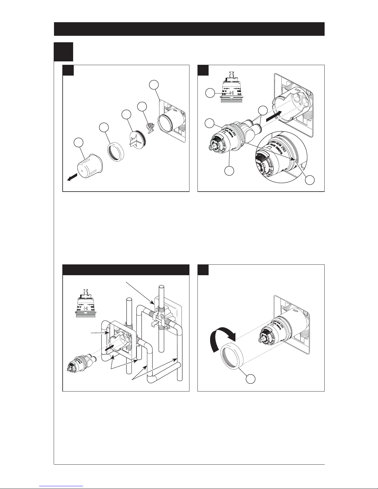
1
Cartridge Installation
A. B.
Turn off water supplies.
Remove
cover (1), bonnet nut (2) and test cap (3)
from the body. If this is not a thin wall
mounting, the entire plasterguard (4)
may be removed. If screen (5) is in place,
remove before installing cartridge.
Rotate the cartridge (1) so the letter
“H” (2) appear on the left. Insert
cartridge into valve body as shown. Make
sure the cartridge tubes and O-rings (3)
are properly seated in holes at the base of
the body. Ensure the keys on the body are
fully engaged with the slots in the body (4).
Back to back Installation C.
For back to back or reverse installations
(hot on right and cold on left) insert the
cartridge with the “H” on the right.
If you are not making a reverse or back
to back installation skip this step and
continue with step 1C.
Slide bonnet nut (1) over the cartridge
and thread onto the body. Hand tighten
securely.
3
Normal Installation (changes not required)
Reverse
Installation
Cold
Hot
2
3
5
4
4
1
4
1
3
2
1
Page 4
88741 Rev. C
Installation
2
4
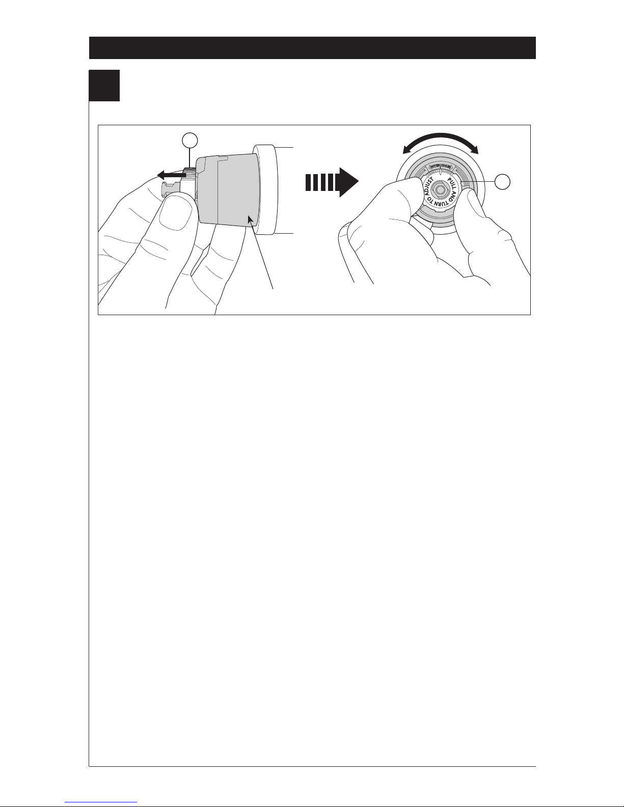
Adjusting the Rotational Limit Stop
IMPORTANT:
The Rotational Limit Stop is used to limit the
amount of hot water available such that, if set
properly, a scald injury is less likely to occur if the
handle accidentally is rotated all the way to “hot”
when a person is showering or lling a tub. The
rst position allows the
LEAST
amount of hot
water to mix with the cold water in the system.
In the rst position the water will be the coldest
possible when the handle is turned all the way
to hot. As you move the Rotational Limit Stop
counterclockwise, you progressively add more
and more hot water in the mix. The last position
to the left will result in the greatest amount of hot
water to the mix, and the greatest risk of scald
injury if someone accidentally turns the valve
handle all the way to the hot side while showering
or lling a tub.
WARNING: In some instances, setting the
Rotational Limit Stop in the hottest position
(full counterclockwise) could result in scald
injury. It is necessary to adjust the Rotational
Limit Stop so that the water coming out of the
valve will not scald the user when the handle
of the valve is rotated to the hot side.
• According to the majority of industry standards,
the maximum allowable temperature of the water
exiting the valve is 120°F (Your local plumbing
codes may require a water temperature less than
120°F).
• The Rotational Limit Stop may need to be readjusted seasonally if the inlet water temperature
changes. For example, during the winter, the
cold water temperature is colder than it is
during the summer which could result in varying
outlet temperatures. A water temperature for
a comfortable bath or shower is typically
between 90°F - 110°F.
• Run the water so that the cold water is as
cold as it will get and hot water is as hot as
it will get. Place the handle on the stem (see
page 6, step 3C) and rotate the handle counterclockwise until the handle stops.
• Place a thermometer in a plastic tumbler
and hold in the water stream. If the water
temperature is above 120°F, the Rotational
Limit Stop must be repositioned clockwise to
decrease valve outlet water temperature to
be
less than 120°F or to meet the
requirements of
your local plumbing codes.
• To adjust the temperature of the water
coming out of the valve, pull the white
Rotational Limit Stop (1) outward and rotate.
Clockwise rotation will decrease the outlet
temperature, counterclockwise rotation will
increase the outlet temperature. Temperature
change per tooth (notch) could be 4° - 16°F
based on inlet water conditions. Repeat as
necessary. When nished, make sure that the
Rotational Limit Stop is fully retracted into the
seated position.
WARNING: Do not take the
Rotational Limit Stop apart.
• MAKE SURE COLD WATER FLOWS
FROM THE VALVE FIRST. MAKE SURE
WATER FLOWING FROM THE VALVE AT
THE HOTTEST FLOW POSSIBLE DOES
NOT EXCEED 120°F OR THE MAXIMUM
ALLOWED BY YOUR LOCAL PLUMBING
CODE.
Hotter
Cooler
1
1
RLS with pull/turn adjustment
Page 5
88741 Rev. C
Installation
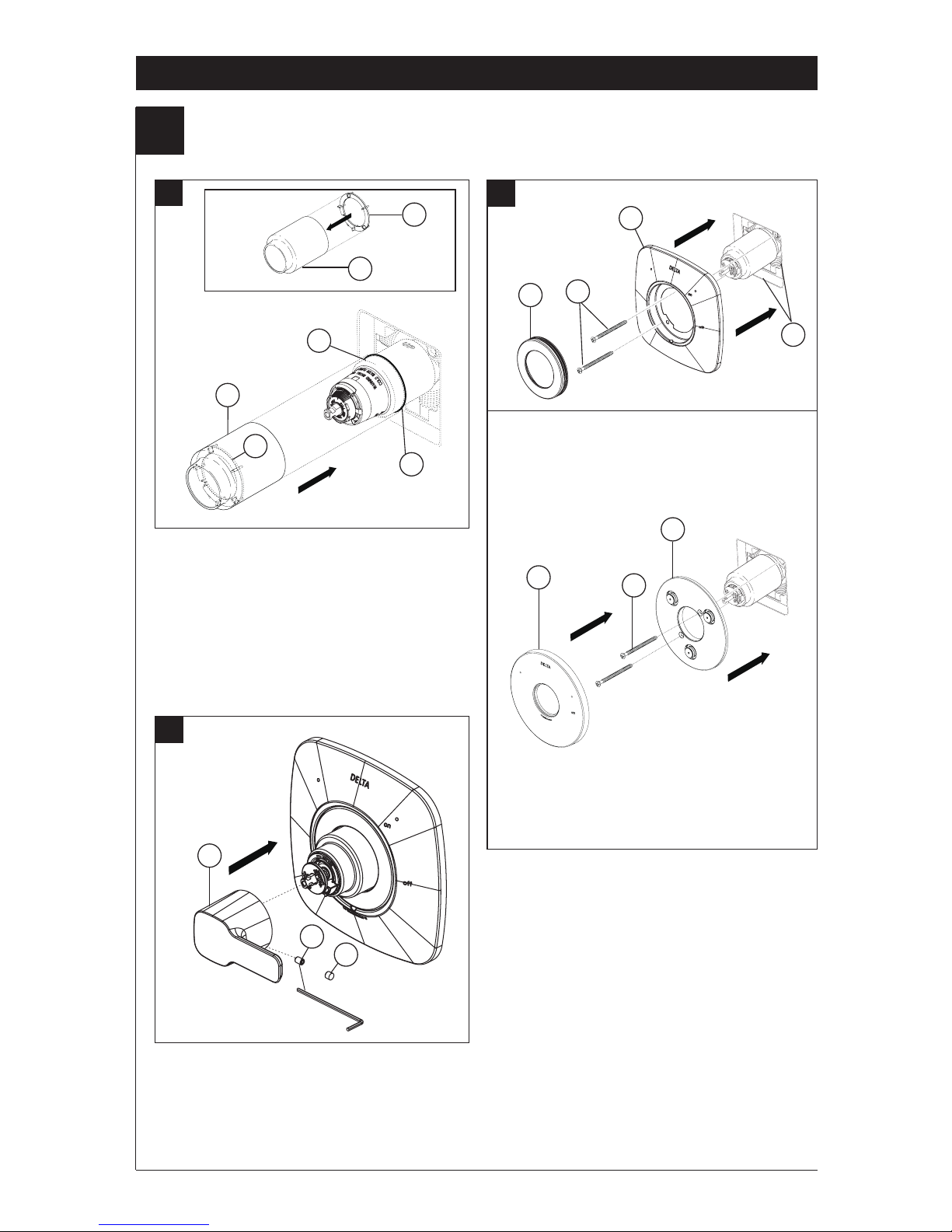
3
Trim Installation
A.
B.
Escutcheon Installation for
Models T140335, T14044T
Slide O-ring (1) over cartridge and the
bonnet nut (2). The O-ring, which acts as
a spacer to steady the sleeve, should rest
behind the bonnet nut.
If your model requires a spacer (3), insert
it into the sleeve (4) and push it to the
front. Slide the sleeve over the cartridge,
body and O-ring.
Using an Allen wrench to secure the set
screw (1), install the handle (2) onto the
stem. Insert plug button (3) (if your model
has one) into set screw hole.
Secure the escutcheon (1) to the bracket
(2) using the 2 screws provided (3). Do not
overtighten escutcheon screws.
If you are
installing the models T140339:
Thread the
cover (4) onto the escutcheon (1).
For models T140335, T140440T:
Install bracket (5) over the cartridge body using
the 2 screws provided (6). Install escutcheon (7)
by placing it over the bracket.
C.
5
1
2
3
4
2
4
3
1
2
3
4
5
6
7
3
1
Page 6

88741 Rev. C
Clean and Care
Care should be given to the cleaning
of this product. Although its nish is
extremely durable, it can be damaged by
harsh abrasives or polish. To clean, simply
wipe gently with a damp cloth and blot dry
with a soft towel.
Warning:
Scrubbing Bubbles® Bathroom
Cleaner and Lysol®Basin Tub and Tile
Cleaner
must not be used on the clear knob
handles and levers. Use of these cleaners
can result in cracked or severely damaged
handles. If overspray gets onto the handles,
immediately wipe them dry with a soft
cotton cloth.
Maintenance
Faucet leaks from tub spout/showerhead:
SHUT OFF WATER SUPPLIES.
Replace seats and springs–Repair
Kit RP4993. Check condition of lower O-rings and
replace if necessary RP14414. See Helpful Hints 1,
2, & 3.
If leak persists:
SHUT OFF WATER SUPPLIES.
Replace valve cartridge RP46074.
See Helpful Hints 1, 2, 3, 4 & 5
Unable to maintain constant
water temperature:
Replace housing assembly with RP46074 or follow
instructions in Helpful Hints 1, 2, 3, 4 & 5.
Helpful Hints:
1. Before removing valve cartridge assembly for any
maintenance, be sure to note the position of the
rotational limit stop on the cap. The valve cartridge
assembly must always be put back in the same
position. BE SAFE! After you have nished the
installation, turn on valve to make sure COLD
WATER FLOWS FIRST.
2. To remove valve cartridge from body, shut o
water supplies and remove handle and bonnet nut.
Do not pry the valve cartridge out of the body with
a screwdriver. Place handle on stem and rotate
counterclockwise approximately 1/4 turn after the
stop has been contacted. Lift valve cartridge out
of body.
3. To remove seats and springs.
Remove valve cartridge. Separate cap assembly
from the housing assembly by rotating the cap
assembly counterclockwise 90 o (degrees).
Separate cap and housing assemblies.
4. If the water in your area has lime, rust, sand
or other contaminants in it, your pressure
balance valve will require periodic inspection.
The frequency of the inspection will depend
on the amount of contaminants in the water. To
inspect valve cartridge remove it and follow the
steps in note 1 above. Turn the valve to the full
mix position and shake the cartridge vigorously.
If there is a rattling sound, the unit is functional
and can be reinstalled following instructions given
in note 1 above. If there is no rattle, replace the
housing assembly with the proper RP.
5. Push disc until fully seated. See page 6 for
more details
6
Page 7
Instrucciones para la
Instalación del Accesorio
para Válvulas MultiChoice
®
Manual para los
Propietarios
Escriba aquí el número del modelo comprado.
Usted puede necesitar
Contenido:
Garantías .................................................................................... Page 2
Instrucciones de Instalación .......................................................Pages 3 - 5
Limpieza y Cuidado de su Liave.................................................Page 6
Mantenimiento ............................................................................ Page 6
Piezas de Repuesto ...................................................................Page 7 - 8
Para las piezas de repuesto adicionales, visite www.deltafaucet.com
Límite Rotacional y aplicar o jar la etiqueta al
dorso de la puerta del gabinete más cercano y la
etiqueta de aviso al calentador de agua. Deje la
Hoja de Instrucciones para referencia del dueño/
usuario.
ADVERTENCIA: Esta válvula de presión
balanceada y termostática está diseñada
para minimizar los efectos de los cambios de
temperatura de agua por causa de los cambios
de presión en el agua de entrada, comúnmente
causados por lavadoras de platos, lavadoras
de ropa, inodoros, y otros aparatos por el
estilo. Puede no proporcionar protección de
quemaduras de agua caliente cuando hay
alguna falla de otros aparatos para el control
de temperatura en otro sitio en el sistema de
plomería. También no proporcionará protección
si el tope del límite rotacional la temperatura
no está apropiadamente jo o si cambia la
temperatura del agua caliente después de
hacer los ajustes o si los cambios del gua de
entrada son por los cambios estacionales.
ADVERTENCIA: No instale un aparato de corte
o cierre en cualquiera de las tomas de esta
válvula. Cuando este tipo de aparato cierra el
ujo de agua, puede hacer fallar la habilidad de
la válvula de balancear las presiones del agua
caliente y fría.
El instalador debe apostar este systema/divisa para
garantizar temperatura maximo y seguro. Cualqueir
cambio en el ajuste puede subir la temperatura
del agua de descarga sobre el límite considerado
seguro y puede resultar en quemaduras de agua
caliente.
AVISO PARA EL INSTALADOR:
PRECAUCIÓN – Como instalador de esta
válvula, es su responsabilidad de INSTALAR Y
AJUSTAR apropiadamente esta válvula como
se describe en las instrucciones, por lo tanto,
debe haber una persona para hacer los ajustes
necesarios del Tope del Límite Rotacional y del
pomo para la temperatura en el momento que
se haga la instalación y pueda necesitar ajustes
adicionales por los cambios estacionales de la
temperatura del agua. USTED DEBE informarle
al dueño/usuario sobre este requisito siguiendo
las instrucciones. Si usted o el dueño/usuario
no están seguros como hacer estos ajustes
apropiadamente, por favor reérase al Página
6
y si todavía no está seguro, llámenos al
1-800-345-DELTA.
Después de hacer la instalación y el ajuste,
usted puede agregarle a la etiqueta de aviso
proporcionada, su nombre, el nombre de
lacompañía y la fecha cuando ajustó el Tope del
compañía y la fecha cuando ajustó el Tope del
T
E
F
L
O
N
88741 Rev. C
1
08/23/2017
T140339
T140335
T140440T
Page 8

88741 Rev. C
Garantía Limitada De Por Vida de la Llave y su Acabado
Piezas y acabado
Todas las piezas (excepto las piezas electrónicas y las
pilas) y los acabados de esta llave de agua Delta
®
están garantizados al consumidor comprador original de
estar libres de defectos en material y fabricación
durante el tiempo que el comprador original posea la
vivienda en la que la llave de agua fue originalmente
instalada o, para los consumidores comerciales, durante
5 años a partir de la fecha de compra.
Componentes electrónicos y pilas (si aplicable)
Todas las piezas (salvo las pilas), si hay, de esta llave
de agua Delta® están garantizadas al consumidor
comprador original de estar libres de defectos en
materiales y fabricación durante 5 años a partir de la
fecha de compra o, para los usuarios comerciales, por
un año a partir de la fecha de compra. No se garantizan
las pilas.
Delta Faucet Company reemplazará, SIN CARGO,
durante el período de garantía aplicable, cualquier pieza
o acabado que pruebe tener defectos de material y/o
fabricación bajo la instalación, uso y servicio normal. Si
la reparación o su reemplazo no es práctico, Delta
Faucet Company tiene la opción de reembolsarle su
dinero por la cantidad del precio de compra a cambio de
la devolución del producto.
Estos son sus únicos
recursos.
Delta Faucet Company recomienda que use los
servicios de un plomero profesional para todas las
instalaciones y reparaciones. También le recomendamos
que utilice sólo las piezas de repuesto
originales de Delta®.
Delta Faucet Company no será responsable por
cualquier daño a la llave de agua que resulte del
mal uso, abuso, negligencia o mala instalación o
mantenimiento o reparación incorrecta, incluyendo
el no seguir los cuidados aplicables y las instrucciones
de limpieza.
Las piezas de repuesto se pueden obtener llamando al
número correspondiente más abajo, o
escribiendo a:
En los Estados Unidos y México:
Delta Faucet Company
Product Service
55 E. 111th Street
Indianapolis, IN 46280
1 800 345 DELTA (3358)
customerservice@deltafaucet.com
En Canadá:
Masco Canada Limited, Plumbing Group
Technical Service Centre
350 South Edgeware Road
St. Thomas, Ontario, Canada N5P 4L1
1 800 345 DELTA (3358)
customerservice@mascocanada.com
La prueba de compra (recibo original) del comprador
original debe ser disponible a Delta Faucet Company para
todos los reclamos a menos que el comprador haya
registrado el producto con Delta Faucet Company. Esta
garantía le aplica sólo a las llaves de agua de Delta
®
fabricadas después del 1 de enero 1995 e instaladas en los
Estados Unidos de América, Canadá y México.
DELTA FAUCET COMPANY NO SE HACE RESPONSABLE
POR CUALQUIER DAÑO ESPECIAL, INCIDENTAL
O CONSECUENTE (INCLUYENDO LOS GASTOS DE
MANO DE OBRA) POR EL INCUMPLIMIENTO DE
CUALQUIER GARANTÍA EXPRESA O IMPLÍCITA DE LA
LLAVE DE AGUA. Algunos estados/provincias no permiten la
exclusión o limitación de daños especiales, incidentales o
consecuentes, por lo que estas limitaciones y exclusiones
pueden no aplicarle a usted. Esta garantía le otorga
derechos legales. Usted también puede tener otros
derechos que varían de estado/provincia a estado/provincia.
Esta es la garantía exclusiva por escrito de Delta Faucet
Company y la garantía no es transferible.
Si usted tiene alguna pregunta o inquietud acerca de
nuestra garantía, por favor, vea nuestra sección de
preguntas frecuentes FAQ sobre la garantía en
www.deltafaucet.com, también puede enviarnos un correo
electrónico a customerservice@deltafaucet.com o llámenos
al número que le corresponda anteriormente incluido.
Garantia Limitada de Delta HDF
Todas las piezas de la llave Delta HDF están
garantizadas al dueño original de estar libres de
defectos en materiales y en la mano de obra por un
período de cinco (5) años. Esta garantía se hace al
dueño original y será efectiva el día de la compra como
se ve en el recibo de compra.
Delta reemplazará, LIBRE DE CARGO, durante el
período de la garantía, cualquier pieza que resulte
defectuosa en materiales y/o en la mano de obra bajo
instalación, uso y servicio normal. Las piezas de
repuesto pueden ser obtenidas de su comerciante o
distribuidor local que se encuentran en la guía telefónica
o si usted devuelve la pieza con el recibo de compra
a nuestra fabrica, Y LOS CARGOS DE TRANSPORTE
PAGADOS CON ANTELACION, a la dirección dada.
ESTA GARANTIA ES LA UNICA GARANTIA EXPRESA
DE DELTA. CUALQUIER RECLAMO HECHO BAJO
ESTA GARANTIA TIENE QUE SER HECHO DURANTE
EL PERIODO DE CINCO AÑOS A QUE SE REFIERE
ARRIBA. CUALQUIER GARANTIA IMPLICITA,
INCLUYENDO LA GARANTIA IMPLICITA DE
COMERCIALIZACION O CONVENIENCIA PARA UN
PROPOSITO PARTICULAR, SON LIMITADOS EN
DURACION A LA DURACION DE ESTA GARANTIA.
LOS CARGOS PARA LA MANO DE OBRA Y/O DAÑOS
INCURRIDOS EN LA INSTALACION, REPARACION O
REEMPLAZO, ASI COMO LOS DAÑOS INCIDENTALES
O CONSECUENTES CONECTADOS CON
ELLOS SON EXCLUIDOS Y NO SERAN PAGADOS
POR DELTA.
Algunos estados no permiten limitaciones al tiempo que
dura la garantía implícita, o la exclusión o limitación de
los daños incidentales o consecuentes, así que la
limitación o exclusión expresada arriba puede no ser
aplicable a usted.
Esta garantía le da a usted derechos legales especícos
y usted puede también tener otros derechos que varían
de estado a estado.
Esta garantía es nula por cualquier daño a esta llave
que sea el resultado del mal uso, abuso, negligencia,
accidente, instalación impropia, cualquier uso en
violación de las instrucciones suministradas por
nosotros o cualquier uso de piezas de repuesto que no
sean piezas genuinas Delta.
www.deltafaucet.com
© 2017 Masco Corporación de Indiana
2
Page 9

88741 Rev. C
Instalación
1
Instalación del Cartucho
A. B.
Cierre los suministros de agua.
Quite la
cubierta (1), la tuerca tapa (2) y la tapa de
prueba (3). Si no es para instalar en pared
delgada, puede quitar el protector (4) de yeso
completo. Si la pantalla (5) está en lugar, quite
antes de instalar el cartucho.
Gire el cartucho (1) de manera que las alfabeto
‘H’ (lado caliente) (2) aparezcan a la
izquierda. Introduzca el cartucho en la válvula
como se muestra. Asegúrese que los tubos del
cartucho y los aros-O (3) estén apropiadamente
sentados en los agujeros en la base del cuerpo
de la válvula. Asegúrese que la parte dentada en
el cuerpo de la pieza encaje completamente en
las muescas de éste (4).
Instalación de Espalda a Espalda
C.
En las instalaciones dorso con dorso o al
reverso (caliente en la derecha y fría en
la izquierda) introduzca el cartucho con la
inscripción “H” a la derecha. Si usted
no está instalando al reverso o dorso con
dorso omita este paso y continúe con el
paso 1C.
Deslice la tuerca tapa (1) sobre el cartucho
y enrosque en el cuerpo de la válvula.
Apriete a mano bien.
3
Instalación Normal (No serequerá cambios)
Instalación
Invertido
Fría
Caliente
1
1
4
2
3
3
5
4
4
1
2
Page 10

88741 Rev. C
Instalación
4
El Ajuste del Tope que Limita la Rotación
2
IMPORTANTE:
El Ajuste del Tope que Limita la Rotación se
usa para limitar la cantidad de agua caliente
disponible de manera que, si ajustado
apropiadamente, Una lesión de escaldado es
menos probable que se ocurra si la manija
se gira accidentalmente completamente a
“hot” (“caliente”) cuando una persona se está
duchando o llenando la bañera. La primera
posición permite la cantidad
MÍNIMA
de
agua caliente mixta con la fría en el sistema.
En la primera posición el agua estará lo
más fría posible cuando la manija se gira
completamente a caliente. Mientras que mueve
el Ajuste del Tope que Limita la Rotación en
dirección contrario a las manecillas del reloj,
progresivamente aumentará el agua caliente
en la mezcla más y más. La última posición
a la izquierda es la de mayor cantidad de
agua caliente en la mezcla, y tiene el mayor
riesgo de lesión por quemadura si alguien
accidentalmente abre la manija de la válvula
completamente a la posición caliente mientras
que se baña o llena la bañera.
•
ADVERTENCIA: En algunos casos, ajustar
el Ajuste del Tope que Limita la Rotación
en la posición más caliente (completamente
en el sentido contrario a la dirección de
las manecillas del reloj) puede resultar en
lesión por quemadura. Es necesario ajustar
el Tope que Limita la Rotación de manera
que el agua que sale de la válvula no queme
o escalde al usuario cuando la manija de la
válvula se gira al lado caliente.
• De acuerdo con la mayoría de los estándares
de la industria, la temperatura máxima
permisible del agua que sale es 120°F (Sus
códigos locales de plomería pueden requerir
una temperatura de agua menor de 120°F).
• El Tope que Limita la Rotación puede requerir
el ajuste estacional si la temperatura del agua
cambia. Por ejemplo, durante el invierno, la
temperatura del agua fría es más fría que
durante el verano resultando en tem-peraturas
variadas en el agua de salida. Una temperatura
de agua para un baño o ducha confortable
típicamente es entre 90°F - 110°F.
• Deje que el agua corra de manera que el
agua fría esté lo más fría posible y la caliente
esté lo más caliente posible. Coloque la manija
en la espiga (vea la página 6, paso 3C) y gire la
manija en dirección contraria a las manecillas
del reloj hasta que la manija pare.
• Coloque el termómetro en un vaso plástico y
sosténgalo bajo el chorro de agua. Si la temperatura de agua está por encima de 120°F el
tope que limita la rotación debe ajustarse otra
vez moviéndolo en sentido de las manecillas
del reloj para reducir la temperatura del agua de
salida de la válvula a menos de 120°F o para
que cumpla con los requisitos de sus códigos
locales de plomería.
• Para ajustar la temperatura del agua que
sale de la válvula, Tirar la Parada de Límite
Rotacional de color blanco hacia afuera y
girarla. Al mover en dirección de las manecillas
del reloj reducirá la temperatura del agua de
salida, y al contrario aumentará la temperatura
del agua de salida. El cambio de temperatura
por cada diente (muesca) puede ser de
4°F-16°F dependiendo de la condición del agua
de entrada. Si es necesario repítalo. Cuando
haya terminado, asegúrese de que la Parada de
Límite Rotacional esté completamente retraída
a la posición sentada.
ADVERTENCIA: No
tome la Parada de Límite Rotacional aparte.
• ASEGÚRESE QUE EL AGUA FRÍA FLUYA DE
LA VÁLVULA PRIMERO. ASEGÚRESE QUE
EL AGUA QUE FLUYE DE LA VÁLVULA EN
LA POSICIÓN MÁS CALIENTE POSIBLE NO
EXCEDA 120°F O EL MÁXIMO PERMITIDO
POR SUS CÓDIGOS LOCALES DE
PLOMERÍA.
Hotter
Cooler
1
1
RLS con ajuste de tracción/giro.
Page 11

88741 Rev. C
Instalación
3
Instalación Final
B.
La instalación de la roseta para los
modelos T140335, T14044OT
Deslice el aro O (1) sobre el cartucho y la tu-
erca tapa (2). El aro O, el cual funciona como
un separador para estabilizar la manga, debe
quedar apoyado en la tuerca tapa.
Si su modelo requiere un separador (3), in-
sértelo en la manga (4) y empújelo hacia el
frente. Deslice la manga sobre el cartucho,
el cuerpo de la pieza y el aro O.
una llave Allen para jar el tornillo de ajuste
(1). Insertar el botón obturador (3) (si su
modelo tiene uno) en el agujero de tornillo
de ajuste.
Fije la roseta con oricio (1) al soporte (2)
usando los 2 tornillos suministrados (3). No
apriete demasiado los tornillos de la roseta.
Si está instalando the Modelos T140339:
Gira la tapa (4) en la cubierta de oricio (1).
Para los modelos T140335, T140440T:
Instale el soporte (5) sobre el cuerpo del
cartucho usando los 2 tornillos incluidos (6).
Instale la chapa de base (7) colocándola sobre
el soporte.
5
A.
1
3
4
2
4
3
1
2
3
4
5
6
7
C.
2
3
1
Page 12

88741 Rev. C
Limpieza y Cuidado de su Llave
Tenga cuidado al ir a limpiar este producto.
Aunque su acabado es sumamente durable,
puede ser afectado por agentes de limpieza
o para pulir abrasivos. Para limpiar su llave,
simplemente frótela con un trapo húmedo y
luego séquela con una toalla suave.
¡ADVERTENCIA!
No se puede usar
SCRUBBING BUBBLES® BATHROOM
CLEANER o LYSOL® BASIN TUB AND TILE
CLEANER
en las manijas transparentes. El uso
de estos productos pueden resultar en manijas
rajados o severamente dañados. Si estos
productos caen sobre la manija, séquelo
inmediatamente con una toalla de algodón suave.
Mantenimiento
La llave tiene fugas de agua en la
salida de tina/cabeza deregadera–
CIERRE LOS SUMINISTROS DE AGUA.
Reemplace Asientos y Resortes–Equipo de
Reparaciones RP4993 Verica el condición de los
anillos “O” más bajo y repongalos si será necesario
RP14414. Vea Sugerencias Utiles 1, 2, y 3.
Si la fuga de agua persiste–
CIERRE LOS SUMINISTROS DE AGUA.
Reemplace el cartucho de válvula RP46074.
Vea Sugerencia Utiles 1, 2, 3, 4 y 5.
No se puede mantener temperatura de
agua constante:
Reemplace ensamble de caja con RP46074 o sigue
los instrucciones en Sugerencias Utiles 1, 2, 3, 4 y 5.
Sugerencia Utiles:
1. Antes de remover el ensamble del cartucho de
la válvula para hacerle cualquier servicio, fíjese en
la posición del tope del límite rotacional ubicado en
la tapa. Siempre se debe reponer el ensamble de
cartucho de válvula en el mismo posición. TENGA
CUIDADO después de cumplir el instalación dele
vuelta a la válvula para asegurar que AGUA FRIA
SALGA PRIMERO.
2. Para quitar el cartucho de válvula del cuerpo,
cierre los suministros de agua y quite el maneral y
bonete. No se debe quitar el cartucho de válvula
del cuerpo con atornillador. Ponga el maneral
encima el vástago y giralo en el sentido contrario
al de las agujas del reloj aproximado 1/4 vuelta.
Levanta el cartucho de válvula aguera el cuerpo.
3. Para quitar los asientos y resortes.
Quite el cartucho de válvula, (vea arriba). Separa
ensamble de botón de ensamble de caja girando
el botón 90 en el sentido contrario al de las agujas
del reloj.
4. Si la agua en su area contiene cal, orín, arena
o otros contaminamientos, su válvula de equilibrio
de presión requerá inspecciones periódico. La
frequencía de los inspecciones depende en el
tamaño de contaminamientos en la agua. Para
inspectar el cartucho, quite el cartucho, sigue los
pasos apuntado en nota 1 arriba. Dele vuelta al
válvula hasta el posición completamente mixto
y sacude el cartucho riguroso. Si hay traqueteo,
funciona el unidad y se puede reinstalar siguendo
nota 1 de arriba. Si no hay traqueteo, reemplace
el ensamble de caja.
5. Presione el disco hasta que está asentado
completamente. Vea la página 6 para más
detalles.
6
Page 13

88741 Rev. C
Instructions d’installation
Finition de la soupape
MultiChoice
®
Guide d’utilisation
Inscrivez le numéro de modèle ici.
Articles dont vous pouvez avoir besoin:
Table des matières
Garanties .................................................................................... Page 2
Instructions d’installation ............................................................Pages 3 - 5
Instructions de nettoyage ...........................................................Page 6
Maintenance ............................................................................... Page 6
Pièces de rechange ....................................................................Page 7 - 8
Pour les pièces de rechange supplémentaires, visitez www.deltafaucet.com
de température, puis xer l’étiquette à l’endos de la
porte de la coieuse. Vous devez également xer
l’étiquette d’avertissement au chaue-eau.
Veuillez
laisser ce feuillet d’instructions au propriétaire
ou à l’utilisateur pour qu’il puisse le consulter
au besoin.
MISE EN GARDE – Ce robinet thermostatique
à équilibrage de pression pour baignoire est
conçu pour limiter les effets des uctuations de
température de l’eau causées par les variations
de la pression d’alimentation attribuables au
fonctionnement d’un lave-vaisselle, d’une
machine à laver, d’un cabinet d’aisances ou
d’un autre appareil qui consomme de l’eau.
Il peut ne pas protéger l’utilisateur contre
l’échaudage en cas de défectuosité d’un autre
dispositif de régulation de la température,
si le réglage de la butée limitatrice de haute
température est mauvais, si la température
de l’eau chaude a été modiée après que les
réglages ont été effectués ou si la température
de l’eau d’alimentation a changé en raison du
changement de saison.
MISE EN GARDE – N’installez pas de dispositif
d’arrêt sur une sortie quelconque de ce robinet.
En interrompant l’écoulement de l’eau, ce
dispositif peut empêcher le robinet d’équilibrer
les pressions d’eau chaude et d’eau froide.
ATTENTION:
L’installateur doit régler l’appareil
pour que la température maximale de l’eau chaude
soit sans danger. Toute modication des réglage
peut entraîner une élévation de la température à
la sorite du robinet au delà de la température sans
danger et pourrait causer un échaudage.
AVIS À L’INSTALLATEUR : ATTENTION! – En
qualité d’installateur, vous êtes tenu
d’INSTALLER et de RÉGLER ce robinet
conformément aux instructions. Ce robinet ne
s’adapte pas automatiquement aux uctuations
de la température de l’eau d’alimentation. Par
conséquent, il faut régler la butée limitatrice
de température au moment de l’installation et
il peut être nécessaire de faire de nouveaux
réglages par la suite en raison des uctuations
saisonnières de la température de l’eau. VOUS
DEVEZ informer le propriétaire ou l’utilisateur
de cette exigence. En cas de doute quant à
la marche à suivre pour faire ces réglages,
veuillez consulter page 6 si un doute persiste,
et si cette ince rtitude persiste, appelez-nous au
1-800-345-DELTA.
Après avoir terminé l’installation et le réglage, vous
devez inscrire, sur l’étiquette de mise en garde
fournie, votre nom, le nom de votre entreprise et la
fournie, votre nom, le nom de votre entreprise et la
date à laquelle vous avez réglé la butée limitatrice
T
E
F
L
O
N
1
08/23/2017
T140339
T140335
T140440T
Page 14

88741 Rev. C
Garantie à vie limitée des robinets et de leurs nis
Pièces et nis
Toutes les pièces (à l’exception des composants
électroniques et des piles) et tous les nis de ce robinet
Delta® sont protégés contre les défectuosités du matériau
et les vices de fabrication par une garantie qui est
consentie au premier acheteur et qui demeure valide tant
que celui-ci demeure propriétaire de la maison dans
laquelle le robinet a été installé. Dans le cas d’une
utilisation commerciale, la garantie est de 5 ans à compter
de la date d’achat.
Composants électroniques et piles (le cas échéant)
Si ce robinet Delta® comporte des composants
électroniques, ces composants (à l’exception des piles)
sont protégés contre les défectuosités du matériau et les
vices de fabrication par une garantie consentie au premier
acheteur qui est d’une durée de 5 ans à compter de la
date d’achat. Dans le cas d’une utilisation commerciale, la
garantie est d’un an à compter de la date d’achat. Aucune
garantie ne couvre les piles.
Delta Faucet Company remplacera, GRATUITEMENT,
pendant la période de garantie applicable, toute pièce ou
tout ni qui présentera une défectuosité du matériau et/ou
un vice de fabrication pour autant que le robinet ait été
installé, utilisé et entretenu normalement. S’il est
impossible de réparer ou de remplacer le robinet, Delta
Faucet Company pourra décider de rembourser le prix
d’achat du produit pour autant que celui-ci lui soit retourné.
Il s’agit de vos seuls recours.
Delta Faucet Company recommande de coner
l’installation et la réparation à un plombier professionnel.
Nous vous recommandons également d’utiliser
uniquement des pièces de rechange authentiques Delta®.
Delta Faucet Company se dégage de toute responsabilité
à l’égard des dommages causés au robinet en raison d’un
mauvais usage, d’un usage abusi f, de la négligence ou de
l’utilisation d’une méthode d’installation, de maintenance
ou de réparation incorrecte ou inadéquate, y compris
les dommages résultant du non-respect des instructions
de nettoyage et d’entretien applicables. Garantie limitée
des robinets Delta® Pour obtenir des pièces de rechange,
veuillez appeler au numéro applicable ci-dessous ou écrire
à l’adresse applicable ci-dessous.
Aux États-Unis et au Mexique :
Delta Faucet Company
Product Service
55 E. 111th Street
Indianapolis, IN 46280 St.
1-800-345-DELTA (3358)
customerservice@deltafaucet.com
Au Canada:
Masco Canada Limited, Plumbing Guoup
Thechnical Service Centre
350 South Edgware Roard
Thomas, Ontario, Canada N5P 4L1
1-800-345-DELTA (3358)
customerservice@mascocanada.com
La preuve d’achat (reçu original) du premier acheteur doit
être présentée à Delta Faucet Company pour toutes les
demandes en vertu de la garantie, sauf si le produit a été
enregistré auprès de Delta Faucet Company. La présente
garantie s’applique uniquement aux robinets Delta
®
fabriqués après le 1er janvier 1995 et installés aux
États-Unis d’Amérique, au Canada et au Mexique.
DELTA FAUCET COMPANY SE DÉGAGE DE TOUTE
RESPONSABILITÉ À L’ÉGARD DES DOMMAGES
PARTICULIERS, CONSÉCUTIFS OU INDIRECTS (Y
COMPRIS LES FRAIS DE MAIN-D’OEUVRE) QUI
POURRAIENT RÉSULTER DE LA VIOLATION D’UNE
GARANTIE IMPLICITE OU EXPLICITE QUELCONQUE
SUR LE ROBINET. Dans les États ou les provinces
où il est interdit de limiter ou d’exclure la responsabilité à
l’égard des dommages particuliers, consécutifs ou
indirects, les limites et les exclusions susmentionnées ne
s’appliquent pas.
La présente garantie vous donne des droits précis qui
peuvent varier selon l’État ou la province où vous résidez.
La présente garantie écrite est la garantie exclusive oerte
par Delta Faucet Company et elle n’est pas transférable.
Si vous avez des questions ou des préoccupations en ce
qui concerne notre garantie, veuillez consulter la page
Warranty FAQs à www.deltafaucet.com, faire parvenir un
courriel à customerservice@deltafaucet.com ou nous
appeler au numéro applicable.
Garantie Limitée sur les Robinets Ultra-Robustes Delta de la Série HDF
Toutes les pièces des robinets ultra-robustes Delta de la
série HDF sont protégées contre les défectuosités du
matériau et les vices de conception par une garantie qui
est consentie au premier acheteur pour une période de
cinq (5) ans. Cette garantie entre en vigueur à compter de
la date d’achat indiquée sur le reçu de l’acheteur.
Pendant la période de garantie, Delta remplacera, SANS
FRAIS, toute pièce présentant une défectuosité du
matériau et (ou) un vice de fabrication pour autant que
l’appareil ait été installé, utilisé et entretenu correctement.
Pour obtenir des pièces de rechange, veuillez
communiquer avec le distributeur ou le concessionnaire de
votre région dont le nom gure dans l’annuaire
téléphonique ou retourner la pièce défectueuse
accompagnée du reçu de l’acheteur à notre usine, PORT
PAYÉ, à l’adresse indiquée. LA PRÉSENTE GARANTIE
EST LA SEULE GARANTIE IMPLICITE OFFERTE PAR
DELTA. TOUTE RÉCLAMATION EN VERTU DE CETTE
GARANTIE DOIT ÊTRE FAITE AU COURS DE LA
PÉRIODE DE CINQ ANS SUSMENTIONNÉE. TOUTE
GARANTIE IMPLICITE, Y COMPRIS LA GARANTIE
IMPLICITE DE QUALITÉ MARCHANDE OU
D’ADÉQUATION DU PRODUIT AVEC UN USAGE
PARTICULIER, EST LIMITÉE À LA DURÉE DE LA
PRÉSENTE GARANTIE. LES FRAIS DE
MAIN-D’OEUVRE ET (OU) LES DOMMAGES
PROVOQUÉS AU COURS DE L’INSTALLATION, DE LA
RÉPARATION OU DU REMPLACEMENT D’UN
ÉLÉMENT AINSI QUE LES PERTES OU LES
DOMMAGES INDIRECTS EN RÉSULTANT NE SONT
PAS COUVERTS PAR CETTE GARANTIE.
Là où il est interdit de limiter la durée de la garantie
implicite ou les responsabilités à l’égard des dommages
indirects, les exclusions et les limites susmentionnées ne
s’appliquent pas.
La présente garantie vous donne des droits précis qui
peuvent varier selon votre lieu de résidence.
Les dommages résultant d’une mauvaise utilisation, d’une
utilisation abusive, de la négligence, d’un accident, d’une
mauvaise installation, du non respect de nos instructions
ou de l’utilisation de pièces de rechange autres que des
pièces d’origine Delta ne sont pas couverts par la garantie.
www.deltafaucet.com
© 2017 Division de Masco Indiana
2
Page 15

88741 Rev. C
Installation
1
Installation de la cartouche
A. B.
Interrompez l’arrivée d’eau.
Enlevez le
couvercle (1), l’écrou à portée sphérique (2)
et le capuchon d’essai (3) du corps.
Si vous n’installez pas l’appareil dans une
paroi mince, vous pouvez retirer le protecteur
(4) complètement. Si l’écran (5)
est en place, enlevez avant d’installer
la cartouche.
Tournez la cartouche (1) de sorte que la
mention « H » (2) se trouve du côté
gauche. Introduisez la cartouche dans le
corps de la soupape comme le montre la
gure. Assurez-vous que les tubes et les
joints toriques (3) de la cartouche sont bien
calés à la base du corps. Assurez-vous que
les ergots sur le corps sont parfaitement
engagés dans les rainures du corps (4).
Installation dos à dos
C.
Dans le cas d’une installation dos à dos
ou inversée (eau chaude à droite et eau
froide à gauche), introduisez la cartouche
de sorte que la mention « H » se
trouve du côté droit. S’il ne s’agit pas d’une
installation dos à dos ou inversée, sautez
la présente étape et passez à l’étape 1C.
Faites glisser l’écrou à portée sphérique
(1) sur la cartouche et vissez-le sur le
corps. Serrez à la main fermement.
3
Installation normale (Non modiée)
Installation
Inversée
Eau Froides
Eau Chaude
1
2
3
5
4
4
4
3
1
1
2
Page 16

88741 Rev. C
Installation
4
2
Réglage de la butée anti-échaudage
IMPORTANT:
La butée antiéchaudage sert à limiter la
quantité d’eau chaude disponible de sorte
Une blessure par échaudage est moins
susceptible de se produire. si la manette
est amenée à l’extrémité de la plage du
côté « Eau chaude » par inadvertance alors
que quelqu’un se trouve sous la douche
ou dans la baignoire. La première position
est celle qui laisse passer le MOINS d’eau
chaude à mélanger avec l’eau froide. À la
première position, l’eau est aussi froide que
possible alors que la manette se trouve à
l’extrémité de la plage du côté « Eau chaude
». En tournant la butée antiéchaudage, vous
ajoutez progressivement de plus en plus d’eau
chaude au mélange. La dernière position
à gauche est celle qui laisse passer le plus
d’eau chaude et le risque d’ébouillantage est
plus élevé si quelqu’un amène la manette à
l’extrémité de la plage du côté « Eau chaude
» par inadvertance alors que quelqu’un
d’autre se trouve sous la douche ou dans la
baignoire.
MISE EN GARDE : Dans certains cas,
l’ébouillantage est possible si la butée
antiéchaudage se trouve à la position
la plus chaude (à l’extrémité de la plage
dans le sens antihoraire). Il faut régler la
butée antiéchaudage de manière que l’eau
s’écoulant du robinet ne puisse causer de
brûlures à l’usager alors que la manette
est à la position « Eau chaude ».
• Selon la plupart des normes en vigueur
dans l’industrie, la température de l’eau à la
sortie du robinet ne doit pas dépasser 120
°F (certains codes de plomberie peuvent
prescrire une température inférieure à cette
valeur).
• La butée antiéchaudage peut devoir être
réglée à chaque saison si la température de
l’eau d’alimentation change. Par exemple, la
température de l’eau froide est plus basse
en hiver qu’en été, ce qui peut entraîner une
variation de la température à la sortie du
robinet. La température idéale pour la douche
ou le bain se situe généralement entre
90 °F - 110 °F.
• Faites couler l’eau de sorte qu’elle soit
aussi froide que possible et aussi chaude que
possible. Placez ensuite la manette sur la
tige (reportez-vous à la page 6, étape 3C) et
tournez la manette dans le sens antihoraire
jusqu’à l’extrémité de la plage.
• Placez un thermomètre dans un gobelet en
plastique et mettez celui-ci sous le jet d’eau.
Si la température de l’eau est supérieure à
120°F, tournez la butée antiéchaudage dans
le sens horaire pour abaisser la température
de l’eau à la sortie du robinet sous 120°F
ou à une valeur conforme aux exigences du
code de plomberie de votre région.
• Pour régler la température de l’eau qui
s’écoule de la soupape, Tirez vers extérieur
l’arrêt de limite de rotation et tournez. La
température diminue dans le sens horaire
et augmente dans le sens antihoraire. La
variation de température est de 4 à 16 °F
par cran, selon la température de l’eau
d’alimentation. Refaites le réglage au besoin.
Lorsque vous avez ni, assurez-vous que
l’arrêt de limite de rotation soit complètement
rétracté dans sa position de logement.
AVERTISSEMENT: Ne détachez pas l’arrêt
de limite de rotation.
• ASSUREZ-VOUS QUE L’EAU FROIDE
S’ÉCOULE DE LA SOUPAPE EN PREMIER.
ASSUREZ-VOUS QUE LA TEMPÉRATURE
DE L’EAU NE PEUT DÉPASSER 120 °F
OU LA VALEUR MAXIMALE AUTORISÉE
PAR LE CODE DE PLOMBERIE DE VOTRE
RÉGION.
Hotter
1
1
RLS avec ajustement retirer/retourner.
Page 17

88741 Rev. C
Installation
3
Installation des pièces de nition
B.
Installation de la rosace pour les
modèles T140335, T140440T
Montez la manette (2) sur la tige et
bloquez-la en place en serrant la vis de cal-
age (1) avec une clé Allen.Bouton Insérer
le bouchon (3) (si votre modèle a un) dans
le trou de la vis de réglage.
Fixez la rosace (1) sur le support (2) à l’aide des
2 vis fournies (2). Prenez garde de serrerles vis de
la rosace excessivement.
Si vous installez Modèles T140339:
Enlez le couvercle (5) sur l'écusson (1).
Pour les modèles T140335, T140440T:
Montez la xation (5) sur le corps de la cartouche
à l’aide des 2 vis fournies (6). Installez la plaque
de nition (7) en la plaçant sur la xation comme
le montre la gure.
5
Faites glisser le joint torique (1) sur la
cartouche et l’écrou à portée sphérique
(2). Le joint sert de pièce d’espacement
et il stabilise le manchon; il doit se trouver
derrière l’écrou à portée sphérique.
Si le modèle que vous installez nécessite
une pièce d’espacement (3), introduisezla
dans le manchon (4) et poussez-la vers
l’avant. Faites glisser le manchon sur la
cartouche, le corps et le joint torique.
A.
1
3
4
2
4
3
1
2
3
4
5
6
7
C.
2
3
1
Page 18

88741 Rev. C
Instructions de nettoyage
Il faut le nettoyer avec soin. Même si son
ni est extrêmement durable, il peut être
abîmé par des produits fortement abrasifs
ou des produits de polissage. Il faut
simplement le frotter doucement avec un
chion humide et le sécher à l'aide d'un
chion doux.
de Baignoires et de Carreaux Lysol®
sur
les manettes et les poignées sphériques
transparentes. Ces produits peuvent faire
ssurer les poignées et les manettes ou
les abîmer gravement. Si ces poigneés
ou ces manettes sont aspergées
accidentellement par l’un ou l’autre
des produits mentionnés, les essuyer
immédiatement à l’aide d’un chion de
coton doux.
Maintenance
Le robinet fuit par le bec ou la pomme de
douche. COUPER L’EAU.
Remplacer les sièges et les ressorts (kit de
réparation RP4993. Vérier l’état des joints toriques
inférieurs et remplacer ceux-ci au besoin (RP14414).
Voir les conseils 1, 2, et 3.
Si la fuite persiste, COUPER L’EAU.
Remplacer la cartouche RP46074.
Voir les conseils 1, 2, 3, 4 et 5.
La tempétature de l’eau n’est pas constante.
Remplacer le boîtier par un boîtier RP46074 ou
suivre les instructions des conseils 1, 2, 3, 4 et 5.
Conseils:
1. Avant d’enlever la cartouche de la soupape aux
ns d’entretien, prenez note de la position de la
butée de température maximale sur le chapeau.
La cartouche doit toujours être reposée dans la
même position. NE PAS PRENDRE DE RISQUES
INUTILEMENT. Une fois l’installation terminée,
ouvrir le robinet pour s’assurer que L’EAU FROIDE
S’ÉCOULE EN PREMIER.
2. Pour déposer la cartouche du corps, couper l’
eau,
puis retirer la poignée et le chapeau leté. Ne pas
utiliser un tournevis comme levier pour extraire la
cartouche. Placer la poignée sur la tige et la tourner
dans le sens antihoraire d’environ 1/4 de tour après
contact des butées. Soulever la cartouche pour la
retirer du corps.
3. Pour déposer les sièges et les ressorts
Enlever la cartouche. Séparer la soupape du boîtier
en la tournant de 90 degrés dans le sens antihoraire.
Écarter ensuite la soupape du boîtier.
4. Si l’eau d’alimentation du robinet à équilibrage
de pression renferme du calcaire, du fer, du sable
ou d’autres corps étrangers, celui-ci doit faire
l’objet d’inspections périodiques. La fréquence
des inspections dépend de la quantité de corps
étrangers dans l’eau. Pour inspecter la cartouche,
la déposer et suivre et les instructions de la note 1
ci-dessus. Ouvrir la soupape en position de plein
mélange et secouer la cartouche vigoureusement.
Si des cliquetis se font entendre, le composant est
en bon état et peut être reposé conformément aux
instructions de la note 1 ci-dessus. Si on n’entend
pas de cliquetis, remplacer le boîtier.
5. Remettez le disque jusqu’à ce qu’entièrement
assis. Voir la page 5 pour plus de détails.
6
AVERTISSEMENT: N’employez pas le
nettoyant pour salle de bain Scrubbing
Bubbles
®
ni le Nettoyant de Lavabos,
Page 19

88741 Rev. C
7
T140339 Model / Modelo / Modèle
▲
Specify Finish
Especifíque el Acabado
Précisez le Fini
RP81811
▲
Handle Kit
Juego de herrajes de la Manija
Manette en kit
RP81815
▲
Escutcheon
Roseta
Rosace avec
Orice
RP49089
▲
Trim Ring
Aro de accesorio
Anneau décoratif
RP196
▲
Trim Screws
Atornillos de Franja
Vis de Finition
RP23336
O-Ring
Anillo "O"
Joint Torique
RP29569
Spacer
Separadores
Piéce D'espacement
RP50879
▲
Trim Sleeve
Manga de Fran ja
Manchon de Finition
RP78182
Button & Set Screws
Botón y Tornillo de Ajuste
Bouton et Vis de Calage
RP46074
Ceramic Valve Cartridge
Válvula de Cartucho
Cartouche
RP10700
Seats & Springs
Asientos y Resortes
Sièges et Ressorts
Page 20

88741 Rev. C
8
T140335 & T140440T Models / Modelos / Modèles
▲ Specify Finish
Especifíque el Acabado
Précisez le Fini
RP78185
▲
For 140335
Handle Kit
Juego de herrajes de la Manija
Manette en kit
RP81365
▲
For T140440T
Handle Kit
Juego de herrajes de la Manija
Manette en kit
RP78182
Button & Set Screws
Botón y Tornillo de Ajuste
Bouton et Vis de Calage
RP78181
▲
Deep Escutcheon
Roseta
Rosace avec Orice
RP78180
▲
Escutcheon
Roseta
Rosace avec
Orice
RP196
▲
Trim Screws
Atornillos de Franja
Vis de Finition
RP23336
O-Ring
Anillo "O"
Joint Torique
RP29569
Spacer
Separadores
Piéce D'espacement
RP50879
▲
Trim Sleeve
Manga de Fran ja
Manchon de Finition
RP46074
Ceramic Valve Cartridge
Válvula de Cartucho
Cartouche
RP10700
Seats & Springs
Asientos y Resortes
Sièges et Ressorts
Page 21

88741 Rev. C
Delta Faucet Company
Product Service
55 E. 111th Street
Indianapolis, IN 46280
 Loading...