

Page 1
Installation, Operation &
Maintenance Instructions
Sentry Series
Models P0* (Pressure Switches)
Models D0* (Differential Pressure Switches)
Models T0* (Temperature Switches)
002522-SENTRY-C : FEB 2012
General
The unit is manufactured, checked and supplied in
accordance with our published specification, and
when installed and used in normal or prescribed
applications, with the lid in place and within the
parameters set for mechanical and electrical
performance, will not cause danger or hazard to life or
limb.
THE USERS ATTENTION IS DRAWN TO THE
FACT THAT, WHEN THE UNIT IS ‘LIVE’ WITH
RESPECT TO ELECTRICAL OR PRESSURE
SUPPLIES, A HAZARD MAY EXIST IF THE
UNIT IS OPENED OR DISMANTLED.
UNITS MUST BE SELECTED AND
INSTALLED BY SUITABLY TRAINED AND
QUALIFIED PERSONNEL IN ACCORDANCE
WITH APPROPRIATE CODES OF PRACTICE
SO THAT THE POSSIBILITY OF FAILURE
RESULTING IN INJURY OR DAMAGE
CAUSED BY MISUSE OR MISAPPLICATION
IS AVOIDED.
Operating principles
Pressure Switch models P0* and Differential Pressure Switch models D0* are diaphragm operated
switches.
These diaphragms generate a force proportional to
the applied pressure and are balanced by a user adjustable control spring. When the force exceeds that
created by the control spring, the diaphragm moves
causing a push rod to actuate a snap-acting microswitch.
Temperature models T01 & T02 work in the same
way as the Pressure models with the exception that
the applied pressure comes from the expansion of a
vapour enclosed in either a rigid stem or semi-rigid
thermal system.
occur. They can be mounted either direct to process,
or to a wall or panel using the mounting holes provided. Select the mounting point so as to avoid excessive shock, vibration or temperature fluctuation.
Instruments should be mounted to avoid excessive
heat transfer from the process lines or adjacent plant.
To avoid undue stresses being imparted to the instrument when wall/panel mounted, it is recommended
that a short length of flexible line be installed between
the instrument and process line. If sudden changes of
pressure (pulsations) are likely then we recommend
that snubbers are fitted between the process line and
instrument. Use a spanner to support the process
connection when fitting the instrument.
CHECK THE CONNECTION THREAD SIZE
AND SPECIFICATION ON THE UNIT TO
AVOID MIS-MATCHING WITH THE PROCESS
CONNECTION ADAPTOR. SEE DIGIT 11 OF
PRODUCT CODE.
Mounting (T01 - Rigid Stem)
Assemble the unit via a thermowell, using the
spanner facility provided and ensuring that:
a) the sensing bulb is fully immersed in the
process temperature
b) the sensing bulb does not bottom out in the
thermowell which could cause damage
Mounting (T02 - Capillary system)
Mount the sensing bulb so that the capillary end is
above the bulb and the bulb is level with, or no more
than 250mm below the base of the instrument. The
stem is fitted with a sliding compression gland to
accommodate different thermowells.
Wiring
DISCONNECT ALL SUPPLY CIRCUITS
BEFORE WIRING
INSTALLATION
Mounting (All models)
The instruments are designed to be mounted vertically
with the process connection underneath. However,
mounting up to 45° from the vertical in any plane is
acceptable, although a small calibration shift may
www.delta-controls.com
WIRE IN ACCORDANCE WITH LOCAL AND
NATIONAL CODES. USE CABLES NO
LARGER THAN 2.5 MM2 (14 AWG)
DO NOT EXCEED ELECTRICAL RATINGS
STATED IN LITERATURE AND ON
NAMEPLATES.
Page 2
002522-SENTRY-C : FEB 2012
Wiring (continued...)
Undo the single lid retaining screw and allow the
hinged lid to rest in an open position. Be careful not to
apply excessive pressure on the opened lid to avoid
damage to the hinge.
IF HINGE IS DAMAGED, INGRESS
PROTECTION LEVEL COULD BE
COMPROMISED.
A single M20 or ½”NPT electrical entry is provided,
into which a cable gland can be assembled. Select a
suitable cable gland which will maintain the IP rating of
the instrument.
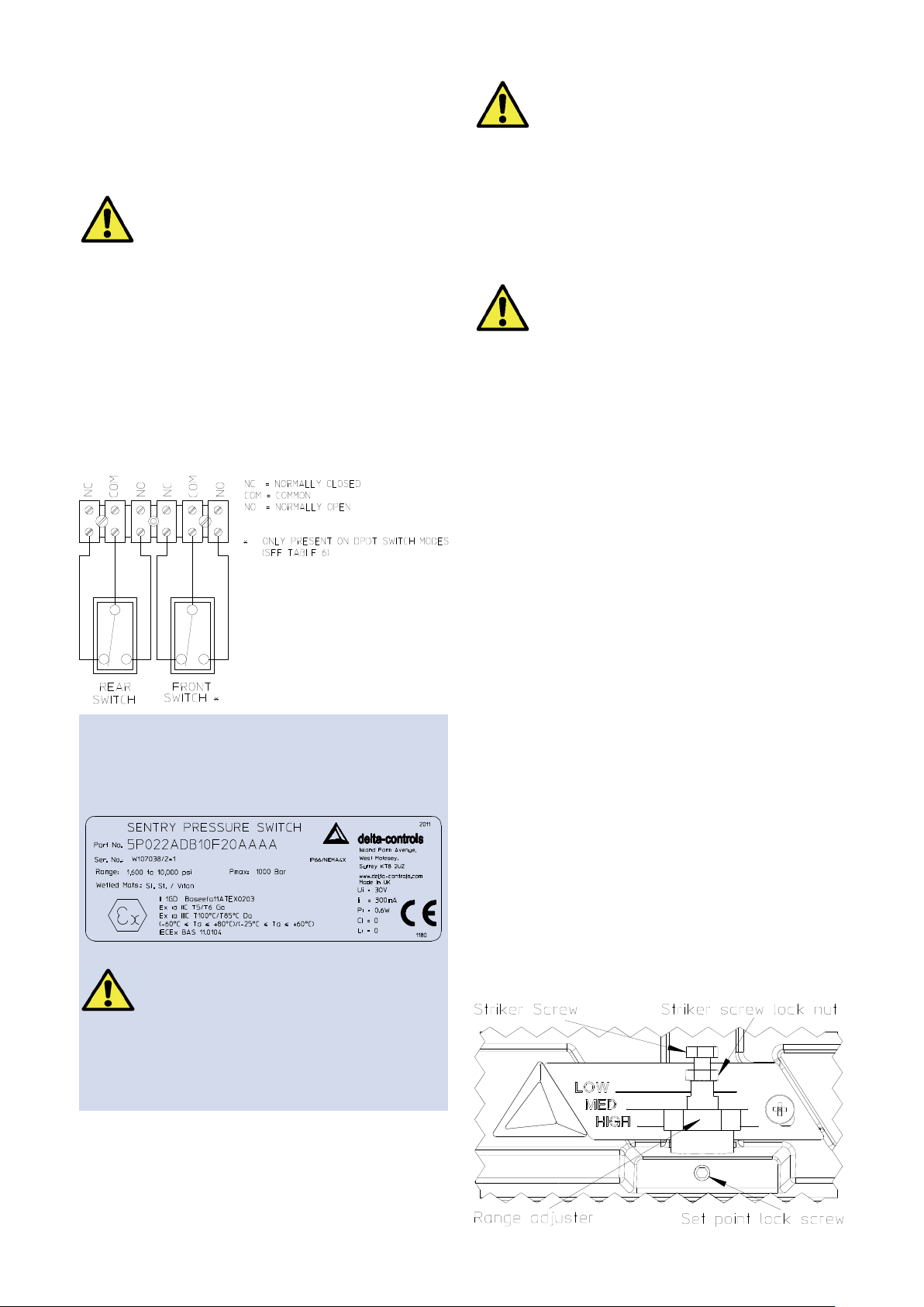
The three switch terminals are clearly marked
“NORMALLY CLOSED”, “NORMALLY OPEN” and
“COMMON”.
For products supplied with terminal blocks, the following diagram can be used as a guide for wiring.
BEFORE CLOSING THE LID:
Ÿ ENSURE WIRE IS CLEAR OF ALL
MOVING PARTS.
Ÿ CHECK THAT THE GASKET IS SEATED
CORRECTLY AND IN GOOD CONDITION
Ÿ ENSURE THAT WIRES DO NOT TOUCH
THE LID AS IT IS CLOSED
Close the lid, being careful not to trap any wires in
doing so. Tighten the lid locking screw until the lug on
the top of the lid makes contact with the enclosure lug.
THE LID LOCKING SCREW MUST BE
TIGHTENED FULLY IN ORDER THAT
ELECTRICAL CONNECTION IS MADE
BETWEEN THE LID AND THE ENCLOSURE
OPERATION
Adjustments
Pressure and Temperature Switches are supplied
calibrated at the midpoint of their range and to a falling
pressure or temperature unless otherwise specified.
To re-calibrate:
Notes for Intrinsic Safety
Input limitations for intrinsic safety:
Ui = 30V, Ii = 300mA, Pi = 0.6W
Example label:
THE MICRO SWITCHES MAY BE SINGLE OR
DOUBLE POLE, DOUBLE THROW
SWITCHES AND ALL THE ELECTRICAL
CONNECTIONS MUST FORM PART OF THE
SAME INTRINSICALLY SAFE CIRCUIT.
WHERE TWO MICRO SWITCHES ARE
FITTED, THEN ALL THE ELECTRICAL
CONNECTIONS MUST FORM PART OF THE
SAME INTRINSICALLY SAFE CIRCUIT.
1. Isolate the instrument from the process and power.
2. Loosen lid lock screw and open the lid.
3. Slacken the set point lock screw.
4. Using a suitable spanner, rotate the range
adjuster clockwise to increase the set point and
counter-clockwise to decrease the set point.
5. Tighten the set point lock screw.
6. Close the instrument lid and tighten lid lock screw
Note: For accurate setting of Pressure and Differential
Pressure models, a suitable pressure gauge must be
used in conjunction with the above procedure. Do not
attempt to set the switch outside the scale limits. For
Temperature models a suitable calibrated temperature
source should be used.
Though the unit may be set anywhere within its range,
for optimum performance, it is good practice to have a
set point value between 25% and 75% of span.
The striker screw and lock nut are factory set and
should not be adjusted. Should these parts be accidentally loosened, please contact Delta for assistance.
Insert bare wires fully into the terminal block and
tighten securely. Keep wiring tails to a minimum and
check that wires do not interfere with the operating
mechanism. Use the earthing / grounding points
provided.
www.delta-controls.com
Page 3

002522-SENTRY-C : FEB 2012
MAINTENANCE
Inspections should be carried out at quarterly to yearly intervals depending upon operating conditions. Isolate
the unit from process and power and remove the lid. Check all terminals for tightness. Check that cable tails
are not fouled or chafed. Check for internal condensation. Check that the gasket is seated properly in the lid
recess and is not worn. It is recommended that instruments used to provide an alarm are operated periodically
to ensure they are functioning correctly. If further maintenance is required seek advice from DELTA CONTROLS
before attempting repair or replacement of parts.
DIMENSIONS
Model Range DIM A DIM B DIM C
P02 / P03 ALL 187 - -
D01 BC 250 162 89
D02
D03
T01 / T02 ALL 187 - -
BD - CE 238 114 77
DC - EA 238 88 77
0D - 0E 263 192 102
DC - EA 263 166 102
www.delta-controls.com
Page 4
002522-SENTRY-C : FEB 2012
Declaration of Conformity
In accordance with EN ISO 17050-1:2004
We Delta Controls Ltd
of Island Farm Avenue, West Molesey, Surrey, KT8 2UZ, UK
in accordance with the following Directive(s)
2006/95/EC Low Voltage Directive
94/9/EC ATEX
hereby declare that:
Series Sentry
Models P01, P02, P03, D01, D02, D03, T01, T02
are in conformity with the applicable requirements of the following documents
for LVD
EN 60947-1:2007 Low-voltage switchgear and controlgear. General rules
EN 60947-5-1:2004 Specification for low-voltage switchgear and controlgear.
For ATEX
EN 60079-0:2009 Electrical apparatus for explosive gas atmospheres. General requirements
EN 60079-11:2007 Explosive atmospheres . Equipment protection by intrinsic safety "i"
EN 61241-11:2006 Electrical apparatus for use in the presence of combustible dust.
Protection by intrinsic safety "iD"
II 1G D Ex ia IIC T5 / T6 Ga
Ex ia IIIC T100°C / T85°C Da
(60°C≤Ta≤+80°C)/(25°C≤Ta≤+60°C)
Certified by BASEEFA, Notified Body No 1180 in accordance with Article 9 of Council Directive 94/9/EC
I hereby declare that the equipment named above has been designed to comply with the relevant sections
of the above referenced specifications. The unit complies with all applicable Essential Requirements
of the Directives.
Signed
Name: Ben Mellick
Position: Product Manager
On: 06 February, 2012
T+44 (0)20 8939 3500 F+44 (0)20 8783 1163 E sales@delta-controls.com W www.delta-controls.com
Delta Controls Limited
Island Farm Avenue, West Molesey, Surrey KT8 2UZ, UK.
www.delta-controls.com
Document Ref. No.
DC019 Issue C
Declaration of Conformity
Models: P02, P03, D02, D03, T02, T03
 Loading...