

Page 1
Quick Installation Guide for
SOLIVIA nano GW Gateway
Page 2
2
Risk of death by electrocution
Potentially fatal voltage is applied to the micro
inverter during operation. This potentially fatal
voltage is still present for ve minutes after all
power sources have been disconnected.
► Never open the Gateway.
► Use only the power cord delivered with the
Gateway. Check the power cord for damage
before usage.
► Never try to repair a damaged power cord.
► The Gateway can be operated safely and normally only
if installed and used in accordance with this manual (see
IEC 62109-5.3.3). Delta Energy Systems is not responsible
for physical injury and property damage incurred by failure
to observe the installation and operating instructions in this
manual. For this reason, be sure to observe and follow all
instructions!
► Install the micro inverters that shall be connected to this
Gateway according to the manual delivered with the micro
inverters.
► The Gateway communicates with the micro inverters via PLC
(Power Line Carrier). The communication quality depends on
the installation environment. The shorter the signal path, the
better the signal quality.
► In case multiple micro inverters are installed in parallel in a
three-phase system, a communication with the Gateway via
PLC is not possible.
► The Gateway is for indoor use only (protection degree IP20).
General Safety Instructions
2
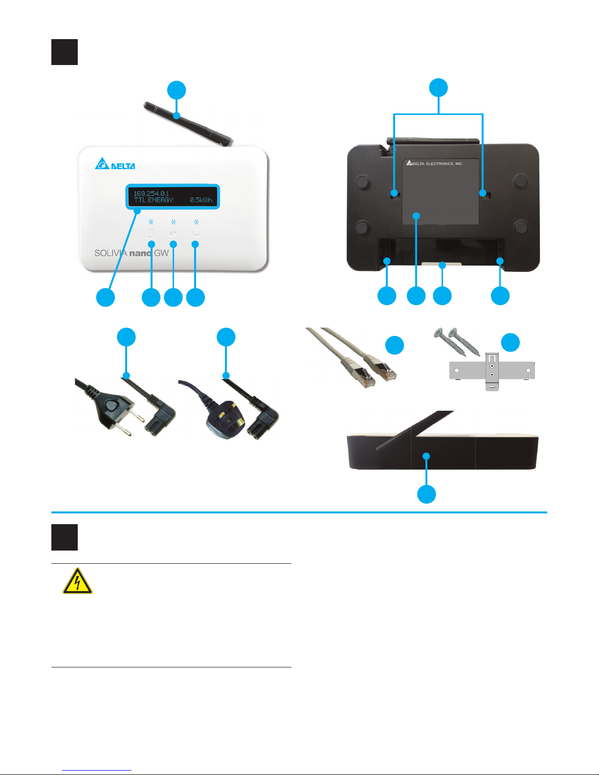
Components of the Gateway
1
12
3 4 52
1
14
7 109
6
8
11
13
15
Page 3
3
The Gateway is protection class II.
Do not put the Gateway into household waste.
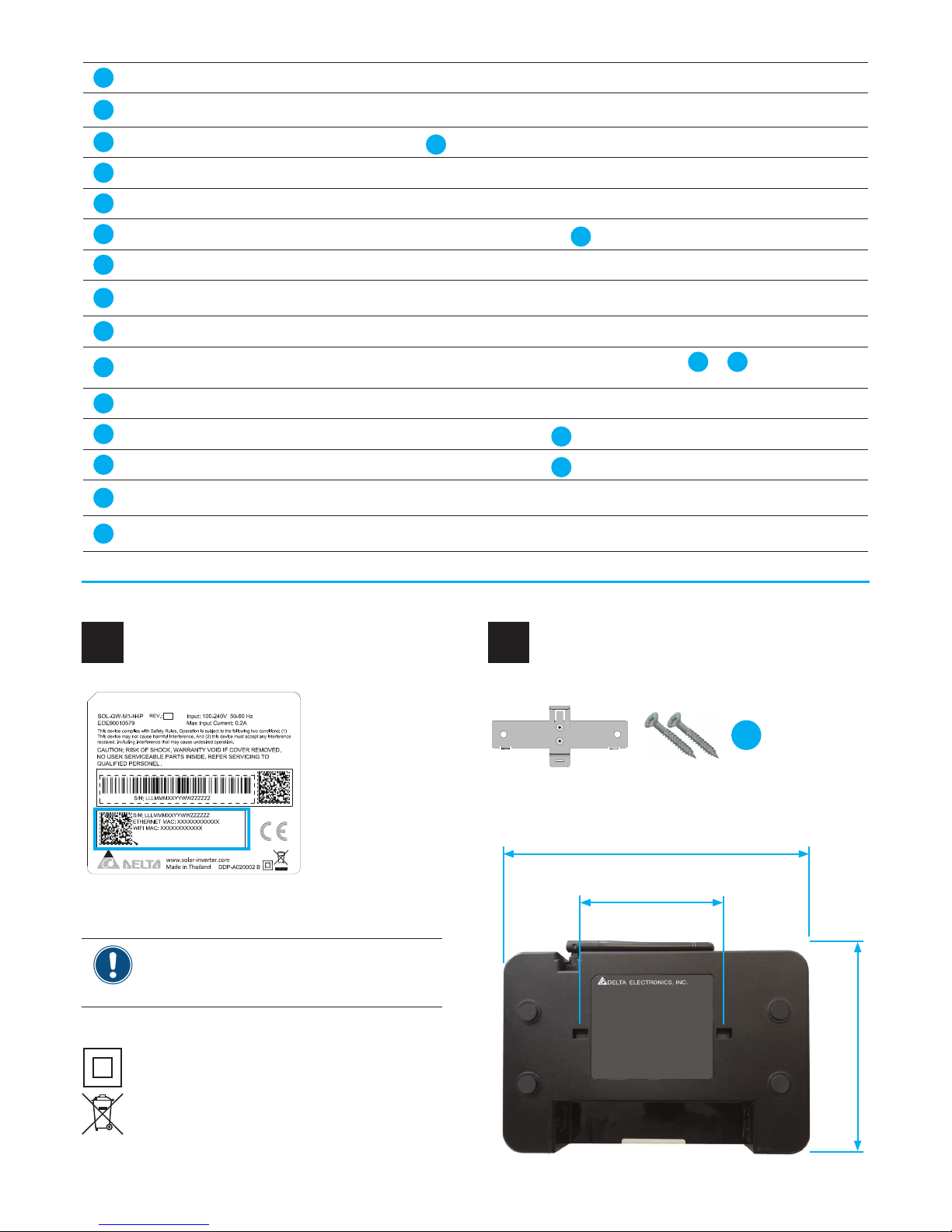
Type label
3
Mounting the Gateway
4
SOLIVIA nano GW
15
1
WLAN Antenna To connect the Gateway wirelessly (WiFi) to a local network or a PC.
2
Display To show the basic information for the Gateway.
3
MENU button
To awake the Display
2
from sleep mode and to enter the menu on the Display.
4
SCROLL button To move up and down in the menu and to set a parameter value.
5
ENTER button To nish parameter settings on the display.
6
Mounting holes
To mount the Gateway to the mounting bracket
15
.
7
Ethernet connector To connect the Gateway to a local network or PC.
8
Type label
Contains important information, e.g. the two MAC addresses which you need for SOLIVIA Monitor.
9
Warranty label Do not remove. Otherwise you will lose warranty.
10
Power connector
To provide the supply power for the Gateway. Via the Power cords
12
or 13, the Gateway com-
municates with the Micro inverters to get their data.
11
RESET button To return to default settings and restart the Gateway.
12
Power cord EU
To connect the Gateway to the Wall socket
18
in EU countries.
13
Power cord UK
To connect the Gateway to the Wall socket
18
in UK.
14
Ethernet cable RJ45
To connect the Gateway to a local network or PC. Not included in the box. Not needed when you
use WiFi.
15
Mounting bracket + 2 x
tapping screws
To mount the Gateway to the wall. Mounting bracket is in the box; screws are not. Use screws
appropriate for the type of wall.
Before you install the Gateway, write down the
two MAC addresses on the type label. You need
them to register your PV plant on SOLIVIA Monitor.
126.0 mm
80.0 mm
172.4 mm
Mounting bracket +
2 x Tapping screws
Page 4

4
Connecting the Gateway
6
16 17 18
7
Ethernet connector To connect the Gateway to a local network or PC.
10
Power connector
To provide the supply power for the Gateway. Via the Power cords
12
or 13, the Gateway com-
municates with the Micro inverters to get their data.
12
Power cord EU
To connect the Gateway to the Wall socket
18
in EU countries.
13
Power cord UK
To connect the Gateway to the Wall socket
18
in UK.
Communication options
5
The Gateway is used for two tasks:
(a) To set up and start the micro inverters (mandatory).
(b) To connect to the SOLIVIA Monitor Portal where you can
monitor your micro inverters (optional).
For both tasks, you need a PC with an internet browser. Wi-Fi
works with Windows XP / Vista / 7 and Mac OS X. To connect
to SOLIVIA Monitor, you need an internet connection (e.g. via a
router).
Ethernet cable
Ethernet selected
To use Gateway for task (a) only
Communication variant 1
WiFi (Ad-hoc)
WiFi selected
Communication variant 2
Keep the distance between PC and Gateway
small to have a good connection!
Page 5

5
12
13
12 14 1413
710
To use Gateway for task (a) + (b)
Ethernet cable
Ethernet selected
WiFi
Communication variant 3
WiFi
WiFiWiFi
WiFi selected
Ethernet cable
Communication variant 4
14
Ethernet cable RJ45
To connect the Gateway to a local network or PC. Not included in the box. Not needed when you
use WiFi.
16
Micro inverter(s) The Micro inverters installed in your PV system.
17
Distribution panel
Wall socket
18
and Micro inverters 16 are connected to the Distribution panel.
18
Wall socket
To provide the supply power for the Gateway. Also used for communication with the Micro inverters
16
.
You choose the connection type after rst power-up (see section 7, “ Setting up the Gateway”. You can
use either WiFi or Ethernet but not both at the same time. Once you have selected a communication type,
the other is disabled. To change your selection, press the Reset button
11
.
Page 6

6
Setting up the Gateway
7
> W i - F i D E V I C E
E T H E R N E T D E V I C E
4 5
FIRST POWER UP - CHOOSING CONNECTION TYPE
After powering up the Gateway for the rst time, you have to choose
the connection type:
● Wi-Fi device
● Ethernet device
See section 6 “Setting up communication” for explanation.
Use the SCROLL button
4
to choose the connection type. Press the
ENTER button
5
when nished.
> D I SPLA Y CONF I G
DEFAU LT D I S P . I N F0.
4 5
DISPLAY CONFIG
The display can be set so that it switches to power-save
mode when no button is pressed for some time.
Use the SCROLL button
4
to choose an option. Press
the ENTER button
5
when nished.
> # P0WER A LWAYS ON
POWER S AVE MO DE
4 5
D I SPLAY C ONF I G
> D EFAUL T D I SP . I NF0.
4 5
DEFAULT DISP. INFO.
You can choose which type of information is displayed:
● Produced power
● Operation status of micro inverters
Use the SCROLL button
4
to choose an option. Press
the ENTER button
5
when nished.
> # POWER D I SPLAY
STATU S D I SPLAY
4 5
Page 7

7
I N FO FO RM AT
> L ANGUA GE S
4 5
LANGUAGES
Here you can set the language for the display.
Use the SCROLL button
4
to choose an option. Press
the ENTER button
5
when nished.
> # ENGL I SH
DEUTS CH
4 5
> D ATE/T I M E S ETUP
EX I T MEN U
4 5
DATE/TIME SETUP
NOTE: If you use SOLIVIA Monitor, date and time are
set automatically by the portal server. Otherwise you
have to set date and time manually.
Use the SCROLL button
4
to choose an option. Press
the ENTER button
5
when nished.
> # DATE : 26 /0 5/1 4
T I ME : 13 : 5 9 : 17
4 5
> I NFO F OR MAT
LANGU AG ES
4 5
INFO FORMAT
You can choose whether the information set in
DEFAULT DISP. INFO. is shown for all micro inverters
together (TOTAL) or for each one individually.
Use the SCROLL button
4
to choose an option. Press
the ENTER button
5
when nished.
> # T0TAL
I N D I V I DUA L
4 5
Page 8

8
Conguring Communication on PC
8
Using WiFi (Communication variants 2 and 4)
1. On your PC, look for available wireless networks.
2. To connect to the Gateway, click on the wireless network with the name “DELTA_
xxxxxxxxxxxx” (The “xxx” stand for the WiFi MAC address of the Gateway - you can
nd it on the type label).
3. On your PC, open the Internet browser. In the address eld, type in the standard IP
address of the Gateway (with the dots): 169.254.0.1 and press the ENTER button on
your PC. It works like for a normal website.
→ The local website of the Gateway opens:
4. Now you can set up your micro inverters (see section 9, “Setting up and Starting
Micro Inverters”). If you nished with that, come back to this point.
→ If you don’t want to use SOLIVIA Monitor, conguration is now done and you can
disconnect your PC from the Gateway.
→ If you want to use SOLIVIA Monitor, continue with the next step.
To connect to your router, you need network name and network key of your router. Both you can
usually nd on its type label or in the documentation delivered with your router.
5. To search a wireless network (e.g. your router), click on Congure Network.
6. In the new window, click on the Scan Wireless Networks button.
7. In the list, click on the network name of your router.
→ A password dialog opens.
The communication variants mentioned in this section are described in section 5, “Setting up Communication”.
Page 9

9
8. Type in the network key of your router and click on OK button.
→ When the network key was correct, after a few seconds a new IP address and
the letters “DHCP” appear on the display of your Gateway. How the IP address
looks like, depends on your router.
172 . 25 . 16 . 1 33 DHCP
I D : 2 POWER : 0 . 0 W
9. Continue with section 10, “Connecting to SOLIVIA Monitor”.
Using Ethernet (Communication variant 1 and 3)
1. On your PC, open the Internet browser. In the address eld, type in the IP address
shown on the display of the Gateway (e. g. 169.254.0.1) and press the ENTER button on your PC. It works like for a normal website.
172 . 25 . 16 . 1 33 DHCP
I D : 2 POWER : 0 . 0 W
→ The local website of the Gateway opens:
2. Now you can set up your micro inverters (see section 9, “Setting up and Starting
Micro Inverters”). If you nished with that, come back to this point.
→ If you don’t want to use SOLIVIA Monitor, con guration is now done and you can
disconnect your PC from the Gateway.
→ If you want to use SOLIVIA Monitor, continue with section 10, “Connecting to
SOLIVIA Monitor”. ATTENTION: This works only with Communication Variant 3!
Page 10

10
Setting up and Starting the Micro Inverters
9
1. On the local website, click on Grid Settings. In the Country Set dropdown list,
select your country/grid. When done, click on the Submit button.
2. Click on Power Limitation. If your grid operator requires you to set a power limita-
tion or power factor, you can change the default settings. When done, click on the
Submit button.
3. Go to the Inverters section. Type in the serial number of each micro inverter con-
nected to the Gateway. You can nd the serial number on the type label of the micro
inverters. When nished, press the Save Setting button.
Page 11

11
Connecting to SOLIVIA Monitor
10
1. In the address eld of your Internet browser, type in the new IP address (which the
Gateway received from your router) and press the ENTER button on your PC.
2. Click on User Host Setting.
3. In the new window, you usually do not need to change the domain name “moni-
toringservices.solar-inverter.com”. So simply click on the Save Entered Address
button.
4. Click on User Register Page.
5. In the new window, read the Terms of Use and the Privacy Statement. Afterwards,
click on I have read and accept... and then click on the Connect to SOLIVIA Monitor button.
→ The Gateway connects to the SOLIVIA Monitor Portal. When the Gateway gets a
response, the following message is displayed in the Internet browser.
6. Now you can go to the SOLIVIA Monitor website and register your PV plant.
Open a new tab in your Internet browser and in the address eld, type in
monitoring.solar-inverter.com and follow the instructions on the website.
Page 12

Service Europe
© Copyright – Delta Energy Systems (Germany) GmbH – All rights reserved.
04.08.2014 - All information and specications can be modied without prior notice.
5017050000 00
Technical Data
Operation Input Voltage 90 ... 264 V
Nominal Input Voltage 100 / 240 V
Input Frequency Range 47 ... 63 Hz
Nominal Frequency 50 / 60 Hz
Maximum Input Power 3 W
Nominal Input Power 1.5 W
Operating temperature range -10 ... +40 °C
Storage temperature range -20 ... +60 °C
Relative humidity 5 ... 95%
Dimensions (W x H x D) 172.4 x 126.0 x 32.8 mm
Austria service.oesterreich@solar-inverter.com 0800 291 512 (call free)
Belgium support.belgium@solar-inverter.com 0800 711 35 (call free)
Bulgaria support.bulgaria@solar-inverter.com +421 42 4661 333
Czech Republic podpora.czechia@solar-inverter.com 800 143 047 (call free)
Denmark support.danmark@solar-inverter.com 8025 0986 (call free)
France support.france@solar-inverter.com 0800 919 816 (call free)
Germany service.deutschland@solar-inverter.com 0800 800 9323 (call free)
Greece support.greece@solar-inverter.com +49 7641 455 549
Israel supporto.israel@solar-inverter.com 800 787 920 (call free)
Italy supporto.italia@solar-inverter.com 800 787 920 (call free)
Netherlands ondersteuning.nederland@solar-inverter.com 0800 022 1104 (call free)
Portugal suporte.portugal@solar-inverter.com +49 7641 455 549
Slovakia / Poland podpora.slovensko@solar-inverter.com 0800 005 193 (call free)
Slovenia podpora.slovenija@solar-inverter.com +421 42 4661 333
Spain soporto.espana@solar-inverter.com 900 958 300 (call free)
Switzerland support.switzerland@solar-inverter.com 0800 838 173 (call free)
United Kingdom support.uk@solar-inverter.com 0800 051 4281 (call free)
Other European countries support.europe@solar-inverter.com +49 7641 455 549
 Loading...