

Page 1
Operation and installation manual for
SOLIVIA 2.5 EU G3
2.5
EU
Page 2

Page 3

1
ENGLISH
Operation and installation manual SOLIVIA 2.5 EU G3
The manual is subject to change.
Please check our website at www.solar-inverter.com
for the most up-to-date manual version.
© Copyright – Delta Energy Systems (Germany) GmbH - All rights reserved.
This manual accompanies our equipment for use by the end users.
The technical instructions and illustrations contained in this manual are to be treated as condential and no part may be reproduced without the prior written permission of Delta Energy Systems Service engineers and end users may not divulge the information
contained herein or use this manual for purposes other than those strictly connected with correct use of the equipment.
All information and specications are subject to change without notice.
Page 4

2 Operation and installation manual SOLIVIA 2.5 EU G3
Page 5

3
ENGLISH
Operation and installation manual SOLIVIA 2.5 EU G3
Table of Contents
1 Scope of delivery 4
2 General warnings / Notes on safety 4
3 Introduction 5
4 System 5
4.1 Data evaluation and communication 5
4.2 Technical structure of the solar inverter 6
4.3 Equipment overview 7
5 Installation 8
6 Installation of equipment 8
6.1 Installation location 8
6.2 Minimum requirements 8
6.3 Maintenance 9
6.4 Installation 9
6.5 Ambient temperature 10
6.6 Grid connection 10
6.7 Connection of PV modules 10
6.7.1 Output power over PV voltage 12
6.7.2 Output power over AC voltage 12
6.7.3 Efficiency 13
6.8 Interface connection RS485 (EIA485) 13
6.9 Electrical connection and operational start-up 15
6.10 Setup / settings 16
6.11 LED operation and fault display 17
7 Operating concept 18
7.1 The display 18
7.2 Navigation in the display 18
7.3 Main menu 18
7.3.1 Autotest (only for Italy) 20
7.3.2 Submenu N (Now) 23
7.3.3 Submenu D (Day) 23
7.3.4 Submenu W (Week) 24
7.3.5 Submenu M (Month) 24
7.3.6 Submenu Y (Year) 24
7.3.7 Submenu T (Total) 25
7.3.8 Submenu S (Setup) 25
7.3.8.1 Submenu S: Solar ISO / GND 26
7.3.8.2 Submenu S: Country settings 26
7.3.8.3 Submenu S: Firmware 27
8 Diagnostics and data evaluation 27
8.1 Malfunction rectification 27
8.2 Display messages 28
9 Technical data 30
10 Appendix 31
10.1 Connection examples 31
10.2 Overview of connection diagrams 32
11 Glossary 34
12 Guarantee 36
13 Certificates 381
Page 6
4 Operation and installation manual SOLIVIA 2.5 EU G3
1 Scope of delivery
• SOLAR INVERTER SOLIVIA 2.5 EU G3
• Mounting plate
• Operation and installation manual
• AC connector
2 General warnings / Notes on safety
Congratulations on the purchase of the technically advanced SOLAR INVERTER SOLIVIA 2.5 EU
G3.
These directions will help you become familiar with this product.
Please observe the safety regulations of the individual countries (e.g. for Germany: VDE, BDEW,
BGFE, technical connection conditions for local utility company). Careful handling of your product
will contribute to its service life durability and reliability. These are essential prerequisites for maximum yield from your product.
Please observe the following notes on safety:
• During operation of electrical devices, certain parts are under dangerous voltage.
• Inappropriate handling can lead to physical injury and material damage!
• Adhere to the installation regulations.
• Installation and operational start-up work may be implemented only through qualied electrical
experts.
• Repair work on the device should be carried out by the manufacturer only.
• Please observe all points in the operating and installation manual!
• Isolate the device from the grid and the PV modules before carrying out any work on it.
• As a result of very high temperatures, the device surface can become hot.
• Sufcient cooling is necessary.
• As the solar inverter is heavy (weight > 18 kg), it should be lifted by at least two persons.
• Remember that the unit has a high leakage current. The PE conductor MUST be connected prior
to commencing operation.
To avoid risk of electrical shock, do not open the solar inverter. The inverter
contains no user-serviceable parts. Opening the cover will invalidate the
warranty.
Dangerous voltage is present for 5 minutes after disconnecting all sources
of power.
Page 7

5
ENGLISH
Operation and installation manual SOLIVIA 2.5 EU G3
3 Introduction
With this device you have acquired a solar inverter for connection of photovoltaic systems to the
grid. This European solar inverter can be used in and is approved for the following countries:
Belgium, Czech Republic, France, Germany, Greece, Italy, Portugal, Spain and United Kingdom.
The solar inverter is characterized by its advanced housing design and state-of-the-art high-frequency technology, which enable the highest levels of efciency.
The solar inverter includes monitoring units, such as anti-islanding protection. The function of the
anti-islanding protection (automatic isolation point for in-plant generation systems) stipulates compliance with the specications of DIN VDE 0126-1-1, EN 50438, ENEL G.L., RD 1663, RD 661, UTE
15712-1, Synergrid C10/11 and G83/1-1, and compliance with the directives for parallel operation
of power generation plants on low-voltage grid of your local utility companies. These are declared
by certicates (see § 13).
The inverter is usable indoors and outdoors (IP65).
In the following technical description, the precise functions are explained to the installer, as well
as the user, which are required for the installation, operational start-up and handling of the solar
inverter.
4 System
The solar inverter converts direct current from the solar cells into alternating current. This enables
you to feed your self-produced solar energy into the public grid.
Thanks to efcient MPP tracking, maximum capacity utilization of the solar energy plant is ensured
even in the case of cloudy sky conditions.
The string concept means that PV modules are always connected in series (in a string) and/or that
strings with the same voltage are connected in parallel to the solar inverter with the aim of signicantly reducing the photovoltaic system’s cabling requirements.
The fact that the modules are connected in strings also means that the photovoltaic system can be
perfectly matched to the solar inverter’s input voltage range.
4.1 Data evaluation and communication
The integrated data display, processing and communication of the device enables easy operation of
the solar inverter. Monitoring of the operational status and signaling of operational failures are capable of being called up over the device display. The data interface enables the downloading of data
which can be evaluated with a PC system and guarantees continuous recording of operating data.
The best way of accessing this functionality is via the available accessories (e.g. WEB´log); comprehensive and seamless solar inverter monitoring is ensured.
The data read-out over the integrated interface and the display is possible only in solar operation.
Page 8

6 Operation and installation manual SOLIVIA 2.5 EU G3
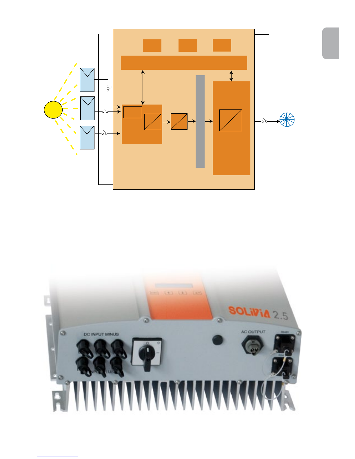
4.2 Technical structure of the solar inverter
A galvanical isolation of the solar inverter from the grid is achieved through a DC/AC converter with
an integrated high-frequency transformer. The photovoltaic voltage is adjusted so that the maximum
power output of the PV modules is also achieved with varying solar irradiation levels and temperatures (MPP-Tracking).
The MPP range of the solar inverter is between 150 V and 450 V. This facilitates the use of PV
modules by a variety of manufacturers. Measures must be taken to ensure that the maximum opencircuit voltage of 540 VDC is never exceeded. Please note that the maximum open-circuit voltage
will occur at the lowest temperatures anticipated. You will nd more detailed information about
temperature dependency in the data sheet of the PV modules. The device’s power consumption is
kept to a minimum.
The high-quality aluminum casing corresponds to protection class IP65 (water-jet-proof and dustproof) and is protected against weathering processes by surface re nement. The cooling characteristic pro le is designed so that operation of the inverter is possible with ambient temperatures
from -25°C to +70°C.
A cooling characteristic pro le is used for the removal of the power dissipation caused through the
voltage conversion. An internal temperature control protects the device against excessive temperatures in the interior of the solar inverter. In case of high ambient temperatures, the maximum
transferable power is limited.
The solar inverter is controlled by microcontrollers, which also implement interface communication
and the monitoring of values and messages on the display.
Two independent and redundant microcontrollers control the monitoring of the grid, which is consistent with the feed-in directives of your local utility company and DIN VDE 0126-1-1, EN 50438,
ENEL G.L., RD 1663, RD661, UTE 15712-1, Synergrid C10/11 and G83/1-1 (anti-islanding protection). This enables an installation of the solar inverter in the in-house electrical grid.
Operator protection requirements are met by electrically isolating the grid from the PV module. The
electrical isolation between the grid and the PV module is equivalent to basic insulation. Maximum
operator protection is ensured by reinforced isolation between the grid, PV modules and accessible
interfaces (display and RS485 interface). Relevant standards concerning electromagnetic compatibility (EMC) and safety are ful lled.
The solar inverter is functional in on-grid operation exclusively. An automated isolation point, which
is approved by a certi cation agency, guarantees secure disconnection in case of circuit isolation or
interruptions in power supply and avoids isolated operation.
The disconnection equipment allows for automatic isolation for in-plant generation systems of nominal power ≤ 4.6 kVA, with single-phase parallel feed-in through the solar inverter into the public grid.
Page 9
7
ENGLISH
Operation and installation manual SOLIVIA 2.5 EU G3
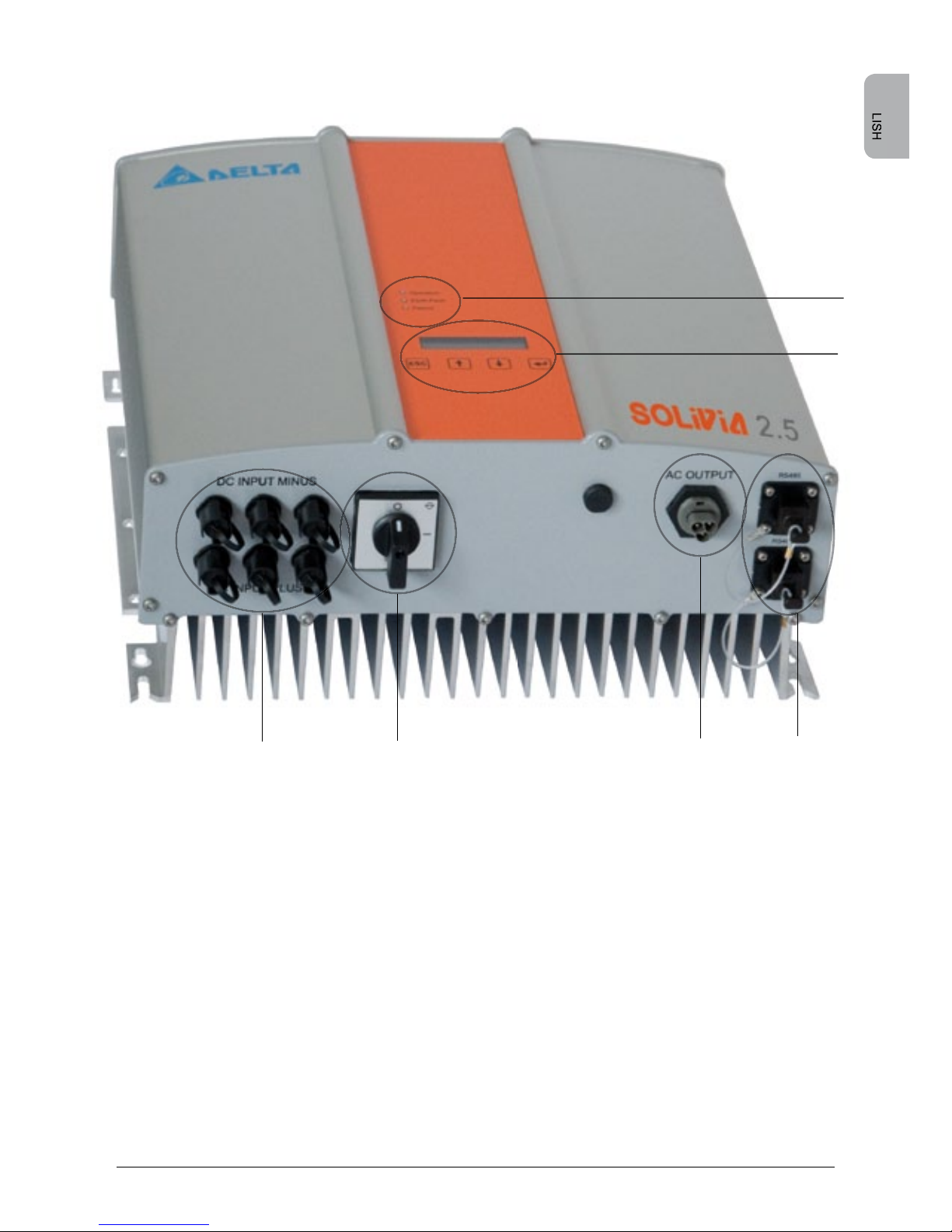
4.3 Equipment overview
(1) Connections for solar modules
(2) DC disconnector
(3) Grid connection
(4) Interface connection RS485 (EIA485)
(5) Display for status messages and keypad for operation
(6) Light-emitting diodes for operational status display
ENGLISH
(1)
(2)
(3)
(5)
(6)
(4)
Page 10

8 Operation and installation manual SOLIVIA 2.5 EU G3
5 Installation
Installation and commissioning must only be carried out by qualied electrical experts.
The recommended safety regulations, the technical interface conditions (TAB 2000), as well as
DIN VDE 0126-1-1, EN 50438, ENEL G.L., RD 1663, RD661, UTE 15712-1, Synergrid C10/11 and
G83/1-1 specications, should be complied with.
When the grid is DE LVD: According to VDE AR N 4105, the installed capacity of the PV generator
must not be greater than 3.68 kW.
To carry out an energy measurement, a meter must be attached between the grid feed-in point
and the solar inverter (in accordance with your local utility company directive concerning „In-plant
generation systems on the low-voltage grid“).
By means of the integrated anti-islanding protection, the function of the recommended section
switch is fullled in accordance with your local utility company directive.
Caution: The secondary short-circuit current rating is increased at the transfer connection point to
the public electricity supply system by the nominal current of the connected solar inverter.
6 Installation of equipment
6.1 Installation location
• Install the device on a non-ammable support base.
• Avoid installation on resonating bodies (light construction walls etc.).
• Installation is possible both indoors and in protected outdoor areas.
• An increased ambient temperature can reduce the efciency of the PV system.
• Noise generation is possible (avoid installation in residential areas).
• Ensure legibility of the LEDs and the display (check read-off angle and installation height).
• Although the unit is tted with UV resistant components, direct exposure to sunlight should be
avoided.
• Despite having an IP65 enclosure and being certied in accordance with soiling category III, the
unit must not be allowed to become heavily soiled.
• Dusty conditions soiling can impair the unit’s performance.
6.2 Minimum requirements
• Free convection around the solar inverter must not be impaired.
• For proper air circulation to dissipate heat, allow a clearance of approx. 10 cm to the side and
approx. 50 cm above and below the unit.
• The grid impedance requirement at the supply terminal is to be observed (cable length, cable
cross-section).
• The recommended installation position is to be adhered to (vertical).
• Unused DC connectors (Tyco) and interfaces must be sealed airtight with sealing plugs to en sure protection class IP65 for the whole system (inverter & cables).
Page 11
9
ENGLISH
Operation and installation manual SOLIVIA 2.5 EU G3
319.5
150
320
200
6.5
12
Ø
12.5
90
38
12
410 ± 0.5
6.3 Maintenance
Make sure that the device remains uncovered while in operation. To avoid the casing of the solar
inverter becoming soiled, it should be cleaned periodically.
User-serviceable parts are not contained in the device. Under no circumstances should the solar
inverter be opened!
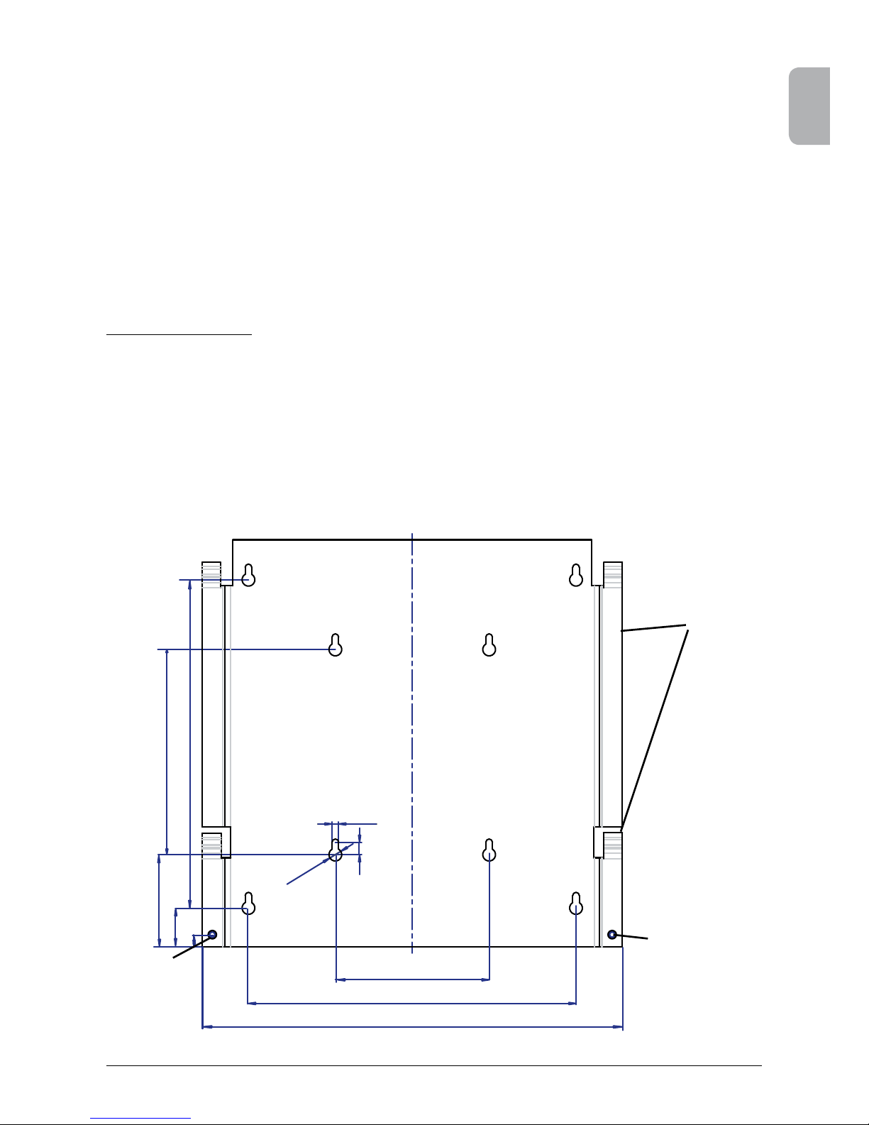
6.4 Installation
You should utilize the delivered mounting plate for problem-free installation of the solar inverter.
Installation to the wall should be implemented with the proper screws. Mount the wall bracket so
that the solar inverter can be easily attached to the wall. After that, the device should be bolted on
securely.
Assembly instructions
1. Mount the mounting plate with appropriate screws (max. Ø 6mm) into at least four of
the eight holes to x the wall bracket in place. You can employ the mounting plate as a
template for marking the positions of the boreholes.
2. As the solar inverter weighs 21.5 kg, it should be lifted out of the transport crate by at
least two persons.
3. Place the solar inverter onto the mounting plate with at least two persons.
4. Fasten the supplied mounting nuts and washers on the threaded bolt intended for secu ring the device.
5. Check that the solar inverter is securely seated.
Mounting
plate
Locking screw
Locking screw
Page 12

10 Operation and installation manual SOLIVIA 2.5 EU G3
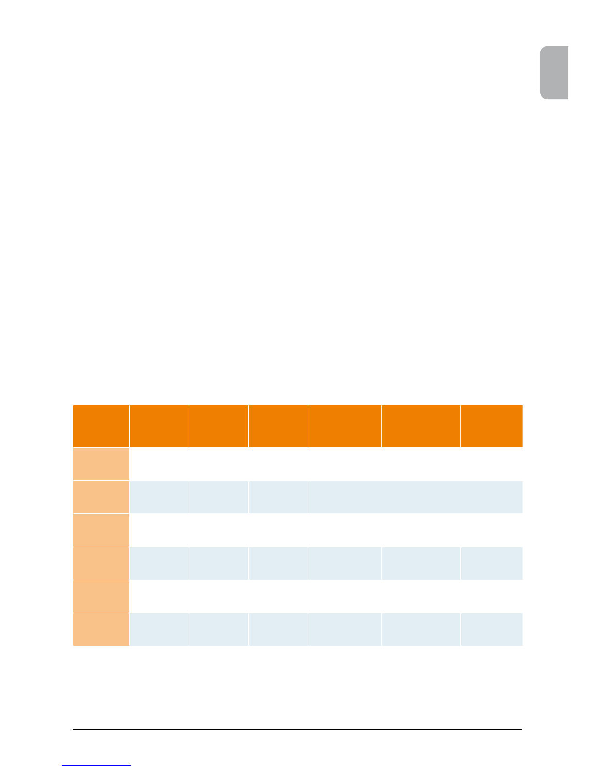
6.5 Ambient temperature
The solar inverter can be operated in an ambient temperature between -25°C to +70°C.
The following diagram illustrates how the power supplied by the solar inverter is reduced automatically in accordance with ambient temperature.
The device should be installed in a well-ventilated, cool and dry location.
6.6 Grid connection
The grid (AC output) is connected over a Wieland RST25i3S AC connector. You can nd the correct allocation on the screw-type terminal connection of the connector. The solar inverter must be
connected to the grid over a three-core line (L, N, PE). The connected AC line must be switched
potential-free before the disconnection or the insertion of the AC connector.
The connection to the Wieland AC connector must be made with a exible line and a conductor
cross section of min. 2.5 mm² to max. 4.0 mm².
An automatic circuit breaker is to be provided in the line L upstream of every device, with a nominal
current of 16 A and tripping characteristic type B. In addition, attention is to be paid to the selectivity
of the fuse unit attached upstream of the automatic circuit breaker.
The solar inverter must be grounded via the AC connector’s PE conductor. To do this, connect the
PE conductor to the designated terminal. If you wish to integrate more than one inverter into the
installation, please proceed as illustrated in the drawings in the appendix.
Please note the cable length and the cable cross-section, due to the risk of undesirable temperature
rise and power losses.
The AC connector is protected from unintentional disconnection by a clip mechanism which can be
released with a screwdriver.
6.7 Connection of PV modules
Before the photovoltaic system is connected, the polarity of the PV voltage at the Tyco connectors
must be checked to ensure that it is correct.
The connection of the PV module is implemented using Tyco Solarlok connectors, where the DC
negative pole is located on the connector upper row and the DC positive pole on the connector
lower row. The connectors are coded to prevent you from accidentally plugging them into the wrong
terminal.
Please ensure the following at all times:
• That there is never any risk of anyone coming into contact with the solar inverter connection
terminals, due to the risk of dangerous voltages across them.
• That under no circumstances are the PV modules to be disconnected from the solar inverter under
load. If a disconnection should be necessary, rst switch the grid off so that the solar inverter
cannot absorb any further power. Next, open the upstream DC disconnector.
The maximum input voltage of the solar inverter is 540 V. The maximum current load of each individual Tyco connector is 18 A.
Page 13
11
ENGLISH
Operation and installation manual SOLIVIA 2.5 EU G3
The solar inverter has an insulation and grounding monitoring on the DC side. The options can be
congured in the Setup menu “S -> Solar ISO / GND” (see § 7.3.8.1).
The insulation monitoring has two modes:
• ISO-ON-Error (the solar inverter is disconnected from the grid in the event of an insulation
fault)
• ISO-ON-Warning (the solar inverter indicates the fault but is not disconnected from the grid).
Deltas solar inverters are factory-set to ISO-ON-Warning mode on delivery.
The grounding monitoring has two modes:
• PV+ grounding (grounding monitoring of the positive pole of the PV generator)
• PV- grounding (grounding monitoring of the negative pole of the PV generator).
In these modes the solar inverter remains in feed-in operation and will not be disconnected from the
grid in case of a fault. The error message “PV+ grounding fault” or “PV- grounding fault” will appear
on the display.
If you need to connect the positive or negative pole of the PV system to meet requirements set
out by the module manufacturer, you can do this. Earth continuity must be implemented close to
the inverter. We suggest using Deltas grounding kit “Grounding Set A Solar” (EOE 99000115). The
grounding connection is monitored and should be congured in the Setup menu (see above).
Alternatively, it is possible to turn off the insulation- and grounding monitoring:
• ISO / GND OFF.
Required cable coupler types for DC cable connection to inverter:
CABLE
COUPLER
POLARITY
WIRE SIZE
2.5 MM
2
(AWG 14)
WIRE SIZE
4.0 MM
2
(AWG 12)
WIRE SIZE
6.0 MM
2
(AWG 10)
FEMALE CABLE COUPLER
PLUS CODED
FEMALE CABLE
COUPLER
MINUS CODED
TYCO
ORDER
NUMBER
Plus
coupler
• •
1394462-1
Minus
coupler
• •
1394462-2
Plus
coupler
• •
1394462-3
Minus
coupler
• •
1394462-4
Plus
coupler
• •
1394462-5
Minus
coupler
• •
1394462-6
Page 14
12 Operation and installation manual SOLIVIA 2.5 EU G3
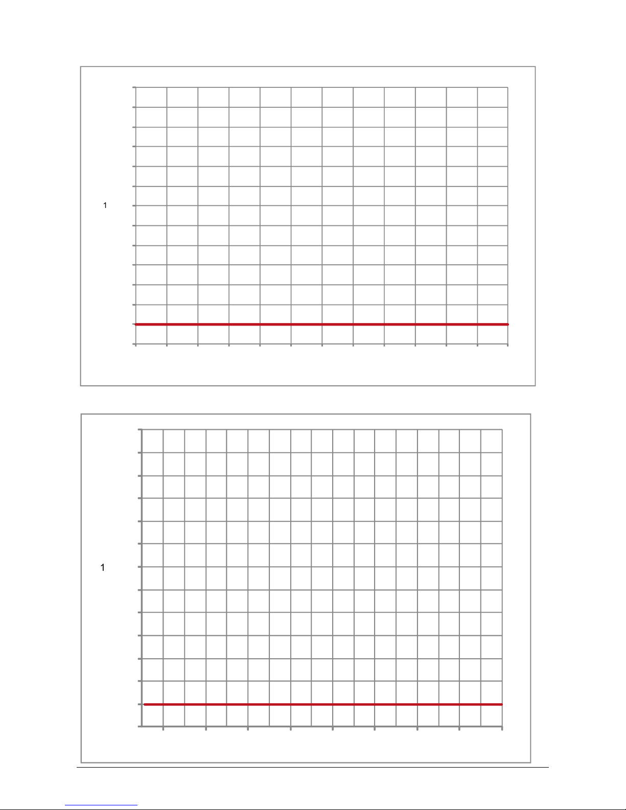
6.7.1 Output power over PV voltage
150 VDC
200 VDC 250 VDC
300 VDC
350 VDC 400 VDC 450 VDC
500
2
7
0
0
W
2
900
W
3
W
W
6.7.2 Output power over AC voltage
W
W
W
W
W
210 VAC 230 VAC 250 VAC
270 VAC
Page 15
13
ENGLISH
Operation and installation manual SOLIVIA 2.5 EU G3
6.8 Interface connection RS485 (EIA485)
The interfaces not used must always be closed off. In case of utilization of an interface, only the
counterpart tting on the interface connector is to be employed.
Mating connector supplier HARTING Deutschland GmbH & Co. KG (P.O. 2451, D-32381 Minden;
www.harting.com).
Order designation: 09 45 145 1510, Cable Manager Blue IP67 Push-Pull Data Plug
09 45 145 1500, Cable Manager White IP67 Push-Pull Data Plug
-
~
-
~
-
~
-
~
230 V - House connection line
RS485 (EIA485) - Connection
Datalogger
RS485 (EIA485)
terminating resistor
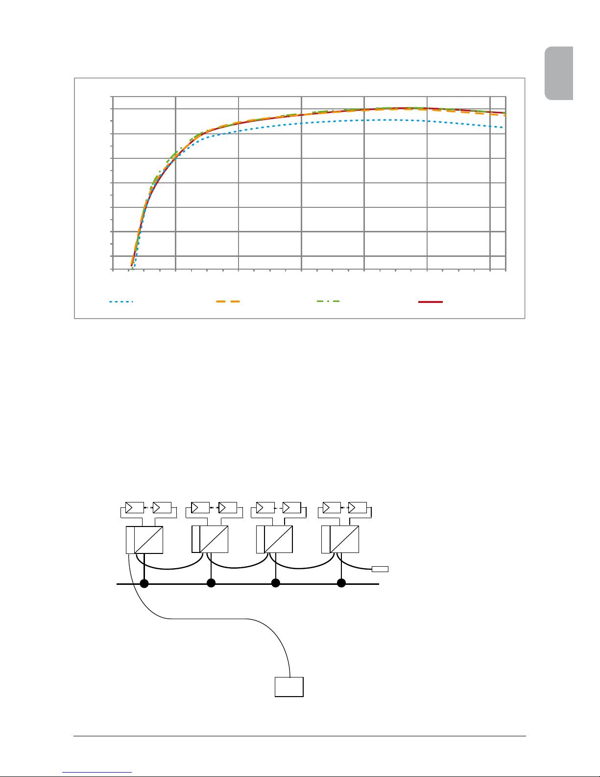
6.7.3 Efciency
The best efciency of the solar inverter is obtained at input voltages >250 V.
84 %
86 %
88 %
90 %
92 %
94 %
96 %
0 W
400 W
800 W
1200 W
1600 W
2000 W
2400 W
2500 W @ 150 V
2500 W @ 250 V
2500 W @ 350 V
2500 W @ 450 V
Page 16
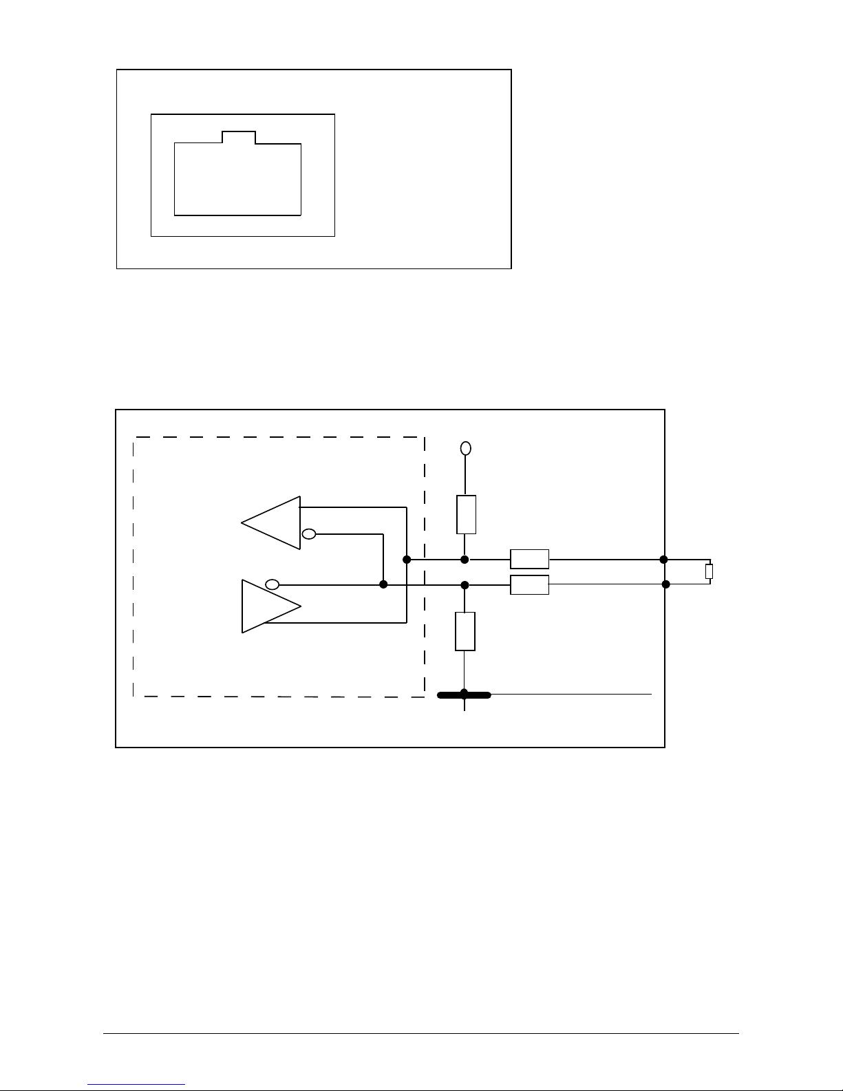
14 Operation and installation manual SOLIVIA 2.5 EU G3
8
1
Pin
1 Reserved
2 Reserved
3 Reserved
4 GND (RS485)
5 Reserved
6 RX_B (RS485)
7 TX_A (RS485)
8 Reserved
Top View
Connector pin assignment RS485 (EIA485)
+5V
Reserved
Reserved
0R
0R
TX_A
RX_B
GND
Pin 7
Pin 6
100 ... 150
Ohm, 0,25W
When several devices are connected in series and the total length of the data line measures 2 m or
more, the following option is available for terminating the RS485 (EIA485) interface:
Page 17
15
ENGLISH
Operation and installation manual SOLIVIA 2.5 EU G3
6.9 Electrical connection and operational start-up
The electrical connections are utilized on this solar inverter using the connector contacts which are
attached to the casing. Under no circumstances should the device be opened!
Power
controller
Antiislanding
protection
Communication
Operating- and system control
MPPTracker
-
-
Booster
-
-
Isolation
DC-Bus
~
Solar inverter
DC
DC
DC
String A
String B
String C
AC
Public
grid
Page 18
16 Operation and installation manual SOLIVIA 2.5 EU G3
In order to set up the device, follow these procedures carefully:
1. Turn off the DC disconnector.
2. DC connection: First, connect the PV module strings to the DC Tyco Solarlok connectors (ensure
correct polarity).
3. AC connection: Please install the Wieland AC mating connector to the AC output cable and then
plug the AC connector to the solar inverter. Please make sure, that the sleeve nut is properly
xed and tighten.
4. Before switching on the power, check all feeders and connections one last time.
5. Turn on the DC disconnector.
6. Close the circuit breaker on the AC output side.
7. In case of sufcient PV voltage (UPV > 150 V), the device now goes into the feed-in operation.
8. In case of a new installation the time and date have to be set in sub-menu S (Setup) (see § 7.3.8).
All unoccupied connectors and interfaces must be sealed using the provided sealing
plugs.
6.10 Setup / settings
The default display language for solar inverters leaving the Delta factory is set to English.
After connecting to correct DC voltage and running through self-test, you will be asked to specify
the network ID and to select the desired country (see § 7.3.8.2) (countries available: Belgium,
Czech Republic, France, Germany, Greece, Italy, Portugal, Spain and United Kingdom).
The selection has to be conrmed another time by the user. Once conrmed, the network ID and
the country selection are stored to the controller memory – and the solar inverter is ready for
operation.
A power limitation can be set for the AC side (50% .. 100% of maximum power). Note: When you
set a power limitation during installation, ll out the label "This product has been power limited by
internal software setting at: " with a water-proof pen and attach it at the front of the inverter. The
set value is also displayed in the Setup menu (see § 7.3.8.2).
The display buttons will be locked, if there is no input entry within 5 minutes. To unlock the enter
keys, you need to switch off the DC voltage and then switch it on again.
Page 19
17
ENGLISH
Operation and installation manual SOLIVIA 2.5 EU G3
Country selection
Increase network ID Decrease network ID
Down *
Up *
Enter network ID
ENTER *
ESC *
Select country
Next country Country before
Down *Up *
ENTER *
Normal mode
* Timeout if no key is pressed (within 5 minutes)
Possible countries:
Belgium
Czech Republic
France
French island (60 Hz)
DE VDE
DE LVD
Greece continent
Greece island
Italy (50 Hz / 49 Hz)
Italy (51 Hz / 49 Hz)
Portugal
Spain (51 Hz / 49 Hz)
Spain (51 Hz / 48 Hz)
United Kingdom
AC Pwrlim [W]
3456 W
Set AC Pwrlim. ?
YES | NO
ENTER *
YES
NO
ESC *
ESC *
Please note, that once the country has been selected and con rmed, it is only possible to change
the country by following the steps as listed below:
1. Please click ESC + Down button for few seconds to get the key information.
2. Provide the key code to the Solar Support Team at support@solar-inverter.com to get the PIN
code (valid for one use only!).
3. Once you get the PIN code, you need to press ESC + Down button.
4. Then, you will be asked to insert the PIN code and to con rm it twice.
5. After con rmation, you will then be able to select the desired country.
Note: These steps must be executed without interruption. Otherwise, you will stay in the country
selection mode.
Page 20
18 Operation and installation manual SOLIVIA 2.5 EU G3
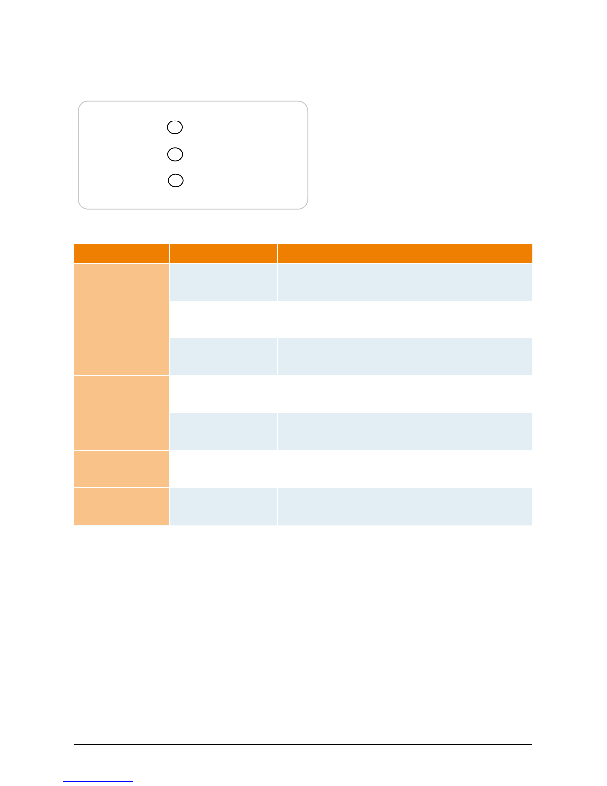
Operation (A)
Earth Fault (B)
Failure (C)
• LED (A), green: „Operation“ displays the
operational state.
• LED (B), red: „Earth Fault“ displays an insula tion resistance fault or PV grounding (GND)
fault on the DC side.
• LED (C), yellow: „Failure“ displays existing
faults internally or externally and whether the
grid feed-in operation has been interrupted.
6.11 LED operation and fault display
Three light-emitting diodes (LEDs), which display the operational state of the solar inverter, are attached on the front:
LED STATUS OPERATIONAL STATE EXPLANATION
green: <off>
red: <off>
yellow: <off>
Night disconnection.
The input voltage (UPV) is lower than 100 V.
The solar inverter is not feeding power to the grid.
green: <on>
red: <on>
yellow: <on>
Initialization.
Input voltages:
UPV: 100 V to 150 V
(self test ongoing).
green: <ashes>
red: <off>
yellow: <off>
Input- and grid monitoring.
Starting conditions are tested.
green: <on>
red: <off>
yellow: <off>
Feed-in operation.
Normal operational state:
UPV: 150 V to 450 V.
green: <off>
red: <on/off>
yellow: <on/off>
Equipment fault.
Internal or external fault
(interrupted feed).
See also display messages!
green: <off>
red: <on/off>
yellow: <on>
General error
condition.
Solar inverter is not connected to the grid.
No power is delivered.
See also display messages!
green: <on/off>
red: <on/off>
yellow: <ashes>
Warning message.
You can carry on using the solar inverter.
See also display messages!
Page 21
19
ENGLISH
Operation and installation manual SOLIVIA 2.5 EU G3
7 Operating concept
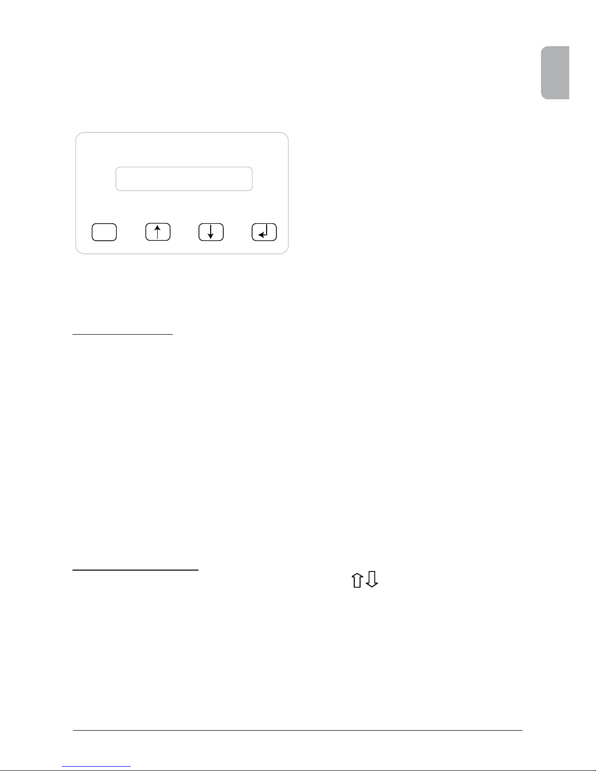
7.1 The display
The display on the device indicates varied information. The enter keys are used for the adjustment
of the device and for the retrieval of information. The measured data can deviate with a tolerance
of up to 5%.
ESC
(A) (B) (C) (D)
7.2 Navigation in the display
Lighting of the display
After pressing the ENTER key in automatic operation, the display lighting is switched on. If no key
is pressed within 30 seconds, the display lighting automatically goes out. The setup menu enables
selection between continuous or automatic lighting. Through pressing the ENTER key, the display
lighting is switched on again.
Key (A), ESC: To switch from the menu
items to the main menu and
to exit each sub-menu.
Key (B) and (C): For scrolling in the individual
menu items and/or carrying
out adjustments in the setup
menu.
Key (D), ENTER: ENTER key for changing into
the menu levels and for input
acknowledgement in the
setup menu.
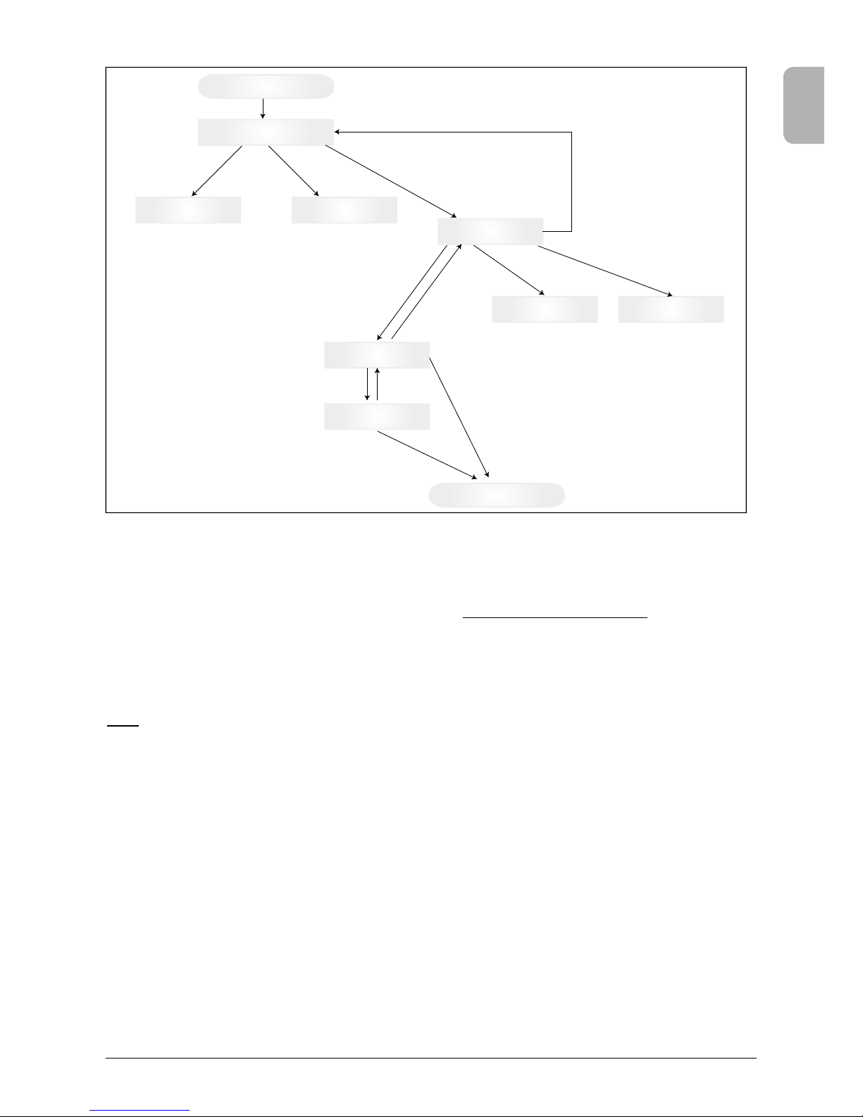
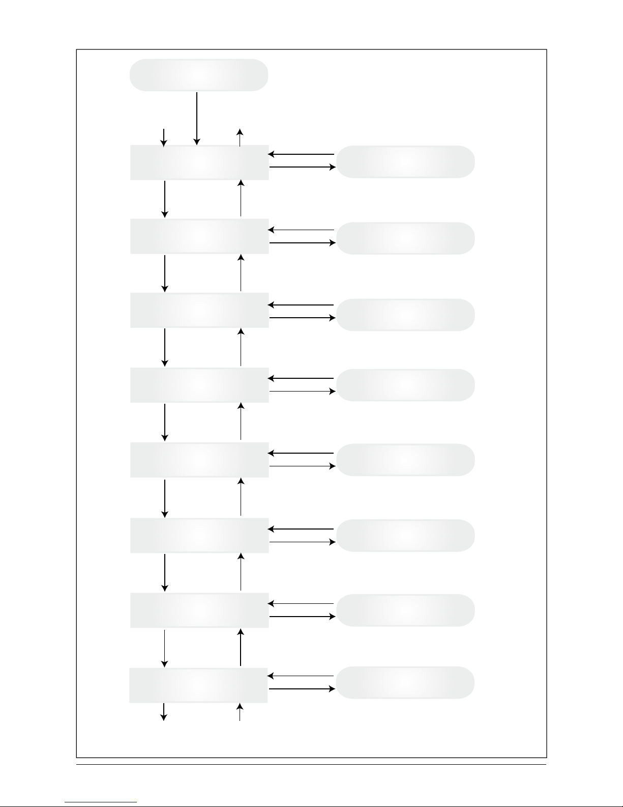
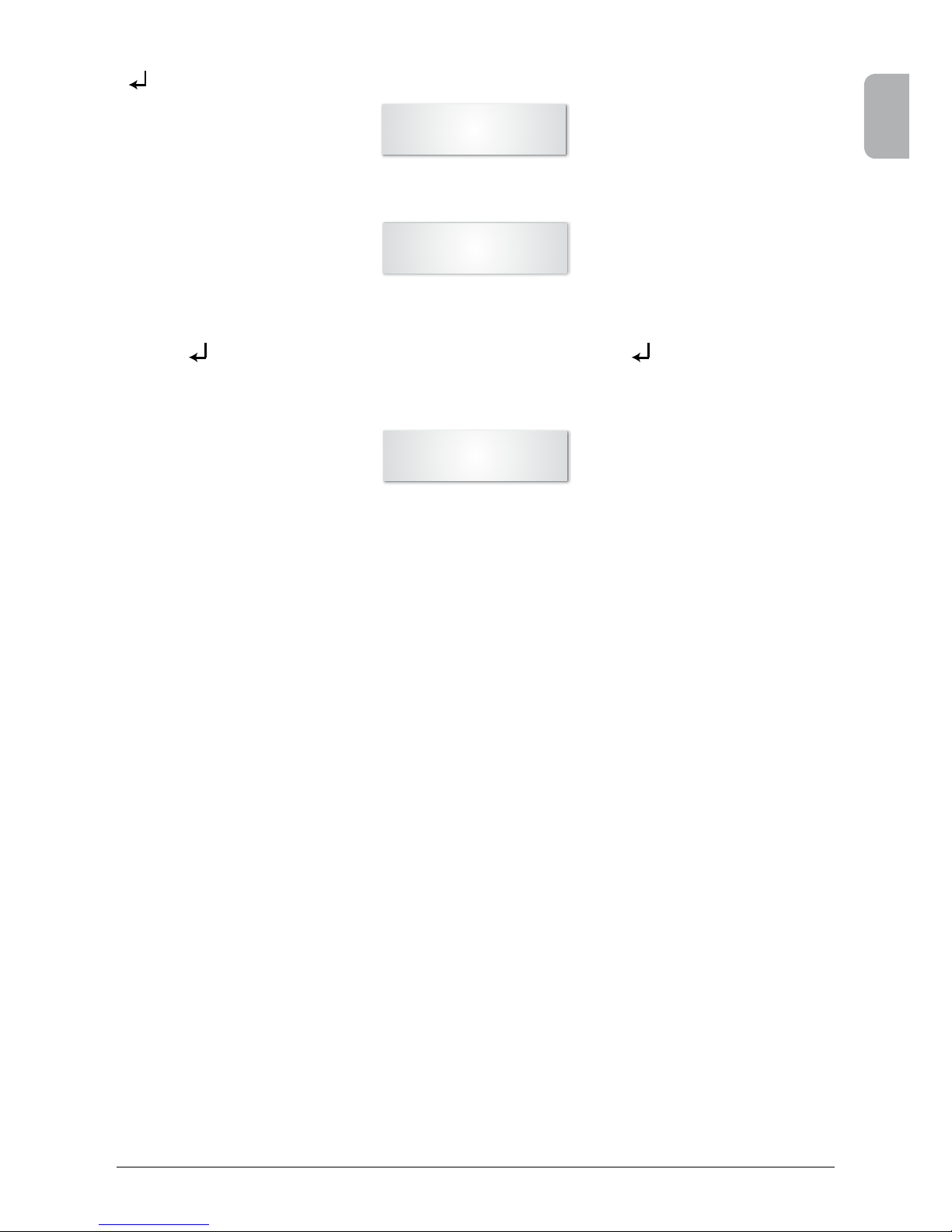
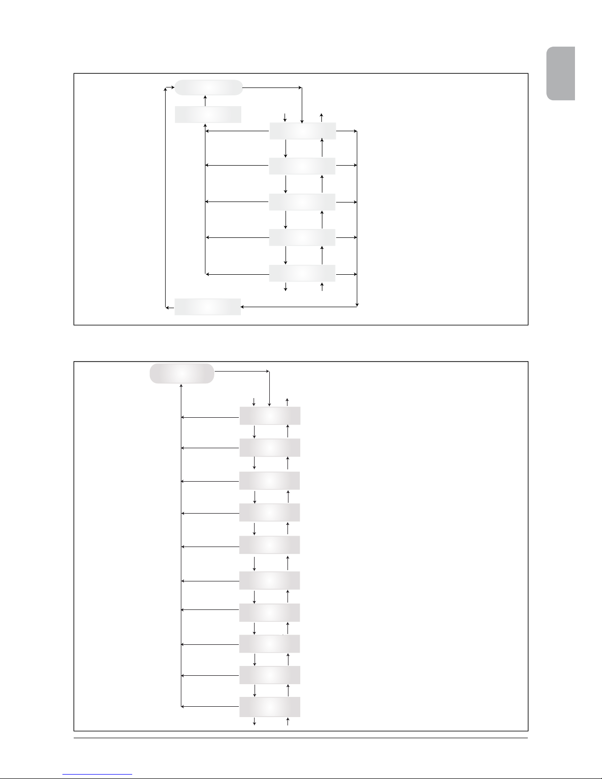
7.3 Main menu
The main menu consists of 8 menu items which are subdivided into submenus:
• Menu Autotest
• Menu N (Now)
• Menu D (Day)
• Menu W (Week)
• Menu M (Month)
• Menu Y (Year)
• Menu T (Total)
• Menu S (Setup)
Handling of the menu items:
You can scroll the main menu by activating the selector keys
.
Press the ENTER key to select the submenus. In order to exit the menus again, activate the ESC
key.
Page 22
20 Operation and installation manual SOLIVIA 2.5 EU G3
User menu
Down to 2
1
Up to 1
2
Remarks:
ESC in main menu jumps to first entry of
corresponding sub menu
Menu Autotest
(only for Italy)
Down
Up
Submenu Autotest
ESC
ENTER
Menu-N
Now (act. Data)
Menu-D
Day Statistic
Menu-W
Week Statistic
Menu-M
Month Statistic
Menu-Y
Year Statistic
Menu-T
Total Statistic
Menu-S
Setup Inverter
Down
Down
Down
Down
Down
Down
Up
Up
Up
Up
Up
Up
Submenu N - Now
Submenu D - Day
Submenu W - Week
Submenu M - Month
Submenu Y - Year
Submenu T - Total
Submenu S - Setup
ESC
ESC
ESC
ESC
ESC
ESC
ESC
ENTER
ENTER
ENTER
ENTER
ENTER
ENTER
ENTER
Page 23
21
ENGLISH
Operation and installation manual SOLIVIA 2.5 EU G3
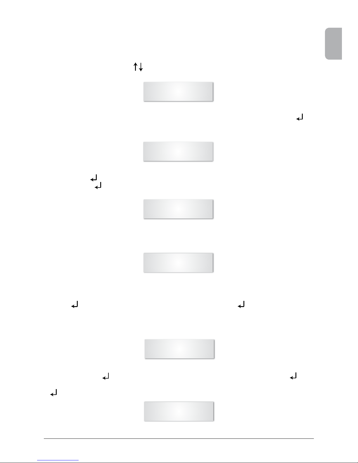
Autotest Passed
Start Autotest?
The rst line shows the actual autotest status which could be „passed” or „failed”. Pressing the
autotest routine starts. The rst test performed is the OVT, over voltage test, which verify the over
voltage protection. The display shows:
7.3.1 Autotest (only for Italy)
This function is available only for the Italian country.
The inverter is supplied with an autotest function able to verify the correct operation of the interface
protection.
In the main menu, using buttons , select the autotest menu. The display shows, for example:
L: 262 V < 0.1 S
Start OVT test?
The rst line shows the actual over voltage limit and detection time settings according to the standards. Pressing the test starts. Pressing „ESC” the display goes back to the main menu. Test
starts by pressing or automatically after 10 seconds.
The display shows, for example:
L: 262 V OVT
A: 230 V RUN
L: 230 V 0.044 S
A: 230 V OV pass
L: 186 V < 0.2 S
Start UVT test?
After few seconds needed from the inverter to switch to the test mode, the limit „L:“ will decrease till
crossing the actual measured grid voltage „A:“. Reached this condition the inverter display shows,
for example:
If the test is con rmed, the inverter performs the UVT test, under voltage test, which verify the under
voltage protection. The display shows:
The rst line shows the actual under voltage limit and detection time settings according to the
standards. Pressing the test starts. Test starts also automatically after 10 seconds if is not
pressed.
If has been pressed the display shows, for example:
L: 186 V UVT
A: 230 V RUN
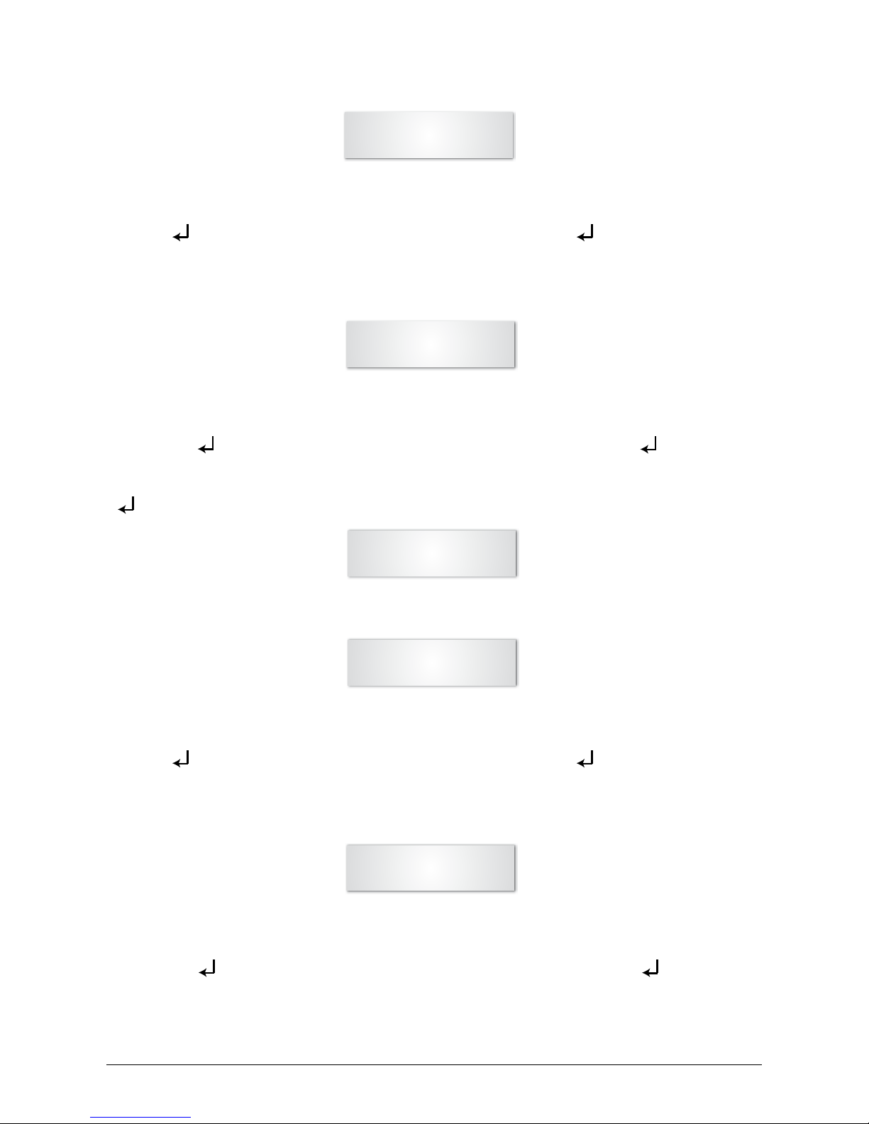
The rst line shows the limits according the standard. The second line shows the actual measured
trip limit and the test status if positive (pass). (If the test is negative (failed), press „ESC“ and the
display goes back to the main menu and the inverter is in error condition.).
Pressing the test is con rmed and the autotest routine continue. If is not pressed, the result
is shown for 10 seconds. After this time, the result is con rmed automatically.
Page 24
22 Operation and installation manual SOLIVIA 2.5 EU G3
The rst line shows the actual high frequency limit and detection time settings according to the
standards. Since the protection is not sensitive to the frequency variations less than 40 ms (two
line cycles of the grid voltage at nominal frequency of 50 Hz), the detection time has been set to 60
ms. Pressing the test starts. Test starts also automatically after 10 seconds if is not pressed.
The rst line shows the actual low frequency limit and detection time settings according to the
standards. Since the protection is not sensitive to the frequency variations less than 40 ms (two
line cycles of the grid voltage at nominal frequency of 50 Hz), the detection time has been set to 60
ms. Pressing the test starts. Test starts also automatically after 10 seconds if is not pressed.
If has been pressed the display shows, for example:
The limit „L:” will increase till crossing the actual measured grid voltage „A:”. Reached this condition
the inverter display shows, for example:
L: 230 V 0.164 S
A: 230 V UV pass
If the test is con rmed, the inverter performs the HFT test, high frequency test, which verify the high
frequency protection. The display shows:
L: 50.30 Hz < 0.06 S
Start HFT test?
L: 50.30 Hz HFT
A: 49.99 Hz RUN
The limit „L:” will decrease till crossing the actual measured grid frequency „A:”. Reached this condition the inverter display shows, for example:
L: 49.99 Hz 0.044 S
A: 49.99 Hz HF pass
If the test is con rmed, the inverter performs the LFT test, low frequency test, which verify the low
frequency protection. The display shows:
L: 49.70 Hz < 0.06 S
Start LFT test?
The rst line shows the limits according the standard. The second line shows the actual measured
trip limit and the test status if positive (pass). (If the test is negative (failed), press „ESC“ and the
display goes back to the main menu and the inverter is in error condition.).
Pressing the test is con rmed and the autotest routine continue. If is not pressed, the result
is shown for 10 seconds. After this time, the result is con rmed automatically.
Page 25
23
ENGLISH
Operation and installation manual SOLIVIA 2.5 EU G3
If has been pressed the display shows, for example:
L: 49.70 Hz LFT
A: 49.99 Hz RUN
The limit „L:” will increase till crossing the actual measured grid frequency „A:”. Reached this condition the inverter disconnects from grid and the display shows, for example:
L: 49.99 Hz 0.044 S
A: 49.99 Hz LF pass
If the test is con rmed, the autotest routine is nished. The display shows, for example:
Autotest Passed
Esc to continue
First line shows the actual autotest status. If all the single test are passed and con rmed, the actual
autotest status will be passed. Pressing „ESC” the display goes back to the main menu or the inverter returns automatically to normal operation after 10 seconds.
If the actual autotest status is failed, press „ESC” and the display goes back to the main menu and
the inverter is in error condition. The display shows “ AUTOTEST FAILED”. If the actual status is
failed it is possible to restart the autotest routine. If the autotest permanently fails please contact
the customer service.
If during the autotest is performed any grid or inverter error occurs, the autotest routine is aborted
and the display shows the actual failed autotest status directly after new calibration.
The inverter resets and performs a restart if the previous status was passed.
The autotest can be started only if the inverter is in normal operating conditions. It is not possible
to entry the autotest routine if the grid is not in the de ned tolerances, if any internal inverter error
occurs or the solar plant do not respect the speci cations.
A restart of the inverter will be done after the autotest, when the result of the current autotest is
different from the result from the autotest before.
While the autotest routine is ongoing, green LED is ashing, the red LED shows isolation measurement status and the yellow LED shows the status of last autotest (yellow LED on: last autotest was
failed; yellow LED off: last autotest was ok).
The rst line shows the limits according the standard. The second line shows the actual measured
trip limit and the test status if positive (pass). (If the test is negative (failed), press „ESC“ and the
display goes back to the main menu and the inverter is in error condition.).
Pressing the test is con rmed and the autotest routine continue. If is not pressed, the result
is shown for 10 seconds. After this time, the result is con rmed automatically.
Page 26
24 Operation and installation manual SOLIVIA 2.5 EU G3
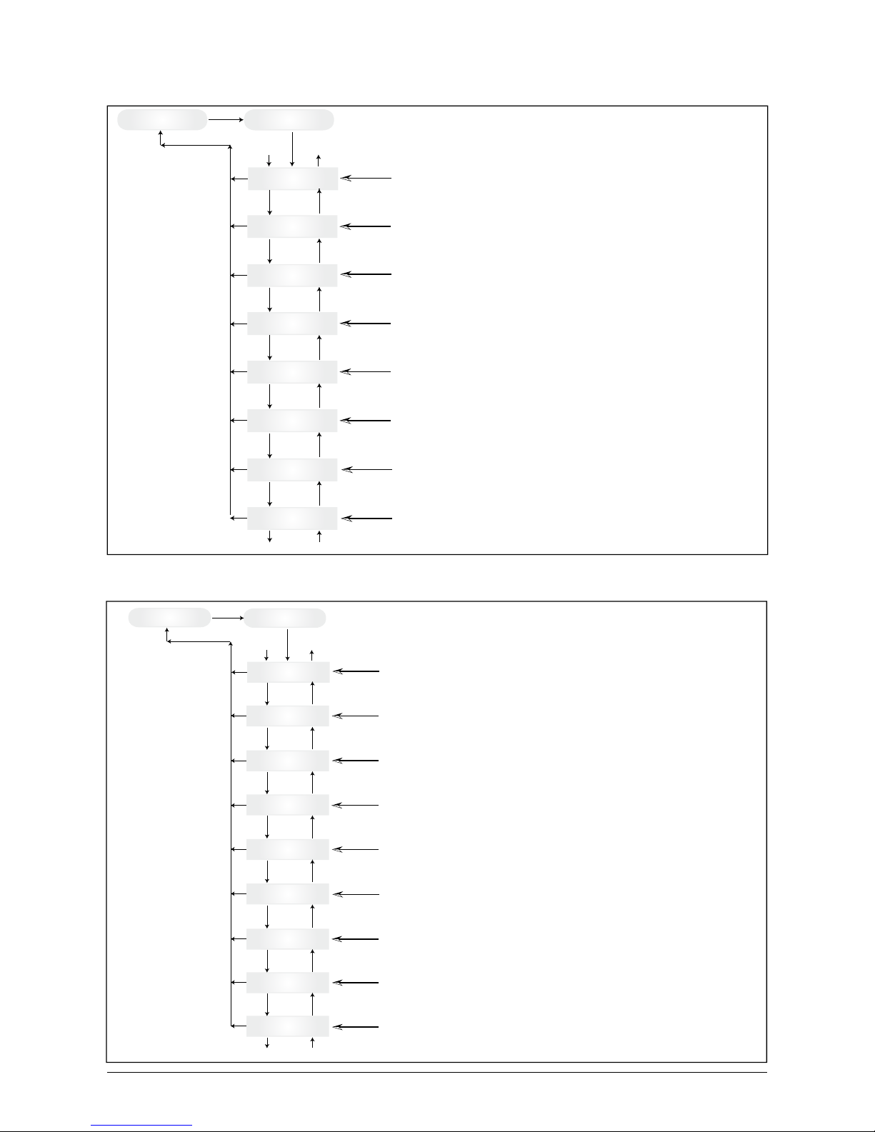
7.3.2 Submenu N (Now)
This menu item displays the active values.
Menu-N
Now (act. Data)
N->AC-Power
Value W
N->AC-Voltage
Value V
N->AC-Current
Value A
N->AC-Frequency
Value Hz
N->PV-Voltage
Value V
N->PV-Current
Value A
N->Time
HH:MM:SS
N->Date
WD, DD.MM.YYYY
Down
Down
Down
Down
Down
Down
Down
Up
Up
Up
Up
Up
Up
Up
Down to 2
1
Up to 1
2
Submenu N - Now
ESC
ESC
ESC
ESC
ESC
ESC
ESC
ESC
ENTER
Display of the
active output power
Display of the active
output voltage
Display of the active
output current
Display of the active
mains frequency
Display of the active
PV cell voltage
Display of the active
PV cell current
Display of the
current time
Display of current day
of the week and date
7.3.3 Submenu D (Day)
This menu item displays the daily values for the grid feed.
D->Energy
Value Wh
D->Revenue
Value Euro / GBP
D->AC-Pow.-Max
Value W
D->AC-Volt.-Max
Value V
D->AC-Volt.-Min
Value V
D->AC-Curr.-Max
Value A
D->AC-Freq.-Max
Value Hz
D->Runtime
Value min
Down
Down
Down
Down
Down
Down
Down
Up
Up
Up
Up
Up
Up
Up
Down to 2
1
Up to 1
2
Submenu D - Day
ESC
ESC
ESC
ESC
ESC
ESC
ESC
ESC
ENTER
D->AC-Freq.-Min
Value Hz
ESC
Down
Up
Menu-D
Day Statistic
Display of the daily
energy gain
Display of the daily revenue
Display of the daily
maximum output power
Display of the daily max.
output voltage
Display of the daily min.
output voltage
Display of the daily
maximum output current
Display of the daily
maximum output frequency
Display of the daily
minimum output frequency
Display of the daily operating
time of the solar inverter
Page 27
25
ENGLISH
Operation and installation manual SOLIVIA 2.5 EU G3
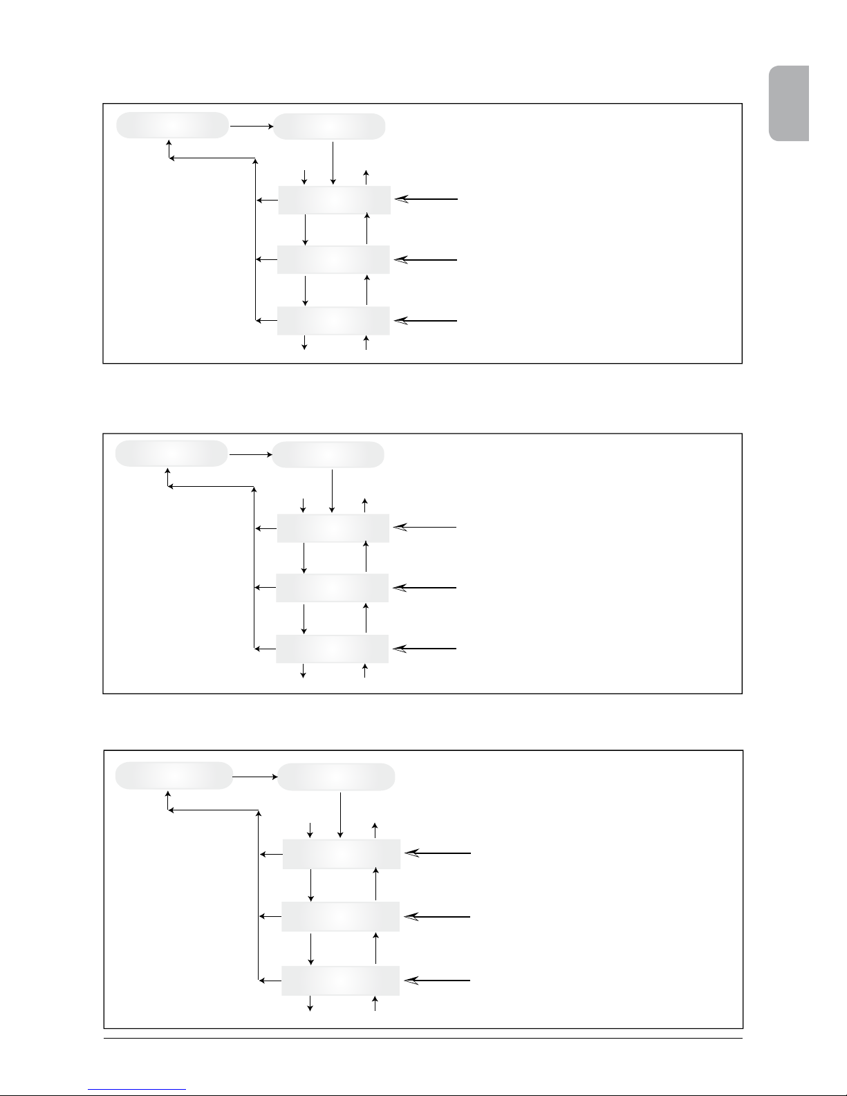
7.3.4 Submenu W (Week)
This menu item displays the average values of the current week.
W->Energy
Value kWh
W->Revenue
Value Euro / GBP
W->Runtime
Value h
Down
Down
Up
Up
Down to 2
1
Up to 1
2
Submenu W - Week
ESC
ESC
ESC
ENTER
Menu-W
Week Statistic
Display of the weekly
energy gain
Display of the weekly revenue
Display of the weekly operating
time of the solar inverter
7.3.5 Submenu M (Month)
This menu item displays the average values of the current month.
M->Energy
Value kWh
M->Revenue
Value Euro / GBP
M->Runtime
Value h
Down
Down
Up
Up
Down to 2
1
Up to 1
2
Submenu M - Month
ESC
ESC
ESC
ENTER
Menu-M
Month Statistic
Display of the monthly
energy gain
Display of the monthly revenue
Display of the monthly operating
time of the solar inverter
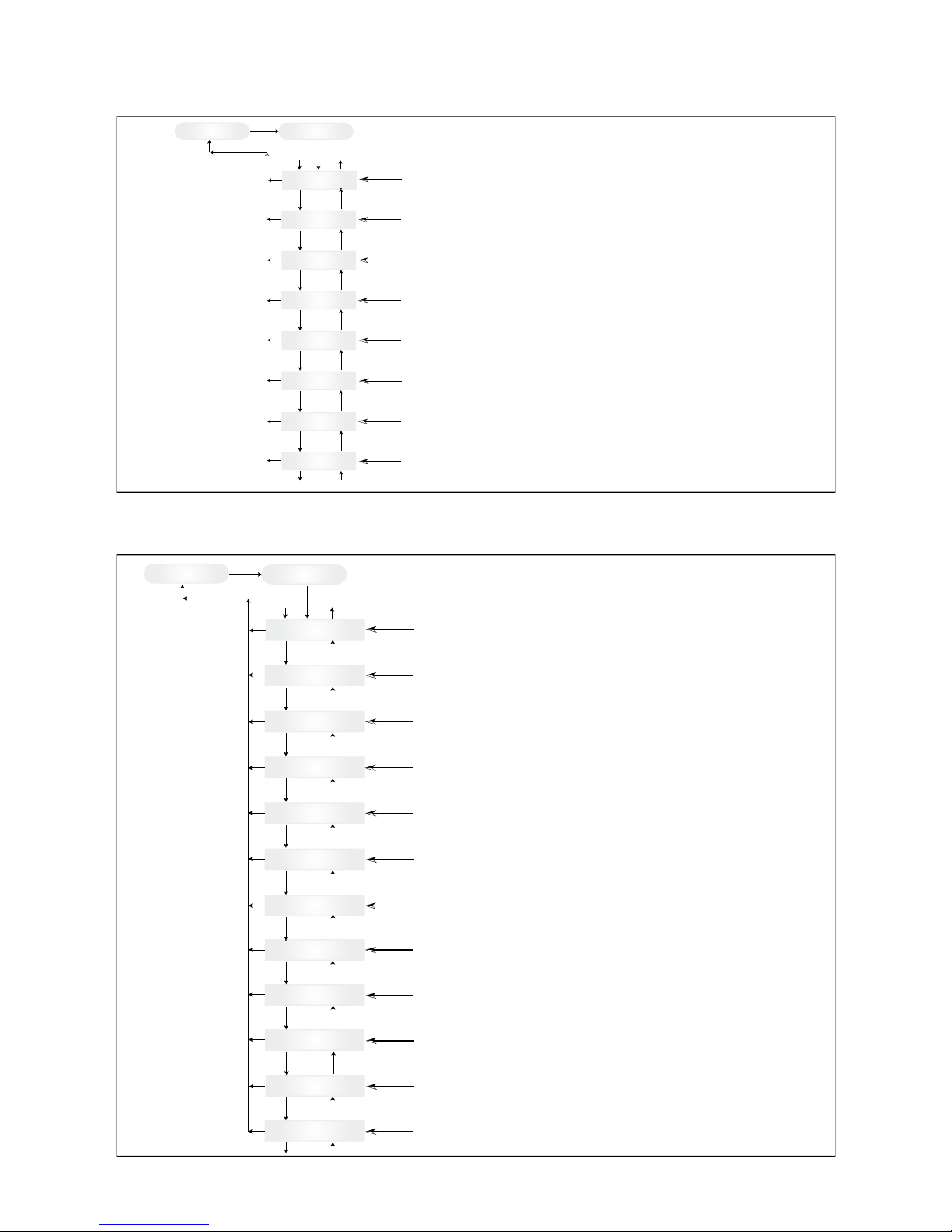
7.3.6 Submenu Y (Year)
This menu item displays the average values of the current year.
Y->Energy
Value kWh
Y->Revenue
Value Euro / GBP
Y->Runtime
Value h
Down
Down
Up
Up
Down to 2
1
Up to 1
2
Submenu Y - Year
ESC
ESC
ESC
ENTER
Menu-Y
Year Statistic
Display of the annual
energy gain
Display of the annual revenue
Display of the annual operating
time of the solar inverter
Page 28
26 Operation and installation manual SOLIVIA 2.5 EU G3
7.3.7 Submenu T (Total)
This menu item shows cumulated and maximum/minimum values since rst use.
T->Energy
Value kWh
T->Revenue
Value Euro / GBP
T->PV-Vol.-Max
Value V
T->PV-Cur.-Max
Value A
T->PV-Pow.-Max
Value W
T->Isolation-Max
Value kOhm
T->Isolation-Min
Value kOhm
T->Runtime
Value h
Down
Down
Down
Down
Down
Down
Down
Up
Up
Up
Up
Up
Up
Down to 2
1
Up to 1
2
Submenu T - Total
ESC
ESC
ESC
ESC
ESC
ESC
ESC
ESC
ENTER
Up
Menu-T
Total Statistic
Display of the total
energy gain
Display of the total
revenue
Display of the max.
PV cell voltage
Display of the max.
PV cell current
Display of the max.
PV cell power
Display of the largest
insulation resistance
Display of the smallest
insulation resistance
Display of the total operating
time of the solar inverter
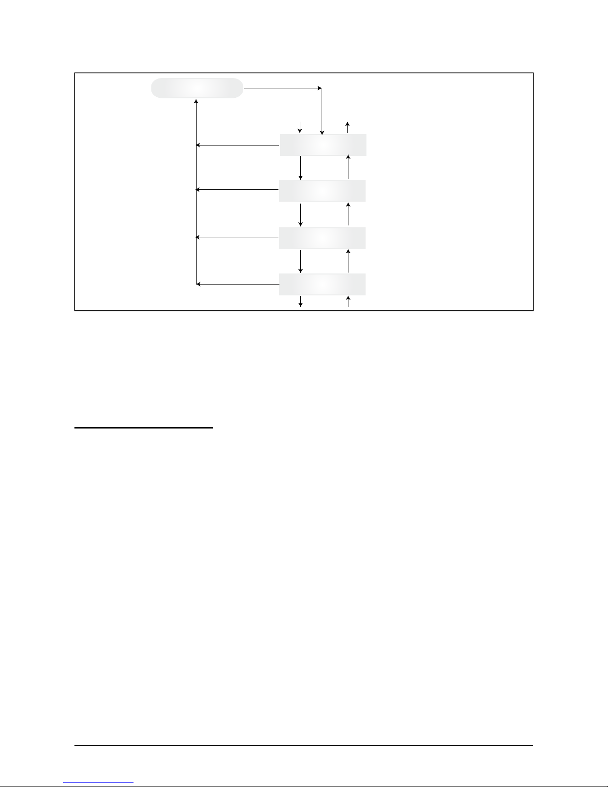
7.3.8 Submenu S (Setup)
This menu item is used for changing the presettings of the solar inverter.
S->LCD-Contrast
0 ... 9
S->Menu-Mode
Menu-Now ... Setup Inverter
S->LCD-Language
S->Cash per kWh
Value Euro / GBP
S->ID-Number
1 ... 254
S->PV ISO/GND
S->Baudrate
Value Baud
Down
Down
Down
Down
Down
Down
Down
Up
Up
Up
Up
Up
Up
Down to 2
1
Up to 1
2
Submenu S - Setup
ESC
ESC
ESC
ESC
ESC
ESC
ESC
ESC
ENTER
Up
S->Time
HH:MM:SS
Down
ESC
Up
S->Date
WD, DD.MM.YYYY
Down
ESC
Up
S->Firmware
Down
ESC
Up
S->Country Set
Name of country
Down
Up
ESC
Menu-s
Setup Inverter
S->LCD-Backlight
Auto / On
Adjustment of the LCD language
Adjustment of the firmware
Adjustment of the brightness of
the LCD display between 0 ... 9
Adjustment of the LCD
background lighting
Selection of the start menu
on restart of the device
Entry of feed-in remuneration in Euro/ kWh or GBP / kWh
Input of the ID number of the solar inverter
Adjustment of the baud rate
between 2400 ... 38400 Baud
Adjustment of the internal clock
Adjustment of current day of the week and date
ISO / GND Setup Menu
Adjustment of the country parameters
Page 29
27
ENGLISH
Operation and installation manual SOLIVIA 2.5 EU G3
7.3.8.1 Submenu S: Solar ISO / GND
More detailed information on the Solar ISO / GND menu within the submenu S (Setup).
Submenu Setup
PV ISO/GND
S->PV ISO/GND
ISO-ON-Warning
S->PV ISO/GND
ISO-ON-Error
S->PV ISO/GND
ISO/GND OFF
S->PV ISO/GND
PV+ grounded
S->PV ISO/GND
PV- grounded
Down
Down
Down
Down
Up
Up
Up
Up
Down to 5
6
Up to 6
5
ESC
ESC
ESC
ESC
ESC
ENTER
Use old setting
ENTER
ENTER
ENTER
ENTER
ENTER
Use new value
7.3.8.2 Submenu S: Country settings
More detailed information on the country settings menu within the submenu S (Setup).
Submenu Setup
Country settings
Name of country
Crit Undervolt
Value V < Value s
Low frequency
Value Hz < Value s
High frequency
Value Hz < Value s
Islanding
Active / Not active
Down
Down
Down
Down
Down
Down
Down
Up
Up
Up
Up
Up
Up
Up
Down to 5
6
Up to 6
5
ESC
ESC
ESC
ESC
ENTER
DC injection
Value mA < Value s
ESC
Undervolt
Value V < Value s
ESC
Overvolt
Value V < Value min
ESC
Crit Overvolt
Value V < Value s
ESC
Up
Power limitation
Value W
ESC
Sync Time
Value s
ESC
Down
Up
Down
Page 30
28 Operation and installation manual SOLIVIA 2.5 EU G3
7.3.8.3 Submenu S: Firmware
More detailed information on the rmware menu within the submenu S (Setup).
Submenu Setup
Firmware
S->Firmware
AC-Ctrl maj.min.bug
Down
Down
Down
Up
Up
Up
Down to 4
3
Up to 3
4
ESC
ESC
ESC
ESC
ENTER
S->Firmware
DC-Ctrl maj.min.bug
S->Firmware
SC-Ctrl maj.min.bug
S->Firmware
Display-Ctrl maj.min.bug
8 Diagnostics and data evaluation
8.1 Malfunction recti cation
The solar inverter is provided with an automatic diagnostics system which independently identi es
certain faults and which can make them visible on the display.
Troubleshooting in the eld
In principle, it is always worth attempting a reset by reinitializing the solar inverter whenever an error
message appears on the display.
To reset the device, proceed as follows:
1. Isolate the solar inverter from the grid (open automatic circuit breaker).
2. Switch off the DC disconnector.
3. Wait: approx. 1 minute.
4. Switch DC disconnector back on.
5. Switch in grid (close automatic circuit breaker).
(In the eld, the rst step is to scan for potential fault causes that could be picked up by the solar
inverter and result in tripping.)
Various key parameters can be scanned via the display, thereby enabling conclusions to be drawn
about potential fault causes.
Current values in the N menu
AC Voltage -> Display of current output voltage -> Voltage limiting values
AC Frequency -> Display of current grid frequency -> Frequency limiting values
Solar Voltage -> Display of current PV cell voltage -> Switch-in threshold
Page 31

29
ENGLISH
Operation and installation manual SOLIVIA 2.5 EU G3
8.2 Display messages
LED STATUS
DISPLAY
MESSAGE
CAUSE ELIMINATION
green: <on>
red: <on>
yellow: <on>
-
Display communication
faulty.
- If the fault persists after the device has
been reset, please inform your service
technician.
green: <off>
red: <off>
yellow: <on>
AC frequency
failure
Grid frequency overshooting or undershooting
specied limit range.
- Check the grid frequency via the display
in the N menu.
green: <off>
red: <off>
yellow: <on>
AC voltage
failure
Grid voltage overshooting
or undershooting specied
limit range.
- Check the grid voltage via the display in
the N menu.
- If no voltage present, check grid auto matic circuit breaker.
green: <off>
red: <off>
yellow: <on>
Autotest failed
(only for Italy)
The autotest status is in
error.
Repeat the autotest routine.
green: <ashes>
red: <off>
yellow: <off>
Calibration
ongoing
Check internal settings. Normal function before input mode.
green: <off>
red: <off>
yellow: <on>
DC injection
failure
DC component of inputside alternating current is
too high.
- If the fault persists after the device has
been reset, please inform your service
technician.
green: <off>
red: <off>
yellow: <on>
Error # 301
Internal communication
error or hardware fault.
- If the fault persists after the device has
been reset, please inform your service
technician.
green: <off>
red: <off>
yellow: <on>
Error # 302
The device trips and
reverts to grid input mode
once the temperature has
dropped.
- Check the installation site (no direct
sunlight, air circulation).
green: <off>
red: <on>
yellow: <off>
Error # 506
Error # 508
Isolation resistance fault
on the DC side during
start-up phase (# 508) or
running phase (# 506).
- Check the isolation resistance on the DC
side of the PV modules.
green: <on>
red: <on>
yellow: <off>
Isolation startup warning
Isolation running warning
Isolation resistance fault
on the DC side during
start-up phase or running
phase.
- You must check the isolation resistance
on the DC side of the PV modules.
Solar inverter is still feeding!
green: <on>
red: <on>
yellow: <off>
PV+ grounding fault
PV- grounding
fault
Connection PV+ (PV-)
to GND is interrupted or
wrong pole is connected
to GND.
- Check that the GND connection has been
made correctly and/or check the fuse in
the grounding path. Change the fuse if
necessary. The solar inverter remains in
feed-in operation.
green: <off>
red: <off>
yellow: <on>
Relay error
One of the anti-islanding
protection output relays is
faulty / defective.
- The solar inverter is defective.
- Return the device.
green: <off>
red: <off>
yellow: <on>
Revision error
Versions of hard- and software are not compatible.
- If the fault persists after the device has
been reset, please inform your service
technician.
Page 32

30 Operation and installation manual SOLIVIA 2.5 EU G3
Please follow the instructions above before contacting your service technician!
LED STATUS
DISPLAY
MESSAGE
CAUSE ELIMINATION
green: <on>
red: <on>
yellow: <on>
Self test
ongoing
Initialization of solar inverter on start-up.
The rst time the solar inverter is started
up:
- Normal function with a PV cell voltage
of between 100 V and 150 V.
green: <ashes>
red: <off>
yellow: <off>
PV power too
low
Insufcient input power.
- Insufcient insolation (dawn/twilight).
- Check the PV cell voltage via the
display in the N menu.
green: <ashes>
red: <off>
yellow: <off>
PV voltage too
low
PV generator voltage between 100 V and 150 V.
- Insufcient insolation.
- Check the PV cell voltage via the
display in the N menu.
green: <ashes>
red: <off>
yellow: <off>
Synchronize
to AC
Check grid voltage and
grid frequency for grid
input mode.
- Normal function before input mode.
green: <on>
red: <off>
yellow: <ashes>
Varistor
warning
Internal varistor at the DC
input is defective.
- Although you can, in theory, carry on
using the solar inverter, the varistors
should be replaced at the earliest oppor
tunity. This will involve returning the
device.
Page 33

31
ENGLISH
Operation and installation manual SOLIVIA 2.5 EU G3
9 Technical data
* The maximum AC power value indicates the power
an inverter might be able to deliver. However, such a
maximum AC power may not necessarily be achieved.
** AC voltage and frequency range will be programmed
according to the individual country requirements.
INPUT (DC)
Max. recommended PV
power
3100 W
P
Nominal power 2750 W
Voltage range 125 ... 540 V
MPP range 150 ... 450 V
Full power MPP range 150 ... 450 V
Nominal current 10.0 A
Max. current 18.0 A
Stand-by power < 0.2 W
OUTPUT (AC)
Max. power * 2600 W
Nominal power
2500 W
Voltage range ** 184 ... 264 V
Nominal current 11.0 A
Max. current 13.0 A
Nominal frequency 50 Hz
Frequency range ** 47.0 ... 52.0 Hz
Power factor > 0.99 @ nominal power
Total harmonic
distortion (THD)
< 3 % @ nominal power
GENERAL SPECIFICATION
Model name SOLIVIA 2.5 EU G3
Max. efficiency 96.0 %
Efficiency EU 94.4 %
Operating temperature -25 ... +70 °C
Storage temperature -25 ... +80 °C
Humidity 0 ... 98 %
MECHANICAL DESIGN
Size (L x W x D) 410 x 410 x 180 mm
Weight 21.5 kg
Cooling Convection
AC connector Wieland RST25i3S
DC connector pairs 3 Tyco Solarlok
Communication
interfaces
2 Harting RJ45 / RS485
DC disconnector Integrated
Display LCD; 3 LEDs
STANDARDS / DIRECTIVES
Protection degree IP65
Safety class 1
Configurable trip
parameters
Yes
Insulation monitoring Yes
Overload behavior
Current limitation;
power limitation
Safety
EN60950-1; EN50178;
IEC62103; IEC62109-1 / -2
Anti-islanding
protection
DIN VDE 0126-1-1; RD 1663;
RD 661; ENEL G.L. 2010; UTE
15712-1; Synergrid C10/11;
EN 50438; G83/1-1
EMC
EN61000-6-2; EN61000-6-3;
EN61000-3-2; EN61000-3-3
Page 34

32 Operation and installation manual SOLIVIA 2.5 EU G3
10 Appendix
10.1 Connection examples
House connection box
House connection line
Low-voltage network ~ 400 / 230 V
VNB
Customer
Owner boundary
Z
(1)
Z
(2)
Measurement unit
(1) Meter for power consumption
(2) Meter for power feed-in
with back stop in each case
Remark: A meter can also be employed
which registers both energy directions separately
=
~
~ 400 / 230 V
Consumer
equipment of
the customer
Photovoltaic
generator with
power inverter
max. 4.6 kVA
Switching equipment
Electric circuit distributor
Anti-islanding protection with voltage and
frequency monitoring, as well as network
impedance measurement
Short-circuit protection
Overload protection
Individual in-plant generation system in parallel operation without isolated
operation possibility, single-phase feed with anti-islanding protection.
House connection box
House connection line
Low-voltage network ~ 400 / 230 V
VNB
Customer
Owner boundary
Z
(1)
Z
(2)
Measurement unit
(1) Meter for power consumption
(2) Meter for power feed-in
with back stop in each case
Remark: A meter can also be
employed which registers both energy
directions separately.
(3) Meter for power take-off of the
customer system
=
~
~ 400 / 230 V
Consumer equipment
of the customer
Photovoltaic
generator with
power inverter
max. 4.6 kVA
Switching equipment
Electric circuit distributor
Anti-islanding protection with voltage and
frequency monitoring, as well as network
impedance measurement
Short-circuit protection
Overload protection
Individual in-plant generation system in parallel operation without isolated
operation possibility, single-phase feed with anti-islanding protection, separate feed.
Z
(3)
Page 35

33
ENGLISH
Operation and installation manual SOLIVIA 2.5 EU G3
10.2 Overview of connection diagrams
+
-
DC terminal strip
DC disconnector
-
~
Solivia 2.5
3 3
Z
Meter for
power feed-in
3
Z
3
3
3
Meter for
power
consumption
House
connection
box
Selective
main line
circuit breaker
House
connection
line
Consumer
equipment
Automatic
circuit breaker
type B 16 A
+
-
PV generator
PV generator
+
-
DC disconnector
-
~
Solivia 2.5
Automatic circuit
breaker
type B 16 A
PV generator
DC disconnector
-
~
Automatic
circuit breaker
type B 16 A
PV generator
kWh
kWh
Customer
Meter for
power feed-in
Meter for
power
consumption
Solivia 2.5
Page 36

34 Operation and installation manual SOLIVIA 2.5 EU G3
DC disconnector
-
~
1
2
3
PV generator
-
~
-
~
L1 N PE
L2 N PE
L3 N PE
Fuse
L1
N
n
...
PE
L2
L3
Solivia 2.5
Page 37

35
ENGLISH
Operation and installation manual SOLIVIA 2.5 EU G3
11 Glossary
AC
Abbreviation for „Alternating Current“.
Anti-islanding protection
This is a unit for grid monitoring with assigned switching elements (anti-islanding protection) and is
an automatic isolation point for small power generation systems (to 30 kWp).
BDEW
Union of German Electrical Power Stations.
CE
With the CE identication code, the manufacturer conrms the conformity of the product with the
valid EC Guideline and compliance with the signicant requirements stipulated therein.
DC
Abbreviation for „Direct Current“.
EMC
The Electro-Magnetic Compatibility (EMC) concerns the technical and legal basics of the mutual
inuencing of electrical devices through electromagnetic elds caused by them in electrical engineering.
Galvanical isolation
No conductive connection between two component parts.
Initialization
Under initialization (cf. English to initialize) is understood the part of the loading process of a program, in which the storage space required for the execution (e.g. variable, code, buffers ...) for the
program is reserved and is lled with initial values.
Local utility company
By local utility company is meant a company which generates electrical energy and distributes it
over the public grid.
MPP
The Maximum Power Point is the point of the current-voltage diagram of a PV cell at which the
largest power can be tapped off, i.e. the point at which the product of current and voltage has its
maximum value.
Nominal power
Nominal power is the maximum permissible continuous power output indicated by the manufacturer
for a device or a system. Usually the device is also optimized so that the efciency is at its maximum
in case of operation with nominal power.
Nominal current
Nominal current is the absorbed current in case of electrical devices if the device is supplied with
the nominal voltage and yields its nominal power.
PE
In electric systems and cables a protective earth conductor is frequently employed. This is also
called grounding wire, protective grounding device, soil, grounding or PE (English „protective
earth“).
Page 38

36 Operation and installation manual SOLIVIA 2.5 EU G3
Photovoltaics (abbr.: PV)
The conversion of PV energy into electrical energy.
The name is composed of the component parts: Photos - the Greek word for light - and Volta - after
Alessandro Volta, a pioneer in electrical research.
Power dissipation
Power dissipation is designated as the difference between absorbed power and power of a device
or process yielded. Power dissipation is released mainly as heat.
PV cell
PV cells are large-surface photodiodes which convert light energy (generally sunlight) into electrical
energy. This comes about by utilization of the photoelectric effect (photovoltaics).
PV generator
System comprising a number of PV modules.
PV module
Part of a PV generator; converts PV energy into electrical energy.
RJ45
Abbreviation for standardized eight-pole electrical connector connection. RJ stands for Registered
Jack (standardized socket).
RS485 (EIA485)
Differential voltage interface on which the genuine signal is transmitted on one core and the negated (or negative) signal on the other core.
Separate grid system
Energy supply equipment which is completely independent of an interconnected grid.
Solar inverter
is an electrical device which converts DC direct voltage into AC voltage and/or direct current into
alternating current.
String
Designates a group of electrical PV modules switched in series.
String solar inverter (solar inverter concept)
The PV generator is divided up into individual strings which feed into the grid over their own string
solar inverters in each case. In this way, the installation is considerably facilitated and the gain decrease, which can arise from the installation or from different shading conditions of the PV modules,
is considerably reduced.
TAB (2000)
The TAB 2000 are the technical regulations governing connection to the low-voltage grid operated
by distribution system operators in Germany. These Technischen Anschlussbestimmungen or TAB
for short have been in force since the year 2000. They dene the requirements imposed by DSOs
on the electrical systems operated by the end customers of utility companies.
VDE
Verband der Elektrotechnik, Elektronik und Informationstechnik e. V.
(Association of Electrical Engineering, Electronics and Information Technology).
Page 39

37
ENGLISH
Operation and installation manual SOLIVIA 2.5 EU G3
12 Guarantee
Register now on our homepage at https://guarantee.solar-inverter.com and you will receive a free
extension of the guarantee on your SOLIVIA string inverter from 5 to 10 years. The registration
and the original sales receipt are required for this extension of the guarantee.
If you have not registered, you will continue to receive the 5-year standard guarantee.
Page 40

Bedienungsanleitung SOLIVIA 2.5 EU G338
Page 41

39
DEUTSCH
Bedienungsanleitung SOLIVIA 2.5 EU G3
Dieser Bedienungsanleitung sind Änderungen vorbehalten.
Bitte informieren Sie sich auf unserer Website www.solar-inverter.com
bezüglich der aktuellsten Version der Bedienungsanleitung.
© Copyright – Delta Energy Systems (Germany) GmbH – Alle Rechte vorbehalten.
Diese Anleitung liegt unseren Produkten bei und ist für den Gebrauch durch den Endanwender bestimmt. Die in dieser Anleitung
enthaltenen technischen Anweisungen und Illustrationen sind vertraulich zu behandeln und dürfen ohne die vorherige schriftliche
Genehmigung durch die Service-Ingenieure von Delta Energy Systems weder ganz noch auszugsweise vervielfältigt werden. Der
Endanwender darf die hierin enthaltenen Informationen nicht an Dritte weitergeben oder diese Anleitung für andere Zwecke als die
Gewährleistung einer ordnungsgemäßen Anwendung der Produkte verwenden.
Alle Informationen und Spezikationen unterliegen Änderungen ohne vorherige Ankündigung.
Page 42

40 Bedienungsanleitung SOLIVIA 2.5 EU G3
Page 43

41
DEUTSCH
Bedienungsanleitung SOLIVIA 2.5 EU G3
Inhaltsangabe
1 Lieferumfang 42
2 Allgemein / Sicherheitshinweise 42
3 Einleitung 43
4 System 43
4.1 Datenauswertung und Kommunikation 43
4.2 Technischer Aufbau des Solar Inverters 44
4.3 Geräteübersicht 45
5 Installation 46
6 Gerätemontage 46
6.1 Installationsort 46
6.2 Mindestanforderungen 46
6.3 Wartung 47
6.4 Montage 47
6.5 Umgebungstemperatur 48
6.6 Netzanschluss 48
6.7 Anschluss der PV Module 48
6.7.1 Ausgangsleistung über PV Spannung 50
6.7.2 Ausgangsleistung über AC Spannung 50
6.7.3 Wirkungsgrad 51
6.8 Schnittstellenanschluss RS485 (EIA485) 51
6.9 Elektrischer Anschluss und Inbetriebnahme 53
6.10 Einrichtung/Einstellungen 54
6.11 LED Betriebs- und Störungsanzeige 56
7 Bedienkonzept 57
7.1 Das Display 57
7.2 Navigation im Display 57
7.3 Hauptmenü 57
7.3.1 Autotest (nur für Italien) 59
7.3.2 Untermenü N (Now) 62
7.3.3 Untermenü D (Day) 62
7.3.4 Untermenü W (Week) 63
7.3.5 Untermenü M (Month) 63
7.3.6 Untermenü Y (Year) 63
7.3.7 Untermenü T (Total) 64
7.3.8 Untermenü S (Setup) 64
7.3.8.1 Untermenü S: Solar ISO/GND 65
7.3.8.2 Untermenü S: Ländereinstellungen 65
7.3.8.3 Untermenü S: Firmware 66
8 Diagnose und Datenauswertung 66
8.1 Störungsbehebung 66
8.2 Displaymeldungen 67
9 Technische Daten 69
10 Anhang 70
10.1 Anschlussbeispiele 70
10.2 Übersichtsschaltpläne 71
11 Glossar 73
12 Garantie 75
12 Zertifikate 381
Page 44

42 Bedienungsanleitung SOLIVIA 2.5 EU G3
1 Lieferumfang
• Solar Inverter SOLIVIA 2.5 EU G3
• Wandhalterung
• Bedienungsanleitung
• AC Netzstecker
2 Allgemein / Sicherheitshinweise
Herzlichen Glückwunsch zum Kauf dieses technisch hochwertigen Solar Inverter SOLIVIA 2.5 EU
G3.
Die vorliegende Anleitung hilft Ihnen, sich mit diesem Produkt vertraut zu machen.
Bitte beachten Sie die Sicherheitsbestimmungen der einzelnen Länder (z.B. für Deutschland: VDE,
BDEW, BGFE, technische Anschlussbedingungen für örtliches Versorgungsunternehmen). Eine
vorsichtige Handhabung Ihres Produkts wird zur Haltbarkeit und Zuverlässigkeit während seiner
Betriebsdauer beitragen. Dies sind wesentliche Voraussetzungen dafür, dass Sie den besten Nutzen aus Ihrem Produkt ziehen.
Bitte beachten Sie folgende Sicherheitshinweise:
• Während des Betriebes elektrischer Geräte stehen bestimmte Teile unter gefährlicher Spannung.
• Unsachgemäßer Umgang kann zu Körperverletzung und Sachschäden führen!
• Halten Sie die Installationsvorschriften ein.
• Installations- und Inbetriebnahmearbeiten dürfen nur durch Elektrofachkräfte ausgeführt werden.
• Reparaturarbeiten am Gerät dürfen nur vom Hersteller durchgeführt werden.
• Bitte beachten sie alle Punkte in der Bedienungsanleitung!
• Trennen Sie das Gerät vom Netz und von den PV Modulen, bevor Sie Arbeiten daran durchführen.
• Bei hoher Leistung und hoher Umgebungstemperatur kann die Gehäuseoberäche heiß werden.
• Ausreichende Kühlung des Gerätes ist notwendig.
• Aufgrund des hohen Gewichts von > 18 kg sollte der Solar Inverter nur mit mindestens 2 Personen
gehoben werden.
• Beachten Sie, dass das Gerät einen erhöhten Ableitstrom besitzt. Ein Betrieb mit angeschlos senem PE Leiter ist zwingend erforderlich.
Bitte beachten Sie, dass das Gerät unter keinen Umständen geöffnet werden darf, da sonst die Garantie erlischt!
Nachdem Sie das Gerät vom Netz und von den PV Modulen getrennt
haben, sind innerhalb des Gerätes für mindestens 5 Minuten gefährliche
Spannungen vorhanden!
Page 45

43
DEUTSCH
Bedienungsanleitung SOLIVIA 2.5 EU G3
3 Einleitung
Mit diesem Gerät haben Sie einen Solarwechselrichter für den Anschluss von photovoltaischen
Systemen an das Versorgungsnetz erworben. Dieser europäische Solarwechselrichter kann in folgenden Ländern, für die er auch zugelassen ist, benutzt werden: Belgien, Deutschland, Frankreich,
Griechenland, Italien, Portugal, Spanien,Tschechische Republik und Vereinigtes Königreich. Der
Solarwechselrichter zeichnet sich durch sein fortschrittliches Gehäusedesign sowie modernste Hochfrequenztechnologie aus, die den höchsten Grad an Efzienz ermöglichen.
Der Solarwechselrichter umfasst Überwachungsaggregate, wie etwa den Schutz gegen Inselbildung. Die Funktion des Schutzes gegen Inselbildung (automatischer Isolierungspunkt für betriebsinterne Generierungssysteme) schreibt die Einhaltung der Spezikationen von DIN VDE 0126-1-1,
EN 50438, ENEL G.L., RD 1663, RD 661, UTE 15712-1, Synergrid C10/11 und G83/1-1 vor, wie
auch die Einhaltung der Richtlinien für den Parallelbetrieb von Stromerzeugungssystemen auf dem
Niederspannungsnetz Ihrer örtlichen Versorgungsunternehmen. Diese werden durch Zertikate bescheinigt (siehe § 13).
Der Wechselrichter kann innerhalb oder außerhalb von Gebäuden benutzt werden (IP65).
In der folgenden technischen Beschreibung werden dem Installateur wie auch dem Benutzer die
genauen Funktionen erläutert, die für die Installation, Inbetriebnahme und Handhabung des Solar
Inverters erforderlich sind.
4 System
Der Solar Inverter wandelt den von den Solarzellen gewonnenen Gleichstrom in Wechselstrom
um. Dies ermöglicht es Ihnen, Ihre selbstproduzierte Solarenergie in das öffentliche Stromnetz
einzuspeisen.
Dank eines efzienten MPP-Trackings ist selbst bei trübem und bewölktem Himmel eine maximale
Leistung der Solaranlage gesichert.
Durch das Stringkonzept wird immer eine Reihenschaltung von Solarmodulen (String) bzw. eine
Parallelschaltung von Strings mit gleicher Spannung an den Solar Inverter angeschlossen, sodass
der Verkabelungsaufwand der Photovoltaikanlage wesentlich reduziert wird. Durch das Verschalten
in Strings kann außerdem die Photovoltaikanlage optimal auf den Eingangsspannungsbereich des
Solar Inverters angepasst werden.
4.1 Datenauswertung und Kommunikation
Die integrierte Datenanzeige, -aufbereitung und -kommunikation des Gerätes ermöglicht eine einfache Bedienung des Solar Inverters. Überwachung des Betriebszustandes und Meldung von Betriebsstörungen sind über das Display des Geräts abrufbar. Die Datenschnittstellen ermöglichen
das Downloaden der Daten, die mit Hilfe eines PC-Systems ausgewertet werden können und somit
eine kontinuierliche Erfassung der Betriebsdaten gewährleisten.
Diese Funktionalität ist optimal durch das angebotene Zubehör (z.B. WEB`log von Meteocontrol)
erreichbar und eine vollständige und lückenlose Überwachung des Solar Inverters wird gewährleistet.
Das Auslesen der Daten über die integrierte Schnittstelle und das Display ist nur im Solarbetrieb
möglich.
Page 46

44 Bedienungsanleitung SOLIVIA 2.5 EU G3
4.2 Technischer Aufbau des Solar Inverters
Eine Potentialtrennung des Solar Inverters vom Netz wird durch einen Hochfrequenz-Umrichter mit
integriertem Transformator erreicht. Dabei wird die Photovoltaikspannung so eingestellt, dass die
maximale Abgabeleistung der Solarmodule auch bei unterschiedlichen Einstrahlungsstärken und
Temperaturen erreicht wird (MPP-Tracking).
Der MPP Bereich des Solar Inverters beträgt 150 V bis 450 V. Dies ermöglicht die Verwendung von
Solarmodulen verschiedener Hersteller. In jedem Fall ist zu berücksichtigen ist, dass die maximale
Leerlaufspannung von 540 V auf keinen Fall überschritten wird. Bitte beachten Sie, dass die maximale Leerlaufspannung bei den tiefsten zu erwartenden Temperaturen auftritt. Nähere Angaben
zur Temperaturabhängigkeit nden Sie im Datenblatt der Solarmodule. Der Eigenverbrauch des
Gerätes ist auf ein Minimum begrenzt.
Das hochwertige Aluminiumgehäuse entspricht der Schutzart IP65 (strahlwassergeschützt und
staubdicht) und ist durch eine Ober ächenveredelung vor Witterungsein üssen geschützt. Das
Kühlpro l ist so konzipiert, dass ein Betrieb des Solar Inverters bei Umgebungstemperaturen von
-25°C bis +70°C möglich ist.
Zur Abfuhr der durch die Spannungsumwandlung verursachten Wärme dient ein Kühlpro l. Eine
interne Temperaturregelung schützt das Gerät vor zu hohen Temperaturen im Inneren. Bei hohen
Umgebungstemperaturen wird die maximal übertragbare Leistung begrenzt.
Der Solar Inverter wird durch Mikrocontroller gesteuert, welche auch die Kommunikation der
Schnittstellen und die Anzeigen von Messwerten und Meldungen im Display realisieren.
Zwei unabhängige und redundante Mikrocontroller steuern die Überwachung des Versorgungsnetzes, was den Einspeiserichtlinien Ihres örtlichen Versorgungsunternehmens und DIN VDE
0126-1-1, EN 50438, ENEL G.L., RD 1663, RD 661, UTE 15712-1, Synergrid C10/11 und G83/1-1
(Schutz gegen Inselbildung) entspricht. Dies ermöglicht eine Installation des Solar Inverters in das
betriebsinterne Stromnetz.
Der Schutz von Personen wird durch die galvanische Trennung von Netz und Solarmodul erfüllt.
Die galvanische Trennung zwischen Netz und Solarmodul entspricht einer Basisisolation. Zwischen
Netz, Solarmodulen und den berührbaren Schnittstellen (Display und RS485 Schnittstelle) ist eine
verstärkte Isolation für maximalen Personenschutz realisiert. Einschlägige Normen bezüglich der
elektromagnetischen Verträglichkeit (EMV) und der Sicherheit werden erfüllt.
Der Solar Inverter ist ausschließlich im Netzparallelbetrieb funktionsfähig. Eine selbsttätig wirkende
Freischaltstelle, welche von einer Zulassungsstelle abgenommen wurde, gewährleistet die sichere
Abschaltung bei Netztrennung oder Netzstörungen und vermeidet einen Inselbetrieb.
Es handelt sich dabei um eine sogenannte „Selbsttätige Freischaltung für Eigenerzeugungsanlagen einer Nennleistung ≤ 4,6 kVA mit einphasiger Paralleleinspeisung über Solar Inverter in das
Netz der öffentlichen Versorgung“.
Page 47

45
DEUTSCH
Bedienungsanleitung SOLIVIA 2.5 EU G3
4.3 Geräteübersicht
(1) Anschlüsse für PV Module
(2) DC Freischalter
(3) Netzanschluss
(4) Schnittstellenanschluss RS485 (EIA485)
(5) Display für Zustandsanzeige und Tastenfeld zur Bedienung
(6) Leuchtdioden zur Betriebszustandsanzeige
DEUTSCH
(1)
(2)
(3)
(5)
(6)
(4)
Page 48

46 Bedienungsanleitung SOLIVIA 2.5 EU G3
5 Installation
Die Installation des Solar Inverters darf ausschließlich von Elektrofachkräften vorgenommen werden!
Die empfohlenen Sicherheitsbestimmungen, die technischen Anschlussbedingungen (TAB 2000)
wie auch DIN VDE 0126-1-1, EN 50438, ENEL G.L., RD 1663, RD 661, UTE 15712-1, Synergrid
C10/11 und G83/1-1 Spezikationen sollten eingehalten werden.
Wichtig für Netz „DE LVD“: Gemäß der Anwendungsregel VDE-AR-N 4105 darf die installierte Leistung des Solargenerators 3,68 kW nicht überschreiten.
Zur Durchführung einer Strommessung muss zwischen dem Netzeinspeisungspunkt und dem Solar Inverter ein Messgerät angebracht werden (gemäß der Richtlinie Ihres örtlichen Versorgungsunternehmens bezüglich “Betriebsinterne Stromerzeugungssysteme auf dem Niederspannungsnetz”).
Aufgrund des integrierten Schutzes gegen Inselbildung wird die Funktion des empfohlenen Kuppelschalters gemäß der Richtlinie Ihres örtlichen Versorgungsunternehmens erfüllt.
Achtung: Der Kurzschlussstrom erhöht sich im Übergabepunkt zum öffentlichen Stromversorgungsnetz um den Nennstrom der angeschlossenen Solar Inverter.
6 Gerätemontage
6.1 Installationsort
• Das Gerät auf einem nicht brennbaren Untergrund installieren.
• Montage auf Resonanzkörpern (Leichtbauwände etc.) vermeiden.
• Eine Montage ist sowohl im Innen- als auch im geschützten Außenbereich möglich.
• Eine erhöhte Umgebungstemperatur kann den Ertrag der PV Anlage mindern.
• Leichte Geräuschentwicklung ist möglich (Installation im Wohnbereich vermeiden).
• Auf Lesbarkeit der LEDs und des Displays achten (Ablesewinkel / Montagehöhe).
• Das Gerät ist mit UV resistenten Komponenten ausgerüstet; direkte Sonneneinstrahlung sollte
dennoch vermieden werden.
• Trotz der Gehäuseschutzart IP65 und der Verschmutzungskategorie III muss darauf geachtet
werden, dass das Gerät nicht zu stark verschmutzt wird.
• Ein zu stark verschmutztes Gehäuse kann zu verminderten Erträgen führen.
6.2 Mindestanforderungen
• Die freie Konvektion um den Solar Inverter darf nicht beeinträchtigt sein.
• Zur Luftzirkulierung einen Freiraum von ca. 10 cm seitlich und ca. 50 cm oben und unten vom
Gerät belassen.
• Die Netzimpedanz am Einspeisepunkt ist zu beachten (Leitungslänge, -querschnitt).
• Die vorgeschriebene Einbaulage ist einzuhalten (senkrecht).
• Die unbenutzten DC Stecker (Tyco) und Schnittstellenstecker müssen durch Dichtungsstopfen
verschlossen werden.
Page 49

47
DEUTSCH
Bedienungsanleitung SOLIVIA 2.5 EU G3
319.5
150
320
200
6.5
12
Ø
12.5
90
38
12
410 ± 0.5
6.3 Wartung
Achten Sie während der gesamten Betriebsdauer darauf, dass der Solar Inverter nicht abgedeckt
wird. Außerdem muss in regelmäßigen Abständen das Gehäuse von Staub und Verschmutzungen
befreit werden. Im Gerät benden sich keine zu wartenden Komponenten und das Gehäuse darf
unter keinen Umständen geöffnet werden.
6.4 Montage
Zur problemlosen Montage des Solar Inverters sollten Sie die mitgelieferte Wandhalterung verwenden. Die Anbringung sollte mit Hilfe geeigneter Schrauben erfolgen. Montieren Sie die Wandhalterung so, dass der Solar Inverter später nur noch eingehängt werden muss. Danach ist das Gerät
fest zu schrauben.
Montageanleitung
1. Montieren Sie die Wandhalterung an mindestens vier der acht Löcher mit geeigneten
Schrauben (max. 6mm Ø). Zum Markieren der Positionen für die Bohrlöcher können Sie
die Wandhalterung als Bohrschablone verwenden.
2. Heben Sie den Solar Inverter aufgrund des Gewichts von 21,5 kg mit mindestens zwei
Personen aus dem Transportkarton.
3. Hängen Sie den Solar Inverter mit mindestens zwei Personen in die Wandhalterung ein.
4. Schrauben Sie die mitgelieferten Befestigungsmuttern und Unterlagscheiben auf den
Gewindebolzen zur Gerätesicherung fest.
5. Prüfen Sie den Solar Inverter auf festen Sitz.
Wandhalterung
Gewindebolzen
zur Gerätesicherung
Gewindebolzen
zur Gerätesicherung
Page 50

48 Bedienungsanleitung SOLIVIA 2.5 EU G3
6.5 Umgebungstemperatur
Der Solar Inverter kann bei einer Umgebungstemperatur von -25°C bis +70°C betrieben werden.
Das folgende Diagramm gibt die automatische Leistungsreduzierung der vom Solar Inverter abgegebenen Leistung in Abhängigkeit von der Umgebungstemperatur wieder.
Das Gerät sollte an einem gut belüfteten, kühlen und trockenen Montageort installiert werden.
6.6 Netzanschluss
Über einen AC Stecker Wieland RST25i3S wird das Netz (AC Output) angeschlossen. Auf dem
Schraubklemmen-Anschluss des Steckers nden Sie die richtige Belegung. Der Solar Inverter
muss über eine dreiadrige Leitung (L, N, PE) an das Netz angeschlossen werden. Die angeschlossene AC Leitung muss vor dem Lösen bzw. vor der Montage des AC Steckers spannungsfrei geschaltet werden.
Der Anschluss an den AC Stecker Wieland muss mit einer exiblen Leitung und Leiterquerschnitt
von min. 2,5 mm² bis max. 4,0 mm² erfolgen.
Vor jedem Gerät ist in der Leitung L ein Sicherungsautomat vorzusehen mit einem Nennstrom von
16 A und einer Auslösekennlinie Typ B. Außerdem ist auf die Selektivität der vor dem Automaten
geschalteten Sicherungselement zu achten.
Die Erdung des Solar Inverters muss über die PE Leitung des AC Steckers durchgeführt werden.
Dazu ist der PE Leiter an die dafür vorgesehene Klemme anzuschließen. Wenn Sie in einer Installation mehrere Wechselrichter verbinden wollen, so entnehmen Sie die vorgehensweise bitte den
Zeichnungen im Anhang.
Bitte achten Sie auch auf die Leitungslänge und den Leitungsquerschnitt, da hierdurch ungewollte
Temperaturerhöhung und Leitungsverluste auftreten können.
Der AC Stecker hat eine Verriegelung gegen unbeabsichtigtes Lösen. Die Verriegelung kann am
Stecker mit einem Schraubendreher gelöst werden.
6.7 Anschluss der PV Module
Vor dem Anschließen der Photovoltaikanlage muss die richtige Polarität der an den Tyco Steckern
anliegenden PV Spannung überprüft werden. Die Stecker sind gekennzeichnet und kodiert.
Der Anschluss der PV Module erfolgt über Tyco Solarlok Stecker, wobei sich der Minuspol auf der
oberen und der Pluspol auf der unteren Steckerreihe des Gerätes bendet. Die Stecker können
aufgrund der Kodierung nicht falsch gesteckt werden.
Bitte achten Sie zu jeder Zeit darauf,
• dass die Pole des Solar Inverter Anschlusses in keinem Fall berührt werden dürfen, da zwi schen den Polen lebensgefährliches Potential anstehen kann.
• dass die PV Module unter keinen Umständen vom Solar Inverter unter Last getrennt werden.
Falls eine Trennung notwendig sein sollte, schalten Sie zuerst das Netz ab, damit der Solar
Inverter keine Leistung mehr aufnehmen kann. Öffnen Sie danach den vorgelagerten DC Frei schalter.
Die maximale Eingangsspannung des Solar Inverters liegt bei 540 V. Die maximale Strombelastung
jedes einzelnen Tyco Steckers beträgt 18 A.
Page 51

49
DEUTSCH
Bedienungsanleitung SOLIVIA 2.5 EU G3
Das Gerät hat auf der DC Seite eine Isolations- und Erdschlussüberwachung. Die Optionen können
im Setup Menü „S -> Solar ISO / GND“ (siehe § 7.3.8.1) eingestellt werden.
Die Isolationsüberwachung hat zwei Modi:
• ISO-ON-Error (Solar Inverter wird bei Isolationsfehler vom Netz getrennt)
• ISO-ON-Warning (Solar Inverter zeigt den Fehler an, wird jedoch nicht vom Netz getrennt).
Die Solar Inverter werden ab Werk im ISO-ON-Warning-Mode ausgeliefert.
Die Erdschlussüberwachung hat zwei Modi:
• PV+ geerdet (Überwachung der plusseitigen Erdung des Solargenerators)
• PV- geerdet (Überwachung der minusseitigen Erdung des Solargenerators).
In diesen Modi wird der Solar Inverter im Fehlerfall nicht abgeschaltet und nicht vom Netz getrennt.
Im Display erscheint dann die Fehlermeldung „PV+ grounding fault“ bzw. „PV- grounding fault“.
Sie haben die Möglichkeit, sofern es vom Modulhersteller verlangt wird, den positiven oder negativen Pol der PV Anlage zu erden. Die Erdverbindung muss inverternah realisiert werden. Wir empfehlen Ihnen das Erdungskit von Delta „Grounding Set A Solar“ (EOE 99000115) zu verwenden. Die
Erdschlussverbindung wird überwacht und sollte im Setup Menü (siehe oben) eingestellt werden.
Alternativ kann die Isolations- und Erdschlussüberwachung abgeschaltet werden:
• ISO / GND OFF.
Erforderliche Kabelkopplungstypen für die Gleichstromkabelverbindung mit dem Solar Inverter:
GEGENSTECKER
POLARITÄT
KABELQUERSCHNITT
2,5 MM
2
(AWG 14)
KABELQUERSCHNITT
4,0 MM
2
(AWG 12)
KABELQUERSCHNITT
6,0 MM
2
(AWG 10)
GEGENSTECKER
PLUS
KODIERT
GEGENSTECKER
MINUS
KODIERT
TYCO
BESTELLNUMMER
Plus
Stecker
• •
1394462-1
Minus
Stecker
• •
1394462-2
Plus
Stecker
• •
1394462-3
Minus
Stecker
• •
1394462-4
Plus
Stecker
• •
1394462-5
Minus
Stecker
• •
1394462-6
Page 52

50 Bedienungsanleitung SOLIVIA 2.5 EU G3
6.7.1 Ausgangsleistung über PV Spannung
150 VDC
200 VDC 250 VDC
300 VDC
350 VDC 400 VDC 450 VDC
W
W
W
W
W
6.7.2 Ausgangsleistung über AC Spannung
W
W
W
210 VAC 230 VAC 250 VAC
270 VAC
Page 53

51
DEUTSCH
Bedienungsanleitung SOLIVIA 2.5 EU G3
6.8 Schnittstellenanschluss RS485 (EIA485)
Die nicht benutzten Schnittstellen müssen immer verschlossen sein. Bei Verwendung einer Schnittstelle ist nur das zu dem Schnittstellenstecker passende Gegenstück zu verwenden.
Lieferant Gegenstecker Fa. HARTING Deutschland GmbH & Co. KG (PF 2451, D - 32381 Minden;
www.harting.com)
Bestellbezeichnung: 09 45 145 1510 Cable Manager Blue IP67 Push-Pull Data Plug
09 45 145 1500 Cable Manager White IP67 Push-Pull Data Plug
-
~
-
~
-
~
-
~
230 V - Hausverteilung
RS485 (EIA485) - Verbindung
Datenlogger
Abschlusswiderstand
RS485 (EIA485)
6.7.3 Wirkungsgrad
Den besten Wirkungsgrad des Solar Inverters erhält man bei Eingangsspannungen >250 V.
84 %
86 %
88 %
90 %
92 %
94 %
96 %
0 W
400 W
800 W
1200 W
1600 W
2000 W
2400 W
2500 W @ 150 V
2500 W @ 250 V
2500 W @ 350 V
2500 W @ 450 V
Page 54

52 Bedienungsanleitung SOLIVIA 2.5 EU G3
8
1
Pin
1 Reserviert
2 Reserviert
3 Reserviert
4 GND (RS485)
5 Reserviert
6 RX_B (RS485)
7 TX_A (RS485)
8 Reserviert
Top View
+5V
Reserviert
Reserviert
0R
0R
TX_A
RX_B
GND
Bei Reihenschaltung mehrerer Geräte ab 2m Gesamtlänge der Datenleitung gibt es
für den Abschluss der RS485 (EIA485) Schnittstelle folgende Möglichkeit:
Anschlussbelegung RS485 (EIA485)
Pin 7
Pin 6
100 ... 150
Ohm, 0,25W
Page 55

53
DEUTSCH
Bedienungsanleitung SOLIVIA 2.5 EU G3
6.9 Elektrischer Anschluss und Inbetriebnahme
Der elektrische Anschluss erfolgt bei diesem Solar Inverter über die Steckkontakte, die am Gehäuse angebracht sind. In keinem Fall darf das Gerät geöffnet werden!
Netzstromregler
ENS
Kommunikation
Betriebsführung und Systemsteuerung
MPPRegler
-
-
Booster
-
-
Isolation
DC-Bus
~
DC
DC
DC
String A
String B
String C
AC
Öffentliches
Netz
Solar Inverter
Page 56

54 Bedienungsanleitung SOLIVIA 2.5 EU G3
Befolgen Sie sorgfältig die folgenden Verfahren, um das Gerät richtig einzustellen:
1. Schalten Sie den DC Freischalter auf AUS.
2. DC Anschluss: Verbinden Sie zuerst die PV-Modulstränge mit den DC Anschlüssen von Tyco
Solarlok (korrekte Polarität sicherstellen).
3. AC Anschluss: Montieren Sie den AC Stecker Wieland an das Wechselstromkabel und stecken
Sie den Stecker in den Solar Inverter. Stellen Sie sicher, dass die Hülsenmutter fest angezogen
ist.
4. Überprüfen Sie noch einmal alle Leitungen und Verbindungen, bevor Sie den Strom einschalten.
5. Stellen Sie den DC Freischalter auf EIN.
6. Schließen Sie den Stromkreisunterbrecher auf der AC Seite.
7. Falls ausreichend PV-Spannung (UPV > 150 V) vorhanden ist, wechselt das Gerät in den Ein speisungsbetrieb über.
8. Im Fall einer Neuinstallation müssen Zeit und Datum im Untermenü S (Setup) eingestellt
werden (siehe § 7.3.8).
Alle unbelegten Stecker und Anschlüsse müssen durch die mitgelieferten Dichtungen
verschlossen werden.
6.10 Einrichtung/Einstellungen
Die Werkseinstellung der Anzeigesprache bei den Solarwechselrichtern von Delta ist Englisch.
Nach dem Anschluss an die korrekte DC-Spannung und der Durchführung der Selbstprüfung werden Sie gebeten, die Netzwerk-ID anzugeben und das gewünschte Land auszuwählen (siehe §
7.3.8.2) (verfügbare Länder: Belgien, Tschechische Republik, Frankreich, Deutschland, Griechenland, Italien, Portugal, Spanien und Großbritannien).
Die Auswahl muss vom Benutzer erneut bestätigt werden. Durch die Bestätigung werden Netzwerk-ID und Länderauswahl im Speicher des Controllers gespeichert. Der Solarwechselrichter ist
dann betriebsbereit.
Für die AC-Seite kann eine Leistungsbegrenzung eingestellt werden (65 % ... 100 % der maximalen Leistung). Hinweis: Wenn Sie während der Installation eine Leistungsbegrenzung eingeben,
beschriften Sie das Etikett "Die Leistungsbegrenzung dieses Geräts wurde über die interne
Software wie folgt eingestellt: " mit einem wasserfesten Stift und bringen es an der Vorderseite
des Wechselrichters an. Der eingestellte Wert wird darüber hinaus im Einstellungsmenü angezeigt
(siehe § 7.3.8.2).
Wenn innerhalb von fünf Minuten keine Eingabe erfolgt, werden die Anzeigetasten gesperrt. Zur
Entsperrung der Tasten müssen Sie die DC-Spannung aus- und wieder einschalten.
Page 57

55
DEUTSCH
Bedienungsanleitung SOLIVIA 2.5 EU G3
Country selection
Increase network ID Decrease network ID
Down *
Up *
Enter network ID
ENTER *
ESC *
Select country
Next country Country before
Down *Up *
ENTER *
Normal mode
* Timeout, wenn innerhalb von 5 Minuten keine Taste gedrückt wird
Mögliche Länder:
Belgium
Czech Republic
France
French island (60 Hz)
DE VDE
DE LVD
Greece continent
Greece island
Italy (50 Hz / 49 Hz)
Italy (51 Hz / 49 Hz)
Portugal
Spain (51 Hz / 49 Hz)
Spain (51 Hz / 48 Hz)
United Kingdom
AC Pwrlim [W]
3456 W
Set AC Pwrlim. ?
YES | NO
ENTER *
YES
NO
ESC *
ESC *
Bitte beachten Sie, dass eine Änderung der Ländereinstellung nach erfolgter Auswahl und Bestätigung nur durch die nachfolgend aufgeführten Schritte möglich ist:
1. Klicken Sie die Tasten ESC + Abwärts einige Sekunden lang, um die Schlüsselinformationen
abzurufen.
2. Senden Sie die Schlüsselnummer an das Solar Support-Team unter
support@solar-inverter.com, um die PIN-Nummer zu erhalten (nur für einmalige Nutzung no!).
3. Nach Erhalt der PIN-Nummer drücken Sie die Tasten ESC + Abwärts.
4. Daraufhin werden Sie gebeten, die PIN-Nummer einzugeben und zweimal zu bestätigen.
5. Nach der Bestätigung können Sie dann das gewünschte Land auswählen.
Hinweis: Diese Schritte müssen ohne Unterbrechung ausgeführt werden. Andernfalls verbleiben
Sie im Länderauswahl-Modus.
Page 58

56 Bedienungsanleitung SOLIVIA 2.5 EU G3
Operation (A)
Earth Fault (B)
Failure (C)
• LED (A), grün: „Operation“ zeigt den Be triebszustand an.
• LED (B), rot: „Earth Fault“ zeigt einen Isolati onswiderstandsfehler oder PV Erdungsfehler
(GND) auf der DC Seite an.
• LED (C), gelb: „Failure“ zeigt intern oder
extern vorliegende Störungen an und ob der
Netzeinspeisebetrieb unterbrochen ist.
6.11 LED Betriebs- und Störungsanzeige
Drei Leuchtdioden (LEDs), die den Betriebszustand des Solar Inverters anzeigen, sind an der Vorderseite angebracht:
LED ZUSTAND BETRIEBSZUSTAND ERLÄUTERUNG
grün: <aus>
rot: <aus>
gelb: <aus>
Nachtabschaltung.
Die Eingangsspannung (UPV) ist kleiner als 100 V.
Der Solar Inverter speist keine Leistung in das Netz ein.
grün: <an>
rot: <an>
gelb: <an>
Initialisierung.
Eingangsspannungen:
UPV: 100 V bis 150 V
(Self test ongoing).
grün: <blinkt>
rot: <aus>
gelb: <aus>
Eingangs- und Netz-überwachung.
Startbedingungen werden geprüft.
grün: <an>
rot: <aus>
gelb: <aus>
Einspeisebetrieb.
Normaler Betriebszustand:
UPV: 150 V bis 450 V.
grün: <aus>
rot: <an/aus>
gelb: <an/aus>
Gerätestörung.
Interne oder externe Störung
(Einspeisung unterbrochen).
Siehe Displaymeldungen!
grün: <aus>
rot: <an/aus>
gelb: <an>
Allgemeiner FehlerZustand.
Solar Inverter ist nicht am Netz angeschlossen.
Das Gerät speist keine Leistung ins Netz ein.
Siehe Displaymeldungen!
grün: <an/aus>
rot: <an/aus>
gelb: <blinkt>
Warnmeldung.
Solar Inverter kann weiterhin betrieben werden.
Siehe Displaymeldungen!
Page 59

57
DEUTSCH
Bedienungsanleitung SOLIVIA 2.5 EU G3
ESC
(A) (B) (C) (D)
7 Bedienkonzept
7.1 Das Display
Das Display am Gerät zeigt verschiedene Informationen an. Die Eingabetasten dienen zur Einstellung des Geräts und zum Abruf von Informationen. Die angezeigten Messdaten können mit einer
Toleranz von bis zu 5% abweichen.
7.2 Navigation im Display
Beleuchtung des Displays
Durch Drücken der ENTER Taste im Automatikbetrieb erfolgt die Displaybeleuchtung. Sollte innerhalb von 30 Sekunden keine Taste betätigt werden, erlischt die Displaybeleuchtung automatisch.
Das Setup-Menü gestattet die Auswahl zwischen durchgängiger oder automatischer Beleuchtung.
Durch Drücken der ENTER Taste wird die Displaybeleuchtung wieder eingeschaltet.
Taste (A), ESC: Zum Wechsel aus den
Menüpunkten ins Haupt menü und zum Ausstieg
aus jedem Untermenü.
Taste (B) und (C): Zum Scrollen in den
einzelnen Menüpunkten
bzw. um Einstellungen im
Setup-Menü vorzunehmen.
Taste (D), ENTER: ENTER Taste zum Wechsel
in die Menüebenen und zur
Eingabebestätigung im
Setup-Menü.
7.3 Hauptmenü
Das Hauptmenü besteht aus 8 Menüpunkten, die wiederum in Untermenüs unterteilt sind:
• Menü Autotest
• Menü N (Now)
• Menü D (Day)
• Menü W (Week)
• Menü M (Month)
• Menü Y (Year)
• Menü T (Total)
• Menü S (Setup)
Handhabung der Menüpunkte:
Das Hauptmenü können Sie durch Betätigen der Auswahltasten
durchscrollen.
Drücken Sie die ENTER Taste um die Untermenüs auszuwählen. Um die Menüs wieder zu verlassen, betätigen Sie die ESC Taste.
Page 60

58 Bedienungsanleitung SOLIVIA 2.5 EU G3
User menu
Down to 2
1
Up to 1
2
Menu Autotest
(only for Italy)
Down
Up
Submenu Autotest
ESC
ENTER
Menu-N
Now (act. Data)
Menu-D
Day Statistic
Menu-W
Week Statistic
Menu-M
Month Statistic
Menu-Y
Year Statistic
Menu-T
Total Statistic
Menu-S
Setup Inverter
Down
Down
Down
Down
Down
Down
Up
Up
Up
Up
Up
Up
Submenu N - Now
Submenu D - Day
Submenu W - Week
Submenu M - Month
Submenu Y - Year
Submenu T - Total
Submenu S - Setup
ESC
ESC
ESC
ESC
ESC
ESC
ESC
ENTER
ENTER
ENTER
ENTER
ENTER
ENTER
ENTER
Anmerkung:
ESC im Hauptmenü bringt Sie zur ersten
Eingabe des entsprechenden Untermenüs.
Page 61

59
DEUTSCH
Bedienungsanleitung SOLIVIA 2.5 EU G3
Autotest Passed
Start Autotest?
L: 262 V < 0.1 S
Start OVT test?
L: 262 V OVT
A: 230 V RUN
L: 230 V 0.044 S
A: 230 V OV pass
L: 186 V < 0.2 S
Start UVT test?
Nach ein paar Sekunden, die der Wechselrichter braucht, um in den Testmodus zu schalten, verringert sich der Grenzwert „L:“, bis er die tatsächlich gemessene Netzspannung „A:“ erreicht. Wird
dieser Zustand erreicht, zeigt der Wechselrichter beispielsweise Folgendes an:
Wird der Test bestätigt, führt der Wechselrichter den Unterspannungstest (UVT) durch, der den
Unterspannungsschutz veri ziert. Die Anzeige zeigt Folgendes an:
L: 186 V UVT
A: 230 V RUN
7.3.1 Autotest (nur für Italien)
Diese Funktion ist nur für das Land Italien verfügbar.
Der Wechselrichter wird mit einer Autotest-Funktion geliefert, die es ermöglicht, den korrekten Betrieb des Schnittstellenschutzes zu veri zieren.
Wählen Sie im Hauptmenü mit Hilfe der Tasten das Autotest-Menü aus. Die Anzeige zeigt beispielsweise:
Die erste Zeile zeigt den tatsächlichen Autotest-Status an, der „Bestanden“ oder „Fehlgeschlagen“
ist. Drücken von startet die Autotest-Routine. Der erste Test, der durchgeführt wird, ist der Überspannungstest (OVT), der den Überspannungsschutz veri ziert. Die Anzeige zeigt Folgendes an:
Die erste Zeile zeigt die gegenwärtige Überspannungsgrenze und standardmäßigen Erkennungszeiteinstellungen an. Drücken von startet den Test. Nach Drücken von „ESC“ kehrt die Anzeige
zum Hauptmenü zurück. Test startet automatisch nach 10 Sekunden oder mit dem Drücken auf .
Die Anzeige zeigt zum Beispiel:
Die erste Zeile gibt den Standardbereich an. Die zweite Zeile zeigt den tatsächlich gemessenen
Grenzwert und den Teststatus an, sofern dieser positiv ist (bestanden). (Wenn der Test negativ
ist (fehlgeschlagen), drücken Sie „ESC“. Die Anzeige kehrt nun zum Hauptmenü zurück und der
Inverter ist im Fehlerzustand.). Drücken von bestätigt den Test, und die Autotest-Routine wird
fortgesetzt. Wird nicht gedrückt, wird das Ergebnis 10 Sekunden lang angezeigt. Danach wird
das Ergebnis automatisch bestätigt.
Die erste Zeile zeigt die gegenwärtige Unterspannungsgrenze und standardmäßigen Erkennungszeiteinstellungen an. Drücken von startet den Test. Nach 10 Sekunden startet der Test auch
automatisch, wenn nicht gedrückt wird.
Nachdem gedrückt wurde, zeigt die Anzeige beispielsweise Folgendes an:
Page 62

60 Bedienungsanleitung SOLIVIA 2.5 EU G3
Die erste Zeile zeigt die gegenwärtige Hochfrequenzgrenze und standardmäßigen Erkennungszeiteinstellungen an. Da der Schutz gegenüber Frequenzvariationen von weniger als 40 ms (zwei
Leitungszyklen der Netzspannung bei einer Nennfrequenz von 50 ms) unemp ndlich ist, wurde die
Erkennungszeit auf 60 ms eingestellt. Drücken von startet den Test. Nach 10 Sekunden startet
der Test auch automatisch, wenn nicht gedrückt wird.
Die erste Zeile zeigt die gegenwärtige Niedrigfrequenzgrenze und standardmäßigen Erkennungszeiteinstellungen an. Da der Schutz gegenüber Frequenzvariationen von weniger als 40 ms (zwei
Leitungszyklen der Netzspannung bei einer Nennfrequenz von 50 ms) unemp ndlich ist, wurde die
Erkennungszeit auf 60 ms eingestellt. Drücken von startet den Test. Nach 10 Sekunden startet
der Test auch automatisch, wenn nicht gedrückt wird.
Nachdem gedrückt wurde, zeigt die Anzeige beispielsweise Folgendes an:
Der Grenzwert „L:“ erhöht sich, bis er die tatsächlich gemessene Netzspannung „A:“ überschreitet.
Wird dieser Zustand erreicht, zeigt die Anzeige beispielsweise:
L: 230 V 0.164 S
A: 230 V UV pass
Wird der Test bestätigt, führt der Wechselrichter den Hochfrequenztest (HFT) durch, der den hohen
Frequenzschutz veri ziert. Die Anzeige zeigt Folgendes an:
L: 50.30 Hz < 0.06 S
Start HFT test?
L: 50.30 Hz HFT
A: 49.99 Hz RUN
Der Grenzwert „L:“ verringert sich, bis er die tatsächlich gemessene Netzfrequenz „A:“ unterschreitet. Wird dieser Zustand erreicht, zeigt der Wechselrichter beispielsweise Folgendes an:
L: 49.99 Hz 0.044 S
A: 49.99 Hz HF pass
Wird der Test bestätigt, führt der Wechselrichter den Niedrigfrequenztest (LFT) durch, der den niedrigen Frequenzschutz veri ziert. Die Anzeige zeigt Folgendes an:
L: 49.70 Hz < 0.06 S
Start LFT test?
Die erste Zeile gibt den Standardbereich an. Die zweite Zeile zeigt den tatsächlich gemessenen
Grenzwert und den Teststatus an, sofern dieser positiv ist (bestanden). (Wenn der Test negativ
ist (fehlgeschlagen), drücken Sie „ESC“. Die Anzeige kehrt nun zum Hauptmenü zurück und der
Inverter ist im Fehlerzustand.). Drücken von bestätigt den Test, und die Autotest-Routine wird
fortgesetzt. Wird nicht gedrückt, wird das Ergebnis 10 Sekunden lang angezeigt. Danach wird
das Ergebnis automatisch bestätigt.
Page 63

61
DEUTSCH
Bedienungsanleitung SOLIVIA 2.5 EU G3
Nachdem gedrückt wurde, zeigt die Anzeige beispielsweise Folgendes an:
L: 49.70 Hz LFT
A: 49.99 Hz RUN
Der Grenzwert „L:“ erhöht sich, bis er die tatsächlich gemessene Netzfrequenz „A:“ überschreitet.
Wird dieser Zustand erreicht, unterbricht der Wechselrichter die Verbindung zum Netz, und die
Anzeige zeigt beispielsweise Folgendes:
L: 49.99 Hz 0.044 S
A: 49.99 Hz LF pass
Wird der Test bestätigt, ist die Autotest-Routine beendet. Die Anzeige zeigt beispielsweise:
Autotest Passed
Esc to continue
Die erste Zeile zeigt den tatsächlichen Autotest-Status an. Sind alle Einzeltests bestanden und
bestätigt, ist der tatsächliche Autotest-Status „Bestanden“. Durch Drücken der „ESC“-Taste kehrt
die Anzeige zurück zum Hauptmenü zurück oder der Inverter schaltet automatisch wieder in den
Normalzustand nach 10 Sekunden.
Ist der tatsächliche Autotest-Status „Fehlgeschlagen“, kehrt die Anzeige nach Drücken von „ESC“
zurück zum Hauptmenü, und der Wechselrichter be ndet sich im fehlerhaften Zustand. Die Anzeige
zeigt „AUTOTEST FEHLGESCHLAGEN“ an. Ist der tatsächliche Status „Fehlgeschlagen“, ist es
möglich, die Autotest-Routine neu zu starten. Schlägt der Autotest permanent fehl, kontaktieren Sie
bitte den Kundendienst.
Sofern während der Ausführung des Autotests Netz- oder Inverter-Probleme auftreten, wird das
Programm abgebrochen und die Anzeige gibt den fehlgeschlagenen Autotest-Status unmittelbar
nach der neuen Kalibrierung aus.
War der vorherige Status „Bestanden“, setzt sich der Wechselrichter zurück und führt einen Neustart durch.
Der Autotest kann nur dann gestartet werden, wenn sich der Wechselrichter im normalen Betriebszustand be ndet. Es ist nicht möglich, die Autotest-Routine zu starten, wenn sich das Netz
nicht innerhalb der de nierten Toleranzen be ndet, wenn ein interner Wechselrichterfehler eintritt
oder wenn der Solarplan die Spezi kationen nicht berücksichtigt.
Ein Neustart des Wechselrichters wird nach dem Autotest durchgeführt, wenn sich das Ergebnis
des laufenden Autotests vom Ergebnis des vorigen Autotests unterscheidet.
Während die Autotest-Routine im Gange ist, leuchtet die grüne LED auf, die rote zeigt den Isolierungsmessstatus an und die gelbe den Status des letzten Autotests (gelb an: letzter Autotest ist
fehlgeschlagen; gelb aus: letzter Autotest wurde bestanden).
Die erste Zeile gibt den Standardbereich an. Die zweite Zeile zeigt den tatsächlich gemessenen
Grenzwert und den Teststatus an, sofern dieser positiv ist (bestanden). (Wenn der Test negativ
ist (fehlgeschlagen), drücken Sie „ESC“. Die Anzeige kehrt nun zum Hauptmenü zurück und der
Inverter ist im Fehlerzustand.). Drücken von bestätigt den Test, und die Autotest-Routine wird
fortgesetzt. Wird nicht gedrückt, wird das Ergebnis 10 Sekunden lang angezeigt. Danach wird
das Ergebnis automatisch bestätigt.
Page 64

62 Bedienungsanleitung SOLIVIA 2.5 EU G3
7.3.2 Untermenü N (Now)
Dieser Menüpunkt zeigt die Momentanwerte an.
7.3.3 Untermenü D (Day)
Dieser Menüpunkt zeigt die tagesaktuellen Werte zur Netzeinspeisung an.
Menu-N
Now (act. Data)
N->AC-Power
Value W
N->AC-Voltage
Value V
N->AC-Current
Value A
N->AC-Frequency
Value Hz
N->PV-Voltage
Value V
N->PV-Current
Value A
N->Time
HH:MM:SS
N->Date
WD, DD.MM.YYYY
Down
Down
Down
Down
Down
Down
Down
Up
Up
Up
Up
Up
Up
Up
Down to 2
1
Up to 1
2
Submenu N - Now
ESC
ESC
ESC
ESC
ESC
ESC
ESC
ESC
ENTER
Anzeige der aktuellen
Ausgangsleistung
Anzeige der aktuellen
Ausgangsspannung
Anzeige des aktuellen
Ausgangsstroms
Anzeige der aktuellen
Netzfrequenz
Anzeige der aktuellen
Solarzellenspannung
Anzeige des aktuellen
Solarzellenstroms
Anzeige der aktuellen
Zeit
Anzeige des aktuellen
Wochentages und Datums
D->Energy
Value Wh
D->Revenue
Value Euro / GBP
D->AC-Pow.-Max
Value W
D->AC-Volt.-Max
Value V
D->AC-Volt.-Min
Value V
D->AC-Curr.-Max
Value A
D->AC-Freq.-Max
Value Hz
D->Runtime
Value min
Down
Down
Down
Down
Down
Down
Down
Up
Up
Up
Up
Up
Up
Up
Down to 2
1
Up to 1
2
Submenu D - Day
ESC
ESC
ESC
ESC
ESC
ESC
ESC
ESC
ENTER
D->AC-Freq.-Min
Value Hz
ESC
Down
Up
Menu-D
Day Statistic
Anzeige des täglichen
Energieertrags
Anzeige des täglichen
Einspeiseertrags
Anzeige der täglichen
maximalen Ausgangsleistung
Anzeige der täglichen max.
Ausgangsspannung
Anzeige der täglichen min.
Ausgangsspannung
Anzeige des täglichen
maximalen Ausgangsstroms
Anzeige der täglichen
maximalen Netzfrequenz
Anzeige der täglichen
minimalen Netzfrequenz
Anzeige der täglichen
Betriebsdauer des Solar Inverters
Page 65

63
DEUTSCH
Bedienungsanleitung SOLIVIA 2.5 EU G3
7.3.4 Untermenü W (Week)
Dieser Menüpunkt zeigt die Durchschnittswerte der laufenden Woche an.
7.3.5 Untermenü M (Month)
Dieser Menüpunkt zeigt die Durchschnittswerte des laufenden Monats an.
7.3.6 Untermenü Y (Year)
Dieser Menüpunkt zeigt die Durchschnittswerte des laufenden Jahres an.
W->Energy
Value kWh
W->Revenue
Value Euro / GBP
W->Runtime
Value h
Down
Down
Up
Up
Down to 2
1
Up to 1
2
Submenu W - Week
ESC
ESC
ESC
ENTER
Menu-W
Week Statistic
Anzeige des wöchentlichen
Energieertrags
Anzeige des wöchentlichen
Einspeiseertrags
Anzeige der wöchentlichen
Betriebsdauer des Solar Inverters
M->Energy
Value kWh
M->Revenue
Value Euro / GBP
M->Runtime
Value h
Down
Down
Up
Up
Down to 2
1
Up to 1
2
Submenu M - Month
ESC
ESC
ESC
ENTER
Menu-M
Month Statistic
Anzeige des monatlichen
Energieertrags
Anzeige des monatlichen
Einspeiseertrags
Anzeige der monatlichen
Betriebsdauer des Solar Inverters
Y->Energy
Value kWh
Y->Revenue
Value Euro / GBP
Y->Runtime
Value h
Down
Down
Up
Up
Down to 2
1
Up to 1
2
Submenu Y - Year
ESC
ESC
ESC
ENTER
Menu-Y
Year Statistic
Anzeige des jährlichen
Energieertrags
Anzeige des jährlichen
Einspeiseertrags
Anzeige der jährlichen
Betriebsdauer des Solar Inverters
Page 66

64 Bedienungsanleitung SOLIVIA 2.5 EU G3
7.3.7 Untermenü T (Total)
Dieser Menüpunkt zeigt kumulierte und maximale- und minimale Werte seit Erstinbetriebnahme an.
7.3.8 Untermenü S (Setup)
Dieser Menüpunkt dient der Änderung der Voreinstellungen des Solar Inverters.
S->LCD-Contrast
0 ... 9
S->Menu-Mode
Menu-Now ... Setup Inverter
S->LCD-Language
S->Cash per kWh
Value Euro / GBP
S->ID-Number
1 ... 254
S->PV ISO/GND
S->Baudrate
Value Baud
Down
Down
Down
Down
Down
Down
Down
Up
Up
Up
Up
Up
Up
Down to 2
1
Up to 1
2
Submenu S - Setup
ESC
ESC
ESC
ESC
ESC
ESC
ESC
ESC
ENTER
Up
S->Time
HH:MM:SS
Down
ESC
Up
S->Date
WD, DD.MM.YYYY
Down
ESC
Up
S->Firmware
Down
ESC
Up
S->Country Set
Name of country
Down
Up
ESC
Menu-s
Setup Inverter
S->LCD-Backlight
Auto / On
Einstellung der Helligkeit des
LCD Displays zwischen 0 ... 9
Einstellung der LCD
Hintergrundsbeleuchtung
Auswahl des Startmenüs beim
Wiedereinschalten des Geräts
Eingabe der Einspeisevergütung in Euro / kWh
oder GBP / kWh
Eingabe der ID Nummer
des Solar Inverters
Einstellung der Baudrate
zwischen 2400 ... 38400 Baud
Einstellung der internen Uhr
Einstellung des Wochentages und Datums
ISO / GND Setup Menü
Einstellung der LCD
Sprache
Einstellung der Firmware
Einstellung der Länderparameter
T->Energy
Value kWh
T->Revenue
Value Euro / GBP
T->PV-Vol.-Max
Value V
T->PV-Cur.-Max
Value A
T->PV-Pow.-Max
Value W
T->Isolation-Max
Value kOhm
T->Isolation-Min
Value kOhm
T->Runtime
Value h
Down
Down
Down
Down
Down
Down
Down
Up
Up
Up
Up
Up
Up
Down to 2
1
Up to 1
2
Submenu T - Total
ESC
ESC
ESC
ESC
ESC
ESC
ESC
ESC
ENTER
Up
Menu-T
Total Statistic
Anzeige des gesamten
Energieertrags
Anzeige des gesamten
Einspeiseertrags
Anzeige der max.
Solarzellenspannung
Anzeige des max.
Solarzellenstroms
Anzeige der max.
Solarzellenleistung
Anzeige des größten
Isolationswiderstands
Anzeige des kleinsten
Isolationswiderstands
Anzeige der gesamten
Betriebsdauer des Solar Inverters
Page 67

65
DEUTSCH
Bedienungsanleitung SOLIVIA 2.5 EU G3
Submenu Setup
PV ISO/GND
S->PV ISO/GND
ISO-ON-Warning
S->PV ISO/GND
ISO-ON-Error
S->PV ISO/GND
ISO/GND OFF
S->PV ISO/GND
PV+ grounded
S->PV ISO/GND
PV- grounded
Down
Down
Down
Down
Up
Up
Up
Up
Down to 5
6
Up to 6
5
ESC
ESC
ESC
ESC
ESC
ENTER
Use old setting
ENTER
ENTER
ENTER
ENTER
ENTER
Use new value
Submenu Setup
Country settings
Name of country
Crit Undervolt
Value V < Value s
Low frequency
Value Hz < Value s
High frequency
Value Hz < Value s
Islanding
Active / Not active
Down
Down
Down
Down
Down
Down
Down
Up
Up
Up
Up
Up
Up
Up
Down to 5
6
Up to 6
5
ESC
ESC
ESC
ESC
ENTER
DC injection
Value mA < Value s
ESC
Undervolt
Value V < Value s
ESC
Overvolt
Value V < Value min
ESC
Crit Overvolt
Value V < Value s
ESC
Up
Power limitation
Value W
ESC
Sync Time
Value s
ESC
Down
Up
Down
7.3.8.1 Untermenü S: Solar ISO/GND
Ausführlichere Informationen zum Menü Solar ISO / GND nden Sie innerhalb des Untermenüs S
(Setup).
7.3.8.2 Untermenü S: Ländereinstellungen
Ausführlichere Informationen zum Menü Ländereinstellungen nden Sie innerhalb des Untermenüs S (Setup).
Page 68

66 Bedienungsanleitung SOLIVIA 2.5 EU G3
Submenu Setup
Firmware
S->Firmware
AC-Ctrl maj.min.bug
Down
Down
Down
Up
Up
Up
Down to 4
3
Up to 3
4
ESC
ESC
ESC
ESC
ENTER
S->Firmware
DC-Ctrl maj.min.bug
S->Firmware
SC-Ctrl maj.min.bug
S->Firmware
Display-Ctrl maj.min.bug
8 Diagnose und Datenauswertung
8.1 Störungsbehebung
Der Solar Inverter verfügt über eine Selbstdiagnose, die bestimmte Fehler selbständig erkennen
und über das Display nach außen sichtbar machen kann.
Fehlerbehebung im Feld
Im Prinzip kann bei einer Fehlermeldung im Display immer zuerst versucht werden, durch
Rücksetzen des Solar Inverters einen Reset zu machen.
Rücksetzen des Gerätes bedeutet:
1. Solar Inverter vom Netz trennen (Leitungsschutzschalter ausschalten).
2. DC Hauptschalter ausschalten.
3. Wartezeit: ca. 1 Minute.
4. DC Hauptschalter wieder einschalten.
5. Netz zuschalten (Leitungsschutzschalter einschalten).
(Im Feld müssen zunächst die möglichen Fehlerursachen abgefragt werden, die vom Solar Inverter
überprüft und gegebenenfalls zur Abschaltung führen können.)
Über das Display können verschiedene wichtige Parameter abgefragt werden, bei denen
Rückschlüsse auf die mögliche Fehlerursache gezogen werden können.
Momentanwerte im Menü-N
AC Voltage -> Anzeige der aktuellen Ausgangsspannung -> Spannungsgrenzwerte
AC Frequency -> Anzeige der aktuellen Netzfrequenz -> Frequenzgrenzwerte
Solar Voltage -> Anzeige der aktuellen Solarzellenspannung -> Zuschaltschwelle
7.3.8.3 Untermenü S: Firmware
Ausführlichere Informationen zum Menü Firmware nden Sie innerhalb des Untermenüs S (Setup).
Page 69

67
DEUTSCH
Bedienungsanleitung SOLIVIA 2.5 EU G3
8.2 Displaymeldungen
LED
ZUSTAND
DISPLAY
BESCHREIBUNG
URSACHE LÖSUNGSVORSCHLAG
grün: <an>
rot: <an>
gelb: <an>
-
Displaykommunikation
fehlerhaft.
- Wenn Fehler nach Rücksetzen des Ge rätes noch immer besteht, informieren
Sie Ihren Servicetechniker.
grün: <aus>
rot: <aus>
gelb: <an>
AC frequency
failure
Die Netzfrequenz überoder unterschreitet den
vorgegebenen Grenzbereich.
- Prüfen Sie die Netzfrequenz über das
Display im Menü N.
grün: <aus>
rot: <aus>
gelb: <an>
AC voltage
failure
Die Netzspannung überoder unterschreitet den
vorgegebenen Grenzbereich.
- Prüfen Sie die Netzspannung über das
Display im Menü N.
- Wenn keine Spannung vorhanden, Netz leitungsschutzschalter kontrollieren.
grün: <aus>
rot: <aus>
gelb: <an>
Autotest failed
(only for Italy)
Der Autotest-Status ist
inkorrekt.
Wiederholen Sie die Autotest-Routine.
grün: <blinkt>
rot: <aus>
gelb: <aus>
Calibration
ongoing
Überprüfung interner
Einstellungen.
- Normalfunktion vor dem Einspeisebe trieb.
grün: <aus>
rot: <aus>
gelb: <an>
DC injection
failure
DC Anteil des netzseitigen
Wechselstromes ist zu
groß.
- Wenn Fehler nach Rücksetzen des Ge rätes noch immer besteht, informieren
Sie Ihren Servicetechniker.
grün: <aus>
rot: <aus>
gelb: <an>
Error # 301
Interner Kommunikationsfehler oder Hardwarefehler.
- Wenn Fehler nach Rücksetzen des
Gerätes noch immer besteht, informieren
Sie Ihren Servicetechniker.
grün: <aus>
rot: <aus>
gelb: <an>
Error # 302
Das Gerät schaltet ab und
geht wieder in den Netzeinspeisebetrieb, wenn die
Temperatur gesunken ist.
- Überprüfen Sie den Installationsstandort
(keine direkte Sonne, Luftzirkulation).
grün: <aus>
rot: <an>
gelb: <aus>
Error # 506
Error # 508
Isolationswiderstandsfehler auf der DC Seite
während der Start-up (#
508) bzw. der Betriebsphase (# 506).
- Der Isolationswiderstand auf der DC
Seite der Solarmodule muss überprüft
werden.
grün: <an>
rot: <an>
gelb: <aus>
Isolation start-up
warning
Isolation running
warning
Isolationswiderstandsfehler auf der DC Seite
während der Start-up bzw.
der Betriebsphase.
- Der Isolationswiderstand auf der DC
Seite der Solarmodule muss überprüft
werden. Der Solar Inverter bleibt im
Einspeisebetrieb.
grün: <an>
rot: <an>
gelb: <aus>
PV+ grounding
fault
PV- grounding
fault
Verbindung PV+ (PV-)
zu GND ist unterbrochen
oder falscher Pol ist mit
GND verbunden.
- Überprüfen Sie die richtige GND-Verbin dung bzw. die Sicherung im Erdungspfad.
Bei Bedarf muss diese Sicherung
ersetzt werden. Der Solar Inverter bleibt
im Einspeisebetrieb.
grün: <aus>
rot: <aus>
gelb: <an>
Relay failure
Ein ENS Ausgangsrelais
ist fehlerhaft / defekt.
- Der Solar Inverter ist defekt.
- Rücksendung des Gerätes.
grün: <aus>
rot: <aus>
gelb: <an>
Revision error
Hard- und Software
Versionen sind nicht
kompatibel.
- Wenn Fehler nach Rücksetzen des Ge rätes noch immer besteht, informieren
Sie Ihren Servicetechniker.
Page 70

68 Bedienungsanleitung SOLIVIA 2.5 EU G3
Bitte befolgen Sie immer zuerst die oben aufgeführten Hinweise.
Falls erforderlich, kontaktieren Sie Ihren Servicetechniker.
LED
ZUSTAND
DISPLAY
BESCHREIBUNG
URSACHE LÖSUNGSVORSCHLAG
grün: <an>
rot: <an>
gelb: <an>
Self test ongoing
Initialisierung des Solar
Inverters beim Startvorgang.
Beim ersten Start des Solar Inverters:
- Normalfunktion zwischen 100 V und
150 V Solarzellenspannung.
grün: <blinkt>
rot: <aus>
gelb: <aus>
Solar power too
low
Sonneneinstrahlung zu
gering.
- Sonneneinstrahlung zu klein (Dämme rung).
- Prüfen Sie die Solarzellenspannung
über das Display im Menü N .
grün: <blinkt>
rot: <aus>
gelb: <aus>
Solar voltage
too low
Solargeneratorspannung
liegt zwischen 100 V und
150 V.
- Sonneneinstrahlung zu gering.
- Prüfen Sie die Solarzellenspannung
über das Display im Menü N.
grün: <blinkt>
rot: <aus>
gelb: <aus>
Synchronize
to AC
Überprüft Netzspannung
und Netzfrequenz für den
Netzeinspeisebetrieb.
- Normalfunktion vor dem Einspeise betrieb.
grün: <an>
rot: <aus>
gelb: <blinkt>
Varistor
warning
Der interne Varistor am
DC Eingang ist defekt.
- Der Solar Inverter kann weiterhin
betrieben werden. Die Varistoren sollten
dennoch aus Sicherheitsgründen sofort
gewechselt werden. Dies erfordert eine
Rücksendung des Gerätes.
Page 71

69
DEUTSCH
Bedienungsanleitung SOLIVIA 2.5 EU G3
9 Technische Daten
* Die maximale AC Leistung gibt die Leistung an, die ein
Wechselrichter liefern könnte. Eine solche maximale
AC Leistung muss jedoch nicht unbedingt erreicht
werden.
** Netzspannungs- und Frequenzbereich werden gemäß
der jeweiligen Länderanforderungen eingestellt.
EINGANG (DC)
Max. empfohlene
PV-Leistung
3100 W
P
Nennleistung 2750 W
Spannungsbereich 125 ... 540 V
MPP Arbeitsbereich 150 ... 450 V
Max. Leistungsbereich 150 ... 450 V
Nennstrom 10,0 A
Max. Strom 18,0 A
Stand-by Verbrauch < 0,2 W
AUSGANG (AC)
Max. Leistung * 2600 W
Nennleistung
2500 W
Spannungsbereich ** 184 ... 264 V
Nennstrom 11,0 A
Max. Strom 13,0 A
Nennfrequenz 50 Hz
Frequenzbereich ** 47,0 ... 52,0 Hz
Leistungsfaktor > 0,99 bei Nennleistung
Oberschwingungsgehalt
< 3 % bei Nennleistung
ALLGEMEINES
Modellname SOLIVIA 2.5 EU G3
Max. Wirkungsgrad 96,0 %
Wirkungsgrad EU 94,4 %
Arbeitstemperaturbereich
-25 ... +70 °C
Lagertemperaturbereich
-25 ... +80 °C
Luftfeuchtigkeit 0 ... 98 %
MECHANIK
Abmessungen
(H x B x T)
410 x 410 x 180 mm
Gewicht 21,5 kg
Kühlung Konvektion
AC Stecker Wieland RST25i3S
DC Steckerpaar 3 Tyco Solarlok
Kommunikation 2 Harting RJ45 / RS485
DC Freischalter Integriert
Display LCD; 3 LEDs
SICHERHEIT / NORMEN
Schutzart IP65
Schutzklasse 1
Einstellbare Abschaltparameter
Ja
Isolationsüberwachung Ja
Überlastverhalten
Strombegrenzung;
Leistungsbegrenzung
Sicherheit
EN60950-1; EN50178;
IEC62103; IEC62109-1 / -2
ENS
DIN VDE 0126-1-1; RD 1663;
RD 661; ENEL G.L. 2010; UTE
15712-1; Synergrid C10/11;
EN 50438; G83/1-1
EMV
EN61000-6-2; EN61000-6-3;
EN61000-3-2; EN61000-3-3
Page 72

70 Bedienungsanleitung SOLIVIA 2.5 EU G3
10 Anhang
10.1 Anschlussbeispiele
Hausanschlusskasten
Hausanschlussleitung
Niederspannungsnetz ~ 400 / 230 V
VNB
Kunde
Eigentumsgrenze
Z
(1)
Z
(2)
Messeinrichtung
(1) Zähler für Bezug
(2) Zähler für Lieferung
jeweils mit Rücklaufsperre
Anmerkung: Es kann auch ein Zähler,
der beide Energierichtungen getrennt
erfasst, eingesetzt werden.
=
~
~ 400 / 230 V
Verbrauchseinrichtungen des
Kunden
PhotovoltaikGenerator mit
Wechselrichter
max. 4,6 kVA
Schalteinrichtung
Stromkreisverteiler
ENS mit Spannungs- und Frequenzüberwachung
sowie Netzimpedanzmessung
Kurzschlussschutz
Überlastschutz
Einzelne Eigenerzeugungsanlage im Parallelbetrieb ohne Inselbetriebsmöglichkeit,
einphasige Einspeisung mit ENS.
Hausanschlusskasten
Hausanschlussleitung
Niederspannungsnetz ~ 400 / 230 V
VNB
Kunde
Eigentumsgrenze
Z
(1)
Z
(2)
Messeinrichtung
(1) Zähler für Bezug
(2) Zähler für Lieferung
jeweils mit Rücklaufsperre
Anmerkung: Es kann auch ein Zähler,
der beide Energierichtungen getrennt
erfasst, eingesetzt werden.
(3) Zähler für Bezug der Kundenanlage
=
~
~ 400 / 230 V
Verbrauchseinrichtungen
des Kunden
PhotovoltaikGenerator mit
Wechselrichter
max. 4,6 kVA
Schalteinrichtung
Stromkreisverteiler
ENS mit Spannungs- und
Frequenzüberwachung
sowie Netzimpedanzmessung
Kurzschlussschutz
Überlastschutz
Einzelne Eigenerzeugungsanlage im Parallelbetrieb ohne Inselbetriebsmöglichkeit,
einphasige Einspeisung mit ENS, separate Einspeisung.
Z
(3)
Page 73

71
DEUTSCH
Bedienungsanleitung SOLIVIA 2.5 EU G3
10.2 Übersichtsschaltpläne
+
-
DC Klemmleiste
DC Freischalter
-
~
Solivia 2.5
3 3
Z
Zähler für
Lieferung
3
Z
3
3
3
Zähler für
Bezug
Hausanschlusskasten
Selektiver
Hauptleitungs
Schutzschalter
Hausanschlussleitung
Zur Unterverteilung
Sicherungsautomat Typ B
16 A
+
-
+
-
Solargenerator
Solargenerator
DC Freischalter
-
~
Solivia 2.5
Sicherungsautomat Typ B
16 A
Solargenerator
DC Freischalter
-
~
Sicherungsautomat Typ B
16 A
Solargenerator
kWh
kWh
Kunde
Zähler für
Lieferung
Zähler für
Bezug
Solivia 2.5
Page 74

72 Bedienungsanleitung SOLIVIA 2.5 EU G3
DC Freischalter
-
~
1
2
3
Solargenerator
-
~
-
~
L1 N PE
L2 N PE
L3 N PE
Sicherung
L1
N
n
...
PE
L2
L3
Solivia 2.5
Page 75

73
DEUTSCH
Bedienungsanleitung SOLIVIA 2.5 EU G3
11 Glossar
AC
Abkürzung für „Alternating Current“ (Wechselstrom).
CE
Mit der CE-Kennzeichnung bestätigt der Hersteller die Konformität des Produktes mit den zutreffenden EG-Richtlinien und die Einhaltung der darin festgelegten „wesentlichen Anforderungen“.
DC
Abkürzung für „Direct Current“ (Gleichstrom).
EMV
Die Elektromagnetische Verträglichkeit (EMV), engl. electromagnetic compatibility (EMC), behandelt die technischen und rechtlichen Grundlagen der wechselseitigen Beeinussung elektrischer
Geräte durch die von ihnen hervorgerufenen elektromagnetischen Felder in der Elektrotechnik.
ENS
Eine Einrichtung zur Netzüberwachung mit zugeordneten Schaltorganen (ENS) ist eine automatische Freischaltstelle für kleine Stromerzeugungsanlagen (bis 30kWp).
EVU
Unter einem Energieversorgungsunternehmen (EVU) versteht man ein Unternehmen, welches
elektrische Energie erzeugt und über das öffentliche Stromnetz verteilt.
Initialisierung
Unter Initialisierung (vgl. engl. to initialize) versteht man den Teil des Ladevorgangs eines Programms, in dem der zur Ausführung benötigte Speicherplatz (z. B. Variablen, Code, Buffer, ...) für
das Programm reserviert und mit Startwerten gefüllt wird.
Inselnetzanlage
Energieversorgungseinrichtung, die völlig unabhängig von einem Netzverbund ist.
MPP
Der Maximum Power Point ist der Punkt des Strom-Spannungs-Diagramms einer Solarzelle, an
dem die größte Leistung entnommen werden kann, d.h. der Punkt, an welchem das Produkt von
Strom und Spannung sein Maximum hat.
Nennleistung
Nennleistung ist die vom Hersteller angegebene maximal zulässige Dauerabgabeleistung eines
Gerätes oder einer Anlage. Üblicherweise ist das Gerät auch so optimiert, dass beim Betrieb mit
Nennleistung der Wirkungsgrad maximal ist.
Nennstrom
Nennstrom ist bei elektrischen Geräten der aufgenommene Strom, wenn das Gerät mit der Nennspannung versorgt wird und seine Nennleistung abgibt.
PE
In elektrischen Anlagen und Kabelleitungen wird häug ein Schutzleiter verwendet. Dieser wird
auch Schutzleitung, Schutzerde, Erde, Erdung oder PE (von englisch protection earth) genannt.
Photovoltaik (Abk.: PV)
Die Umwandlung von Sonnenenergie in elektrische Energie.
Der Name setzt sich aus den Bestandteilen Photos - das griechische Wort für Licht - und Volta nach Alessandro Volta, einem Pionier der Elektrizität - zusammen.
Page 76

74 Bedienungsanleitung SOLIVIA 2.5 EU G3
Potentialtrennung
Keine leitende Verbindung zwischen zwei Bauteilen.
RJ45
Abkürzung für genormte achtpolige elektrische Steckverbindung. RJ steht für Registered Jack (genormte Buchse).
RS485 (oder EIA485)
Differentielle Spannungsschnittstelle bei der auf einer Ader das echte Signal und auf der anderen
Ader das invertierte (negative) Signal übertragen wird.
Solargenerator
Anlage aus mehreren Solarmodulen.
Solarmodul
Teil eines Solargenerators; wandelt Strahlungsenergie in elektrische Energie um.
Solarzelle
Solarzellen sind großächige Photodioden, die Lichtenergie (in der Regel Sonnenlicht) in elektrische Energie umwandeln. Dies geschieht unter Ausnutzung des photoelektrischen Effekts (Photovoltaik).
String
Englisch für „Strang“, bezeichnet eine elektrisch, in Reihe geschaltete Gruppe von Solarmodulen.
Stringwechselrichter (Wechselrichterkonzept)
Der PV-Generator wird in einzelne Strings aufgeteilt, die über jeweils eigene Stringwechselrichter in
das Netz einspeisen. Dadurch wird die Installation wesentlich erleichtert und die Ertragsminderung,
die durch die Installation oder unterschiedliche Verschattung der Solarmodule entstehen können,
erheblich verringert.
TAB (2000)
Die TAB 2000 sind die seit dem Jahr 2000 gültigen Versionen der Technischen Anschlussbestimmungen (TAB) für den Anschluss an das Niederspannungsnetz der Verteilungsnetzbetreiber in
Deutschland. Sie legen deren Anforderungen an die elektrischen Anlagen der Endkunden von Elektrizitätsversorgungsunternehmen fest.
VDE
Verband der Elektrotechnik, Elektronik und Informationstechnik e.V.
VDEW
Vereinigung Deutscher Elektrizitätswerke.
Verlustleistung
Als Verlustleistung bezeichnet man die Differenz zwischen aufgenommener Leistung und abgegebener Leistung eines Gerätes oder Prozesses. Verlustleistung wird überwiegend als Wärme frei.
Wechselrichter
(auch Inverter) ist ein elektrisches Gerät, das Gleichspannung in Wechselspannung bzw. Gleichstrom in einen Wechselstrom umwandelt.
Page 77

75
DEUTSCH
Bedienungsanleitung SOLIVIA 2.5 EU G3
12 Garantie
Registrieren Sie sich jetzt auf unserer Homepage unter https://guarantee.solar-inverter.com und
erhalten Sie eine kostenlose Garantieverlängerung auf Ihren SOLIVIA String Inverter von 5 auf 10
Jahren. Voraussetzungen für diese Garantieverlängerung ist die Registrierung und der Original
Kaufbeleg.
Ohne Registrierung erhalten Sie weiterhin die 5-Jahres-Standardgarantie.
Page 78

76 Bedienungsanleitung SOLIVIA 2.5 EU G3
Page 79

77
ITALIANO
Manuale di istruzioni SOLIVIA 2.5 EU G3
Il manuale è soggetto a cambiamenti.
Controllare la versione più aggiornata del manuale sul nostro sito
www.solar-inverter.com
© Copyright - Delta Energy Systems (Germany) GmbH - Tutti i diritti riservati.
Questo manuale è afdato agli acquirenti della nostra apparecchiatura, per l’istruzione degli utilizzatori nali. Le istruzioni, le
illustrazioni e quant’altro contenuto nel presente manuale sono di natura tecnica riservata e non possono essere riprodotte né
completamente né parzialmente senza specica autorizzazione della Delta Energy Systems. Si fa esplicito divieto ai tecnici ed
agli utilizzatori nali di diffondere le notizie contenute e di servirsi del presente manuale per scopi diversi da quelli strettamente
legati al corretto utilizzo dell’apparecchiatura in oggetto. Le caratteristiche del prodotto possono essere soggette a variazioni senza
preavviso.
Page 80

78 Manuale di istruzioni SOLIVIA 2.5 EU G3
Page 81

79
ITALIANO
Manuale di istruzioni SOLIVIA 2.5 EU G3
Indice
1 Oggetto della fornitura 80
2 Informazioni generali / istruzioni di sicurezza 80
3 Introduzione 81
4 Il sistema 81
4.1 Analisi dei dati e comunicazione 81
4.2 Caratteristiche tecniche dell’inverter solare 82
4.3 Descrizione del dispositivo 83
5 Installazione 84
6 Istruzioni di montaggio 84
6.1 Luogo di installazione 84
6.2 Requisiti minimi 84
6.3 Manutenzione 85
6.4 Montaggio 85
6.5 Temperatura ambiente 86
6.6 Collegamento alla rete 86
6.7 Collegamento dei moduli FV 86
6.7.1 Rapporto tra potenza in uscita e tensione FV 88
6.7.2 Rapporto tra potenza in uscita e tensione alternata (CA) 88
6.7.3 Rendimento 89
6.8 Connessione di interfaccia RS485 (EIA485) 89
6.9 Collegamento elettrico e messa in servizio 91
6.10 Setup / impostazioni 92
6.11 LED di segnalazione degli stati operativi e dei guasti 94
7 Comando del dispositivo 95
7.1 Display 95
7.2 Navigazione nel display 95
7.3 Menu principale 95
7.3.1 Autotest (solo per l’Italia) 97
7.3.2 Sotto-menu N (Now) 100
7.3.3 Sotto-menu D (Day) 100
7.3.4 Sotto-menu W (Week) 101
7.3.5 Sotto-menu M (Month) 101
7.3.6 Sotto-menu Y (Year) 101
7.3.7 Sotto-menu T (Total) 102
7.3.8 Sotto-menu S (Setup) 102
7.3.8.1 Sotto-menu S: Solar ISO/GND 103
7.3.8.2 Sotto-menu S: Country settings 103
7.3.8.3 Sotto-menu S: Firmware 104
8 Diagnostica ed analisi dei dati 104
8.1 Eliminazione dei guasti 104
8.2 Messaggi sul display 105
9 Dati tecnici 107
10 Appendice 108
10.1 Esempi di connessione 108
10.2 Panoramica degli schemi di collegamento 109
11 Glossario 111
12 Garanzia 113
13 Certficati 381
Page 82

80 Manuale di istruzioni SOLIVIA 2.5 EU G3
1 Oggetto della fornitura
• Inverter solare SOLIVIA 2.5 EU G3
• Piastra per il montaggio a parete
• Manuale di istruzioni
• Connettore di alimentazione CA
2 Informazioni generali / istruzioni di sicurezza
Ci complimentiamo con Lei per aver acquistato questo inverter solare SOLIVIA 3.3 EU G3 caratterizzato da un elevato contenuto tecnologico.
Nel presente manuale troverà tutte le informazioni necessarie per l’installazione e l’utilizzo del
prodotto.
Osservare le norme di sicurezza dei singoli paesi (ad es., per la Germania: VDE, BDEW, BGFE,
condizioni delle connessioni tecniche per la società locale di fornitura del servizio elettrico). L’attenta
gestione del prodotto contribuirà a garantire la durata e l’afdabilità della sua vita utile. Questi sono
prerequisiti fondamentali per il massimo rendimento del prodotto.
Attenersi alle seguenti istruzioni di sicurezza:
• Durante il funzionamento dei dispositivi elettrici alcune parti sono attraversate da tensioni perico lose.
• L’utilizzo non conforme del dispositivo può provocare lesioni alle persone e danni alle cose.
• Attenersi alle istruzioni di installazione.
• L’installazione e gli interventi di manutenzione devono essere eseguiti esclusivamente da perso nale specializzato.
• Le riparazioni del dispositivo devono essere effettuate esclusivamente dal costruttore.
• Attenersi a tutte le indicazioni specicate nel manuale.
• Prima di effettuare qualsiasi intervento sul dispositivo, scollegarlo dalla rete elettrica e dai moduli
FV.
• In caso di potenza e temperatura ambiente elevate la supercie esterna del dispositivo può sur riscaldarsi.
• Provvedere a un adeguato raffreddamento del dispositivo.
• In considerazione del peso elevato di > 18 kg, l’inverter solare deve essere sempre sollevato da
minimo 2 persone.
• L’apparecchio presenta una corrente di dispersione elevata. È pertanto obbligatorio il funzion amento con cavo PE collegato.
Non aprire in nessun caso il dispositivo pena la decadenza della garanzia.
Le tensioni pericolose permangono all’interno del dispositivo per almeno 5
minuti dopo lo scollegamento dalla rete elettrica e dai moduli FV.
Page 83

81
ITALIANO
Manuale di istruzioni SOLIVIA 2.5 EU G3
3 Introduzione
Con questo dispositivo si è acquisito un inverter solare per il collegamento di sistemi fotovoltaici alla
rete elettrica. Questo inverter solare europeo può essere usato ed è approvato per l’uso nei paesi
riportati di seguito: Belgio, Francia, Germania, Grecia, Italia, Regno Unito, Repubblica Ceca, Portogallo e Spagna. L’inverter solare è caratterizzato da una struttura esterna avanzata e tecnologia di
alta frequenza all’avanguardia, elementi che garantiscono i più elevati livelli di efcienza.
L’inverter solare comprende unità di monitoraggio, come la protezione anti-islanding. La funzione
della protezione anti-islanding (punto di isolamento automatico per sistemi di generazione collegati
alla rete elettrica) pone come condizione la conformità con le speciche di DIN VDE 0126-1-1, EN
50438, ENEL G.L., RD 1663, RD 661, UTE 15712-1, Synergrid C10/11, G83/1-1 e la conformità
con le direttive per il funzionamento parallelo di centrali di generazione di energia collegate a reti
elettriche di bassa tensione di società locali di fornitura del servizio elettrico. Queste conformità
sono dichiarate da certicati (vedere § 13).
L’inverter può essere usato per interni o per esterni (IP65).
Nella seguente descrizione tecnica, all’installatore e all’utilizzatore vengono spiegate precise funzioni, necessarie per l’installazione, l’avvio operativo e la gestione dell’inverter solare.
4 Il sistema
L’inverter solare ha la funzione di convertire in corrente alternata la corrente continua generata dalle
celle solari, consentendo di immettere nella rete elettrica pubblica l’energia solare autoprodotta.
Grazie a un efciente MPP tracking l’inverter consente di sfruttare al massimo le potenzialità
dell’impianto solare anche con cielo coperto o nuvoloso.
Il principio progettuale e realizzativo a stringhe prevede il collegamento dell’inverter solare a una
stringa (serie) di moduli FV o a più stringhe parallele di uguale voltaggio, così da ridurre notevolmente il cablaggio dell’impianto fotovoltaico. Il collegamento in stringhe consente inoltre di adeguare in modo ottimale l’impianto fotovoltaico al campo di tensione in ingresso dell’inverter solare.
4.1 Analisi dei dati e comunicazione
Il controllo dell’inverter solare è estremamente semplice grazie alle funzioni di visualizzazione, elaborazione e comunicazione dei dati integrati nel dispositivo. Il display consente il monitoraggio dei
modi operativi e la segnalazione dei guasti. Le interfacce di dati permettono di scaricare i dati per
poi analizzarli con un PC in modo da garantire la continuità del rilevamento dei dati di esercizio.
Il modo migliore di accedere a questa funzionalità è tramite gli accessori disponibili (ad es. WEB
log) che garantiscono un monitoraggio completo e continuo del’inverter solare.
La lettura dei dati mediante l’interfaccia integrata e il display è possibile solo nella modalità solare.
Page 84

82 Manuale di istruzioni SOLIVIA 2.5 EU G3
4.2 Caratteristiche tecniche dell’inverter solare
L’inverter solare è isolato galvanicamente dalla rete elettrica mediante un convertitore ad alta frequenza con trasformatore integrato. La tensione fotovoltaica viene regolata in modo che la massima potenza erogata dai moduli FV venga raggiunta anche con livelli diversi di irradiazione solare e
temperatura (MPP tracking).
Il campo MPP dell’inverter Solar è compreso tra 150 V e 450 V. Questo consente di utilizzare moduli
FV di diversi produttori. Occorre comunque tener presente che in nessun caso è consentito superare la tensione a vuoto massima di 540 V. Si ricorda che la tensione a vuoto massima si presenta
alle temperature più basse previste. Per ulteriori informazioni sulle relazioni con la temperatura
consultare la scheda tecnica dei moduli FV. Il consumo del dispositivo stesso è ridotto al massimo.
La custodia in alluminio garantisce un grado di protezione IP65 (protezione dagli spruzzi e dalla
polvere) ed è protetta dagli agenti atmosferici grazie allo speciale trattamento della super cie. Il
pro lo di raffreddamento è concepito in modo da consentire il funzionamento dell’inverter solare a
temperature ambiente comprese fra -25°C e +70°C.
Per smaltire il calore della potenza dissipata risultante dalla trasformazione della tensione viene
utilizzato un particolare pro lo di raffredamento. Una regolazione interna protegge il dispositivo da
un aumento eccessivo della temperatura nell’inverter. In caso di temperatura ambiente elevata, la
potenza massima trasferibile viene limitata.
L’inverter solare è controllato da microprocessori che implementano anche la comunicazione delle
interfacce e la visualizzazione dei valori e dei messaggi sul display.
Due microcontroller indipendenti e ridondanti controllano il monitoraggio della rete elettrica, in linea
con le direttive di alimentazione della società locale di fornitura del servizio elettrico e le norme
DIN VDE 0126-1-1, EN 50438, ENEL G.L., RD 1663, RD 661, UTE 15712-1, Synergrid C10/11 e
G83/1-1 (protezione anti-islanding). Questo consente l’installazione dell’inverter solare nella rete
elettrica interna.
Per la sicurezza delle persone è prevista una separazione galvanica tra rete e modulo fotovoltaico.
Tale separazione galvanica tra rete e modulo FV corrisponde ad un isolamento di base. Tra rete,
moduli FV e le interfacce soggette a contatto (display e interfaccia RS485) è stato realizzato un
isolamento rinforzato per la massima protezione delle persone.
L’inverter solare é concepito esclusivamente per il funzionamento in parallelo alla rete elettrica.
In caso di interruzione o guasto della rete, il distacco dell´inverter é assicurato tramite un dispositivo
automatico di protezione d´interfaccia approvato dall´ente certi catore.
Il dispositivo è costituito da una protezione di interfaccia automatica per impianti di autoproduzione
dell’energia aventi potenza nominale ≤ 20 kWp con funzionamento in parallelo e immissione nella
rete pubblica di energia elettrica monofase tramite inverter solare.
Page 85

83
ITALIANO
Manuale di istruzioni SOLIVIA 2.5 EU G3
ITALIANO
4.3 Descrizione del dispositivo
(1) Connessioni per i moduli FV
(2) Sezionatore CC
(3) Connessione di rete
(4) Connessione di interfaccia RS485 (EIA485)
(5) Display per la visualizzazione dello stato e tasti di servizio
(6) LED per la visualizzazione dello stato operativo
(1)
(2)
(3)
(5)
(6)
(4)
Page 86

84 Manuale di istruzioni SOLIVIA 2.5 EU G3
5 Installazione
L’installazione dell’inverter solare deve essere effettuata esclusivamente da personale specializzato.
Si devono rispettare le norme di sicurezza consigliate, le condizioni dell’interfaccia tecnica (TAB
2000) e le speciche DIN VDE 0126-1-1, EN 50438, ENEL G.L., RD 1663, RD 661, UTE 15712-1,
Synergrid C10/11 e G83/1-1.
Se la rete elettrica di allacciamento è quella tedesca (DE LVD): in base alla direttiva VDE AR N
4105, la capacità del generatore FV dell’impianto non può essere superiore a 3,68 kW.
Per eseguire una misurazione dell’energia, occorre applicare un contatore tra il punto di ingresso
dell’alimentazione della rete elettrica e l’inverter solare (in conformità con la direttiva della società
locale di fornitura del servizio elettrico relativa ai “sistemi di generazione collegati a reti elettriche a
bassa tensione”).
Per mezzo della protezione anti-islanding integrata, viene attivata la funzione dell’interruttore sezionatore raccomandato dalla direttiva della società locale di fornitura del servizio elettrico.
Attenzione: Nel punto di allacciamento alla rete di distribuzione pubblica la corrente di cortocircuito
aumenta di un valore pari alla corrente nominale dell’inverter solare collegato.
6 Istruzioni di montaggio
6.1 Luogo di installazione
• Installare il dispositivo su una supercie non inammabile.
• Evitare il montaggio su elementi che possano fare da cassa di risonanza (pareti leggere ecc.).
• Il dispositivo può essere montato sia all’interno che all’esterno in un luogo protetto.
• Una temperatura ambiente eccessiva può abbassare il rendimento dell’impianto FV.
• È possibile che il dispositivo emetta un lieve brusio (evitare l’installazione negli ambienti in cui si
soggiorna).
• Accertarsi che i LED e il display siano leggibili (angolo di lettura / altezza di montaggio).
• L’apparecchio è dotato di componenti resistenti ai raggi UV, tuttavia si raccomanda di evitare
l’esposizione diretta ai raggi solari.
• Nonostante il grado di protezione IP65 della custodia e il grado di inquinamento III, è necessario
fare in modo che l’apparecchio non sia soggetto ad un inquinamento eccessivo.
• Un eventuale sporco eccessivo sulla custodia può causare una riduzione dei rendimenti.
6.2 Requisiti minimi
• Non ostacolare la convezione libera attorno all’inverter solare.
• Per una corretta circolazione dell’aria, lasciare liberi ca. 10 cm ai lati e ca. 50 cm sopra e sotto il
dispositivo.
• Tener conto dell’impedenza nel punto di immissione in rete (lunghezza e sezione del cavo).
• Rispettare la direzione di montaggio prevista (verticale).
• Chiudere i connettoriCC (Tyco) e i connettori di interfaccia inutilizzati con gli appositi tappi er metici.
Page 87

85
ITALIANO
Manuale di istruzioni SOLIVIA 2.5 EU G3
319.5
150
320
200
6.5
12
Ø
12.5
90
38
12
410 ± 0.5
6.3 Manutenzione
Durante l’intero funzionamento, assicurare che l’inverter solare non sia coperto. Inoltre, è necessario rimuovere ad intervalli regolari la polvere e lo sporco dalla custodia.
L’apparecchio non include componenti soggetti a manutenzione e la custodia non deve pertanto
essere aperta per nessun motivo.
6.4 Montaggio
Per un montaggio senza problemi dell’inverter solare si consiglia di utilizzare la piastra di montaggio
fornita. Realizzare il ssaggio alla parete utilizzando viti idonee. Montare la piastra in modo che
l’inverter solare debba semplicemente essere agganciato. Quindi ssare il dispositivo con le viti.
Istruzioni di montaggio:
1. Installare la piastra di montaggio inserendo viti adeguate (max. Ø 6mm) in almeno quat tro degli otto fori per ssare in posizione la staffa per il montaggio a parete. La piastra
può essere appoggiata alla parete e usata come modello per segnare la posizione dei
fori.
2. In considerazione del peso di 21,5 kg dell’inverter solare, per il sollevamento del car tone di trasporto sono richieste minimo due persone.
3. Agganciare l’inverter solare alla piastra con l’ausilio di minimo due persone.
4. Fissare il dispositivo avvitando i dadi e le rondelle in dotazione ai bulloni lettati.
5. Vericare che l’inverter solare sia ssato correttamente.
Piastra per il
montaggio a
parete
Bulloni lettati per
il ssaggio del
dispositivo
Bulloni lettati per
il ssaggio del
dispositivo
Page 88

86 Manuale di istruzioni SOLIVIA 2.5 EU G3
6.5 Temperatura ambiente
L’inverter solare è utilizzabile con una temperatura ambiente compresa fra -25°C e +70°C.
Il seguente graco illustra la riduzione automatica della potenza fornita dall’inverter solare in funzione della temperatura ambiente.
Il dispositivo va installato in un luogo ben arieggiato, fresco e asciutto.
6.6 Collegamento alla rete
La rete (uscita CA) viene collegata mediante un connettore CA Wieland RST25i3S. L’assegnazione
corretta del connettore è riportata sui morsetti a vite. Per il collegamento dell’inverter solare alla rete
si deve impiegare un cavo a tre conduttori (L, N, PE). Prima di disinserire o inserire il connettore CA
è necessario togliere la tensione dal cavo CA collegato.
Il collegamento al connettore CA Wieland deve essere realizzato mediante un cavo essibile e
conduttori con sezione compresa fra 2,5 mm² e 4,0 mm².
A monte di ciascun dispositivo è necessario installare nel conduttore L un interruttore automatico
con corrente nominale di 16 A e curva caratteristica di intervento di tipo B. Vericare inoltre la selettività del fusibile installato a monte del sistema automatico.
La messa a terra dell’inverter solare deve essere eseguita mediante il cavo PE del connettore CA.
A tal ne, il conduttore di terra (PE) deve essere collegato al relativo morsetto.
Vericare anche la lunghezza e la sezione del cavo perché tali caratteristiche possono determinare
aumenti di temperatura e perdite di potenza indesiderati.
Il connettore CA dispone di un sistema di bloccaggio che ne impedisce il disinserimento involontario. Il bloccaggio del connettore può essere rimosso con un cacciavite.
6.7 Collegamento dei moduli FV
Prima di collegare l’impianto fotovoltaico, vericare che la tensione FV dei connettori Tyco abbia la
polarità corretta. I connettori sono contrassegnati e codicati.
Collegare i moduli FV mediante connettori Tyco Solarlok, collocando il polo negativo sulla la di
connettori superiore del dispositivo e il polo positivo su quella inferiore. Grazie alla polarizzazione
non è possibile inserire i connettori in modo errato.
Considerare sempre quanto segue:
• Non toccare in nessun caso i morsetti dell’inverter solare perché tra i poli possono generarsi
tensioni pericolose.
• Non scollegare mai i moduli FV dall’inverter solare sotto carico. Se dovesse essere necessario
scollegarli, disinserire prima la rete in modo che l’inverter solare non possa più assorbire po tenza. Quindi aprire l’eventuale sezionatore CC a monte.
La tensione massima in ingresso dell’inverter solare è di 540 V. Il carico di corrente massimo di ogni
singolo connettore Tyco è 18 A.
Page 89

87
ITALIANO
Manuale di istruzioni SOLIVIA 2.5 EU G3
Sul lato CC il dispositivo è dotato di una funzione di monitoraggio di isolamento e dispersione a terra. Le opzioni possono essere impostate nel menu Setup „S -> Solar ISO / GND“ (vedere § 7.3.8.1).
Il monitoraggio dell’isolamento dispone di due modalità:
• ISO-ON-Error (in caso di guasto di isolamento, l’inverter solare viene scollegato dalla rete)
• ISO-ON-Warning (l’inverter solare visualizza l’errore, ma non viene scollegato dalla rete).
Alla consegna, gli inverter solari sono impostati in modo ISO-ON-Warning (impostazione di fabbrica).
Il monitoraggio della dispersione a terra dispone di due modalità:
• PV+ a massa (monitoraggio della messa a terra del lato positivo del generatore solare)
• PV- a massa (monitoraggio della messa a terra del lato negativo del generatore solare).
In queste modalità, in caso di guasto l’inverter solare non viene spento e non viene scollegato dalla
rete. Sul display appare il messaggio di errore „PV+ grounding fault“ o „PV- grounding fault“.
Se richiesto dal produttore dei moduli, è possibile effettuare la messa a terra del polo positivo o
negativo dell’impianto fotovoltaico. Il collegamento a terra deve essere realizzato nelle vicinanze
dell’inverter. Si raccomanda di utilizzare il kit di messa a terra di Delta „Grounding Set A Solar“ (EOE
99000115). Il collegamento di messa a terra è monitorato e deve essere impostato nel menu Setup
(v. sopra).
In alternativa, è possibile disattivare il monitoraggio di isolamento e dispersione a terra:
• ISO / GND OFF.
Tipi di connettore a spina per la connessione del cavo CC all’inverter:
POLARITÀ
DEL CONNETTORE
SEZIONE
DEL CAVO
2,5 MM
2
(AWG 14)
SEZIONE
DEL CAVO
4,0 MM
2
(AWG 12)
SEZIONE
DEL CAVO
6,0 MM
2
(AWG 10)
CONNETTORE
FEMMINA
POLARIZZATO
POSITIVO
CONNETTORE
FEMMINA POLARIZZATO
NEGATIVO
CODICE
TYCO
Connettore
positivo
• •
1394462-1
Connettore
negativo
• •
1394462-2
Connettore
positivo
• •
1394462-3
Connettore
negativo
• •
1394462-4
Connettore
positivo
• •
1394462-5
Connettore
negativo
• •
1394462-6
Page 90

88 Manuale di istruzioni SOLIVIA 2.5 EU G3
6.7.1 Rapporto tra potenza in uscita e tensione FV
150 VCC
200 VCC 250 VCC
300 VCC
350 VCC 400 VCC 450 VCC
W
W
W
W
W
6.7.2 Rapporto tra potenza in uscita e tensione alternata (CA)
W
W
W
210 VCA 230 VCA 250 VCA
270 VCA
Page 91

89
ITALIANO
Manuale di istruzioni SOLIVIA 2.5 EU G3
6.8 Connessione di interfaccia RS485 (EIA485)
Le porte di interfaccia inutilizzate devono essere sempre ermeticamente chiuse. Per il collegamento
alle porte di interfaccia utilizzate impiegare solo connettori corrispondenti idonei.
I connettori idonei sono forniti dalla ditta HARTING Deutschland GmbH & Co. KG (PF 2451, D 32381 Minden; www.harting.com).
Dati per l’ordinazione: 09 45 145 1510 Cable Manager Blue IP67 Push-Pull Data Plug
09 45 145 1500 Cable Manager White IP67 Push-Pull Data Plug
-
~
-
~
-
~
-
~
230 V – Rete elettrica domestica
RS485 (EIA485) – Collegamento
Data logger
Resistenza di
terminazione RS485
(EIA485)
6.7.3 Rendimento
L’inverter solare raggiunge il massimo rendimento per tensioni in ingresso > 250 V.
84 %
86 %
88 %
90 %
92 %
94 %
96 %
0 W
400 W
800 W
1200 W
1600 W
2000 W
2400 W
2500 W @ 150 V
2500 W @ 250 V
2500 W @ 350 V
2500 W @ 450 V
Page 92

90 Manuale di istruzioni SOLIVIA 2.5 EU G3
8
1
Pin
1 Riservati
2 Riservati
3 Riservati
4 GND (RS485)
5 Riservati
6 RX_B (RS485)
7 TX_A (RS485)
8 Riservati
Vista dall'alto
+5V
Riservati
Riservati
0R
0R
TX_A
RX_B
GND
In caso di collegamento in serie di più dispositivi, a partire da una linea dati con lunghezza pari o
superiore i 2 m sono possibili le seguenti opzioni per la terminazione dell'interfaccia RS485 (EIA485):
Piedinatura dell'RS485 (EIA485)
Pin 7
Pin 6
100 ... 150
Ohm, 0,25W
Page 93

91
ITALIANO
Manuale di istruzioni SOLIVIA 2.5 EU G3
Regolatore
di corrente
Protezione
anti-islanding
Comunicazione
Controllo di esercizio e controllo di sistema
MPP
tracker
-
-
Booster
-
-
Isolamento
CC-Bus
~
CC
CC
CC
String A
String B
String C
CA
Rete
pubblica
Inverter solare
6.9 Collegamento elettrico e messa in servizio
Il collegamento elettrico dell’inverter solare viene realizzato mediante le spine maschio poste sulla
custodia. Non aprire l’apparecchio in nessun caso!
Page 94

92 Manuale di istruzioni SOLIVIA 2.5 EU G3
Per installare il dispositivo, eseguire attentamente le procedure riportate di seguito:
1. Disinserire il sezionatore CC.
2. Connessione CC: Innanzitutto, collegare le stringhe del modulo PV ai connettori CC Tyco
Solarlok (vericare la polarità corretta).
3. Connessione CA: Installare il corrispondente connettore CA Wieland sul cavo di uscita CA,
quindi collegare il connettore CA all’inverter solare. Assicurarsi che il dado a manicotto sia s sato correttamente e ben serrato.
4. Prima di attivare l’alimentazione, controllare un’ultima volta tutte le linee di alimentazione e le
connessioni.
5. Inserire il sezionatore CC.
6. Chiudere l’interruttore automatico sul lato di uscita della CA.
7. Se la tensione FV (fotovoltaica) è sufciente (UPV > 150 V), il dispositivo entra ora in funzione
in modalità di alimentazione.
8. Qualora si tratti di una nuova installazione, occorre impostare la data e l’ora nel sotto menu S
(Setup) (vedere § 7.3.8).
Chiudere tutti i connettori e le connessioni non utilizzate con i tappi in dotazione.
6.10 Setup / impostazioni
La lingua di visualizzazione predenita per gli inverter solari che lasciano lo stabilimento Delta è
l'inglese.
Dopo il collegamento della corretta tensione CC e l'autotest, viene chiesto di specicare l'ID di
rete e di selezionare il paese desiderato (v. § 7.3.8.2) (paesi disponibili: Belgio, Repubblica Ceca,
Francia, Germania, Grecia, Italia, Portogallo, Spagna e Regno Unito).
La selezione deve essere nuovamente confermata dall'utente. Dopo la conferma, l'ID di rete e la
selezione del paese vengono salvati nella memoria del controller e l'inverter solare è pronto per
entrare in funzione.
È possibile impostare una limitazione di potenza per il lato CA (50% .. 100% della potenza
massima). Nota: quando si imposta una limitazione di potenza durante l'installazione, compilare
l'etichetta "Il presente prodotto è stato sottoposto a limitazione di potenza, tramite impostazioni
interne del software, corrispondente a: " con una penna a inchiostro indelebile e attaccarla
sulla parte anteriore all'inverter. Il valore impostato viene visualizzato anche nel menu Setup (v. §
7.3.8.2).
I pulsanti del display saranno bloccati in assenza di inserimento di dati per un periodo di 5 minuti.
Per sbloccare i tasti ENTER occorre disinserire la tensione CC e reinserirla.
Page 95

93
ITALIANO
Manuale di istruzioni SOLIVIA 2.5 EU G3
Country selection
Increase network ID Decrease network ID
Down *
Up *
Enter network ID
ENTER *
ESC *
Select country
Next country Country before
Down *Up *
ENTER *
Normal mode
* Timeout se non si preme alcun tasto entro 5 minuti
Paesi possibili:
Belgium
Czech Republic
France
French island (60 Hz)
DE VDE
DE LVD
Greece continent
Greece island
Italy (50 Hz / 49 Hz)
Italy (51 Hz / 49 Hz)
Portugal
Spain (51 Hz / 49 Hz)
Spain (51 Hz / 48 Hz)
United Kingdom
AC Pwrlim [W]
3456 W
Set AC Pwrlim. ?
YES | NO
ENTER *
YES
NO
ESC *
ESC *
Si noti che, una volta selezionato e confermato, il paese può essere cambiato solo seguendo la
procedura riportata di seguito:
1. Fare clic su ESC + pulsante Sposta giù per alcuni secondi, per ottenere le informazioni chiave.
2. Inviare il codice chiave al Team di supporto Solar all'indirizzo support@solar-inverter.com, per
ottenere il codice PIN (valido per un solo utilizzo).
3. Dopo aver ottenuto il codice PIN, premere ESC + pulsante Sposta giù.
4. Viene quindi chiesto di inserire il codice PIN e di confermarlo due volte.
5. Dopo la conferma, sarà possibile selezionare il paese desiderato.
Nota: questa procedura deve essere eseguita senza interruzioni. In caso contrario, si rimane nella
modalità di selezione del paese.
Page 96

94 Manuale di istruzioni SOLIVIA 2.5 EU G3
Operation (A)
Earth Fault (B)
Failure (C)
• LED (A), verde: “Operation” indica lo stato
operativo.
• LED (B), rosso: “Earth Fault” segnala un
guasto nella resistenza di isolamento o un
guasto di terra (GND) PV sul lato CC.
• LED (C), giallo: “Failure” segnala i guasti in terni o esterni e indica l’interruzione della
modalità di immissione in rete.
6.11 LED di segnalazione degli stati operativi e dei guasti
Sul lato anteriore dell’inverter solare si trovano tre LED che segnalano lo stato e l’operatività del
dispositivo:
STATO DEL LED STATO OPERATIVO SPIEGAZIONE
verde: <spento>
rosso: <spento>
giallo: <spento>
Spegnimento notturno.
La tensione in ingresso (V
FV
) è inferiore a 100 V.
L’inverter solare non fornisce energia alla rete.
verde: <acceso>
rosso: <acceso>
giallo: <acceso>
Inizializzazione.
Tensioni in ingresso:
V
FV
: da 100 V a 150 V
(self test ongoing).
verde: <lampeggiante>
rosso: <spento>
giallo: <spento>
Monitoraggio ingressi e rete. Vengono vericate le condizioni di avvio.
verde: <acceso>
rosso: <spento>
giallo: <spento>
Modalità di immissione in
rete.
Stato operativo normale:
V
FV
: da 150 V a 450 V.
verde: <spento>
rosso: <acceso/spento>
giallo: <acceso/spento>
Guasto del dispositivo.
Guasto interno o esterno
(immissione in rete interrotta).
Vedere anche i messaggi sul display!
verde: <spento>
rosso: <acceso/spento>
giallo: <acceso>
Errore generale.
L’inverter solare non è collegato alla rete. Il dispositivo non fornisce energia alla rete. Vedere i messaggi
sul display.
verde: < acceso/spento>
rosso: <acceso/spento>
giallo: <lampeggiante>
Messaggio di
avvertenza.
È possibile continuare a utilizzare l’inverter solare.
Vedere i messaggi sul display.
Page 97

95
ITALIANO
Manuale di istruzioni SOLIVIA 2.5 EU G3
ESC
(A) (B) (C) (D)
7 Comando del dispositivo
7.1 Display
Il display del dispositivo visualizza diverse informazioni. I tasti di immissione consentono di impostare il dispositivo e richiamare informazioni. I dati di misura visualizzati possono avere una
tolleranza massima dell’5 %.
7.2 Navigazione nel display
Illuminazione del display
Premendo il tasto ENTER (INVIO) in modalità automatica il display si accende. Se non si premono
altri tasti entro i 30 secondi successivi il display si spegne automaticamente. Il menu Setup consente di scegliere fra l’illuminazione continua o automatica. Premendo il tasto ENTER si disattiva
nuovamente l’illuminazione.
• Tasto (A), ESC: Consente di spostarsi dalle
voci di menu nel menu principale e di uscire
dai sottomenu.
• Tasti (B) e (C): Consentono di spostarsi fra
le voci di menu ed effettuare impostazioni nel
menu Setup.
• Tasto (D), ENTER: Il tasto ENTER (INVIO)
consente di passare fra i diversi livelli dei
menu e confermare le impostazioni effettuate
nel menu Setup.
7.3 Menu principale
Il menu principale comprende 8 voci a loro volta suddivise in sottomenu:
• Menu N (Now) dati attuali
• Menu D (Day) statistica giornaliera
• Menu W (Week) statistica settimanale
• Menu M (Month) statistica mensile
• Menu Y (Year) statistica annuale
• Menu T (Total) statistica totale
• Menu S (Setup) set-up inverter
• Menu Autotest
Gestione delle voci di menu:
Per scorrere le voci del menu principale si utilizzano i tasti di selezione
.
Per selezionare un sottomenu, premere il tasto ENTER. Per uscire da un menu, premere il tasto
ESC.
Page 98

96 Manuale di istruzioni SOLIVIA 2.5 EU G3
User menu
Down to 2
1
Up to 1
2
Menu Autotest
(only for Italy)
Down
Up
Submenu Autotest
ESC
ENTER
Menu-N
Now (act. Data)
Menu-D
Day Statistic
Menu-W
Week Statistic
Menu-M
Month Statistic
Menu-Y
Year Statistic
Menu-T
Total Statistic
Menu-S
Setup Inverter
Down
Down
Down
Down
Down
Down
Up
Up
Up
Up
Up
Up
Submenu N - Now
Submenu D - Day
Submenu W - Week
Submenu M - Month
Submenu Y - Year
Submenu T - Total
Submenu S - Setup
ESC
ESC
ESC
ESC
ESC
ESC
ESC
ENTER
ENTER
ENTER
ENTER
ENTER
ENTER
ENTER
Commenti:
ESC nel menu principale consente di passare
alla prima voce del sotto-menu corrispondente
Page 99

97
ITALIANO
Manuale di istruzioni SOLIVIA 2.5 EU G3
La prima riga mostra i limiti secondo lo standard. La seconda linea mostra il limite di scatto misurato
al momento e lo stato del test, se positivo (test superato). (Se lo stato del test è “failed” (non superato), premendo “ESC” il display ritorna al menu principale e l’inverter passa in condizione di errore.).
Premere per confermare il test e continuare la routine di autotest. Se non si preme , il risultato
rimane visualizzato per 10 secondi. Dopodiché, il risultato verrà confermato automaticamente.
Autotest Passed
Start Autotest?
La prima riga indica lo stato attuale dell’autotest, che può essere “passed” (superato) o “failed” (non
superato). Premere per iniziare la routine di autotest. Il primo test eseguito è l’OVT, over voltage
test, ovvero test di sovratensione, che veri ca la protezione da sovratensione. Il display visualizza:
7.3.1 Autotest (solo per l’Italia)
Questa funzione è disponibile solo per l’Italia.
L’inverter viene fornito con una funzione di autotest in grado di veri care il corretto funzionamento
della protezione dell’interfaccia.
Nel menu principale, con i pulsanti, selezionare il menu dell’autotest. Il display visualizza, ad
esempio:
L: 262 V < 0.1 S
Start OVT test?
L: 262 V OVT
A: 230 V RUN
L: 230 V 0.044 S
A: 230 V OV pass
L: 186 V < 0.2 S
Start UVT test?
Dopo alcuni secondi, necessari af nché l’inverter passi alla modalità di test, il limite “L:” si riduce
no a superare l’attuale tensione di rete misurata “A:”. Una volta raggiunta questa condizione, il
display dell’inverter visualizza, ad esempio:
Se il test viene confermato, l’inverter esegue il test UVT, under voltage test, ovvero test di sottotensione, che veri ca la protezione da sottotensione. Il display visualizza:
La prima riga indica le attuali impostazioni relative al limite di sottotensione e al tempo di rilevazione
secondo gli standard. Premere per iniziare il test. Il test inizia automaticamente dopo 10 secondi,
se non si preme .
Premendo , il display visualizza, ad esempio:
L: 186 V UVT
A: 230 V RUN
La prima riga indica lo stato attuale delle impostazioni relative al limite di sovratensione e al tempo
di rilevazione secondo gli standard. Premere per iniziare il test. Premendo “ESC”, il display ritorna al menu principale. Il test inizia premendo oppure si avvia automaticamente dopo 10 secondi.
Il display mostra, per esempio:
Page 100

98 Manuale di istruzioni SOLIVIA 2.5 EU G3
La prima riga indica le attuali impostazioni relative al limite di sovrafrequenza e al tempo di rilevazione secondo gli standard. Poiché la protezione non è sensibile a variazioni di frequenza inferiori a
40 ms (due cicli di linea della tensione di rete a una frequenza nominale di 50 Hz), il tempo di rilevazione è stato impostato su 60 ms. Premere per iniziare il test. Il test inizia automaticamente
dopo 10 secondi, se non si preme .
La prima riga indica le attuali impostazioni relative al limite di sottofrequenza e al tempo di rilevazione secondo gli standard. Poiché la protezione non è sensibile a variazioni di frequenza inferiori
a 40 ms (due cicli di linea della tensione di rete a una frequenza nominale di 50 Hz), il tempo di
rilevazione è stato impostato su 60 ms. Premere per iniziare il test. Il test inizia automaticamente
dopo 10 secondi, se non si preme .
Premendo , il display visualizza, ad esempio:
Il limite “L:” aumenterà no a superare l’attuale tensione di rete misurata “A:”. Una volta raggiunta
questa condizione il display dell’inverter visualizza, ad esempio:
L: 230 V 0.164 S
A: 230 V UV pass
Se il test viene confermato, l’inverter esegue il test HFT, high frequency test, ovvero test di sovrafrequenza, che veri ca la protezione da sottofrequenza. Il display visualizza:
L: 50.30 Hz < 0.06 S
Start HFT test?
L: 50.30 Hz HFT
A: 49.99 Hz RUN
Il limite “L:” diminuirà no a superare l’attuale frequenza di rete misurata “A:”. Una volta raggiunta
questa condizione, il display dell’inverter visualizza, ad esempio:
L: 49.99 Hz 0.044 S
A: 49.99 Hz HF pass
Se il test viene confermato, l’inverter esegue il test LFT, low frequency test, ovvero test di sottofrequenza, che veri ca la protezione da sottofrequenza. Il display visualizza:
L: 49.70 Hz < 0.06 S
Start LFT test?
La prima riga mostra i limiti secondo lo standard. La seconda linea mostra il limite di scatto misurato
al momento e lo stato del test, se positivo (test superato). (Se lo stato del test è “failed” (non superato), premendo “ESC” il display ritorna al menu principale e l’inverter passa in condizione di errore.).
Premere per confermare il test e continuare la routine di autotest. Se non si preme , il risultato
rimane visualizzato per 10 secondi. Dopodiché, il risultato verrà confermato automaticamente.
 Loading...