

Page 1
Operation and installation manual for
SOLIVIA 2.5 AP G3
2.5
AP
Page 2

Page 3

ENGLISH
1Operation and installation manual SOLIVIA 2.5 AP G3
The manual is subject to change.
Please check our website at www.solar-inverter.com
for the most up-to-date manual version.
© Copyright – Delta Energy Systems (Germany) GmbH - All rights reserved.
This manual accompanies our equipment for use by the end users.
The technical instructions and illustrations contained in this manual are to be treated as condential and no part may be reproduced without the prior written permission of Delta Energy Systems Service engineers and end users may not divulge the information
contained herein or use this manual for purposes other than those strictly connected with correct use of the equipment.
All information and specications are subject to change without notice.
Page 4

2 Operation and installation manual SOLIVIA 2.5 AP G3
Page 5

ENGLISH
3Operation and installation manual SOLIVIA 2.5 AP G3
Table of Contents
1 Scope of delivery 4
2 General warnings / Notes on safety 4
3 Introduction 5
4 System 5
4.1 Data evaluation and communication 5
4.2 Technical structure of the solar inverter 6
4.3 Equipment overview 7
5 Installation 8
6 Installation of equipment 8
6.1 Installation location 8
6.2 Minimum requirements 8
6.3 Maintenance 9
6.4 Installation 9
6.5 Ambient temperature 10
6.6 Grid connection 10
6.7 Connection of PV modules 10
6.7.1 Output power over PV voltage 12
6.7.2 Output power over AC voltage 12
6.7.3 Efficiency 13
6.8 Interface connection RS485 (EIA485) 13
6.9 Electrical connection and operational start-up 15
6.10 Setup / settings 16
6.11 LED operation and fault display 17
7 Operating concept 18
7.1 The display 18
7.2 Navigation in the display 18
7.3 Main menu 18
7.3.1 Submenu N (Now) 20
7.3.2 Submenu D (Day) 21
7.3.3 Submenu W (Week) 22
7.3.4 Submenu M (Month) 22
7.3.5 Submenu Y (Year) 22
7.3.6 Submenu T (Total) 23
7.3.7 Submenu S (Setup) 24
7.3.7.1 Submenu S: Solar ISO / GND 25
7.3.7.2 Submenu S: Country settings 25
7.3.7.3 Submenu S: Firmware 26
8 Diagnostics and data evaluation 26
8.1 Malfunction rectification 26
8.2 Display messages 27
9 Technical data 28
10 Appendix 30
10.1 Connection examples 30
10.2 Overview of connection diagrams 32
11 Glossary 34
12 Certificates 140
Page 6
4 Operation and installation manual SOLIVIA 2.5 AP G3
1 Scope of delivery
• SOLAR INVERTER SOLIVIA 2.5 AP G3
• Mounting plate
• Operation and installation manual
• AC connector
2 General warnings / Notes on safety
Congratulations on the purchase of the SOLAR INVERTER SOLIVIA 2.5 AP G3 .
These directions will help you become familiar with this product.
Please observe the safety regulations (see § 9) and technical connection conditions for local utility
company). Careful handling of your product will contribute to its service life durability and reliability.
These are essential prerequisites for maximum yield from your product.
Please observe the following notes on safety:
• During operation of electrical devices, certain parts are under dangerous voltage.
• Inappropriate handling can lead to physical injury and material damage!
• Adhere to the installation regulations.
• Installation and operational start-up work may be implemented only through qualied electrical
experts.
• Repair work on the device should be carried out by the manufacturer only.
• Please observe all points in the operating and installation manual!
• Isolate the device from the grid and the PV modules before carrying out any work on it.
• As a result of very high temperatures, the device surface can become hot.
• Sufcient cooling is necessary.
• As the solar inverter is heavy (weight > 18 kg), it should be lifted by at least two persons.
• Remember that the unit has a high leakage current. The PE conductor MUST be connected prior
to commencing operation.
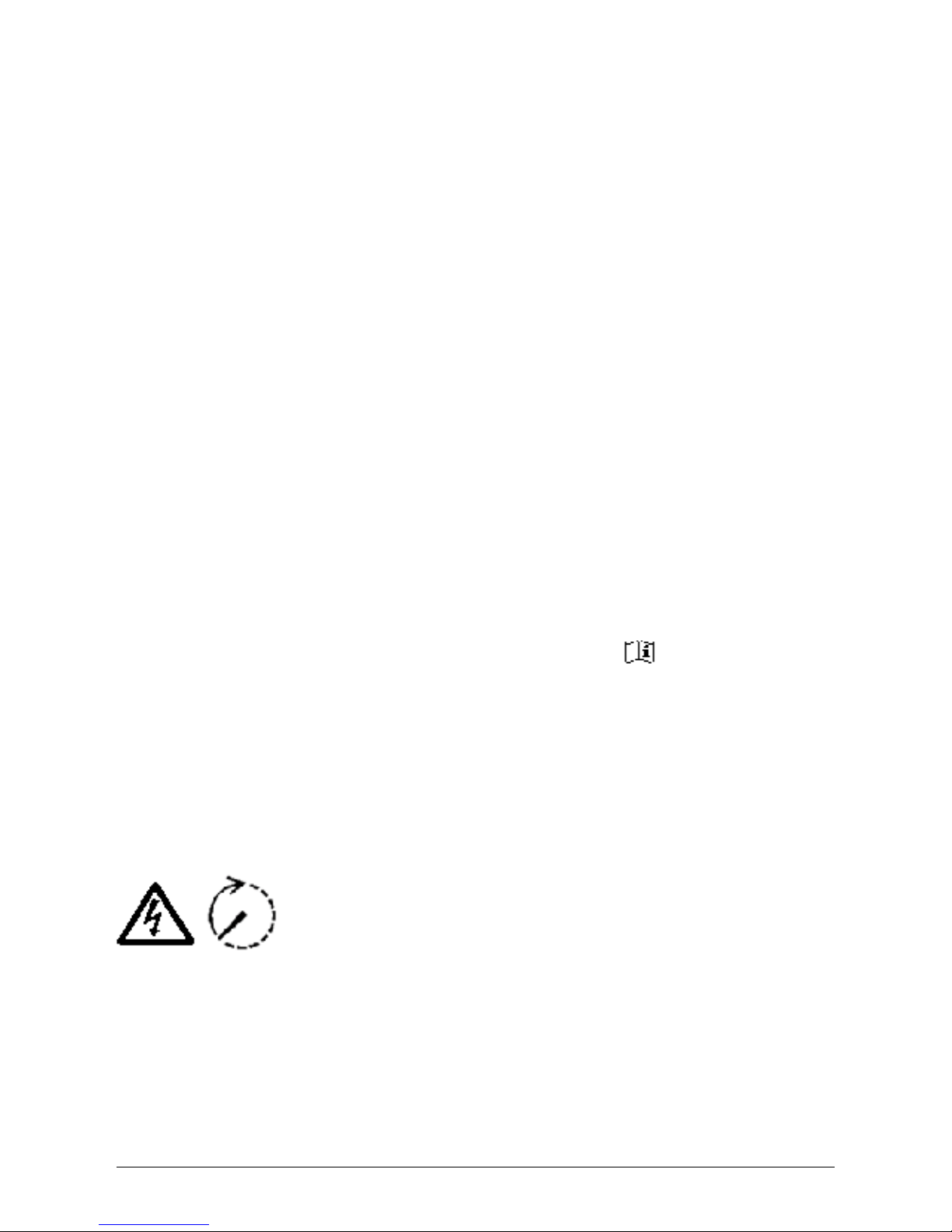
To avoid risk of electrical shock, do not open the solar inverter. The inverter
contains no user-serviceable parts. Opening the cover will invalidate the
warranty.
Dangerous voltage is present for 5 minutes after disconnecting all sources
of power.
Page 7

ENGLISH
5Operation and installation manual SOLIVIA 2.5 AP G3
3 Introduction
With this device you have acquired a solar inverter for connection of photovoltaic systems to the
grid. This solar inverter is characterized by its advanced housing design and state-of-the-art highfrequency technology, which enable the highest levels of efciency.
The solar inverter includes monitoring units, such as anti-islanding protection. The function of the
anti-islanding protection (automatic isolation point for in-plant generation systems) stipulates compliance with all specications required (see § 12).
The inverter is usable indoors and outdoors (IP65).
In the following technical description, the precise functions are explained to the installer, as well
as the user, which are required for the installation, operational start-up and handling of the solar
inverter.
4 System
The solar inverter converts direct current from the solar cells into alternating current. This enables
you to feed your self-produced solar energy into the public grid.
Thanks to efcient MPP tracking, maximum capacity utilization of the solar energy plant is ensured
even in the case of cloudy sky conditions.
The string concept means that PV modules are always connected in series (in a string) and/or that
strings with the same voltage are connected in parallel to the solar inverter with the aim of signicantly reducing the photovoltaic system’s cabling requirements.
The fact that the modules are connected in strings also means that the photovoltaic system can be
perfectly matched to the solar inverter’s input voltage range.
4.1 Data evaluation and communication
The integrated data display, processing and communication of the device enables easy operation of
the solar inverter. Monitoring of the operational status and signaling of operational failures are capable of being called up over the device display. The data interface enables the downloading of data
which can be evaluated with a PC system and guarantees continuous recording of operating data.
The best way of accessing this functionality is via the available accessories; comprehensive and
seamless solar inverter monitoring is ensured.
The data read-out over the integrated interface and the display is possible only in solar operation.
Page 8

6 Operation and installation manual SOLIVIA 2.5 AP G3
4.2 Technical structure of the solar inverter
A galvanical isolation of the solar inverter from the grid is achieved through a DC/AC converter with
an integrated high-frequency transformer. The photovoltaic voltage is adjusted so that the maximum
power output of the PV modules is also achieved with varying solar irradiation levels and temperatures (MPP-Tracking).
The MPP range of the solar inverter is between 150 V and 450 V. This facilitates the use of PV
modules by a variety of manufacturers. Measures must be taken to ensure that the maximum opencircuit voltage of 540 VDC (for Korea limited to 500 V only) is never exceeded. Please note that
the maximum open-circuit voltage will occur at the lowest temperatures anticipated. You will nd
more detailed information about temperature dependency in the data sheet of the PV modules. The
device’s power consumption is kept to a minimum.
The high-quality aluminum casing corresponds to protection class IP65 (water-jet-proof and dustproof) and is protected against weathering processes by surface re nement. The cooling characteristic pro le is designed so that operation of the inverter is possible with ambient temperatures
from -25°C to +70°C.
A cooling characteristic pro le is used for the removal of the power dissipation caused through the
voltage conversion. An internal temperature control protects the device against excessive temperatures in the interior of the solar inverter. In case of high ambient temperatures, the maximum
transferable power is limited.
The solar inverter is controlled by microcontrollers, which also implement interface communication
and the monitoring of values and messages on the display.
Two independent and redundant microcontrollers control the monitoring of the grid, which is consistent with the feed-in directives of your local utility company. This enables an installation of the solar
inverter in the in-house electrical grid.
Operator protection requirements are met by electrically isolating the grid from the PV module. The
electrical isolation between the grid and the PV module is equivalent to basic insulation. Maximum
operator protection is ensured by reinforced isolation between the grid, PV modules and accessible
interfaces (display, RS485 interface). Relevant standards concerning electromagnetic compatibility
(EMC) and safety are ful lled.
The solar inverter is functional in on-grid operation exclusively. An automated isolation point, which
is approved by a certi cation agency, guarantees secure disconnection in case of circuit isolation or
interruptions in power supply and avoids isolated operation.
The disconnection equipment allows for automatic isolation for in-plant generation systems of nominal power ≤ 4.6 kVA, with single-phase parallel feed-in through the solar inverter into the grid.
Page 9
ENGLISH
7Operation and installation manual SOLIVIA 2.5 AP G3
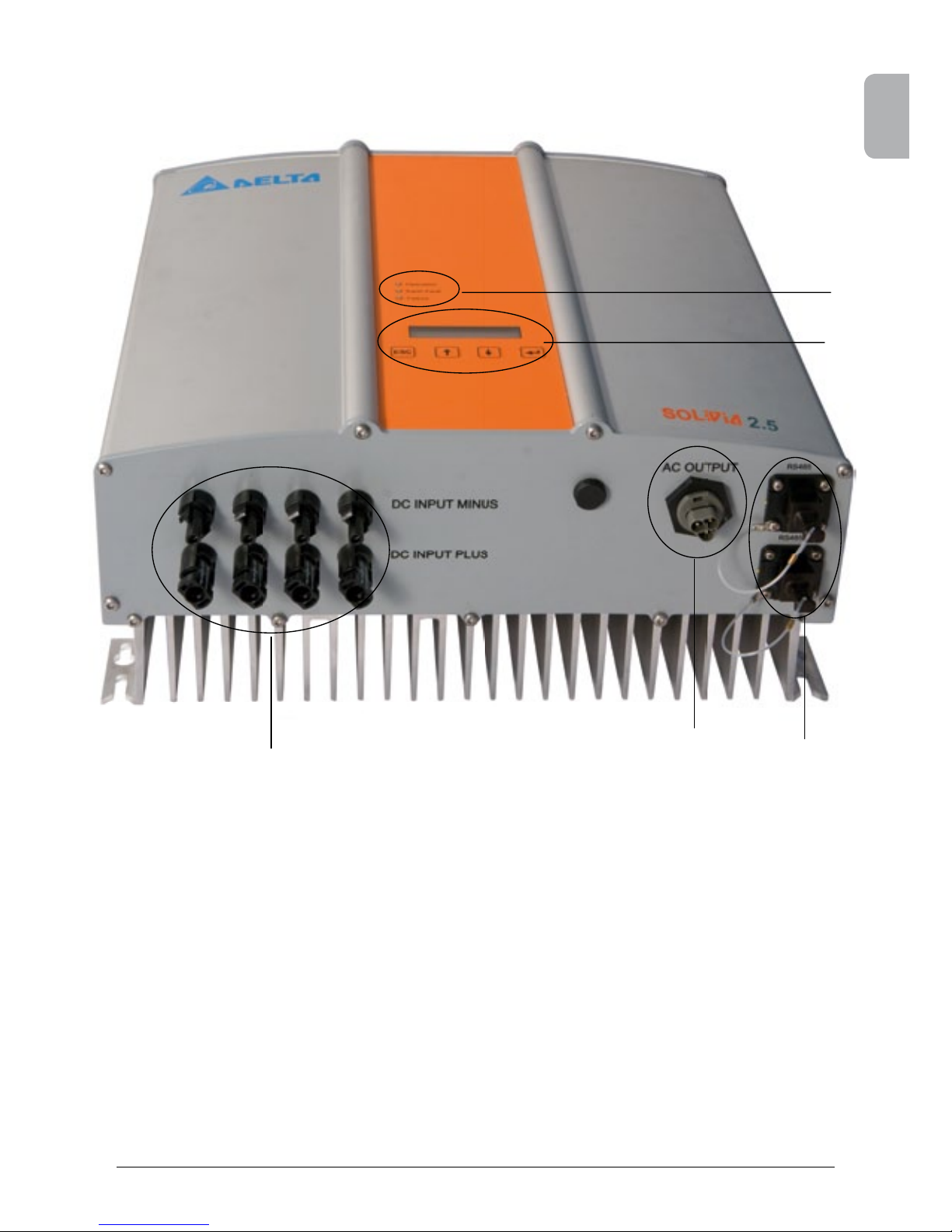
4.3 Equipment overview
(1) Connections for PV modules
(2) Grid connection
(3) Interface connection RS485 (EIA485)
(4) Display for status messages and keypad for operation
(5) Light-emitting diodes for operational status display
(1)
(4)
(5)
(2)
(3)
Page 10
8 Operation and installation manual SOLIVIA 2.5 AP G3
5 Installation
Installation and commissioning must only be carried out by qualied electrical experts.
The recommended local and national safety regulations and the technical interface conditions (TAB
2000), should be complied with.
To carry out an energy measurement, a meter must be attached between the grid feed-in point and
the solar inverter (in accordance with all local and national safety regulations).
By means of the integrated anti-islanding protection, the function of the recommended section
switch is fullled in accordance with all local and national safety regulations.
For details, please refer to § 9.
Caution: The secondary short-circuit current rating is increased at the transfer connection point to
the public electricity supply system by the nominal current of the connected solar inverter.
6 Installation of equipment
6.1 Installation location
• Install the device on a non-ammable support base.
• Avoid installation on resonating bodies (light construction walls etc.).
• Installation is possible both indoors and in protected outdoor areas.
• An increased ambient temperature can reduce the efciency of the PV system.
• Noise generation is possible (avoid installation in residential areas).
• Ensure legibility of the LEDs and the display (check read-off angle and installation height).
• Although the unit is tted with UV resistant components, direct exposure to sunlight should be
avoided.
• Despite having an IP65 enclosure and being certied in accordance with soiling category III, the
unit must not be allowed to become heavily soiled.
• Dusty conditions can impair the unit’s performance.
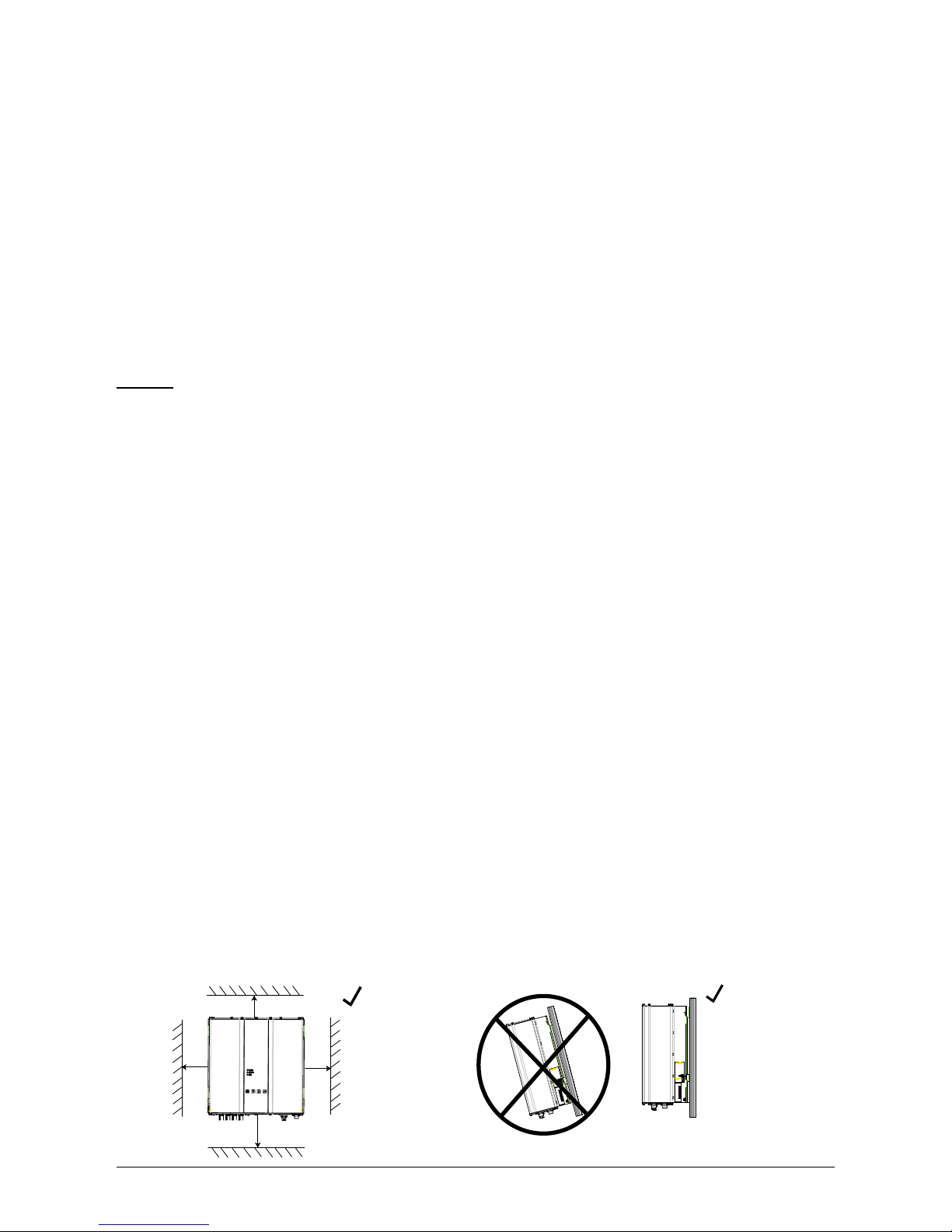
6.2 Minimum requirements
• Free convection around the solar inverter must not be impaired.
• For proper air circulation to dissipate heat, allow a clearance of approx. 10 cm to the side and
approx. 50 cm above and below the unit.
• The grid impedance requirement at the supply terminal is to be observed (cable length, cable
cross-section).
• The recommended installation position is to be adhered to (vertical).
• Unused DC connectors and interfaces must be sealed airtight with sealing plugs to ensure
protection class IP65 for the whole system (inverter & cables).
50 cm
10 cm
50 cm
10 cm
Wall
Wall
Page 11
ENGLISH
9Operation and installation manual SOLIVIA 2.5 AP G3
319.5
150
320
200
6.5
12
Ø
12.5
90
38
12
410 ± 0.5
6.3 Maintenance
Make sure that the device remains uncovered while in operation. To avoid the casing of the solar
inverter becoming soiled, it should be cleaned periodically.
User serviceable parts are not contained in the device. Under no circumstances should the solar
inverter be opened!
6.4 Installation
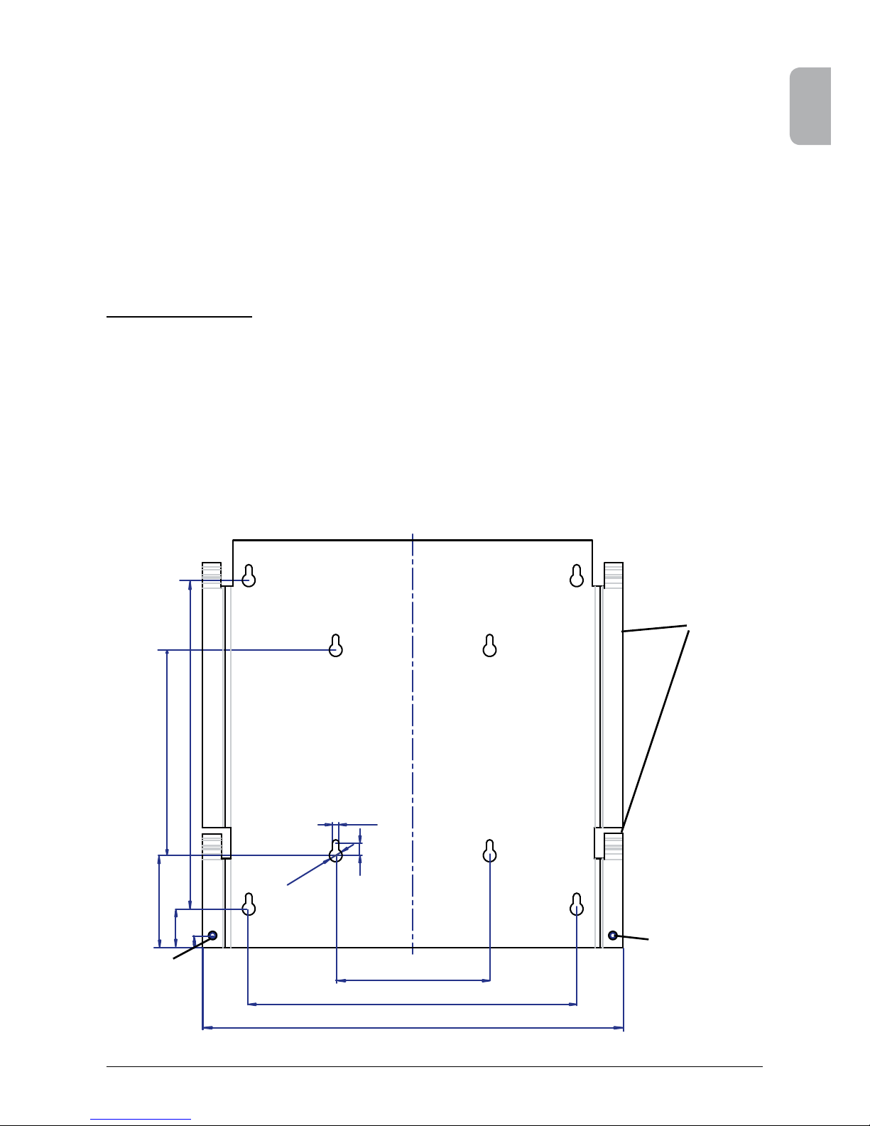
You should utilize the delivered mounting plate for problem-free installation of the solar inverter.
Installation to the wall should be implemented with the proper screws. Mount the wall bracket so that
the solar inverter only has to be simply attached. After that, the device is to be bolted on securely.
Assembly instructions
1. Mount the mounting plate with appropriate screws (max. Ø 6mm) into at least four of
the eight holes to x the wall bracket in place. You can employ the mounting plate as a
template for marking the positions of the boreholes.
2. As the solar inverter weighs 21.5 kg, it should be lifted out of the transport crate by at
least two persons.
3. Place the solar inverter onto the mounting plate with at least two persons.
4. Fasten the supplied mounting nuts and washers on the threaded bolt intended for secu ring the device.
5. Check that the solar inverter is securely sealed.
Mounting
plate
Locking screw
Locking screw
Page 12

10 Operation and installation manual SOLIVIA 2.5 AP G3
6.5 Ambient temperature
The solar inverter can be operated in an ambient temperature between -25°C to +70°C.
The device should be installed in a well-ventilated, cool and dry location.
6.6 Grid connection
The grid (AC output) is connected over a Wieland RST25i3S AC connector. You can nd the correct allocation on the screw-type terminal connection of the connector. The solar inverter must be
connected to the grid over a three-core line (L, N, PE). The connected AC line must be switched
potential-free before the disconnection or the insertion of the AC connector.
The connection to the Wieland AC connector must be made with a exible line and a conductor
cross section of min. 2.5 mm² to max. 4.0 mm².
An automatic circuit breaker is to be provided in the line L upstream of every device, with a nominal
current of 25 A and tripping characteristic type B or C (please refer to your local country installation
requirements and regulations for correct tripping characteristic type). In addition, attention is to be
paid to the selectivity of the fuse unit attached upstream of the automatic circuit breaker.
The solar inverter must be grounded via the AC connector’s PE conductor. To do this, connect the
PE conductor to the designated terminal. If you wish to integrate more than one inverter into the
installation, please proceed as illustrated in the drawings in the appendix.
Please note the cable length and the cable cross-section, due to the risk of undesirable temperature
rise and power losses.
The AC connector is protected from unintentional disconnection by a clip mechanism which can be
released with a screwdriver.
6.7 Connection of PV modules
Before the photovoltaic system is connected, the polarity of the PV voltage at the Multi-Contact connectors must be checked to ensure that it is correct.
The connection of the PV module is implemented using Multi-Contact MC4 connectors, where the
DC negative pole is located on the connector upper row and the DC positive pole on the connector
lower row. The connectors are coded to prevent you from accidentally plugging them into the wrong
terminal.
Please ensure the following at all times:
• That there is never any risk of anyone coming into contact with the solar inverter connection
terminals, due to the risk of dangerous voltages across them.
• That under no circumstances are the PV modules to be disconnected from the solar inverter under
load. If a disconnection should be necessary, rst switch the grid off so that the solar inverter
cannot absorb any further power. Next, open the upstream DC disconnector.
The maximum input voltage of the solar inverter is 540 V (for Korea limited to 500 V only). The
maximum current load of each individual Multi-Contact MC4 connector is 18 A.
Page 13
ENGLISH
11Operation and installation manual SOLIVIA 2.5 AP G3
The solar inverter has an insulation and grounding monitoring on the DC side. The options can be
congured in the Setup menu “S -> Solar ISO / GND” (see § 7.3.7.1).
The insulation monitoring has two modes:
• ISO-ON-Error (the solar inverter is disconnected from the grid in the event of an insulation
fault)
• ISO-ON-Warning (the solar inverter indicates the fault but is not disconnected from the grid).
Deltas solar inverters are factory-set to ISO-ON-Warning mode on delivery.
The grounding monitoring has two modes:
• PV+ grounding (grounding monitoring of the positive pole of the PV generator)
• PV- grounding (grounding monitoring of the negative pole of the PV generator).
In these modes the solar inverter remains in feed-in operation and will not be disconnected from the
grid in case of a fault. The error message “PV+ grounding fault” or “PV- grounding fault” will appear
on the display.
If you need to connect the positive or negative pole of the PV system to meet requirements set
out by the module manufacturer, you can do this. Earth continuity must be implemented close to
the inverter. We suggest using Deltas grounding kit “Grounding Set A Solar” (EOE99000275). The
grounding connection is monitored and should be congured in the Setup menu (see above).
Alternatively, it is possible to turn off the insulation- and grounding monitoring:
• ISO / GND OFF.
CABLE
COUPLER
POLARITY
WIRE SIZE
2.5 MM
2
(AWG 14)
WIRE SIZE
4.0 MM2 - 6.0 MM²
(AWG 12-10)
FEMALE
CABLE
COUPLER
MALE CABLE
COUPLER
MULTI-CONTACT
ORDER NUMBER
Plus
coupler
• •
32.0010P0001-UR
32.0012P0001-UR
Minus
coupler
• •
32.0011P0001-UR
32.0013P0001-UR
Plus
coupler
• •
32.0014P0001-UR
32.0016P0001-UR
Minus
coupler
• •
32.0015P0001-UR
32.0017P0001-UR
Required cable coupler types for DC cable connection to inverter:
Page 14
12 Operation and installation manual SOLIVIA 2.5 AP G3
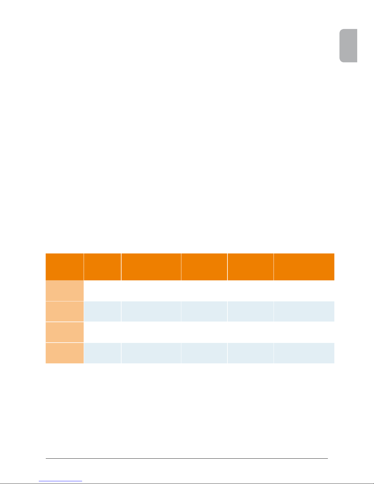
6.7.1 Output power over PV voltage
150 VDC
200 VDC 250 VDC
300 VDC
350 VDC 400 VDC 450 VDC
500
2
7
0
0
W
2
900
W
3
W
W
W
W
W
W
W
210 VAC 230 VAC 250 VAC
270 VAC
6.7.2 Output power over AC voltage
Page 15
ENGLISH
13Operation and installation manual SOLIVIA 2.5 AP G3
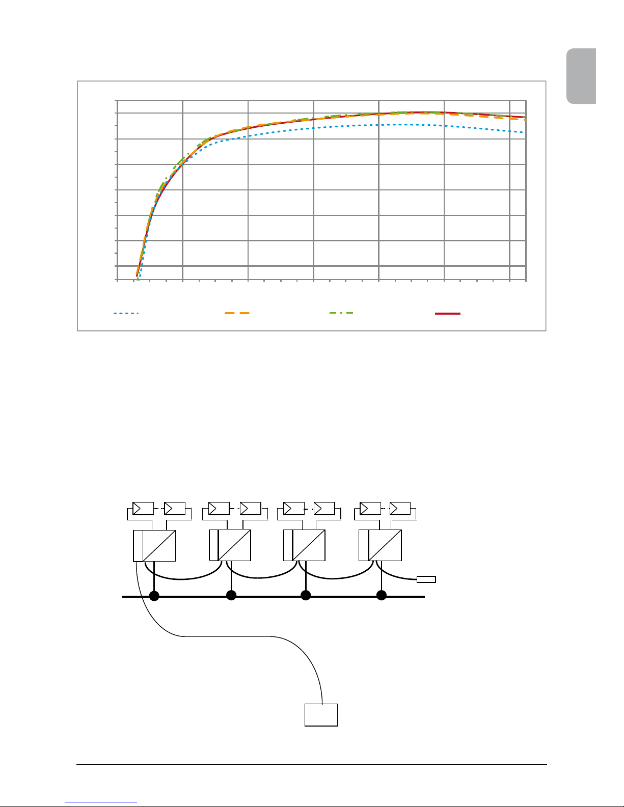
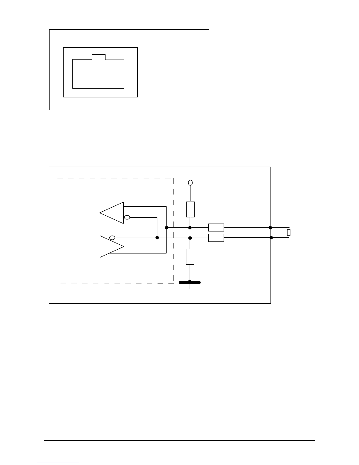
6.8 Interface connection RS485 (EIA485)
The interfaces not used must always be closed off. In case of utilization of an interface, only the
counterpart tting on the interface connector is to be employed.
Mating connector supplier HARTING Deutschland GmbH & Co. KG (P.O. 2451, 32381 Minden;
Germany; www.harting.com).
Order designation: 09 45 145 1510, Cable Manager Blue IP67 Push-Pull Data Plug
09 45 145 1500, Cable Manager White IP67 Push-Pull Data Plug
-
~
-
~
-
~
-
~
220 V / 230 V
House connection line
RS485 (EIA485) - Connection
Datalogger
RS485 (EIA485)
terminating resistor
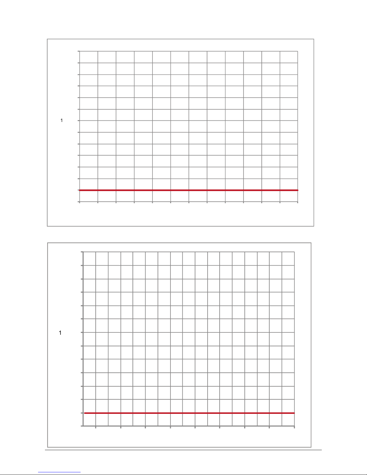
6.7.3 Efciency
The best efciency of the solar inverter is obtained at input voltages >250 V.
84 %
86 %
88 %
90 %
92 %
94 %
96 %
0 W
400 W
800 W
1200 W
1600 W
2000 W
2400 W
2500 W @ 150 V
2500 W @ 250 V
2500 W @ 350 V
2500 W @ 450 V
Page 16
14 Operation and installation manual SOLIVIA 2.5 AP G3
8
1
Pin
1 Reserved
2 Reserved
3 Reserved
4 GND (RS485)
5 Reserved
6 RX_B (RS485)
7 TX_A (RS485)
8 Reserved
Top View
Connector pin assignment RS485 (EIA485)
+5V
Reserved
Reserved
0R
0R
TX_A
RX_B
GND
Pin 7
Pin 6
100 ... 150
Ohm, 0,25W
When several devices are connected in series and the total length of the data line measures 2 m or
more, the following option is available for terminating the RS485 (EIA485) interface:
Page 17
ENGLISH
15Operation and installation manual SOLIVIA 2.5 AP G3
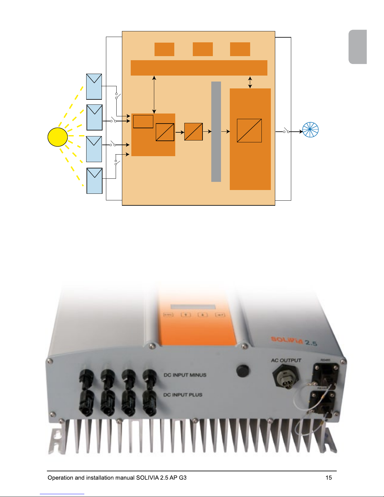
6.9 Electrical connection and operational start-up
The electrical connection is utilized on this solar inverter using the connector contacts which are
attached to the casing. In no case must the device be opened!
Power
controller
Antiislanding
protection
Communication
Operating- and system control
MPPTracker
-
-
Booster
-
-
Isolation
DC-Bus
~
Solar inverter
DC
DC
DC
DC
String A
String B
String C
String D
AC
Public
grid
Page 18
16 Operation and installation manual SOLIVIA 2.5 AP G3
In order to connect the device electrically, the following procedures must be followed:
1. DC connection: First, connect the PV module strings to the DC disconnector (not included in
the scope of delivery).
2. Connect the DC disconnector to the solar inverter (ensure correct polarity).
3. AC connection: Please install the Wieland AC mating connector to the AC output cable and then
put the AC connector to the solar inverter. Please make sure, that the sleeve nut is properly
xed and tighten.
4. Before switching on the power, check all feeders and connections one last time.
5. Close the DC disconnector.
6. Close the circuit breaker on the AC output side.
7. In case of suf cient PV voltage (UPV > 150 V), the device now goes into the start-up mode.
8. In case of a new installation the time and date have to be set in sub-menu S (Setup) (see § 7.3.7).
All unoccupied connectors and interfaces must be sealed using the provided sealing
plugs.
6.10 Setup / settings
The default display language for solar inverters leaving the Delta factory is set to English.
After connecting to correct DC voltage and running through self-test, you will be asked to specify
the network ID and to select the desired country (see § 7.3.7.2) (countries available: Australia,
Australia PL
1)
, China, India, Korea and Taiwan).
The selection has to be con rmed another time by the user. Once con rmed, the network ID and
the country selection are stored to the controller memory – and the solar inverter is ready for
operation.
Please note that the enter keys on the display are locked, if there is no input entry within 5
minutes. To unlock the enter keys, you need to switch off the DC voltage and then switch it on
again.
1) In certain states in Australia, power limitation is required.
• With power limitation, the output (AC) power of SOLIVIA 2.5 AP G3 will be as followed :
Max power: 2490 W
Nominal power: 2350 W
• To activate power limitation, please select dedicated country “Australia PL” (Installed settings are password
protected):
Select unit ID = [1] & press <ENTER> key
Select country = [Australia PL] & press <ENTER> key
Con rm country selection by pressing <ENTER> key
• The following label that is enclosed in the box of the inverter MUST be sticked next to the model label:
• To check if power limitation has been activated, please go to the menu S (Setup) and press the „UP“ or
„DOWN“ buttons to nd the following display message:
at maximal output power of: 2.49kW
For Australia PL
This product has been power limited
S -> Country Set
AU L
Down
Up
AUstralia Limitation
Page 19
ENGLISH
17Operation and installation manual SOLIVIA 2.5 AP G3
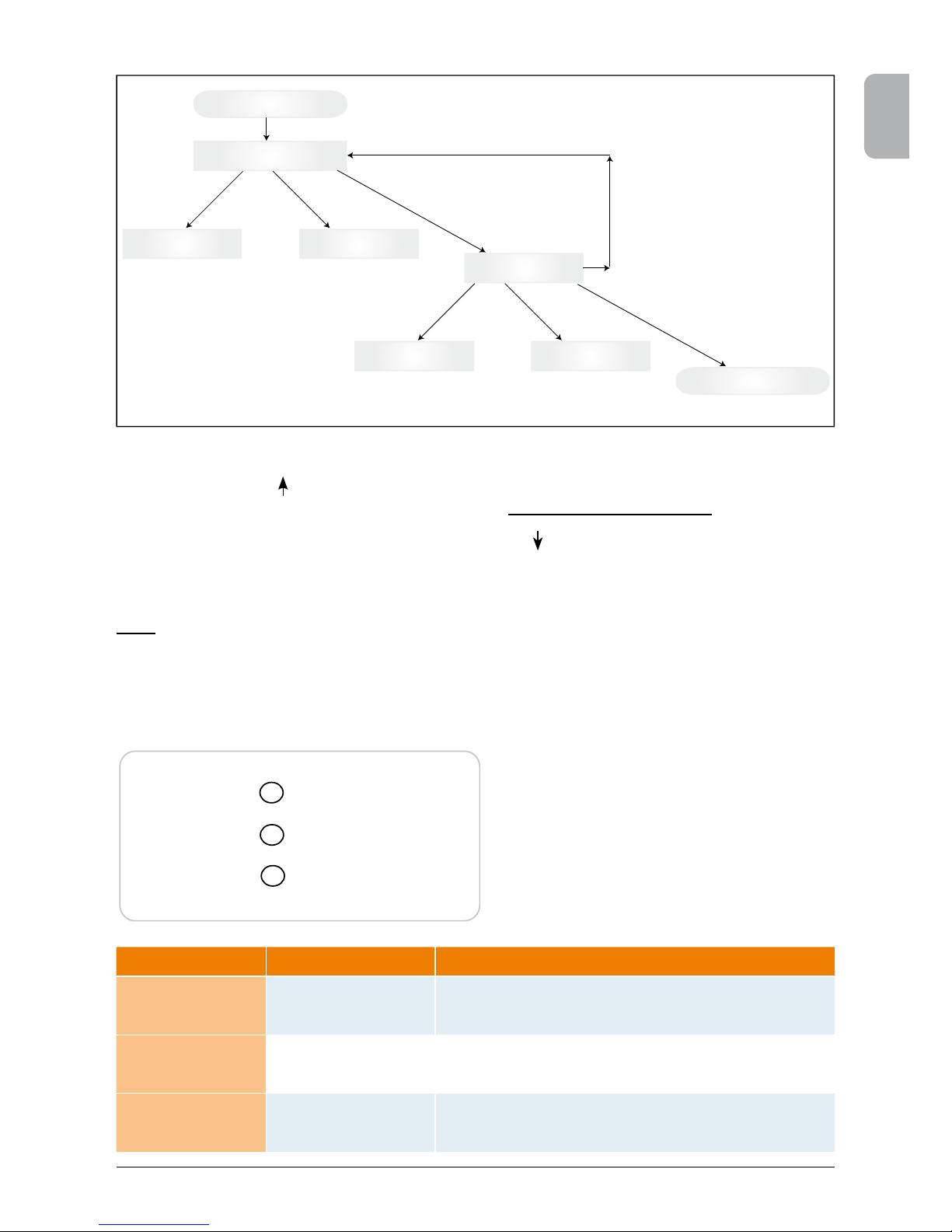
Country selection
Increase network ID Decrease network ID
Down *
Up *
Enter network ID
ENTER *
ESC *
Select country
Next country Country before
Down *
Up *
ENTER *
Normal mode
* Timeout if no key is pressed (within 5 minutes)
Operation (A)
Earth Fault (B)
Failure (C)
• LED (A), green: „Operation“ displays the
operational state.
• LED (B), red: „Earth Fault“ displays an insula tion resistance fault or PV grounding (GND)
fault on the DC side.
• LED (C), yellow: „Failure“ displays existing
faults internally or externally and whether the
grid feed-in operation has been interrupted.
6.11 LED operation and fault display
Three light-emitting diodes (LEDs), which display the operational state of the solar inverter, are
attached on the front:
Please note, that once the country has been selected and con rmed, it is only possible to change
the country by following the steps as listed below:
1. Please click ESC + for few seconds to get the key information.
2. Provide the key code to the Solar Support Team at support@solar-inverter.com to get the PIN
code (valid for one use only!).
3. Once you get the PIN code, you need to press ESC + .
4. Then, you will be asked to insert the PIN code and to con rm it twice.
5. After con rmation, you will then be able to select the desired country.
Note: These steps must be executed without interruption. Otherwise, you will stay in the country
selection mode.
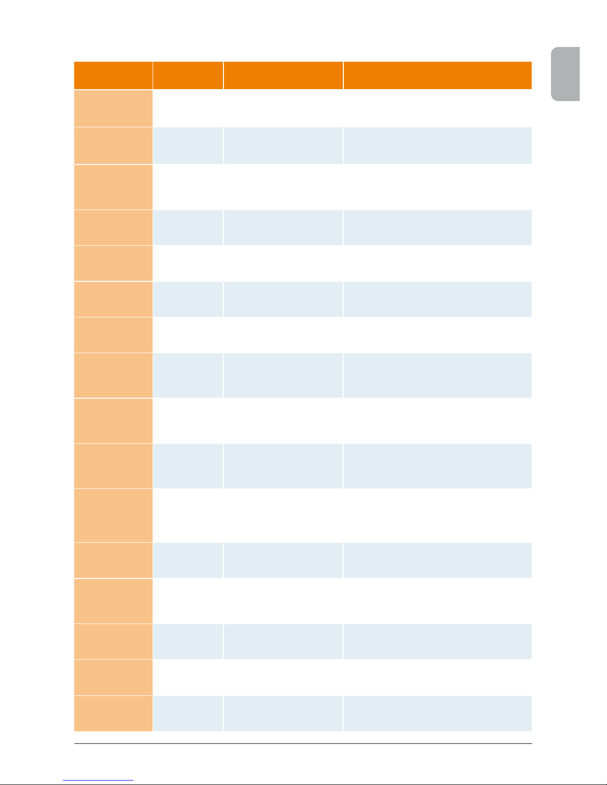
LED STATUS OPERATIONAL STATE EXPLANATION
green: <off>
red: <off>
yellow: <off>
Night disconnection.
The input voltage (UPV) is lower than 100 V.
The solar inverter is not feeding power to the grid.
green: <on>
red: <on>
yellow: <on>
Initialization.
Input voltages:
UPV: 100 V to 150 V
(self test ongoing).
green: < ashes>
red: <off>
yellow: <off>
Input- and grid monitoring.
Starting conditions are tested.
Page 20
18 Operation and installation manual SOLIVIA 2.5 AP G3
7 Operating concept
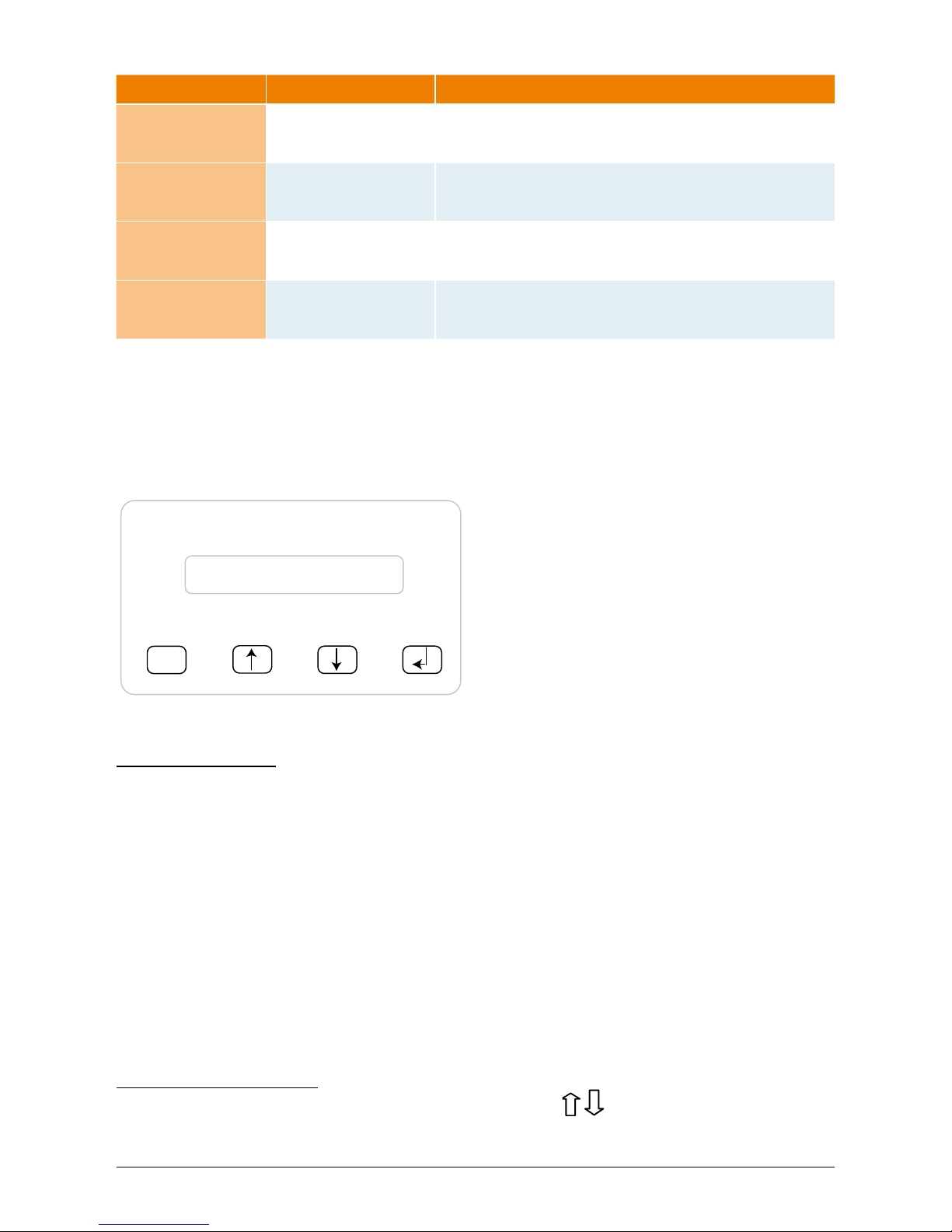
7.1 The display
The display on the device indicates varied information. The enter keys are used for the adjustment
of the device and for the retrieval of information. The indicated data can deviate with a tolerance of
up to 5%.
ESC
(A) (B) (C) (D)
7.2 Navigation in the display
Lighting of the display
After pressing the ENTER key in automatic operation, the display lighting is switched on. If no key
is pressed within 30 seconds, the display lighting automatically goes out. The setup menu enables
selection between continuous or automatic lighting. Through pressing the ENTER key, the display
lighting is switched on again.
Key (A), ESC: To switch from the menu
items to the main menu and
to exit each sub-menu.
Key (B) and (C): For scrolling in the individual
menu items and/or carrying
out adjustments in the setup
menu.
Key (D), ENTER: ENTER key for changing into
the menu levels and for input
acknowledgement in the
setup menu.
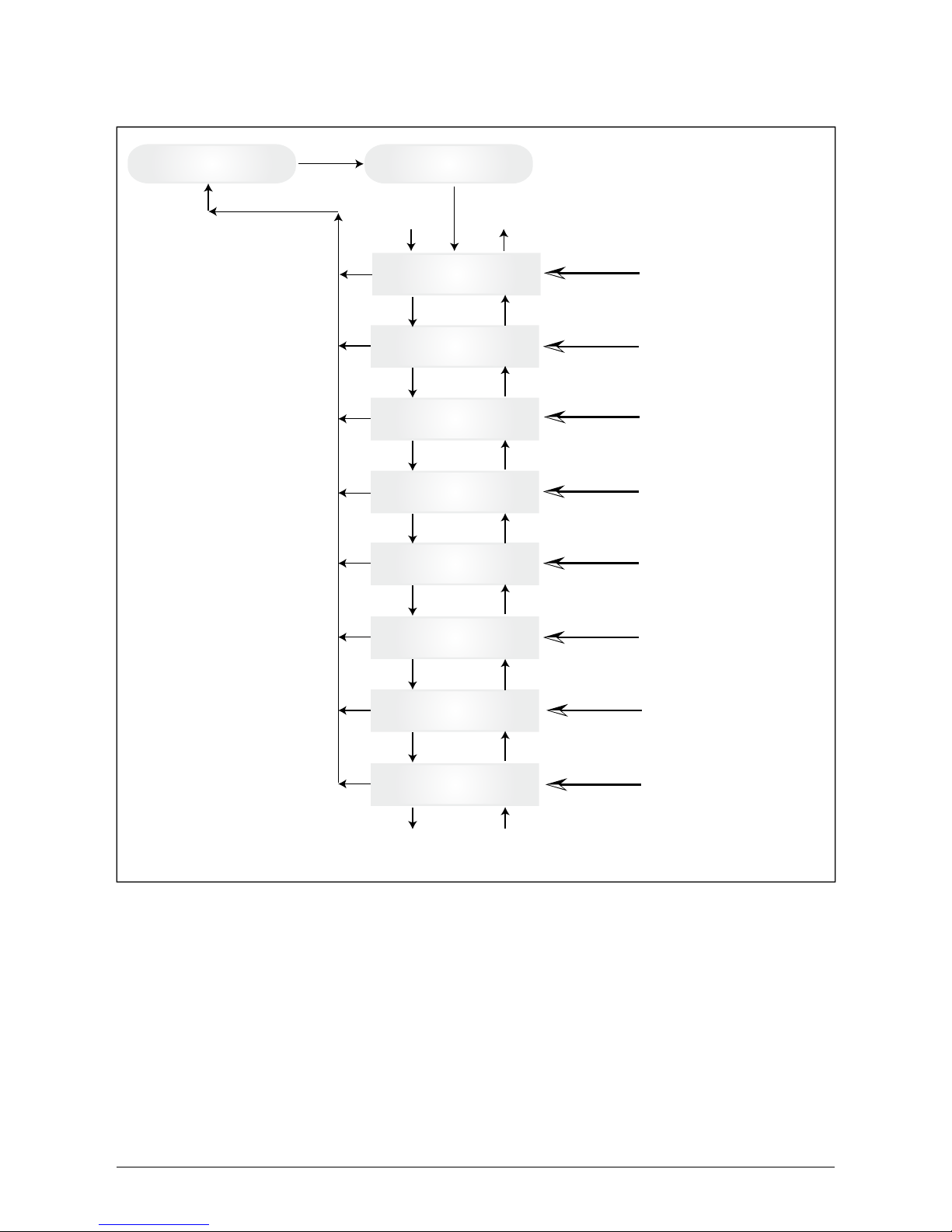
7.3 Main menu
The main menu consists of 7 menu items which are subdivided into submenus:
• Menu N (Now)
• Menu D (Day)
• Menu W (Week)
• Menu M (Month)
• Menu Y (Year)
• Menu T (Total)
• Menu S (Setup)
Handling of the menu items:
You can scroll the main menu by activating the selector keys
.
Press the ENTER key to select the submenus. In order to exit the menus again, activate the ESC
key.
LED STATUS OPERATIONAL STATE EXPLANATION
green: <on>
red: <off>
yellow: <off>
Feed-in operation.
Normal operational state:
UPV: 150 V to 450 V.
green: <off>
red: <on/off>
yellow: <on/off>
Equipment fault.
Internal or external fault
(interrupted feed).
See also display messages!
green: <off>
red: <on/off>
yellow: <on>
General error
condition.
Solar inverter is not connected to the grid.
No power is delivered.
See also display messages!
green: <on/off>
red: <on/off>
yellow: <ashes>
Warning message.
You can carry on using the solar inverter.
See also display messages!
Page 21

ENGLISH
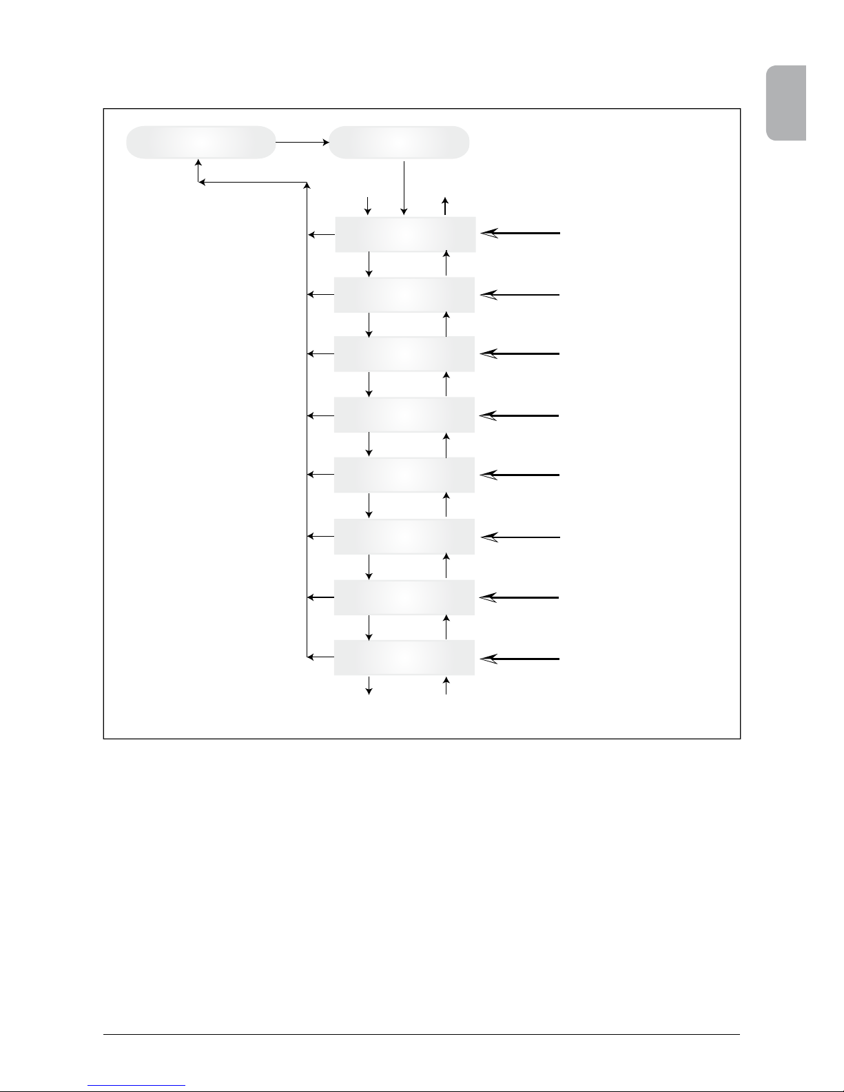
19Operation and installation manual SOLIVIA 2.5 AP G3
User menu
Menu N - Now (act data)
Menu D - Day statistic
Menu W - Week statistic
Menu M - Month statistic
Menu Y - Year statistic
Menu T - Total statistic
Menu S - Setup inverter
Down
Down
Down
Down
Down
Down
Up
Up
Up
Up
Up
Up
Down to 2
1
Up to 1
2
Submenu N - Now
Submenu D - Day
Submenu W - Week
Submenu M - Month
Submenu Y - Year
Submenu T - Total
Submenu S - Setup
ESC
ESC
ESC
ESC
ESC
ESC
ESC
ENTER
ENTER
ENTER
ENTER
ENTER
ENTER
ENTER
Remarks:
ESC in main menu jumps to first entry of
corresponding sub menu
Page 22
20 Operation and installation manual SOLIVIA 2.5 AP G3
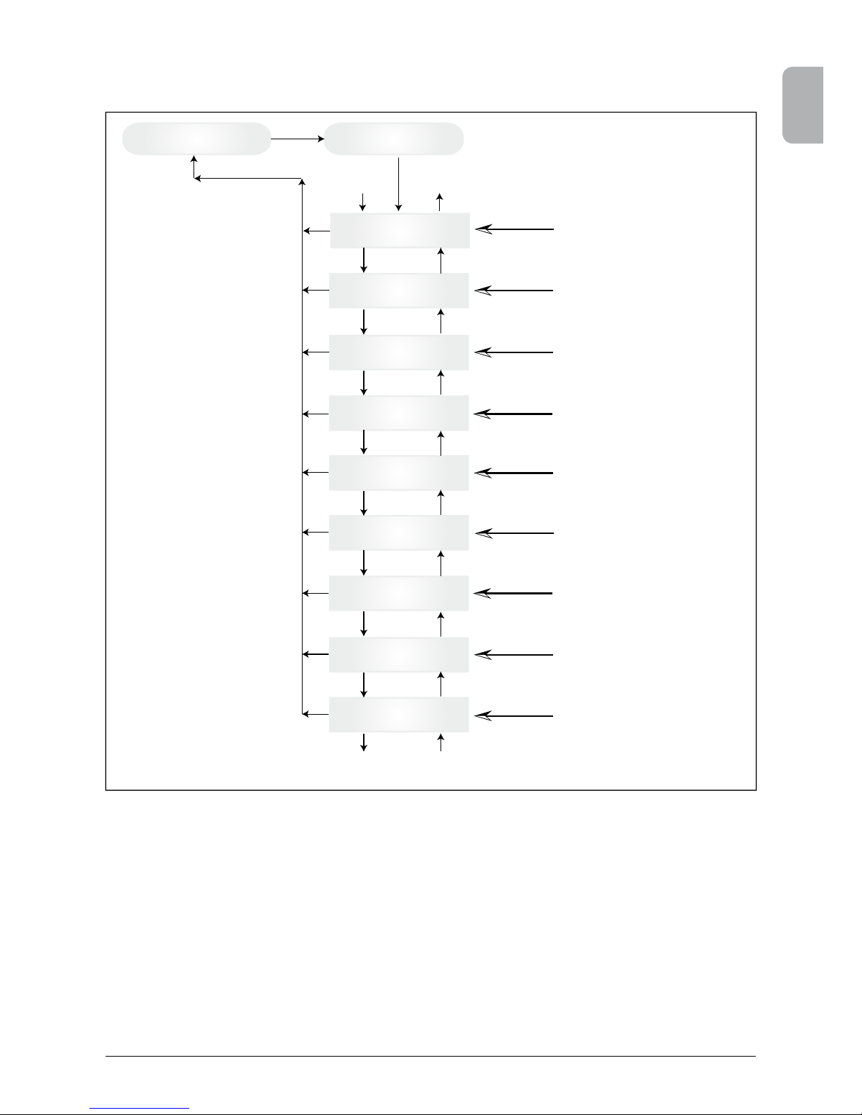
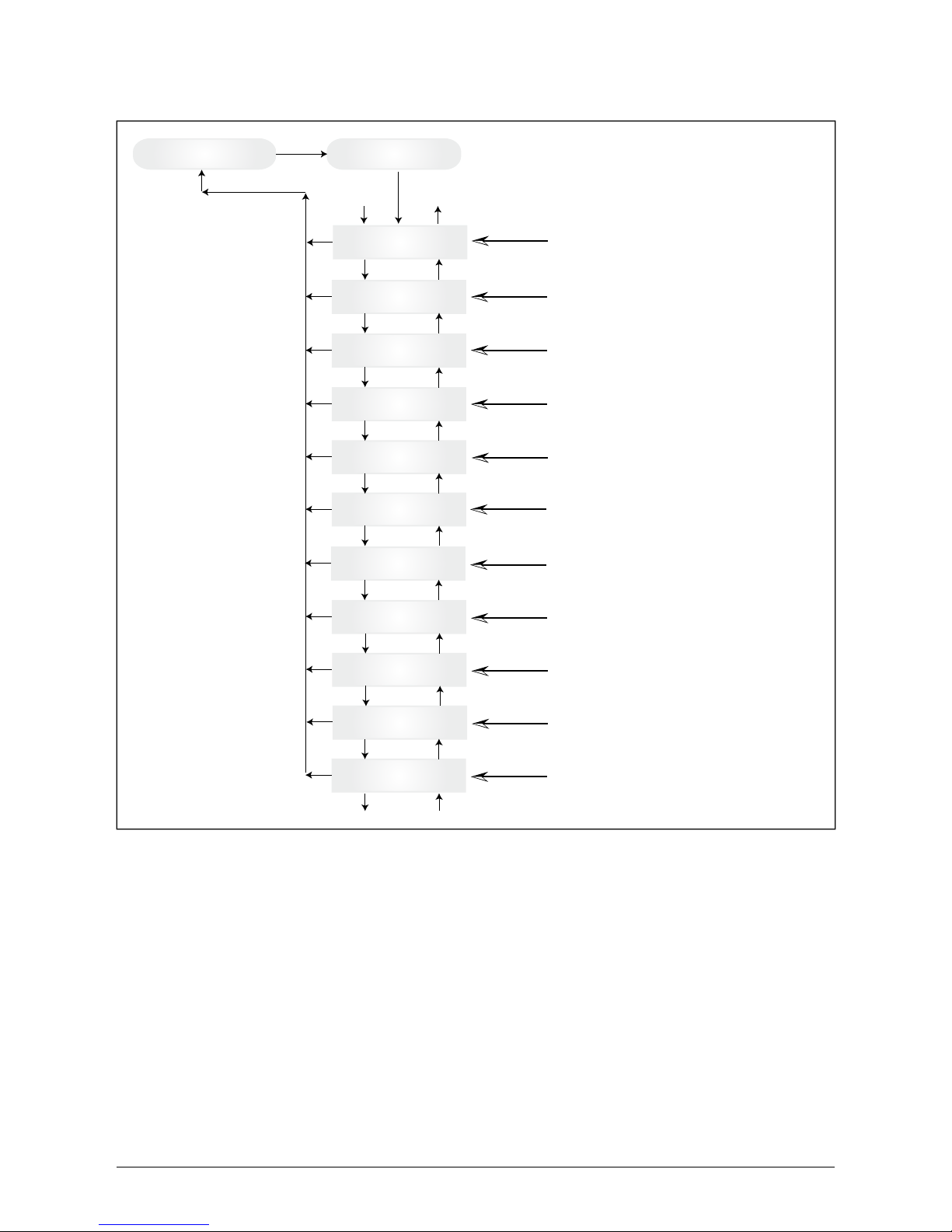
7.3.1 Submenu N (Now)
This menu item displays the active values.
Main menu N - Now
actual data
N -> AC-Power Value (W)
N -> AC-Voltage Value (V)
N -> AC-Current Value (A)
N -> AC-Frequency
Value (Hz)
N -> PV-Voltage Value (V)
N -> PV-Current Value (A)
N -> Time (HH:MM:SS)
N -> Date
(WD.DD.MM.YYYY)
Down
Down
Down
Down
Down
Down
Down
Up
Up
Up
Up
Up
Up
Up
Down to 2
1
Up to 1
2
Submenu N - Now
ESC
ESC
ESC
ESC
ESC
ESC
ESC
Remarks:
ESC in main menu N jumps to first entry of
sub menu N
ESC
ENTER
Display of the
active output power
Display of the active
output voltage
Display of the active
output current
Display of the active
mains frequency
Display of the active
PV cell voltage
Display of the active
PV cell current
Display of the
current time
Display of current day
of the week and date
Page 23
ENGLISH
21Operation and installation manual SOLIVIA 2.5 AP G3
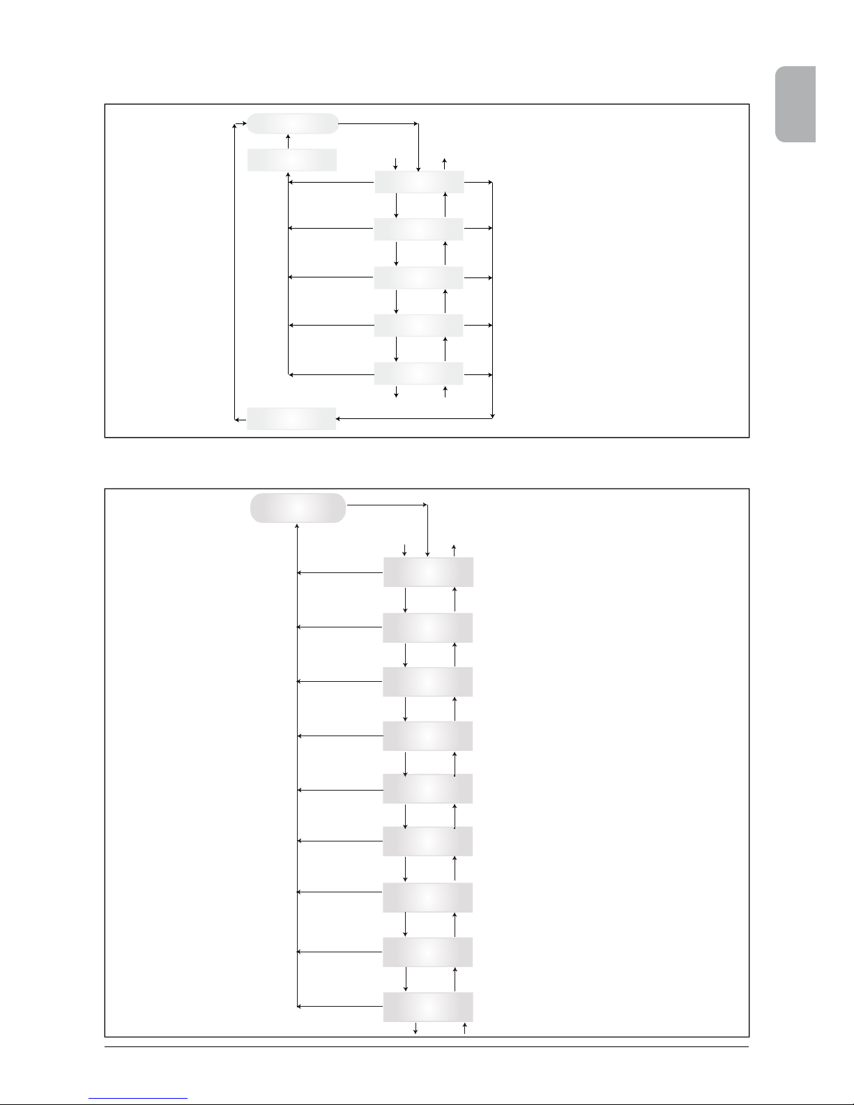
7.3.2 Submenu D (Day)
This menu item displays the daily values for the grid feed.
Main menu D - Day statistic
D -> Energy Value (Wh)
D -> AC-Revenue Value
(AUD / Won)
D -> AC-Power-Max
Value (W)
D -> AC-Volt-Max
Value (V)
D -> AC-Volt-Min
Value (V)
D -> AC-Curr-Max
Value (A)
D -> AC-Freq.-Max
Value (Hz)
D -> Runtime Value (Min)
Down
Down
Down
Down
Down
Down
Down
Up
Up
Up
Up
Up
Up
Up
Down to 2
1
Up to 1
2
Submenu D - Day
ESC
ESC
ESC
ESC
ESC
ESC
ESC
Remarks:
ESC in main menu D jumps to first entry of
sub menu D
ESC
ENTER
D -> AC-Freq.-Min
Value (Hz)
ESC
Down
Up
Display of the daily
energy gain
Display of the daily revenue
Display of the daily
maximum output power
Display of the daily max.
output voltage
Display of the daily min.
output voltage
Display of the daily
maximum output current
Display of the daily
maximum output frequency
Display of the daily
minimum output frequency
Display of the daily operating
time of the solar inverter
Page 24
22 Operation and installation manual SOLIVIA 2.5 AP G3
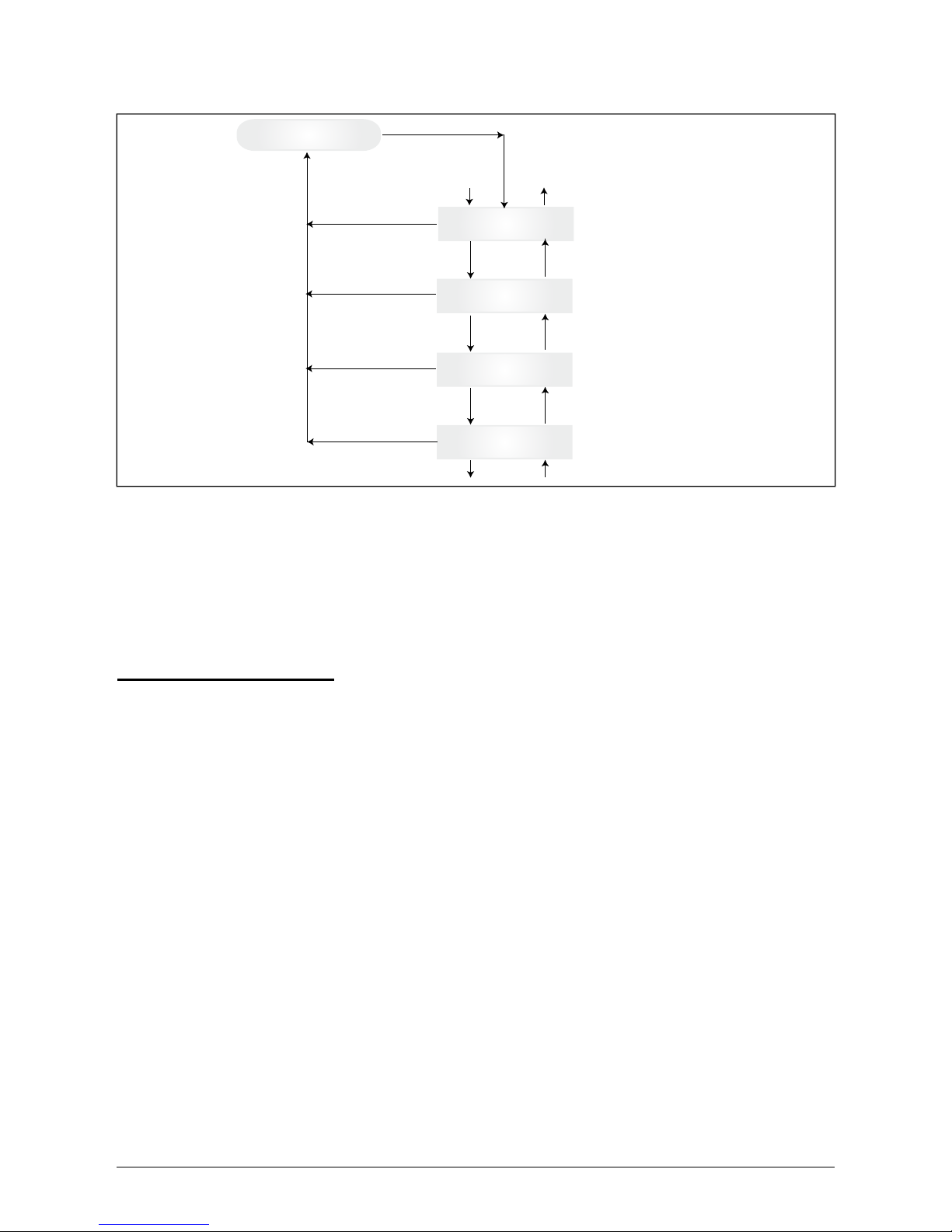
7.3.3 Submenu W (Week)
This menu item displays the average values of the current week.
Main menu W - Week statistic
W -> Energy Value (kWh)
W -> AC-Revenue
Value (AUD / Won)
W -> Runtime Value (h)
Down
Down
Up
Up
Down to 2
1
Up to 1
2
Submenu W - Week
ESC
ESC
Remarks:
ESC in main menu W jumps to first entry of
sub menu W
ESC
ENTER
Display of the weekly
energy gain
Display of the weekly revenue
Display of the weekly operating
time of the solar inverter
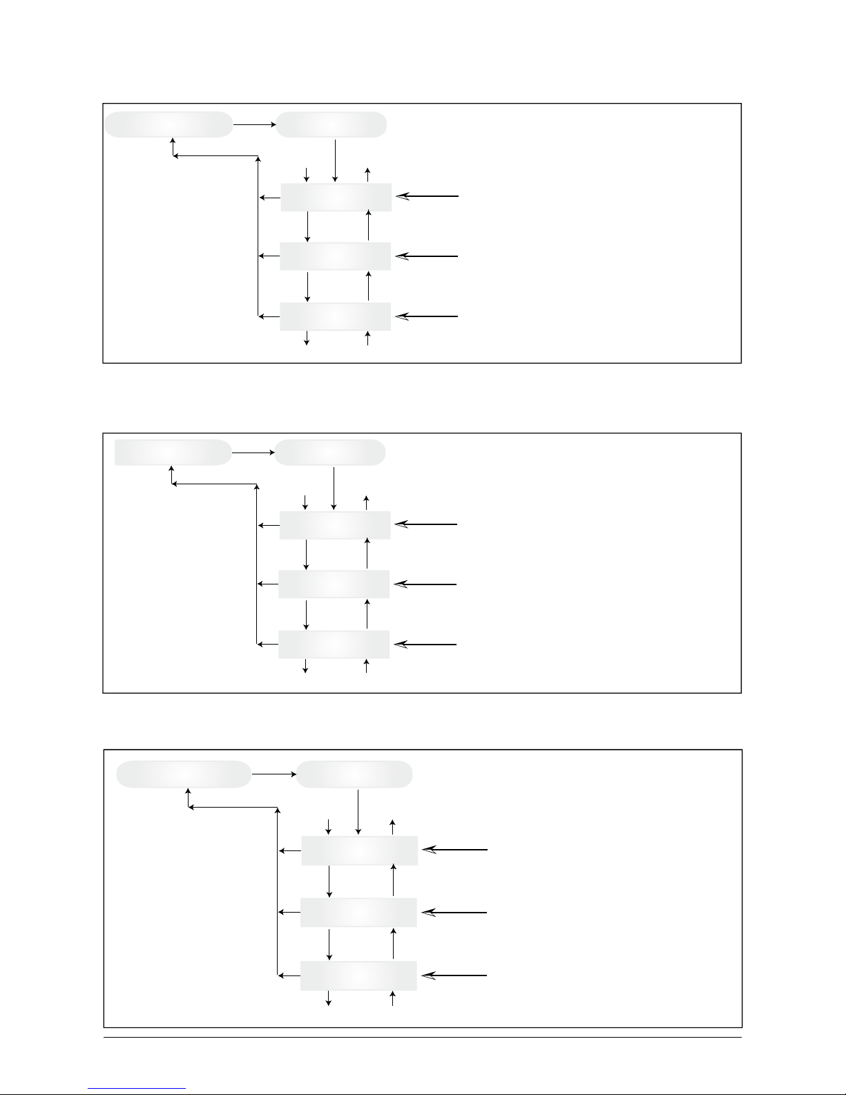
7.3.4 Submenu M (Month)
This menu item displays the average values of the current month.
M -> Energy Value (kWh)
M -> AC-Revenue
Value (AUD / Won)
M -> Runtime Value (h)
Down
Down
Up
Up
Down to 2
1
Up to 1
2
Submenu M - Month
ESC
ESC
Remarks:
ESC in main menu M jumps to first entry of
sub menu M
ESC
ENTER
Display of the monthly
energy gain
Display of the monthly revenue
Display of the monthly operating
time of the solar inverter
7.3.5 Submenu Y (Year)
This menu item displays the average values of the current year.
Main menu Y - Year statistic
Y -> Energy Value (kWh)
Y -> AC-Revenue
Value (AUD / Won)
Y -> Runtime Value (h)
Down
Down
Up
Up
Down to 2
1
Up to 1
2
Submenu Y - Year
ESC
ESC
Remarks:
ESC in main menu Y jumps to first entry of
sub menu Y
ESC
ENTER
Display of the annual
energy gain
Display of the annual revenue
Display of the annual operating
time of the solar inverter
Page 25
ENGLISH
23Operation and installation manual SOLIVIA 2.5 AP G3
7.3.6 Submenu T (Total)
This menu item shows cumulated and maximum/minimum values since rst use.
Main menu T - Total statistic
T -> Energy Value (kWh)
T -> Revenue Value
(AUD / Won)
T -> PV-Vol. Max
Value (V)
T -> PV-Cur. Max
Value (A)
T -> PV-Pow. Max
Value (W)
T -> Isolation Max
Value (kOhm)
T -> Isolation Min
Value (kOhm)
T -> Runtime Value (Min)
Down
Down
Down
Down
Down
Down
Down
Up
Up
Up
Up
Up
Up
Down to 2
1
Up to 1
2
Submenu T - Total
ESC
ESC
ESC
ESC
ESC
ESC
ESC
Remarks:
ESC in main menu T jumps to first entry of
sub menu T
ESC
ENTER
Up
Display of the total
energy gain
Display of the total
revenue
Display of the max.
PV cell voltage
Display of the max.
PV cell current
Display of the max.
PV cell power
Display of the largest
insulation resistance
Display of the smallest
insulation resistance
Display of the total operating
time of the solar inverter
Page 26
24 Operation and installation manual SOLIVIA 2.5 AP G3
7.3.7 Submenu S (Setup)
This menu item is used for changing the presettings of the solar inverter.
Main menu S - Setup
S -> LCD-Contrast
0 ... 9
S -> LCD-Backlight
Auto / On
S -> Menu-Mode
Now ... Setup
S -> Cash per kWh Value
(AUD / Won)
S -> ID-Number
001 ... 254
S -> Solar ISO / GND
S -> Baudrate
2400 ... 38400
Down
Down
Down
Down
Down
Down
Up
Up
Up
Up
Up
Down to 2
1
Up to 1
2
Submenu S - Setup
ESC
ESC
ESC
ESC
ESC
ESC
ESC
ENTER
Up
S -> Time (HH:MM:SS)
Down
ESC
Up
S -> Date
(WD.DD.MM.YYYY)
Down
ESC
Up
S -> Firmware
Down
ESC
Up
Adjustment of the firmware
Adjustment of the brightness of
the LCD display between 0 ... 9
Adjustment of the LCD
background lighting
Selection of the start menu
on restart of the device
Entry of feed-in remuneration in AUD / Won per kWh
Input of the ID number of the solar inverter
Adjustment of the baud rate
between 2400 ... 38400 Baud
Adjustment of the internal clock
Adjustment of current day of the week and date
ISO / GND Setup Menu
S -> Country settings
Name of country
ESC
Down
Adjustment of the country parameters
Up
Page 27
ENGLISH
25Operation and installation manual SOLIVIA 2.5 AP G3
7.3.7.1 Submenu S: Solar ISO / GND
More detailed information on the Solar ISO / GND menu within the submenu S (Setup).
Submenu Setup
Solar ISO / GND
S -> Solar ISO / GND
ISO ON-Warning
S -> Solar ISO / GND
ISO ON-Failure
S -> Solar ISO / GND
ISO GND-OFF
S -> Solar ISO / GND
PV+ grounded
S -> Solar ISO / GND
PV- grounded
Down
Down
Down
Down
Up
Up
Up
Up
Down to 5
6
Up to 6
5
ESC
ESC
ESC
ESC
ESC
ENTER
Use old setting
ENTER
ENTER
ENTER
ENTER
ENTER
Use new value
7.3.7.2 Submenu S: Country settings
More detailed information on the country settings menu within the submenu S (Setup).
Submenu Setup
Country settings
Name of country
S -> Country settings
Critical undervoltage
x(V) < x.xx(s)
S -> Country settings
Undervoltage
x(V) < x.xx(s)
S -> Country settings
Overvoltage
x(V) < xmin
S -> Country settings
Critical overvoltage
x(V) < x.xx(s)
S -> Country settings
Low frequency
xx.xx(Hz) < x.xx(s)
S -> Country settings
High frequency
x.xx(Hz) < x.xx(s)
S -> Country settings
Islanding
Active / Not active
Down
Down
Down
Down
Down
Down
Down
Up
Up
Up
Up
Up
Up
Up
Down to 5
6
Up to 6
5
ESC
ESC
ESC
ESC
ESC
ESC
ESC
ENTER
S -> Country settings
DC injection
x(mA) < x.xx(s)
ESC
Up
S -> Country settings
Sync time
x(s)
ESC
Down
Page 28
26 Operation and installation manual SOLIVIA 2.5 AP G3
8 Diagnostics and data evaluation
8.1 Malfunction recti cation
The solar inverter is provided with an automatic diagnostics system which independently identi es
certain faults and which can make them visible on the display.
Troubleshooting in the eld
In principle, it is always worth attempting a reset by reinitializing the solar inverter whenever an error
message appears on the display.
To reset the device, proceed as follows:
1. Isolate the solar inverter from the grid (open automatic circuit breaker).
2. Switch off the DC disconnector.
3. Wait: approx. 1 minute.
4. Switch DC disconnector back on.
5. Switch in grid (close automatic circuit breaker).
(In the eld, the rst step is to scan for potential fault causes that could be picked up by the solar
inverter and result in tripping.)
Various key parameters can be scanned via the display, thereby enabling conclusions to be drawn
about potential fault causes.
Current values in the N menu
AC Voltage -> Display of current output voltage -> Voltage limiting values
AC Frequency -> Display of current grid frequency -> Frequency limiting values
Solar Voltage -> Display of current PV cell voltage -> Switch-in threshold
7.3.7.3 Submenu S: Firmware
More detailed information on the rmware menu within the submenu S (Setup).
Submenu Setup
Firmware
S -> Firmware
AC-Ctrl maj.min.bug
Down
Down
Down
Up
Up
Up
Down to 4
3
Up to 3
4
ESC
ESC
ESC
ESC
ENTER
S -> Firmware
DC-Ctrl maj.min.bug
S -> Firmware
SC-Ctrl maj.min.bug
S -> Firmware
Display-Ctrl maj.min.bug
Page 29
ENGLISH
27Operation and installation manual SOLIVIA 2.5 AP G3
8.2 Display messages
LED STATUS
DISPLAY
MESSAGE
CAUSE ELIMINATION
green: <on>
red: <on>
yellow: <on>
-
Display communication
faulty.
- If the fault persists after the device has
been reset, please inform your service
technician.
green: <off>
red: <off>
yellow: <on>
AC frequency
failure
Grid frequency overshooting or undershooting
specied limit range.
- Check the grid frequency via the
display in the N menu.
green: <off>
red: <off>
yellow: <on>
AC voltage
failure
Grid voltage overshooting
or undershooting specied
limit range.
- Check the grid voltage via the display in
the N menu.
- If no voltage present, check grid auto matic circuit breaker.
green: <off>
red: <off>
yellow: <on>
AC relay
failure
One of the anti-islanding
protection output relays is
faulty / defective.
- The solar inverter is defective.
- Return the device.
green: <ashes>
red: <off>
yellow: <off>
Calibration
ongoing
Check internal settings. Normal function before input mode.
green: <off>
red: <off>
yellow: <on>
DC injection
failure
DC component of inputside alternating current is
too high.
- If the fault persists after the device has
been reset, please inform your service
technician.
green: <off>
red: <off>
yellow: <on>
Error # 301
Internal communication
error or hardware fault.
- If the fault persists after the device has
been reset, please inform your service
technician.
green: <off>
red: <off>
yellow: <on>
Error # 302
The device trips and
reverts to grid input mode
once the temperature has
dropped.
- Check the installation site (no direct
sunlight, air circulation).
green: <off>
red: <on>
yellow: <off>
Error # 506
Error # 508
Isolation resistance fault
on the DC side during
start-up phase (# 508) or
running phase (# 506).
- Check the isolation resistance on the DC
side of the PV modules.
green: <on>
red: <on>
yellow: <off>
Isolation startup warning
Isolation running warning
Isolation resistance fault
on the DC side during
start-up phase or running
phase.
- You must check the isolation resistance
on the DC side of the PV modules.
Solar inverter is still feeding!
green: <on>
red: <on>
yellow: <off>
PV+ grounding fault
PV- grounding
fault
Connection PV+ (PV-)
to GND is interrupted or
wrong pole is connected
to GND.
- Check that the GND connection has been
made correctly and/or check the fuse in
the grounding path. Change the fuse if
necessary. The solar inverter remains in
feed-in operation.
green: <off>
red: <off>
yellow: <on>
Revision error
Versions of hard- and software are not compatible.
- If the fault persists after the device has
been reset, please inform your service
technician.
green: <on>
red: <on>
yellow: <on>
Self test
ongoing
Initialization of solar inverter on start-up.
The rst time the solar inverter is started
up:
- Normal function with a PV cell voltage
of between 100 V and 150 V.
green: <ashes>
red: <off>
yellow: <off>
PV power too
low
Insufcient input power.
- Insufcient insolation (dawn/twilight).
- Check the PV cell voltage via the
display in the N menu.
green: <ashes>
red: <off>
yellow: <off>
PV voltage
too low
PV generator voltage between 100 V and 150 V.
- Insufcient insolation.
- Check the PV cell voltage via the
display in the N menu.
green: <ashes>
red: <off>
yellow: <off>
Synchronize
to AC
Checks grid voltage and
grid frequency for grid
input mode.
- Normal function before input mode.
Page 30
28 Operation and installation manual SOLIVIA 2.5 AP G3
Please follow the instructions above before contacting your service technician!
9 Technical data
LED STATUS
DISPLAY
MESSAGE
CAUSE ELIMINATION
green: <on>
red: <off>
yellow: <ashes>
Varistor
warning
Internal varistor at the DC
input is defective.
- Although you can, in theory, carry on
using the solar inverter, the varistors
should be replaced at the earliest oppor
tunity. This will involve returning the
device.
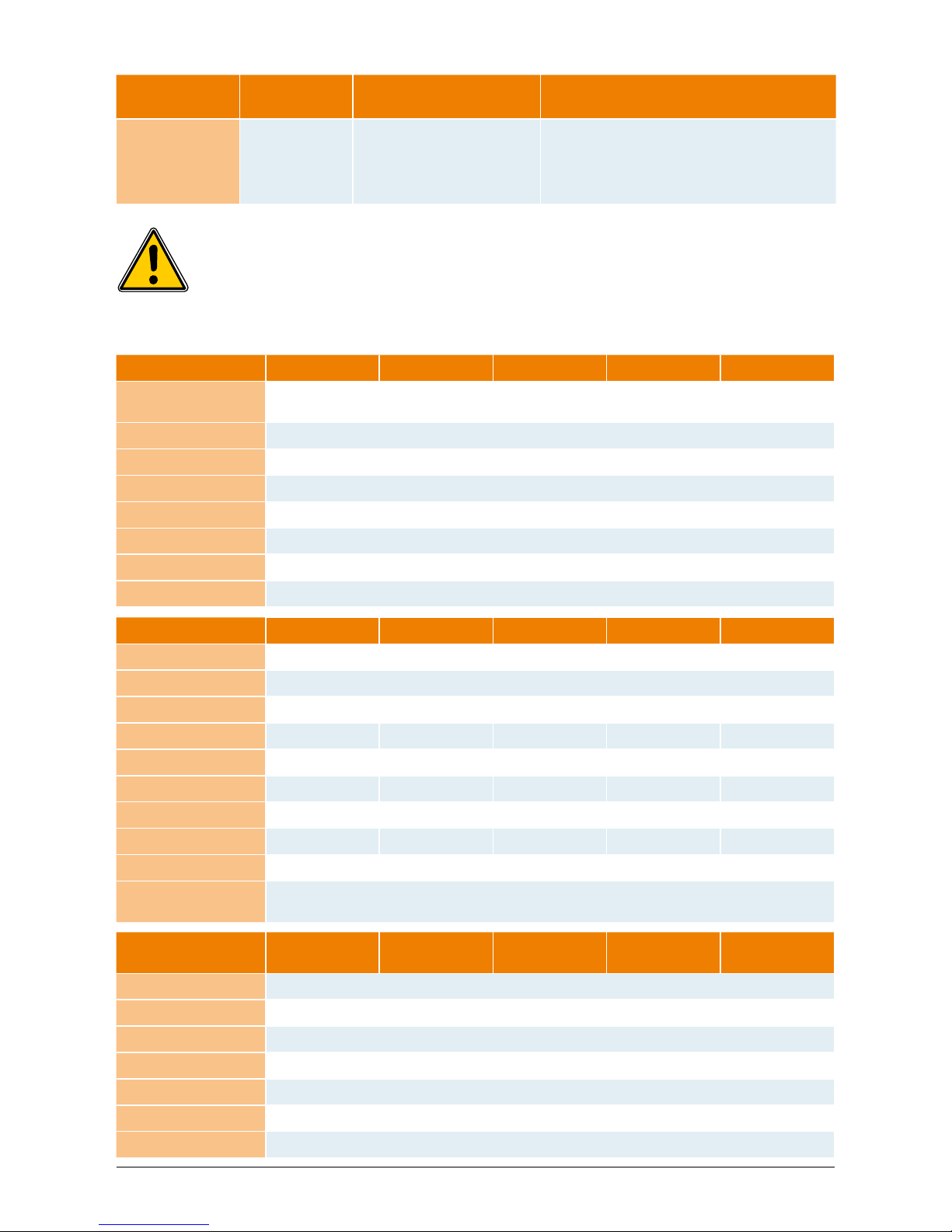
INPUT (DC) AUSTRALIA CHINA INDIA KOREA TAIWAN
Max. recommended
PV power
3100 W
Nominal power 2750 W
Voltage range 125 ... 540 V 125 ... 540 V 125 ... 540 V 125 ... 500 V 125 ... 540 V
MPP range 150 ... 450 V
Full power MPP range 150 ... 450 V
Nominal current 9.8 A
Max. current 18.0 A
Stand-by power < 0.2 W
OUTPUT (AC) AUSTRALIA CHINA INDIA KOREA TAIWAN
Max. power
1), 2)
2640 W
Nominal power
2)
2500 W
Nominal voltage 230 V 220 V 230 V 220 V 220 V
Voltage range 210.0 ... 264.0 V 187.0 ... 242.0 V 184.0 ... 264.5 V 193.6 ... 242.0 193.6 ... 253.0 V
Nominal current 10.9 A 11.4 A 10.9 A 11.4 A 11.4 A
Max. current 11.9 A 12.9 A 11.9 A 12.9 A 12.9 A
Nominal frequency 50 Hz 50 Hz 50 Hz 60 Hz 60 Hz
Frequency range 48.0 ... 52.0 Hz 49.5 ... 50.5 Hz 47.3 ... 52.7 Hz 59.3 ... 60.5 Hz 58.0 ... 61.0 Hz
Power factor (cos φ) > 0.99 @ nominal power
Total harmonic
distortion (THD)
< 3 % @ nominal power
GENERAL
SPECIFICATION
AUSTRALIA CHINA INDIA KOREA TAIWAN
Model name SOLIVIA 2.5 AP G3
Max. efficiency 96.0 %
Efficiency EU 94.8 %
Operating temperature -25 ... +70°C
Storage temperature -25 ... +80°C
Humidity 0 ... 98 %
Max. operating altitude 2000 m (above sea level)
Page 31

ENGLISH
29Operation and installation manual SOLIVIA 2.5 AP G3
MECHANICAL
DESIGN
AUSTRALIA CHINA INDIA KOREA TAIWAN
Size (L x W x D) 410 x 410 x 180 mm
Weight 21.5 kg
Cooling Free convection
AC connector Wieland RST25i3S
DC connector pairs 4 Multi-Contact MC4
Communication
interfaces
2 Harting RJ45 / RS485
Display LCD; 3 LEDs
STANDARDS /
DIRECTIVES
AUSTRALIA CHINA INDIA KOREA TAIWAN
Protection degree IP65
Safety class I
Overload behavior Current limitation; power limitation
Safety
AS/NZS 60950;
AS/NZS 3100;
AS 4777.2; AS
4777.3
CGC/
GF001:2009
IEC 62103:2003,
EN 50178:1997,
IEC 621091:2007, IEC
62109-2:2005
PV 501
IEC 62103:2003,
EN 50178:1997,
IEC 621091:2007, IEC
62109-2:2005
Anti-islanding
protection
AS 4777.2; AS
4777.3;
IEC 60255.5
Yes VDE 0126-1-1
PV 501; KS C
8540
Yes
EMC
AS 4777.1; AS
4777.2;
AS 4777.3; EN
61000-6-2; IEC /
EN 61000-6-3
GB /T 17626; GB
17799
IEC / EN 610006-2;
IEC / EN 610006-3
IEC 60725;
KS C IEC 610004-5; KS C IEC
61000-6-1;
KS C IEC 610006-2; KS C IEC
61000-6-3; KS C
IEC 61000-6-4
IEC / EN 610006-2;
IEC / EN 610006-3
1) The maximum AC power value indicates the power an inverter might be able to deliver. However, such a maximum
AC power may not necessarily be achieved.
2) In certain states in Australia, power limitation is required. With power limitation, the output (AC) power of SOLIVIA 2.5
AP G3 will be as followed :
Max power: 2490 W
Nominal power: 2350 W
Page 32

30 Operation and installation manual SOLIVIA 2.5 AP G3
10 Appendix
10.1 Connection examples
House connection box
House connection line
Low-voltage network ~ 400 / 220 V
Low-voltage network ~ 400 / 230 V
VNB
Customer
Owner boundary
Z
(1)
Z
(2)
Measurement unit
(1) Meter for power consumption
(2) Meter for power feed-in
with back stop in each case
Remark: A meter can also be employed
which registers both energy directions separately
=
~
~ 400 / 220 V
~ 400 / 230 V
Consumer
equipment of
the customer
Photovoltaic
generator with
power inverter
max. 4.6 kVA
Switching equipment
Electric circuit distributor
Anti-islanding protection with voltage and frequency
monitoring, as well as network impedance measurement
Short-circuit protection
Overload protection
Individual in-plant generation system in parallel operation without isolated
operation possibility, single-phase feed with anti-islanding protection.
Page 33

ENGLISH
31Operation and installation manual SOLIVIA 2.5 AP G3
House connection box
House connection line
VNB
Customer
Owner boundary
Z
(1)
Z
(2)
Measurement unit
(1) Meter for power consumption
(2) Meter for power feed-in
with back stop in each case
Remark: A meter can also be
employed which registers both energy
directions separately.
(3) Meter for power take-off of the
customer system
=
~
Consumer equipment
of the customer
Photovoltaic
generator with
power inverter
max. 4.6 kVA
Switching equipment
Electric circuit distributor
Anti-islanding protection with voltage and
frequency monitoring, as well as network
impedance measurement
Short-circuit protection
Overload protection
Individual in-plant generation system in parallel operation without isolated
operation possibility, single-phase feed with anti-islanding protection, separate feed.
Z
(3)
Low-voltage network ~ 400 / 220 V
Low-voltage network ~ 400 / 230 V
~ 400 / 220 V
~ 400 / 230 V
Page 34

32 Operation and installation manual SOLIVIA 2.5 AP G3
10.2 Overview of connection diagrams
+
-
DC terminal strip
DC disconnector
-
~
3 3
Z
Meter for
power feed-in
3
Z
3
3
3
Meter for
power
consumption
House
connection
box
Selective
main line
circuit breaker
House
connection
line
Consumer
equipment
Automatic
circuit breaker
type B 25 A
+
-
PV generator
PV generator
+
-
Solivia 2.5
DC disconnector
-
~
Automatic circuit
breaker
type B 25 A
PV generator
DC disconnector
-
~
Automatic
circuit breaker
type B 25 A
PV generator
kWh
kWh
Customer
Meter for
power feed-in
Meter for
power
consumption
Solivia 2.5 Solivia 2.5
Page 35

ENGLISH
33Operation and installation manual SOLIVIA 2.5 AP G3
DC disconnector
-
~
1
2
3
PV generator
-
~
-
~
L1 N PE
L2 N PE
L3 N PE
Fuse
L1
N
n
...
PE
L2
L3
Solivia 2.5
Page 36

34 Operation and installation manual SOLIVIA 2.5 AP G3
11 Glossary
AC
Abbreviation for „Alternating Current“.
Anti-islanding protection
This is a unit for grid monitoring with assigned switching elements (anti-islanding protection) and is
an automatic isolation point for small power generation systems (to 30 kWp).
CE
With the CE identication code, the manufacturer conrms the conformity of the product with the
valid EC Guideline and compliance with the signicant requirements stipulated therein.
DC
Abbreviation for „Direct Current“.
EMC
The Electro-Magnetic Compatibility (EMC) concerns the technical and legal basics of the mutual
inuencing of electrical devices through electromagnetic elds caused by them in electrical engineering.
Initialization
Under initialization (cf. English to initialize) is understood the part of the loading process of a program, in which the storage space required for the execution (e.g. variable, code, buffers ...) for the
program is reserved and is lled with initial values.
Local utility company
By local utility company is meant a company which generates electrical energy and distributes it
over the public grid.
MPP
The Maximum Power Point is the point of the current-voltage diagram of a PV cell at which the
largest power can be tapped off, i.e. the point at which the product of current and voltage has its
maximum value.
Nominal power
Nominal power is the maximum permissible continuous power output indicated by the manufacturer
for a device or a system. Usually the device is also optimized so that the efciency is at its maximum
in case of operation with nominal power.
Nominal current
Nominal current is the absorbed current in case of electrical devices if the device is supplied with
the nominal voltage and yields its nominal power.
PE
In electric systems and cables a protective earth conductor is frequently employed. This is also
called grounding wire, protective grounding device, soil, grounding or PE (English „protective
earth“).
Photovoltaics (abbr.: PV)
The conversion of PV energy into electrical energy.
The name is composed of the component parts: Photos - the Greek word for light - and Volta - after
Alessandro Volta, a pioneer in electrical research.
Page 37

ENGLISH
35Operation and installation manual SOLIVIA 2.5 AP G3
Potential isolation
No conductive connection between two component parts.
Power dissipation
Power dissipation is designated as the difference between absorbed power and power of a device
or process yielded. Power dissipation is released mainly as heat.
PV cell
PV cells are large-surface photodiodes which convert light energy (generally sunlight) into electrical
energy. This comes about by utilization of the photoelectric effect (photovoltaics).
PV generator
System comprising a number of PV modules.
PV module
Part of a PV generator; converts PV energy into electrical energy.
RJ45
Abbreviation for standardized eight-pole electrical connector connection. RJ stands for Registered
Jack (standardized socket).
RS485 (EIA485)
Differential voltage interface on which the genuine signal is transmitted on one core and the negated (or negative) signal on the other core.
Separate grid system
Energy supply equipment which is completely independent of an interconnected grid.
Solar inverter
is an electrical device which converts DC direct voltage into AC voltage and/or direct current into
alternating current.
String
Designates a group of electrical PV modules switched in series.
String solar inverter (solar inverter concept)
The PV generator is divided up into individual strings which feed into the grid over their own string
solar inverters in each case. In this way, the installation is considerably facilitated and the gain decrease, which can arise from the installation or from different shading conditions of the PV modules,
is considerably reduced.
TAB (2000)
The TAB 2000 are the technical regulations governing connection to the low-voltage grid operated
by distribution system operators in Germany. These Technischen Anschlussbestimmungen or TAB
for short have been in force since the year 2000. They dene the requirements imposed by DSOs
on the electrical systems operated by the end customers of utility companies.
Page 38

36 Operation and installation manual SOLIVIA 2.5 AP G3
Page 39

한국어
37
사용 및 설치 설명서SOLIVIA 2.5 AP G3
메뉴얼은 변경될 수 있습니다.
최근 업데이트 된 정보는 www.solar-inverter.com 를 참조하십시오.
© 저작권 – Delta Energy Systems (Germany) GmbH - 모든 권리 보유.
이 설명서는 최종 사용자가 사용할 수 있도록 장비와 함께 제공됩니다.
이 설명서에 나온 기술적인 설명과 그림은 기밀 정보로 취급해야 하며 어떤 부분도 Delta Energy Systems 기술자의 사전 서면
동의를 받지 않고 복제할 수 없습니다. 최종 사용자는 장비의 올바른 사용과 엄격하게 관련되지 않은 용도로 이 설명서에 담긴 정
보를 유출하거나 이 설명서를 사용할 수 없습니다.
모든 정보와 규격은 별도의 통지 없이 변경될 수 있습니다.
Page 40

38
사용 및 설치 설명서SOLIVIA 2.5 AP G3
Page 41

한국어
39
사용 및 설치 설명서SOLIVIA 2.5 AP G3
목차
1 제공 품목 40
2 일반 경고/안전 지침 40
3 소개 41
4 시스템 41
4.1 데이터 평가와 통신 41
4.2 태양광 인버터의 기술적 구조 42
4.3 장비 개요 43
5 설치 44
6 장비 설치 44
6.1 설치 위치 44
6.2 최소 요구 조건 44
6.3 유지 관리 45
6.4 설치 45
6.5 주위 온도 46
6.6 그리드 연결 46
6.7 태양광 모듈 연결 46
6.7.1 태양광 전압 대비 출력 전력 48
6.7.2 Output power over AC voltage 48
6.7.3 효율 49
6.8 인터페이스 연결 RS485(EIA485) 49
6.9 전기 연결 및 시동 51
6.10 구성/설정 52
6.11 LED 작동 및 문제 표시 53
7 작동 개념 54
7.1 디스플레이 54
7.2 디스플레이 탐색 54
7.3 메인 메뉴 54
7.3.1 하위 메뉴 N (현재) 56
7.3.2 하위 메뉴 D (일) 57
7.3.3 하위 메뉴 W (주) 58
7.3.4 하위 메뉴 M (월) 58
7.3.5 하위 메뉴 Y (연) 58
7.3.6 하위 메뉴 T (총합) 59
7.3.7 하위 메뉴 S (설정) 60
7.3.7.1 하위 메뉴 S: Solar ISO / GND 61
7.3.7.2 하위 메뉴 S: Country settings 61
7.3.7.3 하위 메뉴 S: Firmware 62
8 진단 및 데이터 평가 62
8.1 오작동 교정 62
8.2 디스플레이 메시지 63
9 기술 데이터 64
10 부록 66
10.1 연결 예 66
10.2 연결 도면 개요 68
11 용어집 70
12 연락처 140
Page 42

40
사용 및 설치 설명서SOLIVIA 2.5 AP G3
1 제공 품목
• 태양광 인버터 SOLIVIA 2.5 AP G3
• 부착판
• 사용 및 설치 설명서
• AC 커넥터
2 일반 경고/안전 지침
태양광 인버터 SOLIVIA 2.5 AP G3을 구입해 주셔서 감사합니다.
이 설명서에는 제품을 이해하는 데 도움이 되는 내용이 나와 있습니다.
안전 규정(9절 참조)과 현지 전력 회사를 위한 기술적 연결 조건을 준수하십시오. 사용 수명 및 내
구성, 신뢰성을 유지하려면 제품을 주의하여 사용하시기 바랍니다. 제품에서 최대 수율을 얻으려면
반드시 이러한 조건을 충족시켜야 합니다.
다음과 같은 안전 수칙을 따르십시오.
• 전기 장치가 작동 중일 때 특정 부품에 위험한 전압이 있을 수 있습니다.
• 부적절하게 취급하면 작업자가 다치거나 물품이 파손될 수 있습니다!
• 설치 규정을 준수하십시오.
• 설치와 시동 작업은 반드시 자격을 갖춘 전기 기술자가 실시해야 합니다.
• 장치에 대한 수리 작업은 반드시 제조 업체의 서비스 직원이 실시해야 합니다.
• 사용 및 설치 설명서의 모든 내용을 준수하십시오!
• 작업을 시작하기 전에 그리드와 태양광 모듈에서 장치를 분리하십시오.
• 장치 표면은 온도가 매우 높아 뜨거울 수 있습니다.
• 충분히 식혀야 합니다.
• 태양광 인버터가 무겁기 때문에(무게 > 18kg) 최소한 두 명이 들어야 합니다.
• 장치에 높은 누출 전류가 있음을 기억하십시오. 작업을 시작하기 전에 반드시 보호도체를 연결
해야 합니다.
감전 위험을 피하기 위해 태양광 인버터를 열지 마십시오. 인버터에는 사
용자가 수리할 수 있는 부품이 없습니다. 커버를 열면 보증을 받을 수 없
습니다.
모든 전원에서 분리한 후에도 5분 동안 위험 전압이 남아있습니다.
Page 43

한국어
41
사용 및 설치 설명서SOLIVIA 2.5 AP G3
3 소개
이 제품은 태양광 시스템을 그리드에 연결하기 위한 태양광 인버터입니다. 이 태양광 인버터는 첨
단 하우징 설계와 최신 고주파 기술로 최고 수준의 효율을 달성합니다.
이 인버터에는 단독 운전 방지 장치와 같은 모니터링 장치가 포함되어 있습니다. 단독 운전 방지
장치(시설 내의 발전 시스템에 대한 자동 분리점) 기능은 모든 요구되는 규격을 준수합니다(12절
참조).
또한 실내와 실외(IP65 등급)에서 사용할 수 있습니다.
다음의 기술 설명에는 설치 기술자와 사용자가 태양광 인버터를 설치, 시동, 취급하는 데 필요한 정
확한 기능에 대한 설명이 나옵니다.
4 시스템
태양광 인버터는 태양광 전지에서 발생하는 직류를 교류로 변환합니다. 이는 자체 생산된 태양광
에너지를 공공 그리드에 공급할 수 있도록 합니다.
효율적인 MPP 트래킹이 있어 구름이 낀 날씨에서도 태양광 플랜트의 최대 용량을 활용할 수 있
습니다.
스트링 방식이란 태양광 모듈이 항상 직렬로 연결되며(한 개의 스트링에서) 또한/혹은 같은 전압
의 스트링이 태양광 인버터에 병렬로 연결되어 태양광 시스템의 케이블 연결량을 크게 줄일 수 있
음을 의미합니다.
모듈이 스트링에 연결되기 때문에 태양광 시스템이 태양광 인버터의 입력 전압 범위에 완벽하게
일치할 수 있습니다.
4.1 데이터 평가와 통신
일체형 데이터 디스플레이, 처리, 통신 장치로 태양광 인버터를 쉽게 사용할 수 있습니다. 장치 디스
플레이에서 작동 상태를 모니터링하고 고장 신호를 불러올 수 있습니다. 데이터 인터페이스를 사용
해 데이터를 다운로드하여 PC에서 평가할 수 있고 작동 데이터를 연속적으로 기록할 수 있습니다.
이러한 기능을 이용하는 가장 좋은 방법은 제공되는 부속품을 이용하는 것입니다. 이러한 부속품을
이용하면 종합적이고 빈틈 없이 태양광 인버터를 모니터링할 수 있습니다.
태양광 작동 중에만 일체형 인터페이스와 디스플레이에서 데이터를 읽을 수 있습니다.
Page 44

42
사용 및 설치 설명서SOLIVIA 2.5 AP G3
4.2 태양광 인버터의 기술적 구조
일체형 고주파 변압기가 달린 DC/AC 컨버터를 통해 태양광 인버터를 그리드에서 전기적으로 분리
합니다. 여러 가지 태양광 조도와 온도에 따라 태양광 모듈의 최대 전력 출력 또한 얻을 수 있도록
태양광 전압을 조절합니다(MPP 트래킹).
태양광 인버터의 MPP 범위는 150V에서 450V까지입니다. 따라서 여러 제조 회사의 태양광 모듈
을 쉽게 사용할 수 있습니다. 최대 열린 회로 전압이 540VDC (대한민국은 500 V) 가 절대 넘지 않
도록 예방 조치를 취해야 합니다. 최대 열린 회로 전압은 최저 예상 온도에서 발생합니다. 이러한
온도 의존성에 대한 자세한 내용을 태양광 모듈의 데이터 시트에서 찾아볼 수 있습니다. 장치의 전
력 소비량은 최소로 유지됩니다.
고품질 알루미늄 케이싱은 IP65 보호 등급(워터젯과 먼지로부터 보호)으로 제작되어 있고 풍화에
잘 견디도록 표면 처리되어 있습니다. 인버터가 -25°C에서 +70°C까지 주위 온도에서 작동할 수
있도록 냉각 기능이 설계되어 있습니다.
이러한 냉각 기능으로 전압 변환을 통해 발생하는 전력 소실을 제거합니다. 내부 온도 제어기가
태양광 인버터 내부의 과열을 방지합니다. 주위 온도가 높은 경우 최대 전송 전력이 제한됩니다.
마이크로 컨트롤러가 태양광 인버터를 제어합니다. 이 마이크로 컨트롤러는 또한 인터페이스 통신
을 실행하고 디스플레이의 값과 메시지를 모니터링합니다.
두 개의 독립적인 중복 구성 마이크로 컨트롤러가 그리드 모니터링을 제어하며 이것은 현지 전력
회사의 전력 공급 지침에 부합됩니다. 이렇게 하면 태양광 인버터를 시설 내의 전기 그리드에 설
치할 수 있습니다.
그리드를 태양광 모듈에서 전기적으로 분리하여 작업자 보호 요건을 충족시킵니다. 그리드와 태양
광 모듈의 전기적 분리는 기본적인 절연과 같습니다. 그리드, 태양광 모듈과 접근 인터페이스(디
스플레이, RS485 인터페이스)를 서로 분리하여 최상의 작업자 보호를 보장합니다. 전자기 적합성
(EMC)과 안전성에 대한 관련 규격을 충족시킵니다.
태양광 인버터는 온그리드 작동 상태에서만 기능합니다. 인증 기관의 승인을 받은 자동 분리점이
회로 분리 또는 전원 공급 중단이 발생했을 때 안전한 차단을 보장하고 분리된 상태에서 작동하는
것을 방지합니다.
차단 장비를 사용해 공칭 전력이 4.6kVA 이하인 시설 내의 발전 시스템에 대한 자동 분리가 가능
하며 태양광 인버터를 통해 그리드에 단상 병렬식으로 전력을 공급할 수 있습니다.
Page 45

한국어
43
사용 및 설치 설명서SOLIVIA 2.5 AP G3
4.3 장비 개요
(1) 태양광 모듈 연결
(2) 그리드 연결
(3) 인터페이스 연결 RS485(EIA485)
(4) 상태 메시지 표시와 작동 키패드
(5) 작동 상태 표시 LED
(1)
(4)
(5)
(2)
(3)
Page 46

44
사용 및 설치 설명서SOLIVIA 2.5 AP G3
5 설치
설치와 시운전은 반드시 자격을 갖춘 전기 기술자가 실시해야 합니다.
해당 지역과 국가의 관련 안전 규정과 인터페이스에 대한 기술 조건(TAB 2000)을 준수해야 합
니다.
에너지 측정을 위해서는 그리드 전력 공급점과 태양광 인버터 사이에 계량기를 반드시 설치해야 합
니다(해당 지역과 국가의 모든 안전 규정을 준수).
일체형 단독 운전 방지 장치를 사용해 해당 지역과 국가의 모든 안전 규정에 따라 권장되는 구간
개폐기의 기능을 충족시킵니다.
자세한 내용은 9절을 참조하십시오.
주의: 이차 단락 전류 정격이 공공 전기 공급 시스템에 대한 전송 연결점에서 연결된 태양광 인버
터의 공칭 전류만큼 높아집니다.
6 장비 설치
6.1 설치 위치
• 불연성의 지지대 위에 장치를 설치하십시오.
• 진동이 있는 물체(가벼운 구조 벽 등)에 설치하지 마십시오.
• 실내와 보호 시설이 된 실외에 모두 설치할 수 있습니다.
• 주위 온도가 높아지면 태양광 시스템의 효율이 낮아질 수 있습니다.
• 소음이 발생할 수 있습니다(거주 지역에는 설치하지 말 것).
• LED와 디스플레이를 읽을 수 있는지 확인합니다(판독 각도와 설치 높이를 확인).
• 장치가 자외선에 강한 부품으로 구성되어 있기는 하지만 직사광선에 노출시키지 마십시오.
• 케이싱이 IP65 등급이고 오염 분류 III에 해당하는 인증을 받았으나, 장치가 매우 심하게 오염되
지 않도록 해야 합니다.
• 먼지가 많은 환경에서는 장치 기능이 저하될 수 있습니다.
6.2 최소 요구 조건
• 태양광 인버터 주변의 자유 대류가 방해받지 않아야 합니다.
• 공기가 올바로 순환해 열을 잘 발산하려면 측면으로 약 10cm, 위아래로 약 50cm 거리만큼의
공간이 필요합니다
• 공급 단자의 그리드 임피던스 요구 조건을 준수해야 합니다(케이블 길이, 케이블 단면적).
• 권장 설치 위치를 준수해야 합니다(수직).
• 사용하지 않은 DC 커넥터 와 인터페이스는 밀봉 마개로 공기가 통하지 않게 밀봉해서 전
체 시스템(인버터와 케이블)에서 IP65 보호 등급을 유지해야 합니다.
50 cm
10 cm
50 cm
10 cm
Wall
Wall
Page 47

한국어
45
사용 및 설치 설명서SOLIVIA 2.5 AP G3
319.5
150
320
200
6.5
12
Ø
12.5
90
38
12
410 ± 0.5
6.3 유지 관리
장치는 작동 중에 덮개를 씌우지 않은 상태로 유지해야 합니다. 태양광 인버터 케이싱이 오염되지
않도록 주기적으로 청소해야 합니다.
이 장치에는 사용자가 수리할 수 있는 부품이 없습니다. 어떤 경우에도 태양광 인버터를 열면 안
됩니다!
6.4 설치
태양광 인버터를 올바로 설치하려면 제공된 부착판을 사용해야 합니다. 벽에 설치할 때는 적합한
나사로 고정시켜야 합니다. 태양광 인버터를 쉽게 설치할 수 있도록 벽 받침대를 고정시킵니다. 그
다음 장치를 볼트로 단단히 고정시킵니다.
조립 방법
1. 적절한 나사(최대Ø 6mm)를 8개의 구멍 중 최소한 4개의 구멍에 채워 부착판을
설치하여 벽 받침대를 제자리에 고정시킵니다. 부착판을 구멍 위치를 표시하는 데
사용할 수 있습니다.
2. 태양광 인버터는 무게가 21.5kg이므로 최소한 두 명이 들어 운반해야 합니다.
3. 최소한 두 명이 태양광 인버터를 들어 부착판에 올려놓습니다.
4. 제공된 고정 너트와 와셔를 볼트에 조여 장치를 고정시킵니다.
5. 태양광 인버터가 단단히 밀봉되었는지 확인합니다.
부착판
잠금 나사
잠금 나사
Page 48

46
사용 및 설치 설명서SOLIVIA 2.5 AP G3
6.5 주위 온도
태양광 인버터는 -25°C에서 +70°C까지 주위 온도에서 작동할 수 있습니다.
장치를 환기가 잘 되는 시원하고 건조한 곳에 설치해야 합니다.
6.6 그리드 연결
그리드(AC 출력)를 Wieland RST25i3S AC 커넥터로 연결합니다. 커텍터의 나사형 단자 연결부에
올바른 연결 방법이 나와 있습니다. 태양광 인버터를 3선 라인(L, N, PE)으로 그리드에 연결해야 합
니다. AC 커넥터를 차단하거나 삽입하기 전에 연결한 AC 라인을 무전위 상태로 전환해야 합니다.
Wieland AC 커넥터에 연결할 때는 잘 휘는 라인과 단면적이 최소 2.5 mm², 최대 4.0 mm²인 전선
을 사용해야 합니다.
자동 회로 차단기를 모든 장치의 라인 L 업스트림에 설치해야 합니다. 공칭 전류는 25A이고 트리
핑 특성 유형 B 또는 C 이어야 합니다 (정확한 트리핑 특성 타입 사용을 위해 해당 지역 또는 국가
의 설치요구 사항 및 규정을 참고 하시길 바랍니다). 또한 자동 회로 차단기의 퓨즈 장착 업스트림
을 선택할 때 주의해야 합니다.
태양광 인버터를 AC 커텍터의 PE 전선을 통해 접지해야 합니다. 이렇게 하려면 PE 전선을 지정
된 단자에 연결합니다. 여러 개의 인버터를 설치하고자 할 때에는 부록에 나온 그림과 같이 작업
합니다.
원하지 않는 온도 상승과 전력 손실의 위험이 있으므로 케이블 길이와 케이블 단면적에 주의해야
합니다.
AC 커넥터는 나사 드라이버로 풀 수 있는 클립 장치에 의해 의도하지 않은 차단으로부터 보호됩
니다.
6.7 태양광 모듈 연결
태양광 시스템을 연결하기 전에 Multi-Contact 커넥터에서 태양광 전압 극성이 올바른지 확인해
야 합니다.
태양광 모듈을 연결할 때는 Multi-Contact MC4 커넥터를 사용해야 합니다. 이때 DC 음극이 커넥
터 윗줄에 있고 DC 양극이 커넥터 아랫줄에 있습니다. 커넥터는 작업자가 우발적으로 잘못된 단자
에 꽂는 것을 막기 위해 부호화되어 있습니다.
항상 다음을 확인하십시오.
• 태양광 인버터 연결 단자에 어떠한 사람도 접촉할 위험이 없어야 합니다. 이러한 단자에 위험 전
압이 있을 수 있기 때문입니다.
• 어떤 경우에도 태양광 모듈은 부하 상태의 태양광 인버터와 차단되지 않아야 합니다. 차단이 필요
한 경우 먼저 그리드를 꺼서 태양광 인버터가 더 이상 전력을 흡수하지 못하게 해야 합니다. 그 다
음 업스트림 DC 디스커넥터를 엽니다.
태양광 인버터의 최대 입력 전압은 540V (대한민국은 500 V) 입니다. 개별 Multi-Contact MC4
커넥터의 최대 전류 부하는 18A입니다.
태양광 인버터에는 DC측에 절연과 접지 모니터링 장치가 있습니다. Setup(설정) 메뉴 “S -> Solar
ISO / GND”에서 옵션을 구성할 수 있습니다(7.3.7.1절 참조).
Page 49

한국어
47
사용 및 설치 설명서SOLIVIA 2.5 AP G3
절연 모니터링에는 다음과 같이 두 가지 모드가 있습니다.
• ISO-ON-Error(절연에 문제가 발생하면 태양광 인버터가 그리드에서 차단)
• ISO-ON-Warning(태양광 인버터가 문제를 표시하지만 그리드에서 차단되지는 않음)
Delta의 태양광 인버터는 ISO-ON-Warning 모드로 설정되어 출고됩니다.
접지 모니터링에는 다음과 같이 두 가지 모드가 있습니다.
• PV+ grounding(태양광 발전기 양극의 접지 모니터링)
• PV- grounding(태양광 발전기 음극의 접지 모니터링)
이러한 모드에서는 태양광 인버터가 전력 공급 작동 상태로 유지되고 문제가 발생 했을때 그리드에
서 차단되지 않습니다. 디스플레이에 오류 메시지 “PV+ grounding fault” 또는 “PV- grounding
fault”가 나타납니다.
모듈 제조 회사가 규정한 요구 조건을 충족시키기 위해 태양광 시스템의 양극이나 음극을 연결해
야 할 경우 다음과 같이 할 수 있습니다. 인버터와 가까운 곳에서 접지 연속성을 실행해야 합니다.
Delta의 접지 키트 “Grounding Set A Solar”(EOE99000275)를 사용하는 것이 좋습니다. 접지 연
결을 모니터링하고 Setup(설정) 메뉴에서 구성할 수 있습니다(위 참조).
또는 다음과 같이 절연 및 접지 모니터링을 끌 수 있습니다.
• ISO / GND OFF.
케이블
커플러
극성
전선 크기
2.5 MM
2
(AWG 14)
전선 크기
4.0 MM2 - 6.0
MM² (AWG 12-10)
음 케이블
커플러
양 케이블
커플러
MULTICONTACT
주문 번호
플러스
커플러
• •
32.0010P0001-UR
32.0012P0001-UR
마이너스
커플러
• •
32.0011P0001-UR
32.0013P0001-UR
플러스
커플러
• •
32.0014P0001-UR
32.0016P0001-UR
마이너스
커플러
• •
32.0015P0001-UR
32.0017P0001-UR
DC 케이블을 인버터에 연결하기 위해 필요한 케이블 커플러 유형.
Page 50

48
사용 및 설치 설명서SOLIVIA 2.5 AP G3
6.7.1 태양광 전압 대비 출력 전력
150 VDC
200 VDC 250 VDC
300 VDC
350 VDC 400 VDC 450 VDC
W
W
W
6.7.2 Output power over AC voltage
W
W
W
210 VAC 230 VAC 250 VAC
270 VAC
Page 51

한국어
49
사용 및 설치 설명서SOLIVIA 2.5 AP G3
6.8 인터페이스 연결 RS485(EIA485)
사용하지 않는 인터페이스는 항상 닫아두어야 합니다. 인터페이스를 사용하는 경우 인터페이스
커넥터에 맞는 해당부품을 사용해야 합니다.
연결 커넥터 공급 업체 HARTING Deutschland GmbH & Co. KG (P.O. 2451, 32381 Minden;
Germany; www.harting.com).
주문 지정: 09 45 145 1510, Cable Manager Blue IP67 Push-Pull Data Plug
09 45 145 1500, Cable Manager White IP67 Push-Pull Data Plug
-
~
-
~
-
~
-
~
220V/230V
하우스 연결 라인
RS485(EIA485) – 연결
데이터 기록기
RS485 (EIA485)
종단 저항기
6.7.3 효율
태양광 인버터의 최대 효율은 >250V 입력 전압에서 얻어집니다.
84 %
86 %
88 %
90 %
92 %
94 %
96 %
0 W
400 W
800 W
1200 W
1600 W
2000 W
2400 W
2500 W @ 150 V
2500 W @ 250 V
2500 W @ 350 V
2500 W @ 450 V
Page 52

50
사용 및 설치 설명서SOLIVIA 2.5 AP G3
8
1
핀
1 소유
2 소유
3 소유
4 접지 (RS485)
5 소유
6 RX_B (RS485)
7 TX_A (RS485)
8 소유
평면도
커넥터 핀 지정 RS485(EIA485)
+5V
사용하지 않음
사용하지 않음
0R
0R
TX_A
RX_B
접지
Pin 7
Pin 6
100 ... 150
Ohm, 0,25W
여러 개의 장치를 직렬로 연결하고 데이터 라인의 전체 길이가 2m 이상이라면
RS485 (EIA485) 인터페이스 종단을 위해 다음과 같은 옵션을 사용할 수 있습니다.
Page 53

한국어
51
사용 및 설치 설명서SOLIVIA 2.5 AP G3
6.9 전기 연결 및 시동
태양광 인버터의 전기 연결은 케이싱에 부착된 커넥터 접점을 사용해 실시합니다. 어떤 경우에도
장치를 열면 안 됩니다!
전력
제어기
단독 운전
방지 장치
통신
작동 및 시스템 제어
MPP
트래커
-
-
부스터
-
-
분리
DC 버스
~
태양광 인버터
DC
DC
DC
DC
스트링
A
AC
공공
그리드
스트링
B
스트링
C
스트링
D
사용 및 설치 설명서SOLIVIA 2.5 AP G3
Page 54

52
사용 및 설치 설명서SOLIVIA 2.5 AP G3
장치를 전기적으로 연결하려면 다음과 같은 절차를 따라야 합니다.
1. DC 연결:먼저 태양광 모듈 스트링을 DC 디스커넥터(별도 구매)에 연결합니다.
2. DC 디스커넥터를 태양광 인버터에 연결합니다(극성 확인).
3. AC 연결:Wieland AC 커넥터를 AC 출력 케이블에 설치한 후 AC 커넥터를 태양광 인버터에
장착합니다. 슬리브 너트가 올바로 고정되었고 조여졌는지 확인하십시오.
4. 전원을 켜기 전에 마지막으로 모든 전선과 연결부를 점검합니다.
5. DC 디스커넥터를 닫습니다.
6. AC 출력측의 회로 차단기를 닫습니다.
7. 태양광 전압이 충분하면(UPV > 150V) 장치가 시동 모드에 들어갑니다.
8. 새 설비인 경우 하위 메뉴 S(설정)에서 시간과 날짜를 설정해야 합니다(7.3.7절 참조).
사용하지 않는 커넥터와 인터페이스는 모두 제공된 밀봉 마개로 밀봉해야 합니다.
6.10 구성/설정
태양광 인터페이스가 Delta 공장에서 출고될 때의 기본 디스플레이 언어는 영어입니다.
올바른 DC 전압으로 연결하고 자체 검사를 실시한 후에 네트워크 ID를 지정하고 원하는 국가를
선택하라는 메시지가 나옵니다(7.3.7.2절 참조)(선택 가능 국가: 호주, 호주 PL
1)
,중국, 인도, 대한
민국, 대만)
선택 내용을 사용자가 나중에 확인해야 합니다. 일단 확인하고 나면 네트워크 ID와 국가 설정이
컨트롤러 메모리에 저장되고 태양광 인버터가 작동 준비 상태가 됩니다.
5분 내에 아무 것도 입력하지 않으면 디스플레이의 ENTER 키가 잠깁니다. ENTER 키를 잠금 해
제하려면 DC 전압을 껐다 켜야 합니다.
1) 호주 일부 지역에서는, 출력제한이 필요로 합니다.
• 이러한 출력제한으로, SOLIVIA 2.5 AP G3의 출력(AC)은 하기 와 같습니다:
최대 출력: 2490 W
정격 출력: 2350 W
• 전력제한 활성화를 하기 위해서는, 특정지역인 “Australia PL” 을 선택하여야 합니다 (설정된 값은 암호화 처
리로 보호가 되어 있습니다):
Select unit ID = [1] & press <ENTER> 키 입력
Select country = [Australia PL] & press <ENTER> 키 입력
<ENTER> 키 입력으로 Confi rm country selection 확인
• 하기 라벨은 인버터 제품박스에 동봉 되어 있으며 반드시 모델라벨 옆에 붙이셔야 합니다.
• 출력제한 활성화 여부를 확인하기 위해서는, menu S (Setup)에서 „위“ or „아래“ 버튼으로 다음 과 같은 메시
지를 확인하시길 바랍니다:
at maximal output power of: 2.49kW
For Australia PL
This product has been power limited
S -> Country Set
AU L
Down
Up
AUstralia Limitation
Page 55

한국어
53
사용 및 설치 설명서SOLIVIA 2.5 AP G3
국가 선택
네트워크 ID 올림 네트워크 ID 내림
아래로*
위로*
네트워크 ID 입력
ENTER *
ESC *
국가 선택
다음 국가 이전 국가
ENTER *
정상 모드
* 아무 키도 누르지 않으면(5분 내에) 시간 초과
위로*
아래로*
국가를 선택하고 확인하고 나면 아래와 같은 방법으로만 국가 설정을 변경할 수 있습니다.
1. ESC + 를 몇 초 동안 눌러서 키 정보를 불러옵니다.
2. 키 코드를 태양광 지원팀(support@solar-inverter.com)에 알려주고 PIN 코드를 받습니다(한
번만 사용 가능!).
3. PIN 코드를 입력하고 나서 ESC + 를 누릅니다.
4.그 다음 PIN 코드를 입력하고 2회 확인하라는 메시지가 나옵니다.
5.확인하고 나면 원하는 국가를 선택할 수 있습니다.
a
참고: 위의 과정은 중단 없이 실행해야 합니다. 그렇지 않으면 국가 선택 모드로 유지됩니다.
Operation (A)
Earth Fault (B)
Failure (C)
• LED (A), 녹색:”작동“ - 작동 상태를 나타냅
니다.
• LED (B), 빨간색:”접지 문제“ - 절연 저항 문
제 또는 DC측 태양광 접지(GND) 문제를 나타
냅니다.
• LED (C), 노란색:”고장“ - 내부 또는 외부의
기존 문제 또는 그리드 전력 공급 작동이 중단
되었는지 나타냅니다.
6.11 LED 작동 및 문제 표시
태양광 인버터의 작동 상태를 표시하는 3개의 LED가 다음과 같이 앞면에 달려 있습니다.
LED 상태 작동 상태 설명
녹색:<꺼짐>
빨간색:<꺼짐>
노란색:<꺼짐>
야간 차단
입력 전압(UPV)이 100V보다 낮습니다.
태양광 인버터가 전력을 그리드로 공급하지 않고 있습니다.
녹색:<켜짐>
빨간색:<켜짐>
노란색:<켜짐
시작.
입력 전압:
UPV:100V - 150V
(자체 검사 진행 중)
녹색:<깜빡임>
빨간색:<꺼짐>
노란색:<꺼짐>
입력 및 그리드 모니
터링
시동 상태를 검사하고 있습니다.
Page 56

54
사용 및 설치 설명서SOLIVIA 2.5 AP G3
7 작동 개념
7.1 디스플레이
장치의 디스플레이는 다양한 정보를 나타냅니다. ENTER 키를 사용해 장치를 조정하고 정보를 얻
습니다. 표시되는 데이터의 허용 오차는 최대 5%입니다.
ESC
(A) (B) (C) (D)
7.2 디스플레이 탐색
디스플레이 조명
자동 작동에서 ENTER 키를 누르면 디스플레이 조명이 켜집니다. 30초 내에 아무 키도 누르지 않
으면 디스플레이 조명이 자동으로 꺼집니다. 설정 메뉴로 연속 조명과 자동 조명을 선택할 수 있습
니다. ENTER 키를 누르면 디스플레이 조명이 다시 켜집니다.
키 (A), ESC: 메뉴 항목에서 메인 메뉴로 이동하
고 각 하위 메뉴를 끝낼 때 사용합니다.
키 (B)와 (C): 개별 메뉴 항목에서 이동하고 설
정 메뉴에서 조정할 때 사용합니다.
키 (D), ENTER: ENTER 키는 메뉴 단계를 변
경하고 설정 화면에서 입력 내용을 확인하는 데
사용합니다.
7.3 메인 메뉴
메인 메뉴는 다음과 같은 7개의 하위 메뉴 항목으로 구성됩니다.
• 메뉴 N(현재)
• 메뉴 D(일)
• 메뉴 W(주)
• 메뉴 M(월)
• 메뉴 Y(연)
• 메뉴 T(총합)
• 메뉴 S(설정)
메뉴 항목 조작:
선택기 키를 활성화해 메인 메뉴를 이동할 수 있습니다
.
ENTER 키를 눌러 하위 메뉴를 선택합니다. 메뉴를 다시 끝내려면 ESC 키를 활성화합니다.
LED 상태 작동 상태 설명
녹색:<켜짐>
빨간색:<꺼짐>
노란색:<꺼짐>
전력 공급 작동
정상 작동 상태:
UPV:150V - 450V
녹색:<꺼짐>
빨간색:<켜짐/꺼짐>
노란색:<켜짐/꺼짐>
장비 고장
내부 또는 외부 고장(전력 공급 중단)
디스플레이 메시지도 참조하십시오!
녹색:<꺼짐>
빨간색:<켜짐/꺼짐>
노란색:<켜짐>
일반 오류
상태
태양광 인버터가 그리드에 연결되지 않았습니다.
전력이 공급되지 않습니다.
디스플레이 메시지도 참조하십시오!
녹색:<켜짐/꺼짐>
빨간색:<켜짐/꺼짐>
노란색:<깜빡임>
경고 메시지
태양광 인버터를 계속 사용할 수 있습니다.
디스플레이 메시지도 참조하십시오!
Page 57

한국어
55
사용 및 설치 설명서SOLIVIA 2.5 AP G3
User menu
Menu N - Now (act data)
Menu D - Day statistic
Menu W - Week statistic
Menu M - Month statistic
Menu Y - Year statistic
Menu T - Total statistic
Menu S - Setup inverter
Down
Down
Down
Down
Down
Down
Up
Up
Up
Up
Up
Up
Down to 2
1
Up to 1
2
Submenu N - Now
Submenu D - Day
Submenu W - Week
Submenu M - Month
Submenu Y - Year
Submenu T - Total
Submenu S - Setup
ESC
ESC
ESC
ESC
ESC
ESC
ESC
ENTER
ENTER
ENTER
ENTER
ENTER
ENTER
ENTER
비고: 메인 메뉴에서 ESC를 누르면 해당
하위 메뉴의 첫 번째 입력 내용으로 건너뜁니다.
Page 58

56
사용 및 설치 설명서SOLIVIA 2.5 AP G3
7.3.1 하위 메뉴 N (현재)
이 메뉴 항목은 현재의 측정값을 표시합니다.
Main menu N - Now
actual data
N -> AC-Power Value (W)
N -> AC-Voltage Value (V)
N -> AC-Current Value (A)
N -> AC-Frequency
Value (Hz)
N -> PV-Voltage Value (V)
N -> PV-Current Value (A)
N -> Time (HH:MM:SS)
N -> Date
(WD.DD.MM.YYYY)
Down
Down
Down
Down
Down
Down
Down
Up
Up
Up
Up
Up
Up
Up
Down to 2
1
Up to 1
2
Submenu N - Now
ESC
ESC
ESC
ESC
ESC
ESC
ESC
ESC
ENTER
현재의 출력 전력을 표시합니다.
현재의 출력 전압을 표시합니다.
현재의 출력 전류를 표시합니다.
현재의 간선 주파수를 표시합니다.
현재의 태양광 전지 전압을 표시합니다.
현재의 태양광 전지 전류를 표시합니다.
현재의 시간을 표시합니다.
현재의 요일과 날짜를 표시합니다.
Page 59

한국어
57
사용 및 설치 설명서SOLIVIA 2.5 AP G3
7.3.2 하위 메뉴 D (일)
이 메뉴 항목은 그리드 전력 공급을 위한 일간 측정값을 표시합니다.
Main menu D - Day statistic
D -> Energy Value (Wh)
D -> AC-Revenue Value
(AUD / Won)
D -> AC-Power-Max
Value (W)
D -> AC-Volt-Max
Value (V)
D -> AC-Volt-Min
Value (V)
D -> AC-Curr-Max
Value (A)
D -> AC-Freq.-Max
Value (Hz)
D -> Runtime Value (Min)
Down
Down
Down
Down
Down
Down
Down
Up
Up
Up
Up
Up
Up
Up
Down to 2
1
Up to 1
2
Submenu D - Day
ESC
ESC
ESC
ESC
ESC
ESC
ESC
ESC
ENTER
D -> AC-Freq.-Min
Value (Hz)
ESC
Down
Up
일간 에너지 획득량을 표시합니다.
일간 수입을 표시합니다.
일간 최대 출력 전력을 표시합니다.
일단 최대 출력 전압을 표시합니다.
일간 최소 출력 전압을 표시합니다.
일간 최대 출력 전류를 표시합니다.
일간 최대 출력 주파수를 표시합니다.
일간 최소 출력 주파수를 표시합니다.
태양광 인버터의 일간 작동 시간을 표시합니다.
Page 60

58
사용 및 설치 설명서SOLIVIA 2.5 AP G3
7.3.3 하위 메뉴 W (주)
이 하위 메뉴는 현재 주의 평균값을 표시합니다.
Main menu W - Week statistic
W -> Energy Value (kWh)
W -> AC-Revenue
Value (AUD / Won)
W -> Runtime Value (h)
Down
Down
Up
Up
Down to 2
1
Up to 1
2
Submenu W - Week
ESC
ESC
ESC
ENTER
주간 에너지 획득량을 표시합니다.
주간 수입을 표시합니다.
태양광 인버터의 주간 작동 시간을 표시합니다.
7.3.4 하위 메뉴 M (월)
이 하위 메뉴는 현재 달의 평균값을 표시합니다.
Main menu M - Month statistic
M -> Energy Value (kWh)
M -> AC-Revenue
Value (AUD / Won)
M -> Runtime Value (h)
Down
Down
Up
Up
Down to 2
1
Up to 1
2
Submenu M - Month
ESC
ESC
ESC
ENTER
월간 에너지 획득량을 표시합니다.
월간 수입을 표시합니다.
태양광 인버터의 월간 작동 시간을 표시합니다.
7.3.5 하위 메뉴 Y (연)
이 하위 메뉴는 현재 연도의 평균값을 표시합니다.
Main menu Y - Year statistic
Y -> Energy Value (kWh)
Y -> AC-Revenue
Value (AUD / Won)
Y -> Runtime Value (h)
Down
Down
Up
Up
Down to 2
1
Up to 1
2
Submenu Y - Year
ESC
ESC
ESC
ENTER
연간 에너지 획득량을 표시합니다.
연간 수입을 표시합니다.
태양광 인버터의 연간 작동 시간을 표시합니다.
Page 61

한국어
59
사용 및 설치 설명서SOLIVIA 2.5 AP G3
7.3.6 하위 메뉴 T (총합)
이 메뉴 항목은 최초 사용 이래로 누적된 값과 최대/최소값을 보여줍니다.
Main menu T - Total statistic
T -> Energy Value (kWh)
T -> Revenue Value
(AUD / Won)
T -> PV-Vol. Max
Value (V)
T -> PV-Cur. Max
Value (A)
T -> PV-Pow. Max
Value (W)
T -> Isolation Max
Value (kOhm)
T -> Isolation Min
Value (kOhm)
T -> Runtime Value (Min)
Down
Down
Down
Down
Down
Down
Down
Up
Up
Up
Up
Up
Up
Down to 2
1
Up to 1
2
Submenu T - Total
ESC
ESC
ESC
ESC
ESC
ESC
ESC
ESC
ENTER
Up
에너지 획득량 총합을 표시합니다.
수익 총합을 표시합니다.
최대 태양광 전지전압을 표시합니다.
최대 태양광 전지전류를 표시합니다.
최대 태양광 전지전력을 표시합니다.
최대 절연 저항을 표시합니다.
최소 절연 저항을 표시합니다.
태양광 인버터의 작동 시간 총합을 표시합니다.
Page 62

60
사용 및 설치 설명서SOLIVIA 2.5 AP G3
7.3.7 하위 메뉴 S (설정)
이 메뉴 항목은 태양광 인버터의 기존 설정을 변경하는 데 사용합니다.
Main menu S - Setup
S -> LCD-Contrast
0 ... 9
S -> LCD-Backlight
Auto / On
S -> Menu-Mode
Now ... Setup
S -> Cash per kWh Value
(AUD / Won)
S -> ID-Number
001 ... 254
S -> Solar ISO / GND
S -> Baudrate
2400 ... 38400
Down
Down
Down
Down
Down
Down
Up
Up
Up
Up
Up
Down to 2
1
Up to 1
2
Submenu S - Setup
ESC
ESC
ESC
ESC
ESC
ESC
ESC
ENTER
Up
S -> Time (HH:MM:SS)
Down
ESC
Up
S -> Date
(WD.DD.MM.YYYY)
Down
ESC
Up
S -> Firmware
Down
ESC
Up
펌웨어를 조정합니다.
LCD 디스플레이의 밝기를 0부터9까지 조절합니다.
LCD 배경 조명을 조절합니다.
장치를 다시 시작할 때 시작 메뉴를 선택합니다.
전력 공급 금액을 kWh당 호주 달러/원 단위로 입력합니다.
태양광 인버터의 ID 번호를 입력합니다.
데이터 전송 속도를 2400-38400 보드 범위에서 조정합니다.
내장된 시계를 조정합니다.
현재의 요일과 날짜를 조정합니다.
ISO/GND를 설정합니다.
S -> Country settings
Name of country
ESC
Down
국가 매개 변수를 조정합니다.
Up
Page 63

한국어
61
사용 및 설치 설명서SOLIVIA 2.5 AP G3
7.3.7.1 하위 메뉴 S: Solar ISO / GND
하위 메뉴 S(설정)의 Solar ISO / GND 메뉴에 대한 보다 자세한 내용.
Submenu Setup
Solar ISO / GND
S -> Solar ISO / GND
ISO ON-Warning
S -> Solar ISO / GND
ISO ON-Failure
S -> Solar ISO / GND
ISO GND-OFF
S -> Solar ISO / GND
PV+ grounded
S -> Solar ISO / GND
PV- grounded
Down
Down
Down
Down
Up
Up
Up
Up
Down to 5
6
Up to 6
5
ESC
ESC
ESC
ESC
ESC
ENTER
Use old setting
ENTER
ENTER
ENTER
ENTER
ENTER
Use new value
7.3.7.2 하위 메뉴 S: Country settings
하위 메뉴 S(설정)의 국가 설정 메뉴에 대한 보다 자세한 내용.
Submenu Setup
Country settings
Name of country
S -> Country settings
Critical undervoltage
x(V) < x.xx(s)
S -> Country settings
Undervoltage
x(V) < x.xx(s)
S -> Country settings
Overvoltage
x(V) < xmin
S -> Country settings
Critical overvoltage
x(V) < x.xx(s)
S -> Country settings
Low frequency
xx.xx(Hz) < x.xx(s)
S -> Country settings
High frequency
x.xx(Hz) < x.xx(s)
S -> Country settings
Islanding
Active / Not active
Down
Down
Down
Down
Down
Down
Down
Up
Up
Up
Up
Up
Up
Up
Down to 5
6
Up to 6
5
ESC
ESC
ESC
ESC
ESC
ESC
ESC
ENTER
S -> Country settings
DC injection
x(mA) < x.xx(s)
ESC
Up
S -> Country settings
Sync time
x(s)
ESC
Down
Page 64

62
사용 및 설치 설명서SOLIVIA 2.5 AP G3
8 진단 및 데이터 평가
8.1 오작동 교정
태양광 인버터에는 자동 진단 시스템이 달려 있어 특정한 문제를 독립적으로 파악하고 디스플레
이에 표시합니다.
현장에서 문제 해결
원칙적으로 디스플레이에 오류 메시지가 나올 때마다 태양광 인버터를 다시 시작해서 초기화하는
것이 좋습니다.
장치를 초기화하는 방법은 다음과 같습니다.
1.태양광 인버터를 그리드에서 분리합니다(자동 회로 차단기 개방).
2.DC 디스커넥터를 끕니다.
3.대기: 약 1분
4.DC 디스커넥터를 다시 켭니다.
5.그리드로 전환합니다(자동 회로 차단기 닫기).
(현장에서 첫 번째 단계는 태양광 인버터가 탐지해낼 수 있고 트리핑을 발생시키는 잠재적 문제의
원인을 살펴보는 것입니다.)
디스플레이를 통해 다양한 주요 매개 변수를 살펴보고 잠재적 문제의 원인에 대한 결론을 이끌어
낼 수 있습니다.
N 메뉴에서 전류값
AC 전압 -> 현재의 출력 전압 표시값 -> 전압 제한값
AC 주파수 -> 현재의 그리드 주파수 표시값 -> 주파수 제한값
태양광 전압 -> 현재의 태양광 전지 전압 표시값 -> 전환 임계값
7.3.7.3 하위 메뉴 S: Firmware
하위 메뉴 S(설정)의 펌웨어 메뉴에 대한 보다 자세한 내용.
Submenu Setup
Firmware
S -> Firmware
AC-Ctrl maj.min.bug
Down
Down
Down
Up
Up
Up
Down to 4
3
Up to 3
4
ESC
ESC
ESC
ESC
ENTER
S -> Firmware
DC-Ctrl maj.min.bug
S -> Firmware
SC-Ctrl maj.min.bug
S -> Firmware
Display-Ctrl maj.min.bug
Page 65

한국어
63
사용 및 설치 설명서SOLIVIA 2.5 AP G3
8.2 디스플레이 메시지
LED 상태
디스플레이
메시지
원인 해결
녹색:<켜짐>
빨간색:<켜짐>
노란색:<켜짐>
- 디스플레이 통신의 문제
- 장치를 초기화해도 문제가 지속되면 서
비스 센터에 문의하십시오.
녹색:<꺼짐>
빨간색:<꺼짐>
노란색:<켜짐>
AC frequency failure
그리드 주파수가 지정
된 한도 범위를 초과하거
나 미달
- 디스플레이에서 N 메뉴의 그리드 주파수
를 점검합니다.
녹색:<꺼짐>
빨간색:<꺼짐>
노란색:<켜짐>
AC voltage
failure
그리드 전압이 지정된 한
도 범위를 초과하거나
미달
- 디스플레이에서 N 메뉴의 그리드 전압을
점검합니다.
- 전압이 없으면 그리드 자동 회로 차단기
를 점검합니다.
녹색:<꺼짐>
빨간색:<꺼짐>
노란색:<켜짐>
AC relay
failure
단독 운전 방지 장치 출력
릴레이 중 하나가 고장 또
는 결함
- 태양광 인버터에 결함이 있습니다.
- 장치를 반품하십시오.
녹색:<깜빡임>
빨간색:<꺼짐>
노란색:<꺼짐>
Calibration
ongoing
내부 설정 점검 입력 모드 전에 정상 기능
녹색:<꺼짐>
빨간색:<꺼짐>
노란색:<켜짐>
DC injection
failure
DC 구성품의 입력측 교류
가 너무 높음
- 장치를 초기화해도 문제가 계속 발생하
면 서비스 센터에 문의하십시오.
녹색:<꺼짐>
빨간색:<꺼짐>
노란색:<켜짐>
Error # 301
내부 통신 오류 또는 하드
웨어 고장
- 장치를 초기화해도 문제가 계속 발생하
면 서비스 센터에 문의하십시오.
녹색:<꺼짐>
빨간색:<꺼짐>
노란색:<켜짐>
Error # 302
온도가 떨어지면 장치가
작동을 멈추고 그리드 입
력 모드로 복귀합니다.
- 설치 장소를 점검합니다(직사 광선이 없
고 공기 순환이 잘 되는 곳).
녹색:<꺼짐>
빨간색:<켜짐>
노란색:<꺼짐>
Error # 506
Error # 508
시동(#508) 또는 작동
(#506) 중에 DC측에서 절
연 저항 문제가 발생
- 태양광 모듈의 DC측에서 절연 저항을 점
검합니다.
녹색:<켜짐>
빨간색:<켜짐>
노란색:<꺼짐>
Isolation
start-up
warning
Isolation running warning
시동 또는 작동 중에 DC측
에서 절연 저항 문제가 발생
- 태양광 모듈의 DC측에서 절연 저항을 점
검해야 합니다.
태양광 인버터가 여전히 전력을 공급합
니다!
녹색:<켜짐>
빨간색:<켜짐>
노란색:<꺼짐>
PV+ grounding fault
PV- grounding fault
GND에 대한 PV+(PV-)
연결이 차단되었거나
GND에 잘못된 극성이 연
결되었습니다.
- GND가 올바로 연결되었는지 점검하고
접지 경로에 있는 퓨즈를
점검합니다. 필요하다면 퓨즈를
교체합니다. 태양광 인버터가 전력 공급
상태를 유지합니다.
녹색:<꺼짐>
빨간색:<꺼짐>
노란색:<켜짐>
Revision
error
하드웨어/소프트웨어 버전
이 호환되지 않음
- 장치를 초기화해도 문제가 계속
발생하면 서비스 센터에
문의하십시오.
녹색:<켜짐>
빨간색:<켜짐>
노란색:<켜짐>
Self test
ongoing
시동 중에 태양광 인버
터 시작
첫 번째 태양광 인버터 시동:
- 정상 기능을 유지해야 하고 태양광 전
지 전압이
100V-150V이어야 합니다.
녹색:<깜빡임>
빨간색:<꺼짐>
노란색:<꺼짐>
PV power
too low
입력 전력이 부족함
- 일사율이 불충분합니다(새벽/해질녘).
- 디스플레이에서 N 메뉴의
태양광 전지 전압을 점검합니다.
녹색:<깜빡임>
빨간색:<꺼짐>
노란색:<꺼짐>
PV voltage
too low
태양광 발전기 전압이
100V-150V이어야 합
니다.
- 일사율이 불충분합니다.
- 디스플레이에서 N 메뉴의
태양광 전지 전압을 점검합니다.
녹색:<깜빡임>
빨간색:<꺼짐>
노란색:<꺼짐>
Synchronize
to AC
그리드 입력 모드에 대한
그리드 전압과 그리드 주
파수 점검
- 입력 모드 전에 정상 기능
Page 66

64
사용 및 설치 설명서SOLIVIA 2.5 AP G3
서비스 센터에 연락하기 전에 위에 나온 문제 해결 방법을 따르십시오!
9 기술 데이터
LED 상태
디스플레이
메시지
원인 해결
녹색:<켜짐>
빨간색:<꺼짐>
노란색:<깜빡임>
Varistor
warning
DC 입력측 내부 배리스터
에 결함 발생
- 이론적으로는 태양광 인버터를
계속 사용할 수 있지만 가능한 한
빨리 배리스터를 교환해야
합니다. 이를 위해 장치를 반품해야
합니다.
입력 (DC) 호주 중국 인도 대한민국 대만
최대 권장 태양광 전력 3100 W
공칭 전력 2750 W
전압 범위 125 ... 540 V 125 ... 540 V 125 ... 540 V 125 ... 500 V 125 ... 540 V
MPP 범위 150 ... 450 V
최대 출력 MPP 범위 150 ... 450 V
공칭 전류 9,8 A
최대 전류 18,0 A
대기 전력 < 0,2 W
출력 (AC) 호주 중국 인도 대한민국 대만
최대 전력
1), 2)
2640 W
공칭 전력
2)
2500 W
공칭 전압 230 V 220 V 230 V 220 V 220 V
전압 범위 210,0 ... 264,0 V 187,0 ... 242,0 V 184,0 ... 264,5 V 193,6 ... 242,0 V 193,6 ... 253,0 V
공칭 전류 10,9 A 11,4 A 10,9 A 11,4 A 11,4 A
최대 전류 11,9 A 12,9 A 11,9 A 12,9 A 12,9 A
공칭 주파수 50 Hz 50 Hz 50 Hz 60 Hz 60 Hz
주파수 범위 48,0 ... 52,0 Hz 49,5 ... 50,5 Hz 47,3 ... 52,7 Hz 59,3 ... 60,5 Hz 58,0 ... 61,0 Hz
역률 공칭 전력에서 > 0,99
총 고조파 왜곡률
(THD)
공칭 전력에서 < 3 %
일반 규격 호주 중국 인도 대한민국 대만
모델 이름 SOLIVIA 2.5 AP G3
최대 효율 96,0 %
효율 EU 94,8 %
작동 온도 -25°C에서 +70°C까지
보관 온도 -25°C에서 +80°C까지
습도 0%에서 98%까지
최고 해발고도 2000 m
Page 67

한국어
65
사용 및 설치 설명서SOLIVIA 2.5 AP G3
기계 설계 호주 중국 인도 대한민국 대만
크기(길이x폭x두께) 410 x 410 x 180 mm
무게 21,5 kg
냉각 자유 대류
AC 커넥터 Wieland RST25i3S
DC 커넥터 페어 4개의 Multi-Contact MC4
통신 인터페이스 2개의 Harting RJ45 / RS485
디스플레이 LCD: 3개의 LED
규격 / 지침 호주 중국 인도 대한민국 대만
보호 등급 IP65
안전 등급 I
과부하 대응 전류 제한, 전력 제한
안전
AS/NZS 60950;
AS/NZS 3100;
AS 4777.2;
AS 4777.3
CGC/GF001:2009
IEC 62103:2003,
EN 50178:1997,
IEC 621091:2007, IEC
62109-2:2005
PV 501
IEC 62103:2003,
EN 50178:1997,
IEC 621091:2007, IEC
62109-2:2005
단독 운전 방지 장치
AS 4777.2;
AS 4777.3;
IEC 60255.5
예 VDE 0126-1-1
PV 501; KS C
8540
예
EMC
AS 4777.1;
AS 4777.2;
AS 4777.3;
EN 61000-6-2;
IEC / EN 610006-3
GB /T 17626;
GB 17799
IEC / EN 610006-2;
IEC / EN 610006-3
IEC 60725;
KS C IEC 610004-5; KS C IEC
61000-6-1; KS C
IEC 61000-6-2;
KS C IEC 610006-3; KS C IEC
61000-6-4
IEC / EN 610006-2;
IEC / EN 610006-3
1) 최대출력용량 값은 인버터가 전달가능 한 용량이 표시됨. 그러나, 이와 같은 최대출력용량 값은 반드시 출력 될 필요
는 없음.
2) 호주 일부 지역에서는, 출력제한이 필요로 합니다. 이러한 출력제한으로, SOLIVIA 2.5 AP G3의 출력(AC)은 하기 와
같습니다:
최대 출력: 2490 W
정격 출력: 2350 W
Page 68

66
사용 및 설치 설명서SOLIVIA 2.5 AP G3
10 부록
10.1 연결 예
하우스 연결 상자
하우스 연결 라인
저전압 네트워크 ~ 400/220V
저전압 네트워크 ~ 400 / 230 V
VNB
고객
소유자 경계
Z
(1)
Z
(2)
측정 장치
(1) 전력 소비량 계량기
(2) 각 케이스마다 백스톱이 있는 공급 전력 계량기
비고:두 개의 에너지 방향을 별도로 등록하는
계량기를 사용할 수도 있습니다.
=
~
~ 400 / 220 V
~ 400 / 230 V
고객의 소비 장비
태양광 발전기,
전력 인버터 최대4.6kVA
개폐 장비
전기 회로 분배기
전압과 주파수 모니터링 기능과 네트워크
임피던스 측정 기능이 있는 단독 운전 방지 장치
단락 보호 장치
과부하 장치
시설 내의 병렬 작동식 개별 발전 시스템, 개별 작동의 가능성이 없음,
단상 전력 공급, 단독 운전 방지 장치.
Page 69

한국어
67
사용 및 설치 설명서SOLIVIA 2.5 AP G3
하우스 연결 상자
하우스 연결 라인
저전압 네트워크 ~ 400/220V
저전압 네트워크 ~ 400 / 230 V
VNB
고객
소유자 경계
Z
(1)
Z
(2)
측정 장치
(1) 전력 소비량 계량기
(2) 각 케이스마다 백스톱이 있는 공급 전력 계량기
(3) 고객 시스템의 전력 인출 계량기
비고:두 개의 에너지 방향을 별도로 등록하는
계량기를 사용할 수도 있습니다.
=
~
~ 400 / 220 V
~ 400 / 230 V
고객의 소비 장비
태양광 발전기,
전력 인버터 최대4.6kVA
개폐 장비
전기 회로 분배기
전압과 주파수 모니터링 기능과 네트워크
임피던스 측정 기능이 있는 단독 운전 방지 장치
단락 보호 장치
과부하 장치
시설 내의 병렬 작동식 개별 발전 시스템, 개별 작동의 가능성이 없음,
단상 전력 공급, 단독 운전 방지 장치, 별도 전력 공급.
Page 70

68
사용 및 설치 설명서SOLIVIA 2.5 AP G3
10.2 연결 도면 개요
+
-
DC 말단 단자
DC 디스커넥터
-
~
3 3
Z
공급 전력
계량기
3
Z
3
3
3
전력 소비량
계량기
하우스
연결 상자
선별적 간선
회로 차단기
하우스
연결 라인
소비 장비
자동 회로
차단기 유형 B
25 A
+
-
태양광 발전기
태양광 발전기
+
-
Solivia 2.5
DC 디스커넥터
-
~
자동 회로
차단기 유형 B
25 A
태양광 발전기
DC 디스커넥터
-
~
자동 회로
차단기 유형 B
25 A
태양광 발전기
kWh
kWh
고객
공급 전력
계량기
전력 소비량
계량기
Solivia 2.5 Solivia 2.5
Page 71

한국어
69
사용 및 설치 설명서SOLIVIA 2.5 AP G3
DC 디스커넥터
-
~
1
2
3
태양광 발전기
-
~
-
~
L1 N PE
L2 N PE
L3 N PE
L1
N
n
...
PE
L2
L3
Solivia 2.5
퓨즈
Page 72

70
사용 및 설치 설명서SOLIVIA 2.5 AP G3
11 용어집
AC
Alternating Current(교류)의 약어.
단독 운전 방지 장치
지정된 개폐 소자로 그리드를 모니터링(단독 운전 방지)하고 소규모 발전 시스템(30kWp 이하)에
대한 자동 분리점 역할을 합니다.
CE
CE 코드가 있으면 해당 제품이 관련 EC 지침을 준수하고 그에 따른 요구 조건을 충족시킴을 의
미합니다.
DC
Direct Current(직류)의 약어입니다.
EMC
전자기 적합성(Electro-Magnetic Compatibility)은 전기 공학에서 전자기장을 통해 상호 영향을
미칠 수 있는 전기 장치의 기술적, 법적 기본 문제에 관한 것입니다.
시작
시작은프로그램을 불러오는 과정의 일부이며 프로그램 실행(예: 변수, 코드, 버퍼...)을 위한 저장
장치 공간이보존되고 초기값으로 채워집니다.
현지 전력 회사
전기 에너지를 생산하고 공공 그리드를 통해 송전하는 회사를 의미합니다.
MPP
최대 전력점(Maximum Power Point)은 태양광 전지의 전류/전압 그림에서 최대 전력을 얻을 수
있는 점, 다시 말해서 전류와 전압이 최대값이 되는 점을 말합니다.
공칭 전력
공칭 전력이란 장치나 시스템에 대해 제조 업체가 지정하는 최대 허용 연속 전력 출력을 말합니다.
일반적으로 공칭 전력으로 작동할 때 효율이 최대가 되도록 장치를 최적화합니다.
공칭 전류
공칭 전류란 전기 장치에 공칭 전압이 공급되고 공칭 전력을 생산하는 경우 전기 장치의 흡수 전
류를 의미합니다.
PE
전기 시스템과 케이블에서 종종 보호 접지 전선을 사용합니다. 이러한 전선을 접지 전선, 보호 접지
장치, 대지, 접지, 보호 접지(PE)라고 부릅니다.
태양광(약어:PV)
태양 에너지를 전기 에너지로 변환.
영문 이름(Photovoltaics)은 다음과 같이 구성됩니다. Photos -빛을 의미하는 그리스어. Volta 전기 연구의 선구자인 Alessandro Volta의 이름에서 따옴.
전위 분리
두 구성품 사이에 전도성 연결이 없음.
전력 소실
전력 손실은 어떤 장치 혹은 과정상에서, 흡수된 전력과 생산된 전력간의 차이를 말합니다. 전력 소
실은 주로 열로 방출됩니다.
Page 73

한국어
71
사용 및 설치 설명서SOLIVIA 2.5 AP G3
태양광 전지
태양광 전지는 표면적이 큰 광다이오드로서 빛 에너지(일반적으로 햇빛)를 전기 에너지로 변환합
니다. 광전기(태양광 발전) 효과를 이용합니다.
태양광 발전기
수 많은 태양광 모듈로 구성된 시스템.
태양광 모듈
태양광 발전기의 일부분으로 태양광 에너지를 전기 에너지로 변환합니다.
RJ45
표준 8극 전기 커넥터 연결의 약어입니다. RJ는 Registered Jack(표준 소켓)의 약어입니다.
RS485(EIA485)
실제 신호는 한 코어로 전달되고 무효화(음성) 신호는 다른 코어로 전달되는 차등 전압 인터페이스.
독립 그리드 시스템
상호 연결된 그리드와 완전히 독립된 에너지 공급 장비.
태양광 인버터
DC 전압을 AC 전압으로 또는 직류를 교류로 변환하는 전기 장치.
스트링
직렬로 연결된 전기 태양광 모듈 그룹을 의미합니다.
스트링 태양광 인버터(태양광 인버터 개념)
태양광 발전기는 개별 스트링으로 나누어집니다. 각 스트링은 자체 스트링 태양광 인버터에서 그
리드로 전력을 공급합니다. 이러한 방법으로 설비를 매우 효율화하고 설치 또는 태양광 모듈의 서
로 다른 빛 차단 조건에서 발생할 수 있는 획득량 감소를 크게 줄입니다.
TAB(2000)
TAB 2000은 독일의 배전 시스템 운용 회사가 운용하는 저전압 그리드에 대한 연결에 적용되는 기
술 규정입니다. 이 기술 규정은 2000년도 부터 시행되어 왔습니다. 이 규정은 전기 회사의 최종 고
객이 운용하는 전기 시스템에 대해 DSO가 부과하는 요구 조건을 규정합니다.
Page 74

72
操作和安裝手冊 SOLIVIA 2.5 AP G3
Page 75

台灣
73
操作和安裝手冊 SOLIVIA 2.5 AP G3
本手冊如有更改,恕不另行通知。
歡迎隨時到我們的網站www.solar-inverter.com
參考最新版本的手冊。
© Delta Energy Systems (Germany) GmbH 版權所有 — 保留所有權利。
本裝置隨附本手冊,以供用戶使用。
本說明書所載的技術性說明與圖解為是機密資料,未經 Delta Energy Systems 服務工程師事先書面同意,不得複製該資料的任
何部份。用戶不得洩漏本說明書所載的資料,或將其用在與正確使用本設備無關的任何其他用途。
所有資料和規格如有更改,恕不另行通知。
Page 76

74
操作和安裝手冊 SOLIVIA 2.5 AP G3
Page 77

台灣
75
操作和安裝手冊 SOLIVIA 2.5 AP G3
目錄
1 商品內容 76
2 警告事項/安全注意事項 76
3 介紹 77
4 系統 77
4.1 資料評估和通訊 77
4.2 太陽能轉換器的技術結構 77
4.3 設備概況 78
5 安裝 79
6 設備安裝 79
6.1 安裝地點 79
6.2 最低要求 79
6.3 維護 80
6.4 安裝 80
6.5 環境溫度 81
6.6 電網連接 81
6.7 連接太陽能模組 81
6.7.1 太陽能電壓的輸出功率 82
6.7.2 交流電壓的輸出功率 83
6.7.3 效率 83
6.8 接頭連接器 RS485 (EIA485) 84
6.9 電力連接器和操作啟動 86
6.10 設定/設定項目 86
6.11 發光二極管 (LED)的操作及故障顯示 87
7 操作原理 88
7.1 顯示器 88
7.2 顯示器中的導航 88
7.3 主選單 89
7.3.1 子選單 N(當前) 90
7.3.2 子選單 D(日) 91
7.3.3 子選單 W(週) 92
7.3.4 子選單 M(月) 92
7.3.5 子選單 Y(年) 92
7.3.6 子選單 T(總值) 93
7.3.7 子選單 S(設置) 94
7.3.7.1 子選單 S:Solar ISO / GND 95
7.3.7.2 子選單 S:國家設定 95
7.3.7.3 子選單 S:韌體 96
8 診斷及數據評估 96
8.1 排除故障 96
8.2 顯示資料 97
9 技術數據 98
10 附錄 100
10.1 連接示例 100
10.2 連接圖示概述 102
11 術語表 104
12 認證 140
Page 78

76
操作和安裝手冊 SOLIVIA 2.5 AP G3
1 商品內容
• 轉換器SOLIVIA 2.5 AP G3太陽能轉換器
• 安裝板
• 操作和安裝手冊
• 交流電連接器
2 警告事項/安全注意事項
感謝您選擇 轉換器SOLIVIA 2.5 AP G3太陽能轉換器。
本說明手冊將幫助您了解此項產品。
請遵守安全規定(見第 9 節)和本地電力公司的連接技術條件。妥善使用本產品將有助於延長本產
品的使用壽命,增加耐用性和可靠性。-遵循這些基本條件將有助於本產品發揮最大效能。
請注意下列安全事項:
• 在電器裝置運作期間,裝置的某些部份存在危險電壓。
• 不當操作會造成人身傷害和重大毀損!
• 遵照安裝規定。
• 安裝和初始操作僅能由合格電工執行。
• 裝置的維修工作僅能由製造商執行。
• 請遵守操作和安裝手冊中的全部事項!
• 在執行任何工作之前,確保公共電網和太陽能模組均未連接至裝置上。
• 由於溫度極高,裝置之表面會變燙。
• 需要提供充份的散熱處理。
• 太陽能轉換器重量不輕(重量 > 18 公斤),抬起時至少需兩人。
• 請注意裝置存在大量的漏電電流。開始運作之前一定要連接保護導體。
為避免觸電的風險,請切勿打開太陽能轉換器。用戶不得私自更動轉換器
內的零部件。打開外殼將導致保修無效。
在切斷所有電源後,危險電壓將會持續存在5 分鐘。
Page 79

台灣
77
操作和安裝手冊 SOLIVIA 2.5 AP G3
3 介紹
藉由本裝置,您的太陽能轉換器將太陽能系統與電網連結。太陽能轉換器是一款提升建築設計以及
融合尖端高頻技術的裝置,具有最高水準的效能。
太陽能轉換器包括監控裝置,例如反孤島效應。反孤島效應(裝置內發電系統自動絕緣點)功能符
合所有規定的要求(見第 12 節)。
本轉換器 (防護等級為IP65) 室內外均可使用。
在下列技術解說中,安裝人員以及使用者將瞭解安裝、操作初裝和處理太陽能轉換器所需的精確功
能資料。
4 系統
太陽能轉換器將太陽能電池的直流電轉換成交流電。該裝置能夠將產自太陽能的電能饋入公共電
網。
由於高效的最大功率點追蹤技術,即使在多雲天氣依然能最大化地利用太陽能設備。
串型的理念是指太陽能模組始終與太陽能轉換器串聯連接(組串)及/或處於相同電壓的組串並行
與太陽能轉換器連接,旨在大幅減少太陽能系統的配線要求。
模組的組串式連接亦保證太陽能系統可完美地配合太陽能轉換器的輸入電壓範圍。
4.1 資料評估和通訊
本裝置的整合資料整合顯示、處理和傳輸使太陽能轉換器操作更簡便。顯示器可監控運作狀態和發
送運作故障的信號。資料介面可下載電腦系統評估的資料,保證持續記錄運作數據。
使用該功能最好的方法是透過其他配件;以確保能完整且順暢地監控太陽能轉換器。
要透過整合介面或顯示器讀取數據,裝置必須進行太陽能運作狀態中。
4.2 太陽能轉換器的技術結構
要隔離太陽能轉換器的直流電與電網,必須透過附有整合高頻變壓器的直流/交流電轉換器來進
行。要調整電壓,使太陽能模組在太陽輻射水平及溫度不斷變化的條件下亦能實現最大輸出功率(
最大功率點追蹤 MPP-Tracking)。
太陽能轉換器的最大功率點的追蹤範圍在 150V到 450V之間,各家製造商均可藉此加強太陽能模組
的效能。因此必須採取一些方法以確保最大直流輸入開路電壓絕不超過 540V (在韓國的限制為500
V),請注意在最低溫度下將產生最大開路電壓。有關溫度影響的詳細資料,請參見太陽能模組的數
據資料。裝置的耗損的能量需保持在最小值。
品質優異的鋁盒符合 IP65 防護等級(防水柱且防塵),其表面經改良後可抵抗風吹日曬的侵襲。
背面的金屬鰭狀設計可加強其散熱功能,使轉換器在 -25°C 至 +70°C 的環境溫度下運作。
具有散熱功能的背面也可消除因電壓轉換而產生的功耗。內部溫度控制器可保護裝置免受太陽能轉
換器溫度過高而造成的傷害。如果環境溫度過高,最大可轉換功率將受到限制。
太陽能轉換器由微控制器控制,微控制器亦能執行介面通訊及監控顯示器上的數值與資料。
Page 80

78
操作和安裝手冊 SOLIVIA 2.5 AP G3
4.3 設備概況
(1)太陽能模組連接頭
(2)電網連接頭
(3)RS485 接頭 (EIA485)
(4)顯示狀態資料的顯示器及操作鍵盤
(5)顯示運作狀態器的LED指示燈
(1)
(4)
(5)
(2)
(3)
兩個獨立的冗餘微控制器按照本地電力公司的饋入指示,以控制監控電網。太陽能轉換器即可安裝
在室內電網中。
為達到保護操作員的安全要求,電網應與太陽能模組絕緣。電網與太陽能模組之間的電絕緣相當於
基本絕緣。需加強電網、太陽能模組和可接入介面(顯示器、RS485 介面)之間的絕緣,為操作人
員提供最大程度的保護,以符合電磁相容性 (EMC) 和安全性的相關標準。
太陽能轉換器僅可於併網時運作,由一家認證機構認可的自動絕緣點能保證在短路或供電中斷時切
斷安全地終止連接,且避免於隔離狀態下之運作。
斷電設備與額定功率 ≤ 4.6 kVA的裝置內生成系統自動絕緣,單相並行饋入線透過太陽能轉換器進
入電網。
Page 81

台灣
79
操作和安裝手冊 SOLIVIA 2.5 AP G3
5 安裝
應由合格電工安裝和試運行。
應遵循適用的地方和國家安全規定及技術介面條件(TAB 2000)。
為了進行電能測量,應在電網饋入點及太陽能轉換器之間安裝一個計量儀錶(以符合所有地方和國
家安全規定)。
所謂整合式反孤島保護,需具有分段開關功能以符合所有地方和國家安全規定。
更多詳情請參見第 9 節。
警告:次級短路電流額定值在公共電力供應系統的傳輸接頭處增加,增加值為連接太陽能轉換器的
額定電流。
6 設備安裝
6.1 安裝地點
• 在不易燃底座上安裝本裝置。
• 勿在共振體上(輕質牆體等)安裝。
• 可在室內或有屏障的室外區域安裝。
• 環境溫度上升可能降低太陽能元件的效能。
• 可能產生噪音(避免安裝在住宅區)。
• 確保 能方便查看LED 指示燈及顯示器(檢查讀取角度和安裝高度)。
• 雖然本裝置配備防紫外線元件,但切勿將裝置直接暴曬於陽光下。
• 儘管擁有 IP65 外殼並獲得第三類汚損認證,仍不得將本裝置嚴重汚損。
• 多塵環境可能損害本裝置的性能。
6.2 最低要求
• 不得妨礙太陽能轉換器周圍的自由對流。
• 由於適當的空氣循環能幫助散熱,請保持裝置旁邊約 10 公分及裝置上下約 50 公分的空間無其他
物體。
• 遵守供電終端的電網電阻規定(電線長度、電線橫截面)。• 遵照建議的安裝位置(立式)進行
安裝。
• 閒置的直流連接器(Tyco) 和接頭頭一定要使用密封塞密封,以確保整個系統(轉換器及電線)達
到IP65 保護等級。
50 cm
10 cm
50 cm
10 cm
Wall
Wall
Page 82

80
操作和安裝手冊 SOLIVIA 2.5 AP G3
319.5
150
320
200
6.5
12
Ø
12.5
90
38
12
410 ± 0.5
6.3 維護
需確保本裝置在運作過程中不被物件覆蓋。為避免太陽能轉換器的外殼汚損,應定期清洗外殼。
使用者不得私自碰觸裝置內的零部件,也決不可打開太陽能轉換器!
6.4 安裝
您應該使用隨附的安裝板準確安裝太陽能轉換器。安裝至牆面須使用適當的螺絲絲。將掛架固定於
牆面後,就能輕易地裝上太陽能轉換器然後安全栓緊本裝置。
裝配指南
1. 使用適當的螺絲(最大 6 毫米)裝配安裝板,將螺絲鎖入最少 4 個孔中(共有 8 個孔)以固定
掛架。您可以 安裝板為模板,標記鑽孔的位置。
2. 由於太陽能轉換器重 21.5 公斤,因此至少需要兩人才能將其從運輸櫃中搬出。
3. 至少需要兩人才能將太陽能轉換器放置在安裝板上。
4. 栓緊所附螺栓上的固定螺帽和墊圈,以便固定裝置。
5. 檢查太陽能轉換器是否安裝牢固。
安裝板
鎖緊螺絲
鎖緊螺絲
Page 83

台灣
81
操作和安裝手冊 SOLIVIA 2.5 AP G3
6.5 環境溫度
太陽能轉換器能在 -25°C 至 +70°C 的環境溫度下運作。
下表說明了太陽能轉換器的供電如何隨環境溫度的變化而變化。
本裝置應安裝在通風良好、涼爽乾燥的位置。
6.6 電網連接
透過 Wieland RST25i3S 交流電連接器連接電網(輸出交流電)。您能在連接器的螺絲式終端連接
上找到正確的配置。太陽能轉換器必須使用三芯線(L、N、PE)接入電網。在中中斷連接連接或
插入交流電連接器之前,交流電線的開關必須切換,以確保零電勢。
連接 Wieland 交流電連接器必須使用軟線而橫截面需介於 2.5 平方毫米(最小值)至 4.0 平方毫米
(最大值)之間。
每台裝置的 L 線上游裝配自動斷路器,額定電流為 25A,跳閘特性類型為 B 或是 C (tripping characteristic type B or C) (請參考各國當地關於正確跳閘 (tripping) 類型的安裝要求與法規)。此外,注
意選擇自動斷路器上游附加的熔斷器。
太陽能轉換器必須透過交流電連接器的保護導體接地。將保護導體接入指定終端。如果您打算在安
裝時整合多台轉換器,請按照附錄圖示進行安裝。
請注意電線長度和電線橫截面,因為這可能會導致產生不良的溫度風險及功耗。
夾鉗結構能夠保護交流電連接器避免意外切斷,螺絲起子可鬆開夾鉗結構。
6.7 連接太陽能模組
在連接太陽能系統之前,一定要仔細檢查Multi-Contact品牌之連接器上的電極極性,以確保連接正
確。
使用Multi-Contact MC4 連接器執行太陽能模組連接,直流電負極位於連接器上排,而直流電正極
位於連接器下排。為防止您
意外地將連接器插入錯誤的終端,連接器均已編碼。
任何時刻均須遵守以下事項:
• 任何人都不得接觸太陽能轉換器連接終端,這會導致觸電的危險。
• 在任何情況下,太陽能轉換器在傳輸中均不得與太陽能模組中斷連接。
如必須中斷連接,首先要中斷電網連接,以確保太陽能轉換器不會繼續接收電流。接著打開上游直
流電斷路器。
太陽能轉換器的最大輸入電壓為 540V (在韓國的限制為500 V)。每個Multi-Contact MC4 連接器的
最大電流負荷為 18A。
太陽能轉換器在直流側有絕緣和接地監測。本選項可在設定選單「S -> Solar ISO / GND」中配置
(見第 7.3.7.1 節)。
安裝監測有兩種模式:
• ISO-ON-Error (絕緣不良時,太陽能轉換器會與電網中斷連接)
• ISO-ON-Warning (太陽能轉換器會顯示錯誤,但不會與電網中斷連接)。
台達太陽能轉換器交貨時的出廠設定為 ISO-ON-Warning 模式。
接地監測有兩種模式:
• PV+ 接地(太陽能發電器正極的接地監測)
• PV- 接地(太陽能發電器負極的接地監測)。
Page 84

82
操作和安裝手冊 SOLIVIA 2.5 AP G3
6.7.1 太陽能電壓的輸出功率
電纜
耦合器
極性
線徑
2.5 MM2
(AWG 14)
線徑
4.0 MM2 - 6.0 MM²
(AWG 12-10)
凹形電纜
耦合器
凸形電纜
耦合器
Multi-Contact
產品編號
正
耦合器
• •
32.0010P0001-UR
32.0012P0001-UR
負
耦合器
• •
32.0011P0001-UR
32.0013P0001-UR
正
耦合器
• •
32.0014P0001-UR
32.0016P0001-UR
負
耦合器
• •
32.0015P0001-UR
32.0017P0001-UR
直流電纜與轉換器連接所需的電纜耦合器類型
這兩種模式下,太陽能轉換器依然是饋入式操作,並且在出現錯誤時不會與電網中斷連接。錯誤資
料「PV+ 接地失敗」或「PV- 接地失敗」將在顯示器上顯示。
如果有需要,您可以連接太陽能系統的正極或負極,以符合模組製造商的要求。轉換器附近必須確
保接地連續性。我們建議使用台達的接地套件「太陽能接地套件A」(EOE99000275)。需監測接地
連接的狀況,並根據設定選單中進行配置(見上文)。
另外,也可以關閉絕緣監測和接地監測:
• ISO / GND 關。
150 VDC
200 VDC 250 VDC
300 VDC
350 VDC 400 VDC 450 VDC
W
W
W
W
Page 85

台灣
83
操作和安裝手冊 SOLIVIA 2.5 AP G3
6.7.3 效率
太陽能轉換器在輸入電壓大於250V時達到最佳效率。
W
W
W
210 VAC 230 VAC 250 VAC
270 VAC
6.7.2 交流電壓的輸出功率
84 %
86 %
88 %
90 %
92 %
94 %
96 %
0 W
400 W
800 W
1200 W
1600 W
2000 W
2400 W
2500 W @ 150 V
2500 W @ 250 V
2500 W @ 350 V
2500 W @ 450 V
Page 86

84
操作和安裝手冊 SOLIVIA 2.5 AP G3
6.8 接頭連接器 RS485 (EIA485)
不使用的接頭通常必須密封。如果使用接頭,則只能使用接頭連接器對應的設備。
配對連接器供應商 HARTING Deutschland GmbH & Co. KG (P.O. 2451, 32381 Minden; Germany;
www.harting.com)。
訂單型號: 09 45 145 1510,Cable Manager Blue IP67 Push-Pull Data Plug
09 45 145 1500,Cable Manager White IP67 Push-Pull Data Plug
-
~
-
~
-
~
-
~
220V/230V室內連接線
RS485 (EIA485) – 連接器
數據記錄器
RS485 (EIA485)
終端電阻
8
1
Pin
1 保留
2 保留
3 保留
4 GND (接地)(RS485)
5 保留
6 RX_B (RS485)
7 TX_A (RS485)
8 保留
頂視圖
連接器Pin分配RS485(EIA485)
Page 87

台灣
85
操作和安裝手冊 SOLIVIA 2.5 AP G3
+5V
保留
保留
0R
0R
TX_A
RX_B
GND
PIN 7
PIN 6
100 ... 150
Ohm, 0,25W
當多個裝置串聯在一起,而且數據線總長達到2米或以上,
可使用以下方式中斷RS485(EIA485)介面:
功率控制器
反孤島保護
通訊
操作控制和系統控制
最大功率
跟蹤器
-
-
助力器
-
-
隔離
直流電總線
~
太陽能轉換器
直流電
直流電
直流電
直流電
組串A
組串B
組串C
組串D
交流電
公共電網
Page 88

86
操作和安裝手冊 SOLIVIA 2.5 AP G3
6.9 電力連接器和操作啟動
利用太陽能轉換器外殼上的連接器觸點與電力連接。任何情況下都不得開啟裝置!
要將裝置與電力相連接,必須遵照以下步驟:
1. 直流電連接:首先,連接太陽能模組組串與直流電斷路器(未包含於本產品中)。
2. 連接直流電斷路器與太陽能轉換器(確保極性正確)。
3. 交流電連接:請將 Wieland 交流電配對連接器安裝至交流電輸出電纜,接著將交流電連接器安
裝到太陽能轉換器。請確認套筒螺母正確安裝並栓緊。
4. 打開電源前,最後再檢查一次所有饋電線和連接。
5. 關閉直流電斷路器。
6. 關閉交流電輸出側的斷路器。
7. 如太陽能電壓充足(UPV > 150V),裝置現在就進入啟動模式。
8. 如為新安裝,時間和日期都將列於子選單 S (Setup)(設定)(見第 7.3.7 節)。
所有閒置的連接器和接頭都必須用提供的密封塞密封。
6.10 設定/設定項目
從台達出廠時,太陽能轉換器的原始設定語言設為英語。
在連接至正確的直流電壓和完成自體檢測後,會要求使用者指定網絡 ID 並選擇設定的國家(見第
7.3.7.2 節)(可選國家:澳洲、澳洲 PL1)、中國、印度、韓國和臺灣)。
設定完會要求使用者再次確認。一旦確認,網絡 ID 和國家選項便被儲存於控制器記憶體中,太陽
能轉換器自此準備就緒。
請注意,如果 5 分鐘內沒有輸入任何內容,顯示器上的輸入鍵會鎖上。要開啟輸入鍵,您需要中斷
連接直流電壓,再重新開啟。
1) 在澳洲的某些區域,轉換器的功率必須受到一定的限制。
• 在此限制之內,SOLIVIA 2.5 AP G3的最大(交流電)輸出功率如下:
最大功率: 2490 W
額定功率: 2350 W
• 如果需要轉換器符合此功率限制,必須要在設定國家選項時選擇「Australia PL」(設定安裝完成後即受密碼保
護):
輸入網路ID = [1] 然後按下 <ENTER> 鍵
選擇國家 = [Australia PL] 然後按下 <ENTER> 鍵
再按下 <ENTER> 鍵以確認國家選項
Page 89

台灣
87
操作和安裝手冊 SOLIVIA 2.5 AP G3
國家設定
增加網絡 ID 減少網絡 ID
下*
輸入網絡 ID
ENTER *
ESC *
選擇國家
下一個國家 上一個國家
下*
ENTER *
普通模式
* 如在 5 分鐘內未按下任何按鍵則超時
上*
上*
請注意,選擇和確認國家後,只能遵照下述步驟更改國家:
1. 請點擊 ESC + ,等待幾秒,獲取按鍵資料。
2. 透過 support@solar-invertercom 向太陽能售後服務人員提供按鍵代碼以獲取PIN碼(只能使用
一次!)。
3. 拿到PIN碼後,需要按下 ESC + 。
4. 接著,您需要輸入PIN碼並確認兩次。
5. 確認後,您可以選擇目標國家。
注意:必須不間斷的完成這些步驟。否則,您將仍處於選擇國家的模式中。
Operation (A)
Earth Fault (B)
Failure (C)
• LED (A),綠色:「Operation」(「運作」)
顯示運作狀態。
• LED (B),紅色:「Earth Fault」(「接地失
敗」)顯示絕緣電阻故障或直流側接地 (GND)
故障。
• LED (C),黃色;「Failure」(「故障」)顯
示內部或外部存在的故障,以及電網饋入式操
作是否中斷。
6.11 發光二極管 (LED)的操作及故障顯示
三顆顯示太陽能轉換器運作狀態的LED指示燈 被安裝在前部:
• 隨轉換器附於包裝盒中之標籤(如下),必須貼在轉換器外殼上的型號標籤旁。
• 如果需要確認轉換器是否為功率限制狀態,請前往menu S(Setup設定),再按「上」或者「下」按鍵,直到螢
幕右上方顯示「AU L」。
at maximal output power of: 2.49kW
For Australia PL
This product has been power limited
S -> Country Set
AU L
Down
Up
這表示 AUstralia Limitation
Page 90

88
操作和安裝手冊 SOLIVIA 2.5 AP G3
LED 狀態 運作狀態 說明
綠色:<熄滅>
紅色:<熄滅>
黃色:<熄滅>
夜間中斷連接。
輸入電壓 (UPV) 低於 100V。
太陽能轉換器未對電網供電。
綠色:<亮燈>
紅色:<亮燈>
黃色:<亮燈>
安裝。
輸入電壓:
UPV:100V至 150V
(自測中)。
綠色:<閃爍>
紅色:<熄滅>
黃色:<熄滅>
輸入監測和電網監測。 已完成啟動條件檢測。
綠色:<亮燈>
紅色:<熄滅>
黃色:<熄滅>
饋入式操作。
正常運作狀態:
UPV:150V至 450V
綠色:<熄滅>
紅色:<亮燈/熄滅>
黃色:<亮燈/熄滅>
設備故障。
內部或外部故障(中斷供給)。
請參閱顯示資料!
綠色:<熄滅>
紅色:<亮燈/熄滅>
黃色:<亮燈>
常見故障
狀態。
太陽能轉換器未與電網連接。
未傳送電力。
請參閱顯示資料!
綠色:<亮燈/熄滅>
紅色:<亮燈/熄滅>
黃色:<閃爍>
警告資料。
您可以繼續使用太陽能轉換器。
請參閱顯示資料!
7 操作原理
7.1 顯示器
裝置上的顯示器會顯示各種資料。輸入鍵被用來調整裝置及檢索資料。所顯示的數據最多允許 5%
的誤差。
ESC
(A) (B) (C) (D)
7.2 顯示器中的導航
顯示器照明
在自動操作中按 ENTER(確定)鍵後,會開啟顯示器照明。如果 30 秒內未按動任何鍵,顯示器照
明將自動熄滅。設置選單中可選擇連續或自動照明。按 ENTER(確定)鍵,可再次開啟顯示器照
明。
(A) 鍵,ESC(退出):從選單項目切換至主選
單和退出各子選單。
(B) 鍵和 (C) 鍵:可在單個選單項目上移動及/
或在設置選單上進行調節。
(D) 鍵,ENTER(確定):ENTER(確定)鍵
可改變選單層及在設置選單中確認輸入。
Page 91

台灣
89
操作和安裝手冊 SOLIVIA 2.5 AP G3
7.3 主選單
主選單包括 7 個選單項目,各選單項目又被細分為子選單:
• 選單 N(目前)
• 選單 D(日)
• 選單 W(週)
• 選單 M(月)
• 選單 Y(年)
• 選單 T(總值)
• 選單 S(設定)
選單項目操作:
您可以使用選擇鍵移動主選單 。
請按 ENTER(確定)鍵選擇子選單。請按 ESC(退出)鍵,再次退出子選單。
User menu
Menu N - Now (act data)
Menu D - Day statistic
Menu W - Week statistic
Menu M - Month statistic
Menu Y - Year statistic
Menu T - Total statistic
Menu S - Setup inverter
Down
Down
Down
Down
Down
Down
Up
Up
Up
Up
Up
Up
Down to 2
1
Up to 1
2
Submenu N - Now
Submenu D - Day
Submenu W - Week
Submenu M - Month
Submenu Y - Year
Submenu T - Total
Submenu S - Setup
ESC
ESC
ESC
ESC
ESC
ESC
ESC
ENTER
ENTER
ENTER
ENTER
ENTER
ENTER
ENTER
備註:
主菜單的 ESC(退出)鍵跳至首次進入的相應子菜單
Page 92

90
操作和安裝手冊 SOLIVIA 2.5 AP G3
7.3.1 子選單 N(當前)
本選單項目顯示目前之數據。
Main menu N - Now
actual data
N -> AC-Power Value (W)
N -> AC-Voltage Value (V)
N -> AC-Current Value (A)
N -> AC-Frequency
Value (Hz)
N -> PV-Voltage Value (V)
N -> PV-Current Value (A)
N -> Time (HH:MM:SS)
N -> Date
(WD.DD.MM.YYYY)
Down
Down
Down
Down
Down
Down
Down
Up
Up
Up
Up
Up
Up
Up
Down to 2
1
Up to 1
2
Submenu N - Now
ESC
ESC
ESC
ESC
ESC
ESC
ESC
ESC
ENTER
顯示當前輸出功率
顯示當前輸出電壓
顯示當前輸出電流
顯示當前電源頻率
顯示當前太陽能電池電壓
顯示當前太陽能電池電流
顯示當前時間
顯示當天的星期和日期
Page 93

台灣
91
操作和安裝手冊 SOLIVIA 2.5 AP G3
7.3.2 子選單 D(日)
本選單項目顯示每日向電網的供電總量。
Main menu D - Day statistic
D -> Energy Value (Wh)
D -> AC-Revenue Value
(AUD / Won)
D -> AC-Power-Max
Value (W)
D -> AC-Volt-Max
Value (V)
D -> AC-Volt-Min
Value (V)
D -> AC-Curr-Max
Value (A)
D -> AC-Freq.-Max
Value (Hz)
D -> Runtime Value (Min)
Down
Down
Down
Down
Down
Down
Down
Up
Up
Up
Up
Up
Up
Up
Down to 2
1
Up to 1
2
Submenu D - Day
ESC
ESC
ESC
ESC
ESC
ESC
ESC
ESC
ENTER
D -> AC-Freq.-Min
Value (Hz)
ESC
Down
Up
顯示每日能量收益
顯示每日收入
顯示每日最大輸出功率
顯示每日最大輸出電壓
顯示每日最小輸出電壓
顯示每日最大輸出電流
顯示每日最大輸出頻率
顯示每日最小輸出頻率
顯示每日太陽能轉換器的運作時間
Page 94

92
操作和安裝手冊 SOLIVIA 2.5 AP G3
7.3.3 子選單 W(週)
本選單項目顯示當週的平均值。
Main menu W - Week statistic
W -> Energy Value (kWh)
W -> AC-Revenue
Value (AUD / Won)
W -> Runtime Value (h)
Down
Down
Up
Up
Down to 2
1
Up to 1
2
Submenu W - Week
ESC
ESC
ESC
ENTER
顯示每週能量收益
顯示每週收入
顯示每週太陽能轉換器的運作時間
7.3.4 子選單 M(月)
本選單項目顯示當月的平均值。
Main menu M - Month statistic
M -> Energy Value (kWh)
M -> AC-Revenue
Value (AUD / Won)
M -> Runtime Value (h)
Down
Down
Up
Up
Down to 2
1
Up to 1
2
Submenu M - Month
ESC
ESC
ESC
ENTER
顯示每月能量收益
顯示每月收入
顯示每月太陽能轉換器的運作時間
7.3.5 子選單 Y(年)
本選單項目顯示當年的平均值。
Main menu Y - Year statistic
Y -> Energy Value (kWh)
Y -> AC-Revenue
Value (AUD / Won)
Y -> Runtime Value (h)
Down
Down
Up
Up
Down to 2
1
Up to 1
2
Submenu Y - Year
ESC
ESC
ESC
ENTER
顯示每年能量收益
顯示年收入
顯示每年太陽能轉換器的運作時間
Page 95

台灣
93
操作和安裝手冊 SOLIVIA 2.5 AP G3
7.3.6 子選單 T(總值)
本選單項目顯示自第一次使用以來的累積值和最大/最小值。
Main menu T - Total statistic
T -> Energy Value (kWh)
T -> Revenue Value
(AUD / Won)
T -> PV-Vol. Max
Value (V)
T -> PV-Cur. Max
Value (A)
T -> PV-Pow. Max
Value (W)
T -> Isolation Max
Value (kOhm)
T -> Isolation Min
Value (kOhm)
T -> Runtime Value (Min)
Down
Down
Down
Down
Down
Down
Down
Up
Up
Up
Up
Up
Up
Down to 2
1
Up to 1
2
Submenu T - Total
ESC
ESC
ESC
ESC
ESC
ESC
ESC
ESC
ENTER
Up
顯示總能量收益
顯示總收入
顯示最大太陽能電池電壓
顯示最大太陽能電池電流
顯示最大太陽能電池功率
顯示最大絕緣電阻
顯示最小絕緣電阻
顯示太陽能轉換器的總運作時間
Page 96

94
操作和安裝手冊 SOLIVIA 2.5 AP G3
7.3.7 子選單 S(設置)
本選單項目可更改太陽能轉換器的預設值。
Main menu S - Setup
S -> LCD-Contrast
0 ... 9
S -> LCD-Backlight
Auto / On
S -> Menu-Mode
Now ... Setup
S -> Cash per kWh Value
(AUD / Won)
S -> ID-Number
001 ... 254
S -> Solar ISO / GND
S -> Baudrate
2400 ... 38400
Down
Down
Down
Down
Down
Down
Up
Up
Up
Up
Up
Down to 2
1
Up to 1
2
Submenu S - Setup
ESC
ESC
ESC
ESC
ESC
ESC
ESC
ENTER
Up
S -> Time (HH:MM:SS)
Down
ESC
Up
S -> Date
(WD.DD.MM.YYYY)
Down
ESC
Up
S -> Firmware
Down
ESC
Up
調節體
在 0 至 9 之間調節液晶顯示器的亮度
調節 LCD 螢幕的背景照明
選擇開選單,重裝置
輸入饋入報酬(以澳元/千瓦時/韓元/千瓦時計)
輸入太陽能轉換器的 ID 號碼
在 2400 至 38400 波特之間調節波特率
調節內部時鐘
調整當天的星期和日期
ISO / GND 設置選單
S -> Country settings
Name of country
ESC
Down
調節國家參數
Up
Page 97

台灣
95
操作和安裝手冊 SOLIVIA 2.5 AP G3
7.3.7.1 子選單 S:Solar ISO / GND
更多有關 Solar ISO / GND 選單的詳細資料位於子選單 S(設定)。
Submenu Setup
Solar ISO / GND
S -> Solar ISO / GND
ISO ON-Warning
S -> Solar ISO / GND
ISO ON-Failure
S -> Solar ISO / GND
ISO GND-OFF
S -> Solar ISO / GND
PV+ grounded
S -> Solar ISO / GND
PV- grounded
Down
Down
Down
Down
Up
Up
Up
Up
Down to 5
6
Up to 6
5
ESC
ESC
ESC
ESC
ESC
ENTER
Use old setting
ENTER
ENTER
ENTER
ENTER
ENTER
Use new value
7.3.7.2 子選單 S:國家設定
更多關於子選單 S(設定)中國家設定選單的詳情。
Submenu Setup
Country settings
Name of country
S -> Country settings
Critical undervoltage
x(V) < x.xx(s)
S -> Country settings
Undervoltage
x(V) < x.xx(s)
S -> Country settings
Overvoltage
x(V) < xmin
S -> Country settings
Critical overvoltage
x(V) < x.xx(s)
S -> Country settings
Low frequency
xx.xx(Hz) < x.xx(s)
S -> Country settings
High frequency
x.xx(Hz) < x.xx(s)
S -> Country settings
Islanding
Active / Not active
Down
Down
Down
Down
Down
Down
Down
Up
Up
Up
Up
Up
Up
Up
Down to 5
6
Up to 6
5
ESC
ESC
ESC
ESC
ESC
ESC
ESC
ENTER
S -> Country settings
DC injection
x(mA) < x.xx(s)
ESC
Up
S -> Country settings
Sync time
x(s)
ESC
Down
Page 98

96
操作和安裝手冊 SOLIVIA 2.5 AP G3
8 診斷及數據評估
8.1 排除故障
太陽能轉換器擁有自動診斷系統,可獨立識別特定故障並透過顯示器顯示出來。
現場排錯
一般而言,如果顯示器上出現錯誤資料,通常可透過重新初始化太陽能轉換器來嘗試重設。
重設裝置步驟如下:
1 .將太陽能轉換器與電網隔離(打開自動斷路器)。
2. 關掉直流電斷路器。
3. 等待約 1 分鐘。
4. 重新打開直流電斷路器。
5. 接通電網(關閉自動斷路器)。
(在現場,第一步是檢查可導致太陽能轉換器出現故障及跳閘的可能故障原因。)
透過顯示器檢查各種主要參數,從而得出可能的故障原因。
選單 N 中的當前值
交流電壓 -> 顯示當前輸出電壓 -> 電壓限值
交流頻率 -> 顯示當前電網頻率 -> 頻率限值
太陽能電壓 -> 顯示當前太陽能電池電壓 -> 接通臨界值
7.3.7.3 子選單 S:韌體
關於子選單 S(設置)中韌體選單的更多詳情。
Submenu Setup
Firmware
S -> Firmware
AC-Ctrl maj.min.bug
Down
Down
Down
Up
Up
Up
Down to 4
3
Up to 3
4
ESC
ESC
ESC
ESC
ENTER
S -> Firmware
DC-Ctrl maj.min.bug
S -> Firmware
SC-Ctrl maj.min.bug
S -> Firmware
Display-Ctrl maj.min.bug
Page 99

台灣
97
操作和安裝手冊 SOLIVIA 2.5 AP G3
8.2 顯示資料
LED 狀態 顯示 資料 原因 切斷
綠色:<亮燈>
紅色:<亮燈>
黃色:<亮燈>
- 顯示通訊故障。
— 如果重設裝置後仍故障,請通知您的客
服技術人員。
綠色:<熄滅>
紅色:<熄滅>
黃色:<亮燈>
AC frequency
failure
電網頻率高於或低於規定
的限值範圍。
— 根據菜單 N 所示檢查電網頻率。
綠色:<熄滅>
紅色:<熄滅>
黃色:<亮著>
AC voltage
failure
電網電壓高於或低於規定
的限值範圍。
— 根據選單 N 所示檢查電網電壓。
— 如果沒有電壓,檢查電網的自動斷路器。
綠色:<熄滅>
紅色:<熄滅>
黃色:<亮燈>
AC relay
failure
其中一個反孤島保護輸出
繼電器出錯/出現故障。
— 太陽能轉換器出現故障。
— 退還裝置。
綠色:<閃爍>
紅色:<熄滅>
黃色:<熄滅>
Calibration
ongoing
檢查內部設定。 輸入模式前正常運作。
綠色:<熄滅>
紅色:<熄滅>
黃色:<亮燈>
DC injection
failure
輸入端交流電的直流分量
過高。
— 如果重設裝置後仍存在故障,請通知您
的客服技術人員。
綠色:<熄滅>
紅色:<熄滅>
黃色:<亮燈>
Error # 301
內部通訊錯誤或硬體出現
故障。
— 如果重設裝置後仍存在故障,請通知您
的客服技術人員。
綠色:<熄滅>
紅色:<熄滅>
黃色:<亮燈>
Error # 302
溫度下降時,裝置出錯並
回復到電網輸入模式。
— 檢查安裝地點(避免陽光直射、空氣對
流)。
綠色:<熄滅>
紅色:<亮著>
黃色:<熄燈>
Error # 506
Error # 508
啟動階段 (508 號) 或運作
階段 (506 號) 直流端隔離
電阻出現故障。
— 檢查太陽能模組的直流端隔離電阻。
綠色:<亮著>
紅色:<亮著>
黃色:<熄滅>
Isolation startup warning
Isolation running warning
啟動階段或運作階段直流
端隔離電阻出現故障。
— 您須檢查太陽能模組的直流端隔離電阻。
太陽能轉換器持續饋入!
綠色:<亮燈>
紅色:<亮燈>
黃色:<熄滅>
PV+ grounding fault
PV- grounding
fault
PV+ (PV-) 與 GND 的連
接中斷或與 GND 電極連
接錯誤。
— 檢查確保 GND 已連接正確及/或檢查
接地路線內的保險絲。更換保險絲(如有必
要)。太陽能轉換器保持饋入操作。
綠色:<熄滅>
紅色:<熄滅>
黃色:<亮燈>
Revision error 硬體及軟體版本不相容。
— 如果裝置重設後
仍存在錯誤,請通知您的客服
技術人員。
綠色:<亮燈>
紅色:<亮燈>
黃色:<亮燈>
Self test
ongoing
啟動階段初始化太陽能轉
換器。
太陽能轉換器首次啟動:
— 在太陽能電池電壓為
100V到 150V之間時正常運作。
綠色:<閃爍>
紅色:<熄滅>
黃色:<熄滅>
PV power too
low
輸入功率不足。
— 日照不足(黎明/黃昏)。
— 根據選單 N 所示
檢查太陽能電池電壓。
綠色:<閃爍>
紅色:<熄滅>
黃色:<熄滅>
PV voltage
too low
太陽能發電機電壓在 100V
到 150V之間。
— 日照不足。
— 根據選單 N 所示
綠色:<閃爍>
紅色:<熄滅>
黃色:<熄滅>
Synchronize
to AC
檢查電網輸入模式時的電
網電壓及電網頻率。
— 在輸入模式前正常運作。
Page 100

98
操作和安裝手冊 SOLIVIA 2.5 AP G3
聯絡您的客服技術人員之前請遵循上述指示。
9 技術數據
LED 狀態 顯示 資料 原因 切斷
綠色:<亮燈>
紅色:<熄滅>
黃色:<閃爍>
Varistor
warning
直流電輸入部份的內部變
阻器出現故障。
— 儘管理論上您可以繼續
使用太陽能轉換器,但應儘早更換變阻器。
這將涉及退還裝置的動作。
輸入(直流電) 澳洲 中國 印度 韓國 臺灣
建議之最大功率 3100W
額定功率 2750W
電壓範圍 125 ... 540V 125 ... 540V 125 ... 540V 125 ... 500V 125 ... 540V
最大功率點 (MPP) 追
蹤 範圍
150 ... 450V
全功率時最大功率點
(MPP ) 追蹤範圍
150 ... 450V
額定電流 9.8A
最大電流 18.0A
待機功率 小於 0.2W
輸出(交流電) 澳洲 中國 印度 韓國 臺灣
最大功率
1), 2)
2640W
額定功率
2)
2500W
額定電壓 230V 220V 230V 220V 220 伏
電壓範圍 210.0 ... 264.0V 187.0 ... 242.0V 184.0 ... 264.5V 193.6 ... 242.0V 193.6 ... 253.0V
額定電流 10.9 A 11.4A 10.9A 11.4A 11.4A
最大電流 11.9A 12.9A 11.9A 12.9A 12.9A
額定頻率 50Hz 50Hz 50Hz 60Hz 60Hz
頻率範圍 48.0 ... 52.0Hz 49.5 ... 50.5Hz 47.3 ... 52.7Hz 59.3 ... 60.5Hz 58.0 ... 61.0Hz
功率因數 大於 0.99 @ 額定功率
總諧波 失真率 (THD) 低於 3 % @ 額定功率
一般標準 澳洲 中國 印度 韓國 臺灣
型號名稱 SOLIVIA 2.5 AP G3
最高能效 96.0 %
EU 能效 94.8 %
操作溫度 -25 ... +70°C
儲存溫度 -25 ... +80°C
濕度 0 ... 98 %
最高海拔高度 2000 m
 Loading...