

Delta SOLIVIA 10 EU T4 TL, SOLIVIA 20 EU G4 TL, SOLIVIA 15 EU G4 TL, SOLIVIA 30 EU T4 TL Operation And Installation Manual
Page 1
Operation and Installation
manual
SOLIVIA 10 EU T4 TL
SOLIVIA 15 EU G4 TL
SOLIVIA 20 EU G4 TL
SOLIVIA 30 EU T4 TL
PRELIMINARY
Page 2

Page 3

3
EN
© Copyright – Delta Energy Systems (Germany) GmbH - All rights reserved.
This manual accompanies our equipment for use by the end users.
The technical instructions and illustrations contained in this manual are to be treated as condential and no part may be reproduced without the prior written permission of Delta Energy Systems Service engineers and end users may not divulge the information contained herein or use this manual for purposes other than those strictly connected with correct use of the equipment.
All information and specications are subject to change without notice.
This manual is subject to change.
Please check our website at www.solar-inverter.com
for the most up-to-date manual version.
Page 4

4
Table of Contents
1. General Safety Instructions . . . . . . . . . . . . . . . . . . . . . . . . . . 11
2. General Information. . . . . . . . . . . . . . . . . . . . . . . . . . . . . . .24
2.1 About this Manual . . . . . . . . . . . . . . . . . . . . . . . . . . . . 24
2.2 Safety Symbols & Instruction . . . . . . . . . . . . . . . . . . . . . . 24
2.3 Validity . . . . . . . . . . . . . . . . . . . . . . . . . . . . . . . . . . 24
2.4 Product Description . . . . . . . . . . . . . . . . . . . . . . . . . . . 25
2.5 Application & Intended Use . . . . . . . . . . . . . . . . . . . . . . . 25
2.6 Additional Information . . . . . . . . . . . . . . . . . . . . . . . . . . 26
2.7 Monitoring . . . . . . . . . . . . . . . . . . . . . . . . . . . . . . . . 27
3. Preparing for Installation . . . . . . . . . . . . . . . . . . . . . . . . . . . 28
3.1 Instruction before Installing . . . . . . . . . . . . . . . . . . . . . . . 28
3.2 Checking the Package . . . . . . . . . . . . . . . . . . . . . . . . . .28
3.3 Unpacking . . . . . . . . . . . . . . . . . . . . . . . . . . . . . . . . 29
3.4 Identify the Inverter. . . . . . . . . . . . . . . . . . . . . . . . . . . .30
4. Product Overview . . . . . . . . . . . . . . . . . . . . . . . . . . . . . . . .31
4.1 Dimensions SOLIVIA 10 TL . . . . . . . . . . . . . . . . . . . . . . . 31
4.2 Dimensions SOLIVIA 15 TL, 20 TL, 30 TL . . . . . . . . . . . . . . . . 32
4.3 Function Introduction. . . . . . . . . . . . . . . . . . . . . . . . . . .33
4.3.1 LCD Display and Buttons . . . . . . . . . . . . . . . . . . . . . . . . 35
4.3.2 Inverter Input/Output Interface . . . . . . . . . . . . . . . . . . . . . .36
4.3.3 Air outlet . . . . . . . . . . . . . . . . . . . . . . . . . . . . . . . . . 37
5. Installation. . . . . . . . . . . . . . . . . . . . . . . . . . . . . . . . . . . .39
5.1 Installing Location . . . . . . . . . . . . . . . . . . . . . . . . . . . . 39
5.2 Mounting . . . . . . . . . . . . . . . . . . . . . . . . . . . . . . . . . 40
5.3 Ambient temperature. . . . . . . . . . . . . . . . . . . . . . . . . . .43
6. Wiring the Inverter . . . . . . . . . . . . . . . . . . . . . . . . . . . . . . . 45
6.1 Preparation before Wiring . . . . . . . . . . . . . . . . . . . . . . . . 45
6.2 AC Grid Connection: 3 Phase + N + PE . . . . . . . . . . . . . . . . . 47
6.2.1 Required protective devices and cable cross-sections . . . . . . . . . 48
6.2.1.1 Residual Current Devices.....................................48
6.2.1.2 AC Cable Requirements .....................................48
6.2.2 AC bayonet connectors for 10 TL, 15 TL, 20 TL . . . . . . . . . . . . . 49
6.2.3 AC bayonet connectors for 30 TL . . . . . . . . . . . . . . . . . . . . 52
Page 5

5
EN
6.2.4 AC Wiring Considerations . . . . . . . . . . . . . . . . . . . . . . . . 54
6.3 DC Connection (from PV array) . . . . . . . . . . . . . . . . . . . . . 54
6.3.1 Asymmetrical Loading for 10 TL, 15 TL, 20 TL, and 30 TL . . . . . . . 56
6.4 Efciency . . . . . . . . . . . . . . . . . . . . . . . . . . . . . . . . .58
6.5 Communication Module Connections . . . . . . . . . . . . . . . . . . 60
6.5.1 RS485 Connection . . . . . . . . . . . . . . . . . . . . . . . . . . . .62
6.5.2 EPO (Emergency Power Off) Connections . . . . . . . . . . . . . . . 63
6.5.3 Dry Contact Connection . . . . . . . . . . . . . . . . . . . . . . . . . 64
7. Operating the PV inverter . . . . . . . . . . . . . . . . . . . . . . . . . . . 65
7.1 Disconnection Parameter Settings. . . . . . . . . . . . . . . . . . . .68
7.1.1 Power Disconnection Device (PDD) Settings . . . . . . . . . . . . . . 68
7.1.2 SPI device . . . . . . . . . . . . . . . . . . . . . . . . . . . . . . . . 69
7.2 Home Page . . . . . . . . . . . . . . . . . . . . . . . . . . . . . . . 70
7.3 LCD Flow Chart . . . . . . . . . . . . . . . . . . . . . . . . . . . . . 70
7.3.1 Power Meter . . . . . . . . . . . . . . . . . . . . . . . . . . . . . . . 71
7.3.2 Statistics . . . . . . . . . . . . . . . . . . . . . . . . . . . . . . . . . 71
7.3.3 Logs . . . . . . . . . . . . . . . . . . . . . . . . . . . . . . . . . . . 72
7.3.3.1 Internal Data...............................................72
7.3.3.2 Events Journal (Germany LVD or MVD Grid Only) .................72
7.3.4 Actual data . . . . . . . . . . . . . . . . . . . . . . . . . . . . . . . .73
7.3.5 Inverter Information . . . . . . . . . . . . . . . . . . . . . . . . . . . 74
7.3.6 Settings . . . . . . . . . . . . . . . . . . . . . . . . . . . . . . . . . 74
7.3.6.1 General Settings............................................75
7.3.6.2 Install Settings .............................................75
7.3.6.3 Active/Reactive Power control for DE LVD and DE MVD.............76
7.3.6.3.1 Power Limit ..............................................78
7.3.6.3.2 Power vs. Frequency .......................................79
7.3.6.3.3 Constant cos φ............................................81
7.3.6.3.4 cosφ(P) .................................................81
7.3.6.3.5 Constant Reactive Power....................................82
7.3.6.3.6 Q(V) . . . . . . . . . . . . . . . . . . . . . . . . . . . . . . . . . . . . . . . . . . . . . . . . . . . .83
7.3.6.3.7 Fault Ride Through (FRT) ...................................84
7.3.6.4 Active/Reactive Power control for Italy CEI 0-21 and Italy A70 ........86
7.3.6.4.1 Power Limit ..............................................87
7.3.6.4.2 Power vs. Frequency .......................................88
7.3.6.4.3 Constant cosφ ............................................89
Page 6

6
7.3.6.4.4 cosφ(P) .................................................89
7.3.6.4.5 Constant Reactive Power....................................92
7.3.6.4.6 Q(V) . . . . . . . . . . . . . . . . . . . . . . . . . . . . . . . . . . . . . . . . . . . . . . . . . . . .92
7.3.6.4.7 LVFRT Low Voltage Fault Ride Through (LVFRT) .................94
7.3.6.5 Reactive Power Control for Slovenia (SONDO) for 15 / 20 / 30 TL
Models ...................................................96
8. Maintenance . . . . . . . . . . . . . . . . . . . . . . . . . . . . . . . . . . .98
8.1 Cleaning the Fans . . . . . . . . . . . . . . . . . . . . . . . . . . . . 98
8.2 Replace a Fan . . . . . . . . . . . . . . . . . . . . . . . . . . . . . 100
8.3 Cleaning the Air Outlets . . . . . . . . . . . . . . . . . . . . . . . . 100
9. Measurements and Messages . . . . . . . . . . . . . . . . . . . . . . . . 102
9.1 Measurements . . . . . . . . . . . . . . . . . . . . . . . . . . . . . 102
9.2 Messages . . . . . . . . . . . . . . . . . . . . . . . . . . . . . . . 107
10. Troubleshooting. . . . . . . . . . . . . . . . . . . . . . . . . . . . . . . . 109
11. Decommissioning. . . . . . . . . . . . . . . . . . . . . . . . . . . . . . . 113
12. Technical data . . . . . . . . . . . . . . . . . . . . . . . . . . . . . . . . . 114
12.1 Specication . . . . . . . . . . . . . . . . . . . . . . . . . . . . . . 114
12.2 Cable Recommendations . . . . . . . . . . . . . . . . . . . . . . . 116
12.3 Earthing Systems for 10 TL, 15 TL, 20 TL, 30 TL . . . . . . . . . . . 117
12.4 15 TL and 20 TL Models With Earlier DC Input Panel . . . . . . . . . 118
. . . . . . . . . . . . . . . . . . . . . . . . . . . . . . . . . . 119
Page 7

7
EN
Figures
Figure 2.1.: Solar Inverter System Operation Illustration . . . . . . . . . . . . . 26
Figure 3.1.: Unpacking Process . . . . . . . . . . . . . . . . . . . . . . . . . . 29
Figure 3.2.: The Type Label 10 TL and 15 TL . . . . . . . . . . . . . . . . . . . 30
Figure 3.3.: The Type Label 20 TL and 30 TL . . . . . . . . . . . . . . . . . . . 30
Figure 4.1.: Dimensions of SOLIVIA 10 TL . . . . . . . . . . . . . . . . . . . . 31
Figure 4.2.: Dimensions of SOLIVIA 15 TL / 20 TL / 30 TL . . . . . . . . . . . . 32
Figure 4.3.: 10 TL Inverter Exterior View. . . . . . . . . . . . . . . . . . . . . .33
Figure 4.4.: 15 TL / 20 TL / 30 TL Inverter Exterior View. . . . . . . . . . . . . .34
Figure 4.5.: Grounding Kit . . . . . . . . . . . . . . . . . . . . . . . . . . . . . 34
Figure 4.6.: LCD Display and Control Panel . . . . . . . . . . . . . . . . . . . .35
Figure 4.7.: Input/Output Interface . . . . . . . . . . . . . . . . . . . . . . . . .36
Figure 4.8.: Air Outlet Illustration . . . . . . . . . . . . . . . . . . . . . . . . . 37
Figure 4.9.: Fan Control 10 TL. . . . . . . . . . . . . . . . . . . . . . . . . . .37
Figure 4.10.: Fan Control 15 TL and 20 TL . . . . . . . . . . . . . . . . . . . . . 38
Figure 4.11.: Fan Control 30 TL. . . . . . . . . . . . . . . . . . . . . . . . . . .38
Figure 5.1.: SOLIVIA 10 TL, 15 TL, 20 TL, 30 TL protection classes . . . . . . . 40
Figure 5.2.: Attaching the mounting bracket to the wall . . . . . . . . . . . . . . 41
Figure 5.3.: Correct and Incorrect Installation Illustration . . . . . . . . . . . . . 42
Figure 5.4.: Proper Installation Gap . . . . . . . . . . . . . . . . . . . . . . . . 43
Figure 5.5.: Derating curve for 10 TL, 15 TL, 20 TL and 30 TL . . . . . . . . . . 44
Figure 6.1.: Connection of system if DC inputs are oating . . . . . . . . . . . . 46
Figure 6.2.: Connection of system with Positive Ground or Negative Ground. . .47
Figure 6.3.: AC cable stripping requirements for 10 TL, 15 TL, and 20 TL . . . . 49
Figure 6.4.: AC plug sealing ring for AC connector 10 TL, 15 TL, and 20 TL . . . 50
Figure 6.5.: AC connector 10 TL, 15 TL, and 20 TL . . . . . . . . . . . . . . . . 51
Figure 6.6.: AC cable stripping requirements for 30 TL . . . . . . . . . . . . . . 52
Figure 6.7.: AC connector for 30 TL . . . . . . . . . . . . . . . . . . . . . . . . 53
Figure 6.8.: Input/Output Interface . . . . . . . . . . . . . . . . . . . . . . . . .55
Figure 6.9.: DC Wiring Illustration . . . . . . . . . . . . . . . . . . . . . . . . . 56
Figure 6.10.: Comparison diagram of Balanced Power Input and Unbalanced
Power Input . . . . . . . . . . . . . . . . . . . . . . . . . . . . . . 57
Figure 6.11.: SOLIVIA 10 TL Efciency Curve . . . . . . . . . . . . . . . . . . . 58
Figure 6.12.: SOLIVIA 15 TL Efciency Curve . . . . . . . . . . . . . . . . . . . 59
Page 8

8
Figure 6.13.: SOLIVIA 20 TL Efciency Curve . . . . . . . . . . . . . . . . . . . 59
Figure 6.14.: SOLIVIA 30 TL Efciency Curve . . . . . . . . . . . . . . . . . . . 60
Figure 6.15.: Communication module removal . . . . . . . . . . . . . . . . . . . 61
Figure 6.16.: Multi-inverter connection illustration . . . . . . . . . . . . . . . . . 62
Figure 6.17.: Terminal resistor switch for Multi-inverter Connection . . . . . . . . 63
Figure 6.18.: Dry contact connection . . . . . . . . . . . . . . . . . . . . . . . . 64
Figure 7.1.: Country Settings on initial startup . . . . . . . . . . . . . . . . . . .66
Figure 7.2.: LCD Display and Control Panel . . . . . . . . . . . . . . . . . . . .67
Figure 7.3.: Grid Settings for LVD and MVD . . . . . . . . . . . . . . . . . . . .68
Figure 7.4.: Home page . . . . . . . . . . . . . . . . . . . . . . . . . . . . . . 70
Figure 7.5.: Main menu page . . . . . . . . . . . . . . . . . . . . . . . . . . . 70
Figure 7.6.: Power Meter Pages . . . . . . . . . . . . . . . . . . . . . . . . . .71
Figure 7.7.: Statistics Pages . . . . . . . . . . . . . . . . . . . . . . . . . . . .72
Figure 7.8.: Internal Data Flow Chart . . . . . . . . . . . . . . . . . . . . . . . 72
Figure 7.9.: Events Journal Flow Chart . . . . . . . . . . . . . . . . . . . . . . 73
Figure 7.10.: Actual Data Flow Chart . . . . . . . . . . . . . . . . . . . . . . . . 73
Figure 7.11.: Inverter Information Page . . . . . . . . . . . . . . . . . . . . . . .74
Figure 7.12.: Settings Page . . . . . . . . . . . . . . . . . . . . . . . . . . . . .74
Figure 7.13.: General Settings Page . . . . . . . . . . . . . . . . . . . . . . . . 75
Figure 7.14.: Install Settings Page - Installer Mode . . . . . . . . . . . . . . . . .76
Figure 7.15.: Insulation Settings - Installer Mode . . . . . . . . . . . . . . . . . . 76
Figure 7.16.: Active/Reactive Power settings page . . . . . . . . . . . . . . . . .77
Figure 7.17.: Power Limit settings page. . . . . . . . . . . . . . . . . . . . . . .78
Figure 7.18.: Actual Power vs Rated Power . . . . . . . . . . . . . . . . . . . . 79
Figure 7.19.: LVD Curve power vs. frequency . . . . . . . . . . . . . . . . . . . 80
Figure 7.20.: MVD Curve power vs. frequency . . . . . . . . . . . . . . . . . . . 80
Figure 7.21.: Power vs. Frequency . . . . . . . . . . . . . . . . . . . . . . . . . 80
Figure 7.22.: Constant cos φ settings page . . . . . . . . . . . . . . . . . . . . .81
Figure 7.23.: cos φ(P) settings page . . . . . . . . . . . . . . . . . . . . . . . . 82
Figure 7.24.: Constant Reactive Power settings page . . . . . . . . . . . . . . . 83
Figure 7.25.: Q(V) settings page . . . . . . . . . . . . . . . . . . . . . . . . . . 84
Figure 7.26.: Fault Ride Through settings page. . . . . . . . . . . . . . . . . . .85
Figure 7.27.: Active/Reactive Power settings page . . . . . . . . . . . . . . . . .86
Figure 7.28.: Power Limit settings page. . . . . . . . . . . . . . . . . . . . . . .87
Figure 7.29.: Curve power vs. frequency . . . . . . . . . . . . . . . . . . . . . . 88
Figure 7.30.: Power vs. Frequency . . . . . . . . . . . . . . . . . . . . . . . . . 89
Page 9

9
EN
Figure 7.31.: cosφ(P) graph. . . . . . . . . . . . . . . . . . . . . . . . . . . . .90
Figure 7.32.: cos φ(P) settings page . . . . . . . . . . . . . . . . . . . . . . . . 91
Figure 7.33.: Constant Reactive Power settings page . . . . . . . . . . . . . . . 92
Figure 7.34.: Q(V) . . . . . . . . . . . . . . . . . . . . . . . . . . . . . . . . . .93
Figure 7.35.: Q(V) Settings Page . . . . . . . . . . . . . . . . . . . . . . . . . . 93
Figure 7.36.: Low Voltage Fault Ride Through graph . . . . . . . . . . . . . . . .94
Figure 7.37.: Fault Ride Through settings page. . . . . . . . . . . . . . . . . . .95
Figure 7.38.: SONDO Class B curve . . . . . . . . . . . . . . . . . . . . . . . . 96
Figure 7.39.: SONDO Class C curve . . . . . . . . . . . . . . . . . . . . . . . . 96
Figure 7.40.: Q(V) settings . . . . . . . . . . . . . . . . . . . . . . . . . . . . . 97
Figure 8.1.: Steps of removing the fan bracket from the inverter . . . . . . . . . 99
Figure 8.2.: Removing the fan from the fan bracket . . . . . . . . . . . . . . . 100
Figure 8.3.: Removing the Vent Covers for Cleaning . . . . . . . . . . . . . . 101
Figure 9.1.: Measurements on the Home Page . . . . . . . . . . . . . . . . . 102
Figure 9.2.: Measurements on the Power Meter Pages . . . . . . . . . . . . . 103
Figure 9.3.: Measurements on the Statistics Pages . . . . . . . . . . . . . . . 104
Figure 9.4.: Measurements on the Actual Data Pages . . . . . . . . . . . . . 105
Figure 9.5.: Measurements of Temperature on the Actual Data Pages . . . . . 106
Figure 10.6.: LED Indicator . . . . . . . . . . . . . . . . . . . . . . . . . . . . 109
Figure 12.1.: Earthing Systems . . . . . . . . . . . . . . . . . . . . . . . . . . 117
Figure 12.2.: DC Input Panel For Models Before Sept. 1, 2012 . . . . . . . . . 118
Figure 12.3.: DC Input Panel For Models After Sept. 1, 2012. . . . . . . . . . . 118
Page 10

10
Tables
Table 3.1.: Packing List . . . . . . . . . . . . . . . . . . . . . . . . . . . . . .28
Table 6.1.: Cable cross sections and torques for AC connectors. . . . . . . . .48
Table 6.2.: Permitted earthing systems . . . . . . . . . . . . . . . . . . . . . .49
Table 6.3.: Denition of RS485 pin . . . . . . . . . . . . . . . . . . . . . . . . 62
Table 6.4.: RS485 Data Format. . . . . . . . . . . . . . . . . . . . . . . . . .63
Table 6.5.: EPO pin assignment . . . . . . . . . . . . . . . . . . . . . . . . . 63
Table 7.1.: LED indicator . . . . . . . . . . . . . . . . . . . . . . . . . . . . . 68
Table 7.1.: Recommended settings of protection equipment as per BDEW
Technical Guidelines - June 2008 issue from Table 3.2.3.3 - 2 . . . .69
Table 9.1.: Home Page Measurements and Description . . . . . . . . . . . . 102
Table 9.2.: Power Meter Pages Measurements and Description . . . . . . . . 103
Table 9.3.: Statistics Pages Measurements and Description . . . . . . . . . . 104
Table 9.4.: Actual Data Pages Measurement and Description . . . . . . . . . 106
Table 9.5.: Temperature Measurement and Description . . . . . . . . . . . . 106
Table 10.1.: Troubleshooting Message/Solution Description. . . . . . . . . . . 112
Page 11

11
General Safety Instructions
1. General Safety Instructions
English
DANGER
Risk of death by electrocution
Potentially fatal voltage is applied to the solar inverter during operation. This
potentially fatal voltage is still present for ve minutes after all power sources
have been disconnected.
► Never open the solar inverter.
► Always disconnect the solar inverter from power before installation, open
the DC isolating switch and make sure neither can be accidentally reconnected.
► Wait at least ve minutes until the capacitors have discharged.
DANGER
Risk of death or serious injury from electrocution
Potentially fatal voltage may be applied to the DC connections of the solar
inverter.
► Never disconnect the PV modules when the solar inverter is powered.
► First switch off the grid connection so that the solar inverter cannot feed
energy into the grid.
► Then open the DC isolating switch.
► Make sure the DC connections cannot be accidentally touched.
● The solar inverter can be safely and normally operated if installed and used in accordance
with this manual (see IEC 62109-5.3.3). Delta Energy Systems is not responsible for damage
incurred by failure to observe the installation and operating instructions in this manual. For
this reason, be sure to observe and follow all instructions!
● Installation and commissioning may only be performed by qualied electricians using the
installation and commissioning instructions found in this manual.
● The solar inverter must be disconnected from power and the PV modules before any work on
it can be performed.
● The solar inverter has a high leakage current value. The ground wire must be connected
before commissioning.
● Do not remove any warning signs that the manufacturer has installed on the solar inverter.
● Improper handling of the solar inverter my result in physical injury and damage to property.
For this reason, observe and follow all general safety instructions and warnings.
● The solar inverter contains no components that must be maintained or repaired by the opera-
tor or installer. All repairs must be performed by Delta Energy Systems. Opening the cover
will void the warranty.
● Do not disconnect any cables when the solar inverter is powered due to risk of a fault arc.
Page 12
12
General Safety Instructions
● To prevent lightning strikes, follow the relevant regulations applicable in your country.
● The surface of the solar inverter can become very hot.
● The solar inverter is very heavy. The solar inverter must be lifted and carried by at least two
people.
● Only devices in compliance with SELV (EN 69050) may be connected to the RS485 and USB
interfaces.
● All connections must be sufciently insulated in order to comply with the IP65 protection rat-
ing. Unused connections must be closed by placing cover caps on the solar inverter.
Deutsch
Allgemeine Sicherheitsanweisungen
GEFAHR
Lebensgefahr durch gefährliche Spannung
Während des Betriebs liegt im Solar Wechselrichter eine gefährliche Spannung
an. Diese gefährliche Spannung liegt noch 5 Minuten lang nach dem Trennen
aller Stromquellen an.
► Öffnen Sie niemals den Solar Wechselrichter.
► Trennen Sie vor Installationsarbeiten den Solar Wechselrichter immer
vom Netz, öffnen Sie den DC-Trennschalter und sichern Sie beides gegen
Wiedereinschalten.
► Warten Sie mindestens 5 Minuten, bis die Kondensatoren entladen sind.
GEFAHR
Lebensgefahr oder Gefahr schwerer Verletzungen durch gefährliche
Spannung
An den DC-Anschlüssen des Solar Wechselrichters können gefährliche Spannungen anliegen.
► Trennen Sie die PV-Module niemals ab, wenn sich der Solar Wechselrichter
unter Last bendet.
► Schalten Sie zunächst das Netz ab, sodass der Solar Wechselrichter keine
weitere Energie einspeisen kann.
► Öffnen Sie dann den DC-Trennschalter.
► Sichern Sie die DC-Anschlüsse gegen Berührung ab.
● Der Solar Wechselrichter kann nur sicher und normal betrieben werden, wenn Installation
und Betrieb nach Maßgabe dieses Handbuchs erfolgen (siehe IEC 62109-5.3.3). Delta Energy Systems ist für Schäden, die durch Nicht-Einhaltung der Installations- und Betriebsanweisungen in diesem Handbuch entstehen, nicht verantwortlich. Beachten und befolgen Sie
deshalb sämtliche Anweisungen in diesem Handbuch!
Page 13

13
General Safety Instructions
● Installations- und Inbetriebnahmearbeiten dürfen nur von qualizierten Elektrotechnikern und
anhand der in diesem Handbuch beschriebenen Installations- und Inbetriebnahmeanweisungen durchgeführt werden.
● Bevor am Solar Wechselrichter Arbeiten ausgeführt werden, muss der Solar Wechselrichter
vom Netz und von den PV-Modulen getrennt werden.
● Der Solar Wechselrichter weist einen hohen Ableitstrom auf. Der Erdungsleiter muss vor der
Inbetriebnahme angeschlossen werden.
● Entfernen Sie keine Warnschilder, die vom Hersteller am Solar Wechselrichter angebracht
wurden.
● Unsachgemäße Umgang mit dem Solar Wechselrichter kann zu Körperverletzungen und
Sachschäden führen. Beachten und befolgen Sie deshalb alle in diesen Handbuch angegebenen allgemeinen Sicherheitshinweise und handlungsbezogenen Warnhinweise.
● Der Solar Wechselrichter enthält keine Komponenten, die vom Bediener oder Installateur zu
warten oder zu reparieren sind. Sämtliche Reparaturen müssen von Delta Energy Systems
durchgeführt werden. Durch Öffnen der Abdeckung erlischt die Garantie.
● Ziehen Sie keine Kabel ab, wenn der Solar Wechselrichter unter Belastung steht, da die
Gefahr eines Störlichtbogens besteht.
● Um Blitzeinschlägen vorzubeugen, befolgen Sie die in Ihrem Land geltenden Regelungen
zum Schutz vor Blitzeinschlägen.
● Die Oberäche des Solar Wechselrichters kann sehr heiß werden.
● Der Solar Wechselrichter ist schwer. Der Solar Wechselrichter muss immer von zwei Perso-
nen angehoben und getragen werden.
● An die RS485 und die USB-Schnittstelle dürfen nur Geräte nach SELV (EN 69050) ange-
schlossen werden.
● Zur Gewährung des Schutzgrads IP65 müssen alle Anschlüsse ausreichend abgedichtet
werden. Nicht genutzte Anschlüsse müssen mit den am Solar Wechselrichter angebrachten
Abdeckkappen verschlossen werden.
Italiano
Indicazioni di sicurezza generali
PERICOLO
Pericolo di morte dovuto a tensione pericolosa
Durante il funzionamento, nell’inverter solare si rileva una tensione pericolosa.
Anche dopo la separazione da tutte le fonti di corrente, questa tensione pericolosa è presente per ancora 5 minuti.
► Non aprire mai l’inverter solare.
► Prima delle operazioni di installazione scollegare sempre l’inverter solare
dalla rete, aprire il sezionatore CC e mettere in sicurezza entrambi i compo-
nenti afnché non possano essere reinseriti accidentalmente.
► Attendere almeno 5 minuti perché i condensatori possano scaricarsi.
Page 14

14
General Safety Instructions
PERICOLO
Pericolo di morte o pericolo di lesioni gravi dovuto a tensione pericolosa
Nei collegamenti CC dell’inverter solare possono formarsi tensioni pericolose.
► Non separare mai i moduli FV quando l’inverter solare è sotto carico.
► Scollegare prima la rete in modo che l’inverter solare non possa più immet-
tere energia.
► Aprire poi il sezionatore CC.
► Proteggere i collegamenti CC per evitare il contatto accidentale con essi.
● Per garantirne il funzionamento normale e sicuro, installare e usare l’inverter attenendosi alle
condizioni e misure indicate nel presente manuale (vedi IEC 62109-5.3.3). Delta Energy Systems declina ogni responsabilità per eventuali danni derivati dall’inosservanza delle istruzioni
per l’installazione e l’uso contenute nel presente manuale. Attenersi perciò scrupolosamente
a tutte le istruzioni riportate nel presente manuale!
● I lavori di installazione e di messa in funzione devono essere eseguiti soltanto da elettrotec-
nici qualicati e attenendosi alle relative istruzioni riportate nel presente manuale.
● Prima di effettuare dei lavori sull’inverter solare lo si deve scollegare dalla rete e dai moduli
FV.
● L’inverter solare ha un’elevata corrente di dispersione. Il conduttore di terra deve essere al-
lacciato prima della messa in funzione.
● Non rimuovere nessun cartello di pericolo apposto dal costruttore dell’inverter solare.
● Se si maneggia l’inverter solare in modo scorretto, si rischiano lesioni alle persone e danni
materiali! Perciò attenersi scrupolosamente a tutte le avvertenze di sicurezza generali e alle
avvertenze di pericolo relative al maneggio dell’apparecchio riportate in questo manuale.
● Per nessuno dei componenti dell’inverter solare è prevista la manutenzione o la riparazione
da parte dell’operatore o dell’installatore. Tutte le riparazioni devono essere eseguite da
Delta Energy Systems. L’apertura del coperchio provoca l’annullamento della garanzia.
● Non staccare mai nessun cavo quando l’inverter solare è sotto carico, altrimenti potrebbe
generarsi un arco voltaico anomalo.
● Per evitare danni da fulmini attenersi ai regolamenti vigenti in proposito nel proprio Paese.
● La supercie dell’inverter solare può surriscaldarsi enormemente.
● L’inverter solare è pesante. Per questo motivo deve essere sollevato e trasportato sempre da
due persone.
● Alle interfacce RS485 e USB è consentito allacciare soltanto apparecchiature SELV
(EN 69050).
● Per ottenere il grado di protezione IP65, tutti i collegamenti devono essere a tenuta stagna.
I collegamenti non utilizzati devono essere tappati con le calotte di copertura applicate
sull’inverter solare.
Page 15

15
General Safety Instructions
Français
Consignes générales de sécurité
DANGER
Danger de mort dû à une tension dangereuse
Durant le fonctionnement, l’onduleur photovoltaïque est sous tension. Cette ten-
sion dangereuse est encore présente 5 minutes après avoir débranché toutes
les sources de courant.
► N’ouvrez jamais l’onduleur photovoltaïque.
► Avant tous travaux d’installation, débranchez l’onduleur photovoltaïque du
réseau, coupez l’interrupteur CC et sécurisez tout an d’éviter toute remise
en service accidentelle.
► Attendez au moins 5 minutes que les condensateurs se déchargent.
DANGER
Danger de mort ou risque de blessures graves liés à une tension dangereuse
Des tensions dangereuses peuvent être présentes au niveau des connexions
CC de l’onduleur photovoltaïque.
► Ne débranchez jamais les modules PV lorsque l’onduleur photovoltaïque
est sous charge.
► Coupez tout d’abord le réseau an que l’onduleur photovoltaïque ne puisse
plus injecter d’énergie.
► Coupez ensuite l’interrupteur CC.
► Protégez les connexions CC de tout contact.
● L’onduleur photovoltaïque ne peut fonctionner normalement et correctement que si son ins-
tallation et son exploitation ont lieu conformément au présent manuel (voir CEI 62109-5.3.3).
Delta Energy Systems ne saurait être tenu pour responsable des dommages causés par le
non-respect des consignes d’installation et de fonctionnement mentionnées dans le présent
manuel. Pour cette raison, observez et suivez toutes les consignes de ce manuel !
● Les travaux d’installation et de mise en service ne peuvent être réalisés que par des électri-
ciens qualiés et dans le respect des consignes d’installation et de mise en service décrites
dans ce manuel.
● Avant d’effectuer des travaux sur l’onduleur photovoltaïque, celui-ci doit être débranché du
réseau et des modules photovoltaïques.
● L’onduleur photovoltaïque présente un fort courant de fuite. Le conducteur de terre doit être
raccordé avant la mise en service.
● Ne retirez aucun panneau d’avertissement ayant été installé sur l’onduleur photovoltaïque
par le fabricant.
● Toute utilisation inappropriée de l’onduleur photovoltaïque peut entraîner des dommages cor-
Page 16
16
General Safety Instructions
porels et matériels. Respectez et suivez de ce fait à la lettre toutes les consignes générales
de sécurité et les avertissements relatifs aux différentes opérations.
● L’onduleur photovoltaïque ne contient pas de composants qui doivent être entretenus ou réparés par l’utilisateur ou l’installateur. Toutes les réparations doivent être réalisées par Delta
Energy Systems. L’ouverture du couvercle entraîne l’annulation de la garantie.
● Ne débranchez aucun câble quand l’onduleur photovoltaïque est sous charge en raison du
risque d’arc électrique.
● An de prévenir les décharges de foudre, respectez les réglementations en vigueur dans
votre pays.
● La surface de l’onduleur photovoltaïque peut être très chaude.
● L’onduleur photovoltaïque est lourd. L’onduleur photovoltaïque doit être soulevé et porté par
au moins deux personnes.
● Seuls les appareils selon SELV (EN 69050) peuvent être raccordés aux interfaces RS485 et
USB.
● An de garantir la protection IP65, toutes les connexions doivent être sufsamment étanchéi-
ées. Les connexions non utilisées doivent être obturées avec les capuchons installés sur
l’onduleur photovoltaïque.
Español
Instrucciones de seguridad generales
PELIGRO
Peligro de muerte por tensión peligrosa
Durante el servicio puede generarse una tensión peligrosa en el inversor solar.
Esta tensión peligrosa sigue presente incluso 5 minutos después de desconectar todas las fuentes de alimentación.
► No abrir nunca el inversor solar.
► Antes de realizar los trabajos de instalación, separar siempre el inversor
solar de la red, abrir el seccionador de CC y asegurar ambos contra una
nueva posible conexión.
► Esperar como mínimo 5 minutos hasta que se hayan descargado los con-
densadores.
Page 17
17
General Safety Instructions
PELIGRO
Peligro de muerte o de lesiones graves por tensión peligrosa
Las conexiones de CC del inversor solar presentan riesgo por tensiones peligrosas.
► No separar nunca los módulos FV con el inversor solar bajo carga.
► Desconectar primero la red eléctrica de forma que el inversor solar no
pueda seguir suministrando energía.
► Abrir entonces el seccionador de CC.
► Asegurar las conexiones CC contra el contacto.
● El servicio seguro y normal del inversor solar está garantizado únicamente si tanto la
instalación como el servicio se llevan a cabo de conformidad con las indicaciones conteni-
das en el presente manual (véase la norma IEC 62109-5.3.3). Delta Energy Systems no se
responsabiliza por los daños derivados del incumplimiento de las instrucciones de servicio e
instalación contenidas en el presente manual. Se debe prestar atención y respetar la totalidad de las instrucciones del presente manual.
● Los trabajos de instalación y puesta en marcha deben realizarlos solamente técnicos electri-
cistas competentes siguiendo las instrucciones de instalación y puesta en marcha descritas
en este manual.
● Antes de realizar trabajos en el inversor solar, se debe separar el inversor solar de la red y
de los módulos FV.
● El inversor solar presenta un valor de corriente de fuga elevado. El conductor de puesta a
tierra debe conectarse antes de iniciar el servicio.
● No retirar ni eliminar las placas de advertencia colocadas por el fabricante en el inversor
solar.
● Cualquier manipulación inadecuada del inversor solar puede provocar lesiones y daños
materiales. Por eso se debe respetar la totalidad de los avisos de seguridad generales y de
las advertencias relativas al funcionamiento que se indican en el presente manual.
● El inversor solar no contiene componentes sometidos a mantenimiento o a la reparación por
parte del instalador o del usuario. Todas las reparaciones deberán ser ejecutadas por Delta
Energy Systems. La apertura de la cubierta implica la anulación de la garantía.
● No retirar ningún cable cuando el inversor solar esté sometido a cargas debido al peligro de
que se genere un arco voltaico parásito.
● Para evitar posibles descargas eléctricas deberá respetarse la normativa nacional vigente
relativa a la protección contra descargas eléctricas.
● La supercie del inversor solar puede alcanzar temperaturas muy elevadas.
● El inversor solar es pesado. El inversor solar debe levantarse y moverse siempre entre dos
personas.
● En las interfaces para RS485 y USB deben conectarse exclusivamente unidades con una
muy baja tensión de seguridad (norma EN 69050).
● Para garantizar el tipo de protección IP65 se deben aislar ecientemente todas las conexiones. Las conexiones no usadas se deben cerrar con las tapaderas jadas en el inversor
solar.
Page 18
18
General Safety Instructions
Nederlandse
Algemene veiligheidsinstructies
GEVAAR
Levensgevaar door gevaarlijke spanning
Tijdens het bedrijf staat de omvormer voor zonne-energie onder gevaarlijke
spanning. Deze gevaarlijke spanning blijft nog 5 minuten na het loskoppelen
van alle stroombronnen aanwezig.
► Open de omvormer voor zonne-energie nooit.
► Koppel de omvormer voor zonne-energie vóór installatiewerkzaamheden
altijd los van het net, open de DC-scheidingsschakelaar en beveilig beide
tegen inschakelen.
► Wacht minstens 5 minuten tot de condensatoren ontladen zijn.
GEVAAR
Levensgevaar of gevaar voor ernstig letsel door gevaarlijke spanning
Op de DC-aansluitingen van de omvormer voor zonne-energie kan gevaarlijke
spanning staan.
► Koppel de PV-modules nooit los als de omvormer voor zonne-energie zich
onder belasting bevindt.
► Schakel eerst het net uit, zodat de omvormer voor zonne-energie geen
energie meer kan leveren.
► Open dan de DC-scheidingsschakelaar.
► Beveilig de DC-aansluitingen tegen aanraking.
● De omvormer voor zonne-energie kan alleen veilig en normaal worden gebruikt wanneer
de installatie en het gebruik volgens dit handboek plaatsvinden (zie IEC 62109-5.3.3). Delta
Energy Systems is niet verantwoordelijk voor schade die ontstaat door het niet in acht nemen
van de installatie- en gebruiksvoorschriften in dit handboek. Neem daarom alle instructies in
dit handboek in acht en volg ze op!
● Installatie- en inbedrijfstellingswerkzaamheden mogen alleen door gekwaliceerde elek-
triciëns worden uitgevoerd aan de hand van de in dit handboek beschreven installatie- en
inbedrijfstellingsinstructies.
● Voordat er werkzaamheden aan de omvormer voor zonne-energie worden uitgevoerd, moet
de omvormer voor zonne-energie worden losgekoppeld van het net en de PV-modules.
● De omvormer voor zonne-energie vertoont een hoge lekstroom. De aardingsdraad moet
vóór de inbedrijfstelling worden aangesloten.
● Verwijder geen waarschuwingsbordjes die door de fabrikant op de omvormer voor zonne-
energie zijn aangebracht.
● Ondeskundige omgang met de omvormer voor zonne-energie kan lichamelijk letsel en
materiële schade veroorzaken. Neem daarom alle algemene veiligheidsinstructies en alle
Page 19
19
General Safety Instructions
waarschuwingen met betrekking tot handelingen in dit handboek in acht en volg ze op.
● De omvormer voor zonne-energie bevat geen componenten die door de gebruiker of installa-
teur onderhouden of gerepareerd moeten worden. Alle reparaties moeten door Delta Energy
Systems worden uitgevoerd. Indien de afdekking wordt geopend, vervalt de garantie.
● Koppel geen kabels los wanneer de omvormer voor zonne-energie onder belasting staat,
aangezien er gevaar voor een vlamboog bestaat.
● Neem om blikseminslag te voorkomen de in uw land geldende regelingen ter voorkoming van
blikseminslag in acht.
● Het oppervlak van de omvormer voor zonne-energie kan zeer heet worden.
● De omvormer voor zonne-energie is zwaar. De omvormer moet altijd door twee personen
worden getild en gedragen.
● Op de RS485- en de USB-interface mogen alleen apparaten worden aangesloten die vol-
doen aan SELV (EN 69050).
● Om de IP65-bescherming te waarborgen, moeten alle aansluitingen voldoende worden afge-
dicht. Niet gebruikte aansluitingen moeten worden afgesloten met de op de omvormer voor
zonne-energie aangebrachte afdekkappen.
Dansk
Generelle sikkerhedsanvisninger
FARE
Livsfare pga. farlig spænding
Under driften er der farlig spænding i solcelleinverteren. Denne farlige spæn-
ding ndes stadig 5 minutter efter, at alle strømkilder er koblet fra.
► Åbn aldrig solcelleinverteren.
► Afbryd solcelleinverteren altid fra nettet inden installationsarbejder, åbn DC-
skilleafbryderen, og sørg for at sikre begge mod genindkobling.
► Vent mindst 5 minutter, indtil kondensatorerne er aadet.
FARE
Livsfare eller fare for alvorlige kvæstelser på grund af farlig spænding
Der kan være farlig spænding på solcelleinverterens DC-tilslutninger.
► Afmonter aldrig fotovoltaikmodulerne, mens der er strøm på solcelleinver-
teren.
► Frakobl først nettet, så solcelleinverteren ikke kan levere yderligere energi
til nettet.
► Åbn derefter DC-skilleafbryderen.
► Sørg for at sikre DC-tilslutningerne mod berøring.
Page 20
20
General Safety Instructions
● Solcelleinverteren kan kun betjenes sikkert og korrekt, hvis den er installeret og anvendes i
overensstemmelse med denne håndbog (se IEC 62109-5.3.3). Delta Energy Systems hæfter
ikke for skader, der opstår pga. manglende overholdelse af installations- og driftsanvisningerne i denne håndbog. Overhold og følg derfor samtlige anvisninger i denne håndbog!
● Installations- og idrifttagningsarbejderne må kun udføres af kvalicerende elektrikere og i
overensstemmelse med de installations- og idrifttagningsanvisninger, der ndes i denne
håndbog.
● Inden der udføres arbejder på solcelleinverteren, skal solcelleinverteren afbrydes fra nettet
og fotovoltaikmodulerne.
● Solcelleinverteren afgiver en høj lækstrøm. Jordlederen skal tilsluttes inden idrifttagningen.
● Fjern ikke advarselskilte, som er placeret på solcelleinverteren af producenten.
● Ukorrekt håndtering af solcelleinverteren kan medføre kvæstelser og materieller skader!
Overhold og følg derfor alle angivne generelle sikkerhedshenvisninger og handlingsrelevante
advarselshenvisninger, der ndes i denne håndbog.
● Solcelleinverteren indeholder ingen komponenter, der skal vedligeholdes eller repareres
af brugeren eller montøren. Samtlige reparationer skal udføres af Delta Energy Systems.
Garantien ophører, hvis dækslet åbnes.
● Træk ikke kablerne ud, mens solcelleinverteren er tilsluttet strømmen, da der er fare for
lysbuefejl.
● Overhold de nationale bestemmelser for at beskytte mod lynnedslag.
● Solcelleinverterens overade kan blive meget varm.
● Solcelleinverteren er tung. Solcelleinverteren skal altid løftes og bæres af mindst to personer.
● Kun apparater, der er i overensstemmelse med SELV-standarden (EN 69050), må tilsluttes til
RS485 og USB-interfacet.
● For at sikre kapslingsklassen IP65 skal alle tilslutninger være tilstrækkeligt tætnet. Tilslutnin-
ger, der ikke er i brug, skal lukkes med de afdækningshætter, der er anbragt på solcelleinverteren.
Slovenský
Počas prevádzky je solárny invertor pod nebezpečným napätím. Toto
nebezpečné napätie zotrváva ešte 5 minút po odpojení všetkých zdrojov napä-
tia.
► Solárny invertor nikdy neotvárajte.
► Pred inštalačnými prácami vždy odpojte solárny invertor od siete, rozpojte
odpojovač DC a obe zariadenia zabezpečte proti opätovnému zapnutiu.
► Počkajte minimálne 5 minút, kým sa kondenzátory nevybijú.
Page 21

21
General Safety Instructions
Na DC prípojkách solárneho invertora môžu byť nebezpečné napätia.
► Nikdy neodpájajte PV-moduly, keď je solárny invertor pod zaťažením.
► Najprv odpojte sieť, aby solárny invertor nemohol dodávať žiadnu ďalšiu
energiu.
► Potom rozpojte odpojovač DC.
► Zabezpečte DC prípojky pred dotykmi.
● Solárny invertor možno bezpečne a normálne prevádzkovať iba vtedy, ak inštalácia bola
vykonaná resp. prevádzka je vykonávaná v súlade s touto príručkou (pozri IEC 62109-5.3.3).
Delta Energy Systems nezodpovedá za škody, ktoré vzniknú v dôsledku nedodržiavania
inštalačných a prevádzkových pokynov uvedených v tejto príručke. Z tohto dôvodu
dodržiavajte a dbajte na všetky pokyny uvedené v tejto príručke!
● Inštalačné práce a práce súvisiace s uvedením do prevádzky smú vykonávať iba kvali-
kovaní elektrotechnici, a to pri dodržiavaní inštalačných pokynov a pokynov týkajúcich sa
uvedenia do prevádzky, ktoré sú uvedené v tejto príručke.
● Pred vykonaním prác na solárnom invertore sa tento musí odpojiť od siete a od PV modulov.
● Solárny invertor vykazuje vysoký zvodový prúd. Uzemňovací vodič sa musí pripojiť pred
uvedením do prevádzky.
● Neodstraňujte žiadne výstražné štítky, ktoré na solárny invertor umiestnil výrobca.
● Neodborná manipulácia so solárnym invertorom môže viesť k poraneniam a vecným
škodám. Z tohto dôvodu rešpektujte a dodržiavajte všetky všeobecné bezpečnostné pokyny
a výstražné pokyny týkajúce sa manipulácie, ktoré sú uvedené v tejto príručke.
● Solárny invertor neobsahuje žiadne komponenty, na ktorých by obsluha alebo inštalatéri
museli vykonávať údržbu alebo opravy. Všetky opravy musia vykonávať pracovníci z Delta
Energy Systems. Otvorením krytu zaniká záruka.
● Z dôvodu nebezpečenstva vzniku elektrického oblúka nevyťahujte počas zaťaženia solárne-
ho invertora žiadne káble.
● Pre elimináciu zásahov bleskom dodržiavajte predpisy platné vo Vašej krajine, ktoré sa týkajú
ochrany pred zásahmi bleskom.
● Povrch solárneho invertora sa môže výrazne zahriať.
● Solárny invertor je ťažký. Solárny invertor musia vždy nadvihovať a prenášať minimálne dve
osoby.
● Na rozhrania RS485 a USB sa smú pripojiť len zariadenia, ktoré sú v súlade so SELV
(EN 69050).
● Pre zaručenie stupňa ochrany IP65 musia byť všetky prípojky dostatočne utesnené.
Nepoužívané prípojky sa musia uzavrieť pomocou krycích uzáverov, ktoré sa nachádzajú na
solárnom invertore.
Page 22
22
General Safety Instructions
V solárním střídači je během provozu nebezpečné napětí. Toto nebezpečné
napětí trvá ještě 5 minut po odpojení od všech elektrických zdrojů.
► Solární střídač v žádném případě a za žádných okolností neotvírejte.
► Před instalací je solární střídač nutno odpojit od sítě, odpojit jistič DC a
obojí zajistit proti opětovnému zapnutí.
► Počkejte minimálně 5 minut, dokud se nevybijí kondenzátory.
DC přípojky solárního střídače mohou být pod nebezpečným napětím.
► Jestliže je solární střídač pod zátěží resp. proudem, v žádném případě
neodpojujte FV moduly.
► Nejprve odpojte síť, tak aby solární střídač nemohl dodávat žádnou další
energii.
► Poté odpojte DC jistič.
► DC přípojky zajistěte tak, aby se jich nebylo možno dotknout.
● Solární střídač lze bezpečně a normálně provozovat jen tehdy, když jeho instalaci a provoz
provedete v souladu s touto příručkou (viz IEC 62109-5.3.3). Společnost Delta Energy
Systems nezodpovídá za škody, ke kterým dojde v důsledku nedodržení instalačních a
provozních pokynů uvedených v této příručce. Proto dbejte všech pokynů v této příručce a
dodržujte je!
● Práce v rámci instalace a uvedení do provozu je dovoleno provádět jen kvalikovaným
elektrotechnikům, a to v souladu s pokyny pro instalaci a uvedení do provozu popsanými v
této příručce.
● Na solárním střídači je dovoleno pracovat jen po odpojení od sítě a FV modulů.
● Solární střídač vykazuje vysoký svodový proud. Uzemňovací vodič se
uvedením do provozu.
● Neodstraňujte žádné výstražné štítky, které výrobce na solární střídač namontoval.
● Neodborné zacházení se solárním střídačem může způsobit tělesná poranění a věcné škody.
Proto dbejte všech všeobecných bezpečnostních pokynů a praktických varování v této
příručce a dodržujte je.
● Solární střídač neobsahuje žádné součásti, které by vyžadovaly údržbářské zásahy nebo
opravy ze strany obsluhy či instalatéra. Veškeré opravy musí být prováděny společností
Page 23

23
General Safety Instructions
Delta Energy Systems. Otevřením krytu ztrácíte nárok na plnění ze záruky.
● Kabely neodpojujte, dokud je solární střídač pod zatížením, protože hrozí nebezpečí rušivého
světelného oblouku.
● Zajistěte prevenci proti zásahu bleskem, a to dodržováním ustanovení platných ve vaší zemi.
● Povrch solárního střídače může být velmi horký.
● Solární střídač je těžký. Solární střídač je nutno zvedat a přenášet vždy ve dvou.
● K rozhraní RS485 a rozhraní USB je dovoleno připojovat jen přístroje dle SELV (EN 69050).
● Za účelem zajištění stupně ochrany IP65 je nutno všechny přípojky dostatečně utěsnit.
Nepoužívané přípojky je nutno zavřít krytkami upevněnými na solárním střídači.
Page 24
24
General Information
2. General Information
2.1 About this Manual
This manual provides the detail information for the specication, installation procedures and all
related functional settings of the solar inverter model - SOLIVIA 10EUT4TL / SOLIVIA 15EUG4TL
/ SOLIVIA 20EUG4TL / SOLIVIA 30EUT4TL. Installation technicians must be well-trained and
qualied for installing solar system and must follow all the safety instruction and installation procedures.
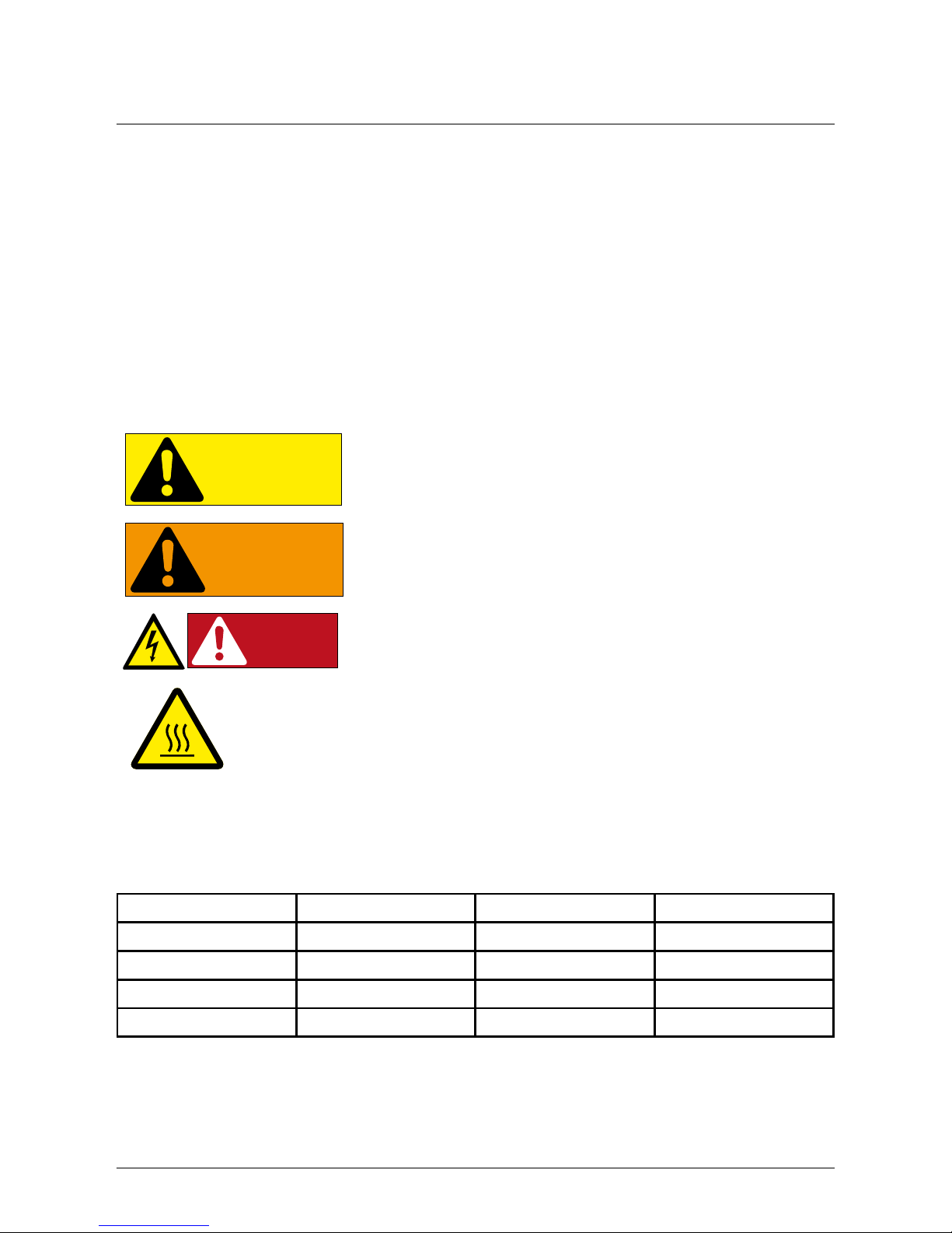
2.2 Safety Symbols & Instruction
CAUTION!
CAUTION!
Machine and equipment damage may occur if
this hazardous situation is not avoided
WARNING!
WARNING!
Death and serious injury may occur if this
hazardous situation is not avoided
DANGER!
DANGER!
Death and serious injury will occur if this hazardous situation is not avoided
WARNING! BURN HAZARD
The enclosure temperature may exceed 70° C
while inverter is in operation. A dangerous burn
hazard is present in this situation. Please do
not touch!
2.3 Validity
This user manual describes the installation procedures, maintenance, technical data and safety
instruction of the following solar inverter models under the DELTA brand.
Model Software:: DSP ver. Red. ver. Comm. ver.
SOLIVIA 10EUT4TL 1.83 1.36 1.56
SOLIVIA 15EUG4TL 1.83 1.36 1.56
SOLIVIA 20EUG4TL 1.83 1.36 1.56
SOLIVIA 30EUT4TL 1.83 1.36 1.56
The software version of your inverter is found on the inverter display. Please nd more information
in section 7.35 “Inverter Information.”
Page 25

25
EN
General Information
2.4 Product Description
The SOLIVIA 10 TL / 15 TL / 20 TL / 30 TL are 3 phase grid-tied solar inverters with reactive power
control. These devices convert direct current (DC) electricity from photovoltaic power collected
from PV arrays into 3 phase alternating current (AC) to feed the excess capacity back to the local
mains electrical grid. Using cutting-edge technology allows a wide voltage input range (250~1000
V) and high performance efciency based on a user-friendly operation design. In addition, special
DSP (Digital Signal Processor) design decreases the circuit complication and electronic components. Please note that this device does not support off-grid function. The following are the key
features of SOLIVIA 10 / 15 / 20 / 30 TL 3 phase grid-tied solar inverters.
Key Features
● Power Rating: 10 / 15 / 20 / 30 kVA
● Power Balancing (33/67) in asymmetrical dc loading situations
● 3-Phase (3-Phase + N + PE), Grid-tie, Transformerless solar inverter
● Maximum efciency: > 98.0 %
● Europe efciency: > 97.8 %
● Reactive power capability (Cap 0.80 - Ind 0.80)
● Low input current harmonic distortion (THD < 3%) @ full load
● 2 MPP Trackers
● Record up to 30 event logs.
● 5” LCD display
● EPO
The 10 TL / 15TL / 20 TL / 30 TL inverters comply with the latest country regulations and standards. Please see chapter 7 - Operating the PV Inverter for the complete list of compliance
standards.
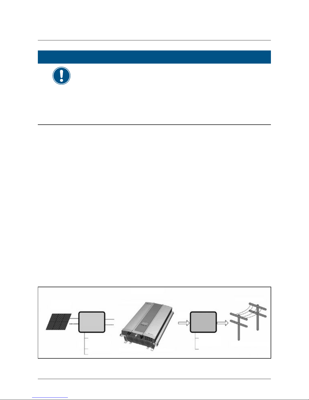
2.5 Application & Intended Use
The operation of the solar inverter is as shown as in the gure 2.1. In order to save energy and
electricity, solar inverters convert the DC input power supplied from the PV array into three-phase
AC output power to the grid.
The solar inverter may be used in the following countries as shown:
Page 26
26
General Information
NOTE
The country list may change due to ongoing certication processes. If you
have any questions, please contact the Delta Support Team.
Countries supported*: Belgium, France, Italy, Netherlands, Spain, Greece,
Germany, Czech Republic, Slovakia, Slovenia, Portugal, Bulgaria, Roma-
nia, United Kingdom, United Kingdom (240 V), Australia, French Islands,
Denmark.
Language supported: English, Italian, French, German, Dutch, & Spanish
*Please note at the time of printing, all countries shown may not necessarily be available for 30
TL model, but are expected to be completed within Q1 2013. Please check with the Delta support
team for questions about countries approved.
The solar power inverter may only be used as intended.
Proper use of the solar power inverter meets the following criteria:
● Use in stationary PV systems connected to the local power grid for converting the direct cur-
rent in the PV system to alternating current and feeding it into the grid
● Use within the specied power range (see Sec. 12.1 - Technical Specications) and under
the specied ambient conditions (indoor area or covered outdoor area with up to IP65)
Any of the following uses of the solar power inverter is considered improper:
● Isolated operation: The solar power inverter has anti-islanding and other monitoring features.
● Use in mobile PV systems.
2.6 Additional Information
For more detailed information about the SOLIVIA 10 TL, 15 TL, 20 TL, and 30 TL or other related
product information, please visit the website at http://www.solar-inverter.com for more support.
Solar Inverter
PV Array
Electrical Grid
3-Phase, N, PE
Surge arrestor
DC Distribution
Box
AC Distribution
Box
Fuse
DC Switch
Surge arrestor
AC breaker
3PH
Figure 2.1.: Solar Inverter System Operation Illustration
Page 27

27
EN
General Information
2.7 Monitoring
The SOLIVIA TL inverters include a display for monitoring performance on location. Remote monitoring is also an option. The 10 TL, 15 TL, 20 TL, and 30 TL with Solar Log and Meteocontrol as
well as Delta’s own monitoring solution, SOLIVIA Monitor G2. Please contact your Delta supplier
for more information on these remote monitoring options.
SOLIVIA Monitor G2 ensures reliable operation and maximum performance of PV systems. The
system is compatible with all SOLIVIA String Inverter models from Delta. The all-in-one solution
is made up of the SOLIVIA GW M1 G2, a gateway that acts as an interface, and an online portal
that is available to users at http://monitoring.solar-inverter.com. Both real-time data reports and
historical data statistics can be generated and exported as a CSV or Excel le. Automated alert
messages notify the operator and ensure that the solar investment pays off. The installer also has
the opportunity to manage its customers’ systems in order to gain a quick overview of the system
status at all times. What’s more, the user receives information on the weather and also the latest
news via the integrated news feed.
For more information about technical features and functions, please refer to the company website
at the following link: http://www.solar-inverter.com/eu/en/SOLIVIA-monitoring-system.htm.
Page 28
28
Preparing for Installation
3. Preparing for Installation
3.1 Instruction before Installing
Due to the variety of user installation environments, reading the manual thoroughly before installation is strongly recommended. All the installation and start-up procedures must be undertaken by
a professional and well-trained technician.
3.2 Checking the Package
There might be some unpredictable situations during transportation. Please check if there is any
damage to the cardboard carton. After opening the package, please check both the outer case
and inner part of this inverter as below.
1. Check the right side on the inverter case to ensure the model number and the specication is
the same with the model you have purchased.
2. Check if there are any loose components.
3. Check if all the accessories are in the package, the standard accessories are listed in the
below table:
Item Quantity Description
10 TL, 15 TL, 20 TL, or 30 TL
Solar Inverter
1 10 kVA,15 kVA, 20 kVA, or 30 kVA solar inverter
User Manual 1 User installation and operation instructions
AC Plug 1 Connector for AC connection
Mounting Bracket 1 Bracket to install the inverter on the wall
Table 3.1.: Packing List
NOTE
When there is outer or inner damage on the inverter or there is any missing
or damaged standard accessories, please contact your inverter supplier for
support.
Page 29
29
EN
Preparing for Installation
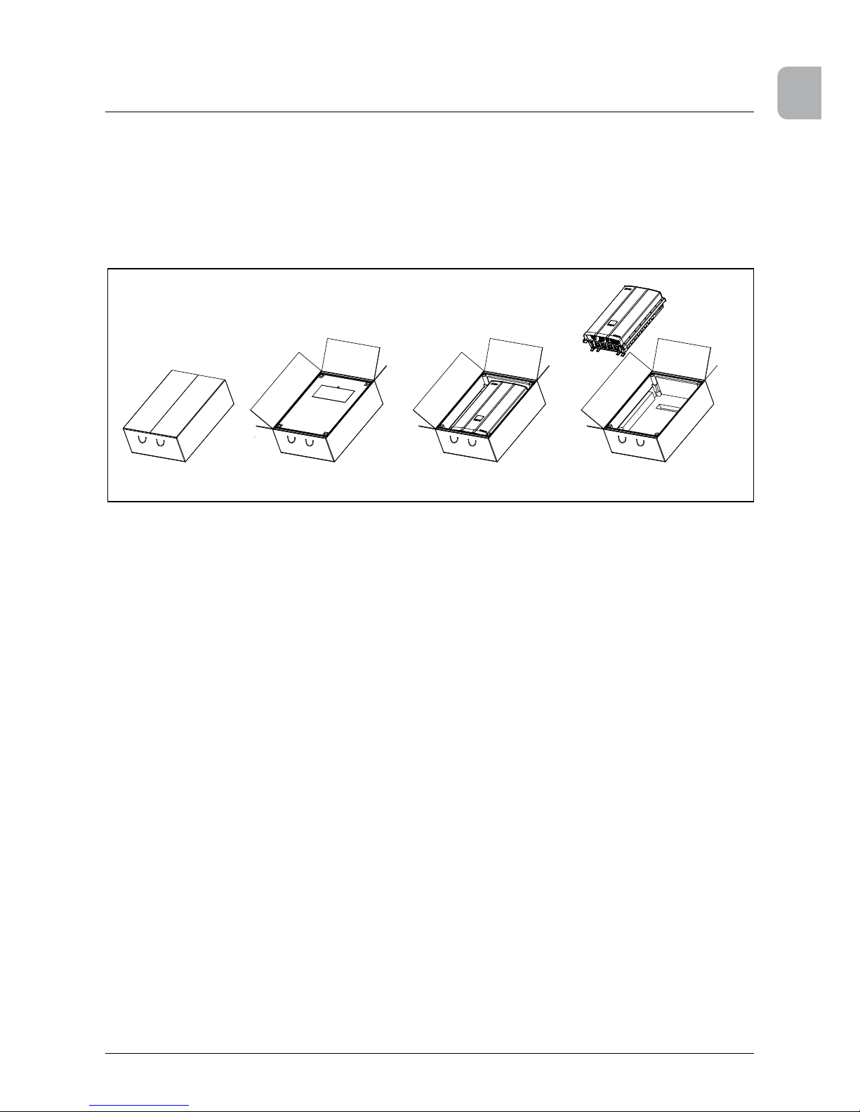
3.3 Unpacking
1. Open the top of the cardboard box as shown in the gure below.
2. Remove the top packing material after opening the box.
3. Lift the Inverter out of the package and save the packaging in case of return.
Figure 3.1.: Unpacking Process
Page 30
30
Preparing for Installation
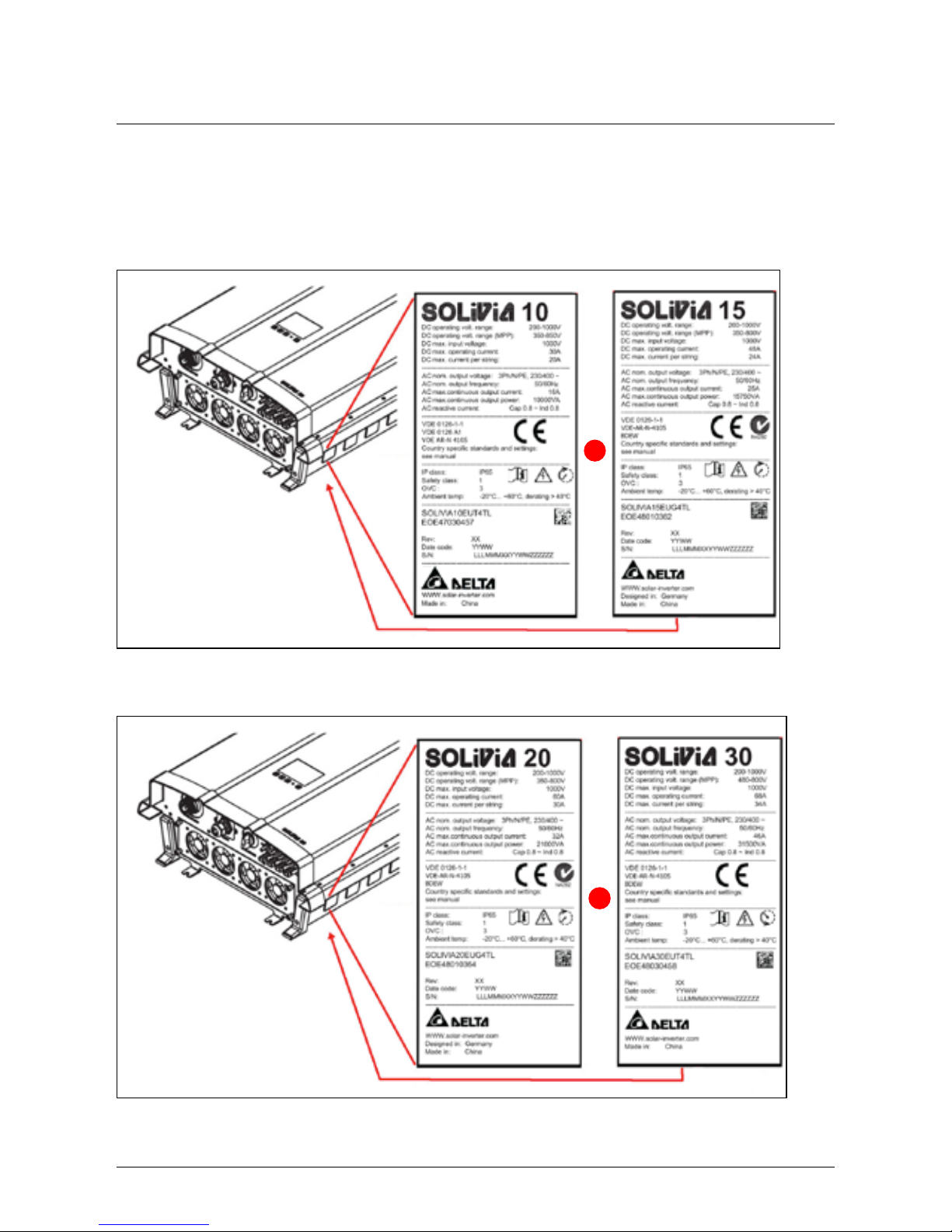
3.4 Identify the Inverter
User can identify the model number by the information on the product label. The model number,
specication as well as the series no. is specied on the product label. In regard to the label location, please refer to the below gure.
or
Figure 3.2.: The Type Label 10 TL and 15 TL
or
Figure 3.3.: The Type Label 20 TL and 30 TL
Page 31

31
EN
Product Overview
4. Product Overview
4.1 Dimensions SOLIVIA 10 TL
625 [24.6] 275 [10.83]
618 [24.3]
Bottom view
Rear viewSide view
Front view
Top view
Figure 4.1.: Dimensions of SOLIVIA 10 TL
Page 32

32
Product Overview
4.2 Dimensions SOLIVIA 15 TL, 20 TL, 30 TL
Bottom view: 15 TL / 20 TL
Rear viewSide view
Front view
275 [10.83]
625 [24.6]
Top view
Figure 4.2.: Dimensions of SOLIVIA 15 TL / 20 TL / 30 TL
Bottom view: 30 TL
Page 33

33
EN
Product Overview
4.3 Function Introduction
Inverter exterior features are shown on gure 4.3 and 4.4, and a more detailed description is
found in the sections from 4.3.1 to 4.3.3
*Note: The fan is shown without
the required protective screen for
illustrative purposes
Communication
Connections
LCD/LED Display
Buttons
Label
Air outlets
DC Connectors
AC Connector
Fan
Figure 4.3.: 10 TL Inverter Exterior View
Page 34

34
Product Overview
Communication
Connections
LCD/LED Display
Buttons
Label
Air outlets
DC Connectors
AC Connector
Fan *4
*Note: The fans shown are without
the required protective screen for
illustrative purposes
Please note the 15 TL / 20 TL model
is shown here. The 30 TL will look
slightly different - a different AC
connector and 2 addl. DC inputs will
be present on the 30 TL.
Figure 4.4.: 15 TL / 20 TL / 30 TL Inverter Exterior View
➀
Figure 4.5.: Grounding Kit
Page 35

35
EN
Product Overview
The chassis has a predrilled hole ➀ to accept a grounding screw as shown. The maximum torque
of the M6 grounding screw is 4.4 Nm. There is a 15 mm diameter unpainted surface around the
center of the ground screw hole that allows for a solid ground connection when installing the
grounding kit.
4.3.1 LCD Display and Buttons
ESC: ESC MENU
DOWN: MOVE DOWN
UP: MOVE UP
ENTER: ENTER MENU OR CONFIRM
LED Indicator (GRN/RED)
LCD Display
Figure 4.6.: LCD Display and Control Panel
Page 36

36
Product Overview
4.3.2 Inverter Input/Output Interface
➀ ➁
➂
➃
DC input panel for the 10
TL, 15 TL, and 20 TL has 4
DC inputs. The 30 TL DC
input interface shown
below, provides 6 DC
inputs.
SOLIVIA 30 EUT4TL
Figure 4.7.: Input/Output Interface
No. Designation Description
➀
AC connector 400 VAC for 10 / 15 / 20 TL ; 500 VAC for 30 TL
➁
Communication 2 × RS485, 1 × EPO, 2 × Dry contact
➂
DC connector 4 Strings (10 TL / 15 TL / 20 TL), 6 Strings (30 TL)
➃
Fans 4 Fans (10 TL model with only one fan)
NOTE
The fans shown are without the required protective screen for illustrative
purposes. The 15 TL, 20 TL and 30 TL models have 4 fans in the fan tray,
whereas the 10 TL will only have one fan.
Page 37

37
EN
Product Overview
4.3.3 Air outlet
air outlet
air inlet
Figure 4.8.: Air Outlet Illustration
There are 4 fans in the bottom section of the inverter and all fans work synchronously. If any one
fan locks up or is defective, it will cause a fan failure and power derating. If you suspect that there
is a problem with a fan please call the Delta support hotline.
Fan
Figure 4.9.: Fan Control 10 TL
Page 38

38
Product Overview
Fan #1 #2 #3 #4
Figure 4.10.: Fan Control 15 TL and 20 TL
Fan #1 #2 #3 #4
Figure 4.11.: Fan Control 30 TL
Page 39

39
EN
Installation
5. Installation
5.1 Installing Location
The SOLIVIA TL inverters can be installed indoors and in protected outdoor areas due to its enclo-
sure protection classes IP65 and IP55. See the gure 5.1 for further explanation of the protection
classes.
WARNING
Death and serious injury may occur if the following instructions are
not carefully followed
► Do not install the unit near/on ammable objects.
► Do not install the unit at a location that people can gain entry/touch
easily.
► Mount the unit tightly onto a solid/ smooth wall.
► In order to ensure the safety of installers, there should be at least two
people to handle the installation.
► When moving the SOLIVIA TL, installer should not stand under material
handling machines.
► Dusty conditions can impair the unit’s performance
WARNING
► According to the Australian/New Zealand standard AS/NZS 5033:2005,
PV arrays for installation on domestic dwellings should not have a maxi-
mum voltage greater than 600 V. For non-domestic installations where
the PV array maximum voltage exceeds 600 V, the entire PV array and
associated wiring and protection, should have restricted access, only
accessible to authorized personnel.
CAUTION
Machine and equipment damage may occur.
► Do not install the unit at a location that has direct exposure to sunlight.
Page 40

40
Installation
IP65 protection class
IP55 protection class
Note: 15 and 20 TL pictured. 10 TL and 30
TL may look slightly different.
Figure 5.1.: SOLIVIA 10 TL, 15 TL, 20 TL, 30 TL protection classes
NOTE
The fans shown are without the required protective screen for illustrative
purposes. The 15 TL, 20 TL and 30 TL models have 4 fans in the fan tray,
whereas the 10 TL will only have one fan.
The upper section of the inverter, shown in the darker tone above, is sealed from the lower section
and rated at IP65 enclosure protection. The lower section of the inverter, containing the cooling
mechanisms, is rated at IP55 enclosure protection.
5.2 Mounting
This unit utilizes a wall mounting system. Please ensure the installation is perpendicular and
with the AC plug at the bottom. Do not install the device on a slanted wall. The dimensions of the
mounting bracket are shown in the following gures. There are 12 pcs. of M6 screws required for
attaching the mounting plate to the wall. Attach the mounting plate securely to the wall, before
attaching the inverter on the mounting plate.
NOTE
Please ensure you are using the correct fastener for the material you are
attaching the inverter mounting plate to.
Page 41

41
EN
Installation
Wall
Unit: mm
6 pcs. screws
6 pcs. screws
SOLIVIA 10 TL rear view
SOLIVIA 15 TL, 20 TL, 30 TL
rear view
Note: The wall mount bracket will be the same part for the
10 TL / 15 TL / 20 TL / 30 TL.
Figure 5.2.: Attaching the mounting bracket to the wall
Page 42

42
Installation
Figure 5.3.: Correct and Incorrect Installation Illustration
CAUTION
Machine and equipment damage may occur.
► Please leave an appropriate gap in between when installing single /
several DELTA solar inverter systems.
► Please install solar inverters at eye level to allow easy observation for
operation and parameter setting.
► Please install solar inverter in a clean and open space.
► The ambient temperature should be between -20°C ... +60°C.
There should be sufcient space for product operation as shown in the gure 5-4. If necessary, the
installer should increase the gap space for optimum product performance.
Page 43

43
EN
Installation
Figure 5.4.: Proper Installation Gap
5.3 Ambient temperature
The solar inverter can be operated in an ambient temperature between -20 °C ... +60 °C. The following diagram illustrates how the power supplied by the solar inverter is reduced automatically in
accordance with the ambient temperature. The device should be installed in a well-ventilated, cool
and dry location.
Page 44

44
Installation
40 74
Pout_max
(kVA)
Ambient
Temperature
(℃)
~
~
~
~
15 kVA / 20 kVA
-20 -15
Figure 5.5.: Derating curve for 10 TL, 15 TL, 20 TL and 30 TL
Page 45

45
EN
Wiring the Inverter
6. Wiring the Inverter
6.1 Preparation before Wiring
1. To avoid accidents, please conrm that the PV inverter’s power of both DC and AC are
switched off.
2. Please conrm whether the input/output of PV inverter’s wiring are clearly indicated. Make
sure that the value, polarity, voltage and phase are correct.
3. The wiring procedure of a PV system is shown in gure 6-1 and 6-2. Wiring details are described in the following paragraphs.
– When the DC input is oating, an external transformer is not necessary. Please refer
to Figure 6-1 for the connection. The inverter can accept DC inputs in parallel (1 MPP
tracker) or separate DC input connections (2 MPP Trackers).
– When an asymmetrical DC load is detected, the solar inverter will automatically adjust
for optimum output. Please see section 6.3.1 for more details. This is useful where
there are two strings of modules on roof surfaces with different orientations, such as in
the case of a dormer with north & south facing surfaces.
CAUTION
Machine and equipment damage may occur.
► When the DC input is a positive ground or negative ground, all of the
strings must be connected in parallel and then connected to the inverters. In addition, an external isolation transformer must be installed on
the AC side, otherwise, damage will result and the inverter will not work
properly. Different DC input wiring needs require different insulation
detection settings. To learn more about the settings, please refer to
„6.3.6.2 Install Settings“ on page 54.
Page 46

46
Wiring the Inverter
Parallel or
Separate
PV Array
DC Distribution
Box
DC Wiring
AC
Wiring
Communication
Wiring
Figure 6.1.: Connection of system if DC inputs are oating
Page 47

47
EN
Wiring the Inverter
Must be Parallel
Connection
PV Array
DC Distribution Box
(Plus-GND or Minus-GND)
Isolated
transformer
Utility
3Ph, Δ or Y
230/400 Vac
To Inverter
3Ph, Y
230/400 Vac
or
Must install one
transformer per inverter
Figure 6.2.: Connection of system with Positive Ground or Negative Ground
6.2 AC Grid Connection: 3 Phase + N + PE
WARNING
Death and serious injury may occur
► Before engaging in the AC wiring, please ensure the AC 3-phase power
is switched off.
Page 48

48
Wiring the Inverter
6.2.1 Required protective devices and cable cross-sections
Please use the proper upstream circuit breaker to protect the inverter according to the table:
Model Upstream Circuit Breaker
SOLIVIA 10 TL 20 A
SOLIVIA 15 TL 30 A
SOLIVIA 20 TL 40 A
SOLIVIA 30 TL 60 A
G N L1 L3L2
N
L1
L2
L3
PE
To solar inverter AC
plug
6.2.1.1 Residual Current Devices
The SOLIVIA 10 TL / 15 TL / 20 TL / 30 TL are not capable of feeding in DC residual currents due
to their design. They fulll this requirement in accordance with DIN VDE 0100-712.
The possibilities of faults were examined without taking the integrated residual-current monitoring
unit (RCMU) into account. When examining these faults in terms of the current valid installation
standards, no danger in combination with a type A upstream residual-current device can occur.
Therefore faults that would otherwise require the use of a type B residual-current device due to
the inverter can be excluded.
The integrated all-pole sensitive residual-current monitoring unit (RCMU) results in additional
safety. For all above mentioned transformerless inverters from Delta RCDs of the type A can be
used.
6.2.1.2 AC Cable Requirements
Please use properly sized wire to connect to the correct poles (According to the table below)
Model AC connector* Current
Rating
Min. / Max.
Cable size
allowed
Min. / Max. wire
size allowed in
screw terminals
Torque of
terminal
screws
10 TL / 15
TL / 20 TL
Amphenol C16-3 ≤ 40 A 11 mm
2
/ 20
mm
2
4 mm2 / 8 mm
2
(12 AWG / 9 AWG)
≥ 0.7 Nm (7
kg)
30 TL Amphenol PPC
AC 24
≤ 60 A 22 mm
2
/ 32
mm
2
10 mm2 / 16 mm2
(8 AWG / 6 AWG)
≥ 0.9 Nm
(10 kg)
* Please follow up with Amphenol for the latest information regarding the AC connectors
Table 6.1.: Cable cross sections and torques for AC connectors
Page 49

49
EN
Wiring the Inverter
AC wiring can be separated into 3-phase (L1, L2, L3), N, and PE. The following earthing congurations are allowed. IT is not allowed. Please see the appendix for further explanation of these
earthing systems.
TN-S TN-C TN-C-S TT IT
Yes Yes Yes Yes No
Table 6.2.: Permitted earthing systems
NOTE
TT is not recommended. Have to be sure the voltage of N is very close to
PE (< 20 V
rms
)
6.2.2 AC bayonet connectors for 10 TL, 15 TL, 20 TL
The AC bayonet connectors are approved for cable sheath diameters between 11 mm and 20 mm.
To install an AC cable, rst strip the voltage free line and cable ends as shown below and then
follow the sequence in Figure 6.5 to assemble the cable and bayonnet connector.
52.5 mm (PE 57.5 mm)
10 mm
Figure 6.3.: AC cable stripping requirements for 10 TL, 15 TL, and 20 TL
NOTE
For lines with a cable sheath diameter from 16 mm to 20 mm, the cable
gland must be adapted accordingly. To do this, cut out the inner section of
the blue sealing ring.
In Figure 6.5, the Amphenol C connector shown can be mated with the 10 TL / 15 TL / 20 TL
inverter‘s AC plug. After disassembly of the connector, please adhere to the correct polarity for
proper AC wiring (this product allows either positive or negative phase sequence). That means the
sequence of L1-L3 can be adjusted and the N and PE must be connected.
Page 50

50
Wiring the Inverter
This is a rear view of the cable gland.
For a cable sheath diameter between
16 mm to 20 mm, please remove the
inner sealing ring.
Figure 6.4.: AC plug sealing ring for AC connector 10 TL, 15 TL, and 20 TL
Page 51

51
EN
Wiring the Inverter
Inverter
Next tighten the cable gland ➁ to the connector housing ➀. Tightening torque for cable
sheath diameters between 11 and 20 mm: 6 to 8 Nm. Rotate the coupling ring ➂ to mate
the connector with the inverter‘s AC plug.
After wiring the mating connector, screw
the connector housing ➀ to the coupling
ring ➂. To do this push the coupling ring
➂ to the connector housing ➀ and tighten
1-2 Nm.
Rotate the connector housing and cable
gland to remove them from the coupling
ring.
The female cable
connector needs to
be wired as shown
below.
To wire the connector refer to placement
of L1, L2, L3, N and PE shown to the left.
Screw termination is provided to x the
wires to the contacts.
NOTE: Rear view of cable
connector
L3
L1
L2
PE
1 : L1
2 : L2
3 : L3
4 : N
: PE
N
L1
L2
L3
N
PE
Cable
Slide the connector housing and cable
gland onto the cable.
➀
➁
➂
Figure 6.5.: AC connector 10 TL, 15 TL, and 20 TL
Page 52

52
Wiring the Inverter
CAUTION
Machine and equipment damage may occur.
► Observe the pin assignment of the AC bayonet connector. An incorrect
assignment can result in the unit being destroyed. The Figure 6.5 pin
out diagram shows the connections inside the AC connector.
NOTE
Make sure the line is provided with a strain relief device. When using cables
with a diameter of less than 13 mm (11 mm ... 13 mm diameter cable
require strain relief), the cable must be relieved just behind the connector.
6.2.3 AC bayonet connectors for 30 TL
The AC bayonet connector for 30 TL are approved for cable sheath diameters between 22 mm
and 32 mm. To install an AC cable, rst strip the voltage free line and cable ends as shown below
and then follow the sequence in Figure 6.7 to assemble the cable and bayonnet connector.
60 mm (PE 65 mm)
12 mm
Figure 6.6.: AC cable stripping requirements for 30 TL
In Figure 6.7, the Amphenol PPC AC 24 connector shown can be mated with the 30 TL inverter‘s
AC plug. After disassembly of the connector, please adhere to the correct polarity for proper AC
wiring (this product allows either positive or negative phase sequence). That means the sequence
of L1-L3 can be adjusted and the N and PE must be connected.
Page 53

53
EN
Wiring the Inverter
Inverter
Next tighten the cable gland body ➁ to connector housing ➀ and the
cable gland cap ➂ to the cable gland body ➂. Tightening torque for
cable sheath diameters between 22 and 32 mm: 6 to 8 Nm. Rotate
the coupling ring ➃ to mate the connector with the inverter‘s AC plug.
After wiring the mating connector, screw the
connector housing ➀ to the coupling ring ➃. To
do this push the coupling ring ➃ to the connector housing ➀ and tighten 1-2 Nm.
Rotate the connector housing ➀ and cable
gland body ➁ and cable gland cap ➂ to
remove them from the coupling ring.
The female cable
connector needs to
be wired as shown
below.
To wire the connector refer to placement
of L1, L2, L3, N and PE shown to the left.
Screw termination is provided to x the
wires to the contacts.
NOTE: Rear
view of cable
connector
L1
L2
L3
N
PE
Cable
Slide the connector housing, cable gland
body and cable gland cap onto the cable.
L3
L1
L2
N
PE
Cable
➀
➂
➁
➃
➀
➂
➁
➀
➁
➂
Figure 6.7.: AC connector for 30 TL
Page 54

54
Wiring the Inverter
6.2.4 AC Wiring Considerations
The connection to the Amphenol AC connector for all models can be made with a exible or
rigid cable with a copper conductor that has the appropriate cross section according to table 6.1
and which has an installation condition that gives a correction factor equal to one. The AC cable
should be protected by a minimum type B 40 Amp breaker for 10 TL / 15 TL / 20 TL and minimum
type B 60 Amp breaker for 30 TL.
This connector is developed for connection to copper wires (for other applications please contact
Amphenol). The cross section of the cable should be calculated by considering the material used,
thermal conditions, length of the cable, the type of installation, and AC voltage drop.
Please note the cable length and the cable cross-section, due to the risk of undesirable temperature rise and power losses. In some countries, (e.g. France, Germany, Australia) system installation requirements have to be followed (UTE 15712-1, VDE 0100 712, AS/NZS 5033:2005). This
recommendation will dene minimum cable sections and protections against overheating due to
high currents. Please make sure that you follow specic requirements in your country.
For the security of your installation and for the safety of the user, please install required safety and
protection devices that are applicable for your installation environment (example: automatic circuit
breaker and/or overcurrent protection equipment).
WARNING
Death and serious injury may occur
In the case of damage or bodily harm resulting from the use of this device
in a way contrary to it’s intended purpose or as a result of unauthorized
modications made to the parameters of the inverter, Delta will not be held
liable in these situations..
The solar inverter must be grounded via the AC connector’s PE conductor. To do this, connect the
PE conductor to the designated terminal.
The AC connector is protected from unintentional disconnection by a clip mechanism which can
be released with a screwdriver.
The AC voltage should be as follows:
● L1-N: 230 V
AC
● L2-N: 230 V
AC
● L3-N: 230 V
AC
6.3 DC Connection (from PV array)
WARNING
Death and serious injury may occur
► When doing DC wiring, please ensure the wiring is connected with the
correct polarity.
► When doing DC wiring, please conrm that PV array’s power switch is
off.
Page 55

55
EN
Wiring the Inverter
➀ ➁
➂
➃
DC input panel for the 10
TL, 15 TL, and 20 TL has 4
DC inputs. The 30 TL DC
input interface shown
below, provides 6 DC
inputs.
SOLIVIA 30 EUT4TL
Figure 6.8.: Input/Output Interface
No. Designation Description
➀
AC connector 400 VAC for 10 / 15 / 20 TL ; 500 VAC for 30 TL
➁
Communication 2 × RS485, 1 × EPO, 2 × Dry contact
➂
DC connector 4 Strings (10 TL / 15 TL / 20 TL), 6 Strings (30 TL)
➃
Fans 4 Fans (10 TL model with only one fan)
NOTE
The fans shown are without the required protective screen for illustrative
purposes
CAUTION
Machine and equipment damage may occur.
► The connection number of PV ARRAY, open circuit voltage and power
of String_1 and String _2 must be coherent.
► The connection number of PV ARRAY, open circuit voltage and power
of String _3 and String _4 must be coherent.
► The maximum open circuit voltage of PV Array must not exceed 1000 V.
► The range of V
mpp
of Input DC1 and Input DC2 shall be 350~800 VDC.
► The device installed between PV array and inverter must meet the rat-
ing of voltage <1000 VDC and < short current.
► The input power connected to the inverter must not exceed the maxi-
mum rating of input power as shown in the table below.
Page 56

56
Wiring the Inverter
Maximum rating of input power:
Type of limit 10 TL 15 TL 20 TL 30 TL
Total input power 11 kW 16.5 kW 22 kW 30 kW
Input 1 & Input 2 7.3 kW 11 kW 14.7 kW 20.1 kW
Cable size:
Current rating Wire size
DC 34 A 5-6 mm
2
/ 10 AWG
DC wiring polarity is divided into positive and negative, which is shown in Figure 6-9. The connection should be consistent with the indicated polarity marked on the inverter.
Figure 6.9.: DC Wiring Illustration
6.3.1 Asymmetrical Loading for 10 TL, 15 TL, 20 TL, and 30 TL
The inverters operate using two separate MPP trackers that can handle both symmetrical and
asymmetrical loads to allow for optimum adjustment. This allows for the requirements of complex
PV system designs to be fullled. For example: east/west-facing roof (symmetrical load) or a
south facing roof such as a dormer (asymmetrical load).
See the following gures for explanation of how symmetrical and asymmetrical loading are
handled:
Page 57

57
EN
Wiring the Inverter
Input Current 1
Input Current 2
Input Current [A]Input Current [A]
Input Voltage [V ]
Input Voltage [V ]
Balanced Input Power
Unbalanced Input Power 33/67
Input Current 1
Input Current 2
Max. Power MPPT Range
Max. Power MPPT Range
Max. Current
Max. Current
Figure 6.10.: Comparison diagram of Balanced Power Input and Unbalanced Power Input
Maximum rating of input power:
Model Max. Input Current Max. Power MPPT
Range balanced
(50/50)
Max. Power MPPT
Range unbalanced
(33/67)
SOLIVIA 10 TL 20 A x 2 350 - 850 Vdc 350 - 850 Vdc*
SOLIVIA 15 TL 24 A x 2 350 - 800 Vdc 470 - 800 Vdc
SOLIVIA 20 TL 30 A x 2 350 - 800 Vdc 480 - 800 Vdc
SOLIVIA 30 TL 34 A x 2 480 - 800 Vdc 620 - 800 Vdc
*Note: Unlike the 15 / 20 / 30 TL, the 10 TL has a xed max. power MPPT voltage range. For
unbalanced loads, the 10 TL will adjust the input current to provide an optimum adjustment.
Page 58

58
Wiring the Inverter
A kit to meet UTE 15712-1 requirements is provided for the SOLIVIA 15 TL and 20 TL and can be
ordered from Delta with the part number in the following table.
Designation Part number Delta
UTE kit Multi-Contact*
*Kit contains caps for 4 strings. For 30
TL, 2 additional caps will be needed
since 6 strings are available..
EOE90000341
6.4
The best efciency of the solar inverter is obtained at an input voltage of 640 V.
0
0.2
0.4 0.80.6 1
350 V 640 V 800 V
96
98
88
90
92
94
86
84
82
80
Efficiency [%]
Power
Figure 6.11.: SOLIVIA 10 TL Efciency Curve
Page 59

59
EN
Wiring the Inverter
0
0.2
0.4 0.80.6 1
350 V 640 V 800 V
96
98
88
90
92
94
86
84
82
80
Efficiency [%]
Power
Figure 6.12.: SOLIVIA 15 TL Efciency Curve
0
0.2
0.4 0.80.6 1
350 V 640 V 800 V
96
98
88
90
92
94
86
84
82
80
Efficiency [%]
Power
Figure 6.13.: SOLIVIA 20 TL Efciency Curve
Page 60

60
Wiring the Inverter
0
0.2
0.4 0.80.6 1
350 V 640 V 800 V
96
98
88
90
92
94
86
84
82
80
Efficiency [%]
Power
Figure 6.14.: SOLIVIA 30 TL Efciency Curve
6.5 Communication Module Connections
The communication module supports the communication functions with a computer, also provides
1 EPO (Emergency Power Off) and 2 sets of dry contacts. The parts of the communication module
are shown in Figure 6.15. The function of each part is detailed in sections 6.5.1 ... 6.5.3.
Page 61

61
EN
Wiring the Inverter
1.
2.
3.
Dry contact
EPO
(Emergency
Power Off)
RS485
Dip Switch
to activate
the terminal
resistor
Dip Switch
to activate
the terminal
resistor
RS485
EPO
(Emergency
Power Off)
Dry contact
15 TL / 20 TL / 30 TL 10 TL
Figure 6.15.: Communication module removal
To remove the communication module follow these instructions:
1. Unscrew and remove the two Phillips screws highlighted above in Figure 6.15.
2. Remove the front plate as shown.
3. Carefully pull out the communication module from the inverter. Remove glands and plugs
where applicable.
Page 62

62
Wiring the Inverter
6.5.1 RS485 Connection
The pin denition of RS485 is shown in Table 6.3. The wiring of multi-inverter connections is
shown in Figure 6.16.
PIN FUNCTION
4 GND
7 DATA+
8 DATA-
Table 6.3.: Denition of RS485 pin
4 GND
7 DATA+
8 DATA-
Inverter #1* Inverter #2 Inverter #N
Every inverter must have a different ID setting in the same chain.
Terminal Resistor:
120Ω (0.5W)
Data + to Data -
*Activate the Terminal Resistor by setting
the internal dip switch no. 2 to on. See Figure 6-17 for this procedure.
Figure 6.16.: Multi-inverter connection illustration
Page 63

63
EN
Wiring the Inverter
Figure 6.17.: Terminal resistor switch for Multi-inverter Connection
To engage the internal Terminal Resistor, place switch number 2 on the communication module in
the on position. See gure 6.17 for more information.
Baud Rate Programmable, 2400/4800/9600/19200/38400, default = 19200
Data Bit 8
Stop Bit 1
Parity N/A
Table 6.4.: RS485 Data Format
6.5.2 EPO (Emergency Power Off) Connections
The SOLIVIA 10 TL / 15 TL / 20 TL / 30 TL provides two sets of emergency power off functions.
When the outer external switch is shorted, the inverter will shut down immediately. Please see
Table 6.5 for the pin denition.
PIN
1 EPO1
2 EPO1
3 N/A
4 EPO2
5 EPO2
6 N/A
7 N/A
8 N/A
Table 6.5.: EPO pin assignment
Page 64

64
Wiring the Inverter
NOTE
To shutdown the inverter, short pin 1 and 2 or short pin 4 and 5.
6.5.3 Dry Contact Connection
Provides 2 sets of Dry Contact functions - NO1 and NO2. Please refer to Figure 6.16 for connection diagram and read below for more details.
NO1: When a fault is detected, COM and NO1 will be shorted.
NO2: When the inverter is on grid, the COM and NO2 will be shorted.
COM
NO1: Fault
NO2: On Grid
Figure 6.18.: Dry contact connection
Page 65

65
EN
Operating the PV inverter
7. Operating the PV inverter
WARNING
Burn hazard!
The enclosure temperature may exceed 70° C while in operation. Injury
may occur owing to the hot surface.
► Please do not touch!
After installation, please conrm the AC, DC, and Communication connections are correct. Follow
the steps below to startup the inverter:
1. Check the PV array DC voltage:
– Uncover the PV arrays and expose them to full sunlight.
– Measure the PV array open circuit DC voltage across the DC positive (+) and negative
(-) terminals in the DC distribution box. This voltage must be greater than 250 V
DC
and
less than 1000 VDC.
2. Check the AC utility voltage:
– Using an AC voltmeter to measure the AC utility voltage and ensure the voltage is at ap-
proximately the nominal value (Nominal = 230 Vac Line-N).
3. Set all necessary settings:
– Switch on AC breaker to provide power to the inverter (40 seconds)
– Check the inverter display.
– Country & Language settings appear on the display at rst startup.
NOTE
The country list may change due to ongoing certication processes. If you
have any questions, please contact the Delta Support Team.
Countries supported*: Belgium, France, Italy, Netherlands, Spain, Greece,
Germany, Czech Republic, Slovakia, Slovenia, Portugal, Bulgaria, Romania, United Kingdom, United Kingdom (240 V), Australia, French Islands,
Denmark.
Language supported: English, Italian, French, German, Dutch, & Spanish
*Please note at the time of printing, all countries shown may not necessarily be available for
30 TL model, but are expected to be completed within Q1 2013. Please check with the Delta
support team for questions about countries approved.
The next step is to set up the inverter for the appropriate grid on the rst startup. The grid selection for each inverter model can be found on the following list:
Page 66

66
Operating the PV inverter
Grid (As shown
on the Display)
Description 10 TL 15 TL 20 TL 30 TL
Australia
Australia AS 4777 x x
Belgium
Belgium as per C10/11, June 2012 x x
Bulgaria
Bulgaria as per VDE 0126 x x
Czech
Czech Republic as per VDE 0126 x x
Denmark
Denmark as per VDE AR N 4105 x x
France
France as per UTE 15 712-1 x x
France (60Hz)
French Islands 60 Hz x x
Germany (VDE0126)
Germany as per VDE 0126 x x x
Germany (LVD)
Germany as per VDE AR N 4105 x x x x
Germany (MVD)
Germany as per BDEW x x
Greece
Greece as per VDE 0126 x x
Italy BT CEI 0-21
Italy as per CEI 0-21:2012-06 for PV Installations smaller or
equal to 6 kW
x x x
Italy MT A70
Italy as per CEI 0-21:2012-06 for PV Installations larger
than 6 kW
x x x
Netherlands
Netherlands as per VDE 0126 + EN 50438 x x
Portugal
Portugal as per EN 50438 x x
Romania
Romania as per VDE 0126 x x
Slovakia
Slovakia as per VDE 0126 x x
Slovenia
Slovenia as per SONDO Class C x x x
Spain (RD661)
Spain as per RD 661 x x
Spain (RD1663)
Spain as per RD 1663 x x
Spain (RD1699)
Spain as per RD 1699 x x
UK
United Kingdom G59-2 230 V x x
UK (240)
United Kingdom G59-2 240 V x x
Figure 7.1.: Country Settings on initial startup
– Set all settings for Date, Time, Inverter ID, Insulation, etc.
Page 67

67
EN
Operating the PV inverter
NOTE
► If selecting Germany or Italy as the country, it could be necessary to
adjust active and reactive power settings (Information for the settings
will come from the local grid operator).
► If needed please call the local support hotline for assistance in setting
up Germany MVD/LVD or Italy CEI 0-21/A70 grid settings.
4. Start up the inverter:
– After nishing the basic settings, turn on DC switches (including the DC switch in in-
verter), inverter will do some self-tests and start a countdown if there is no problem.
– When operating, check all information on the display is correct (ex. Input voltage, current
and power; output voltage, current, power and frequency)
When solar irradiation is sufcient, the device will operate automatically, after the self-auto test is
completed successfully (about 2 minutes on the rst startup of a day). Please refer to Figure 7.2
showing the LCD Display and Control Panel details. The display includes a 5“ graphic LCD with
320x240 dots of resolution and a LED indicator showing inverter status. There are green and red
colored LED indicator lights to represent various inverter states of operation. Please refer to Table
7-1 for more detail on the LED indicator.
ESC: ESC MENU
DOWN: MOVE DOWN
UP: MOVE UP
ENTER: ENTER MENU OR CONFIRM
LED Indicator (GRN/RED)
LCD Display
Figure 7.2.: LCD Display and Control Panel
Page 68

68
Operating the PV inverter
Inverter Status Green LED Red LED
Standby or Countdown FLASHING - on 1 sec. and off
1 sec.
OFF
Power ON ON OFF
Error or Fault OFF ON
Night time (No DC) OFF OFF
Bootloader mode FLASHING - on 1 sec. and off 1 sec., rst the green LED then
the red LED in alternating sequence
Table 7.1.: LED indicator
7.1 Disconnection Parameter Settings
7.1.1 Power Disconnection Device (PDD) Settings
This applies to LVD and MVD settings when selecting the grid as DE LVD or DE MVD.
NOTE
DE LVD refers to Germany Low Voltage Directive and DE MVD refers to
Germany Midvoltage Directive.
Press the buttons
together for more than 5
seconds from any grid setting window to switch off the
power disconnection device.
Figure 7.3.: Grid Settings for LVD and MVD
The grid settings for Germany LVD and MVD can be tuned according to the local utility requirements. The integrated power disconnection device can be set in three modes: 1) set to default
values as recommended by LVD/MVD regulations, or 2) adjustments can be done manually within
the allowed parameter ranges according to the LVD/MVD regulations depending on the selected
mode, or 3) the device can be switched off.
Page 69

69
EN
Operating the PV inverter
At any time, while you are viewing one of the 4 grid setting windows, you are able to switch off the
power disconnection device by simultaneously pressing the up and down buttons and holding for
more than 5 seconds.
See the tables below for the LVD/MVD allowed parameter ranges according to the regulations:
When the selected grid is LVD, the following adjustable vaules are allowed:
Parameter Name in display Adjustable values
Rise-in-voltage protection U> Umax 110 ... 115%
As dened in VDE AR N 4105, only the rise-in-voltage protection Umax shall be designed as
10-minute running mean value protection which prevents the upper voltage limit specied in DIN
EN 50160 from being exceeded (monitoring over the power).
When the selected grid is MVD (BDEW), the following adjustable values are allowed:
Parameter Name in
display
Adjustable
values
Recommended settings of
protection relays as per
BDEW
Rise-in-voltage protection U>> Crit. Umax 1.00 ... 1.30 U
n
1.20 U
ns
≤ 100 ms
Under-voltage protection U< Umin 0.10 ... 1.00 U
n
0.80 U
ns
1.5 - 2.4 s
Under-voltage protection U<< Crit. Umin 0.10 ... 1.00 U
n
0.45 U
ns
300 ms
Rise-in-frequency protection f> Fmax 50.0 ... 52.0 Hz 51.5 Hz ≤ 100 ms
Under-frequency protection f< Fmin 47.5 ... 50 Hz 47.5 Hz ≤ 100 ms
Delay time for U< tUmin 1.5 ... 2.4 s 1.5 ... 2.4 s
Table 7.1.: Recommended settings of protection equipment as per BDEW Technical Guidelines -
June 2008 issue from Table 3.2.3.3 - 2
7.1.2 SPI device
The SPI is a system interface protection device for use in Italy. There is no internal SPI required
for this inverter but an external SPI device may be requested. Care must be taken so disconnection settings on the inverter are set so they do not interfer with external SPI device disconnection
settings. The password “5555” entered in the Install Settings page when Italy is selected as the
Country, enables disconnection parameters to be adjusted directly within the grid settings menu.
Page 70

70
Operating the PV inverter
7.2 Home Page
When the inverter is operating normally, the LCD will show the home page as shown in Figure 7.4.
On the home page the user can nd the output power, inverter status, E-today, date and time.
Actual Power
Date and Time
Today Power
Today Runtime
Inverter Status
Today Power
Curve
Figure 7.4.: Home page
7.3 LCD Flow Chart
Press any button to enter the menu page, the selections are shown in Figure 7.5. E-today is on
the home page; the content of the rest of the pages will be explained in detail from 7.3.1 ... 7.3.6.
Figure 7.5.: Main menu page
Page 71

71
EN
Operating the PV inverter
“„7.3.1 Power Meter“ on page 71
“„7.3.2 Statistics“ on page 71
“„7.3.3 Logs“ on page 72
“„7.3.4 Actual data“ on page 73
“„7.3.5 Inverter Information“ on page 74
“„7.3.6 Settings“ on page 74
7.3.1 Power Meter
Figure 7.6.: Power Meter Pages
7.3.2 Statistics
After pressing ENT on this page, the user can view the historical data about power generation on
a yearly, monthly and daily basis.
Page 72

72
Operating the PV inverter
Figure 7.7.: Statistics Pages
7.3.3 Logs
After pressing ENT on this page, the user can view the internal log and can view the events log.
7.3.3.1 Internal Data
The internal data shows all messages coming from the inverter. These messages indicate the status of internal processes and also changes on the AC and DC terminals, for example: frequency,
voltage, etc.
Figure 7.8.: Internal Data Flow Chart
7.3.3.2 Events Journal (Germany LVD or MVD Grid Only)
The events journal records all events coming through the RS485 link or made on the display at
the user level. Only events that could affect global production are shown in this log.
Page 73

73
EN
Operating the PV inverter
Figure 7.9.: Events Journal Flow Chart
7.3.4 Actual data
Actual data includes 4 pages and records the maximum and/or minimum historical values, including voltage, current, power and temperature.
Figure 7.10.: Actual Data Flow Chart
Page 74

74
Operating the PV inverter
7.3.5 Inverter Information
This page includes the following information: serial number, rmware version, installation date,
and inverter ID. To change the inverter ID, please refer to “„7.3.6.2 Install Settings“ on page 75.
Figure 7.11.: Inverter Information Page
NOTE
The information shown in Figure 7.11 is for illustration purposes and may
not match the actual information displayed on your inverter.
*The last menu items are only applicable for installations in Italy. If
BT CEI 0-21 or Italy MT A70 are selected as the country, then the Country
name will show on the 2nd page. For Italy, the software version will show.
7.3.6 Settings
Settings includes General Settings, Install Settings, and Active/Reactive Power Control.
Figure 7.12.: Settings Page
Page 75

75
EN
Operating the PV inverter
NOTE
FRT is only accessible if you have selected Germany MVD, Italy CEI 021 or
Italy A70 as your grid selection.
7.3.6.1 General Settings
Settings in the General Settings include Language, Date, Time, Screen Saver, Brightness, Contrast, Baud Rate, CO2 saved, Earning Value, and Currency.
Figure 7.13.: General Settings Page
User can set the Language, Date, Time, Screen Saver, LCD Brightness, and Contrast appear on
the General Settings page 1. Screen Saver can be adjusted from 5 minutes to 60 minutes. When
over the setting time limitation, without the pressing of any buttons, the LCD backlight will go off
automatically. Brightness and contrast can be adjusted from 1-5 levels (low to high). On General
Settings page 2 the Baud Rate, CO2 Saved, Earning Value and Currency are adjustable. Cur-
rency is selectable as Australian Dollar (AUD), Euro (EUR) and Great Britian Pound (GBP).
7.3.6.2 Install Settings
Correct passwords are requested when entering Install Settings. Install Settings for user and
installation technicians are different. The password can not be revised. After conrmation of the
installer password (5555), user can set Inverter ID and Insulation settings. Country is viewable but
not adjustable.
Page 76

76
Operating the PV inverter
Password is 5555.
Figure 7.14.: Install Settings Page - Installer Mode
● Inverter ID: This setting is used to set unique ID‘s for installations with more than one
inverter. In a multi-inverter installation where the inverters will be in a network, each inverter
must have a unique ID.
● Insulation: ON means enable the measurement of impedance between Array and PE, will
not connect to Grid if failure. Depending on DC wiring conditions, user can set 6 kinds of
insulation detecting methods - ON, Positive Ground, Negative Ground, DC1 only, DC2 Only,
or Disable. Installer can select different resistance criteria according the actual conditions.
● Country: This is the Country selected during startup (nonadjustable).
Figure 7.15.: Insulation Settings - Installer Mode
7.3.6.3
Active/Reactive Power control for DE LVD and DE MVD
Below is an overview of the features that are adjustable to control the production of active and
reactive power for Germany LVD and MVD
Feature Available for Description
LVD MVD
Active power control
Page 77

77
EN
Operating the PV inverter
Feature Available for Description
LVD MVD
Power limit x x To reduce the maximum power
production
Power vs. frequency x x To set the power gradiant in
dependency of the frequency
Reactive power control
Constant cos φ x x To set a xed cos φ (inductive or
capacative)
cos φ (p) x x To set a cos φ (inductive or
capacative) in dependency of
the active power ratio P/P
n
Constant reactive power x To set the reactive power ratio
Q/Sn. For MVD grids only.
Q (V) x To set the reactive power ratio
Q/S
n
in dependency of the volt-
age V. For MVD grids only.
Figure 7.16.: Active/Reactive Power settings page
Note: Before adjusting the Active/Reactive Power settings, a Warning window will be displayed,
that you should read and make a selection to continue or to quit. Please see caution messages
below related to adjusting the settings.
Page 78

78
Operating the PV inverter
CAUTION
Machine and equipment damage may occur.
► Please only adjust active and reactive power settings if you are a quali-
ed electrical technician with the knowledge to do so
► Adjustments may affect energy production
► Some values entered in the Active/Reactive Power settings must come
from the local grid operator. Please check with them before making any
adjustments
7.3.6.3.1 Power Limit
User can select set percentage of actual or rated power to limit inverter’s output power. Inverter
will start the action once the user sets the Mode to “ON”. This feature is available for LVD and
MVD grids.
Figure 7.17.: Power Limit settings page
Page 79

79
EN
Operating the PV inverter
A
B
8:00 12:004:00 16:00 20:00 00:00
100%
75%
50%
25%
0%
output poweroutput power
8:00 12:004:00 16:00 20:00 00:00
100%
75%
50%
25%
0%
When Actual Power is
selected the output
power is based on the
percentage of the available power (dotted path)
If the set point is 75%
then B=75% of A.
When Rated Power is
selected the output
power is equal to the
nominal output power x
the Set Point. If set at
75% then output power
can not exceed 75% of
nominal power.
available power
output power
available power
output power
Figure 7.18.: Actual Power vs Rated Power
Parameter Adjustable Values Description
Set point 0 ... 100% Sets the power reduction to the adjusted value.
The value is multiplied with the value of the
Locked power limitation.
Actual/Rated Actual | Rated Select Actual or Rated Power
Mode ON | OFF Switches the feature on and off.
7.3.6.3.2 Power vs. Frequency
User can have two modes: LVD and MVD. The gures below explain the different behaviors for
these modes. The inverter activates these modes depending on the country that is selected and
the requirements for that country.
This feature is available for LVD and MVD grids. This feature allows the user to set a power reduction in a percent of the maximum power.
Page 80

80
Operating the PV inverter
P
m
f
start
f
stop
Gradient (%/Hz)
f
(Hz)
P
P
m
P
f
recovery
f
start
f
stop
f(Hz)
Gradient (%/Hz)
Figure 7.19.: LVD Curve power vs. frequency Figure 7.20.: MVD Curve power vs. frequency
NOTE
The Power vs
Frequency function is
required for LVD and
MVD. Please make
sure the Mode is ON
and do not turn off.
Figure 7.21.: Power vs. Frequency
Adjustable parameters
Parameter Adjustable Values Description
Actual / Rated Power Actual or Rated can be selected
Start frequency 50.00 ... 55.00 The frequency when the power reduction starts
Stop frequency Stop frequency means the frequency when
power = 0. This value is calculated by the gradient and the start frequency.
Recovery frequency 50.00 ... 55.00 This feature is only for MVD. This value is
equal to the frequency of the grid connection.
Gradient 0 ... 100 % This feature adjusts the gradient. The units are
% / Hz.
Recovery Time Not applicable for LVD or MVD
Mode ON | OFF Switches the feature on and off
Page 81

81
EN
Operating the PV inverter
7.3.6.3.3
This feature is available for LVD and MVD grids. This feature allows the user to set up a constant
cos φ.
Figure 7.22.: Constant cos φ settings page
Adjustable parameters
Parameter Adjustable values Description
cos φ inductive | capacitive Sets the cos φ to the adjusted value.
Ind 0.8 ... Ind 0.99, 1,
Cap 0.8 ... Cap. 0.99
Mode ON | OFF Switches the feature on and off
7.3.6.3.4
cos
This feature is available for LVD and MVD grids.
With this feature a cos φ can be assigned to a power ratio P/Pn.
The following curve is an example how the values could be set:
Page 82

82
Operating the PV inverter
Figure 7.23.: cos φ(P) settings page
Adjustable parameters
Parameter Adjustable values Description
Upper limit - cos φ Ind 0.80 ... Cap 0.80 The upper limit cos φ must be greater than the
lower limit cos φ
Lower Power 0 ... 100 %
Lower limit - cos φ Ind 0.80 ... Cap 0.80
Upper Power 0 ... 100 % The upper power must be greater than the lower
power
Lock-in Voltage Not used for DE LVD/MVD
Lock-out Voltage Not used for DE LVD/MVD
Mode ON I OFF This switches the feature on and off
7.3.6.3.5 Constant Reactive Power
This feature is available for MVD grids only.
This feature allows a constant cos reactive power to be set.
Page 83

83
EN
Operating the PV inverter
Figure 7.24.: Constant Reactive Power settings page
Adjustable parameters
Parameter Adjustable values Description
Reactive power Q/Sn -60 ... +60% Reactive power ratio in relation to apparent
power.
inductive | capacitive
Mode ON I OFF This switches the feature on and off
7.3.6.3.6 Q(V)
This feature is available for MVD grids only.
This feature allows the reactive power ratio Q/Sn to be assigned to a voltage V
Q/S
n
Q
i limit
U
[V]
Qs limit
V1S V2S
V2i V1i
230V
Page 84

84
Operating the PV inverter
Figure 7.25.: Q(V) settings page
Adjustable parameters
Parameter Menu Name Adjustable values Description
Lower Q/Sn Qi Limit 0 ... 60% Must be within the range Ind 60%
... Cap 60%
inductive | capacitive
Upper Q/Sn Qs Limit 0 ... 60% Must be within the range Ind 60%
... Cap 60%
inductive | capacitive
Lower capacitive point
V2i 184 ... 264 V
Upper capacitive point
V1i 184 ... 264 V For DE MVD the default V1i =
V1s = 230 V
Lower inductive
point
V1s 184 ... 264 V
Upper inductive
point
V2s 184 ... 264 V
Delay time 0 ... 10 s
Lock-in Power not applicable Not used for DE MVD
Lock-out Power not applicable Not used for DE MVD
Mode ON I OFF This switches the feature on and
off
7.3.6.3.7 Fault Ride Through (FRT)
This feature is available for MVD grids only.
This feature allows the Fault Ride Through features to be set.
Page 85

85
EN
Operating the PV inverter
➀
➁ ➂
➃
➀
No instability or disconnection from the network
➁
Feed-in reactive current depends on K factor
➂
Same as area 2, Feed-in reactive current depends on K factor
➃
Disconnects from the network
Figure 7.26.: Fault Ride Through settings page
Adjustable parameters
Parameter Adjustable values Description
Dead band - Vhigh +0 ... +20 %
Dead band - Vlow -20 ... 0 %
K factor 0 ... 10
Vdrop 0 ... 90%
t1 0 ... 500 ms
U1 20 ... 90%
t2 0.01 ... 5 s
t3 0.01 ... 5 s
Mode ON | OFF This switches the feature on and off
Page 86

86
Operating the PV inverter
7.3.6.4 Active/Reactive Power control for Italy CEI 0-21 and Italy A70
Below is an overview of the features that are adjustable to control the production of active and
reactive power for Italy CEI 0-21 and Italy A70. Italy CEI 0-21 is applicable for low voltage grids
and A70 is applicable for medium voltage grids.
Feature Available for Description
CEI 0-21 A70
Active power control
Power limit x x To reduce the maximum power
production
Power vs. frequency x x To set the power gradiant in
dependency of the frequency
Reactive power control
Constant cos φ This feature is not available for
CEI 0-21 and A70.
cos φ (p) x x To set a cos φ (inductive or
capacative) in dependency of
the active power ratio P/P
n
Constant reactive power x x To set the reactive power ratio
Q/Sn.
Q (V) x x To set the reactive power ratio
Q/S
n
in dependency of the volt-
age V.
Note: User can activate both the Power
Limit and the Power vs. Frequency at the
same time.
For the reactive power control features:
cosφ(P), Constant Reactive Power, and
Q(V) only one of these items can be activated at a time.
p indicates a function is executing
* This feature is disabled for CEI 0-21 and
A70 although it will appear in the menu
Figure 7.27.: Active/Reactive Power settings page
Page 87

87
EN
Operating the PV inverter
Note: Before adjusting the Active/Reactive Power settings, a Warning window will be displayed,
that you should read and make a selection to continue or to quit. Please see caution messages
related to adjusting the settings.
CAUTION
Machine and equipment damage may occur.
► Please only adjust active and reactive power settings if you are a quali-
ed electrical technician with the knowledge to do so
► Adjustments may affect energy production
► Some values entered in the Active/Reactive Power settings must come
from the local grid operator. Please check with them before making any
adjustments
7.3.6.4.1 Power Limit
User can select set percentage of actual or rated power to limit inverter’s output power. Inverter
will start the action once the user sets the Mode to “ON”. This feature is available for Italy CEI
0-21 and Italy A70.
Note: For explanation of Actual vs Rated
Power please see gure 7.18.
Figure 7.28.: Power Limit settings page
Page 88

88
Operating the PV inverter
Adjustable parameters
Parameter Adjustable Values Description
Set point 0 ... 100% Sets the power reduction to the adjusted value.
The value is multiplied with the value of the
Locked power limitation.
Actual/Rated Actual | Rated Select Actual or Rated Power
Mode ON | OFF Switches the feature on and off.
7.3.6.4.2 Power vs. Frequency
This function is available for CEI 0-21 and A70. The gure below explain the behavior of this function. Note that the Italy CEI 0-21 and A70 curves are different than the Germany LVD and MVD
curves.
This feature allows the user to set a power reduction in a percent of the maximum power.
Recovery
Frequency*
Start Frequency
K = Gradient 2% to 5%, default 2.4%
P/Pn [%]
100%
47.5 50.350.05 51.5
F [Hz]
k
Figure 7.29.: Curve power vs. frequency
Page 89

89
EN
Operating the PV inverter
NOTE
The Power vs Frequency
function is required for
CEI 0-21 and A70. Please
make sure the Mode is
ON and do not turn off.
*Recovery Frequency is dened in the
grid setting parameters 49.9 - 50.1 Hz by
default.
Figure 7.30.: Power vs. Frequency
Adjustable parameters
Parameter Adjustable Values Description
Actual / Rated Power Actual will be default
Start frequency 50 - 55 Hz 50.3 Hz will be the default. This is the fre-
quency when the power reduction starts
Stop frequency Stop frequency means the frequency when
power = 0. This value is calculated by the gra-
dient and the start frequency.
Recovery frequency Nonadjustable
Gradient 2.0 ... 5.0 % 2.4 % is the default
Recovery time 300 seconds
Mode ON | OFF Switches the feature on and off
7.3.6.4.3
This feature is not available for CEI 0-21 or A70.
7.3.6.4.4
cos
This feature is available for Italy CEI 0-21 and Italy A70.
With this feature a solar inverter can regulate the power factor as a function of the actual delivered
active power.
The following graph is an example how the values could be set:
Page 90

90
Operating the PV inverter
P/Pn
cosφ
1
0.9
0.9
inductive capacitive
1
=
Figure 7.31.: cosφ(P) graph
There are two possible curves dened in the cosφ(P) graph, curve A in blue (the default) and
curve B in red. Pn = nominal power
Curve A (in blue on Figure 7.31)
A is identied from Plock-out = value from local grid operator and cosφ = 1
B is identied from Plock-in = value from local grid operator and cosφ = 1
C is identied from P = Pn and cos = cosφmax
Curve B (in red on Figure 7.31)
A is identied from Plock-out = P = value from local grid operator and cosφ = 1
B is identied from Plock-in = value from local grid operator and cosφ = 1
C is identied from P = Pn and cos = cosφmax
Important:
When Plock-out = Plock-in then Curve B will be followed.
When Plock-out is ≠ Plock-in then Curve A will be followed.
Page 91

91
EN
Operating the PV inverter
Notes:
In the formulas on the previous page, the
parameters mentioned are named differently
as in the menu page
Curve A (in blue) Figure 6.30
Point A = Plockout = Lower Power
Point B = Plockin = Upper Power
Point C = Lower limit • cosφ
Curve A is followed when Lower Power is not
equal to Upper Power
Curve B (in Red) Figure 6.30
Point A (Lower Power) = Point B (Upper
Power)
Point C = Lower limit • cosφ
Curve B is followed when Lower Power =
Upper Power
Figure 7.32.: cos φ(P) settings page
Adjustable parameters for
Parameter Adjustable values Curve A Curve B
Upper limit - cos φ Ind 0.80 ... Cap 0.80 Cap 1.0 Cap 1.0
Lower Power 0 ... 100 % 45% is shown but
adjust to grid operator
requested value
should equal Upper
Power
Lower limit - cos φ Ind 0.80 ... Cap 0.80 Ind 0.90 Ind 0.90
Upper Power 0 ... 100 % 90% is shown but
adjust to grid operator
requested value
should equal Lower
Power
Lock-in Voltage* 230-253 V 241.5 V is default value and is 1.05Vn (Vn =
230V)
Lock-out Voltage* 207-230 V 230 V is default value (adjustable at 0.98 Vn
to Vn; Vn=230V). When the grid voltage ≤ the
Lock-out voltage
Page 92

92
Operating the PV inverter
Parameter Adjustable values Curve A Curve B
Mode ON I OFF This switches the feature on and off. Default
mode is OFF.
*These values are only adjustable if Country setting is Italy CEI-021 or Italy A70. This means the
inverter will feed in reactive power depending on the active power once the grid voltage is higher
than Lock-in Voltage. When grid voltage is lower than Lock-out voltage then inverter would go
back to pure active power control.
For countries other than Italy, cos φ(P) control would not be effected by the grid voltage.
7.3.6.4.5 Constant Reactive Power
This feature is available for Italy CEI 0-21 and Italy A70.
This feature allows a constant cos reactive power to be set.
Figure 7.33.: Constant Reactive Power settings page
Adjustable parameters
Parameter Adjustable values Description
Reactive power Q/Sn -60 ... +60% Reactive power ratio in relation to apparent
power. Enter the value requested by the grid
operator
inductive | capacitive
Mode ON I OFF This switches the feature on and off
7.3.6.4.6 Q(V)
This feature is available for Italy CEI 0-21 and Italy A70.
This feature allows the reactive power ratio Q/Sn to be assigned to a voltage V.
Page 93

93
EN
Operating the PV inverter
V
Q
V
1s
Q
max
V
2 s
V
2i
V
1i
-Q
max
V
Q
V
1s
Q
max
V
2s
V
2i
V
1i
-Q
max
Q
r
Q
r
V
max
= 1.1 V
n
V1 = 1.08 V
n
V2 = 0.92 V
n
V
min
= 0.9 V
n
Curve A Curve B
Figure 7.34.: Q(V)
Note: Qs limit and Qi limit are calculated
based on Q/Sn.
Figure 7.35.: Q(V) Settings Page
Page 94

94
Operating the PV inverter
Adjustable parameters
Parameter Adjustable values Description
Qs limit
(Q/Sn)
0 ... 60% Ind 44%
inductive | capacitive
Qi limit
(Q/Sn)
0 ... 60% Cap 44%
inductive | capacitive
V1s 230 ... 264.5 V 248.4 V
V2s 230 ... 264.5 V 253 V
V1i 184 ... 230 V 211.6 V
V2i 184 ... 230 V 207 V
Plock-in* 10 ... 100% 20% is shown but use value from the grid
operator
Plock-out* 5 ... 10% 5% is shown but use value from the grid
operator
Delay time 0 ... 120 s 10 s
Mode Curve A I Curve B I
OFF
This switches between Curve A and Curve B or
OFF
*This item is only adjustable and enabled if Country settings is Italy CEI 0-21 or Italy A70.
7.3.6.4.7 LVFRT Low Voltage Fault Ride Through (LVFRT)
This feature is available for CEI 0-21 and A70.
This feature allows the Fault Ride Through features to be set.
Values before the FRT condition P
FRT, QFRT
V/Vn
110%
90%
40%
0%
85%
0 200 400
ms
Normal operation
Inverter must not
disconnect
Inverter could
disconnect
V < 0.9 Vn
The inverter is allowed
to reduce the power in
respect to the max output
current
Figure 7.36.: Low Voltage Fault Ride Through graph
Page 95

95
EN
Operating the PV inverter
Figure 7.37.: Fault Ride Through settings page
Adjustable parameters
Parameter Adjustable values Description
Dead band - Vhigh +0 ... +20 % 10%
Dead band - Vlow -20 ... 0 % -15%
K factor Do not adjust
Vdrop Do not adjust
t1 Do not adjust
U1 Do not adjust
t2 Do not adjust
t3 Do not adjust
Mode ON | OFF This switches the feature ON and OFF
Page 96

96
Operating the PV inverter
7.3.6.5 Reactive Power Control for Slovenia (SONDO) for 15 / 20 / 30 TL Models
When selecting Slovenia from the Country setting list on initial start up, it is possible to adjust
reactive power parameters for Q(V) according to two curves, class B and class C. The Slovenian
requirements are known as SONDO or SOIEDN (System operation instructions for electricity
distribution network). Q(V) is the reactive power ratio Q/S
n
in dependency of the voltage V.
CAUTION
Machine and equipment damage may occur.
► Please only adjust these reactive power settings if you are a qualied
electrical technician with the knowledge to do so
► Adjustments may affect energy production
► Some values entered in the Reactive Power settings must come from
the local grid operator. Please check with them before making any
adjustments
NOTE
The inverter is only able to feed-in reactive power in Class B or Class C set-
tings when the Power output is greater than 5% of Pn.
V1s=V
1i
V
2s
V
2i
Q
s limit
Q/S
n
U
Q
i limit
a
b
c
d
e
f
Figure 7.38.: SONDO Class B curve
P
out
= 0
P
out
= P
nom
V1s=V
1i
V
2s
V
2i
Q
s limit
Q/S
n
Q
i limit
a
b
c
d
e
f
U
Figure 7.39.: SONDO Class C curve
Page 97

97
EN
Operating the PV inverter
Reactive Power Control
21 . Jun 20 10 13 :50
Qi limit
Qs limit Ind 15
Cap 6 0
[
[
]]%
%
V2i
20 7.0[ ]
V
V2s 23 6[ ]
V
23 0[ ]
V
V1i
V1s 2 30[ ]
V
Reactive Power Control
21 . Jun 20 10 13 :50
0[ ]
%
Mode
Clas sB[ ]
Class B
[ ]
Class C
[ ]
O
[ ]
Lock-out Power
0[ ]Lock-in Power %
Delay Time
10[ ]
s
a
b
c
d
e
f
Figure 7.40.: Q(V) settings
Adjustable parameters (Class C)
Parameter Adjustable values Description
Qs limit
(Q/Sn)
0 ... 63% Ind 15%
inductive
Qi limit
(Q/Sn)
0 ... 63% Cap 60%
capacitive
V1s 230 ... 264.5 V default 230 V
V2s 230 ... 264.5 V default 236 V (limit 264.5 / V1s < V2s)
V1i 184 ... 230 V default 230 V
V2i 184 ... 230 V default 207 V (V2i < V1i)
Lock-in Power 0 Not applicable
Lock-out Power 0 Not applicable
Delay time 0 ... 120 s 10 s
Mode Class B I Class C I
OFF
This switches between Class B and Class C or
OFF
Note: At the time of the manual printing, SONDO Class C was implemented in the inverter,
but not yet Class B. Please check for Class B setting availability on our web site at
www.solar-inverter.com. We will post the certicate for SONDO Class B when it is available.
Page 98

98
Maintenance
8. Maintenance
In order to ensure the normal operation of the PV Inverter, please check it regularly at least once
every 6 months. Check that all the terminals, screws, cables are securely in place. If there are any
damaged parts, please contact a qualied technician to repair it or to replace it with a new spare
part. To ensure that no foreign contaminants enter the warm air outlets, please have them cleaned
every 6 months by qualied technicians.
WARNING
Death and serious injury may occur!
► Before engaging in maintenance of the inverter, please disconnect AC
and DC power to avoid risk of electric shock.!
8.1 Cleaning the Fans
Loosen the 4 screws in the four corners of the fan bracket rst (circled below). Pulling the bracket
slightly away from the inverter, the user will notice 4 sets of fan connectors. Disconnect the fan
connectors one by one and then pull the fan bracket from the inverter for cleaning. Call the support hotline for assistance in procuring a new replacement fan.
Page 99

99
EN
Maintenance
2.
3.
4.
1.
Figure 8.1.: Steps of removing the fan bracket from the inverter
Page 100

100
Maintenance
8.2 Replace a Fan
If one of the fans has failed and needs to be replaced, user should remove the 4 screws (circled
below) that attach the fan to the fan bracket. Next, pull the fan slightly away from the bracket and
disconnect the fan connector located behind the fan bracket. The fan can now be removed and
replaced with a new fan. Follow the procedure in reverse to install the new fan. (Figure 8-2 illus-
trates the replacement of the rst fan on the fan bracket. Call the support hotline for assistance in
procuring a replacement fan.
Note: The fan bracket shown is
for the 15 TL, 20 TL, and 30 TL.
The 10 TL fan bracket will have
just one fan. The procedure to
replace the fan on the 10 TL will
be the same.
Figure 8.2.: Removing the fan from the fan bracket
8.3 Cleaning the Air Outlets
Figure 8.3 shows the removal of the vent covers for cleaning. First remove the 4 screws that hold
the vent cover to the inverter enclosure. Next, remove the vent cover from the inverter. With the
vent cover removed, clean it on both sides. After cleaning one of the vents, proceed to take off
the vent on the opposite side and clean in the same manner. Reinstall the vent covers securely
after they have been cleaned. The cleaning of the air outlets as described above should be done
on a regular basis for optimum inverter performance.
 Loading...