

Delta SIG80-110, SIG80-110D, SIG80-110H, SIG80-110MH, SIG80-110LED User Manual
...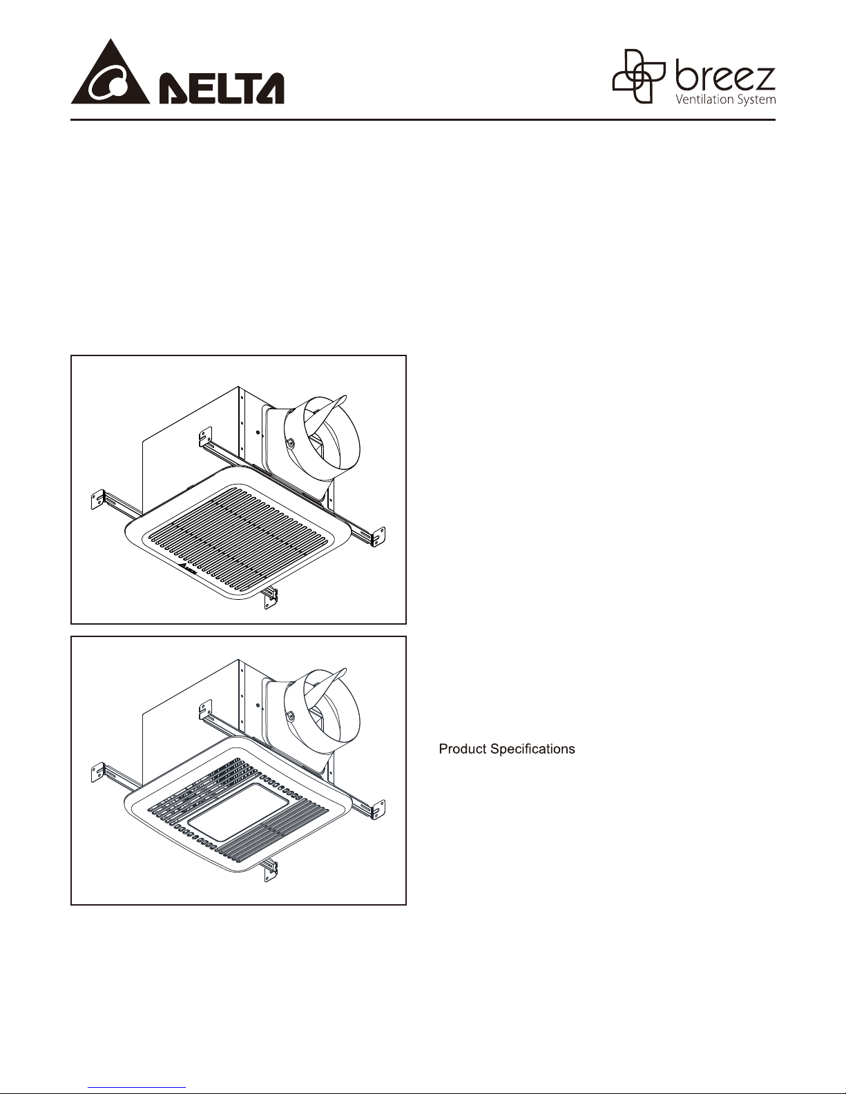
VENTILATION FAN / LED LIGHT /
LED NIGHT LIGHT
MODELS SIG80-110 / SIG80-110D / SIG80-110H / SIG80-110MH /
SIG80-110LED/ SIG80-110DLED / SIG80-110HLED / SIG80-110MHLED
TABLE OF CONTENTS
Package Contents 2
General Safety Information 3
Preparation 4
Wiring Diagrams 5
Assembly Instructions - New Construction 6
Assembly Instructions - Existing Construction 7
Grille Installation 11
READ AND SAVE THESE INSTRUCTIONS
Address: 46101 Fremont Boulevard, Fremont, CA 94538
US Toll Free Number: 1-888-979-9889
www.deltabreez.com
Operation 12
Care and Maintenance 13
Troubleshooting 14
Dimensions 15
15
Warranty 16
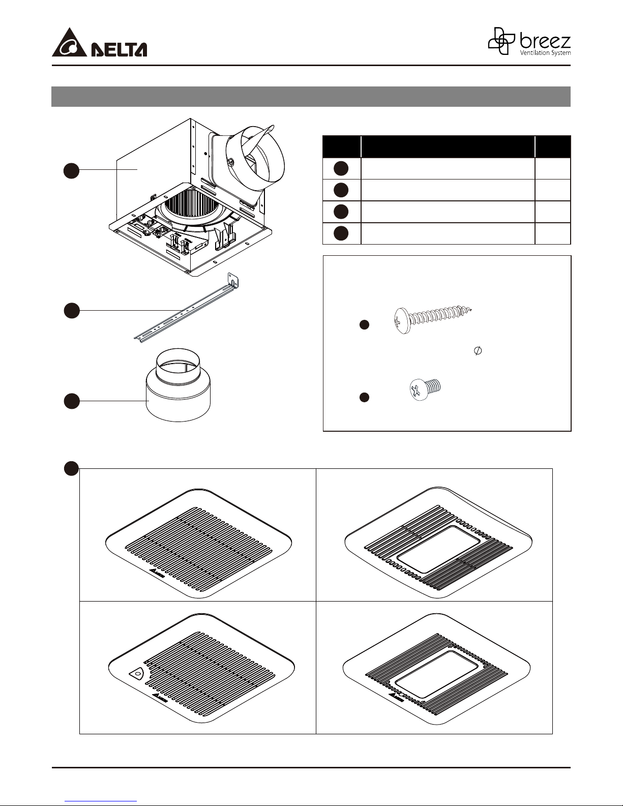
PACKAGE CONTENTS
PART DESCRIPTION QTY
1
1
2
3
4
Fan Body 1
Suspension bracket 4
6" to 4" adapter 1
Grille 1
HARDWARE CONTENTS
(Images are to scale)
2
A
Long Wood Screw ( 4 x 25mm)
3
B
Short screw (#8-32x1/4”)
X 8
X 4
4
SIG80-110
SIG80-110D
SIG80-110H
SIG80-110MH
SIG80-110LED
SIG80-110DLED
SIG80-110HLED
SIG80-110MHLED
2
GENERAL SAFETY INFORMATION
Turning angle too large Duct shrink
ydob eht raen woblEswoble ynam ooT
Body
Minimum 18 in.
READ AND SAVE THESE INSTRUCTIONS
GENERAL SAFETY INFORMATION
1. Make sure that the electric service supply voltage is AC
120V, 60Hz.
2. Follow all local electrical and safety codes, as well as
the National Electrical Code (NEC) and the Occupational
Safety and Health Act (OSH Act).
3. Always disconnect the power source before working on or
near the ventilating fan, motor or junction box.
4. Protect the power cord from sharp edges, oil, grease, hot
surfaces, chemicals or other objects.
5. Do not kink the power cord.
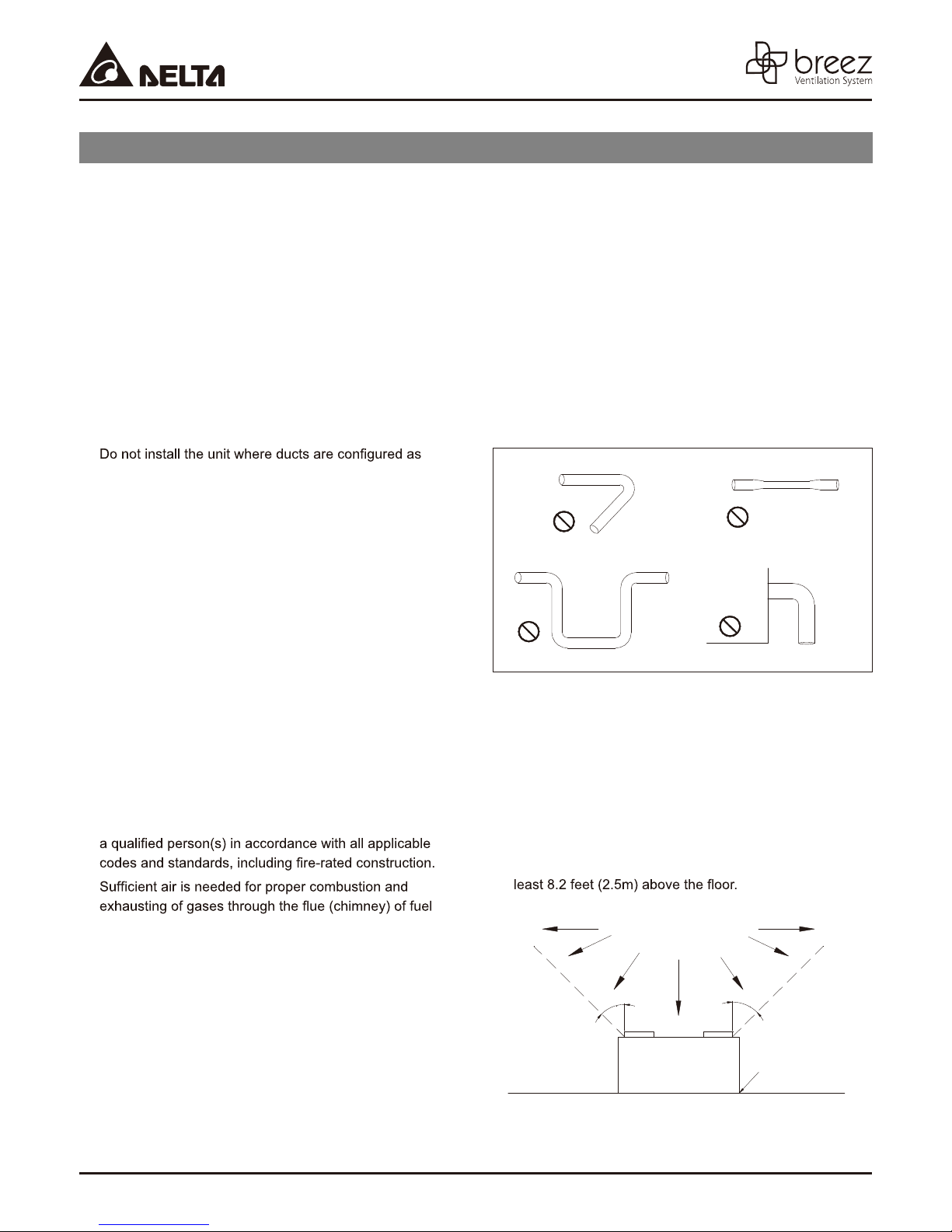
6.
shown in Fig.A.
7. Provide suction parts with proper ventilation.
8. This unit is UL Listed for use over a bathtub or shower
when installed in a GFCI protected branch circuit.
WARNING
TO REDUCE THE RISK OF FIRE, ELECTRIC SHOCK, OR
INJURY TO PERSONS, OBSERVE THE FOLLOWING:
1. Use this unit only in the manner intended by the
manufacturer. If you have questions, contact the
manufacturer.
2. Before servicing or cleaning the unit, switch the power off
at the service panel and lock the service disconnecting
means to prevent the power from being switched on
accidentally. When the service disconnecting means
cannot be locked, securely fasten a prominent warning
device, such as a tag, to the service panel.
3. Installation work and electrical wiring must be done by
4.
7. If this unit is to be installed over a tub or shower, it must
be marked as appropriate for the application and be
connected to a GFCI (Ground Fault Circuit lnterrupter) –
protected branch circuit.
8. Do not use this unit with any other solid-state control
device. Solid-state controls may cause harmonic
distortion, which can cause a motor humming noise.
9. NEVER place a switch where it can be reached from a
tub or shower.
10. Not to be installed in a ceiling thermally insulated to a
value greater than R40. (This is required for installation
in Canada only).
Turning angle too large Duct shrink
ydob eht raen woblEswoble ynam ooT
Body
Fig. A
CAUTION
1. For general ventilating use only. Do not use to exhaust
hazardous or explosive materials and vapors.
2. Not for use in cooking areas. (Fig.B)
3. This product must properly connect to the grounding
conductor of the supply circuit.
4. To reduce the risk of injury to persons, install the fan at
burning equipment to prevent backdrafting. Follow the
heating equipment manufacturer’s guideline and safety
standards such as those published by the National Fire
Protection Association (NFPA), and the American Society
for Heating Refrigeration and Air Conditioning Engineers
(ASHRAE) and local code authorities.
5. When cutting or drilling into the wall or ceiling, do not
damage electrical wiring and other hidden utilities.
6. Ducted ventilating fans must always be vented to the
outdoors.
Cooking area
Do not install above or
inside this area
4
5
5°
4
Cooking
Equipment
°
floor
Fig. B
3
PREPARATION
Tools Required for Assembly (not included): Hammer,
Flathead Screwdriver, Wire Nuts, Nails, Duct Tape,
Phillips Head Screwdriver, Utility Knife
Helpful Tools (not included): Electric Drill, Drill Bits
WARNING: Turn off electricity at breaker box
before beginning installation.
Carefully remove unit from carton.
Check area above installation location to be sure that
wiring can run to the planned location and that duct
proper ventilation.
Inspect duct work and wiring before proceeding with
installation.
Before installation, provide inspection and future
maintenance access at a location that will not
interfere with installation work.
You may need the help of a second person to install
this fan: one person on the attic side and one on the
room side.
Note: Installations may vary depending on how the
previous bath fan was installed. Supplies necessary
for the installation of your bath fan are not all included.
Howev er, most are available at your local home
improvement or hardware store.
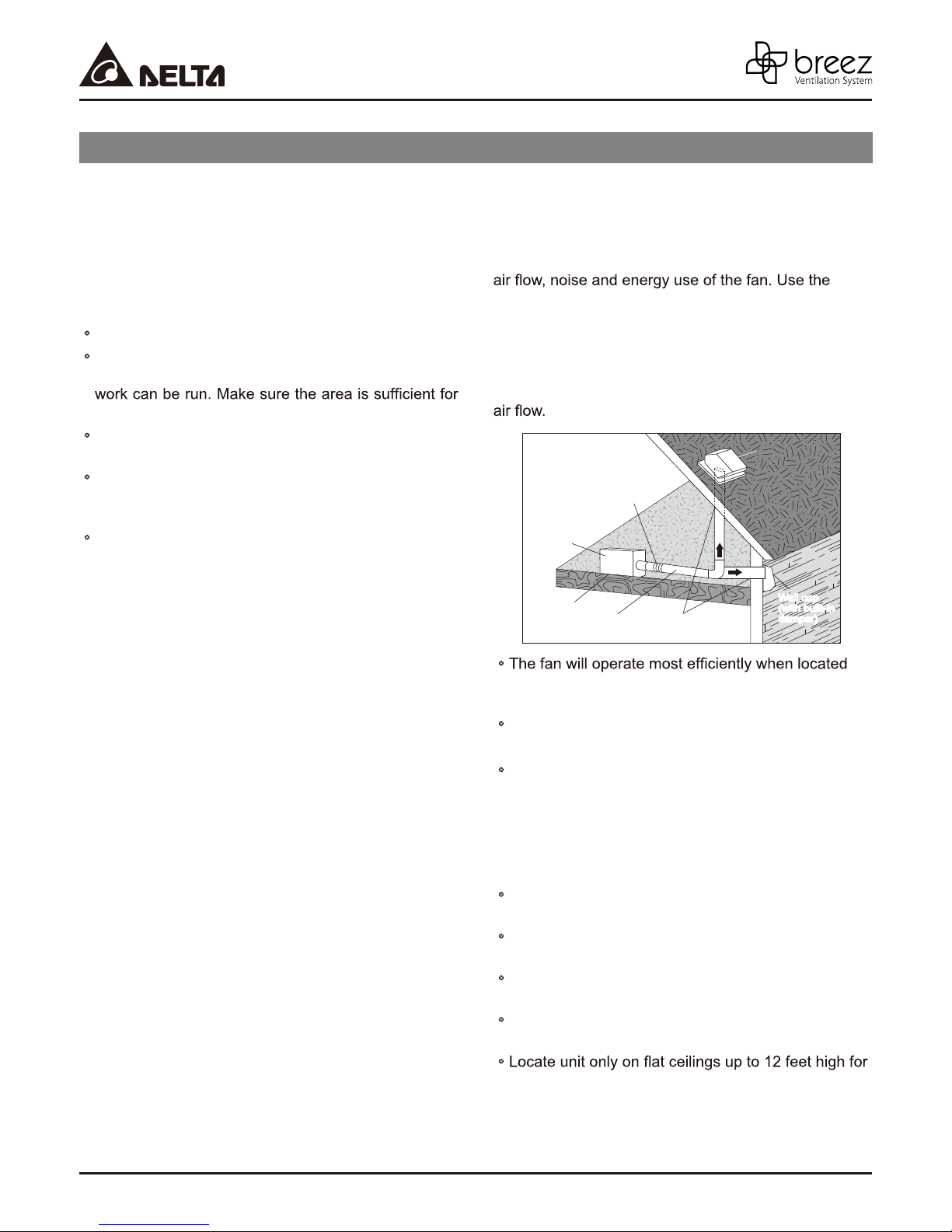
Proper insulation around the fan to minimize building
heat loss and gain. 6” circular duct is recommended
for installation. The ducting from this fan to
the outside of building has a strong effect on the
shortest, straightest duct routing possible for best
performance,and avoid installing the fan with smaller
ducts than recommended. Insulation around the ducts
can reduceenergy loss and inhibit mold growth. Fans
installed with existing ducts may not achieve their rated
Roof cap
(with built-in
Short piece of flexible
duct helps alignment
and absorbs sound
Fan housing
Seal gap
around
housing
2~3 ft straight run
before elbow
Caulk termination
to duct
damper)
or
Wall cap
Wall cap
(with built-in
(with built-in
damper)
damper)
where the shortest possible duct run and minimum
number of elbows will be needed.
Use a roof cap or wall cap that has a built-in damper
to reduce backdrafts.
External timer/dimmer switch can be used please
contact Delta Breez customer service and consult
with a licensed electrician for compatibility .
For humidity sensing models only
(SIG80-110H, SIG80-110MH,
SIG80-110HLED, SIG80-110MHLED)
or within 5 feet of the shower head.
Locate unit away from heating or cooling sources
which can affect humidity levels.
Do not locate near window. Unit may respond to the
outdoor humidity level.
Unit must be installed in ceiling to properly sense
moisture.
proper sensing.
4
)deriuqer tiucric detcetorp-ICFG( evoba tinu etacoL
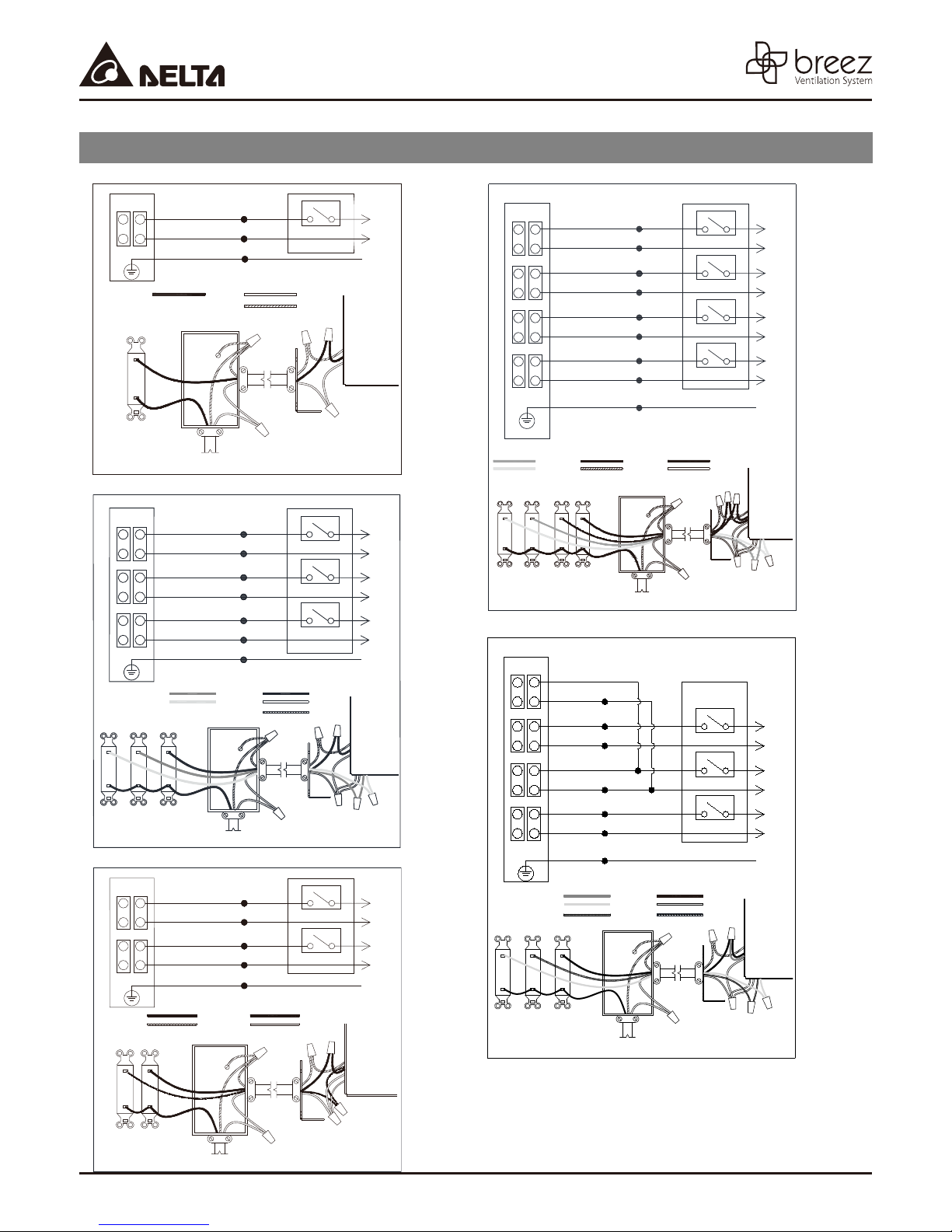
WIRING DIAGRAM
Models: SIG80-110, SIG80-110MH
JUNCTION BOX
BLACK
WHITE
GREEN
BLACK
ON/OFF SWITCH
(purchase separately)
POWER
SWITCH
Model: SIG80-110LED
JUNCTION BOX
ON/OFF SWITCH
(purchase separately)
LIGHT
NIGHT-
SWITCH
LIGHT
SWITCH
Models: SIG80-110H, SIG80-110D
JUNCTION BOX
ON/OFF SWITCH
(purchase separately)
POWER
SWITCH
SWITCH BOX
120 VAC
LINE IN
RED
SWITCH BOX
120 VAC
BLUE
(bare)
SWITCH BOX
RED
WHITE
YELLOW
WHITE
BLACK
WHITE
GREEN
YELLOW
LINE IN
BLACK
WHITE
BLUE
WHITE
GREEN
SWITCH BOX
OFF
ON
POWER SWITCH
WHITE
GROUND
(bare)
WIRING
PLATE
SWITCH BOX
OFF
ON
LIGHT SWITCH
OFF
ON
NIGHT-LIGHT SWITCH
OFF
ON
POWER SWITCH
BLACK
WHITE
GROUND
(bare)
WIRING
PLATE
SWITCH BOX
OFF
ON
POWER SWITCH
HI
MODE SWITCH
BLACK
WHITEGROUND
GRD
GRD
GRD
Models: SIG80-110HLED, SIG80-110DLED
JUNCTION BOX
L
N
RED
WHITE
YELLOW
WHITE
BLACK
WHITE
BLUE
WHITE
GREEN
RED
YELLOW
ON/OFF SWITCH
(purchase separate ly)
L
BLUE
(bare)
SWITCH BOX
N
MODE
SWITCH
POWER
SWITCH
RED
WHITE
YELLOW
WHITE
BLACK
WHITE
BLUE
WHITE
GREEN
SWITCH BOX
120 VAC
RED
YELLOW
BLUE
LINE IN
LIGHT
L
N
L
N
NIGHT-
SWITCH
LIGHT
SWITCH
Model: SIG80-110MHLED
JUNCTION BOX
L
N
ON/OFF SWITCH
(purchase separately)
L
N
MODE
NIGHTLIGHT
SWITCH
SWITCH
POWER
SWITCH
120 VAC
LINE IN
SWITCH BOX
OFF
ON
LIGHT SWITCH
OFF
ON
NIGHT-LIGHT SWITCH
OFF
ON
POWER SWITCH
HI
MODE SWITCH
BLACK
WHITEGROUND
WIRING
PLATE
SWITCH BOX
OFF
ON
NIGHT-LIGHT SWITCH
OFF
ON
POWER SWITCH
HI
MODE SWITCH
BLACK
WHITE
GROUND
(bare)
WIRING
PLATE
L
N
L
N
L
N
L
N
GRD
L
N
L
N
L
N
GRD
MODE
SWITCH
POWER
SWITCH
120 VAC
LINE IN
WIRING
PLATE
5
 Loading...