

Page 1
INSTRUCTION MANUAL
Sidekick
TM
12 Compound Miter Saw
(Model 36-235)
REVISED 6-30-00 PA R T NO. 1349865
'Delta International Machinery Corp. 1999
Page 2

2
TABLE OF CONTENTS
SAFETY RULES . . . . . . . . . . . . . . . . . . . . . . . . . . . . . . . . . . . . . . . . . . . . . . . . . . . . . . . . . . . . . . . . . . . . . . . . . . . . . . . 3
ADDITIONAL SAFETY RULES FOR COMPOUNDMITER S AW S . . . . . . . . . . . . . . . . . . . . . . . . . . . . . . . . . . . . . . . . 4
UNPACKING AND CLEANING . . . . . . . . . . . . . . . . . . . . . . . . . . . . . . . . . . . . . . . . . . . . . . . . . . . . . . . . . . . . . . . . . . . . 5
ASSEMBLY INSTRUCTIONS . . . . . . . . . . . . . . . . . . . . . . . . . . . . . . . . . . . . . . . . . . . . . . . . . . . . . . . . . . . . . . . . . . . . . 6
Moving Cuttinghead To The Up Position. . . . . . . . . . . . . . . . . . . . . . . . . . . . . . . . . . . . . . . . . . . . . . . . . . . . . . . 6
Moving Table To The 90 Degree Cut-Off Position . . . . . . . . . . . . . . . . . . . . . . . . . . . . . . . . . . . . . . . . . . . . . . . 6
Assembling Extension Table And Fence Slide . . . . . . . . . . . . . . . . . . . . . . . . . . . . . . . . . . . . . . . . . . . . . . . . . . 7
Assembling W ork Clamp. . . . . . . . . . . . . . . . . . . . . . . . . . . . . . . . . . . . . . . . . . . . . . . . . . . . . . . . . . . . . . . . . . . . 9
Assembling Dust Bag . . . . . . . . . . . . . . . . . . . . . . . . . . . . . . . . . . . . . . . . . . . . . . . . . . . . . . . . . . . . . . . . . . . . . . 9
FASTENING MACHINE TO SUPPORTING SURFACE . . . . . . . . . . . . . . . . . . . . . . . . . . . . . . . . . . . . . . . . . . . . . . . . 10
EXTENSION CORDS. . . . . . . . . . . . . . . . . . . . . . . . . . . . . . . . . . . . . . . . . . . . . . . . . . . . . . . . . . . . . . . . . . . . . . . . . . . 10
CONNECTING SAW TO POWERSOURCE
Power Connections . . . . . . . . . . . . . . . . . . . . . . . . . . . . . . . . . . . . . . . . . . . . . . . . . . . . . . . . . . . . . . . . . . . . . . . 11
Motor Specifications . . . . . . . . . . . . . . . . . . . . . . . . . . . . . . . . . . . . . . . . . . . . . . . . . . . . . . . . . . . . . . . . . . . . . . 11
Grounding Instructions . . . . . . . . . . . . . . . . . . . . . . . . . . . . . . . . . . . . . . . . . . . . . . . . . . . . . . . . . . . . . . . . . . . . 11
OPERATING CONTROLS AND ADJUSTMENTS
Starting And Stopping Machine . . . . . . . . . . . . . . . . . . . . . . . . . . . . . . . . . . . . . . . . . . . . . . . . . . . . . . . . . . . . . 12
Locking Switch In The OFF Position . . . . . . . . . . . . . . . . . . . . . . . . . . . . . . . . . . . . . . . . . . . . . . . . . . . . . . . 12
Rotating Table For Miter Cutting . . . . . . . . . . . . . . . . . . . . . . . . . . . . . . . . . . . . . . . . . . . . . . . . . . . . . . . . . . . . 12
Adjusting Clamping Action Of Table Locking Mechanism . . . . . . . . . . . . . . . . . . . . . . . . . . . . . . . . . . . . . . . 13
Adjusting Sliding Fit Between Movable Table And Base. . . . . . . . . . . . . . . . . . . . . . . . . . . . . . . . . . . . . . . . . 14
Adjusting Fence 90 Degrees To Blade . . . . . . . . . . . . . . . . . . . . . . . . . . . . . . . . . . . . . . . . . . . . . . . . . . . . . . . . 14
Table Hazard Area . . . . . . . . . . . . . . . . . . . . . . . . . . . . . . . . . . . . . . . . . . . . . . . . . . . . . . . . . . . . . . . . . . . . . . . . 15
W ork Clamp Operation . . . . . . . . . . . . . . . . . . . . . . . . . . . . . . . . . . . . . . . . . . . . . . . . . . . . . . . . . . . . . . . . . . . . 15
T ilting Cuttinghead For Bevel Cutting . . . . . . . . . . . . . . . . . . . . . . . . . . . . . . . . . . . . . . . . . . . . . . . . . . . . . . . . 16
Adjusting Sliding Fence . . . . . . . . . . . . . . . . . . . . . . . . . . . . . . . . . . . . . . . . . . . . . . . . . . . . . . . . . . . . . . . . . . . 17
Adjusting Chip Deflector . . . . . . . . . . . . . . . . . . . . . . . . . . . . . . . . . . . . . . . . . . . . . . . . . . . . . . . . . . . . . . . . . . . 17
Adjusting 90 And 45 Degree Bevel Positive Stops. . . . . . . . . . . . . . . . . . . . . . . . . . . . . . . . . . . . . . . . . . . . . . 18
Adjusting Sliding Fit Between Trunnion And Bevel Bracket . . . . . . . . . . . . . . . . . . . . . . . . . . . . . . . . . . . . . . 19
Adjusting Tension Of Cuttinghead Return S pring . . . . . . . . . . . . . . . . . . . . . . . . . . . . . . . . . . . . . . . . . . . . . . 20
Adjusting Sliding Fit Between Cuttinghead Arm And Trunnion . . . . . . . . . . . . . . . . . . . . . . . . . . . . . . . . . . . 20
Adjusting Downward Travel Of Saw Blade . . . . . . . . . . . . . . . . . . . . . . . . . . . . . . . . . . . . . . . . . . . . . . . . . . . . 20
Tool Storage . . . . . . . . . . . . . . . . . . . . . . . . . . . . . . . . . . . . . . . . . . . . . . . . . . . . . . . . . . . . . . . . . . . . . . . . . . . . . 21
Adjusting Blade Guard . . . . . . . . . . . . . . . . . . . . . . . . . . . . . . . . . . . . . . . . . . . . . . . . . . . . . . . . . . . . . . . . . . . . 21
TYPICAL OPERATIONS A N D HELPFUL HINTS . . . . . . . . . . . . . . . . . . . . . . . . . . . . . . . . . . . . . . . . . . . . . . . . . . . . . 22
Auxiliary Wood Fence . . . . . . . . . . . . . . . . . . . . . . . . . . . . . . . . . . . . . . . . . . . . . . . . . . . . . . . . . . . . . . . . . . . . . 23
Cutting Aluminum . . . . . . . . . . . . . . . . . . . . . . . . . . . . . . . . . . . . . . . . . . . . . . . . . . . . . . . . . . . . . . . . . . . . . . . . 23
Cutting Bowed Material . . . . . . . . . . . . . . . . . . . . . . . . . . . . . . . . . . . . . . . . . . . . . . . . . . . . . . . . . . . . . . . . . . . . 24
Constructing Work Support Extensions . . . . . . . . . . . . . . . . . . . . . . . . . . . . . . . . . . . . . . . . . . . . . . . . . . . . . . 24
Cutting Crown Moulding . . . . . . . . . . . . . . . . . . . . . . . . . . . . . . . . . . . . . . . . . . . . . . . . . . . . . . . . . . . . . . . . . . . 25
MAINTENANCE
Changing The Blade . . . . . . . . . . . . . . . . . . . . . . . . . . . . . . . . . . . . . . . . . . . . . . . . . . . . . . . . . . . . . . . . . . . . . . 26
Brush Inspection And R eplacement . . . . . . . . . . . . . . . . . . . . . . . . . . . . . . . . . . . . . . . . . . . . . . . . . . . . . . . . . 27
W ARRANTY. . . . . . . . . . . . . . . . . . . . . . . . . . . . . . . . . . . . . . . . . . . . . . . . . . . . . . . . . . . . . . . . . . . . . . . . . . . . . . . . . . 28
Page 3

3
SAFETY RULES
W oodworking can be dangerous if safe and proper operating procedures are not followed. As with all machinery, there are cert ain
hazards involved with the operation of the product. Using the machine with respect and caution will considerably lessen the possi bility of personal injury . However, if normal safety precautions are overlooked or ignored, personal injury to the operator may result.
Safety equipment such as guards, push sticks, hold-downs, featherboards, goggles, dust masks and hearing protection can reduce
your potential for injury . But even the best guard won t make up for poor judgment, carelessness or inattention. Always use common
sense and exercise caution in the workshop. If a procedure feels dangerous, don t try it. Figure out an alternative procedure that feels
safer . REMEMBER: Your personal safety is your responsibility.
This machine was designed for cert ain applications only . Delt a Machinery strongly recommends that this machine not be modified
and/or used for any application other than that for which it was designed. If you have any questions relative to a p articular applica tion, DO N O T use the machine until you have first cont acted Delt a to determine if it can or should be performed on the product.
Technical Service Manager
Delt a International Machinery Corp.
4825 Highway 45 North
P.O. Box 2468
Jackson, TN 38302-2468
(IN CANADA: 505 SOUTHGATE DRIVE, GUELPH, ONTARIO N1H 6M7)
W ARNING: FAILURE TO FOLLOW THESE RULES
M AY RESULT IN SERIOUS PERSONAL INJURY
1. FORYOURO W N SAFETY, READ INSTRUCTION MANUAL
BEFORE OPERATING T H E TO O L. Learn the tool s application and
limit ations as well as the specific hazards peculiar to it.
2. KEEP GUARDSIN PLACE and in working order.
3. ALW AYS WEAREYEPROTECTION.
4. GROUND ALL TOOLS. If tool is equipped with three-prong
plug, it should be plugged into a three-hole electrical recept acle. If
an adapter is used to accommodate a two-prong recept acle, the
adapter lug must be att ached to a known ground. Never remove the
third prong.
5. REMOVE ADJUSTING KEYS A ND WRENCHES. Form habit
of checking to see that keys and adjusting wrenches are removed
from tool before turning it on.
6. KEEP WORKAREACLEAN. Cluttered areas and benches
invite accident s.
7. DON T USE IN DANGEROUS ENVIRONMENT. Don t use
power tools in damp or wet locations, or expose them to rain. Keep
work area well-lighted.
8. KEEP CHILDREN AND VISITO R S A W A Y . All children and
visitors should be kept a safe dist ance from work area.
9. MAKE WORKSHOP CHILDPROOF with p adlocks, master
switches, or by removing st arter keys.
10. D O N T F O R C E T O O L . It will do the job better and be safer at
the rate for which it was designed.
11. USE RIGHT TOO L. Don t force tool or att achment to do a job
for which it was not designed.
12. WEAR PROPER APPAREL. No loose clothing, gloves, neck ties, rings, bracelet s, or other jewelry to get caught in moving p arts.
Nonslip footwear is recommended. Wear protective hair covering to
cont ain long hair .
13. ALW AYS USE SAFETY GLASSES.W ear safety glasses.
Everyday eyeglasses only have impact resist ant lenses; they are not
safety glasses. Also use face or dust mask if cutting operation is dusty.
14. SECURE WORK. Use clamp s or a vise to hold work when
practical. It s safer than using your hand and frees both hands to
operate tool.
15. DON T OVERREACH. Keep proper footing and balance at all
times.
16. MAINTAIN TOOLSIN TO P CONDITION. Keep tools sharp
and clean for best and safest performance. Follow instructions for
lubricating and changing accessories.
17. DISCONNECT TOOLS before servicing and when changing
accessories such as blades, bit s, cutters, etc.
18. USERECOMMENDEDACCESSORIES. The use of acces sories and att achments not recommended by Delt a may cause
hazards or risk of injury to persons.
19. REDUCETHE RISK O F UNINTENTIONAL STARTING. Make
sure switch is in OFF position before plugging in power cord.
20. NEVER STAN D O N TOOL. Serious injury could occur if the
tool is tipped or if the cutting tool is accident ally cont acted.
21. CHECK DAMAGEDPARTS. Before further use of the tool, a
guard or other p art that is damaged should be carefully checked to
ensure that it will operate properly and perform it s intended function
check for alignment of moving p art s, binding of moving p arts,
breakage of p art s, mounting, and any other conditions that may
affect it s operation. A guard or other p art that is damaged should be
properly rep aired or replaced.
22. DIRECTION O F FEED. Feed work into a blade or cutter
against the direction of rot ation of the blade or cutter only .
23. NEVER LEAVE TOOL RUNNING UNATTENDED. TURN
POWEROFF. Dont leave tool until it comes to a complete stop.
24. DRUGS, ALCOHOL, MEDICATION. Do not operate tool while
under the influence of drugs, alcohol or any medication.
25. MAKE SURE TOOL IS DISCONNECTED FROM POWER
SUPPLY while motor is being mounted, connected or reconnected.
26. W ARNING: The dust generated by certain woods and wood
product s can be injurious to your health. Always operate machinery
in well ventilated areas and provide for proper dust removal. U s e
wood dust collection systems whenever possible.
27. W ARNING: SOME DUST CREATED BY POWER SANDING,
SAWING, GRINDING, DRILLING, AND OTHER CONSTRUCTION
ACTIVITIES cont ains chemicals known to cause cancer, birth
defect s or other reproductive harm. Some examples of these chem icals are: lead from lead-based p aint s; cryst alline silica from bricks
and cement and other masonry products, and arsenic and chromi um from chemically-treated lumber. Y our risk from these exposures
varies, depending on how of ten you do this type of work. T o reduce
your exposure to these chemicals: work in a well ventilated area,
and work with approved safety equipment, such as those dust
masks that are specially designed to filter out microscopic p articles.
SAVE THESE INSTRUCTIONS.
Page 4

4
ADDITIONAL SAFETY RULES FOR
COMPOUND MITER S AW S
1. W ARNING: U S E O NLY CROSS-CUTTING SAW
BLADES. D O NOT USE BLADES WITH DEEP GULLETS A S THEY CAN DEFLECT AN D CONTACT
GUARD.
2. W ARNING: Do not operate the miter saw until it is
completely assembled and inst alled according to the
instructions.
3.IF Y O U A R E N O T thoroughly familiar with the oper ation of compound miter saws, obt ain advice from your
supervisor, instructor or other qualified person.
4. A LW A Y S hold the work firmly against the fence and
table. D O N O T perform any operation freehand.
5. W ARNING: ALW AY S keep hands out of p ath of saw
blade. If the workpiece you are cutting would cause your
hand to be inside the t able hazard area (see section
TABLE HAZARD AREA ), the workpiece should be
clamped in place before making cut.
6. B E SUREblade is sharp, runs freely and is free of
vibration.
7. ALLOW the motor to come up to full speed before
st arting cut.
8. KEEP motor air slot s clean and free of chip s.
9. ALWAYSMAKE SURE rot ating t able is tight before
cutting, even if the t able is positioned in one of the
positive stop s.
10. BE SURE blade and flanges are clean and that arbor
screw is tightened securely.
11. U S E only blade flanges specified for your saw .
12. NEVER use blades larger or smaller in diameter than
recommended. Recommended size of blade is 12 in
diameter.
13. NEVER apply lubricant s to the blade when it is running.
14. A L W A Y S check the blade for cracks or damage
before operation. Replace cracked or damaged blade
immediately.
15. NEVER use blades recommended for operation at
less than 4800 RPM.
16. U S E the blade guard at all times.
17. A L W A Y S keep the lower blade guard in place and
operating properly.
18. NEVER reach around or behind saw blade.
19. MAKE SURE blade is not cont acting workpiece before switch is turned on.
20. NEVER lock the switch in the ON position.
21. IMPORTAN T:Af ter completing cut, release power
switch and wait for coasting blade to stop before return ing saw to raised position.
22. TURN OFF S AW and M A K E SURE blade has come
to a complete stop before removing or securing work piece, changing workpiece angle or changing the angle
of the blade.
23. D O N O T remove jammed or cut-off pieces until
blade has stopped.
24. NEVER cut ferrous met als or masonry.
25. NEVER recut small pieces.
26. PROVIDE adequate support to the sides of the saw
table for long workpieces.
27. NEVER use the miter saw in an area with flammable
liquids or gases.
28. NEVER use solvent s to clean plastic p art s. Solvent s
could possibly dissolve or otherwise damage the material .
Only a sof t, damp cloth should be used to clean plastic
parts.
29. DISCONNECT saw from power source before ser vicing or changing blades.
30. DISCONNECT saw from power source and clean
the machine before leaving it.
31. MAKE SURE the work area is cleaned before leaving
the machine.
32. SHOULD any part of your miter saw be missing,
damaged or fail in any way, or any electrical component
fail to perform properly , shut of f switch and remove plug
from power supply outlet. Replace missing, damaged or
failed p art s before resuming operation.
33. ADDITIONAL INFORMATION regarding the safe
and proper operation of this product is available from the
National Safety Council, 1121 Spring Lake Drive, It asca,
IL 60143-3201, in the Accident Prevention Manual for
Industrial Operation and also in the Safety Dat a Sheet s
provided by the NSC. Please also refer to the American
National Standard Institute ANSI 01.1 Safety Requirem e n t s for W oodworking Machinery and the U.S. Dep artment of Labor OSHA 1910.213 Regulations.
34. S AVE THESE INSTRUCTIONS. Refer to them fre quently and use them to instruct others.
Page 5
5
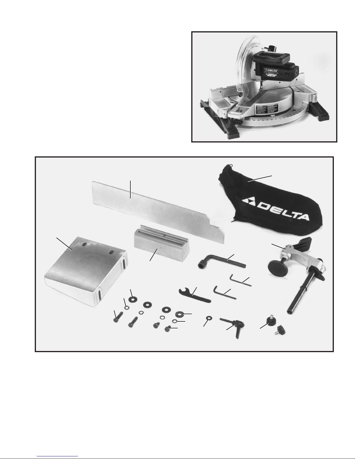
UNPACKING A ND CLEANING
Fig. 2
Your new compound miter saw is shipped complete in
one carton. Carefully unp ack the machine and all loose
items from the carton. IMPORTANT:D O NO T LIFT T H E
MITER S AW B Y TH E SWITCH HANDLE O R TABLE
CONTROL HANDLE AS THIS M AY CAUSE MISALIGNMENT. A LW A Y S LIFT T H E MACHINE B Y THE
BASE. Remove the protective coating from all unp ainted
parts. This coating may be removed with a sof t cloth
moistened with kerosene (do not use acetone, gasoline,
or lacquer thinner for this purpose). Figure 2 illustrates
the saw removed from the carton. Note that the machine
is shipped with the cuttinghead locked in the down
position and the t able rot ated to the 45 degree lef t miter
position. Figure 3 illustrates the loose items supplied with
your machine.
1 -Extension t able
2 -Fence slide
3 -Fence slide support
4 -Dust bag
5 - W ork clamp
6 -Arbor and fence wrench
7 -1/8 hex wrench
8 -5/32 hex wrench
9 -Open end wrench
10 -Lock knobs for work clamp (2)
11 - Lock handle for slide fence
12 -1/4 flat washer
Fig. 3
13 -5/16 flat washer (2)
14 -5/16 lock washer (2)
15 -5/16-18 x 1/2 long hex head screw (2)
16 -5/16 flat washer (2)
17 -5/16 lock washer (2)
18 - 5/16-18 x 1-1/4 long hex head screws (2)
17
16
18
13
14
15
12
9
11
10
8
7
6
5
3
2
1
4
Page 6
6
ASSEMBLY INSTRUCTIONS
W ARNING: F O R YOUR O W N SAFETY, DO NOT CONNECT THE MITER S AW TO THE
POWER SOURCE UNTIL THE MACHIN E IS COMPLETELY ASSEMBLED AN D YOU
HAVE READAND UNDERSTO O D THE ENTIRE OWNERSMANUAL.
Fig. 4
Fig. 5
Fig. 6
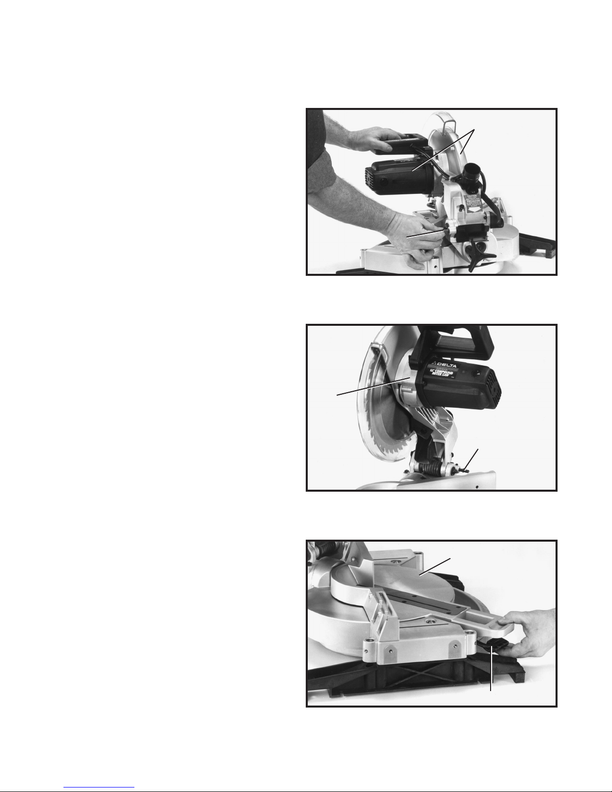
MOVING CUTTINGHEAD
TO THE UP POSITION
1. Pull out cuttinghead lockpin (A) Fig. 4, and move the
cuttinghead (B) to the up position.
2. Fig. 5, illustrates the lockpin (A) pulled out and the
cuttinghead (B) in the up position.
MOVING TABLE TO
THE 90 DEGREE
C U T-OFF POSITION
1. Depress table lock lever (A) Fig. 6, and rot ate t able (B)
to the 90 degree straight cut-of f position. Then release
lock lever (A).
B
A
B
A
B
A
Page 7
7
Fig. 7
Fig. 7A
Fig. 7B
Fig. 7C
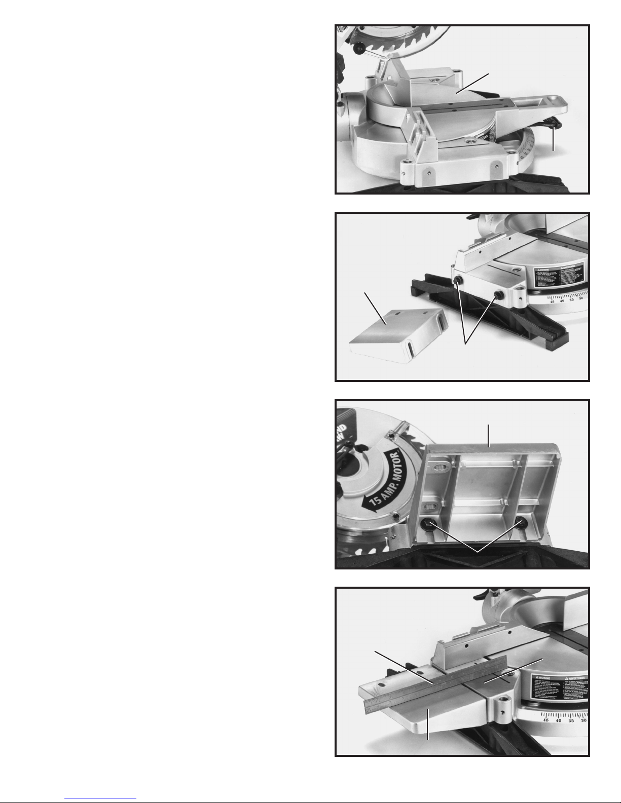
2. Fig. 7, illustrates the t able (B) in the 90 degree
straight cut-of f position. NOTE: Table lock lever (A) must
be depressed when rotating t able. When lock lever (A) is
not depressed, the t able is in the locked position and
cannot be moved.
3. For proper operation and adjustment of the t able, refer
to sections, R O T A TING TABLE FOR MITER CUTTING,
ADJUSTING CLAMPING ACTION O F TABLE LOCKING
MECHANISM and ADJUSTING SLIDING FIT BETWEEN
M O VABLE TABLE AND BASE.
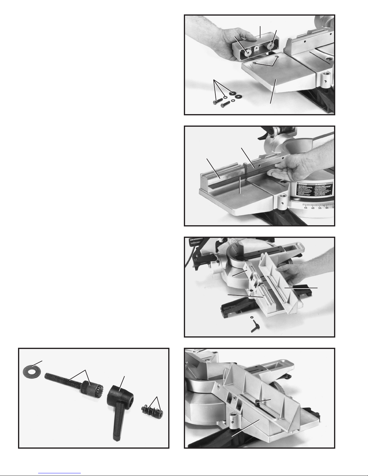
ASSEMBLING EXTENSION
TABLE AND FENCE SLIDE
1. Place 5/16 lockwasher and 5/16 flat washer on
each 1/2 long hex head screw (A) Fig. 7A, and thread
the two screws (A) into the two threaded holes on lef t
side of saw t able, as shown. NOTE: Only thread the
screws a few threads into the holes at this time.
2. Assemble the table extension (B) Figs. 7A and 7B, to
lef t side of saw t able making sure groove of table exten sion (B) is inside flat washers as shown in Fig. 7B.
3. Using a straight edge (C) Fig. 7C, make cert ain
extension t able (B) is level with saw t able (D) as shown,
and tighten the two screws (A) Fig. 7B.
B
A
B
A
B
A
B
C
D
Page 8
8
4. Assemble the fence slide support (E) Fig. 7D, to the
extension t able (B) using the two 1-1/4 long hex head
screws, 5/16 lockwashers and 5/16 flat washers (F).
Bring screws up through the two holes (G) in t able exten sion and thread them into the two threaded holes (H) on
bottom of fence slide support. NOTE: Do not completely
tighten screws at this time.
Fig. 7D
Fig. 7E
Fig. 7F
Fig. 7HFig. 7G
5. Using a straight edge (C) Fig. 7E, make cert ain
fence slide support (E) is level with saw fence (J) as
shown, and tighten the two screws that were assembled
in STEP 4.
6. Position the fence slide (K) Fig. 7F , in position on top
of saw fence (J) and fence slide support (E). Slide fence
slide (K) back and forth several times to check alignment
of fence slide support (E) and make final adjustment to
fence slide support if necessary.
7. Remove screw and spring (L) Fig. 7G, and lock
handle (M) from locking stud (N) as shown.
8. Place 1/4 flat washer (O) Fig. 7G, onto locking stud
(N) and insert locking stud (N) Fig. 7H, through slot in
fence slide and thread locking stud into threaded hole in
fence slide support (E) as shown.
H
F
B
G
E
H
J
E
J
E
K
O
N
M
L
N
E
Page 9
9
Fig. 7J
Fig. 8
Fig. 9
Fig. 10
9. Position lock handle (M) Fig. 7J, on locking stud and
replace screw and spring (L) that were removed in STEP 7.
NOTE: Lock handle (M) is spring-loaded and can be repositioned by lif ting up on handle and repositioning it on
stud located underneath handle.
ASSEMBLING WORK CLAMP
1. The st andard equipment work clamp can be assembled
to any one of the three holes (A) Fig. 8, provided on the
base of the machine, as follows:
2. Thread lock knob (B) Fig. 9, into threaded hole on
side of hole to be used and insert post (C) of work clamp
down through hole as far as possible. Then tighten lock
knob (B). An additional lock knob (B) is supplied and can
be threaded into one of the other three holes. W e sugges t
having the two lock knobs, one of which is shown at (B),
threaded into the two most commonly used holes where
the work clamp will be used.
3. For proper operation and adjustment of the work
clamp, refer to section WORKCLAMP OPERATION .
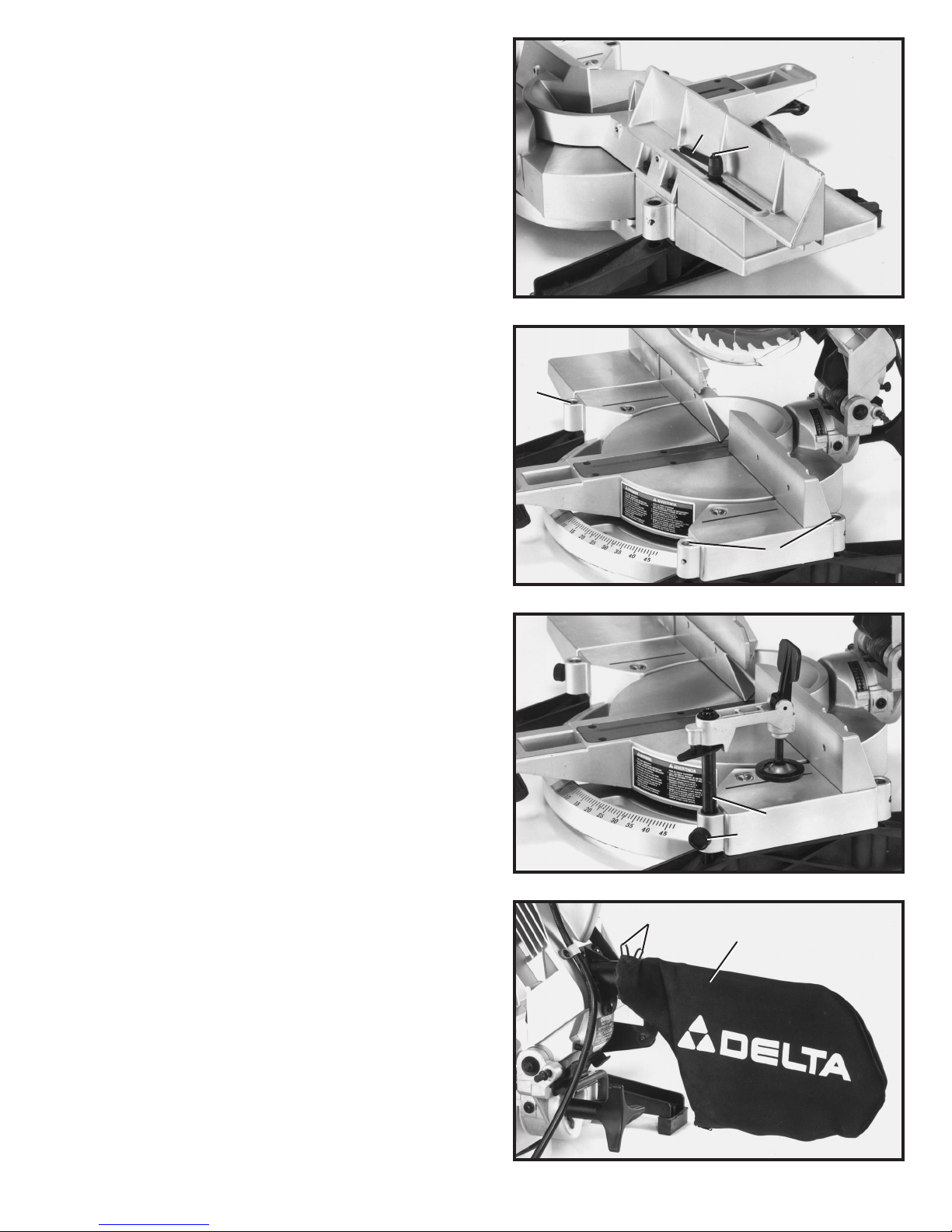
ASSEMBLING DUST BAG
1. Depress spring clip s (A) Fig. 10, of dust bag (B) and clip
dust bag (B) onto end of dust chute, as shown.
L
M
A
A
C
B
A
B
Page 10

10
Fig. 12
EXTENSION CORDS
Use proper extension cords. Make sure your extension
cord is in good condition and is a 3-wire extension cord
which has a 3-prong grounding type plug and a 3-pole
recept acle which will accept the tool s plug. When using
an extension cord, be sure to use one heavy enough to
carry the current of the saw . An undersized cord will
cause a drop in line volt age resulting in loss of power and
overheating. Fig. 12, shows the correct gage to use depending on cord length and volt age. If in doubt, use the
next heavier gage. The smaller the gage number, the
heavier the cord.
TO TAL LENGTH O F
CORDIN FEET
0 - 25
26 - 50
51 - 100
101 - 150
GAGEOFEXTENSION
CORDTO USE
14 A W G
12 A W G
Not recommended
Not recommended
FASTENING MACHINE TO SUPPORTING SURFA C E
Before operating your compound miter saw, make sure it is firmly mounted to a workbench or
other supporting surface. Four holes (A) Fig. 1 1, are provided for fastening the saw to a support ing surface.
When frequently moving the saw from place to place, we suggest that the saw be mounted to a
3/4 piece of plywood. The saw can then be easily moved from place to place and the plywood
clamped to the supporting surface using C clamps.
Fig. 1 1
A
A
A
A
Page 11

11
CONNECTING SAW TO POWERSOURCE
POWERCONNECTIONS
A s e p arate electrical circuit should be used for your tools. This circuit should not be less than #12 wire and
should be protected with a 20 Amp time lag fuse. If an extension cord is used, use only 3-wire extension
cords which have 3-prong grounding type plugs and 3-pole recept acles which accept the tool s plug.
Before connecting the motor to the power line, make sure the switch is in the OFF position and be sure
that the electric current is of the same characteristics as indicated on the tool. All line connections should
make good contact. Running on low volt age will damage the motor .
M O TO R SPECIFICATIONS
Y our saw is wired for 1 10-120 volt s, 60 HZ alternating current. Before connecting the saw to the power
source, make sure the switch is in the OFF position. The motor provides a no-load speed of 3600 RPM.
GROUNDING INSTRUCTIONS
CAUTION: THIS TO O L MUSTBE GROUNDEDWHILE IN USE
TO PROTECT THE OPERATO R FROM ELECTRIC SHOCK.
Fig. 13 Fig. 14
GROUNDED OUTLET B OX
CURRENT
CARRYING
PRONGS
GROUNDING BLADE
IS LONGEST O F THE 3 BLADES
GROUNDED OUTLET B OX
GROUNDING MEANS
ADAPTER
CAUTION: IN ALL CASES, MAKE CERTAIN THE RECEPTACLE IN QUESTION IS PROPERLY GROUNDED.
IF Y O U A R E N O T SURE, H AVE A CERTIFIED ELECTRICIAN CHECK THERECEPTACLE.
This tool is intended for use on a circuit that has an outlet
and a plug that looks like the one shown in Fig. 13. A
temporary adapter, which looks like the adapter illustrated
in Fig. 14, may be used to connect this plug to a 2-pole
recept acle, as shown in Fig. 14, if a properly grounded
outlet is not available. The temporary adapter should be
used only until a properly grounded outlet can be inst alled by a qualified electrician. THIS ADAPTER IS
N O T APPLICABLE IN CANADA. The green-colored
rigid ear , lug, and the like, extending from the adapter
must be connected to a permanent ground, such as a
properly grounded outlet box, as shown in Fig. 14.
In the event of a malfunction or breakdown, grounding
provides a p ath of least resist ance for electric
current to reduce the risk of electric shock. The motor is
equipped with an electric cord having an equipmentgrounding conductor and a grounding plug. The plug
must be plugged into a matching outlet that is properly
inst alled and grounded in accordance with all local codes
and ordinances.
Do not modify the plug provided - if it will not fit the outlet,
have the proper outlet inst alled by a qualified electrician.
Improper connection of the equipment-grounding conduc tor can result in risk of electric shock. The conductor with
insulation having an outer surface that is green with or
without yellow stripes is the equipment-grounding conduc tor. If rep air or replacement of the electric cord or plug is
necessary, do not connect the equipment grounding con ductor to a live terminal.
Check with a qualified electrician or service personnel if
the grounding instructions are not completely under stood, or if in doubt as to whether the tool is properly
grounded.
Use only 3-wire extension cords that have 3-prong
grounding type plugs and 3-hole recept acles that accept
the tool s plug, as shown in Fig. 13.
R e p air or replace damaged or worn cord immediately.
Page 12

12
OPERATING CONTROLS A N D ADJUSTMENTS
Fig. 15
Fig. 16
Fig. 17
STARTING A N D
STOPPING MACHINE
To st art the machine, depress switch trigger (A) Fig. 15.
To stop the machine, release the switch trigger .
This saw is equipped with an automatic electric blade
brake. As soon as the switch trigger (A) Fig. 15, is released, the electric brake is activated and stop s the
blade in seconds.
DANGER: A TURNING SAW BLADECAN BE DANGEROUS. AFTER COMPLETING CUT, RELEASE SWITCH
TRIGGER (A) FIG. 15, T O ACTIVATE BLADE BRAKE.
KEEP CUTTINGHEAD DOWN UNTIL BLADE HAS COME
TO A COMPLETE STO P.
W ARNING: TH E TORQUE DEVELOPED DURING BRAKING M AY LOOSEN THE ARBOR SCREW. THE ARBOR
SCREWSHOULD BE CHECKED PERIODICALLY A N D
TIGHTENED IF NECESSARY.
LOCKING SWITCH
IN THE OFF POSITION
IMPORTANT:W e suggest that when the miter saw is not
in use, the switch be locked in the OFF position using a
p adlock (B), as shown in Fig. 16. A vailable as an acces sory from Delt a is the 50-325 p adlock, shown at (B).
R O TA TING TABLE
FOR MITER CUTTING
1. Your compound miter saw will cut any angle from a
straight 90 degree cut to 47 degrees right and lef t. Simply
depress t able lock lever (A) Fig. 17, and rot ate the t able
to the desired angle. Then release t able lock lever (A).
2. IMPORTANT:Table lock lever (A) Fig. 17, must be
depressed when rotating the t able. When lock lever (A)
is not depressed, the t able is in the locked position.
A
B
A
Page 13

13
3. The compound miter saw is equipped with spring-loaded positive stops at the 90 degree straight cut-off
position and at the 15, 22.5, 31.62 and 45 degrees right and lef t miter positions. T h ese s p r ing-l o a ded
positive stop s can be felt as you are rot ating the t able. NOTE: The 31.62 degree right and lef t miter positive
stops are used when cutting crown moulding as explained later in this manual. A large scale (B) Fig. 18, and
cursor (C) is provided for intermediate angles.
4. The center line (C) Fig. 18, on the cursor indicates the actual angle of cut. Each line on the scale (B)
represent s one degree. In ef fect, when the center line (C) is moved from one line to the next on the scale,
the angle of cut is changed by one degree.
5. The pointer is provided with two additional lines (D) and (E) Fig. 18. This allows you to move the control
arm exactly 1/2 degree. For example, assume the center line (C) is pointing to the 10 degree mark on the
scale, as shown, and you want to change the angle of cut 1/2 degree to the right. Move the control arm until
the right line (E) lines up with the next line on the scale. The angle of cut will then be changed 1/2 degree to
the right. If you were changing the angle of cut 1/2 degree to the lef t, use the lef t line (D) in the same mann er.
Fig. 19
When rotating the t able, the t able locking lever must be
depressed. When the locking lever is not depressed, the
table should be in the locked position. If af ter a long period
of time the clamping action of the t able locking mechanism needs adjusted, proceed as follows:
1. Loosen locknut (A) Fig. 19, using open end wrench
supplied. T urn screw (B) with allen wrench supplied. T urn
screw clockwise to increase or counterclockwise to decrease clamping action of locking lever. IMPORTA NT:
Af ter adjustment is completed tighten locknut (A),
just enough to t ake all play out of the handle assembly.
Tightening locknut (A) too much will defeat the
purpose of the adjustment.
ADJUSTING CLAMPING ACTION OF
TABLE LOCKING MECHANISM
Fig. 18
D
E
C
B
B
A
Page 14

14
Fig. 20
ADJUSTING SLIDING FIT
BETWEEN MOVABLE
TABLE AND BASE
If it ever becomes necessary to adjust the sliding fit
between the movable t able and the base, turn nut (A)
Fig. 20, clockwise to increase or counterclockwise to
decrease the sliding fit. This adjustment should not be
too tight that it restrict s the rot ating movement of the
table or too loose that it af fect s the accuracy of the saw .
Fig. 21
Fig. 22
ADJUSTING FENCE 90 DEGREES TO BLADE
IMPORTANT:BEFORE MAKING THIS ADJUSTMENT MAKE CERTAIN THE BLADE IS SET
AT 90 DEGREES TO T HE TABLE. SEE SECTION ADJUSTING 90 A N D 45 DEGREE BEVEL
POSITIVE STOPS.
1. DISCONNECT THE S AW FROMTHE POWER
SOURCE.
2. Rot ate the movable t able so that the blade is 90
degrees to the fence and the spring-loaded positive stop
for the 0 degree mark on the scale is engaged.
3. Using a square (A) Fig. 21, place one end of the
square against the front of the fence (B) and the other
end against the blade (C), with the blade in the down
position, as shown. Check to see if the fence is 90
degrees to the blade.
4. If an adjustment is necessary, the fence (B) Fig. 21,
can be adjusted by loosening the four screws, two of
which are shown at (D), that att ach the fence to the base,
using wrench (E) supplied. Adjust the fence (B) as
required and tighten the four screws (D).
5.Af ter you are sure the fence is 90 degrees to the
blade, adjust the cursor (F) Fig. 22, so the pointer is
aligned with the 0 degree mark on the scale by loosen ing two screws (G), adjusting cursor (F) and tightening
screws (G).
A
A
B
E
D
C
G
F
Page 15

15
Fig. 23
Fig. 24
Fig. 25
Fig. 26
TABLE HAZARD AREA
W ARNING: THE AREA INSIDE T H E T W O R E D LINES
(A) F IG. 23, ON T H E TABLE IS DESIGNATED AS A H AZARD
ZONE. NEVER PLACE YOURHANDS INSIDE THIS
AREA
WHILE THE TO OL IS BEING OPERATED.
WORK CLAMP OPERATION
1. The height of the work clamp (A) Fig. 24, can be
adjusted by loosening lock knob (B) and moving post (C)
up or down, or depressing lock lever (D) and sliding clamp
body (E) up or down. Af ter height of clamp (A) is adjusted,
tighten lock knob (B) and/or release lock lever (D).
2. During operation, lower clamp (A) Fig. 25, by depressing lock lever (D), until the bottom of the clamp (A)
lightly cont act s top of workpiece (F). IMPORTANT:
When lowering clamp (A) make certain cam lever (G)
is in the up position as shown.
3. For final clamping of the workpiece (F) Fig. 26,
against the t able, move cam lever (G) to the rear , as
shown. Af ter cut is completed, lif t lever (G). This will raise
clamp (A) slightly , allowing you to slide or remove work piece (F).
A
A
A
B
C
D
E
G
A
D
F
A
F
G
Page 16

16
TILTING CUTTINGHEAD FOR BEVEL CUTTING
IMPORTANT:WHENTILTING T H E CUTTINGHEAD FO R BEVEL CUTTING, THE SLIDING FENCE
MUST FIRST B E MOVED TO THE LEFT TO PROVIDE CLEARANCE FOR THE BLADE AND
GUARD. THE DEGREE OF TILT DETERMINES H O W FA R THE SLIDING FENCE MUST BE
MOVED. REFER TO THE SECTION ADJUSTING SLIDING FENCE.
1. The cuttinghead of your compound miter saw can be
tilted to cut any bevel angle from a 90 degree straight
cut-of f to a 45 degree lef t bevel angle by loosening bevel
lock handle (A) Fig. 27, tilting cuttinghead (B) to the
desired angle, and tightening lock handle (A).
2. Positive stop s are provided to rapidly position the
saw blade at 90 and 45 degrees to the t able. Refer to the
section of this manual titled ADJUSTING 90 A N D 45
DEGREE BEVEL POSITIVE S TOPS. The bevel angle
of the cutting arm is determined by the position of the
pointer (C) Fig. 28, on scale (D).
3. In addition, an indicator (E) Fig. 28, is provided on
the bevel scale at the 33.9 degree bevel angle for
cutting crown moulding. Refer to the CUTTING CROWN
MOULDING section of this manual.
Fig. 28
Fig. 27
A
B
D
E
C
Page 17

17
Fig. 28A Fig. 28B
ADJUSTING SLIDING FENCE
1. The high sliding fence (A) Fig. 28A, provides support for extra large workpieces used with your
saw and should always be set as close as possible to the saw blade. When miter cutting (blade
set 90 degrees to the t able and at an angle to the right or lef t), the fence should be set all the way
to the right, as shown in Fig. 28A. When bevel cutting, however (blade tilted at an angle to the
table), the fence (A) Fig. 28B, should be moved to the lef t to allow for proper clearance for the saw
blade and guard, as shown in Fig. 28B. This can be accomplished by loosening lock handle (B),
sliding the fence (A) to the desired location and tightening lock handle (B). NOTE: Lock handle (B)
is spring-loaded and can be repositioned by pulling up on handle and repositioning it on the
serrated nut located underneath handle.
ADJUSTING CHIP DEFLECTO R
1. DISCONNECT THE S AW FROMTHEPOWERSOURCE.
2. A chip deflector (A) Fig. 29, is supplied to help prevent scrap or cut-of f pieces from entering
the upper blade guard. The chip deflector (A) should be adjusted so it is almost touching the side
of the blade by loosening screw (B), adjusting chip deflector (A) and tightening screw (B).
Fig. 29
A
A
B
A
B
Page 18

18
Fig. 30
Fig. 31
Fig. 32
Fig. 33
ADJUSTING
90 AND 45 DEGREE BEVEL
POSITIVE STO P S
1. DISCONNECT THE S AW FROMTHE POWER
SOURCE.
2. Loosen bevel lock handle and move the cuttinghead
all the way to the right. Then tighten bevel lock handle
and lock cuttinghead in the down position.
3. Using a square (A) Fig. 30, place one end of the
square on the t able and the other end against the blade,
as shown. Check to see if the blade is at 90 degrees to
the t able.
4. If an adjustment is necessary, loosen bevel lock
handle (H) Fig. 31. Then loosen locknut (B) and turn
adjusting screw (C), with wrenches provided, until blade
is 90 degrees to the t able. Then tighten locknut (B) and
bevel lock handle (H).
5. When you are cert ain blade is 90 degrees to t able,
adjust pointer to line up with the 0 degree mark on bevel
scale.
6. Loosen bevel lock handle and move cuttinghead all
the way to the lef t bevel position and tighten bevel lock
handle.
7. Using a square (A) Fig. 32, check to see if the blade
is at 45 degrees to the t able, as shown.
8. If an adjustment is necessary, loosen bevel lock
handle. Then loosen locknut (E) Fig. 33, and turn adjust ing screw (F), with wrenches provided, until blade is 45
degrees to the t able. Then tighten locknut (E) and bevel
lock handle.
9. These positive stop s enable you to rapidly position
the blade at the most common bevel angles to the t able,
90 and 45 degrees.
A
H
C B
A
F
E
Page 19

19
ADJUSTING SLIDING FIT BETWEEN
TRUNNION AND BEVEL BRACKET
Af ter a long period of time it may become necessary to
adjust the sliding fit between the trunnion (A) Fig. 36, and
the bevel bracket (B) by tightening adjusting nut (C)
using a 3/4 socket wrench.
NOTE: This adjustment must be made with the bevel
lock handle (D) loose.
Correct adjustment is when a good snug sliding fit is
obt ained between these two parts. This adjustment should
not be too tight that it restrict s the tilting movement of the
trunnion (A) when bevel cutting, or too loose that it af fects
the accuracy of the saw cut.
Fig. 36
D
C
A
B
Page 20

20
Fig. 38
ADJUSTING DOWNWA RD
TRAVEL OF SAW BLADE
1. DISCONNECT THE S AW FROMTHE POWER
SOURCE.
2. The downward travel of the saw blade can be limited
to prevent the saw blade from cont acting any met al
surfaces of the machine. This adjustment is made by
loosening locknut (A) Fig. 38, and turning adjusting
screw (B) in or out until other end of screw (B) cont act s
stop (C) at the full downward travel of the saw blade.
3. When making this adjustment, MAKESURE THE
MACHINE IS DISCONNECTED FROM THEPOWER
SOURCE and lower the blade as far as possible. Rot ate
the blade by hand to make cert ain the teeth do not con tact any met al surfaces and adjust if necessary. After
adjustment is completed, tighten locknut (A).
ADJUSTING TENSION OF
CUTTINGHEAD RETURN SPRING
The tension of the cuttinghead return spring has been adjusted at the factory in order that the cutting head returns to the up position af ter a cut has been made. If it ever becomes necessary to re-adjust the
spring tension, proceed as follows:
1. T urn adjusting screw (A) Fig. 37, clockwise to increase or counterclockwise to decrease the spring
tension.
ADJUSTING SLIDING FIT BETWEEN
CUTTINGHEAD A R M AND TRUNNION
Af ter a long period of time it may become necessary to adjust the sliding fit between the cuttinghead
arm (B) Fig. 37, and the trunnion (C) by tightening nut (D). Correct adjustment is when a good snug
sliding fit is obt ained between these two p arts. This adjustment should not be too tight that it restrict s
the sliding movement of the cuttinghead arm (B) or too loose that it af fect s the accuracy of the saw cut.
Fig. 37
C
D
B
A
C
A
B
Page 21

21
Fig. 39
TOOLSTORAGE
A clip is provided on the rear of the saw and provides a convenient storage area for wrench (A) Fig. 39, as shown.
Fig. 40
1.Af ter an extended period of time the movable blade guard (A) Fig. 40, might become
sloppy and move erratically when the cuttinghead is lowered. This can be easily
corrected by slightly tightening nut (B) until the lower blade guard (A) moves smoothly.
A
B
A
ADJUSTING BLADE GUARD
Page 22

22
3. Place the workpiece on the t able and hold or clamp
it firmly against the fence. Figure 41 illustrates the st andard
equipment work clamp (A) being used to clamp a work piece to the fence and t able. The clamp (A) can also be
used in the rear position or on the lef t front side of the
blade.
4. W ARNING: If the workpiece you are cutting would
cause your hand to be inside the t able hazard area (see
section T ABLE HAZARDAREA ), the workpiece should
be clamped in place before making the cut, as shown in
Fig. 41.
5. For best result s cut at a slow, even cutting rate.
6. Never attempt any freehand cutting (wood that is not
held firmly against the fence and t able).
Fig. 41
TYPICAL OPERATIONS AND HELPFUL HINTS
1. Before cutting, make cert ain the cutting arm and
table are at their correct settings and firmly locked in place.
2. Before cutting, determine that the workpiece is the
right size for the saw .
A
Page 23

23
Fig. 44
Fig. 45
AUXILIARY WOOD FENCE
When performing multiple or repetitive cut-of f operations that result in small cut-of f pieces, one inch or less,
it is possible for the saw blade to catch the cut-of f pieces and project them out of the machine or into the
blade guard and housing, possibly causing damage or injury. In order to limit the possibility of personal injury
or blade guard damage, an auxiliary wood fence can be mounted to your saw as follows:
Holes are provided in the fence to att ach an auxiliary fence (A) and (B) Fig. 43. This auxiliary fence is con structed of straight wood approximately 1/2 inch thick by 3 inches high by 20 inches long as shown at (B);
and 1/2 inch thick by 4-3/4 inches high by 20 inches long as shown at (A) Fig. 43. NOTE: The auxiliary fence
(A) is used O N L Y with the saw blade in the 0 degree bevel position (90 degrees) to the t able. When bevel
cutting (blade tilted) the auxiliary fence will have to be removed.
Fig. 43
CUTTING ALUMINUM
Aluminum extrusions such as used for making aluminum
screens and storm windows can easily be cut with your
miter saw.When cutting aluminum extrusions, or other
sections that can be cut with a saw blade and are within
the cap acity of the machine, position the material so the
blade is cutting through the smallest cross-section, as
shown in Fig. 44. The wrong way to cut aluminum angles
is illustrated in Fig. 45. Be sure to apply a stick wax
(similar to Johnson s stick wax #140) to the blade before
cutting any aluminum stock. This stick wax is available
at most industrial mill supply houses. The stick wax
provides proper lubrication and keep s chip s from adher ing to the blade. NEVER APPLY LUBRICANT TO THE
BLADE WHILE THE MACHINE IS RUNNING.
B
A
FENCE
BLADE
RIGHT
WRONG
FENCE
BLADE
Page 24

24
Fig. 47Fig. 46
1. When cutting flat pieces, first check to see if the
material is bowed. If it is, make sure the material is posi tioned on the t able as shown in Fig. 46.
2. If the material is positioned the wrong way, as shown
in Fig. 47, the workpiece will pinch the blade near the
completion of the cut.
CONSTRUCTING WORK SUPPORT EXTENSIONS
One of the unique features of your miter saw is the ease with which you can construct work support s. Fig. 48,
illustrates the miter saw mounted to two st andard 2 x 4 s (A). Fasten the grooves in the two mounting legs (B), to
the 2 x 4 s using four screws through the four holes in the mounting legs. The length of the 2 x 4 s (A) can vary
depending on your preference. The dist ance from the top of the 2 x 4 s (A) to the compound miter saw t able is
3-5/8 inches. This enables you to fasten st andard 2 x 4 s (C) to the top of the 2 x 4 s (A), as shown. The top of the
2 x 4 s (C) will then be the same height as the miter saw t able; or minor adjustment s can easily be made depend ing on the height of your 2 x 4 s. This method allows you to provide support for long workpieces using st andard
2 x 4 s instead of constructing an expensive, complicated work support.
CUTTING BOWED MATERIAL
Fig. 48
RIGHT WRONG
C
B
C
A
Page 25

25
CUTTING CROWN MOULDING
One of the many features of your saw is the ease of cutting
crown moulding. The following is an example of cutting both
inside and outside corners on 53/38 degree wall angle
crown moulding. NOTE: When cutting 45 degree wall angle
crown moulding, the following procedure for inside and out side corners is the same with the exception that the bevel
position will always be at 30 degrees and the miter position
will be 35-1/4 degrees to the right or lef t.
1. Move the t able to the 31-5/8 degree right miter position
and lock the t able in position. NOTE: A positive stop is
provided to find this angle quickly.
2. T ilt the saw blade to the 33-7/8 degree lef t bevel posi tion and tighten bevel lock handle. NOTE: A triangle indica tor is provided on the bevel scale to find this angle quickly.
3. Place the crown moulding on the t able with the CEILING
EDGE of the moulding against the fence, and make the cut,
as shown in Fig. 49. NOTE: The piece of crown moulding
used for the out side corner will always be on the right hand
side of the blade, as shown at (A) Fig. 49. The piece of
crown moulding used for the inside corner will always be on
the lef t hand side of the blade, as shown at (B) Fig. 49. Note
that the st andard equipment work clamp (E) is being used
to hold the workpiece in position.
4. T o make the matching halves of the inside and out side
corners, simply rot ate the t able to the 31-5/8 degree lef t
miter position. NOTE: A positive stop is provided to find this
angle quickly. The saw blade is already tilted to the 33-7/8
degree bevel position from the previous cut.
5. Place the crown moulding on the t able with the W A L L
EDGE of the crown moulding against the fence and make
the cut. Again, the piece of crown moulding used for the out side corner will always be on the right side of the blade, as
shown at (C) Fig. 50. The piece of crown moulding used for
the inside corner will always be on the lef t side of the blade, as
shown at (D) Fig. 50. Again, the st andard equipment work
clamp (E) is being used to hold the workpiece in position.
6. Fig. 51, illustrates the two out side corner pieces; (A)
being the piece cut at (A) Fig. 49, and (C) being the piece
cut at (C) Fig. 50.
7. Fig. 52, illustrates the two inside corner pieces; (B)
being the piece cut at (B) Fig. 49, and (D) being the piece
cut at (D) Fig. 50.
Fig. 51 Fig. 52
Fig. 49
Fig. 50
B
A
E
E
C
D
Page 26

26
MAINTENANCE
CHANGING THE BLADE
W ARNING: USE O N LY CROSS-CUTTING S AW BLADES. DO N O T U S E BLADES WITH DEEP
GULLETS AS THEY C A N DEFLECT AN D CONTACT GUARD.
1. Use only 12 diameter blades with 1 arbor holes that are rated for 4800 RPM or higher .
2. DISCONNECT THE MACHINE FROMTHEPOWERSOURCE.
Fig. 53
Fig. 54
Fig. 56Fig. 55
3. Loosen screw (A) Fig. 53, with wrench (B) provided.
4. Rot ate arbor cover (C) Fig. 54, and lower guard (D)
to the rear , exposing arbor screw (E), as shown.
5. Remove arbor screw (E) Fig. 54, by turning screw
clockwise with wrench supplied while at the same time
pressing in on arbor lock (F) Fig. 56, to keep the arbor
from turning. Remove outside blade flange (G) Fig. 54,
and saw blade (H). D O N O T REMOVE INSIDE BLADE
FLANGE.
6. W ARNING: IF TH E INNER BLADE FLANGE (H)
FIG. 55, HAPPENS TO B E REMOVED, IT MUST BE
PLACED O N THE ARBOR SHAFT S O THE RAISED
BUSHING (I) POINTS AW AY FROM MOTO R,AND
MAKE SURE FLATS O N INNER BLADE FLANGE
ARE ENGAGED WITH FLATS O N ARBOR SHAFT.
7. Assemble the new saw blade MAKING CERTAIN
TEETH O F S AW BLADE ARE POINTING DOWNAT
THE FRONT, A S SHOWN and assemble outside blade
flange (G) Fig. 54, making sure flat s on out side blade
flange are engaged with flat s on arbor shaf t.
8. Thread arbor screw (E) Fig. 54, into saw arbor by
turning screw (E) counterclockwise as far as possible by
hand. Then tighten arbor screw (E) with wrench supplied
while at the same time pressing in on arbor lock (F)
Fig. 55, to keep arbor from turning.
9. Rot ate arbor cover (C) Fig. 54, and lower guard (D)
to the front and tighten screw (A) that was loosened in
STEP 3.
B
A
D
E
G
H
F
C
I
H
Page 27

27
Fig. 57
BRUSH INSPECTION AND REPLACEMENT
CAUTION: BEFORE INSPECTING BRUSHES, DISCONNECT THE MACHINE FROMTHE
POWERSOURCE.
Brush life varies. It depends on the load on the motor . Check the brushes af ter the first 50
hours of use for a new machine, or af ter a new set of brushes has been inst alled.
Af ter the first check, examine them af ter about 10 hours of use until such time that replace ment is necessary.
The brush holders (A) Fig. 57, are located on the motor housing opposite each other. Fig. 58,
illustrates one of the brushes removed for inspection. When the carbon on either brush (B)
is worn to 3/16 in length or if either spring or shunt wire (C) is burned or damaged in any
w a y, replace both brushes. If the brushes are found serviceable af ter removing, reinst all
them in the same position as removed.
Fig. 58
C
B
A
Page 28

28
Delt a will rep air or replace, at it s expense and at its option, any Delta machine, machine part, or machine
accessory which in normal use has proven to be defective in workmanship or material, provided that
the customer returns the product prepaid to a Delt a factory service center or authorized service station
with proof of purchase of the product within two years and provides Delta with reasonable opportunity
to verify the alleged defect by inspection. Delt a may require that electric motors be returned prep aid to
a motor manufacturer s authorized station for inspection and rep air or replacement. Delt a will not be
responsible for any asserted defect which has resulted from normal wear, misuse, abuse or rep air or
alteration made or specifically authorized by anyone other than an authorized Delta Service facility or
representative. Under no circumstances will Delt a be liable for incidental or consequential damages
resulting from defective products. This warranty is Delta s sole warranty and sets forth the customer s
exclusive remedy, with respect to defective product s; all other warranties, express or implied, whether
of merchantability , fitness for purpose, or otherwise, are expressly disclaimed by Delt a.
Delt a Building Trades and Home Shop Machinery
Two Y ear Limited Warranty
Printed in U.S.A.
PARTS, SERVICE OR WARRANTY ASSISTANCE
All Delt a Machines and accessories are manufactured to high quality standards and are serviced by a
network of Porter-Cable/Delt a Factory Service Centers and Delt a Authorized Service S tations. T o obt ain
additional information regarding your Delt a quality product or to obt ain p art s, service, warranty assist ance,
or the location of the nearest service outlet, please call 1-888-848-5175.
 Loading...