

Page 1
10-INCH SLIDING COMPOUND MITRE SAW
SCIE À ONGLET COMBINE
254 MM
SIERRA INGLETADORA
COMPUESTA DE 10
PULGADAS
Français (23)
Español (46)
www.DeltaMachinery.com
Instruction Manual
Manual d’utilisation
Manual de instrucciones
To reduce the risk of serious injury, thoroughly read and comply with all warnings and instructions in this manual and on product.
KEEP THIS MANUAL NEAR YOUR PRODUCT FOR EASY REFERENCE AND TO INSTRUCT OTHERS
S26-263L
Page 2

TABLE OF CONTENTS
IMPORTANT SAFETY INSTRUCTIONS ................................... 2
GENERAL POWER TOOL SAFETY WARNINGS ....................3
SAFETY INSTRUCTIONS FOR MITERE SAW.........................4
PROPOSITION 65 WARNING ................................................... 5
POWER CONNECTIONS .......................................................... 5
FEATURES ................................................................................. 6
UNPACKING AND ASSEMBLY ................................................. 8
MOUNTING AND TRANSPORTATION ..................................... 9
PREPARATIONS FOR TRANSPORTATION ......................... 9
BASE WITH CARRY HANDLES .......................................... 9
MOUNTING A TABLE SAW TO A STABLE SURFACE........ 9
ASSEMBLY ............................................................................... 10
SUPPORT EXTENSIONS ..................................................10
ATTACHING WORK CLAMP .............................................10
INSTALL DUST COLLECTION BAG .................................. 10
INSTALL BATTERIES FOR LASER .................................... 11
PREPARING YOUR SAW FOR USE ....................................... 11
INSTALL/REPLACE THE BLADE ...................................... 11
ALIGN THE BLADE TO THE TABLE .................................. 12
USING THE LASER GUIDE ............................................... 13
OPERATION ............................................................................. 14
POWER SWITCH LOCK-OUT ...........................................14
POWER SAFETY TOGGLE ...........................................14
TO SLIDE CUT ................................................................... 15
TIPS FOR CUTTING AND SUPPORTING WORKPIECE .. 16
CUTTING WARPED MATERIAL ........................................ 17
CLAMPING WIDE WORKPIECES ..................................... 17
SUPPORTING LONG WORKPIECES ............................... 18
ADJUSTMENTS ....................................................................... 18
BEVEL PIVOT .................................................................... 19
LASER ADJUSTMENTS .................................................... 19
DEPTH STOP ADJUSTMENT ........................................... 20
MAINTENANCE ....................................................................... 21
BRUSH REPLACEMENT ................................................... 21
TROUBLE SHOOTING ............................................................ 21
ACCESSORIES ........................................................................ 22
PARTS, SERVICES OR WARRANTY ASSISTANCE .............. 22
FRENCH ................................................................................... 23
SPANISH ...................................................................................46
IMPORTANT SAFETY INSTRUCTIONS
CAREFULLY READ AND FOLLOW ALL WARNINGS AND INSTRUCTIONS ON YOUR
PRODUCT AND IN THIS MANUAL. SAVE THIS MANUAL. MAKE SURE ALL USERS ARE
FAMILIAR WITH ITS WARNINGS AND INSTRUCTIONS WHEN USING THE TOOL. Improper operation,
maintenance or modification of tools or equipment could result in serious injury and/or property damage.
SAFETY LOGOS
This manual contains information that is important for you to know and understand. This information relates to protecting
YOUR SAFETY and PREVENTING EQUIPMENT PROBLEMS. To help you recognize this information, we use the
symbols below. Please read the manual and pay attention to these sections.
Indicates an imminently hazardous situation which, if not avoided, will result in death or serious injury.
Indicates a potentially hazardous situation which, if not avoided, could result in death or serious injury.
Indicates a potentially hazardous situation which, if not avoided, may result in minor or moderate injury.
CAUTION:
Do not expose power tools to rain or wet conditions.
Used without the safety alert symbol indicates potentially hazardous situation which, if not avoided,
may result in property damage.
Additional information regarding the safe and proper operation of this tool is available from the following sources:
• Power Tool Institute, 1300 Sumner Avenue, Cleveland, OH 44115-2851 or on-line at www.powertoolinstitute.com
• National Safety Council, 1121 Spring Lake Drive, Itasca, IL 60143-3201
• American National Standards Institute, 25 West 43rd Street, 4 floor, New York, NY 10036 www.ansi.org - ANSI 01.1
Safety Requirements for Woodworking Machines
• U.S. Department of Labor regulations www.osha.gov
2 3
Page 3

GENERAL POWER TOOL SAFETY WARNINGS
WARNING Read all safety warnings, instructions, illustrations and specications provided with this power tool. Failure
to follow all instructions listed below may result in electric shock, re and/or serious injury.
Save all warnings and instructions for future reference.
The term “power tool” in the warnings refers to your mains-operated (corded) power tool or BATTERY-operated
(cordless) power tool.
1) Work area safety
a) Keep work area clean and well lit. Cluttered or dark areas invite accidents.
b) Do not operate power tools in explosive atmospheres, such as in the presence of ammable liquids, gases or
dust. Power tools create sparks which may ignite the dust or fumes.
c) Keep children and bystanders away while operating a power tool. Distractions can cause you to lose control.
2) Electrical safety
a) Power tool plugs must match the outlet. Never modify the plug in any way. Do not use any adapter plugs
with earthed (grounded) power tools. Unmodied plugs and matching outlets will reduce risk of electric shock.
b) Avoid body contact with earthed or grounded surfaces, such as pipes, radiators, ranges and
refrigerators. There is an increased risk of electric shock if your body is earthed or grounded.
c) Do not expose power tools to rain or wet conditions. Water entering
a power tool will increase the risk of electric shock.
d) Do not abuse the cord. Never use the cord for carrying, pulling or unplugging the power tool. Keep cord away
from heat, oil, sharp edges or moving parts. Damaged or entangled cords increase the risk of electric shock.
e) When operating a power tool outdoors, use an extension cord suitable for outdoor
use. Use of a cord suitable for outdoor use reduces the risk of electric shock.
f) If operating a power tool in a damp location is unavoidable, use a RESIDUAL CURRENT
DEVICE (RED) protected supply. Use of an RCD reduces the risk of electric shock.
3) Personal safety
a) Stay alert, watch what you are doing and use common sense when operating a power tool. Do
not use a power tool while you are tired or under the inuence of drugs, alcohol or medication.
A moment of inattention while operating power tools may result in serious personal injury.
b) Use personal protective equipment. Always wear eye protection. Protective equipment such as dust mask, non-
skid safety shoes, hard hat, or hearing protection used for appropriate conditions will reduce personal injuries.
c) Prevent unintentional starting. Ensure the switch is in the off-position before connecting to
power source and/or BATTERY pack picking up, or carrying the tool. Carrying power tools with
your nger on the switch or energising power tools that have the switch on invites accidents.
d) Remove any adjusting key or wrench before turning the power tool on. A wrench or a
key left attached to a rotating part of the power tool may result in personal injury.
e) Do not overreach. Keep proper footing and balance at all times. This enables
better control of the power tool in unexpected situations.
f) Dress properly. Do not wear loose clothing or jewellery. Keep your hair, clothing and gloves
away from moving parts. Loose clothes, jewellery or long hair can be caught in moving parts.
g) If devices are provided for the connection of dust extraction and collection facilities, ensure these
are connected and properly used. Use of dust collection can reduce dust-related hazards.
h) Do not let familiarity gained from frequent use of tools allow you to become complacent and ignore
tool safety principles. A careless action can cause severe injury within a fraction of a second.
4) Power tool use and care
a) Do not force the power tool. Use the correct power tool for your application. The correct
power tool will do the job better and safer at the rate for which it was designed.
b) Do not use the power tool if the switch does not turn it on and off. Any power tool
that cannot be controlled with the switch is dangerous and must be repaired.
c) Disconnect the plug from the power source and/or remove the BATTERY pack if detachable,
from the power tool before making any adjustments, changing accessories, or storing power
tools. Such preventive safety measures reduce the risk of starting the power tool accidentally.
d) Store idle power tools out of the reach of children and do not allow persons unfamiliar with the power tool
or these instructions to operate the power tool. Power tools are dangerous in the hands of untrained users.
e) Maintain power tools and accessories. Check for misalignment or binding of moving parts , breakage
of parts and any other condition that may affect the power tool’s operation. If damaged, have the
power tool repaired before use. Many accidents are caused by poorly maintained power tools.
f) Keep cutting tools sharp and clean. Properly maintained cutting tools with
sharp cutting edges are less likely to bind and are easier to control.
g) Use the power tool, accessories and tool bits etc. in accordance with these instructions,
taking into account the working conditions and the work to be performed. Use of the power
tool for operations different from those intended could result in a hazardous situation.
h) Keep handles and grasping surfaces dry, clean and free from oil and grease. Slippery handles and
grasping surfaces do not allow for safe handling and control of the tool in unexpected situations.
3
Page 4

GENERAL POWER TOOL SAFETY RULES
5) Service
a) Have your power tool serviced by a qualied repair person using only identical
replacement parts. This will ensure that the safety of the power tool is maintained.
SAFETY INSTRUCTIONS FOR MITRE SAWS
a) Mitre saws are intended to cut wood or wood-like products, they cannot be used with abrasive cut-off
wheels for cutting ferrous material such as bars, rods, studs, etc. Abrasive dust causes moving parts such as
the lower guard to jam. Sparks from abrasive cutting will burn the lower guard, the kerf insert and other plastic parts.
b) Use clamps to support the workpiece whenever possible. If supporting the workpiece by hand,
you must always keep your hand at least 100 mm from either side of the saw blade. Do not
use this saw to cut pieces that are too small to be securely clamped or held by hand. If your
hand is placed too close to the saw blade, there is an increased risk of injury from blade contact.
c) The workpiece must be stationary and clamped or held against both the fence and
the table. Do not feed the workpiece into the blade or cut “freehand” in any way.
Unrestrained or moving workpieces could be thrown at high speeds, causing injury.
d) Push the saw through the workpiece. Do not pull the saw through the workpiece. To make a cut,
raise the saw head and pull it out over the workpiece without cutting, start the motor, press the
saw head down and push the saw through the workpiece. Cutting on the pull stroke is likely to cause
the saw blade to climb on top of the workpiece and violently throw the blade assembly towards the operator.
e) Never cross your hand over the intended line of cutting either in front or behind
the saw blade. Supporting the workpiece “cross handed” i.e. holding the workpiece to
the right of the saw blade with your left hand or vice versa is very dangerous.
f) Do not reach behind the fence with either hand closer than 100 mm from either side of the
saw blade, to remove wood scraps, or for any other reason while the blade is spinning. The
proximity of the spinning saw blade to your hand may not be obvious and you may be seriously injured.
g) Inspect your workpiece before cutting. If the workpiece is bowed or warped,clamp it with the outside
bowed face toward the fence. Always make certain that there is no gap between the workpiece,
fence and table along the line of the cut. Bent or warped workpieces can twist or shift and may cause
binding on the spinning saw blade while cutting. There should be no nails or foreign objects in the workpiece.
h) Do not use the saw until the table is clear of all tools, wood scraps, etc., except for the workpiece. Small
debris or loose pieces of wood or other objects that contact the revolving blade can be thrown with high speed.
i) Cut only one workpiece at a time. Stacked multiple workpieces cannot be adequately
clamped or braced and may bind on the blade or shift during cutting.
j) Ensure the mitre saw is mounted or placed on a level, rm work surface before use.
A level and rm work surface reduces the risk of the mitre saw becoming unstable.
k) Plan your work. Every time you change the bevel or mitre angle setting, make sure the adjustable
fence is set correctly to support the workpiece and will not interfere with the blade or the
guarding system. Without turning the tool “ON” and with no workpiece on the table, move the saw blade
through a complete simulated cut to assure there will be no interference or danger of cutting the fence.
l) Provide adequate support such as table extensions, saw horses, etc. for a workpiece that is
wider or longer than the table top. Workpieces longer or wider than the mitre saw table can tip if not securely
supported. If the cut-off piece or workpiece tips, it can lift the lower guard or be thrown by the spinning blade.
m) Do not use another person as a substitute for a table extension or as additional
support. Unstable support for the workpiece can cause the blade to bind or the workpiece to
shift during the cutting operation pulling you and the helper into the spinning blade.
n) The cut-off piece must not be jammed or pressed by any means against the spinning saw blade. If
conned, i.e. using length stops, the cut-off piece could get wedged against the blade and thrown violently.
o) Always use a clamp or a xture designed to properly support round material
such as rods or tubing. Rods have a tendency to roll while being cut, causing
the blade to “bite” and pull the work with your hand into the blade.
p) Let the blade reach full speed before contacting the workpiece.
This will reduce the risk of the workpiece being thrown
q) If the workpiece or blade becomes jammed,turn the mitre saw off. Wait for all
moving parts to stop and disconnect the plug from the power source and/or
remove the battery pack. Then work to free the jammed material. Continued sawing
with a jammed workpiece could cause loss of control or damage to the mitre saw.
r) After nishing the cut, release the switch, hold the saw head down and wait for the blade to stop
before removing the cut-off piece. Reaching with your hand near the coasting blade is dangerous.
s) Hold the handle, rmly when making an incomplete cut or when releasing the switch
before the saw head is completely in the down position. The braking action of the saw
may cause the saw head to be suddenly pulled downward, causing a risk of injury.
4 5
Page 5

PROPOSITION 65 WARNING:
Some dust created by power sanding, sawing, grinding, drilling, and other construction activities
contains chemicals known to the state of California to cause cancer, birth defects or other reproductive
harm. Some examples of these chemicals are:
• Lead from lead-based paints
• Crystalline silica from bricks and cement and other masonry products
• Arsenic and chromium from chemically-treated lumber
Your risk from these exposures varies, depending on how often you do this type of work. To reduce your exposure to
these chemicals: work in a well-ventilated area and work with approved safety equipment, such as dust masks that are
specifically designed to filter out microscopic particles.
SAVE THESE INSTRUCTIONS.
Refer to them often and use them to instruct others.
If tool is loaned to someone, also loan them these instructions.
POWER CONNECTIONS
A separate electrical circuit should be used for your machines. This circuit should not be less than #12 wire and should
be protected with a 15 Amp time lag fuse. If an extension cord is used, use only 3-wire extension cords which have
a 3-prong grounding type plugs. Before connecting the machine to the power line make sure the switch(s) is in the
“OFF” position and be sure that the electric current is of the same characteristics as indicated on the machine. All line
connections should make good contact. Running on low voltage will damage the machine.
DO NOT EXPOSE THE MACHINE TO RAIN OR OPERATE THE MACHINE IN DAMP LOCATIONS.
Your machine is wired for 120 volts, 60 HZ alternating current. Before connecting the machine to the power source,
make sure the switch is in the “OFF” position.
DOUBLE INSULATION
This machine is double insulated. Double insulation is a concept in safety in electric power tools, which eliminates the
need for the usual three-wire grounded power cord. All exposed metal parts are isolated from the internal metal motor
components with protecting insulation. Double insulated tools do not need to be grounded.
The double insulated system is designed to protect the user from shock resulting from a break in
the tool’s internal insulation. However, it is important to observe normal safety precautions to
avoid electrical shock.
NOTE: Servicing of a tool with double insulation requires extreme care and knowledge of the system and should be
performed by an authorized DELTA® agent. For service, we suggest you return the tool to the nearest authorized DELTA®
agent for repair. Always use identical replacement parts when servicing.
5
Page 6

POWER CONNECTIONS
ELECTRICAL CONNECTION
This tool has a precision-built electric motor. It should be connected to a POWER SUPPLY THAT IS 120 VOLTS, 60 HZ,
AC ONLY (NORMAL HOUSEHOLD CURRENT). Do not operate this tool on direct current (DC). A substantial voltage
drop will cause a loss of power and the motor will overheat. If the tool does not operate when plugged into an outlet,
double-check the power supply.
POLARIZED PLUGS
To reduce the risk of electric shock, this equipment has a polarized plug (one blade is wider than the other). This plug will
fit in a polarized plug only one way. If the plug does not fully fit in the outlet reverse the plug. If it still does not fit, contact
a qualified electrician to install the proper outlet. Do not change the plug in any way.
EXTENSION CORDS
When using a power tool at a considerable distance from a power source, be sure to use an extension cord that has
the capacity to handle the current the tool will draw. An undersized cord will cause a drop in line voltage, resulting in
overheating and loss of power. Use the chart to determine the minimum wire size required in an extension cord. Only
round jacketed cords listed by Underwriter’s Laboratories (UL) should be used. When working outdoors with a tool, use
an extension cord that is designed for outside use. This type of cord is designated with a “WA” on the cord’s jacket.
Before using any extension cord, inspect it for loose or
exposed wires and cut or worn insulation.
Keep the extension cord clear of the
work area. Position the cord so that it
will not get caught on lumber, tools or other
obstructions while you are working with a power tool.
Failure to do so can result in serious personal injury.
Check extension cords before each use. If damaged
replace immediately. Never use tool with a damaged
cord, since touching the damaged area could cause
electrical shock resulting in serious injury.
** Ampere rating (on total data label)
12A- 16A
Cord Length
25’
50’ 12 AWG
** Used on 12 gauge - 20 amp0 circuit
NOTE: AWG = American Wire Gauge
Wire Size
14 AWG
PRODUCT SPECIFICATIONS
FEATURES
Cutting Capacity
(Maximum nominal
lumber sizes)
Net Weight
Input
Blade Arbor
Blade Diameter
No Load Speed
0° Mitre/0° Bevel: 4” x 12”
45° Mitre/ 0° Bevel: 4” x 8”
0° Mitre/45° Bevel: 2” x 12”
45° Mitre/45° Bevel: 2” x 8”
29.5 lbs
120 V~, 60hz, 15 Amps
5/8”
10”
5,500 r/min (RPM)
6 7
Page 7
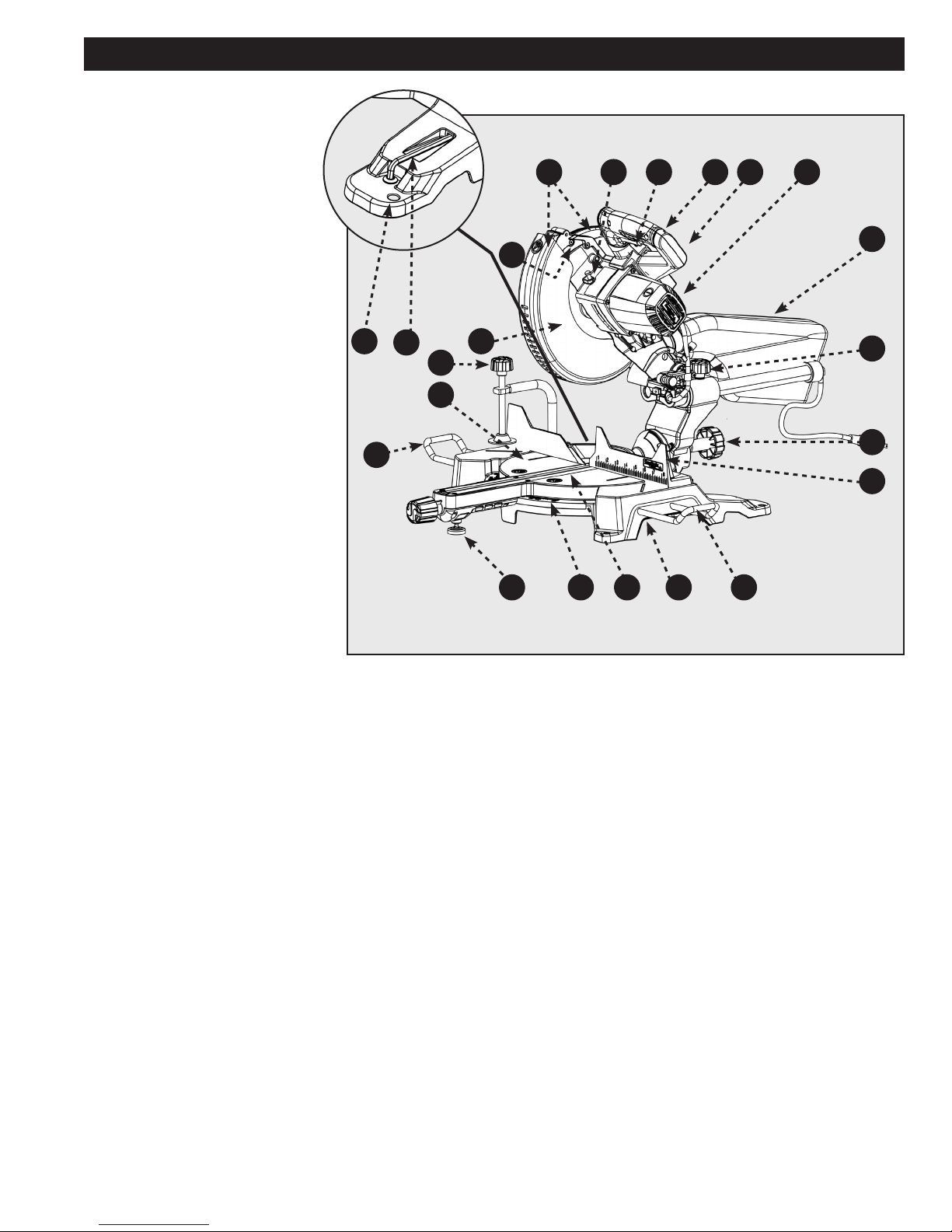
A. Motor
B. Fence
C. Throat Plate
D. Mitre Lock Knob
E. Support Extensions
F. Mitre Scale with Positive Stops
G. Horizontal Work Clamp
H. Base with Carry Handles
I. Mounting Holes
J. On-Board Wrench
K. Work Table
L. Bevel Lock Knob
M. Dust Bag
N. Upper and Lower Blade Guards
O. Blade (not visible)
P. Saw Head Handle
Q. Spindle lock
R. Slide Lock Knob
S. Electric Brake (not shown)
T. Laser
U. Power Switch (not visible)
V. Power Safety Toggle
x4
FEATURES
U PV
QN
T
I
J
O
G
K
E
F
FIGURE 1
CD
H
E
A
M
R
L
B
KNOW YOUR COMPOUND MITRE SAW
Refer to Figure 1.
Using this tool safely requires that you understand the
information provided in this operator’s manual, as well as
the project you are attempting. Before using this product,
familiarize yourself with all operating features and safety
rules.
A. 15-AMP MOTOR: This tool features a powerful
15-amp motor with all ball bearings and externally
accessible brushes for ease of servicing.
B. FENCE: The mitre fence supports the workpiece
when making all cuts.
C. THROAT PLATE: The throat plate supports the
workpiece and provides a safe working surface.
D. MITRE LOCK: The mitre lock knob securely locks the
saw at desired mitre angles.
E. SUPPORT EXTENSIONS: Use these to help support
large pieces when necessary.
F. MITRE SCALE WITH POSITIVE STOPS: Positive
stops have been provided at 0°, 15°, 22-1/2°, 31.6°,
and 45°. The blade stops have been provided on
both the left and right side of the mitre table.
G. HORIZONTAL WORK CLAMP: The horizontal work
clamp helps to position and secure the workpiece
to the fence, ensuring safer operation and more
accurate cuts.
H. BASE WITH CARRY HANDLES: Supports the tool
and features mounting holes. Use the carry handles
which are designed into the base for safe and easy
transportation of the saw.
I. MOUNTING HOLES: Enable you to securely mount
the tool to a stable surface.
J. BLADE WRENCH STORAGE: The included blade
wrench features a Phillips screwdriver at one
end and a hex key at the other. Use the hex key
when installing or removing blade and the Phillips
screwdriver when removing or loosening screws.
When not in use, the wrench can be stored in the
base of the saw.
K. WORK TABLE: Sturdy, large die-cast aluminum work
table provides a level and sturdy work surface.
L. BEVEL LOCK: the bevel lock knob secures the saw
at the desired angle for bevel cuts. There are positive
stop screws on each side of the saw arm for making
fine adjustments at 0° and 45°.
M. DUST COLLECTION BAG: The included dust bag
attaches and detached quickly with the integrated
clamp for easy cleaning.
7
Page 8
FEATURES
N. UPPER AND LOWER BLADE GUARDS: The lower
blade guard is made of shock-resistant, see-through
plastic that provides protection from each side of the
blade. It automatically retracts over the upper blade
guard as the saw is lowered into the workpiece.
O. 10-INCH BLADE: A 10 in. blade is included with the
compound mitre saw. It will cut materials up to 3-1/2
in. thick or 12 in. wide, depending upon the angle at
which the cut is being made.
P. SAW HEAD HANDLE: Use this handle to perform
cuts as instructed in the operation section of this
manual. This handle also includes the power switch
for activating the saw blade.
Q. SPINDLE LOCK BUTTON: The spindle lock button
locks the spindle preventing the blade from rotating
while removing or installing the blade screw.
R. SLIDE LOCK: This allows head to move front to rear
for cutting wide material up to 12” wide
S. ELECTRIC BRAKE: An electric brake has been
provided to more quickly stop blade rotation after the
switch is released. (not shown)
T. LASER: For more accurate cuts, a laser is included
with your mitre saw. When used properly, the laser
makes accurate, precision cutting simple and easy.
U. POWER SWITCH: The saw blade is activated by
an easy-to-use switch. When not in use the saw
should be disconnected from the power supply and
switch locked in the off position using a padlock
(not included) inserted through the hole in the switch
trigger. A lock with a long shackle up to 5/16 in.
diameter may be used. The padlock and key should
be stored in separate locations.
V. POWER SAFETY TOGGLE: Reduces safety risk for
unauthorized users.
UNPACKING AND ASSEMBLY
Check shipping carton and machine for damage before unpacking. Carefully remove packaging materials, parts and
machine from shipping carton. Always check for and remove protective shipping materials around motor and moving
parts. Lay out all parts on a clean work surface.
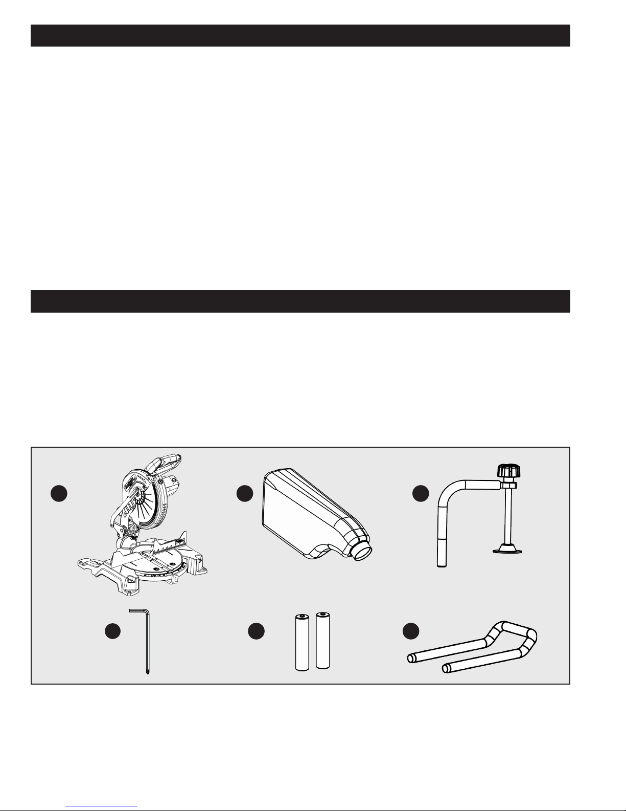
Compare the items to inventory figures, verify that all items are accounted for before discarding the shipping carton.
Report any missing or damaged parts, please call Company’s Customer Care Center at 800-223-7278. Prior to tool
assembly and use, read this manual to thoroughly familiarize yourself with proper assembly, maintenance and safety
procedures.
If any parts are missing, do not attempt to plug in the power cord and turn the power on. The saw should only be
energized after all parts have been located and correctly assembled.
A
D
CONTENT DESCRIPTION (QTY)
A. SHOPMASTER #S26-263L 10-inch Sliding
Compound Mitre Saw
B. Dust Collection Bag (1)
C. Horizontal Work Clamp (1)
B
E F
FIGURE 2
D. Blade Wrench (1)
E. AAA Batteries (2)
F. Support Extensions (2)
8 9
C
Page 9
MOUNTING AND TRANSPORTATION
Before moving/transporting your saw it is important to make sure all of the following steps have been
followed to ensure a safe condition for transportation. Failure to do so can result in serious personal injury.
• Always turn the power off and unplug saw before transporting.
• Secure power cord to avoid any snags or hang ups during transportation.
• Always lift using the strength of your legs to lift saw; never use your back muscles to lift saw.
• Do not use power On/Off switch handle or power cord to lift your saw.
• Always place the saw onto a stable and level surface with clearance for handling and maneuvering.
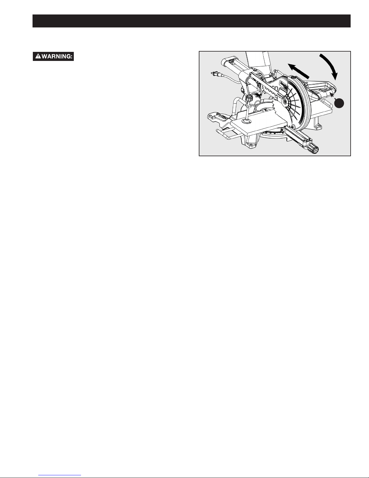
PREPARATIONS FOR TRANSPORTATION
1. The saw is shipped with the arm secured in the down
position as shown in Figure 3. To release the arm,
push it down, cut the plastic tie and release the lock
pin (A).
2. Lock pin (A) is for storage and transport only. Saw is
not to be locked in down position during cuts.
3. Inspect the tool carefully to make sure no damage
occurred during shipping.
4. Do not discard the packaging material until you have
carefully inspected and satisfactorily operated the
tool.
Saw Head lock pin is for storage and
transport only. This saw should never be locked in the down
position while making cuts.
FIGURE 3
A
BASE WITH CARRY HANDLES
Use the carry handles which are designed into the base for
safe and easy transportation of the saw. Shown in Fig. 4.
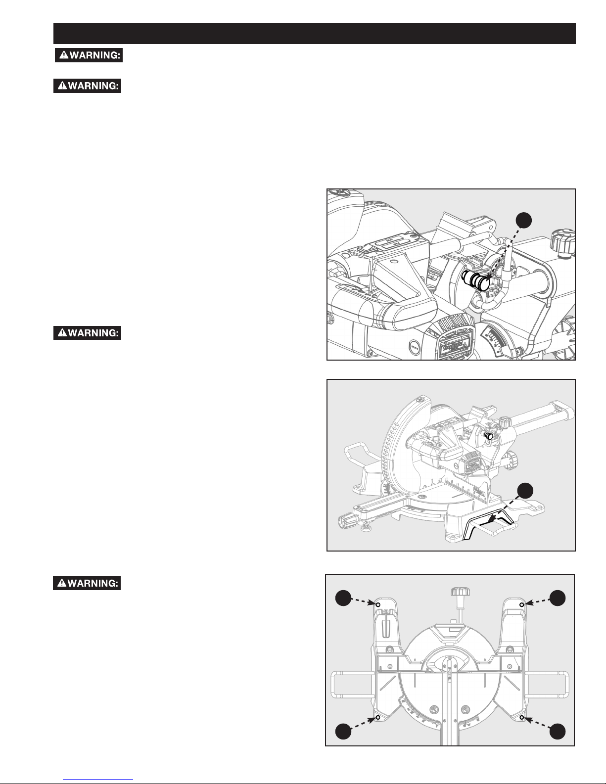
MOUNTING THE SAW TO A
STABLE SURFACE
To ensure safe and accurate operation,
this saw should be mounted to a stable
and level surface such as a workbench. To mount the tool
to a stable surface, refer to Figure 5 and do the following:
1. Locate the four mounting holes in the base of the
saw (C).
2. Secure the tool to the mounting surface using 3/8”
diameter machine bolts, lock washers, and hex nuts
(not included). Make sure the bolts are long enough
to accommodate the saw base, lock washers, hex
nuts, and the thickness of the workbench.
3. Tighten all four bolts securely.
4. Check to make sure that the saw is secure before
operation.
B
FIGURE 4
C
C
FIGURE 5
C
C
9
Page 10

ASSEMBLY
• Do not attempt to modify this tool or create accessories not recommended for use with this tool. Any such alteration
or modification is misuse and could result in a hazardous condition.
• Do not connect to power supply until assembly is complete. Failure to comply could result in accidental starting.
• Do not start the mitre saw without checking for interference between the blade and the mitre fence. Damage could
result to the blade if it strikes the mitre fence during operation of the saw.
• The saw can tip over if the saw head is released suddenly and the saw is not secured to a work surface. ALWAYS
secure this saw to a stable work surface before any use.
• If any parts are damaged or missing do not operate this tool until the parts are replaced. Please call Customer Care
Center at 800-223-7278, for instructions.
SUPPORT EXTENSIONS
See Figure 6.
Table extensions have been provided for both the left and
right side of the saw.
To install table extensions:
• Insert the ends of extension (A) into holes in the sides
of the base (B).
• Thread Hex-Socket Cap Screw (C) into the end of
extension (A). Tighten screw.
• Repeat for other extension.
• Always fix and use workpiece
support extensions during operation.
A
B
FIGURE 6
C
ATTACHING WORK CLAMP
The horizontal work clamp secures the workpiece to the
fence to provide more stability and keeps the workpiece
from creeping toward the saw blade. Depending on the
cutting operation and the size of the workpiece, it may be
preferable to use a C-clamp instead of the work clamp
to secure the workpiece to the mitre table prior to making
the cut.
To install the horizontal work clamp, see Figure 7 and do
the following:
1. Place the clamp shaft (D) in either hole (E) on the
mitre table base.
2. Rotate the knob (F) on the clamp clockwise to move
it in or counter clockwise to move it out as needed.
INSTALL DUST COLLECTION BAG
The tool includes a dust collection bag that attached over
the exhaust port on the upper blade guard. To install,
slide the plastic collar (G) of the dust bag onto the dust
port (H). See Figure 8.
NOTE: To remove the dust bag for emptying, simply
reverse the above procedure.
F
E
FIGURE 7
G
H
D
FIGURE 8
10 11
Page 11
ASSEMBLY
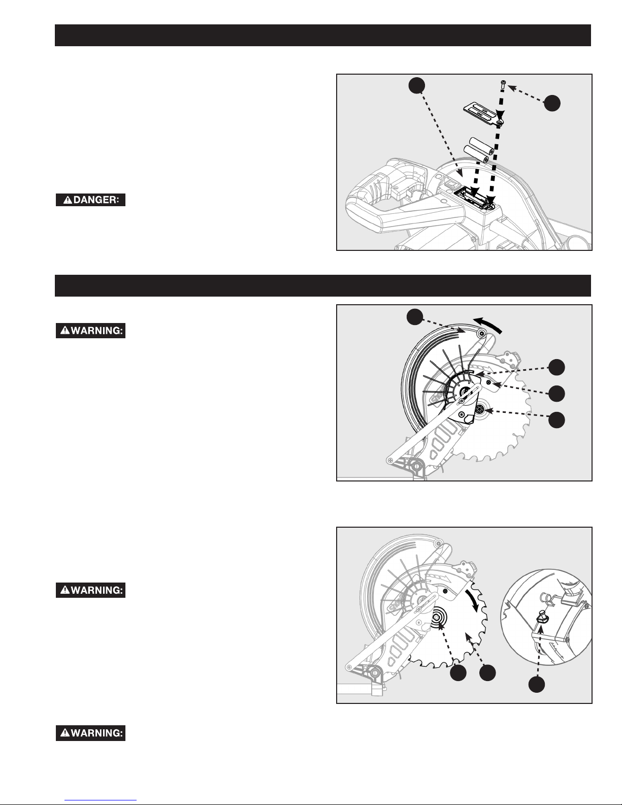
INSTALL BATTERIES FOR LASER
1. The battery compartment (A) is located in the control
arm on the rear of the saw. See Figure 9.
2. Using the Phillips end of the supplied blade wrench,
remove the screw (B) securing the compartment
cover and lift off the cover.
3. Install two AAA batteries (supplied) as shown on the
diagram in the compartment.
4. Replace the cover and secure with the screw.
Laser radiation. Avoid direct eye contact
with light source.
PREPARING YOUR SAW FOR USE
INSTALL/REPLACE THE BLADE
According to the markings on the saw a
10-inch blade is the maximum blade
capacity of the saw. Larger blades will come in contact with
the blade guards. Only use blades which are rated for at
least 5,500 RPM or higher. Only use blades with a maximum
kerf width of 2.7mm or less.
1. Make sure the saw is unplugged.
2. Raise the saw arm to the full upright position.
3. In Figure 10, Rotate the lower blade guard (C) up.
Slightly loosen the blade bolt cover screw (D) until you
can move the blade bolt cover (E) up to expose the
blade bolt (F).
Refer to Figure 11.
4. Press the spindle lock button (G).
5. If replacing the blade, carefully rotate the old blade until
the spindle locks in place.
6. Using the supplied blade wrench, remove the blade bolt
(F) by turning it clockwise.
NOTE: The blade bolt has left-hand threads.
7. Remove only the outer blade washer (H) and the blade
(I), leaving the inner blade washer on the spindle.
If inner blade washer has been removed,
replace it before placing blade on spindle.
Failure to do so could cause an accident since blade will not
tighten properly.
8. Carefully fit saw blade inside the lower blade guard and
guide it onto spindle, ensuring the teeth of the blade are
facing down at the front of the saw.
9. Align the double “D” flats on the blade washer with the
flats on the spindle and fit the washer onto the spindle.
10. Lock the spindle by depressing the spindle lock button.
Replace blade bolt, remembering to thread it counter
clockwise. Tighten blade bolt securely.
Always install the blade with the blade teeth and the arrow on the side of the blade pointing down at
the front of the saw. The direction of the blade rotation is also stamped with an arrow on the upper
blade guard.
A
B
FIGURE 9
C
E
D
F
FIGURE 10
IH
G
FIGURE 11
11
Page 12
PREPARING YOUR SAW FOR USE
11. Replace the blade bolt cover and tighten blade bolt cover screw securely. Lower blade guard.
12. Raise and lower the saw arm to ensure that the arm and blade guard move freely.
Make sure the spindle lock button is not engaged before reconnecting saw to power source. Never
engage spindle lock button when blade is rotating.
NOTE: Some illustrations in this manual indicate only portions of the saw. This is done in order to more clearly show key
areas and components of the saw. Never operate the saw without all guards securely in place and in good operating
condition.
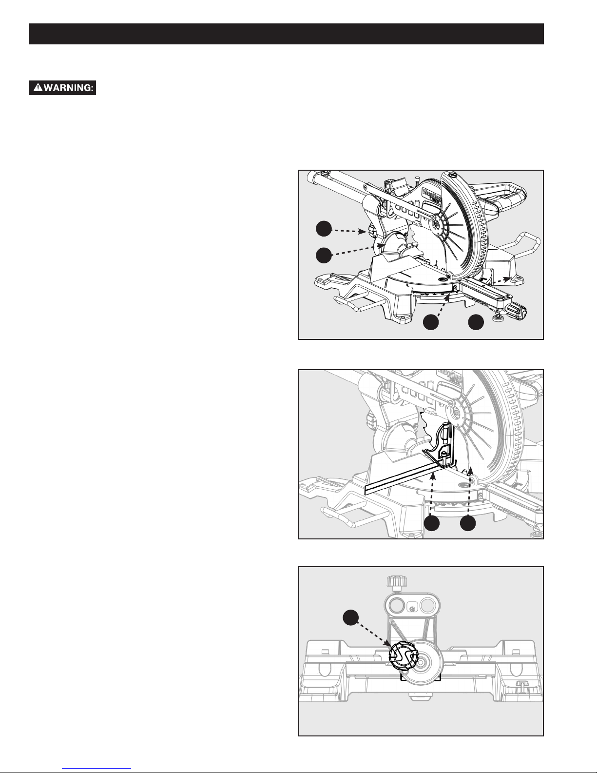
ALIGN THE BLADE TO THE TABLE
Refer to Figure 12.
1. Unplug the saw
2. Lower the saw arm all the way down to the transport
position and engage the lock pin to hold it in place.
3. Rotate the mitre lock handle (A). Position the table so
that the mitre scale indicator ( B) reads 0°.
4. Rotate the mitre lock handle to the locked position so
that the table will not move.
5. Loosen bevel lock knob (D) and adjust the angle of
saw arm so that the bevel scale indicator (C) reads
0°. This positions the blade at 90° to the table.
6. Securely tighten bevel lock knob.
7. Place a combination square (E) against the table and
the face of the saw blade (F).
NOTE: Make sure that the square contacts the flat part of
the saw blade, not the blade teeth.
8. Rotate the blade by hand and check the blade-to-
table alignment at several points.
9. The edge of the square and the saw blade should be
parallel as shown in Figure 13.
10. If the top or bottom of the blade face is not flush with
the square, refer to Figure 14 below and perform the
following steps.
11. Loosen bevel lock knob (G).
12. Adjust positive stop adjustment screw (not shown) to
bring saw blade into alignment with the square. See
“Positive Stop Screw” in the Adjustment section.
13. Re-tighten bevel lock knob. Recheck blade-to-blade
alignment.
NOTE: The above procedure can be used to check
alignment of the blade to the mitre table at both 0° and
45° angles.
The saw has two scale indicators, one on the bevel scale
and one on the mitre scale. After squaring adjustments
have been made, it may be necessary to loosen the
indicator screws and reset them to zero.
D
C
FIGURE 12
FIGURE 13
B
A
E
F
G
FIGURE 14
12 13
Page 13
PREPARING YOUR SAW FOR USE
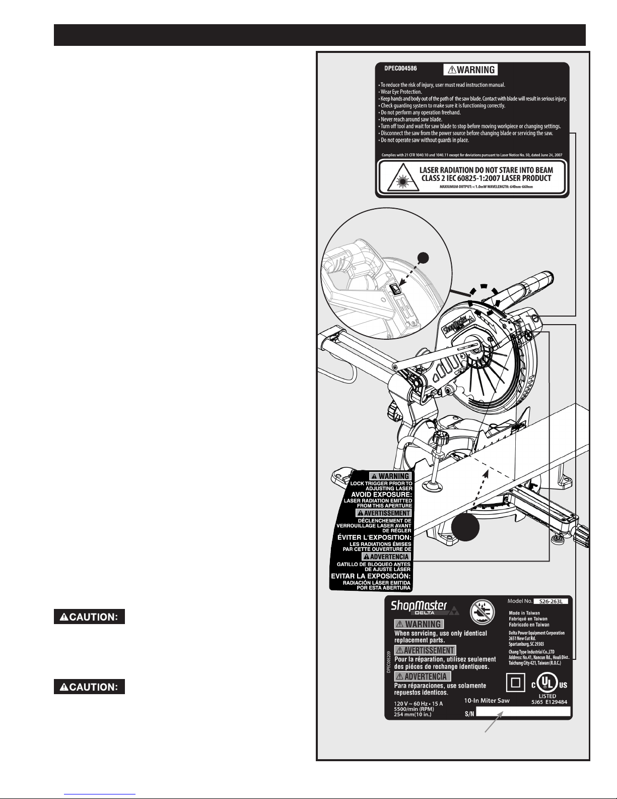
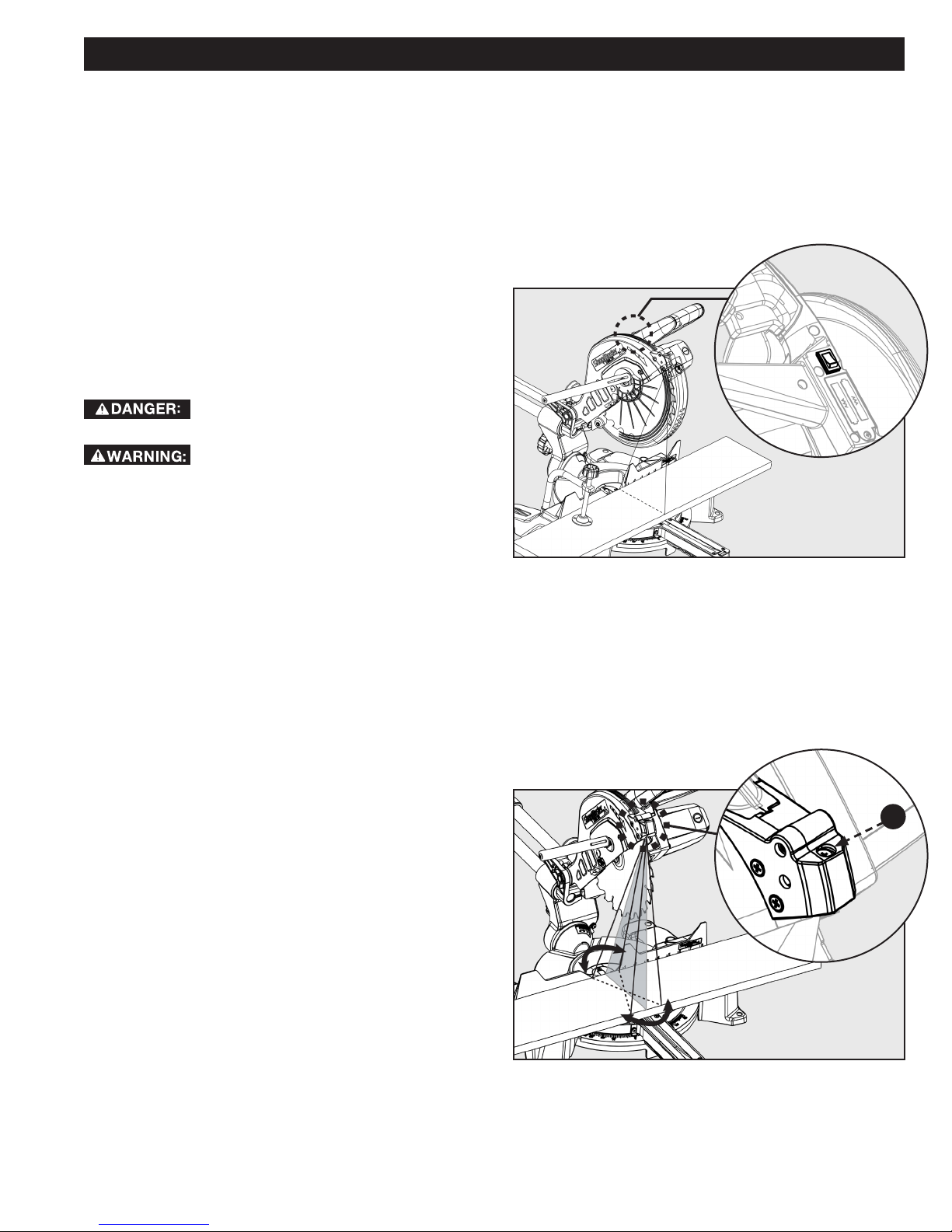
USING THE LASER GUIDE
Refer to Figure 15.
When the laser guide switch is turned on it projects a red
line onto the work surface enabling you to see your cut
before you make it. To ensure a true and straight cut:
1. Make sure the saw is unplugged.
2. Draw a line on the workpiece where you plan to cut.
3. Flip the laser switch (A) on the “ON” position.
4. The red line (B) indicates the path of the blade.
5. Align the laser line and the mark with the blade at the
uppermost position.
6. Once both lines are in alignment, do not move the
workpiece.
7. Plug the saw into the power source.
8. Make several practice cuts on different styles and
thickness of material.
9. Repeat the steps above is necessary.
TO REMOVE YOUR MARK:
Position the laser line near the left edge of your mark on
the work surface in order to cut the mark.
APPLICATIONS
A
TO CUT ON YOUR MARK:
Position the laser line near or over your mark on the work
surface in order to cut the mark.
TO CUT WITHOUT REMOVING YOUR MARK:
Position the laser line near the right edge of your mark on
the work surface in order to leave the mark,
After you have become familiar with using the laser
guide, you will be able to remove, cut, or leave your mark
on the work surface. Practice will teach you the correct
position for aligning the laser line with your mark.
FREE WARNING LABEL REPLACEMENT
If your warning labels become illegible or are missing,
user shall remake the label according to copy on manual
and attach on the same location or call 1-800-223-7278
for a free replacement.
During operation and maintenance, human access to
laser radiation in excess of the accessible emission limit
is possible, so it should avoid direct eye exposure of laser
radiation.
Complies with 21 CFR 1040.10 and 1040.11 Use of
controls or adjustments or performance of procedures
other than those specified herein may result in hazardous
radiation exposure.
B
Metal instruments can cause a laser reflector. During
operation and maintenance should avoid direct exposure
in these instruments, as far as possible not to use
reflective instruments. Action should be avoided with
watches, necklaces, bracelets, it can be reflected laser
accessories.
14AB000001211401CT
EXAMPLE SERIAL NUMBER, FOR
REFERENCE ONLY
FIGURE 15
13
Page 14
OPERATION
Do not allow familiarity with tools to make you careless. Remember that a careless fraction of a second
is sufficient enough to inflict serious personal injury.
• Always wear eye protection with side shields and marked to comply with ANSI Z87.1 Failure to do so could result in
objects being thrown into your eyes, resulting in possible serious personal injury.
• Do not use any attachments or accessories not recommended by the manufacturer of this tool. The use of
attachments or accessories not recommended can result in serious personal injury.
• Before starting any cutting operation, clamp or bolt the compound mitre saw to a workbench. Never operate the
mitre saw on the floor or in a crouched position. Failure to heed this warning can result in serious personal injury.
• To avoid serious personal injury, always tighten the mitre lock handle and bevel lock knob securely before making a
cut. Failure to do so could result in movement of the control arm or mitre table while making a cut.
• To avoid serious personal injury, keep hands outside the no hands zone, at least 3 in. from blade. Never perform any
cutting operation freehand (without holding workpiece against the fence). The blade could grab the workpiece if it
slips or twists.
• When using a work clamp or C-clamp to secure the workpiece, clamp workpiece on one side of the blade only. The
workpiece must remain free on one side of the blade to prevent the blade from binding in workpiece. The workpiece
binding the blade will cause motor stalling and kickback. This situation could cause an accident resulting in serious
personal injury.
• NEVER move the workpiece or make adjustment to any cutting angle while the saw is running and the blade is
rotating. Any slip can result in contact with the blade causing serious personal injury.
When cutting, do not force the blade against the workpiece. Forcing the blade will cause a drop in motor RPM and
•
increase the risk of overheating the saw blade tips.
You may use this tool for the following purposes:
• Bevel cutting and compound cutting for crown moldings, etc.
• Cross cutting wood
• Cross cutting for moldings, door casings, picture frames, etc.
NOTE: This saw is for cutting wood. The blade provided is acceptable for wood cutting only.
POWER SWITCH LOCK-OUT
To prevent any unauthorized person from operating this
saw, a padlock (not included) should be installed into
the Lock Hole located on the power switch, as shown
in Figure 16. Be sure padlock is fully closed and locked
before leaving this saw unattended.
Always disconnect the power supply
before installing or removing a lock
onto the power switch. Failure to
do so could cause the power switch
to engage by accident, resulting in
serious injury.
FIGURE 16
POWER SAFETY TOGGLE
In order to turn the saw motor on, you must first engage
the power safety toggle located on the power switch
handle as shown in figure 17.
FIGURE 17
14 15
Page 15
OPERATION
TO SLIDE CUT
Never make a cut by pulling the saw
toward you. The blade can “climb” on
top of the workpiece and come toward you at an
accelerated speed. Failure to heed this warning could
result in serious personal injury.
See Figure 18.
With the saw off, pull the saw arm forward. Turn the saw
on (wait for blade to reach full speed). push the blade
down cutting into the workpiece, then back toward the
rear of the saw to make a cut. Cuts must be made by
pushing the saw blade away from you and toward the
back of the saw stopping at the maximum rear position
after each cut. While the saw is running, NEVER pull the
saw blade toward you or toward the front of the saw. See
warning above.
• Raise arm to its full height.
• Place the workpiece flat on the mitre table with
one edge securely against the fence. If the board is
warped, place the convex side against the fence. If
the concave edge of a board is placed against the
fence, the board could collapse on the blade at the
end of the cut, jamming the blade.
• When cutting long pieces of lumber or molding,
support the opposite end of the stock with a stand or
with a work table level with the saw table.
• Align the cutting line on the workpiece with the blade
or laser line.
• Loosen the slide lock knob.
• Hold the stock firmly with one hand, against the
fence. Use the work clamp to secure the workpiece
whenever possible.
• With the saw off, perform a dry run of the cut to
make sure that no problems will occur when the
actual cut is made.
• With the saw off, grasp the saw handle firmly then
pull the saw forward until the center of the saw blade
is over the front edge of the workpiece or until the
saw is fully extended.
• Only use the saw handle (A) to place your hands. DO
NOT place your hands on the motor housing.
• Squeeze the switch trigger. Allow the blade to reach
maximum speed.
• Slowly lower the blade through the front edge of the
workpiece.
• While holding the workpiece push the saw handle
away from you and toward the back of the saw.
• Release the switch and allow the saw blade to stop
rotating before raising the blade out of workpiece.
After blade stops, remove the workpiece from mitre
table.
NOTE: A cross cut is made by cutting across the grain of
the workpiece. A straight cross cut is made with the mitre
A
FIGURE 18
table set at the 0° position. Mitre cross cuts are made
with the mitre table set at some angle other than 0°
BEVEL CUTS
A bevel cut is made across the grain with the blade
angled to the workpiece. A straight bevel means the mitre
scale indicator is set at 0° and the bevel scale indicator is
set at an angle other than 0°.
COMPOUND MITRE CUTS
A compound mitre cut is made using a mitre angle and a
bevel angle at the same time. Adjustments of mitre and
bevel settings are interdependent. Each time you adjust
the mitre setting change the effect of the bevel setting.
Also, each time you adjust the bevel setting you change
the effect of the mitre setting.
15
Page 16

OPERATION
TIPS FOR CUTTING AND SUPPORTING WORKPIECES
TIPS FOR CUTTING CROWN MOLDING
• The two edges of the molding that contact the ceiling and the wall are at angles that, when added together, equal
exactly 90°. Most crown molding has a top rear angle (the section that fits flat against the ceiling) of 52° and a
bottom rear angle (the section that fits flat against the wall) of 38°.
• To accurately cut crown molding for a 90° inside or outside corner, lay the molding with its broad back surface flat
on the mitre table and against the fence.
• The angles for crown moldings must be very precise. The bevel and mitre angles are interdependent; changing one
angle changes the other angle as well.
• Since it is very easy for the work piece to shift, all settings should first be tested on scrap molding. Also most walls
do not have angles of exactly 90°; therefore, you will need to fine-tune your settings.
• When cutting crown molding the bevel angle should be set at 33.85°.
• The mitre angle should be set at 31.62° either right or left, depending on the desired cut for the application. See the
chart below for correct angle settings and correct positioning of crown molding on the work table.
Bevel Angle Setting Type of Cut Steps
33.85° Left side, inside corner 1. Top edge of molding against fence
2. Mitre table set right 31.62°
3. Save left end of cut
33.85°
33.85° Left side, outside corner 1. Bottom edge of molding against fence
33.85° Right side, outside corner 1. Top edge of molding against fence
Right side, inside corner 1. Bottom edge of molding against fence
2. Mitre table set left 31.62°
3. Save left end of cut
2. Mitre table set left 31.62°
3. Save right end of cut
2. Mitre table set right 31.62°
3. Save right end of cut
16 17
Page 17
OPERATION
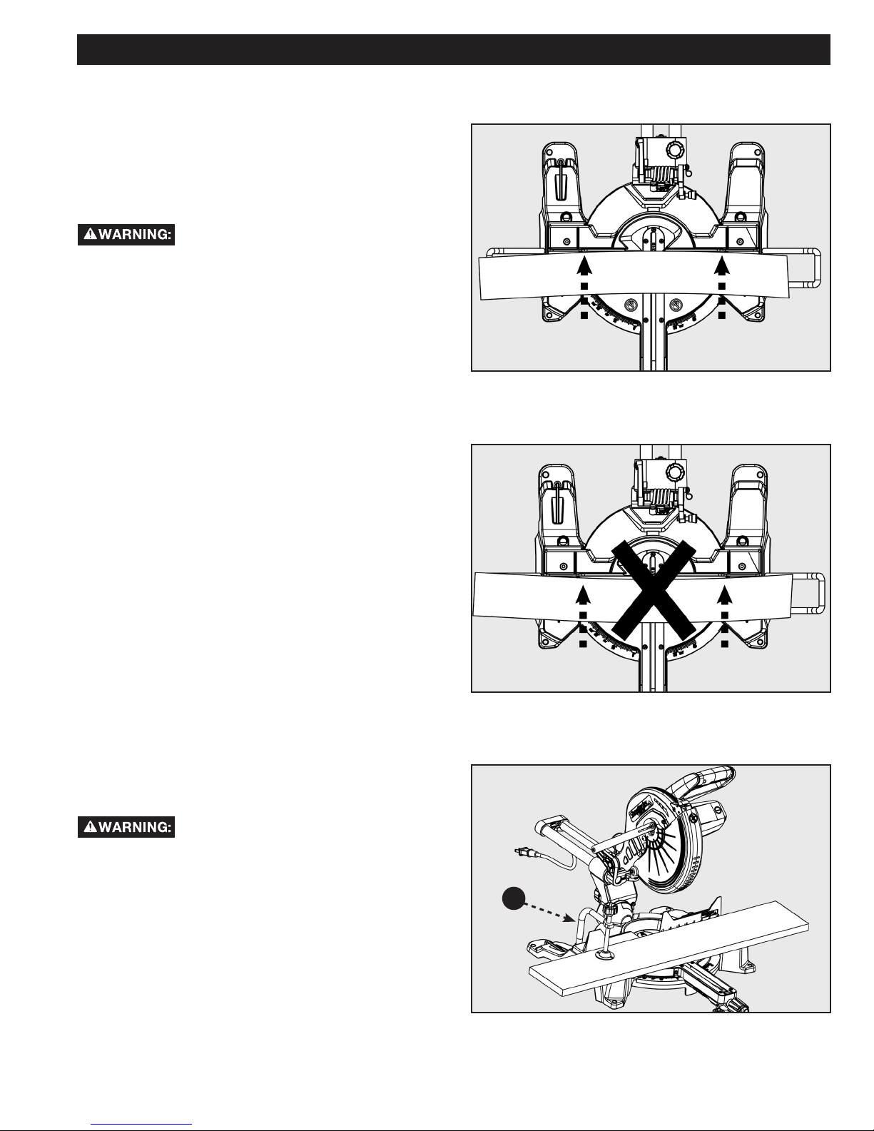
CUTTING WARPED MATERIAL
When attempting to cut warped material, the CONVEX
face should be against the fence as shown in Figure 19.
Never position a piece of warped material with the
CONCAVE face or edge against the fence, as shown in
Figure 20. It will pinch the blade near the completion of
the cut.
To avoid a kickback and to avoid serious
personal injury, never position the
concave edge of bowed or warped material against the
fence.
FIGURE 19
CLAMPING WIDE WORKPIECES
When cutting wide work pieces, such as 2 in. X 12 in.,
clamp the workpiece to the work table using a work
clamp as shown in Figure 21.
Keep clamps away from the path of the
blade and blade guard assembly.
FIGURE 20
A
FIGURE 21
17
Page 18

OPERATION
SUPPORTING LONG WORKPIECES
In most cases the included table extensions
(workpiece supports) will be sufficient to support
longer workpieces. If these are not long enough, the
workpiece should be supported further out from the
saw. Additional support (A) may be used to make
the workpiece lay flat on the saw table. Use the
included work clamp or a C-clamp (B) to secure the
workpiece to the mitre saw table. See Figure 22.
Keep clamps away from the path of
the blade and blade guard assembly.
A
FIGURE 22
B
ADJUSTMENTS
Before performing any adjustment, make sure the tool is unplugged from the power supply. Failure to
heed this warning could result in serious personal injury.
Your compound mitre saw has been properly adjusted at the factory. Due to shipping or normal use, it may be necessary
to re-adjust some of the settings. Check the following adjustments periodically to assure proper accuracy and safe
operation.
Check for interference between the blade and the throat plate, before plugging the saw into the power
source.
ARM PIVOT
The arm of the saw should raise and lower completely and freely. In the lowered position and with the lock pin removed,
the arm should rise to the up position by itself. If the saw arm does not raise by itself or if there is play in the pivot joints,
it will need to be professionally repaired at an AUTHORIZED SHOPMASTER SERVICE CENTER. Please call Company’s
Customer Care Center at 800-223-7278.
POSITIVE STOP SCREW
The position of the positive stop adjustment screw was set
at the factory and normally will not require readjustment.
If the blade is not square to the table, the positive stop
adjustment screw must be re-adjusted.
To adjust refer to Figure 23.
1. Unplug the saw
2. Using the Phillips end of the blade wrench, loosen
the positive stop adjustment screw (C) by turning it
counterclockwise.
3. Loosen the bevel lock knob (D) by turning it
counterclockwise.
4. Square the blade to the mitre table as described in the
section entitled, ALIGN THE BLADE TO THE TABLE,
found on page 12.
5. Re-tighten bevel lock knob. Recheck blade-to-table
alignment.
6. The saw has two scale indicators, one on the bevel
scale and one on the mitre scale. After squaring
adjustments have been made, it may be necessary to
loosen the indicator screws and reset them to zero.
NOTE: Use this procedure to check that the blade is square
to the table at 0° and 45° angles.
D
0° 45°
C
FIGURE 23
18 19
Page 19
ADJUSTMENTS
BEVEL PIVOT
With the bevel lock knob loosened, the control arm of the saw should tilt easily from 0° and 45°. If it does not or if there is
play in the pivot, the saw must be repaired by an AUTHORIZED SHOPMASTER SERVICE CENTER.
LASER ADJUSTMENTS
This saw is equipped with an adjustable laser which
projects a red line onto the work piece surface, see
Figure 24. Refer to the “Using Your Laser Guide” section
on page 13 for more information on how to operate laser.
This section will instruct you how to adjust the laser
alignment for more accurate cuts.
• Avoid direct eye exposure to laser beam or reflection.
Intense or prolonged exposure to laser radiation
could permanently damage your eyes. Do not project
or reflect the laser into anyone’s eyes, including your
own.
• Caution -- use of controls or adjustments or
performance of procedures other than those
specified herein may results in hazardous radiation
exposure.
• Use or modification of the laser guide for anything
other than its designed purpose may result in
hazardous radiation exposure.
Laser radiation. Avoid direct eye contact
with light source.
FIGURE 24
LASER PARALLEL ADJUSTMENT
If you notice the laser line is not perfectly parallel with
the saw blade refer to Figure 25 and follow these
instructions: using a Phillips head screwdriver turn screw
(A) until the laser line is parallel with the saw blade.
A
FIGURE 25
19
Page 20

ADJUSTMENTS
LASER VERTICAL ANGLE
ADJUSTMENT
If you notice the laser line does not remain parallel to the
blade as the saw head is lowered to make a cut refer to
Figure 26 and follow these instructions: using a Phillips
head screwdriver turn the screw (A) to adjust the vertical
angle of the laser.
LASER OFFSET ADJUSTMENT
If you notice the laser line is offset from the actual cut line
refer to Figure 27 and follow these instructions: using a
Phillips head screwdriver turn the screw (B) to adjust the
offset.
A
FIGURE 26
B
DEPTH STOP ADJUSTMENT
This mitre saw is equipped with an adjustable depth stop
for making through cuts and non-through cuts.
Refer to Figure 28 and follow these instructions in
order to set the depth stop at a specific cut depth:
use a Phillips head screwdriver to loosen screw (E) and
then rotate the stop bracket (D) counterclockwise into
the down position. Make sure to re-tighten screw (E).
The cut depth can now be adjusted by turning the depth
adjustment screw (C).
Refer to figure 28 and follow these instructions
in order to make a through cut: use a Phillips head
screwdriver to loosen screw (E) and then rotate the stop
bracket (D) clockwise into the up position. Make sure to
re-tighten screw (E).
Always check to make sure screw (E) is
tightened before making a cut. Failure to
do so may result in injury.
FIGURE 27
C
D
E
FIGURE 28
20 21
Page 21
MAINTENANCE
To reduce the risk of injury, turn unit off
and disconnect it from power source
before cleaning or servicing, before installing and
removing accessories, before adjusting when making
repairs. An accidental start-up can cause injury.
KEEP MACHINE CLEAN
Periodically blow out all air passages with dry
compressed air. All plastic parts should be cleaned
with a soft damp cloth. NEVER use solvents to clean
plastic parts. They could possibly dissolve or otherwise
damage the material. Wear certified safety equipment
for eye, hearing and respiratory protection while using
compressed air.
Empty dust bag frequently.
When servicing, use only identical
replacement parts. Use of any other
parts may create a hazard or cause product damage.
GENERAL MAINTENANCE
Avoid using solvents when cleaning plastic parts. Most
plastics are susceptible to damage from various types of
commercial solvents and may be damaged by their use.
BRUSH REPLACEMENT
Use clean cloths to remove dirt, dust, oil, grease, etc.
Do not at any time let brake fluids,
gasoline, petroleum-based products,
penetrating oils, etc., come in contact with plastic parts.
Chemicals can damage, weaken or destroy plastic which
may result in serious personal injury.
Electric tools used on fiberglass material, wallboard,
spackling compounds, or plaster are subject to
accelerated wear and possible premature failure
because the fiberglass chips and grindings are
highly abrasive to bearings, brushes, commutator,
etc. Consequently, we do not recommend using this
tool for extended work on these types of materials.
However, if you do work with any of these materials, it is
extremely important to clean the tool using compressed
air.
LUBRICATION
All of the bearings in this tool are lubricated with a
sufficient amount of high-grade lubricant for the life of
the unit under normal operating conditions. Therefore, no
further lubrication is required.
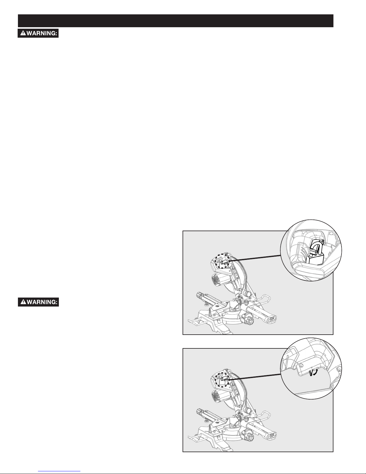
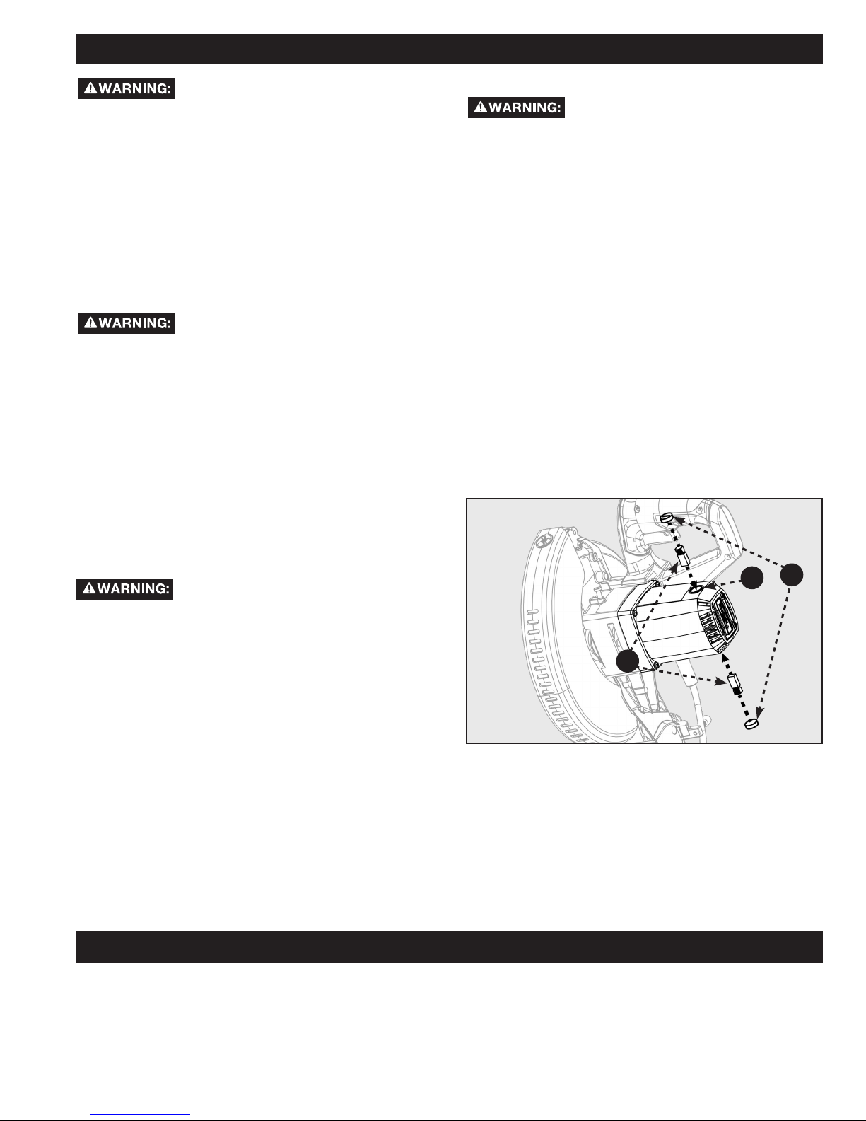
The motor on this saw features externally accessible
brush assemblies that should be periodically checked for
wear. If the brushes need to be replaced, refer to Figure
29 and proceed as follows:
1. Unplug the saw.
Failure to unplug the saw could result in
accidental starting causing serious
personal injury.
2. Using a screwdriver, carefully remove the brush cap
(A).
NOTE: Remove the cap slowly. The brush assembly is
spring-loaded and will pop out once the cap is removed.
3. Remove brush assembly (B).
4. Inspect both brushes. If either has less than 1/4 in.
length of carbon remaining, both brushes should be
replaced.
NOTE: Do not replace one side without replacing the
other.
5. Insert both brushes into the brush tube (C), making
sure the curvature of the brushes matches curvature
of motor. Brush assembly should move freely within
the tube.
6. Carefully replace the brush cap, ensuring that it is not
cross-threaded.
7. Tighten brush cap securely. Do not over-tighten.
B
FIGURE 29
C
A
FAILURE TO START
If your machine fails to start, check to make sure the prongs on the cord plug are making good contact in the receptacle.
Also, check for blown fuses or open circuit breakers in your power supply line. If the saw still does not start, call
Company’s Customer Care Center at 1-800-223-7278.
TROUBLESHOOTING
21
Page 22

ACCESSORIES
For accessories please visit our Web Site for an on-line catalog or for the name or your nearest supplier.
Since accessories other than those offered by DELTA
®
have not been tested with this product, use of
such accessories could be hazardous. For safest operation, only DELTA®/SHOPMASTER recommended
accessories should be used with this product.
PARTS, SERVICE OR WARRANTY ASSISTANCE
All SHOPMASTER Machines and accessories are manufactured to high quality standards and are serviced by a
network of DELTA
parts, service, warranty assistance, or the location of the nearest service center, please call 1-800-223-7278.
1. WHAT IS COVERED. Delta Power Equipment Corporation (“Company”) will, at its option, repair or replace this SHOPMASTER
product, if purchased at retail in the United States or Canada and the product, with normal use, has proven to be defective in
workmanship or material, subject to the conditions stated in this Limited Warranty. This Limited Warranty covers only materials
and labor. All transportation costs are Customer’s responsibility.
2. WARRANTY PERIOD. All warranty claims must be submitted within three years from the date of retail purchase. For all service
parts and factory refurbished SHOPMASTER products, the warranty period is 180 days.
3. HOW TO OBTAIN SERVICE. To obtain warranty service, you must return the defective product, at your expense, to a service center
authorized by Company to perform warranty service (a “Company Authorized Service Center”) within the applicable warranty
period, together with acceptable proof of purchase, such as your original receipt bearing the date of purchase, or product
registration number. Company reserves the right to restrict warranty claim service to the country where the purchase was made
and/or to charge for the cost to export service parts or provide warranty service in a different country. For this purpose, on-line
purchases are deemed made in the United States. For the location of your nearest Company Authorized Service Center, call
Company’s Customer Care Center at (800) 223-7278.
4. EXCLUSIONS.
• Company does not offer any warranty on products purchased in used or damaged condition.
• Company does not warrant any products purchased outside the United States or Canada
• Company will not be responsible for any damage that has resulted from normal wear, misuse, abuse or any repair or alteration
made by anyone other than a Company Authorized Service Center or a designated representative of Company’s Customer Care
Center.
• All IMPLIED WARRANTIES are expressly limited to the warranty period identied above.
• Company will not be liable for INCIDENTAL OR CONSEQUENTIAL damages.
• This limited warranty is Company’s sole warranty and sets forth the customer’s exclusive remedy with respect to defective products;
all other warranties, express or implied, whether of merchantability, tness for purpose, or otherwise, are expressly disclaimed by
Company, except as expressly stated in this warranty statement.
Some states do not allow the exclusion or limitation of incidental or consequential damages, or the limitation of implied warranties, so
the above limitations or exclusions may not apply to you. This warranty gives you specic legal rights and you may have other rights
which vary in certain states or provinces. For further details of warranty coverage and warranty repair information, call (800) 223-7278.
To register your products on-line, we encourage you to visit our website and register for a FREE DELTA
www.deltamachinery.com/register.
®
Authorized Service Centers. To obtain additional information regarding your product or to obtain
Three Year Limited Warranty
®
Member Account at http://
LATIN AMERICA: This warranty does not apply to products sold in Latin America. For products sold in Latin America, call the local
company or see website for warranty information.
REPLACEMENT PARTS
The only user replaceable parts on this tool are:
1) Saw Blade
2) Motor Brushes
All other parts not listed above must be replaced by an authorized DELTA® agent. Use only identical replacement parts.
For a parts list or to order parts, visit our website at www.DeltaMachinery.com/service. You can also order parts from
your nearest Authorized Warranty Service Center or by calling Technical Service Manager at 1-800-223-7278 to receive
personalized support from one of our highly-trained representatives.
FREE WARNING LABEL REPLACEMENT
If your warning labels become illegible or are missing, call 1-800-223-7278 for a free replacement.
SERVICE AND REPAIRS
All quality tools will eventually require servicing and/or replacement of parts. For information about Delta Power
Equipment Corporation, its factory-owned branches, or to locate an Authorized Warranty Service Center, visit our
website at www.DeltaMachinery.com/service or call Customer Care at 1-800-223-7278. All repairs made by our service
centers are fully guaranteed against defective material and workmanship. We cannot guarantee repairs made or
attempted by others. By calling this number you can also find answers to most frequently asked questions 24 hours/day.
You can also write to us for information at Delta Power Equipment Corporation, 2651 New Cut Road, Spartanburg, SC
29303 - Attention: Technical Service Manager. Be sure to indicate all of the information shown on the nameplate of your
saw (model number, type, serial number, date code, etc.).
22 23
Page 23

10-INCH SLIDING COMPOUND MITRE SAW
SCIE À ONGLET COMBINE
254 MM
SIERRA INGLETADORA
COMPUESTA DE 10
PULGADAS
Français (23)
Español (46)
www.DeltaMachinery.com
Instruction Manual
Manual d’utilisation
Manual de instrucciones
AVERTISSEMENT :
Pour réduire les risques de blessure grave, veuillez lire attentivement et respecter
toutes les mises en garde et directives dans ce guide et sur le produit.
CONSERVEZ CE GUIDE PRÈS DE VOTRE PRODUIT POUR RÉFÉRENCE ET POUR INSTRUIRE LES AUTRES
S26-263L
23
Page 24

TABLE DES MATIÈRES
CONSIGNES IMPORTANTES DE SÉCURITÉ ....................... 24
RÈGLES DE SÉCURITÉ GÉNÉRALES POUR LES
OUTILS ÉLECTRIQUES .......................................................... 25
RÈGLES DE SÉCURITÉ DE LA SCIE À ONGLETS ............... 26
AVERTISSEMENT DE LA PROPOSITION 65 .......................27
BRANCHEMENTS D’ALIMENTATION ...................................27
FONCTIONS ............................................................................. 28
DÉBALLAGE ET MONTAGE ................................................... 30
MONTAGE ET TRANSPORT ................................................... 31
PRÉPARATIFS POUR LE TRANSPORT ............................ 31
GOUPILLE DE VERROUILLAGE DU BRAS DE SCIE ....... 31
BASE ET POIGNÉES DE TRANSPORT ............................ 31
MONTAGE DE LA SCIE SUR UNE SURFACE STABLE .... 31
MONTAGE ................................................................................ 32
RALLONGES DE SUPPORT ............................................. 32
FIXER L'ÉTAU .................................................................... 32
INSTALLER LE SAC À POUSSIÈRE.................................. 32
INSTALLER LES PILES POUR LASER .............................. 33
PRÉPARER VOTRE SCIE POUR L’UTILISATION .................33
INSTALLER/REMPLACER LA LAME ................................ 33
ALIGNER LA LAME À LA TABLE ...................................... 34
UTILISATION DU GUIDE LASER ...................................... 35
UTILISATION ............................................................................ 36
BLOQUEO DEL INTERRUPTOR DE ENCENDIDO/..............
APAGADO ..........................................................................36
DISPOSITIVO DE SEGURIDAD ELÉCTRICA .................... 36
FAIRE UNE COUPE EN GLISSIÈRE .................................37
CONSEILS POUR LA DÉCOUPE ET LE SOUTIEN
DE PIÈCE ........................................................................... 38
COUPE DE MATÉRIAU DÉFORMÉ ................................... 39
SERRAGE DES GRANDES PIÈCES ................................. 39
SOUTIEN DES LONGUES PIÈCES ................................... 40
RÉGLAGES .............................................................................. 41
PIVOT POUR COUPE BISEAUTÉE ................................... 41
RÉGLAGE DU PARALLÈLE DU LASER ............................ 41
RÉGLAGE DE L’ANGLE VERTICAL DU LASER................ 42
RÉGLAGE DU DÉPORT DU LASER .................................42
AJUSTEMENT DE LA PROFONDEUR...............................42
ENTRETIEN .............................................................................. 43
REMPLACEMENT DES BROSSES ................................... 43
DÉPANNAGE ............................................................................44
ACCESSOIRES ........................................................................ 44
ASSISTANCE POUR PIÈCES, SERVICES OU
GARANTIE ............................................................................... 44
CONSIGNES IMPORTANTES DE SÉCURITÉ
AVERTISSEMENT :
VOTRE PRODUIT DANS CE GUIDE ET SUIVEZ-LES TOUS. CONSERVEZ CE GUIDE. ASSUREZ-VOUS
QUE TOUS LES UTILISATEURS SONT FAMILIERS AVEC LES AVERTISSEMENTS ET INSTRUCTIONS
AVANT D'UTILISER L'OUTIL. Un mauvais fonctionnement, un mauvais entretien ou une modification des outils ou du
matériel peuvent entraîner des blessures graves et/ou des dommages matériels.
LISEZ ATTENTIVEMENT LES AVERTISSEMENTS ET LES INSTRUCTIONS SUR
LOGOS DE SÉCURITÉ
Ce guide contient des informations qu’il est important que vous connaissiez et compreniez. Ces informations concernent
VOTRE SÉCURITÉ et la PRÉVENTION DE PROBLÈMES AVEC L’ÉQUIPEMENT. Pour vous aider à reconnaître ces
informations, nous utilisons les symboles ci-dessous. Veuillez lire le guide et prêter attention à ces sections.
Indique une situation dangereuse imminente qui, si elle n'est pas évitée, entraînera la mort ou des
blessures graves.
AVERTISSEMENT :
MISE EN GARDE :
MISE EN GARDE :
Ne placez pas les outils électriques sous la pluie ou dans un environnement humide.
Indique une situation dangereuse potentielle qui, si elle n'est pas évitée, pourrait entraîner la mort
ou des blessures graves.
Indique une situation dangereuse potentielle qui, si elle n'est pas évitée, pourrait entraîner des
blessures mineures ou modérées.
L’utilisation sans le symbole d'alerte de sécurité indique une situation potentiellement dangereuse qui,
si elle n’est pas évitée, pourrait entraîner des dommages matériels.
Des informations supplémentaires concernant l’utilisation appropriée et sécuritaire de cet outil sont disponibles dans les
sources suivantes :
• Power Tool Institute, 1300 Sumner Avenue, Cleveland, OH 44115-2851 ou en ligne sur www.powertoolinstitute.com
• National Safety Council, 1121 Spring Lake Drive, Itasca, IL 60143-3201
• American National Standards Institute, 25 West 43 rd Street, 4th floor, New York, NY 10036 www.ansi.org —
exigences de sécurité ANSI 01.1 pour machines à bois
• Ministère du Travail du gouvernement américain, www.osha.gov
24 25
Page 25

RÈGLES DE SÉCURITÉ GÉNÉRALES POUR LES OUTILS ÉLECTRIQUES
AVERTISSEMENT :
électrique. Le non-respect de toutes les instructions citées ci-dessous peut causer une décharge électrique, un incendie
Lisez tous les avertissements, instructions, illustrations et spécifications fournis avec cet outil
ou une blessure grave.
Conservez tous les avertissements et instructions pour consultation future.
Le terme « outil électrique » dans les avertissements désigne votre outil électrique qui fonctionne avec l’alimentation du
secteur (avec fil) ou celui qui fonctionne avec une PILE (sans fil).
1. Sécurité de l’espace de travail
a. Tenez votre espace de travail propre et bien éclairé. Un endroit encombré et mal éclairé provoque les accidents
b. Ne faites pas fonctionner l’outil électrique en présence de risque d’explosion; par exemple, dans le cas à proximité
de liquides, gaz ou poussières inammables. Les outils électriques génèrent des étincelles susceptibles d’enammer le
liquide, les poussières ou les vapeurs.
c. Ne permettez pas à des enfants ou des observateurs de rester proches lorsque vous faites fonctionner un outil
électrique. Les distractions peuvent vous faire perdre le contrôle.
2. Sécurité électrique
a. Les ches des outils électriques doivent correspondre à la prise de courant. Ne jamais modier la che de quelque
façon que ce soit. Ne pas utiliser d’adaptateur de che avec des outils électriques conçus pour être mis à la terre. Les
ches non modiées et les prises correspondantes réduiront le risque de décharge électrique.
b. Évitez de toucher à des surfaces mises à terre telles que les tuyaux, les calorifères, les cuisinières et les
réfrigérateurs. Le risque de décharges électriques est plus grand si votre corps est en contact avec une mise à la terre.
c. Ne placez pas les outils électriques sous la pluie ou dans un environnement humide. L’eau qui s’inltre dans l’outil
électrique augmentera le risque de décharges électriques.
d. N’abimez pas le cordon. N’utilisez jamais le cordon pour transporter, tirer ou débrancher l’outil électrique.
Éloignez le cordon de toute source de chaleur, de bordures coupantes, de l’huile et de toute pièce mobile. Un
cordon endommagé ou entremêlé augmente les risques de décharges électriques.
e. Si vous faites fonctionner l’outil électrique à l’extérieur, utilisez une rallonge conçue pour cette n. L’utilisation d’un
cordon conçu pour l’extérieur réduit les risques de décharges électriques.
f. Si l’utilisation d’un outil électrique dans un endroit humide est inévitable, utiliser une alimentation protégée par un
DISPOSITIF DIFFÉRENTIEL À COURANT RÉSIDUEL (DDR). L’utilisation d’un DDR réduit le risque de décharge
électrique.
3) Sécurité personnelle
a. Restez vigilant et attentif à ce que vous faites et faites preuve de bon jugement lorsque vous utilisez un
outil électrique. N’utilisez pas l’outil électrique si vous êtes fatigué ou sous l’inuence de drogues, d’alcool
ou de médicaments. Un moment d’inattention lors de l’utilisation d’outils électriques peut entraîner des blessures
graves.
b. Utilisez des équipements de protection. Portez toujours des lunettes de sécurité. Les équipements de
protection tels que les masques antipoussières, les chaussures antidérapantes, les casques de sécurité et les bouchons
pour les oreilles, réduisent les risques de blessures corporelles.
c. ) Empêcher tout démarrage non voulu. S’assurer que l’interrupteur est en position d’arrêt avant de brancher
l’outil à la source d’alimentation et/ou au bloc-pile, de le prendre ou de le transporter. Déplacer des outils
électriques avec le doigt sur l’interrupteur ou les mettre sous tension avec l’interrupteur en marche peut entraîner des
accidents.
d. Retirez toute clé de serrage ou de réglage avant de mettre l’outil électrique sous tension. Une clé de serrage
ou de réglage attachée à une pièce rotative peut entraîner des blessures corporelles.
e. Ne vous étirez pas. Gardez votre équilibre en tout temps. Ceci permet un meilleur contrôle de l’outil électrique
dans le cas d’un événement inattendu.
f. Portez des vêtements appropriés. Ne portez pas des vêtements amples ou des bijoux. Maintenez les
cheveux, les vêtements et les bijoux loin des pièces rotatives. Les vêtements amples, les bijoux et les cheveux
longs peuvent être pris dans les pièces rotatives.
g. Veillez à ce que les dispositifs fournis pour la récupération et la collecte de poussières soient bien connectés
et utilisés adéquatement. L’utilisation d’un système de collecte de poussière réduit les dangers associés.
h. L’utilisation fréquente de l’outil ne doit pas faire place à la complaisance et au non-respect des principes de
sécurité. La négligence en une fraction de seconde peut causer des blessures graves.
i. Ne jamais reposer sur l’outil. Des blessures graves peuvent survenir si l’outil est pointé ou si l’outil de coupe est
contacté de manière non intentionnelle.
4) Fonctionnement et entretien de l’outil électrique
a. Ne forcez pas l’outil électrique. Utilisez l’outil électrique approprié pour votre application. L’outil électrique
approprié fera le travail plus efcacement et de manière plus sécuritaire au rythme pour lequel il est conçu.
b. N’utilisez pas l’outil électrique si l’interrupteur ne fonctionne plus. Tout outil électrique dont l’interrupteur ne
fonctionne plus devient dangereux et doit être réparé immédiatement.
c. Débrancher la che de la source d’alimentation et/ou retirer le bloc-pile, s’il est détachable, de l’outil
électrique avant d’effectuer des réglages, de changer ses accessoires ou de le ranger. De telles mesures de
sécurité préventives réduisent le risque de démarrage accidentel de l’outil électrique.
d. Gardez les outils électriques hors tension loin de la portée des enfants et ne permettez pas à des
personnes qui ne connaissent pas l’outil électrique ou les instructions présentes de faire fonctionner l’outil.
25
Page 26

RÈGLES DE SÉCURITÉ GÉNÉRALES POUR LES OUTILS ÉLECTRIQUES
Les outils électriques sont dangereux entre les mains d’une personne non formée.
e. Prenez soin des outils et leurs accessoires. Veillez à ce que les pièces rotatives ne soient pas désalignées et
qu’elles ne se coincent pas, qu’aucune pièce n’est brisée ainsi que toute condition qui affecte le
fonctionnement de l’outil électrique est absente. N’utilisez pas un outil électrique endommagé et faites-le
réparer immédiatement. Plusieurs accidents sont causés par des outils électriques mal entretenus.
f. Maintenez les outils de coupe bien aiguisés et propres. Les outils de coupe bien entretenus avec des lames
aiguisées sont moins susceptibles de coincer et sont plus faciles à manier.
g. Utilisez l’outil électrique, les mèches, les accessoires, etc. conformément aux présentes instructions en
prenant en considération l’environnement et le travail à être effectué. L’utilisation de l’outil électrique pour des
ns autres que pour lesquelles il est conçu peut entraîner des situations dangereuses.
h. Veiller à garder les poignées et les surfaces de saisie sèches, propres et exemptes d’huile et de graisse.
Les poignées et les surfaces de saisie glissantes ne permettent pas de manipuler et de contrôler l’outil en toute sécurité
dans des situations inattendues.
5) Entretien
a. Demandez à un technicien qualié d’entretenir votre outil électrique en utilisant des pièces de rechange
identiques. Ceci assure le maintien de la sécurité de l’outil électrique.
CONSIGNES DE SÉCURITÉ POUR LES SCIES À ONGLETS
1. Instructions de sécurité pour la scie à onglets
a. Les scies à onglets sont conçues pour couper le bois ou un matériel semblable et ne doivent pas être utilisées
avec des meules à tronçonner abrasives pour découper des matériaux ferreux comme les barres, les tiges et les
poteaux. Les poussières abrasives provoquent le blocage des pièces mobiles telles que le protège-lame inférieur. Les
étincelles générées par une découpe abrasive brûleront le protège-lame inférieur, la garniture du trait de scie et les pièces
en plastique.
b. Utilisez un étau pour xer la pièce lorsque cela est possible. Si vous soutenez la pièce avec la main, vous devez
toujours garder vos mains à une distance minimale de 100 mm de chaque côté de la lame. N’utilisez pas la scie
pour couper des pièces trop petites qui ne peuvent pas être xées avec un étau ou tenues avec les mains de façon
sécuritaire. Les risques de blessure augmentent si votre main est placée trop près de la lame de la scie.
c. La pièce à usiner doit être stationnaire et serrée ou maintenue contre le guide et la table. Ne pas pousser la pièce
à usiner contre la lame ou couper « à main levée » de quelque manière que ce soit. Les pièces non retenues ou en
mouvement pourraient être projetées à grande vitesse, causant ainsi des blessures.
d. Poussez la scie à travers la pièce. Ne tirez pas la scie vers la pièce pour effectuer une coupe; soulevez la tête de la
scie et tirez-la vers l’extérieur au-dessus de la pièce sans couper, démarrez le moteur, appuyez la tête vers le bas
et poussez la scie à travers la pièce. Une coupe en tirant fera sauter la lame de la scie par dessus la pièce pour la
projeter violemment vers l’utilisateur.
e. Ne croisez jamais vos mains par-dessus la ligne de coupe que ce soit en avant ou en arrière de la lame. Il est
dangereux de tenir la pièce avec les « mains croisées », c’est-à-dire tenir la pièce avec la main droite du côté gauche de la
lame et vice versa.
f. Ne vous étendez pas en arrière du guide avec vos mains à moins de 100 mm de la lame pour enlever des
morceaux de bois ou pour toute autre raison lorsque la lame tourne. La proximité de vos mains de la lame qui tourne
peut ne pas être évidente et vous pouvez vous blesser gravement.
g. Vériez la pièce avant de la couper. Si la pièce est arquée ou gauchie, xez-la avec l’étau avec l’extérieur de la
h. courbature vers le guide. Veillez qu’il n’y ait jamais d’écart entre la pièce, le guide et la table le long de la ligne de
coupe. Les pièces déformées ou gauchies peuvent tourner ou dévier causant ainsi le coincement de la lame lors de la
coupe. Aucun clou ou autre objet ne doit être présent sur la pièce.
i. N’utilisez pas la scie avant de dégager la table de tout outil, objet, morceau de bois, etc., sauf évidemment la
pièce. Les petits débris, morceaux de bois ou autres objets qui touchent à la lame tournante peuvent être projetés à
grande vitesse.
j. Coupez une pièce à la fois. Les pièces empilées ne peuvent pas être xées adéquatement et peuvent coincer la lame ou
dévier pendant la coupe.
k. Veillez à ce que la scie à onglets soit installée sur une surface solide et à niveau avant de l’utiliser. Une surface
solide et à niveau réduit le risque d’instabilité de la scie à onglets.
l. Planiez votre travail. À chaque fois que vous modiez l’angle du biseau ou de l’onglet, assurez-vous que le guide
ajustable est réglé correctement pour soutenir la pièce et qu’il n’interférera pas avec la lame ou le système de
protection. Sans mettre l’outil sous tension et sans pièce sur la table, simulez un cycle complet de coupe an de vous
assurer qu’il n’y a aucune interférence ou danger associé.
m. Ayez à votre disposition un soutien adéquat tel que des rallonges de table ou un chevalet pour les pièces plus
grandes que la surface de la table. Les pièces plus grandes que la table de la scie à onglets peuvent basculer si elles ne sont pas
soutenues de façon sécuritaire. Si la pièce bascule, elle peut soulever le protège-lame ou être projetée par la lame tournante.
n. La pièce coupée ne doit pas être coincée ou poussée de quelque façon que ce soit contre la lame tournante de la
scie. Si elle est connée, c.-à-d. lors de l’utilisation de butées longitudinales, la pièce coupée pourrait se coincer contre la
lame et être projetée violemment.
o. La pièce de découpe ne doit jamais être coincée ou appuyée contre la lame tournante de la scie. Si connée (c’est
à dire, en utilisant les butées de longueur), la pièce de coupe peut être coincée par la lame et projetée violemment.
26 27
Page 27

CONSIGNES DE SÉCURITÉ POUR LES SCIES À ONGLETS
p. Utilisez toujours un étau ou des pinces conçus pour xer des pièces rondes comme des bâtons ou des tuyaux. Les
bâtons ont tendance à tourner pendant la coupe causant ainsi la lame de « mordre » et d’attirer la pièce avec votre main
vers la lame.
q. Laissez la lame atteindre sa pleine vitesse avant qu’elle touche la pièce. Ceci réduira le risque de l’éjection de la
pièce
r.
Après avoir terminé la coupe, relâcher l’interrupteur, maintenir la tête de scie vers le bas et attendre que la lame
s’arrête avant d’enlever la pièce coupée. Il est dangereux de tendre la main près d’une lame encore en mouvement.
s. Tenir fermement la poignée pour effectuer une coupe incomplète ou pour relâcher l’interrupteur avant que la tête
de la scie soit complètement en position basse. Le freinage de la scie peut faire en sorte que la tête de la scie soit
soudainement tirée vers le bas, ce qui entraînerait un risque de blessure.
t. Maintenez la poignée fermement lorsque vous effectuez une coupe incomplète ou lorsque vous relâchez le
commutateur avant que la tête de la scie soit complètement en position. L’action de freinage de la scie peut entraîner
la scie soudainement vers le bas créant ainsi un risque de blessure.
u. La goupille de verrouillage de scie est destinée uniquement au stockage et au transport. Cette scie ne doit jamais
être verrouillée en position basse tout en faisant des coupures.
v. N’utilisez pas la scie sans garde en place.
PROPOSITION 65 DE L’ÉTAT DE LA CALIFORNIE
AVERTISSEMENT :
construction contiennent des produits chimiques reconnus par l'État de la Californie pour causer le cancer, des
malformations congénitales ou autres problèmes de reproduction. Quelques exemples de ces produits chimiques sont :
• Le plomb des peintures à base de plomb;
• La silice cristalline des briques et du ciment et autres produits de maçonnerie ainsi que
• l’arsenic et le chrome des bois traités chimiquement.
Votre risque à l'exposition de ces produits varie en fonction de la fréquence de ce type de travail. Pour réduire votre
exposition à ces produits chimiques : travaillez dans un endroit bien aéré et utilisez des équipements de sécurité
approuvés tels que des masques de protection spécialement conçus pour filtrer les particules microscopiques.
Des poussières créées par le ponçage, sciage, meulage, perçage et autres opérations de
Consultez souvent ces directives et utilisez-les pour informer les autres.
Si vous prêtez cet appareil à quelqu’un, prêtez-lui aussi ces directives.
CONSERVEZ CES DIRECTIVES.
BRANCHEMENTS D’ALIMENTATION
Un circuit électrique séparé doit être utilisé pour vos machines. Ce circuit ne doit pas être de calibre inférieur à un fil n°
12 et doit être protégé par un fusible à action différée de 15 ampères. Si une rallonge est utilisée, utilisez uniquement
une rallonge à 3 fils, munie d'une fiche à 3 broches de type mise à la terre. Avant de brancher la machine à la ligne
d'alimentation, assurez-vous que le commutateur est en position « ARRÊT » et que le courant électrique présente les
mêmes caractéristiques que celles inscrites sur la machine. Toutes les connexions de la ligne doivent établir un bon
contact. Le fonctionnement à basse tension endommage la machine.
N'EXPOSEZ PAS LA MACHINE À LA PLUIE ET NE L'UTILISEZ PAS DANS DES CONDITIONS
HUMIDES.
Votre machine est câblée pour 120 volts, courant alternatif de 60 Hz. Avant de raccorder la machine à la source
d’alimentation, assurez-vous que l’interrupteur est en position « ARRÊT ».
DOUBLE ISOLATION
Cette machine est à double isolation. La double isolation est un concept de sécurité pour les outils électriques qui
élimine le besoin du cordon d'alimentation habituel à trois fils avec mise à la terre. Toutes les pièces métalliques
exposées sont isolées des composants métalliques internes du moteur avec une isolation protectrice. Les outils à
double isolation ne nécessitent pas d'être mis à la terre.
AVERTISSEMENT :
REMARQUE : L’entretien d’un outil à double isolation nécessite un soin extrême et une connaissance du système
et doit être effectué par un agent DELTA® autorisé. Pour les réparations, nous suggérons de retourner l’outil à l’agent
DELTA® autorisé le plus proche. Lors de la réparation, n’utiliser que des pièces de rechange identiques.
Le système à double isolation est conçu pour protéger l’utilisateur contre les décharges
électriques résultant d’une rupture de l’isolation interne de l’outil. Cependant, il est important
d’observer les précautions normales pour éviter toute décharge électrique.
27
Page 28

BRANCHEMENTS D’ALIMENTATION
BRANCHEMENT ÉLECTRIQUE
Cet outil dispose d’un moteur électrique de précision. Il doit être branché à une ALIMENTATION DE 120 VOLTS, 60 HZ,
CA SEULEMENT (COURANT RÉSIDENTIEL NORMAL). Ne faites pas fonctionner cet outil sur courant continu (CC). Une
chute de tension importante causerait une perte de puissance et le moteur surchaufferait. Si l’outil ne fonctionne pas
lorsqu’il est branché sur une prise, vérifiez l’alimentation électrique.
FICHES POLARISÉES
Pour réduire le risque d’électrocution, cet équipement possède une fiche polarisée (une lame est plus large que l'autre).
Cette fiche ne s'insère dans une prise polarisée que dans un sens. Si vous n’arrivez pas à insérer entièrement la fiche
dans la prise, branchez-la dans l’autre sens. Si elle n'entre toujours pas, contacter un électricien qualifié pour installer
une prise polarisée. Ne pas modifier la fiche en aucune façon.
RALLONGES
Lorsque vous utilisez un outil électrique à une distance considérable d’une source de puissance, n’oubliez pas
d’utiliser une rallonge électrique qui a la capacité de fournir le courant que l’outil nécessite. Un cordon de calibre faible
provoquera une chute de tension dans la ligne, entraînant une surchauffe et une perte d'alimentation. Utilisez le tableau
pour déterminer le calibre minimal requis pour une rallonge. Utilisez uniquement les câbles à gaine ronde homologués
par Underwriters Laboratories (UL). Lorsque vous travaillez à l'extérieur avec l'outil, utilisez une rallonge conçue pour une
utilisation à l'extérieur. Ce type de cordon est désigné par un « WA » sur l’enveloppe du cordon.
Avant d’utiliser une rallonge, inspectez-la pour vous
assurer qu'il n'y a pas de fils lâches ou exposés et que
l'isolation n'est pas coupée ou usée.
AVERTISSEMENT :
de la zone de travail. Placez le cordon de façon
à ce qu'il ne soit pas coincé sur du bois, des
outils ou d'autres obstructions pendant que vous
travaillez avec un outil électrique. Ne pas le faire
peut entraîner des blessures. Vérifier les rallonges
avant chaque utilisation. Remplacez toute rallonge
endommagée immédiatement. N'utilisez jamais
l'outil avec un cordon endommagé, car toucher la
zone endommagée pourrait provoquer une décharge
électrique entraînant des blessures graves.
Gardez la rallonge éloignée
FONCTIONS
SPÉCIFICATIONS DU PRODUIT
** Intensité nominale
(au total sur la plaquette des données)
12 A à 16 A
Longueur du cordon
25 pi 14 AWG
50 pi 12 AWG
** Utilisé sur un circuit de calibre 12 de 20 ampères
REMARQUE : AWG = calibre américain des fils
Capacité de coupe
(Tailles nominales
maximales du bois)
Poids net
Entrée
Diamètre de l'arbre
Diamètre extérieur
Vitesse sans charge
Onglet 0°/biseau 0° :
4 po x 12 po
Onglet 45°/biseau 0° :
4 po x 8 po
Onglet 0°/biseau 45° :
2 po x 12 po
Onglet 45°/biseau 45° :
2 po x 8 po
29,5 lb
120 V ~, 60 Hz, 15 ampères
5/8 po
10 po
5 500 r/min (RPM)
Calibre du fil
28 29
Page 29

A. Moteur
B. Guide
C. Plaque à gorge
D. Manette de blocage de l’onglet
E. Rallonges de support
F. Jauge à onglets avec butées fixes
G. Étau horizontal
H. Base et poignées de transport
I. Trous de montage
J. Clé embarquée
K. Table de travail
L. Manette de blocage du biseau
M. Sac à poussières
N. Protège-lames supérieur et inférieur
O. Lame (non visible)
P. Poignée de tête de scie
Q. Verrouillage à broche
R. Manette de blocage du glissement
S. Frein électrique (non illustré)
T. Laser
U. Poignée de tête de scie (non visible)
V. Commutateur de sécurité électrique
FONCTIONS
O
G
K
x4
I
J
E
QN
UV P
T
A
M
R
L
B
F
FIGURE 1
CD
H
E
APPRENEZ À CONNAÎTRE VOTRE SCIE À ONGLETS COMBINÉE
Reportez-vous à la figure 1.
Pour utiliser cet outil en toute sécurité, vous devez
comprendre les informations fournies dans ce guide
d’utilisation, ainsi que le projet que vous tentez. Avant
d’utiliser ce produit, prenez le temps de vous familiariser
avec toutes ses caractéristiques de fonctionnement et les
règles de sécurité.
A. MOTEUR 15 AMPÈRES : Cet outil est équipé d’un
moteur puissant de 15 ampères avec tous les
roulements à billes des brosses accessibles de
l’extérieur pour faciliter l’entretien.
B. GUIDE : Le guide de la scie à onglets sert d'appui
pour la pièce lors de toutes les coupes.
C. PASSE-LAME : Le passe-lame soutient la pièce et
fournit une surface de travail sécuritaire.
D. VERROUILLAGE D'ONGLET : La manette de blocage
de l’onglet immobilise solidement la scie à l'angle
d’onglet voulu.
E. RALLONGES DE SUPPORT : Utilisez-les pour
aider à soutenir les gros morceaux lorsque cela est
nécessaire.
F. JAUGE À ONGLETS AVEC BUTÉES FIXES : Des
butées fixes sont disposées à 0°, 15°, 22,5°, 31,6°et
45°. Des butées de lame ont été fournies à la gauche
et la droite de la table à onglets.
G. ÉTAU HORIZONTAL : L'étau horizontal aide à
positionner la pièce et à la fixer au guide, assurant un
fonctionnement plus sûr et des coupes plus précises.
H. BASE AVEC POIGNÉES DE TRANSPORT : Celle-ci
soutient l’outil et est munie de trous de montage.
Utilisez les poignées de transport intégrées au socle
pour un transport sûr et facile de la scie.
I. TROUS DE MONTAGE : Ils vous permettent de fixer
solidement l’outil sur une surface stable.
J. STOCKAGE DE CLÉ POUR LAME : La clé pour lame
incluse dispose d’un tournevis cruciforme à une
extrémité et d'une clé hexagonale à l’autre. Utilisez
la clé hexagonale pour installer ou enlever une lame
et le tournevis cruciforme pour enlever ou desserrer
des vis. Lorsqu'elle n'est pas utilisée, la clé peut être
rangée dans la base de la scie.
K. TABLE DE TRAVAIL : La grande table de travail
robuste en aluminium moulé fournit une surface de
travail plane et solide.
L. BLOCAGE DU BISEAU : cette manette de blocage
du biseau fixe la scie à l’angle souhaité pour les
coupes en biseau. Il y a des vis de butée fixe de
chaque côté du bras de scie pour faire des réglages
fins à 0° et 45°.
M. SAC À POUSSIÈRES : Le sac à poussière inclus
s'attache et se détache rapidement avec la pince
intégrée pour un nettoyage facile.
29
Page 30

FONCTIONS
N. PROTÈGE-LAMES SUPÉRIEUR ET INFÉRIEUR :
Le protège-lame inférieur est fait de plastique
résistant aux chocs, transparent, qui assure la
protection de chaque côté de la lame. Il se rétracte
automatiquement sur le protège-lame supérieur
lorsque la scie est abaissée dans la pièce.
O. LAME DE 10 POUCES : Une lame de 10 pouces
est fournie avec la scie à onglets. Elle coupera des
matériaux jusqu’à 3,5 po d’épaisseur ou 12 po de
largeur, selon l’angle auquel la coupe est faite.
P. POIGNÉE DE TÊTE DE SCIE : Utilisez cette poignée
pour effectuer les coupes comme indiqué dans la
section « Opération » de ce manuel. Cette poignée
inclut également l’interrupteur d’alimentation pour
l’activation de la lame de scie.
Q. BOUTON DE VERROUILLAGE À BROCHE : Le
bouton de verrouillage à broche verrouille la broche
et empêche la lame de tourner pendant que la vis de
la lame est retirée ou installée.
R. VERROUILLAGE PAR GLISSEMENT : Cela permet
à la tête de se déplacer de l’avant à l’arrière pour
couper du matériel large, voire jusqu’à 12 po de large.
DÉBALLAGE ET MONTAGE
S. FREIN ÉLECTRIQUE : Un frein électrique a été prévu
afin d’arrêter plus rapidement la rotation de la lame
une fois que le commutateur est relâché. (non illustré)
T. LASER : Pour des coupes plus précises, un laser est
inclus avec votre scie à onglets. Utilisé correctement,
le laser simplifie et facilite la découpe précise.
U. INTERRUPTEUR D’ALIMENTATION : La lame
de scie est activée par un interrupteur facile à
utiliser. Lorsqu’elle n’est pas utilisée, la scie doit
être débranchée de l’alimentation électrique et
l’interrupteur doit être verrouillé en position d’arrêt à
l’aide d’un cadenas (non inclus) inséré dans le trou de
la gâchette. Un cadenas avec une manille de jusqu’à
5/16 po peut être utilisé. Le cadenas et la clé doivent
être stockés dans des lieux distincts.
V. Commutateur de sécurité électrique : Réduit les
risques de sécurité pour les utilisateurs non autorisés.
Vérifiez la boîte d’emballage et l’appareil pour tout dommage avant de déballer. Retirez soigneusement les matériaux
d’emballage, les pièces et la machine du carton d’emballage. Vérifiez bien s'il y a des matériaux de protection autour du
moteur et des pièces mobiles et retirez-les. Posez toutes les pièces sur une surface de travail propre.
Comparez les éléments aux chiffres de l’inventaire et vérifiez que tous les éléments sont présents avant de jeter le carton
d’expédition. Pour signaler des pièces manquantes ou endommagées, veuillez appeler le service à la clientèle au 1-800223-7278. Avant de monter et d’utiliser cet outil, lisez ce guide pour bien vous familiariser avec le montage, l'entretien et
les procédures de sécurité.
S'il manque une pièce quelconque, n'essayez pas de brancher le cordon d'alimentation et de mettre l'appareil sous
tension. La scie ne doit être mise sous tension que si toutes les pièces ont été trouvées et correctement assemblées.
A
B
C
D
DESCRIPTION DU CONTENU (QTÉ)
A. Scie à onglets combinée coulissante de 10 po,
SHOPMASTER No S26-263L
B. Sac à poussières (1)
C. Étau horizontal (1)
E F
FIGURE 2
D. Clé pour lame (1)
E. Piles AAA (2)
F. Rallonges de support (2)
30 31
Page 31

MONTAGE ET TRANSPORT
AVERTISSEMENT :
étapes suivantes sont exécutées afin de garantir des conditions sécuritaires pour le transport. Ne pas le faire peut
entraîner des blessures.
AVERTISSEMENT :
• Mettez toujours la scie hors tension et débranchez-la avant de la transporter.
• Enroulez le cordon d’alimentation pour éviter les accidents pendant le transport.
• Soulevez toujours la scie en utilisant la force de vos jambes. Ne forcez jamais avec les muscles de votre dos pour
soulever la scie.
• N’utilisez pas la poignée du commutateur ni le cordon d’alimentation pour soulever la scie.
• Placez toujours la scie sur une surface stable et plane avec un espace dégagé pour pouvoir manipuler et
manœuvrer.
PRÉPARATIFS POUR LE
Avant de déplacer ou transporter votre scie, il est important de vous assurer que toutes les
A
TRANSPORT
GOUPILLE DE VERROUILLAGE
DU BRAS DE SCIE
1. La scie est livrée avec le bras attaché en position
vers le bas, comme illustré à la figure 3. Pour libérer
le bras, poussez-le vers le bas, coupez l’attache en
plastique et sortez la goupille de verrouillage (A).
2. La goupille de verrouillage (A) sert uniquement au
rangement et au transport de l’outil. La scie ne doit
pas être en position verrouillée pendant les coupes.
3. Inspectez soigneusement l'outil pour vérifier
qu'aucun dommage n’est survenu pendant
l'expédition.
4. Ne jetez pas l'emballage jusqu'à ce que vous
ayez soigneusement inspecté l'outil et vérifié qu'il
fonctionne correctement.
FIGURE 3
BASE WITH CARRY HANDLES
Use the carry handles which are designed into the base
for safe and easy transportation of the saw. Shown in
Fig. 4.
MONTAGE DE LA SCIE SUR UNE
SURFACE STABLE
AVERTISSEMENT :
sûr et précis, cette scie doit être montée sur une surface
stable et plane comme un établi. Pour monter l'outil
sur une surface stable, reportez-vous à la figure 5 et
procédez comme suit :
1. Localisez les quatre trous de montage dans la base
de la scie (E).
2. Fixez l’outil à la surface de montage à l’aide de
boulons mécaniques de 3/8 de pouce de diamètre,
de rondelles de frein et d'écrous hexagonaux (non
inclus). Vérifiez que les boulons sont assez longs pour
tenir compte de la base de la scie, des rondelles, des
écrous hexagonaux et de l’épaisseur de l’établi.
3. Serrez solidement les quatre boulons.
4. Vérifiez que la scie est sécurisée avant l’opération.
Pour assurer un fonctionnement
C
C
B
FIGURE 4
C
C
FIGURE 5
31
Page 32

MONTAGE
AVERTISSEMENT :
• N'essayez pas de modifier cet outil ou de créer des accessoires non recommandés pour cet outil. Toute modification
de ce genre constitue une mauvaise utilisation et peut entraîner une situation dangereuse.
• Ne pas brancher sur l’alimentation avant que le montage ne soit terminé. Le non-respect de cette consigne peut
entraîner un démarrage accidentel.
• Ne démarrez pas la scie à onglets sans vérifier s'il y a interférence entre la lame et le guide à onglets. La lame risque
d’être endommagée si elle frappe le guide à onglets pendant le fonctionnement de la scie.
• La scie peut basculer si la tête de la scie est libérée soudainement et que la scie n’est pas fixée à la surface de
travail. Fixez TOUJOURS cette scie sur une surface de travail stable avant toute utilisation.
• Si des pièces sont endommagées ou manquantes, n'utilisez pas cet outil tant que les pièces n'ont pas été
remplacées. Veuillez appeler le service à la clientèle au 1-800-223-7278, pour obtenir des instructions.
RALLONGES DE SUPPORT
Voir figure 6.
Des rallonges de table ont été fournies à la gauche et la
droite de la scie.
Pour installer les rallonges de table :
• Insérez les extrémités des rallonges (A) dans les trous
dans les côtés de la base (B).
• Vissez la vis à tête hexagonale (C) à l’extrémité de la
rallonge (B). Serrez la vis.
• Répétez pour l'autre rallonge.
•
AVERTISSEMENT :
support pendant le travail.
Toujours fixer la pièce à usiner
et utiliser des rallonges de
A
B
C
FIGURE 6
FIXER L'ÉTAU
L'étau horizontal maintient la pièce contre le guide
pour assurer une plus grande stabilité et il empêche
la pièce de se déplacer vers la lame de scie. Selon
l’opération de coupe et la taille de la pièce, il peut être
préférable d’utiliser une presse en C au lieu de l'étau pour
immobiliser la pièce à la table à onglets avant de réaliser
la coupe.
Pour installer l'étau, reportez-vous à la figure 7 et
procédez comme suit :
1. Placez la tige de l'étau (D) dans un trou ou l'autre (E)
sur la base de la table à onglets.
2. Tournez la manette (F) sur l'étau dans le sens horaire
pour l'installation ou dans le sens antihoraire pour le
retrait comme vous le souhaitez.
INSTALLER LE SAC À POUSSIÈRE
L’outil comprend un sac à poussière qui s'attache pardessus l’orifice d’échappement sur le protège-lame
supérieur. Pour installer, faites glisser le collier en
plastique (G) du sac à poussière sur l’orifice de poussière
(H). Voir la figure 8.
REMARQUE : Pour enlever le sac à poussière pour le
vider, il suffit d’inverser la procédure ci-dessus.
F
E
FIGURE 7
G
H
D
FIGURE 8
32 33
Page 33

MONTAGE
INSTALLER LES PILES POUR
LASER
1. Le compartiment à piles (A) se trouve dans le bras de
commande à l’arrière de la scie. Voir figure 8.
2. À l’aide de l'extrémité cruciforme de la clé de lame
fournie, enlevez la vis (B) qui retient le couvercle du
compartiment et soulevez le couvercle.
3. Installez deux piles AAA (fournies) comme indiqué sur
le diagramme dans le compartiment.
4. Replacez le couvercle et fixez-le avec la vis.
Rayonnement laser. Évitez le contact
visuel direct avec la source lumineuse.
PRÉPARER VOTRE SCIE POUR L’UTILISATION
INSTALLER/REMPLACER LA LAME
A
B
FIGURE 9
AVERTISSEMENT :
la scie. Des lames plus grandes entreront en contact avec
les protège-lames. Utiliser uniquement des lames avec une
puissance nominale de 5 500 tr/min ou plus. N’utiliser que
des lames dont la largeur du trait de scie est de 2,7 mm ou
moins.
Reportez-vous à la figure 10.
1. Assurez-vous que la scie est débranchée.
2. Soulevez le bras de la scie à la position verticale.
3. Tournez le protège-lame inférieur (C) vers le haut.
Desserrez légèrement la vis du couvercle du boulon
de la lame (B) jusqu'à ce que vous puissiez déplacer
le couvercle du boulon de la lame (E) vers le haut pour
exposer le boulon de la lame (F).
Reportez-vous à la figure 111.
4. Appuyez sur le bouton de verrouillage à broche (G).
5. Si vous remplacez la lame, faites tourner la vieille lame
avec précaution jusqu'à ce que la broche s'enclenche.
6. À l’aide de la clé pour lame fournie, retirez le boulon de la lame (F) en le
tournant dans le sens horaire.
REMARQUE : Le boulon de la lame a un filetage gauche.
7. Ne retirez que la rondelle de lame extérieure (H) et la
lame (I), laissant la rondelle de lame intérieure sur la
broche.
AVERTISSEMENT :
enlevée, replacez-la avant de placer la lame sur la broche.
Sinon, cela pourrait provoquer un accident, car la lame ne
pourra pas être serrée correctement.
8. Insérez soigneusement la lame de scie à l'intérieur du
protège-lame inférieur et guidez-la sur la broche, en
vous assurant que les dents de la lame sont tournées
vers le bas à l'avant de la scie.
9. Alignez les parties plates du double « D » de la rondelle
de lame avec les parties plates de la broche et installez
la rondelle sur la broche.
10. Verrouillez la broche en appuyant sur le bouton de
verrouillage de la broche. Replacez le boulon de la lame,
sans oublier de l'enfiler dans le sens antihoraire. Serrez solidement le boulon de la lame.
Selon le marquage sur la scie, une lame de 10 pouces est la capacité maximale de lame pour
C
E
D
F
FIGURE 10
Si la rondelle de lame intérieure a été
GF
E
FIGURE 11
AVERTISSEMENT :
Installez toujours la lame avec les dents de la lame et la flèche sur le côté de la lame pointant
33
Page 34

PRÉPARER VOTRE SCIE POUR L’UTILISATION
vers le bas à l'avant de la scie. Le sens de la rotation de la lame est également estampillé avec une flèche sur le protègelame supérieur.
11. Remettez le couvercle du boulon de la lame en place et serrez la vis du couvercle du boulon de la lame de façon
sécuritaire. Abaissez le protège-lame.
12. Soulevez et abaissez le bras de la scie pour vous assurer que le bras et le protège-lame se déplacent librement.
AVERTISSEMENT :
scie à la source d’alimentation. N’appuyez jamais sur le bouton de verrouillage de la broche pendant que la lame tourne.
REMARQUE : Certaines illustrations de ce guide n'indiquent que des parties de la scie. Ceci est fait afin de montrer
plus clairement les zones et composants principaux de la scie. Ne faites jamais fonctionner la scie sans que toutes les
protections soient solidement en place et en bon état de fonctionnement.
ALIGNER LA LAME À LA TABLE
Assurez-vous que le bouton de verrouillage de la broche n’est pas engagé avant de reconnecter la
Reportez-vous à la figure 12.
1. Débranchez la scie.
2. Abaissez le bras de la scie jusqu'à la position de
transport et engagez la goupille de verrouillage pour
le maintenir en place.
3. Tournez la poignée de verrouillage d'onglet (A).
Placez la table de sorte que l’indicateur (B) de
l'échelle de coupe en onglet affiche 0°.
4. Tournez la poignée de verrouillage d'onglet à la
position verrouillée de telle sorte que la table ne
bouge pas.
5. Desserrez la manette (D) de verrouillage de biseau et
réglez l’angle du bras de la scie pour que l’indicateur
de l’échelle de coupe en biseau (C) indique 0°. Cela
positionne la lame à 90° de la table.
6. Serrez la manette de verrouillage de biseau de façon
sécuritaire.
Reportez-vous à la figure 13.
7. Placez une équerre à combinaison (E) contre la table
et la face de la lame de scie (F).
REMARQUE : Assurez-vous que l'équerre est en contact
avec la partie plate de la lame de scie et non avec les
dents de la lame.
8. Faites tourner la lame à la main et vérifiez
l’alignement de la lame à la table en plusieurs points.
9. Le bord de l'équerre et la lame de scie doivent être
parallèles, comme illustré à la figure 13.
10. Si le haut ou le bas de la face de la lame n’est pas
parfaitement aligné avec l'équerre, référez-vous à
la figure 14 ci-dessous et effectuez les opérations
suivantes.
11. Desserrez la manette de verrouillage de biseau (G).
12. Ajustez la vis de réglage de butée fixe (non illustrée)
pour aligner la lame de scie avec l'équerre. Voir « Vis
de butée fixe » dans la section sur le réglage.
13. Resserrez la manette de verrouillage de biseau.
Vérifiez encore l’alignement de la lame.
REMARQUE : La procédure ci-dessus peut servir à
vérifier l’alignement de la lame à la table de coupe
d’onglet à des angles de 0° et 45°.
La scie est dotée de deux indicateurs d’échelle, un sur
l’échelle de coupe en biseau et l’autre sur l’échelle de
coupe en onglet. Une fois les ajustements d'équerrage
effectués, il peut être nécessaire de desserrer les vis des
indicateurs et de les remettre à zéro.
D
C
A
B
FIGURE 12
E F
FIGURE 13
G
FIGURE 14
34 35
Page 35

PRÉPARER VOTRE SCIE POUR L’UTILISATION
UTILISATION DU GUIDE LASER
Reportez-vous à la figure 15.
Lorsque le guide laser est allumé (avec le commutateur),
il projette une ligne rouge sur la surface de travail, vous
permettant de voir votre coupe avant de la réaliser. Pour
assurer une coupe exacte et droite :
1. Assurez-vous que la scie est débranchée.
2. Tracez une ligne sur la pièce où vous prévoyez de
couper.
3. Basculez le commutateur laser (A) sur la position
« ON » (allumé).
4. La ligne rouge (B) indique la trajectoire de la lame.
5. Alignez la ligne laser et la marque avec la lame à la
position la plus haute.
6. Une fois que les deux lignes sont alignées, ne
déplacez pas la pièce.
7. Branchez la scie dans la source d’alimentation.
8. Exécutez plusieurs coupes sur des matériaux de
styles et d’épaisseurs variables.
9. Répétez les étapes ci-dessus si nécessaire.
POUR ENLEVER VOTRE MARQUE :
Positionnez la ligne laser près du bord gauche de votre
marque sur la surface de travail pour enlever la marque.
APPLICATIONS
A
POUR COUPER SUR VOTRE MARQUE :
Positionnez la ligne laser près de votre marque sur la
surface de travail ou directement au-dessus de celle-ci
pour couper dans la marque.
POUR COUPER SANS ENLEVER VOTRE MARQUE :
Positionnez la ligne laser près du bord droit de votre
marque sur la surface de travail pour laisser la marque.
Après vous être familiarisé avec le guide laser, vous serez
en mesure d’enlever, couper ou laisser votre marque
sur la surface de travail. La pratique vous enseignera la
position correcte pour aligner la ligne laser avec votre
marque.
REMPLACEMENT GRATUIT
D'ÉTIQUETTES D'AVERTISSEMENTS
Si vos étiquettes d’avertissement deviennent illisibles ou
sont manquantes : l'utilisateur doit refaire l’étiquette en
question comme elle apparaît dans le guide et la fixer au
même emplacement ou composer le 1-800-223-7278
pour un remplacement gratuit.
Pendant l’utilisation et l’entretien, la personne pourrait
être exposée à des rayonnements laser dépassant la
limite d’émission recommandée, donc elle doit éviter
l’exposition directe des yeux au rayonnement laser.
MISE EN GARDE :
Conforme à la norme 21 CFR 1040.10 et 1040.11 L'utilisation de commandes ou de réglages ou l’exécution
de procédures autres que celles spécifiées ici pourrait
entraîner une exposition dangereuse aux rayonnements.
B
MISE EN GARDE :
Les instruments métalliques peuvent refléter le
rayonnement laser. Pendant l’utilisation et l’entretien,
vous devez éviter l’exposition directe à ces instruments
et dans la mesure du possible, éviter d'utiliser des
instruments réfléchissants. Évitez de travailler avec des
montres, colliers ou bracelets, car ils peuvent eux aussi
refléter le rayonnement laser.
14AB000001211401CT
EXAMPLE SERIAL NUMBER, FOR
REFERENCE ONLY
FIGURE 15
35
Page 36

UTILISATION
AVERTISSEMENT :
• Ne laissez pas la familiarité avec l'outil vous faire oublier la prudence. Rappelez-vous qu'une fraction de seconde
d'imprudence est bien suffisante pour infliger une blessure personnelle grave.
• Portez toujours des lunettes de protection avec écrans latéraux et marqués pour se conformer à la norme ANSI
Z87.1. Sinon, des objets peuvent être projetés dans les yeux, ce qui pourrait entraîner des blessures graves.
• N'utilisez pas d'équipements et accessoires non recommandés par le fabricant de cet outil. L'utilisation
d'équipements ou d'accessoires non recommandés peut entraîner des blessures graves.
• Avant de commencer toute opération de coupe, fixez ou boulonnez la scie à onglets sur un établi. Ne faites jamais
fonctionner la scie à onglets sur le sol ou dans une position accroupie. Le non-respect de cet avertissement peut
entraîner des blessures.
• Pour éviter des blessures graves, serrez toujours la poignée de verrouillage d'onglet et la manette de verrouillage de
biseau avant de réaliser une coupe. Ne pas le faire pourrait entraîner un mouvement du bras de commande ou de la
table à onglets pendant la coupe.
• Pour éviter des blessures graves, gardez les mains hors de la zone interdite aux mains, à au moins 3 pouces de la
lame. N'effectuez jamais d'opération de coupe à main levée (sans tenir la pièce contre le guide). La lame pourrait
entraîner la pièce si elle glisse ou se tord.
• Lorsque vous utilisez un étau ou une presse en C pour fixer la pièce, serrez la pièce sur un côté de la lame
seulement. La pièce doit rester libre d'un côté de la lame pour empêcher la lame de se fixer dans la pièce. Si la lame
se fixait dans la pièce, cela provoquerait le calage du moteur et un rebond. Cette situation pourrait provoquer un
accident entraînant des blessures graves.
• Ne déplacez JAMAIS la pièce ou ne faites aucun réglage de l'angle de coupe pendant que la scie est en marche et
que la lame tourne. Tout glissement peut conduire au contact avec la lame, entraînant des blessures graves.
• Lorsque vous coupez, ne forcez pas la lame contre la pièce. Forcer la lame entraînerait une baisse du régime moteur
et augmenterait le risque de surchauffe des pointes de la lame de scie.
Vous pouvez utiliser cet outil pour les fins suivantes :
• Coupes en biseau et coupes combinées pour les moulures
couronnées, etc.
• Coupe en travers du bois et du plastique
• Coupe en travers pour moulures, encadrements de porte,
cadres, etc.
REMARQUE : Cette scie est destinée à la coupe du bois. La
lame fournie convient uniquement pour la coupe du bois.
VERROUILLAGE DE
L’INTERRUPTEUR
D’ALIMENTATION
Pour empêcher les personnes non autorisées d’utiliser
la scie, un cadenas (non compris) peut être installé dans
l’orifice de verrouillage situé sur le commutateur, comme
illustré à la figure 16. Assurez-vous que le cadenas est
bien fermé avant de laisser la scie sans surveillance.
AVERTISSEMENT :
Débranchez toujours le commutateur avant d’installer
ou de retirer le cadenas du commutateur. Si vous ne
prenez pas cette précaution, le commutateur pourrait
s’enclencher accidentellement et éventuellement
entraîner de blessures graves.
FIGURE 16
COMMUTATEUR DE SÉCURITÉ
ÉLECTRIQUE
Pour mettre le moteur de la scie sous tension, vous
devez d’abord enclencher le commutateur de sécurité
situé sur la poignée de l’interrupteur d’alimentation,
comme illustré à la figure 17.
36 37
FIGURE 17
Page 37

UTILISATION
FAIRE UNE COUPE EN GLISSIÈRE
AVERTISSEMENT :
la scie vers vous. La lame peut « grimper » sur le dessus
de la pièce et venir vers vous à une vitesse accélérée. Le
non-respect de cet avertissement pourrait entraîner des
blessures.
Voir figure 18.
Avec la scie hors tension, ramenez le bras de la scie vers
l’avant. Démarrez la scie (attendez que la lame atteigne
la vitesse maximale). Poussez ensuite la lame vers le bas
pour couper dans la pièce et revenez vers l'arrière de la
scie pour réaliser la coupe. Les coupes doivent être faites
en poussant la lame de scie loin de vous et vers l’arrière
de la scie en terminant à la position arrière maximum
après chaque coupe. Tandis que la scie est en marche,
ne tirez JAMAIS la lame vers vous ou vers l’avant de la
scie. Voir l’avertissement ci-dessus.
• Levez le bras à sa pleine hauteur.
• Placez la pièce sur la table à onglets en appuyant un
de ses bords contre le guide. Si la pièce est courbée,
placez le côté convexe contre le guide. Si le bord
concave d'une planche est placé contre le guide, la
planche pourrait s’effondrer sur la lame à la fin de la
coupe et bloquer la lame. Voir figure 16.
• Lorsque vous coupez de longues pièces de bois
ou une moulure, soutenez l’extrémité opposée du
matériel avec un chevalet ou avec un établi du même
niveau que la table de sciage.
• Alignez la ligne de coupe sur la pièce avec la lame ou
la ligne laser.
• Desserrez la manette de verrouillage par glissement.
• Tenez le matériel fermement d’une main, contre le
guide. Utilisez un étau pour fixer solidement la pièce
lorsque cela est possible.
• Avec la scie hors tension, effectuez un essai à vide
de coupe pour vous assurer qu’aucun problème ne
se produira lorsque la coupe réelle sera faite.
• Avec la scie hors tension, saisissez la poignée de la
scie fermement puis tirez la scie vers l'avant jusqu'à
ce que le centre de la lame de scie soit sur le bord
avant de la pièce ou jusqu'à ce que la scie soit
complètement déployée.
• Appuyez sur la gâchette du commutateur. Laissez la
lame atteindre sa vitesse maximale.
• Abaissez lentement la lame à travers le bord avant de
la pièce.
• Tout en maintenant la pièce, poussez la poignée de la
scie loin de vous et vers l’arrière de la scie.
• Relâchez le commutateur et laissez la lame de la scie
s’arrêter avant de soulever la lame hors de la pièce.
Après l’arrêt de lame, retirez la pièce de la table à
onglets.
REMARQUE : Une coupe en travers est faite en coupant
dans le sens contraire des fibres de la pièce. Une coupe
en travers droite est faite avec la table à onglets réglée à
la position 0°. Les coupes en travers d'onglet sont faites
avec la table à onglets réglée à un angle autre que 0°.
Ne faites jamais une coupe en tirant
A
FIGURE 18
COUPES EN BISEAU
Une coupe en biseau est faite en coupant dans le sens
contraire des fibres de la pièce avec la lame inclinée par
rapport à la pièce. Un biseau droit signifie que l'indicateur
d'échelle d'onglet est réglé à 0° et que l'indicateur de
l'échelle de biseau est réglé à un angle autre que 0°.
COUPE D’ONGLET COMBINÉE
Une coupe d’onglet composée est faite en utilisant un
angle d’onglet et un angle de biseau en même temps.
Les réglages des paramètres de coupe d’onglet et de
biseau sont interdépendants. Chaque fois que vous
ajustez le réglage de l'onglet, cela change l'effet du
réglage de biseau. Aussi, chaque fois que vous ajustez
le réglage de biseau, cela change l'effet du réglage de
l'onglet.
37
Page 38

UTILISATION
CONSEILS POUR LA DÉCOUPE ET LE SOUTIEN DES PIÈCES
CONSEILS POUR COUPE DE MOULURE COURONNÉE
• Les deux bords du moulage qui entrent en contact avec le plafond et le mur sont à des angles qui, lorsqu'ils sont
ajoutés, font exactement 90°. La plupart des moulures couronnées ont un angle arrière supérieur (la section qui se
place à plat contre le plafond) de 52° et un angle arrière inférieur (la section qui s'adapte à plat contre le mur) de 38°.
• Pour couper avec précision une moulure couronnée pour l’intérieur ou l’extérieur d'un coin de 90°, posez la moulure
avec sa large surface arrière à plat sur la table d'onglet et contre le guide.
• Les angles des moulures couronnées doivent être très précis. Les angles de biseau et d'onglet sont
interdépendants; changer un angle change également l'autre angle.
• Comme il est très facile pour la pièce de travail de se déplacer, tous les réglages doivent d'abord être testés sur des
retailles de moulage. Aussi, la plupart des murs n’ont pas d’angle d’exactement 90°; par conséquent, vous devrez
affiner vos paramètres.
• Lors de la coupe de moulures couronnées, l’angle de biseau devrait être fixé à 33,85°.
• L’angle d'onglet devrait être fixé à 31,62° soit droit ou gauche, en fonction de la coupe souhaitée pour l'application.
Voir le tableau ci-dessous pour les réglages corrects des angles et le positionnement correct des moulures sur la
table de travail.
Réglage de l'angle de
biseau
33,85° Côté gauche, coin intérieur 1. Partie supérieure de la moulure contre le guide
33,85° Côté droit, coin intérieur
33,85° Côté gauche, coin extérieur 1. Partie inférieure de la moulure contre le guide
33,85° Côté droit, coin extérieur 1. Partie supérieure de la moulure contre le guide
Type de coupe Étapes
2. Table d'onglet réglée à 31,62° à droite
3. Garder l’extrémité gauche de la coupe
1. Partie inférieure de la moulure contre le guide
2. Table d'onglet réglée à 31,62° à gauche
3. Garder l’extrémité gauche de la coupe
2. Table d'onglet réglée à 31,62° à gauche
3. Garder l’extrémité droite de la coupe
2. Table d'onglet réglée à 31,62° à droite
3. Garder l’extrémité droite de la coupe
38 39
Page 39

UTILISATION
COUPE DE MATÉRIAU DÉFORMÉ
Lorsque vous essayez de couper un matériau déformé,
la face CONVEXE doit être contre le guide comme illustré
sur la figure 19.
Ne placez jamais un morceau de matériau déformé avec
la face ou le bord CONCAVE contre le guide, comme
illustré à la figure 20. Cela coincera la lame vers la fin de
la coupe.
AVERTISSEMENT :
pour éviter des blessures sérieuses, ne placez jamais
le bord concave du matériau courbé ou tordu contre le
guide.
Pour éviter un effet de rebond et
FIGURE 19
SERRAGE DES GRANDES PIÈCES
Lors de la coupe de pièces larges, telles que 2 po X
12 po, serrez la pièce sur la table de travail à l'aide d'un
étau comme illustré à la figure 21.
AVERTISSEMENT :
trajectoire de l'assemblage lame et protège-lame.
Gardez les étaux à l'écart de la
FIGURE 20
A
FIGURE 21
39
Page 40

UTILISATION
SOUTIEN DES LONGUES PIÈCES
Dans la plupart des cas, les rallonges de table incluses
(supports de pièce) suffiront pour supporter des pièces
plus longues. Si celles-ci ne sont pas assez longues, la
pièce doit être soutenue plus loin de la scie. Un support
supplémentaire (A) peut être utilisé pour placer la pièce
à plat sur la table de sciage. Utilisez l'étau inclus ou une
presse en C (B) pour immobiliser la pièce sur la table de
la scie à onglets. Voir figure 22.
AVERTISSEMENT :
Gardez les étaux à l'écart de la
trajectoire de l'assemblage lame et
protège-lame.
RÉGLAGES
AVERTISSEMENT :
assurez-vous que l’outil est débranché de l’alimentation.
Le non-respect de cet avertissement pourrait entraîner des
blessures.
Votre scie à onglets combinée a été correctement réglée
en usine. En raison de l'expédition ou de l’utilisation
normale, il peut être nécessaire de réajuster certains des
paramètres. Vérifiez les réglages suivants régulièrement
pour assurer la précision correcte et un fonctionnement
sûr.
MISE EN GARDE :
la scie, assurez-vous qu'il n'y a pas d'interférence entre
la lame et le passe-lame.
PIVOT DE BRAS
Le bras de la scie doit pouvoir monter et descendre
complètement et librement. En position basse et avec la
goupille de verrouillage enlevée, le bras s’élève vers le
haut par lui-même. Si le bras de scie ne se relève pas par
lui-même ou s'il y a du jeu dans l’articulation du pivot, il
devra être réparé par un professionnel à un CENTRE DE
SERVICE SHOPMASTER AUTORISÉ. Veuillez appeler le
service à la clientèle de la société au 1-800-223-7278.
Avant d’effectuer tout réglage,
Avant de brancher l’alimentation de
D
A
FIGURE 22
0° 45°
C
FIGURE 23
B
VIS DE BUTÉE FIXE
La position de la vis de réglage de butée fixe a été
réglée à l’usine et normalement ne nécessitera pas
de réajustement.
Si la lame n’est pas perpendiculaire à la table, la vis
de réglage de butée fixe doit être réajustée.
Pour la régler, reportez-vous à la figure 23.
1. Débranchez la scie.
2. À l’aide de l’extrémité cruciforme de la clé de
lame, desserrez la vis de réglage de butée fixe
(C) en la tournant dans le sens antihoraire.
3. Desserrez la manette de verrouillage de biseau
(D) en la tournant dans le sens antihoraire.
4. Ajustez l’équerrage entre la lame et la table à
onglets comme décrit dans la section intitulée,
ALIGNER LA LAME À LA TABLE, à la page 34.
5. Resserrez la manette de verrouillage de biseau.
Vérifiez encore l’alignement de la lame à la
table.
6. La scie est dotée de deux indicateurs d’échelle,
un sur l’échelle de coupe en biseau et l’autre
sur l’échelle de coupe en onglet. Une fois les
ajustements d'équerrage effectués, il peut être
nécessaire de desserrer les vis des indicateurs et de
les remettre à zéro.
REMARQUE : Cette procédure permet de vérifier que la
lame est perpendiculaire à la table aux angles de 0° et
45°.
40 41
Page 41

RÉGLAGES
PIVOT POUR COUPE BISEAUTÉE
Lorsque la manette de verrouillage de biseau est
desserrée, le bras de commande de la scie doit s’incliner
facilement entre 0° et 45°. Si ce n'est pas le cas ou s'il
y a du jeu dans l’articulation du pivot, la scie devra être
réparée à un CENTRE DE SERVICE SHOPMASTER
AUTORISÉ.
RÉGLAGE DU LASER
Cette scie est munie d’un laser ajustable qui projette
une ligne sur la surface de la pièce à travailler, voir la
figure 24. Consultez la section « Utilisation du guide
laser » à la page 35 pour obtenir plus d’informations sur
le fonctionnement du laser. Cette section vous fournira
des instructions sur la manière d’ajuster le laser afin
d’effectuer des coupes plus précises.
Rayonnement laser Évitez le contact
visuel direct avec la source lumineuse.
AVERTISSEMENT :
• Évitez d’exposer vos yeux directement au rayon
laser ou à sa réflexion. L’exposition intense ou
prolongée au rayonnement laser pourrait causer des
dommages irréparables aux yeux. Ne jamais projeter
ou faire refléter le laser dans les yeux de quelqu’un, y
compris les vôtres.
• Attention - l'utilisation de commandes ou de
réglages ou l’exécution de procédures autres que
celles spécifiées ici pourrait entraîner une exposition
dangereuse aux rayonnements.
• L’utilisation ou la modification du guide laser pour
d’autres fins que celles prévues peuvent entraîner
des expositions dangereuses au rayonnement.
RÉGLAGE DU PARALLÈLE DU
LASER
Consultez la figure 25 et suivez les instructions suivantes
si vous remarquez que la ligne du laser n’est pas
parfaitement parallèle avec la lame de la scie : tournez
la vis (A) avec un tournevis à tête cruciforme pour que la
ligne du laser soit parallèle avec la lame de la scie.
FIGURE 24
A
FIGURE 25
41
Page 42

RÉGLAGES
RÉGLAGE DE L’ANGLE VERTICAL
DU LASER
Consultez la figure 26 et suivez les instructions suivantes
si vous remarquez que la ligne du laser ne demeure pas
parallèle avec la lame lorsque la tête de la scie est baissée
pour effectuer une coupe : tournez la vis (A) avec un
tournevis à tête cruciforme pour ajuster l’angle vertical du
laser.
RÉGLAGE DU DÉPORT DU LASER
Consultez la figure 27 et suivez les instructions suivantes
si vous remarquez le déport de la ligne du laser de la
ligne actuelle de la coupe : tournez la vis (B) avec un
tournevis à tête cruciforme pour corriger le déport.
A
FIGURE 26
B
AJUSTEMENT DE LA PROFONDEUR
Cette scie à onglets est équipée d’une butée de
profondeur réglable pour effectuer des coupes et des
coupures non-traversantes.
Reportez-vous à la Figure 28 et suivez ces instructions
afin de régler l’arrêt de profondeur à une profondeur de
coupe spécifique: Utilisez un tournevis Phillips pour
desserrer la vis (E), puis tournez le support d’arrêt (D)
dans le sens inverse des aiguilles d’une montre en
position de descente. Assurez-vous de resserrer la
vis (E). La profondeur de coupe peut maintenant être
réglée en tournant la vis de réglage de profondeur (C).
Reportez-vous à la figure 26 et suivez ces instructions
pour effectuer une coupe transversale: Utilisez un
tournevis Phillips pour desserrer la vis (E), puis tournez
le support d’arrêt (D) dans le sens des aiguilles d’une
montre jusqu’à la position haute. Assurez-vous de
resserrer la vis (E).
FIGURE 27
C
D
FIGURE 28
E
42 43
Page 43

ENTRETIEN
AVERTISSEMENT :
blessures, éteignez l'appareil et débranchez-le de la
source d'alimentation avant le nettoyage ou l'entretien,
avant d'installer et de retirer tout accessoire et avant de
faire des réglages lors de réparations. Un démarrage
accidentel peut causer des blessures.
Pour réduire les risques de
TENIR LA MACHINE PROPRE
Dégager régulièrement tous les passages d'air avec
de l'air comprimé sec. Toutes les pièces en plastique
doivent être nettoyées avec un chiffon doux et humide.
NE JAMAIS utiliser de solvants pour nettoyer les pièces
en plastique. Ils pourraient dissoudre ou endommager le
matériel. Porter des équipements de sécurité oculaires,
auditifs et respiratoires lors de l'utilisation d'air comprimé.
Videz le sac à poussière fréquemment.
AVERTISSEMENT :
uniquement des pièces de rechange identiques.
L'utilisation de toute autre pièce peut constituer un
danger ou entraîner des dommages au produit.
Lors de l'entretien, utilisez
MAINTENANCE GÉNÉRALE
Évitez d'utiliser des solvants pour nettoyer les pièces en
plastique. La plupart des plastiques sont susceptibles
aux divers types de solvants commerciaux et peuvent
être endommagés par leur usage. Utilisez des chiffons
propres pour enlever la saleté, poussière, huile, graisse,
etc.
AVERTISSEMENT :
freins, l'essence, les produits à base de pétrole, les huiles
pénétrantes, etc., entrer en contact avec les pièces en
plastique. Les produits chimiques peuvent endommager,
affaiblir ou détruire le plastique, ce qui peut entraîner des
blessures graves.
L'utilisation d'outils électriques pour travailler des
matériaux de fibre de verre, les panneaux muraux,
le plâtre à reboucher ou le plâtre les expose à une
usure accélérée et à une éventuelle défaillance
prématurée, car les copeaux et les broyages en fibre
de verre sont très abrasifs pour les roulements, les
brosses, le commutateur, etc. Par conséquent, nous
ne recommandons pas l’utilisation de cet outil pour un
travail prolongé sur ces types de matériaux.
Toutefois, si vous travaillez avec l'un de ces matériaux,
il est extrêmement important de nettoyer l'outil à l'aide
d'air comprimé.
Ne jamais laisser les liquides de
LUBRIFICATION
Tous les roulements de cet outil sont lubrifiés avec une
quantité suffisante de lubrifiant de haute qualité pour la
durée de vie de l'outil dans des conditions normales. Par
conséquent, aucune lubrification ultérieure n'est requise.
REMPLACEMENT DES BROSSES
Le moteur de cette scie dispose d'ensembles de brosses
accessibles de l'extérieur qui doivent être vérifiés régulièrement
pour l'usure. Si les brosses doivent être remplacées, reportezvous à la figure 29 et procédez comme suit :
1. Débranchez la scie.
AVERTISSEMENT :
démarrage accidentel pourrait entraîner des blessures graves.
2. À l'aide d'un tournevis, enlevez soigneusement le
capuchon de la brosse (A).
REMARQUE : Enlevez le capuchon lentement.
L'assemblage de la brosse est à ressort et va sortir une fois
que le capuchon est enlevé.
3. Retirez l'assemblage de la brosse (B).
4. Inspectez les deux brosses. Si l'une a moins de 1/4 po
de longueur de carbone restant, les deux brosses
doivent être remplacées.
REMARQUE : Ne remplacez pas un côté sans remplacer
l’autre.
5. Insérez les deux brosses dans le tube de la brosse
(C), en vous assurant que la courbure des brosses
correspond à la courbure du moteur. L'assemblage de
brosse doit se déplacer librement dans le tube.
6. Remettez soigneusement le capuchon de la brosse, en
vous assurant que le filetage ne soit pas faussé.
7. Serrez le capuchon de la brosse de façon sécuritaire. Ne
forcez pas en serrant.
Si la scie n'est pas débranchée, un
B
FIGURE 29
C
A
43
Page 44

DÉPANNAGE
DÉMARRAGE IMPOSSIBLE
Si votre machine ne démarre pas, assurez-vous que les broches de la fiche du cordon sont bien en contact dans la
prise. Aussi, vérifiez s’il y a des fusibles grillés ou des disjoncteurs ouverts dans votre ligne d'alimentation électrique. Si
la scie ne démarre toujours pas, veuillez appeler le service à la clientèle au 1-800-223-7278.
ACCESSOIRES
Pour les accessoires, veuillez visiter notre site Web pour un catalogue en ligne ou pour le nom de votre fournisseur le
plus proche.
AVERTISSEMENT :
Puisque les accessoires autres que ceux offerts par DELTA
l'utilisation de ces accessoires peut être dangereuse. Pour une utilisation sécuritaire, seuls les accessoires DELTA
®
n’ont pas été testés avec ce produit,
®
/
SHOPMASTER recommandés doivent être utilisés avec ce produit.
ASSISTANCE POUR PIÈCES, SERVICE OU GARANTIE
Les machines et accessoires SHOPMASTER sont fabriqués selon des normes de haute qualité et peuvent être réparés
dans le réseau de centres de service DELTA® autorisés. Pour obtenir des informations supplémentaires au sujet de
votre produit ou pour obtenir des pièces, du service, l'assistance en vertu de la garantie ou l'emplacement du centre de
service le plus proche, appelez au 1-800-223-7278.
Garantie limitée de trois ans
1. CE QUI EST GARANTI Delta Power Equipment Corporation (la « Société ») réparera ou remplacera, à son entière discrétion,
ce produit SHOPMASTER qui a été acheté au détail aux États-Unis ou au Canada et qui, avec une utilisation normale, s’est
avéré comporter des défectuosités de fabrication ou de matériau, sous réserve des conditions énoncées dans la présente
garantie limitée. Cette garantie limitée couvre uniquement les matériaux et la main-d'œuvre. Tous les frais de transport sont la
responsabilité du client.
2. PÉRIODE DE GARANTIE Toutes les réclamations de garantie doivent être soumises dans les trois ans suivant la date d’achat
au détail. Pour toutes les pièces d'entretien et les produits SHOPMASTER remis à neuf en usine, la période de garantie est de
180 jours.
3. COMMENT FAIRE POUR OBTENIR LE SERVICE Pour obtenir un service en vertu de la garantie, vous devez retourner le
produit défectueux, ainsi qu'une preuve d'achat acceptable, telle que votre reçu original portant la date d'achat, ou le numéro
d'enregistrement du produit, à vos frais et dans la période de garantie applicable, à un centre de service autorisé par la Société
(un « centre de service autorisé ») pour que le personnel du centre effectue le service en vertu de la garantie. La Société réserve
le droit de restreindre le service de réclamation en vertu de la garantie dans le pays où l’achat a été effectué et/ou de facturer le
coût pour l’exportation de pièces de rechange ou pour fournir un service en vertu de la garantie dans un pays différent. À cette
n, les achats en ligne sont réputés être effectués aux États-Unis. Pour l’emplacement de votre centre de service autorisé le plus
proche, appelez le service à la clientèle de la société au 1-800-223-7278.
4. EXCLUSIONS
• La Société n’offre aucune garantie sur les produits achetés en état usagé ou endommagé.
• La Société ne garantit pas les produits achetés à l’extérieur des États-Unis ou du Canada.
• La société ne sera pas responsable de dommages résultant de l’usure normale, d'une mauvaise utilisation, d'abus ou de
réparations ou modications apportées par un tiers autre qu’un centre de service agréé ou un représentant désigné par le
service à la clientèle de la société.
• Toutes les garanties implicites sont expressément limitées à la période de garantie indiquée ci-dessus.
• La société n'est pas responsable des dommages ACCESSOIRES OU IMMATÉRIELS.
• Cette garantie limitée est la seule garantie de la Société et énonce le recours exclusif du client par rapport à des produits
défectueux; toutes les autres garanties, expresses ou implicites, qu’il s’agisse de la qualité marchande, d’aptitude à l'usage ou
autre, sont expressément rejetées par la Société, sauf mention expresse dans la présente déclaration de garantie.
Certains États n'autorisent pas l'exclusion ou la limitation des dommages accessoires ou immatériels, ni la limitation des garanties
implicites, de sorte que les limitations ou exclusions ci-dessus peuvent ne pas s'appliquer à vous. Cette garantie vous donne des
droits légaux spéciques et vous pouvez avoir d'autres droits, qui varient d'un état à l'autre. Pour plus de détails sur la couverture
de garantie et de l'information sur les réparations sous garantie, composer le 1-800-223-7278. Pour enregistrer vos produits en ligne,
nous vous invitons à vous rendre sur notre site Web et à vous inscrire pour un compte de membre GRATUIT DELTA® à
http://www.deltamachinery.com/register.
AMÉRIQUE LATINE : Cette garantie ne couvre pas les produits vendus en Amérique latine. Pour les produits vendus en Amérique
latine, appeler l'entreprise locale ou consulter le site Web pour obtenir des informations de garantie.
44 45
Page 45

ASSISTANCE POUR PIÈCES, SERVICE OU GARANTIE
PIÈCES DE REMPLACEMENT
Les seules pièces remplaçables par l’utilisateur sur cet outil sont:
1) Lame de scie
2) Brosses à moteur
Toutes les autres pièces non listées ci-dessus doivent être remplacées par un agent DELTA
N'utiliser que des pièces de rechange identiques. Pour une liste de pièces ou pour commander des pièces, visitez
notre site Web au www.DeltaMachinery.com/service. Vous pouvez également commander des pièces de votre centre
de service de garantie autorisé le plus proche ou en appelant le directeur du service technique au 1-800-223-7278 pour
recevoir un soutien personnalisé de l'un de nos représentants hautement qualifiés.
REMPLACEMENT GRATUIT D'ÉTIQUETTES D'AVERTISSEMENTS
Si vos étiquettes d’avertissement deviennent illisibles ou sont manquantes, composez le 1-800-223-7278 pour un
remplacement gratuit.
ENTRETIEN ET RÉPARATIONS
Tous les outils de qualité nécessiteront éventuellement un entretien et/ou un remplacement des pièces. Pour plus
d’informations sur Delta Power Equipment Corporation et ses succursales ou pour localiser un centre de réparation
autorisé, visitez notre site Web à www.DeltaMachinery.com/service ou appelez le service à la clientèle au 1-800-223-
7278. Toutes les réparations faites par nos centres de service sont entièrement garanties contre les défauts de matériau
et de fabrication. Nous ne pouvons garantir les réparations faites ou tentées par d’autres. En appelant ce numéro, vous
pouvez également trouver des réponses aux plus fréquentes questions 24 heures par jour.
Pour plus d’informations, vous pouvez également nous écrire à Delta Power Equipment Corporation, 2651 New Cut
Road, Spartanburg, SC 29303 — Attention : Directeur des services techniques. Veillez à indiquer toutes les informations
figurant sur la plaque signalétique de votre scie (numéro de modèle, type, numéro de série, code de date, etc.).
®
agréé.
45
Page 46

10-INCH SLIDING COMPOUND MITRE SAW
SCIE À ONGLET COMBINE
254 MM
SIERRA INGLETADORA
COMPUESTA DE 10
PULGADAS
Français (23)
Español (46)
www.DeltaMachinery.com
Instruction Manual
Manual d’utilisation
Manual de instrucciones
ADVERTENCIA:
Para reducir el riesgo de lesiones graves, lea detenidamente y cumpla con todas
las advertencias e instrucciones en este manual y en el producto.
MANTENGA ESTE MANUAL CERCA DE SU PRODUCTO PARA UNA REFERENCIA FÁCIL Y PARA BRINDAR
INSTRUCCIONES A OTROS
S26-263L
Page 47

ÍNDICE
INSTRUCCIONES DE SEGURIDAD IMPORTANTES ........... 47
LOGOTIPOS DE SEGURIDAD ................................................ 47
REGLAS DE SEGURIDAD GENERALES PARA LAS HERRA-
MIENTAS MOTORIZADAS ...................................................... 48
REGLAS DE SEGURIDAD DE LA SIERRA
INGLETADORA ........................................................................ 49
ADVERTENCIA DE LA PROPUESTA 65 ................................ 50
CONEXIONES DE ALIMENTACIÓN ....................................... 50
CARACTERÍSTICAS ................................................................ 51
DESEMBALAJE Y ENSAMBLE .............................................. 53
MONTAJE Y TRANSPORTE ................................................... 54
PASADOR DE BLOQUEO DEL BRAZO DE LA SIERRA ... 54
BASE CON MANIJAS DE TRANSPORTE .........................54
COLOCACIÓN DE LA SIERRA DE MESA EN UNA SUPER-
FICIE ESTABLE .................................................................. 54
ENSAMBLE .............................................................................. 55
EXTENSIONES DE APOYO ............................................... 55
SUJECIÓN DE LA ABRAZADERA DE FIJACIÓN ............. 55
INSTALACIÓN DE LA BOLSA DE RECOLECCIÓN
DE POLVO ......................................................................... 55
INSTALACIÓN DE LAS PILAS PARA EL LÁSER ...............56
PREPARACIÓN DE LA SIERRA PARA SU USO ................... 56
INSTALACIÓN/REEMPLAZO DE LA HOJA ...................... 56
ALINEACIÓN DE LA HOJA CON LA MESA ...................... 57
USO DE LA GUÍA LÁSER .................................................. 58
FUNCIONAMIENTO ................................................................ 59
BLOQUEO DEL INTERRUPTOR DE ENCENDIDO/..............
APAGADO ..........................................................................59
CORTE DESLIZANTE ........................................................ 60
DISPOSITIVO DE SEGURIDAD ELÉCTRICA .................... 58
RECOMENDACIONES PARA CORTAR Y APOYAR
LA PIEZA DE TRABAJO .................................................... 61
CORTE DE MATERIAL COMBADO ................................... 62
SUJECIÓN DE PIEZAS DE TRABAJO ANCHAS .............. 62
APOYO DE PIEZAS DE TRABAJO LARGAS .................... 63
AJUSTES .................................................................................. 63
PIVOTE DE BISELADO ...................................................... 64
AJUSTE DEL LÁSER ......................................................... 64
AJUSTE PARA LOGRAR UN LÁSER PARALELO .............64
AJUSTE DEL ÁNGULO VERTICAL DEL LÁSER ...............65
AJUSTE DEL DESVÍO DEL LÁSER ................................... 65
AJUSTE DE DEPTH STOP ................................................ 65
MANTENIMIENTO ................................................................... 66
REEMPLAZO DE LAS ESCOBILLAS ................................ 66
RESOLUCIÓN DE PROBLEMAS ........................................... 67
ACCESORIOS .......................................................................... 67
ASISTENCIA PARA PIEZAS, SERVICIOS O GARANTÍA ...... 68
INSTRUCCIONES DE SEGURIDAD IMPORTANTES
ADVERTENCIA:
QUE SE ENCUENTRAN EN EL PRODUCTO Y EN ESTE MANUAL. CONSERVE ESTE MANUAL. AL
UTILIZAR LA HERRAMIENTA, ASEGÚRESE DE QUE TODOS LOS USUARIOS ESTÉN FAMILIARIZADOS CON LAS
ADVERTENCIAS E INSTRUCCIONES. Una utilización, mantenimiento o modificación incorrectos de las herramientas o
equipamiento podrían causar lesiones graves y/o daños materiales.
Si posee alguna duda o inquietud relativa al uso de la herramienta o el contenido de este manual, deje de utilizar la
herramienta y comuníquese con el servicio de atención al cliente de Delta Power Equipment Corporation al
1-800-223-7278.
LEA Y SIGA CUIDADOSAMENTE TODAS LAS ADVERTENCIAS E INSTRUCCIONES
LOGOTIPOS DE SEGURIDAD
Este manual contiene información que es importante que usted conozca y entienda. Esta información se refiere a la
protección de SU SEGURIDAD y PREVIENE PROBLEMAS DEL EQUIPO. Para ayudarlo a reconocer esta información,
usamos los símbolos debajo. Lea el manual y preste atención a estas secciones.
PELIGRO:
ADVERTENCIA:
PRECAUCIÓN:
PRECAUCIÓN:
No exponga las herramientas motorizadas a la lluvia o condiciones húmedas.
Indica una situación de peligro inminente que, si no se evita, provocará muertes o lesiones graves.
Indica una situación potencialmente peligrosa que, si no se evita, podría causar muertes o lesiones graves.
Indica una situación potencialmente peligrosa que, si no se evita, podría causar lesiones menores o
moderadas.
Utilizada sin el símbolo de advertencia de seguridad indica una situación potencialmente peligrosa
que, si no se evita, podría causar daño a la propiedad.
Se encuentra disponible información adicional sobre el funcionamiento seguro y correcto de esta herramienta a través
de las siguientes fuentes de información:
• Power Tool Institute (Instituto de Herramientas Eléctricas), 1300 Sumner Avenue, Cleveland, OH 44115-2851 o en línea en www.
powertoolinstitute.com
• National Safety Council (Concejo de Seguridad Nacional), 1121 Spring Lake Drive, Itasca, IL 60143-3201
• American National Standards Institute (Instituto Nacional Estadounidense de Estándares), 25 West 43rd Street, 4to piso, Nueva York,
NY 10036 www.ansi.org - ANSI 01.1 Safety Requirements for Woodworking Machines (Requisitos de seguridad para máquinas de
carpintería)
• Regulaciones del Department of Labor (Departamento de Trabajo) de EE. UU.: www.osha.gov
47
Page 48

REGLAS DE SEGURIDAD GENERALES PARA LAS HERRAMIENTAS MOTORIZADAS
ADVERTENCIA:
suministradas con esta herramienta motorizada. No seguir todas las instrucciones detalladas a continuación
Lea todas las advertencias de seguridad, instrucciones, ilustraciones y especicaciones
podría provocar descargas eléctricas, incendios y/o lesiones graves.
Guarde todas las advertencias e instrucciones para consulta futura.
El término "herramienta motorizada" en las advertencias hace referencia a la herramienta motorizada (con cable) que
funciona con energía eléctrica o a la herramienta motorizada (sin cable) que funciona a BATERÍA.
1. Seguridad en el área de trabajo
a. Mantenga el área de trabajo limpia y bien iluminada. Las áreas desordenadas u oscuras están propensas a accidentes.
b. No utilice las herramientas motorizadas en atmósferas explosivas, como bajo la presencia de líquidos inamables,
gases o polvo. Las herramientas motorizadas generan chispas que podrían encender el polvo o los gases.
c. Mantenga alejados a los niños y personas que están observando durante el uso de una herramienta motorizada.
Las distracciones pueden provocar una pérdida de control.
2. Seguridad eléctrica
a. Los enchufes de las herramientas motorizadas deben coincidir con el tomacorriente. No modique el enchufe
de ninguna manera. No utilice ningún enchufe adaptador con las herramientas motorizadas de conexión a tierra. Los
enchufes sin modicar y los tomacorrientes que permiten insertar estos enchufes reducirán el riesgo de descargas eléctricas.
b. Evite el contacto del cuerpo con supercies de conexión a tierra, como tuberías, radiadores, estufas
y heladeras. Existe un riesgo mayor de descarga eléctrica si su cuerpo está conectado a tierra.
c. No exponga las herramientas motorizadas a la lluvia o condiciones húmedas. El ingreso
de agua en una herramienta motorizada aumentará el riesgo de descargas eléctricas.
d. No realice un uso incorrecto del cable. Nunca utilice el cable para transportar, tirar o desenchufar
la herramienta motorizada. Mantenga el cable alejado de aceite caliente, bordes losos o
piezas móviles. Los cables dañados o enredados aumentan el riesgo de descargas eléctricas.
e. Al utilizar una herramienta motorizada en exteriores, utilice un cable de extensión adecuado para el uso
en exteriores. Emplear un cable adecuado para el uso en exteriores reduce el riesgo de descargas eléctricas.
f. Si es inevitable el uso de la herramienta motorizada en una ubicación húmeda, utilice una
fuente de alimentación protegida por un DISPOSITIVO DE CORRIENTE RESIDUAL (RCD). El
uso de un dispositivo de corriente residual (RCD) reducirá el riesgo de descargas eléctricas.
3) Seguridad personal
a. Manténgase alerta, preste atención a la tarea que está realizando y utilice el sentido común
al utilizar una herramienta motorizada. No utilice una herramienta motorizada si está
cansado o bajo la inuencia de drogas, alcohol o medicamentos. Un momento de distracción
durante el uso de herramientas eléctricas puede provocar una lesión personal grave.
b. Utilice equipamiento de protección personal. Siempre utilice protección ocular. El equipamiento
de protección, como la máscara antipolvo, los zapatos de seguridad antideslizantes, casco duro o
protección auditiva, utilizado para las condiciones apropiadas, reducirá las lesiones personales.
c. Evite un arranque no intencionado de la herramienta. Asegúrese de que el interruptor esté en la posición
de apagado antes de realizar la conexión con la fuente de alimentación y/o batería, recoger la herramienta o
transportarla. Transportar herramientas motorizadas con el dedo en el interruptor o herramientas motorizadas
energizadas que tienen el interruptor en la posición de encendido puede derivar en accidentes.
d. Extraiga cualquier llave de ajuste antes de encender la herramienta motorizada. Si deja una llave
jada a una pieza giratoria de la herramienta motorizada, podrían provocarse lesiones personales.
e. No intente estirarse en exceso. Mantenga los pies bien colocados y el equilibro en todo momento.
Esto permite lograr un mejor control de la herramienta motorizada en situaciones inesperadas.
f. Utilice la vestimenta adecuada. No utilice vestimenta o joyas sueltas. Mantenga
su cabello, vestimenta y guantes alejados de las piezas móviles. La vestimenta oja,
las joyas o el cabello largo pueden quedar atrapados por las piezas móviles.
g. Si se proporcionan dispositivos para la conexión de equipos de extracción y recolección
de polvo, asegúrese de que estén conectados y se utilicen de forma correcta. El uso
de la recolección de polvo puede reducir los peligros relacionados con el polvo.
h. No permita que la conanza obtenida a partir del uso frecuente de las herramientas
lo vuelva descuidado e ignore los principios de seguridad de las herramientas. Una
acción imprudente puede causar lesiones graves en una fracción de segundo.
i. Nunca se pare sobre la herramienta. Pueden ocurrir lesiones graves si la herramienta
es inclinada o si la herramienta de corte es contactada involuntariamente.
4. Uso y mantenimiento de la herramienta motorizada
a. No fuerce la herramienta motorizada. Utilice la herramienta motorizada correcta para su aplicación. La herramienta
motorizada correcta le permitirá realizar el trabajo de forma más eciente y segura a la velocidad a la que fue diseñada.
b. No utilice la herramienta motorizada si el interruptor no se puede colocar en la posición de encendido y
apagado. Cualquier herramienta motorizada que no pueda controlarse con el interruptor es peligrosa y deberá repararse.
c. Desconecte el enchufe de la fuente de alimentación y/o extraiga la batería, si es extraíble,
de la herramienta motorizada antes de realizar cualquier ajuste, cambio de accesorios
o almacenamiento de las herramientas motorizadas. Dichas medidas de seguridad de
prevención reducen el riesgo de un arranque accidental de la herramienta motorizada.
d. Almacene las herramientas motorizadas que no utilice lejos del alcance de los niños y no permita que personas
48 49
Page 49

REGLAS DE SEGURIDAD GENERALES PARA LAS HERRAMIENTAS MOTORIZADAS
e. que no están familiarizadas con la herramienta motorizada o sus instrucciones utilicen la herramienta
motorizada. Las herramientas motorizadas son peligrosas en las manos de usuarios no capacitados.
f) Realice un mantenimiento de las herramientas motorizadas y accesorios. Compruebe si existe una alineación
incorrecta o atasco de las piezas móviles, rotura de las piezas o cualquier otra condición que podría afectar el
funcionamiento de la herramienta motorizada. Si está dañada, haga reparar la herramienta motorizada antes
de su uso. Muchos accidentes están causados por un mantenimiento incorrecto de las herramientas motorizadas.
g. Mantenga las herramientas de corte aladas y limpias. Las herramientas de corte con un mantenimiento
correcto y bordes de corte alados están menos propensas a atascarse y son más fáciles de controlar.
h. ) Mantenga los mangos y las supercies de agarre secos, limpios y sin grasa ni aceite. Los mangos y las supercies
de agarre resbaladizos no permiten una sujeción y control seguros de la herramienta en situaciones inesperadas.
i. Mantenga secas, limpias y sin aceite y grasa las manijas y las supercies de agarre. Las manijas y las supercies
de agarre resbalosas no permiten una sujeción y control seguros de la herramienta en situaciones inesperadas.
5. Servicio técnico
a. Solicite el servicio técnico de su herramienta motorizada a una persona de
reparación calicada que utilice únicamente piezas de reemplazo idénticas. Esto
garantizará que se mantenga la seguridad de la herramienta motorizada.
INSTRUCCIONES DE SEGURIDAD PARA LAS SIERRAS INGLETADORAS
a. La sierra ingletadora está diseñada para cortar madera o productos similares a la madera. No puede
utilizarse con discos de corte abrasivos para el corte de material ferroso como barras, varillas,
vástagos, etc. El polvo abrasivo provoca un atasco de las piezas móviles, como la protección inferior. Las chispas
originadas por el corte abrasivo quemarán la protección inferior, el inserto de corte y otras piezas de plástico.
b. Utilice abrazaderas para asegurar la pieza de trabajo siempre que sea posible. Si sujeta la pieza
de trabajo con la mano, deberá mantenerla siempre a una distancia mínima de 100 mm en ambos
lados de la hoja de la sierra. No utilice esta sierra para cortar piezas que sean demasiado pequeñas
para sujetarlas de forma segura con abrazaderas o con la mano. Si coloca la mano demasiado cerca
de la hoja de la sierra, existe un mayor riesgo de lesiones provocadas por el contacto con la hoja.
c. La pieza de trabajo deberá estar ja y sujetada o colocada contra la guía y la mesa. No alimente
la pieza de trabajo hacia la hoja ni realice un corte a pulso de ninguna manera. Las piezas de
trabajo sin jar o con movimiento pueden arrojarse a altas velocidades y provocar lesiones.
d. Empuje la sierra a través de la pieza de trabajo. No jale de la sierra a través de la pieza de trabajo.
Para realizar un corte, levante el cabezal de la sierra y colóquelo sobre la pieza de trabajo sin cortar,
arranque el motor, presione el cabezal de la sierra hacia abajo y empuje la sierra a través de la pieza
de trabajo. El corte en la carrera de tracción posiblemente provoque que la hoja de la sierra se trepe sobre
la parte superior de la pieza de trabajo y arroje violentamente el conjunto de la hoja hacia el operario..
e. Nunca cruce la mano por sobre la línea de corte deseada, ya sea en la parte frontal o posterior
de la hoja de la sierra. El agarre cruzado de la pieza de trabajo, es decir, sujetar la pieza de trabajo a
la derecha de la hoja de la sierra con su mano izquierda o viceversa es sumamente peligroso.
f. No se estire más allá de la guía tope con las manos más cerca de 100 mm de ambos lados de la
sierra, ya sea para quitar restos de madera o para cualquier otra razón, cuando la hoja esté girando.
La proximidad de la hoja de la sierra girando con su mano podría no ser perceptible y sufrir lesiones graves.
g. Inspeccione la pieza de trabajo antes de realizar cortes. Si la pieza de trabajo está combada o
arqueada, sujétela con el lado combado exterior hacia la guía tope. Asegúrese siempre de que no
exista espacio libre entre la pieza de trabajo, la guía tope y la mesa a lo largo de la línea de corte.
Las piezas de trabajo dobladas o arqueadas pueden torcerse o desplazarse y causar un atasco de la hoja de la
sierra que está girando durante el corte. No deberán existir clavos u objetos extraños en la pieza de trabajo.
h. No utilice la sierra hasta que la mesa esté libre de todas las herramientas, restos de madera,
etc., a excepción de la pieza de trabajo. Los residuos pequeños o las piezas de madera u otros
objetos ojos que entran en contacto con las hoja girando podrían arrojarse a alta velocidad.
i. Corte una sola pieza de trabajo por vez. Varias piezas de trabajo apiladas no pueden sujetarse
o jarse de forma adecuada y podrían atascar la hoja o desplazarse durante el corte.
j. Asegúrese de que la sierra ingletadora esté instalada o colocada sobre una supercie de trabajo nivelada y
rme antes de su uso. Una supercie de trabajo nivelada y rme reduce el riesgo de pérdida de estabilidad de la sierra
k. ingletadora.
l. Planique su trabajo. Cada vez que cambie la conguración de ángulo de biselado e inglete,
asegúrese de que la guía tope esté ajustada correctamente para sujetar la pieza de trabajo
y no interferirá con la hoja ni el sistema de protección. Sin encender la herramienta y sin
ninguna pieza de trabajo en la mesa, mueva la hoja de la sierra a través de un corte completo simulado
para asegurarse de que no existirá ninguna interferencia ni peligro de corte de la guía tope.
m. Proporcione el apoyo adecuado, como extensiones de la mesa, caballetes, etc. en el caso de que una pieza
de trabajo que sea más ancha o más larga que la parte superior de la mesa. Las piezas de trabajo más largas
o anchas que la mesa de la sierra ingletadora podrían voltearse si no se jan de forma correcta. Si la pieza de corte
o la pieza de trabajo se voltea, puede levantar la protección inferior o ser arrojada por la hoja que está girando.
n. La pieza cortada no deberá estar atascada o presionada de ninguna manera contra
la hoja de sierra giratoria. Si está connada, por ejemplo, con el uso de topes de longitud, la
pieza cortada podría quedar comprimida contra la hoja y arrojarse de forma violenta.
o. La pieza de corte no deberá estar atascada o presionada de ninguna forma contra
49
Page 50

INSTRUCCIONES DE SEGURIDAD PARA LAS SIERRAS INGLETADORAS
la hoja de la sierra que está girando. Si está connada, es decir, utilizando topes de
longitud, la pieza de corte podría trabar la hoja y arrojarse violentamente.
p. Siempre utilice una abrazadera o accesorio diseñado para apoyar materiales redondos,
como varillas o tuberías. Las varillas tienen la tendencia de rodar durante el corte, lo que
provocará que la hoja "muerda" y jale la pieza de trabajo con su mano hacia la hoja.
q. Espere a que la hoja alcance una velocidad completa antes de que entre en contacto
con la pieza de trabajo. Esto reducirá el riesgo de que se arroje la pieza de trabajo.
r. Después de nalizar el corte, suelte el interruptor, sujete la sierra con el cabezal hacia abajo y espere a que la
hoja se detenga antes de extraer la pieza cortada. Acercar la mano a la hoja de corte puede ser sumamente peligroso.
s. Sujete el mango con rmeza al realizar un corte incompleto o al soltar el interruptor antes de que el cabezal
de la sierra esté completamente en la posición hacia abajo. La acción de frenado de la sierra puede provocar
que el cabezal de la sierra se jale repentinamente hacia abajo, lo que podría representar un riesgo de lesiones.
t. El perno de la cerradura de la cabeza de la sierra es para el almacenaje y el transporte
solamente. Esta sierra nunca se debe bloquear en la posición hacia abajo mientras se realizan cortes.
u. No opere la sierra sin guardas en su lugar.
PROPOSICIÓN DE CALIFORNIA 65
ADVERTENCIA:
construcción eléctricas contiene químicos, que se sabe en el Estado de California producen cáncer, defectos de
nacimiento, u otro daño reproductivo. Ejemplos de estos químicos:
• Plomo de pinturas a base de plomo
• Sílice cristalina de los ladrillos y cemento y otros productos de albañilería, y
• Arsénico y cromo de madera con tratamiento químico.
Su riesgo al exponerse a estos químicos varía, dependiendo de la frecuencia con al que realice este tipo de trabajo. Para
reducir su exposición, trabaje en un área bien ventilada y con el equipo de seguridad aprobado, como máscaras para el
polvo que estén especialmente diseñadas para filtrar partículas microscópicas.
Parte del polvo creado por la lijadora, sierra, esmeriladora, perforadora, y otras actividades de
CONSERVE ESTAS INSTRUCCIONES.
Refiérase a las mismas a menudo y utilícelas para instruir a otros.
Si presta la herramienta a otra persona, también préstele estas instrucciones.
CONEXIONES DE ALIMENTACIÓN
Debe usarse un circuito eléctrico independiente para las máquinas. Este circuito no debe ser menor a un hilo #12 y debe
protegerse con un fusible de acción retardada de 15 amperes. Si se utiliza un cable de extensión, utilice únicamente cables
de extensión de 3 alambres que tengan enchufes de tipo de conexión a tierra de 3 clavijas. Antes de conectar la máquina
a la corriente, asegúrese de que los interruptores estén en la posición de "APAGADO" y asegúrese de que la corriente
eléctrica tenga las mismas características que las indicadas en la máquina. Todas las conexiones de línea deben tener un
contacto correcto. El funcionamiento con una baja tensión provocará daños a la máquina.
PELIGRO:
La máquina posee un cableado para una corriente alterna de 120 voltios y 60 HZ. Antes de conectar la máquina a la
fuente de alimentación, asegúrese de que el interruptor se encuentre en la posición de "APAGADO".
NO EXPONGA LA MÁQUINA A LA LLUVIA NI LA UTILICE EN LUGARES HÚMEDOS.
AISLAMIENTO DOBLE
Esta máquina posee un doble aislamiento. El doble aislamiento es un concepto de seguridad de las herramientas
motorizadas eléctricas, que elimina la necesidad de un cable de alimentación con conexión a tierra de tres alambres.
Todas las piezas metálicas expuestas están aisladas de los componentes metálicos internos del motor gracias al
aislamiento de protección. Las herramientas con doble aislamiento no necesitan estar conectadas a tierra.
ADVERTENCIA:
provocadas por un daño en el aislamiento interno de la herramienta. Sin embargo, es importante respetar las
precauciones de seguridad normales para evitar descargas eléctricas.
NOTA: El servicio técnico de una herramienta con doble aislamiento requiere un extremo cuidado y conocimiento
del sistema y solo lo deberá realizar un agente autorizado de DELTA®. Para el servicio técnico de la herramienta,
recomendamos llevarla al agente autorizado de DELTA
de reemplazo idénticas durante el servicio técnico.
El sistema de doble aislamiento está diseñado para proteger al usuario de las descargas
®
más cercano para efectuar la reparación. Utilice siempre piezas
50 51
Page 51

CONEXIONES DE ALIMENTACIÓN
CONEXIÓN ELÉCTRICA
Esta herramienta posee un motor eléctrico construido a precisión. Se lo deberá conectar a una FUENTE DE
ALIMENTACIÓN DE CA DE 120 VOLTIOS Y 60 ÚNICAMENTE (CORRIENTE HOGAREÑA NORMAL). No utilice esta
herramienta con corriente continua (CC). Una caída significativa de la tensión provocará una pérdida de potencia y
sobrecalentará el motor. Si la herramienta no funciona cuando está conectada a un tomacorriente, vuelva a comprobar
la fuente de alimentación.
ENCHUFES POLARIZADOS
Para reducir el riesgo de descargas eléctricas, esta herramienta posee un enchufe polarizado (una clavija es más
ancha que la otra). Este enchufe podrá insertarse en un tomacorriente polarizado de una sola forma. Si no es posible
insertar correctamente el enchufe en el tomacorriente, voltee el enchufe. Si aún no puede insertarse correctamente,
comuníquese con un electricista calificado para instalar el tomacorriente adecuado. No intente modificar de ninguna
manera el enchufe.
CABLES DE EXTENSIÓN
Al utilizar una herramienta motorizada a una distancia considerable de una fuente de alimentación, asegúrese de utilizar
un cable de extensión que tenga la capacidad para soportar la corriente que consumirá la herramienta. Un cable con
un tamaño menor provocará una caída en la tensión de la línea, lo que a su vez provocará un sobrecalentamiento y una
pérdida de potencia. Utilice la tabla para determinar el tamaño de cable mínimo requerido para un cable de extensión.
Deben usarse únicamente cables revestidos y redondos indicados por Underwriter's Laboratories (UL). Al trabajar con
la herramienta en exteriores, utilice un cable de extensión diseñado para el uso en exteriores. Este tipo de cable está
marcado con la palabra "WA" en la cubierta del cable.
Antes de utilizar cualquier cable de extensión,
inspecciónelo para comprobar si existen alambres flojos
o expuestos o un aislamiento cortado o desgastado.
ADVERTENCIA:
lejos del área de trabajo. Coloque el cable de tal
manera que no quedará atrapado en las maderas,
herramientas u otras obstrucciones mientras
esté trabajando con una herramienta motorizada.
No seguir estas reglas podría provocar lesiones
personales graves. Inspeccione los cables de
extensión antes de cada uso. Si están dañados,
reemplácelos de inmediato. Nunca utilice la
herramienta con un cable dañado, puesto que tocar
el área dañada puede causar descargas eléctricas
que pueden derivar en lesiones graves.
Mantenga el cable de extensión
** Clasificación de amperaje (en la etiqueta de datos
completos)
12 A- 16 A
Longitud del cable
25" 14 AWG
50" 12 AWG
** Utilizado en un circuito de calibre 12/20 amperes
NOTA: AWG = American Wire Gauge
Tamaño del cable
ESPECIFICACIONES DEL
PRODUCTO
CARACTERÍSTICAS
Capacidad de corte
(Tamaños de madera
nominales máximos)
Peso neto
Entrada
Eje de la hoja
Diámetro de la hoja
Velocidad sin carga
51
Inglete de 0°/Biselado de 0°:
4” x 12”
Inglete de 45°/Biselado de 0°:
4” x 8”
Inglete de 0°/Biselado de 45°:
2” x 12”
Inglete de 45°/Biselado de 45°:
2” x 8”
29,5 lbs
120 V~, 60 hz, 15 amperes
5/8”
10"
5.500 r/min (RPM)
Page 52

A. Motor
B. Guía tope
C. Placa de garganta
D. Perilla de bloqueo de inglete
E. Extensiones de apoyo
F. Escala de inglete con topes
positivos
G. Abrazadera de fijación horizontal
H. Base y manijas de transporte
I. Orificios de montaje
J. Llave integrada
K. Mesa de trabajo
L. Perilla de bloqueo de bisel
M. Bolsa para polvo
N. Protecciones de la hoja superior e
inferior
O. Hoja (no visible)
P. Manija del cabezal de la sierra
Q. Bloqueo de eje
R. Perilla de bloqueo de deslizamiento
S. Freno eléctrico (no mostrado)
T. Lázer
U. Interruptor de encendido/apagado
(no visible)
V. Dispositivo de seguridad eléctrica
CARACTERÍSTICAS
T
O
G
K
F
FIGURA 1
x4
I
J
E
QN
UV P
A
M
R
L
B
CD
H
E
CONOZCA SU SIERRA INGLETADORA COMPUESTA
Consulte la Figura 1.
El uso de esta herramienta de forma segura exige que
comprenda la información incluida en este manual de
operario, así como el proyecto que está intentando llevar
a cabo. Antes de utilizar este producto, familiarícese con
todas las funciones y reglas de seguridad.
A. MOTOR DE 15 AMPERES: esta herramienta cuenta
con un potente motor de 15 amperes con todos
cojinetes de bola y escobillas de acceso externo
para un mantenimiento sencillo.
B. GUÍA TOPE: la guía tope de inglete permite apoyar la
pieza de trabajo al realizar todo tipo de cortes.
C. PLACA DE GARGANTA: la placa de garganta permite
apoyar la pieza de trabajo y ofrece una superficie de
trabajo segura.
D. BLOQUEO DE INGLETE: la perilla de bloqueo de
inglete permite fijar de forma segura la sierra en los
ángulos de inglete deseados.
E. EXTENSIONES DE APOYO: utilice estas extensiones
para el apoyo de piezas grandes cuando sea
necesario.
F. ESCALA DE INGLETE CON TOPES POSITIVOS: se
incluyen topes positivos en los ángulos de 0°, 15°,
22-1/2°, 31,6° y 45°. Se han colocado topes de la
hoja a la izquierda y derecha de la mesa de inglete.
G. ABRAZADERA DE SUJECIÓN HORIZONTAL: la
H. BASE: permite el apoyo de la herramienta e incluye
I. ORIFICIOS DE MONTAJE: permite instalar de forma
J. ALMACENAMIENTO DE LLAVE PARA HOJA: la llave
K. MESA DE TRABAJO: la mesa de trabajo robusta de
L. BLOQUEO DE BISEL: la perilla de bloqueo de bisel
M. BOLSA DE RECOLECCIÓN DE POLVO: la bolsa de
abrazadera de sujeción horizontal permite colocar
y asegurar la pieza de trabajo a la guía tope, lo que
garantiza un funcionamiento más seguro y cortes
más precisos.
orificios de montaje.
segura la herramienta en una superficie estable.
para hoja incluida posee un destornillador Phillips en
un extremo y una llave hexagonal en el otro. Utilice
la llave hexagonal al instalar o extraer la hoja y utilice
el destornillador Phillips al extraer o aflojar tornillos.
Cuando no esté en uso, la llave puede almacenarse
en la base de la sierra.
aluminio fundido ofrece una superficie de trabajo
sólida y nivelada.
asegura la sierra en el ángulo deseado para cortes
biselados. Existen tornillos de tope positivo en cada
uno de los lados del brazo de la sierra para realizar
ajustes minuciosos en ángulos de 0° y 45°.
recolección de polvo incluida puede colocarse y
52 53
Page 53

CARACTERÍSTICAS
extraerse de forma rápida a través de la abrazadera
integrada para su fácil limpieza.
N. PROTECCIONES DE LA HOJA SUPERIOR E
INFERIOR: la protección de la hoja inferior está
fabricada con plástico transparente y resistente a
impactos que ofrece una protección desde cada
lado de la hoja. Se retrae automáticamente sobre la
protección de la hoja superior a medida que la sierra
se baja hacia la pieza de trabajo.
O. HOJA DE 10 PULGADAS: se incluye una hoja de
10 pulgadas con la sierra ingletadora compuesta.
Cortará materiales de hasta 3-1/2" de grosor o 12"
de ancho, dependiendo del ángulo en el que se
realice el corte.
P. MANIJA DEL CABEZAL DE LA SIERRA: Utilice esta
manija para realizar cortes, tal como se describe en la
sección de uso de este manual. Esta manija también
incluye un interruptor de encendido/apagado para
activar la hoja de la sierra.en gatillo del interruptor.
Se puede utilizar un candado con un grillete de hasta
5/16" de diámetro. El candado y la llave deberán
almacenarse en ubicaciones por separado.
Q. BOTÓN DE BLOQUEO DE EJE: el botón de bloqueo
de eje bloquea el eje e impide que la hoja gire cuando
se extraiga o instale el tornillo de la hoja.
R. BLOQUEO DE DESLIZAMIENTO: permite que el
cabezal se mueva hacia la parte delantera o posterior
en el caso de materiales de corte con un ancho de
hasta 12".
S. FRENO ELÉCTRICO: se proporciona un freno
eléctrico para detener de forma más rápida la
rotación de la hoja después de que se suelta el
interruptor. (no mostrado)
T. LÁSER: Para obtener cortes más precisos, se incluye
un láser con su sierra ingletadora. Cuando se utiliza
de forma correcta, el láser permite que los cortes de
precisión se realicen de forma sencilla.
U. INTERRUPTOR DE ENCENDIDO/APAGADO: La hoja
de la sierra se activa a través de un interruptor fácil
de utilizar. Cuando no esté en uso, la sierra deberá
desconectarse de la fuente de alimentación y se
deberá bloquear el
V. DISPOSITIVO DE SEGURIDAD ELÉCTRICA: Reduce
el riesgo de seguridad para usuarios no autorizados.
DESEMBALAJE Y ENSAMBLE
Revise el cartón de envío y la máquina en búsqueda de daño antes del desempaque. Extraiga cuidadosamente los
materiales de embalaje, las piezas y la máquina de la caja de cartón de envío. Siempre verifique y retire los materiales de
envío protectores alrededor del motor y las piezas móviles. Coloque las piezas en una superficie de trabajo limpia.
Compare los elementos con las imágenes del inventario y verifique que estén presentes todos los elementos antes
de desechar la caja de cartón de envío. Para informar cualquier pieza faltante o dañada, comuníquese con el Centro
de atención al cliente de la empresa al 1-800-223-7278. Antes del ensamble y uso de la herramienta, lea este manual
detenidamente para familiarizarse con el ensamble adecuado, los procedimientos de mantenimiento y seguridad.
Si existe alguna pieza que no está presente, no intente conectar el cable de alimentación y encender la herramienta. La
sierra solo deberá recibir alimentación eléctrica después de que se hayan localizado y ensamblado de forma correcta
todas las piezas.
A C
D
DESCRIPCIÓN DEL CONTENIDO (CANTIDAD) Consulte la Figura 2.
A. Sierra ingletadora compuesta deslizante de 10"
SHOPMASTER #S26-263L
B. Bolsa de recolección de polvo (1)
C. Abrazadera de fijación horizontal (1)
B
E F
FIGURA 2
D. Llave para hojas (1)
E. Pilas "AAA" (2)
F. Extensiones de apoyo (2)
53
Page 54

MONTAJE Y TRANSPORTE
ADVERTENCIA:
los siguientes pasos para garantizar una condición segura para el transporte. No seguir estas reglas podría provocar
lesiones personales graves.
ADVERTENCIA:
• Apague y desenchufe siempre la sierra antes del transporte.
• Asegure el cable de alimentación para evitar cualquier tropiezo o enredo que podría ocurrir durante el transporte.
• Utilice siempre la fuerza de sus piernas para levantar la sierra. Nunca utilice los músculos de la espalda.
• No utilice la manija del interruptor de encendido/apagado o el cable de alimentación para levantar la sierra.
• Coloque siempre la sierra sobre una superficie estable y nivelada con espacio libre para manipular y moverse.
PASADOR DE BLOQUEO DEL
Antes de mover/transportar la sierra, es importante asegurarse de que se hayan seguido todos
A
BRAZO DE LA SIERRA
1. La sierra se envía con el brazo asegurado en la
posición hacia abajo, tal como se muestra en la
Figura 3 sujetador de plástico y libere el pasador de
bloqueo (A).
2. El pasador de bloqueo (A) se utiliza solo para el
almacenamiento y el transporte. La sierra no debe
bloquearse en la posición hacia abajo durante los
cortes.
3. Inspeccione la herramienta con cuidado para
asegurarse de que no hayan ocurrido daños durante
el envío.
4. No deseche el material de embalaje hasta que no
haya inspeccionado meticulosamente y utilizado
correctamente la herramienta.
FIGURA 3
BASE CON MANIJAS DE
TRANSPORTE
Utilice las manijas de transporte que están ubicadas en
la base para un transporte fácil y seguro de la sierra.
Detallado en la Fig.4.
COLOCACIÓN DE LA SIERRA
DE MESA EN UNA SUPERFICIE
ESTABLE
ADVERTENCIA:
funcionamiento seguro y precioso, se deberá colocar
la sierra sobre una superficie estable y nivelada, como,
por ejemplo, un banco de trabajo. Para colocar la
herramienta en una superficie estable, consulte la Figura
5 y realice lo siguiente:
1. Localice los 4 orificios de montaje ubicados en la
base de la sierra (C).
2. Asegure la herramienta a la superficie de montaje
utilizando pernos mecánicos, arandelas de bloqueo
y tuercas hexagonales de 3/8" (no incluidos).
Asegúrese de que los pernos sean lo suficientemente
largos para cubrir la base de la sierra, las arandelas
de bloqueo, las tuercas hexagonales y el grosor del
banco de trabajo.
3. Apriete todos los pernos de forma segura.
4. Asegúrese de que la mesa esté colocada de forma
segura antes de utilizarla.
A fin de garantizar un
B
FIGURA 4
C
C
FIGURA 5
C
C
54 55
Page 55

ENSAMBLE
ADVERTENCIA:
• No intente modificar esta herramienta o crear accesorios no recomendados para el uso con esta herramienta. Dicha
alteración o modificación representa un uso indebido de la herramienta y puede provocar una condición de peligro.
• No realice la conexión con la fuente de alimentación hasta que no se complete el ensamble. No cumplir con este
requisito podría causar un arranque accidental.
• No arranque la sierra ingletadora sin comprobar que no exista una interferencia entre la hoja y la guía tope de inglete. Se
puede provocar daños a la hoja si golpea contra la guía tope de inglete durante el funcionamiento de la sierra.
• La sierra puede voltearse si el cabezal de la sierra se suelta de forma repentina y la sierra no está asegurada a una
superficie de trabajo. SIEMPRE asegure esta sierra a una superficie de trabajo estable antes de cualquier uso.
• Si alguna pieza está dañada o no se encuentra presente, no utilice la herramienta hasta que no estén presentes todas las
piezas. Comuníquese con el Centro de atención al cliente al 1-800-223-7278 para obtener instrucciones.
EXTENSIONES DE APOYO
Consulte la Figura 6.
Se incluyen extensiones de la mesa en el lado derecho e
izquierdo de la sierra.
Para colocar las extensiones de la mesa:
• Inserte los extremos de la extensión (A) en los
orificios ubicados en las partes laterales de la base
(B).
• Apriete el tornillo de compresión de cabeza
hexagonal (B) en el extremo de la extensión (A).
Apriete los tornillos.
• Repita el mismo procedimiento para la otra
extensión.
•
ADVERTENCIA:
pieza de trabajo durante el uso.
Sujete y utilice siempre las
extensiones de apoyo de la
A
B
C
FIGURA 6
SUJECIÓN DE LA ABRAZADERA
DE FIJACIÓN
La abrazadera de fijación horizontal permite asegurar la
pieza de trabajo a la guía tope para proporcionar más
estabilidad y evitar que la pieza de trabajo se levante hacia
la hoja de la sierra. En función de la operación de corte
y el tamaño de la pieza de trabajo, puede que sea más
recomendable utilizar una abrazadera C en lugar de la
abrazadera de fijación para asegurar la pieza de trabajo a
la sierra de inglete antes de realizar el corte.
Para colocar la abrazadera de fijación horizontal, consulte
la Figura 7 y realice los siguientes pasos:
1. Coloque el eje de la abrazadera (D) en algún orificio (E)
de la base de la mesa de inglete.
2. Gire la perilla (F) de la abrazadera hacia la derecha para
moverla hacia dentro o hacia la izquierda para moverla
hacia fuera, según sea necesario.
INSTALACIÓN DE LA BOLSA DE
RECOLECCIÓN DE POLVO
La herramienta incluye una bolsa de recolección de polvo
que se coloca sobre el puerto de salida ubicado en la
protección de la guarda superior. Para instalar, deslice el
collarín de plástico (G) de la bolsa de polvo en el puerto
de polvo (H). Consulte la Figura 8:
NOTA: Para extraer la bolsa de polvo para vaciarla,
simplemente siga el procedimiento anterior en inversa.
F
E
FIGURA 7
G
H
D
55
FIGURA 8
Page 56

ENSAMBLE
INSTALACIÓN DE LAS PILAS
PARA EL LÁSER
1. El compartimiento de las pilas (F) está ubicado en
el brazo de control de la parte posterior de la sierra.
Consulte la Figura 9.
2. Con el extremo Phillips de la llave para hojas
suministrada, extraiga el tornillo (G) que asegura la
tapa del compartimiento y levante la tapa.
3. Coloque dos pilas "AAA" (suministradas), tal como
se muestra en el diagrama del compartimiento.
4. Vuelva a colocar la tapa y asegúrela con el tornillo.
PELIGRO:
Radiación láser. Evite el contacto directo
de los ojos con la fuente de luz.
PREPARACIÓN DE LA SIERRA PARA SU USO
INSTALACIÓN/REEMPLAZO DE LA HOJA
A
B
FIGURA 9
ADVERTENCIA:
sierra. Las hojas más grandes entrarán en contacto con las
protecciones de la hoja. Solo utilice hojas que tengan una
clasificación para 5500 RPM o más. Solo utilice hojas con un
ancho de corte máximo de 2,7 mm o menos
Consulte la Figura 10.
1. Asegúrese de que la sierra esté desenchufada.
2. Levante el brazo de la sierra hasta su posición vertical
más alta.
3. Gire la protección de la hoja inferior (A) hacia arriba. Afloje
levemente el tornillo de la tapa del perno de la hoja (B)
hasta que pueda mover la tapa del perno de la hoja (C)
para ver el perno de la hoja (D).
Consulte la Figura 11.
4. Presione el botón de bloqueo de eje (E).
5. Si se está reemplazando la hoja, gire cuidadosamente
la hoja antigua hasta que el eje quede asegurado en su
lugar.
6. Con la llave para hojas suministrada, extraiga el perno de
la hoja (D) girándolo hacia la derecha.
NOTA: El perno de la hoja posee roscas a la izquierda.
7. Extraiga solo la arandela de la hoja exterior (F) y la hoja (G),
dejando la arandela de la hoja interior en el eje.
ADVERTENCIA:
interior, vuelva a colocarla antes de colocar la hoja en el eje.
De lo contrario, esto podría causar un accidente, puesto que
la hoja no estará apretada de forma correcta.
8. Coloque cuidadosamente la hoja de la sierra en la
protección de la hoja inferior y guíela hacia el eje,
asegurándose de que los dientes de la hoja estén
apuntando hacia abajo en la parte frontal de la sierra.
9. Alinee las partes planas "D" dobles de la arandela de la
hoja con las partes planas del eje y coloque la arandela
en el eje.
10. Bloquee el eje soltando el botón de bloqueo del eje.
Vuelva a colocar el perno de la hoja, recordando apretarlo
hacia la izquierda. Apriete el perno de la hoja de forma
segura.
Según las indicaciones de la sierra, una hoja de 10" es la capacidad máxima para hojas de la
Si se extrajo la arandela de la hoja
C
E
D
F
FIGURA 10
IH
G
FIGURA 11
56 57
Page 57

PREPARACIÓN DE LA SIERRA PARA SU USO
ADVERTENCIA:
apuntando hacia abajo en la parte frontal de la sierra. La dirección de rotación de la hoja también está indicada por una
flecha en la protección de la hoja superior.
11. Vuelva a colocar la tapa del perno de la hoja y apriete el tornillo de la tapa del perno de la hoja de forma segura. Baje
la protección de la hoja.
12. Levante y baje el brazo de la sierra para asegurarse de que el brazo y la protección de la hoja puedan moverse
libremente.
ADVERTENCIA:
fuente de alimentación. Nunca active el botón de bloqueo de eje mientras la sierra esté girando.
NOTA: Algunas ilustraciones de este manual indican únicamente partes de esta sierra. Esto se realiza para mostrar más
claramente las áreas y los componentes clave de la sierra. Nunca utilice la sierra sin todas las protecciones colocadas
en su lugar y en buen estado.
Instale siempre la hoja con los dientes de la hoja y la flecha ubicada en la parte lateral de la hoja
Asegúrese de que el botón de bloqueo de eje no esté activado antes de volver a conectar la sierra a la
ALINEACIÓN DE LA HOJA CON
LA MESA
Consulte la Figura 12.
1. Desenchufe la sierra.
2. Baje por completo el brazo de la sierra hasta la
posición de transporte y coloque el pasador de
bloqueo para fijarlo en su lugar.
3. Gire la manija de bloqueo de inglete (A). Coloque la
tabla de forma tal que el indicador de escala de inglete
(B) muestre 0°.
4. Gire la manija de bloqueo de inglete a la posición de
bloqueo para que la mesa no se mueva.
5. Afloje la perilla de bloqueo de bisel (D) y ajuste el
ángulo del brazo de la sierra de forma tal que el
indicador de escala de bisel (C) muestre 0°. Esto coloca
la hoja a 90° de la mesa.
6. Apriete de forma segura la perilla de bloqueo de bisel.
Consulte la Figura 13.
7. Coloque una escuadra combinada (E) contra la mesa y
la parte frontal de la hoja de la sierra (F).
NOTA: Asegúrese de que la escuadra haga contacto con la
parte plana de la hoja de la sierra y no con los dientes de la
hoja.
8. Gire la hoja a mano y compruebe la alineación hojamesa en varios puntos.
9. El borde de la escuadra y la hoja de la sierra deberán
estar paralelo, tal como se muestra en la Figura 13.
10. Si la parte superior o inferior de la parte frontal de la
hoja no está al ras de la escuadra, consulte la Figura
14 que aparece a continuación y realice los siguientes
pasos.
11. Afloje la perilla de bloqueo de bisel (G).
12. Ajuste el tornillo de ajuste del tope positivo (no
mostrado) para lograr que la hoja de la sierra quede
alineada con la escuadra. Consulte "Tornillo de tope
positivo" en la sección Ajuste.
13. Vuelva a apretar la perilla de bloqueo de bisel. Vuelva a
comprobar la alineación hoja-mesa.
NOTA: El procedimiento anterior puede utilizarse para
comprobar la alineación de la hoja con la mesa de inglete
en ángulos de 0° y 45°.
La sierra posee dos indicadores de escala, uno en la
escala de bisel y otro en la escala de inglete. Después de
que se realicen los ajustes de escuadra, es posible que
sea necesario aflojar los tornillos de los indicadores y
restablecerlos a 0.
D
C
A
B
FIGURA 12
E F
FIGURA13
G
57
FIGURA 14
Page 58

PREPARACIÓN DE LA SIERRA PARA SU USO
USO DE LA GUÍA LÁSER
Cuando el interruptor de la guía láser se coloca en la
posición de activación, proyecta una luz roja sobre la
superficie de trabajo, lo que le permite ver su corte antes
de realizarlo. Para garantizar un corte perfecto y recto:
1. Asegúrese de que la sierra esté desenchufada.
2. Dibuje una línea en la pieza de trabajo en la ubicación
en la que desea realizar el corte.
3. Coloque el interruptor del láser (A) en la posición de
activación.
4. La línea roja (B) indica la trayectoria de la hoja.
5. Alinee la línea láser y marque con la hoja en la
posición más alta.
6. Una vez que ambas líneas estén alineadas, no mueva
la pieza de trabajo.
7. Enchufe la sierra a la fuente de alimentación.
8. Realice varios cortes de práctica en diferentes estilos
y grosores de material.
9. Repita los pasos anteriores si es necesario.
PARA ELIMINAR LA MARCA:
Coloque la línea láser cerca del borde izquierdo de la
marca en la superficie de trabajo para cortar en la marca.
PARA CORTAR EN LA MARCA:
Coloque la línea láser cerca o sobre la marca en la
superficie de trabajo para cortar en la marca.
APPLICATIONS
A
PARA CORTAR SIN ELIMINAR LA MARCA:
Coloque la línea láser cerca del borde derecho de la
marca en la superficie de trabajo para dejar la marca.
Después de que se familiarice con el uso de la guía láser,
podrá eliminar, cortar o dejar la marca en la superficie de
trabajo. La práctica le enseñará la posición correcta para
alinear la línea láser con la marca.
REEMPLAZO GRATIS DE LA ETIQUETA DE
ADVERTENCIA
Si las etiquetas de advertencia se vuelven ilegibles o no
están presentes, el usuario deberá rehacer la etiqueta
de acuerdo con la copia en el manual y colocarla en la
misma ubicación, o comunicarse con el 1-800-223-7278
para obtener un reemplazo gratuito.
Durante el funcionamiento y mantenimiento, es posible
que exista un acceso humano a la radiación que exceda
el límite de emisión accesible, por lo tanto, se deberá
evitar el contacto ocular directo con la radiación láser.
PRECAUCIÓN:
Cumple con 21 CFR 1040.10 y 1040.11. El uso
de los controles o ajustes o el rendimiento de los
procedimientos que no sean aquellos especificados
en este documento podrían provocar una exposición
peligrosa a radiación.
B
PRECAUCIÓN:
Los instrumentos metálicos pueden provocar un reflejo
del láser. Durante el funcionamiento y el mantenimiento,
se deberá evitar la exposición directa en estos
instrumentos. Siempre que sea posible, no utilice
instrumentos reflectivos. Se deberá evitar utilizar relojes,
collares y pulseras, ya que podrían causar un reflejo con
los accesorios láser.
14AB000001211401CT
EXAMPLE SERIAL NUMBER, FOR
REFERENCE ONLY
FIGURA 15
58 59
Page 59

FUNCIONAMIENTO
ADVERTENCIA:
• No permita que la confianza con las herramientas le haga causar un error por descuido. Recuerde que una fracción
de segundo de descuido es suficiente para provocar una lesión personal grave.
• Utilice siempre protección ocular con protecciones laterales y que indique que cumple con ANSI Z87.1. De lo
contrario, esto podría causar lesiones personales graves provocadas por el impacto de objetos contra sus ojos.
• No utilice accesorios no recomendados por el fabricante de esta herramienta. El uso de accesorios no
recomendados puede causar lesiones personales graves.
• Antes de iniciar cualquier operación de corte, sujete con una abrazadera o perno la sierra ingletadora compuesta a
un banco de trabajo. Nunca utilice la sierra ingletadora sobre el piso o en una posición en cuclillas. No seguir esta
advertencia podría provocar lesiones personales graves.
• A fin de evitar lesiones personales graves, apriete siempre la manija de bloqueo de inglete y la perilla de bloqueo
de bisel de forma segura antes de realizar un corte. De lo contrario, esto podría causar un movimiento del brazo de
control o la mesa de inglete al realizar un corte.
• A fin de evitar lesiones personales graves, mantenga las manos alejadas de la zona de prohibición de ingreso de
manos, al menos a 7 cm (3") de la hoja. Nunca realice ninguna operación de corte a pulso (sin sujetar la pieza de
trabajo contra la guía tope). La hoja podría aprisionar la pieza de trabajo si se resbala o tuerce.
• Al utilizar una abrazadera de fijación o abrazadera C para asegurar la pieza de trabajo, sujete la pieza de trabajo
desde únicamente un lado de la hoja. La pieza de trabajo deberá permanecer libre en un lado de la hoja para evitar
que la hoja se atasque en la pieza de trabajo. Un atasco de la pieza de trabajo en la hoja provocará que el motor se
bloquee y contragolpes. Esta situación podría causar un accidente que derive en lesiones personales graves.
• NUNCA mueva la pieza de trabajo ni realice ajustes a cualquier ángulo de corte mientras la sierra está en uso y la
hoja está girando. Cualquier deslizamiento puede provocar un contacto con la hoja, lo que a su vez puede derivar en
lesiones personales graves.
• Al realizar cortes, no fuerce la hoja contra la pieza de trabajo. Forzar la sierra provocará una disminución en las RPM
del motor y un aumento en el riesgo de sobrecalentamiento de las puntas de la sierra de la hoja
Puede utilizar esta herramienta para los siguientes
trabajos:
• Corte biselado y corte compuesto para molduras tipo
corona, etc.
• Corte transversal de madera y plástico.
• Corte transversal de molduras, revestimientos de
puertas, marcos de cuadros, etc.
NOTA: La hoja suministrada es apta para realizar la
mayoría de cortes de madera y molduras. Sin embargo,
en el caso de cortes de ebanistería y plásticos, se
recomienda que utilice una hoja especial diseñada para
estas aplicaciones.
BLOQUEO DEL INTERRUPTOR
DE ENCENDIDO/APAGADO
Para evitar que una persona no autorizada haga
funcionar esta sierra, deberá instalarse un candado
(no incluido) en el orificio de bloqueo ubicado en el
interruptor de encendido, tal y como se muestra en
la Figura 15. Asegúrese de que el candado queda
completamente cerrado y bloqueado antes de dejar la
sierra sin supervisión.
ADVERTENCIA:
Desconecte siempre la fuente de alimentación
antes de instalar o retirar el bloqueo del interruptor
de encendido. De lo contrario, podría activarse el
interruptor de encendido de forma accidental y
provocar daños serios.
FIGURA 16
DISPOSITIVO DE SEGURIDAD
ELÉCTRICA
Para poder encender el motor de la sierra, deberá activar
en primer lugar el dispositivo de seguridad eléctrica
ubicado en la manija del interruptor de encendido/
apagado, tal como se muestra en la figura 17.
FIGURA 17
59
Page 60

CORTE DESLIZANTE
FUNCIONAMIENTO
ADVERTENCIA:
sierra hacia usted. La hoja puede "trepar" sobre la parte
superior de la pieza de trabajo y dirigirse a usted a una
velocidad acelerada. No seguir esta advertencia podría
provocar lesiones personales graves.
Con la sierra apagada, tire del brazo de la sierra hacia
delante. Encienda la sierra (espere a que la hoja alcance
una máxima velocidad). Empuje la hoja hacia abajo
para cortar en la pieza de trabajo y luego hacia la parte
posterior de la sierra para realizar un corte. Los cortes
se deberán realizar alejando la hoja de la sierra de usted
y hacia la parte posterior de la sierra, deteniéndose en
la posición posterior máxima después de cada corte.
Durante el funcionamiento de la sierra, NUNCA tire de la
hoja de la sierra hacia usted o hacia la parte frontal de la
sierra. Consulte la advertencia anterior.
• Levante el brazo a su altura máxima.
• Coloque la pieza de trabajo de forma plana en
la mesa de inglete con un borde colocado de
forma segura contra la guía tope. Si la placa está
deformada, coloque el lado convexo contra la guía
tope. Si el borde cóncavo de una placa se coloca
contra la guía tope, la placa podría hundirse en la
hoja al final de corte, lo que provocará un atasco de
la hoja. Consulte la Figura 18.
• Al cortar piezas largas de madera o molduras, apoye
el extremo opuesto del material con una base o con
una mesa de trabajo niveladas con la mesa de la
sierra.
• Alinee la línea de corte de la pieza de trabajo con la
hoja o línea láser.
• Afloje la perilla de bloqueo de deslizamiento.
• Sujete el material firmemente con una mano contra
la guía tope. Utilice la abrazadera de sujeción para
asegurar la pieza de trabajo siempre que sea posible.
• Con la sierra apagada, realice una prueba del corte
para asegurarse de que no ocurrirán problemas
cuando se realice un corte real.
• Con la sierra apagada, sujete firmemente la manija
de la sierra y luego tire la sierra hacia delante hasta
que el centro de la hoja de la sierra esté sobre el
borde frontal de la pieza de trabajo o hasta que la
sierra esté totalmente extendida.
• Presione el interruptor de gatillo. Espere a que la hoja
alcance la máxima velocidad.
• Baje lentamente la hoja a través del borde frontal de
la pieza de trabajo.
• Solo utilice el mango de la sierra (E) para colocar las
manos. NO coloque las manos sobre el alojamiento
del motor.
• Mientras sujeta la pieza de trabajo, empuje la manija
de la sierra alejándola de usted y hacia la parte
posterior de la sierra.
• Suelte el interruptor y espere a que la hoja de la
sierra deje de girar antes de levantarla de la pieza de
trabajo. Después de que se detenga la hoja, extraiga
la pieza de trabajo de la mesa de inglete.
NOTA: Un corte transversal se realiza cortando
transversalmente contra la dirección de la veta de la
pieza de trabajo. Un corte recto se realiza con la mesa
Nunca realice un corte tirando de la
A
FIGURA 18
de inglete ajustada en la posición de 0°. Los cortes
transversales de inglete se realizan con la mesa de
inglete ajustada en un ángulo que no sea 0°.
CORTES BISELADOS
Un corte biselado se realiza contra la veta con la hoja en
ángulo con la pieza de trabajo. Un bisel recto significa
que el indicador de escala de inglete se ajusta en 0°
y que el indicador de escala de bisel se ajusta en un
ángulo que no sea 0°.
CORTES EN INGLETE COMPUESTOS
Un corte en inglete compuesto se realiza utilizando
un ángulo de inglete y un ángulo de biselado al
mismo tiempo. Los ajustes de inglete y biselado son
interdependientes. Cada vez que ajuste la configuración
de inglete, se cambiará el efecto de la configuración de
biselado. Además, cada vez que ajuste la configuración
de biselado, se cambiará el efecto de la configuración de
inglete.
60 61
Page 61

FUNCIONAMIENTO
RECOMENDACIONES PARA CORTAR Y APOYAR LA PIEZA DE TRABAJO
RECOMENDACIONES PARA CORTAR MOLDURAS TIPO CORONA
• Los dos bordes de la moldura que hacen contacto con el techo y la pared están en ángulos que, cuando se
combinan, equivalen a exactamente 90°. La mayoría de las molduras tipo corona tienen un ángulo posterior superior
(la sección que se coloca de forma plana contra el techo) de 52° y un ángulo posterior inferior (la sección que se
coloca de forma plana contra la pared) de 38°.
• Para cortar de forma precisa molduras tipo corona para una esquina interior o exterior de 90°, coloque la moldura
con su superficie posterior ancha de forma plana sobre la mesa de inglete y contra la guía tope.
• Los ángulos de las molduras tipo corona deben ser sumamente precisos. Los ángulos de biselado e inglete son
interdependientes. Al cambiar un ángulo, también se cambiará el otro.
• Debido a que es sumamente sencillo que la pieza de trabajo se mueva, todos los ajustes deberán probarse en
primer lugar en una moldura de descarte. Además, la mayoría de las paredes no tienen ángulos de exactamente
90°, por lo tanto, deberá realizar ajustes precisos.
• Al cortar una moldura tipo corona, el ángulo de biselado deberá fijarse en 33,85°.
• El ángulo de inglete deberá fijarse en 31,62°, ya sea a la derecha o izquierda, en función del corte deseado para
la aplicación. Consulte la tabla que aparece a continuación para conocer los ajustes de ángulos correctos y el
posicionamiento correcto de las molduras tipo corona en la mesa de trabajo.
Ajuste de ángulo de
biselado
33,85° Lado izquierdo, esquina
33,85° Lado derecho, esquina interior
33,85° Lado izquierdo, esquina
33,85° Lado derecho, esquina exterior 1. Borde superior de la moldura contra la guía tope
Tipo de corte Pasos
1. Borde superior de la moldura contra la guía tope
interior
exterior
2. Mesa de inglete ajustada a la derecha en 31,62°
3. Conserve el extremo izquierdo del corte
1. Borde inferior de la moldura contra la guía tope
2. Mesa de inglete ajustada a la izquierda en 31,62°
3. Conserve el extremo izquierdo del corte
1. Borde inferior de la moldura contra la guía tope
2. Mesa de inglete ajustada a la izquierda en 31,62°
3. Conserve el extremo derecho del corte
2. Mesa de inglete ajustada a la derecha en 31,62°
3. Conserve el extremo derecho del corte
61
Page 62

FUNCIONAMIENTO
CORTE DE MATERIAL COMBADO
Al intentar cortar material combado, el lado CONVEXO
deberá colocarse contra la guía tope, tal como se
muestra en la Figura 19.
Nunca coloque material combado con el lado o borde
CÓNCAVO contra la guía tope, tal como se muestra en la
Figura 20. La hoja quedará aprisionada cerca de finalizar
el corte.
ADVERTENCIA:
lesiones personales graves, nunca coloque el borde
cóncavo del material combado o arqueado contra la guía
tope.
A fin de evitar un contragolpe y
FIGURA 19
SUJECIÓN DE PIEZAS DE
TRABAJO ANCHAS
Al cortar piezas de trabajo anchas, como de 5 X 30 cm
(2" X 12"), sujete la pieza de trabajo a la mesa de trabajo
con una abrazadera de sujeción, tal como se muestra en
la Figura 21.
ADVERTENCIA:
alejadas de la trayectoria de la hoja y el conjunto de las
protecciones de la hoja.
Mantenga las abrazaderas
FIGURA 20
A
FIGURA 21
62 63
Page 63

FUNCIONAMIENTO
APOYO DE PIEZAS DE TRABAJO
LARGAS
En la mayoría de los casos, las extensiones de la
mesa incluidas (apoyos de las piezas de trabajo) serán
suficientes para apoyar las piezas de trabajo más largas.
Si no son lo suficientemente largas, la pieza de trabajo
deberá apoyarse desde fuera de la sierra. Se puede
utilizar un apoyo adicional (A) para lograr que la pieza de
trabajo quede apoyada de forma plana en la mesa de
la sierra. Utilice la abrazadera de fijación incluida o una
abrazadera C (B) para asegurar la pieza de trabajo a la
mesa de la sierra ingletadora. Consulte la Figura 22.
ADVERTENCIA:
Mantenga las abrazaderas alejadas
de la trayectoria de la hoja y el
conjunto de las protecciones de la
hoja.
AJUSTES
A
FIGURA 22
B
ADVERTENCIA:
asegúrese de que la sierra esté desenchufada de la fuente
de alimentación. No seguir esta advertencia podría provocar
lesiones personales graves.
La sierra ingletadora compuesta ha sido ajustada de forma
precisa en la fábrica. Debido al envío o uso normal, es
posible que sea necesario volver a realizar algunos ajustes.
Compruebe los siguientes ajustes de forma periódica para
garantizar una precisión correcta y un funcionamiento
seguro.
PRECAUCIÓN:
interferencia entre la hoja y la placa de garganta antes de
conectar la sierra a la fuente de alimentación.
Antes de realizar algún ajuste,
Inspeccione si existe una
PIVOTE DEL BRAZO
El brazo de la sierra deberá levantarse y bajarse de forma
completa y libre. En la posición hacia abajo y con el pasador
de bloqueo extraído, el brazo deberá levantarse a la posición
superior por sí solo. Si la sierra no se eleva por sí sola o
si existe juego en la juntas de pivote, se deberá reparar
profesionalmente la herramienta en un CENTRO DE SERVICIO
TÉCNICO AUTORIZADO DE SHOPMASTER. Comuníquese
con el Centro de atención al cliente de la empresa al 1-800223-7278.
TORNILLO DE TOPE POSITIVO
La colocación del tornillo de ajuste del tope positivo se
estableció de fábrica y generalmente no requerirá ningún
ajuste. Si la hoja no está en escuadra con la mesa, se deberá
volver a ajustar el tornillo de ajuste del tope positivo.
Para realizar el consulte, consulte la Figura 23.
1. Desenchufe la sierra.
2. Utilizando el extremo Phillips de la llave para hojas,
afloje el tornillo de ajuste del tope positivo (C) girándolo
hacia la izquierda.
3. Afloje la perilla de bloqueo de bisel (D) girándola hacia la
izquierda.
4. Coloque la hoja en escuadra con la mesa de inglete tal
como se describe en la sección ALINEACIÓN DE LA
HOJA CON LA MESA, que encuentra en la página 57.
5. Vuelva a apretar la perilla de bloqueo de bisel. Vuelva a
comprobar la alineación hoja-mesa.
D
0° 45°
C
FIGURA 23
6. La sierra posee dos indicadores de escala, uno en la
escala de bisel y otro en la escala de inglete. Después
de que se realicen los ajustes de escuadra, es posible
que sea necesario aflojar los tornillos de los indicadores
y restablecerlos a 0.
NOTA: Utilice este procedimiento para comprobar que la
hoja esté en escuadra con la mesa en ángulos de 0° y 45°.
63
Page 64

AJUSTES
PIVOTE DE BISELADO
Con la perilla de bloqueo de bisel aflojada, el brazo de
control de la sierra deberá inclinarse fácilmente desde
0° y 45°. Si esto no ocurre o si existe juego en el pivote,
se deberá reparar la sierra en un CENTRO DE SERVICIO
TÉCNICO AUTORIZADO DE SHOPMASTER.
AJUSTE DEL LÁSER
Esta sierra está equipada con un láser ajustable que
proyecta una línea roja en la superficie de la pieza de
trabajo. Consulte la Figura 24. Consulte la sección
"Uso de la guía láser" en la página 58 para obtener más
información sobre cómo utilizar el láser. Esta sección
le proporcionará instrucciones sobre cómo ajustar la
alineación del láser para obtener cortes más precisos.
PELIGRO:
ADVERTENCIA:
• Evite el contacto ocular directo al haz de láser o a
su reflejo. Una exposición intensa o prolongada a la
radiación láser podría dañar permanentemente sus
ojos. No proyecte ni refleje el láser en los ojos de
nadie, ni siquiera usted mismo.
• Precaución -- el uso de los controles o ajustes o
el rendimiento de los procedimientos que no sean
aquellos especificados en este documento podrían
provocar una exposición peligrosa a radiación.
• El uso o modificación de la guía láser para otro fin
que no sea para el que ha sido pensada podría
resultar en una exposición peligrosa a radiación.
Radiación láser. Evite el contacto directo
de los ojos con la fuente de luz.
AJUSTE PARA LOGRAR UN
LÁSER PARALELO
Si advierte que la línea láser no está perfectamente
paralela a la hoja de la sierra, consulte la Figura 25 y siga
estas instrucciones: utilice un destornillador Phillips para
girar el tornillo (A) hasta que la línea láser quede paralela
a la hoja de la sierra.
FIGURA 24
A
FIGURA 25
64 65
Page 65

AJUSTES
AJUSTE DEL ÁNGULO
VERTICAL DEL LÁSER
Si advierte que la línea del láser no permanece paralela
a la hoja a medida que se baja el cabezal de la sierra
para realizar un corte, consulte la Figura 26 y siga estas
instrucciones: utilice un destornillador Phillips para girar
el tornillo (A) a fin de ajustar el ángulo vertical del láser.
AJUSTE DEL DESVÍO DEL
LÁSER
Si advierte que la línea láser está desviada de la
línea de corte real, consulte la Figura 27 y siga estas
instrucciones: utilice un destornillador Phillips para girar
el tornillo (B) para ajustar el desvío.
A
FIGURA 26
B
AJUSTE DE DEPTH STOP
Esta sierra de inglete está equipada con un tope de
profundidad ajustable para realizar cortes y cortes no
transversales.
Consulte la Figura 28 y siga estas instrucciones para
ajustar el tope de profundidad a una profundidad de
corte específica: Utilice un destornillador Phillips para
aflojar el tornillo (E) y, a continuación, gire el soporte de
tope (D) en sentido contrario a las agujas del reloj en la
posición hacia abajo. Asegúrese de volver a apretar el
tornillo (E). Ahora se puede ajustar la profundidad de
corte girando el tornillo de ajuste de profundidad (C).
Consulte la figura 28 y siga estas instrucciones para
realizar un corte: Utilice un destornillador Phillips para
aflojar el tornillo (E) y luego gire el soporte de tope (D) en
el sentido de las agujas del reloj hacia arriba. Asegúrese
de volver a apretar el tornillo (E).
FIGURA 27
C
D
FIGURA 28
E
65
Page 66

MANTENIMIENTO
ADVERTENCIA:
lesiones, apague la unidad y desconéctela de la
fuente de alimentación, antes de limpiar o realizar el
mantenimiento, instalar y extraer accesorios, antes de
ajustar y al realizar reparaciones. Un arranque accidental
puede provocar una lesión.
Para reducir el riesgo de
MANTENGA LIMPIA LA HERRAMIENTA
Sopletee periódicamente todos los conductos de aire
con aire comprimido seco. Todas las partes de plástico
deben limpiarse con un paño húmedo y suave. NUNCA
utilice solventes para limpiar las partes de plástico.
Pueden disolver o dañar de alguna manera el material.
Use equipo de seguridad certificado para protección
ocular, auditiva y respiratoria al usar aire comprimido.
Vacíe con frecuencia la bolsa de polvo.
ADVERTENCIA:
herramienta, utilice solamente piezas de reemplazo
idénticas. El uso de cualquier otra pieza puede
representar un peligro y provocar daños en el producto.
Durante el servicio técnico de la
MANTENIMIENTO GENERAL
Evite utilizar solventes al limpiar las piezas de plástico.
La mayoría de los plásticos son susceptibles a los
daños provocados por los diferentes tipos de solventes
comerciales y podrían sufrir daños a partir de su uso.
Utilice paños limpios para quitar la suciedad, el polvo, el
aceite, la grasa, etc.
ADVERTENCIA:
que líquidos de frenos, gasolina, productos a base de
petróleo, aceites penetrantes, etc. entren en contacto
con las piezas de plástico. Los químicos pueden dañar,
debilitar o destruir los plásticos, lo que podría provocar
lesiones personales graves.
Las herramientas eléctricas utilizadas en materiales
de fibra de vidrio, paneles de yeso, compuestos de
resanar o yeso están sujetas a desgaste acelerado y
posibles fallas prematuras debido a que las partículas
y limaduras de fibra de vidrio son altamente abrasivas
para los cojinetes, escobillas, conmutadores, etc. Por
consiguiente, no recomendamos utilizar esta herramienta
para el trabajo prolongado en estos tipos de materiales.
Sin embargo, si trabaja con alguno de estos materiales,
es sumamente importante que limpie la herramienta con
aire comprimido.
Bajo ninguna circunstancia, permita
LUBRICACIÓN
Todos los cojinetes de esta herramienta están lubricados
con una cantidad suficiente de lubricante de alta calidad
para toda la vida útil de la herramienta. Por lo tanto, no
se requiere ninguna lubricación adicional.
REEMPLAZO DE LAS ESCOBILLAS
El motor de esta sierra posee conjuntos de escobillas de
acceso externo que deberán inspeccionarse de forma
periódica para comprobar si están desgastados. Si es
necesario reemplazar las escobillas, consulte la Figura 28
y realice los siguientes pasos:
1. Desenchufe la cortadora.
ADVERTENCIA:
causar un arranque accidental que provoque lesiones
personales graves.
2. Con un destornillador, extraiga cuidadosamente la
tapa de las escobillas (A).
NOTA: Extraiga lentamente la tapa. El conjunto de las
escobillas posee un sistema de sujeción por resorte y
saldrá hacia fuera una vez que se extraiga la tapa.
3. Extraiga el conjunto de escobillas (B).
4. Inspeccione ambas escobillas. Si alguna de las dos
escobillas tiene menos de 60 cm (1/4") de carbono
restante, se deberán reemplazar ambas escobillas.
NOTA: No reemplace la escobilla de un lado sin
reemplazar la del otro.
5. Inserte ambas escobillas en el tubo de las escobillas
(C), asegurándose de que la curvatura de las
escobillas coincida con la curvatura del motor. El
conjunto de escobillas deberá moverse libremente
dentro del tubo.
6. Vuelva a colocar con cuidado la tapa de las
escobillas, asegurándose de que no quede con las
roscas cruzadas.
7. Apriete la tapa de las escobillas de forma segura. No
apriete en exceso.
No desenchufar la sierra podría
A
C
B
FIGURA 29
66 67
Page 67

RESOLUCIÓN DE PROBLEMAS
LA SIERRA NO ARRANCA
Si su máquina no arranca, verifique que las clavijas del enchufe tengan un buen contacto con el tomacorriente.
Asimismo, verifique que no haya fusibles fundidos o un disyuntor abierto en su línea de fuente de alimentación. Si la
sierra sigue sin arrancar, comuníquese con el Centro de atención al cliente de la empresa al 1-800-223-7278.
ACCESORIOS
Para obtener información sobre los accesorios, visite nuestro sitio web para acceder a un catálogo en línea o para
encontrar el nombre de su distribuidor más cercano.
ADVERTENCIA:
Puesto que los accesorios distintos a los ofrecidos por DELTA
este producto, el uso de dichos accesorios podría ser peligroso. Para lograr el funcionamiento
más seguro, solo deben utilizarse con este producto accesorios recomendados por DELTA®/
SHOPMASTER.
®
aún no han sido probados con
67
Page 68

ASISTENCIA PARA PIEZAS, SERVICIO O GARANTÍA
Todas las máquinas y accesorios SHOPMASTER están fabricados con los estándares de calidad más altos y su
servicio técnico es realizado a través de una red de centros de servicio técnico autorizados de DELTA®. Para obtener
información adicional relacionada con el producto o para obtener piezas, solicitar el servicio técnico o asistencia en
garantía, o conocer la ubicación del centro de servicio técnico más cercano, comuníquese al 1-800-223-7278.
Garantía limitada de 3 años
1. COBERTURA. Delta Power Equipment Corporation (en adelante, "la Empresa"), reparará o reemplazará, a su sola opción,
este producto SHOPMASTER, si se adquirió en un comercio minorista de los Estados Unidos y Canadá y se demostró que el
producto, con su uso normal, tiene defectos en los materiales o mano de obra, sujeto a las condiciones establecidas en esta
garantía limitada. Esta garantía limitada cubre únicamente materiales y mano de obra. Todos los costos de transporte quedan a
cargo del cliente.
2. PERÍODO DE GARANTÍA. Todos los reclamos en garantía deberán enviarse en el plazo de 3 años a partir de la fecha de la
compra en el comercio minorista. En el caso de piezas de reemplazo y productos SHOPMASTER reacondicionados de fábrica, el
período de garantía será de 180 días.
3. CÓMO OBTENER EL SERVICIO TÉCNICO EN GARANTÍA. A n de obtener el servicio técnico en garantía, deberá devolver el
producto defectuoso, a cuenta propia, a un centro de servicio técnico autorizado por la Empresa para la ejecución del servicio
técnico en garantía (un "Centro de servicio técnico autorizado por la empresa") dentro del período de garantía aplicable, junto
con un comprobante de compra válido, como el recibo original que incluya la fecha de compra o un número de registro del
producto. La Empresa se reserva el derecho de restringir el servicio técnico en garantía al país donde se realizó la compra
y/o cobrar por el costo de exportar las piezas de reemplazo u ofrecer el servicio técnico en garantía en otro país. Para este
propósito, las compras en línea se consideran como realizadas en los Estados Unidos. Para conocer la ubicación del Centro
de servicio técnico autorizado por la empresa más cercano, comuníquese con el Centro de atención al cliente de la empresa al
1-800-223-7278.
4. EXCLUSIONES.
• La Empresa no ofrece ninguna garantía a productos adquiridos en condición de usados o dañados.
• La Empresa no concede ninguna garantía a productos adquiridos fuera de los Estados Unidos o Canadá.
• La Empresa no será responsable de ningún daño que surja a partir del desgaste normal, uso indebido, uso incorrecto o cualquier
reparación o modicación realizada por personas que no pertenezcan al Centro de servicio técnico autorizado por la empresa o
no sean un representante designado del Centro de atención al cliente de la Empresa.
• Todas las GARANTÍAS IMPLÍCITAS están limitadas al período de garantía establecido anteriormente.
• La Empresa no será responsable de daños ACCIDENTALES O CONSECUENTES.
• Esta garantía es la única garantía de la Empresa y se establece como la reparación exclusiva del cliente, con respecto a
productos defectuosos; la Empresa desconoce todas las otras garantías, expresas o implícitas, sean de comerciabilidad,
adecuación para un propósito, excepto que se detalle explícitamente en esta declaración de garantía.
Algunos estados no permiten la exclusión o limitación de los daños accidentales o consecuentes, ni la limitación de las garantías
implícitas, por lo tanto, las limitaciones o exclusiones anteriores podrían no aplicarse a su caso. Esta garantía le concede derechos
legales especícos y es posible que posea otros derechos, que varían en determinados estados o provincias. Para obtener
información detallada sobre la cobertura de la garantía e información sobre la reparación en garantía, comuníquese al 1-800-223-
7278. Para registrar sus productos en línea, le recomendamos que visite nuestro sitio web y se registre para obtener una cuenta de
miembro de DELTA® gratuita en http://www.deltamachinery.com/register.
LATINOAMÉRICA: Esta garantía no se aplica a productos comercializados en Latino América. Para productos vendidos en América
Latina, llame a la empresa local o visite el sitio web para obtener información sobre la garantía.
PIEZAS DE REEMPLAZO
Las únicas partes reemplazables por el usuario en esta herramienta son:
1) Hoja de sierra
2) Cepillos de motor
Todas las demás partes no mencionadas anteriormente deben ser reemplazadas por un agente DELTA® autorizado.
Las. Utilice solamente piezas de reemplazo idénticas. Para obtener una lista de las piezas o solicitar piezas, visite
nuestro sitio web en www.DeltaMachinery.com/service. También puede solicitar las piezas a través del Centro de
servicio técnico en garantía autorizado más cercano o comunicándose con el gerente de servicio técnico al 1-800-2237278 para recibir asistencia personalizada de uno de nuestros representantes altamente capacitados.
REEMPLAZO GRATIS DE LA ETIQUETA DE ADVERTENCIA
Si sus etiquetas de advertencia se tornan ilegibles o faltasen, llame al 1-800-223-7278 para obtener etiquetas gratis de
reemplazo.
MANTENIMIENTO Y REPARACIONES
Todas las herramientas de alta calidad requerirán eventualmente el mantenimiento y/o reemplazo de las piezas. Para
obtener información sobre Delta Power Equipment Corporation, sus filiales con fábricas propias o para encontrar
un Centro de servicio técnico en garantía autorizado, visite nuestro sitio web www.DeltaMachinery.com/service o
comuníquese con nuestro Centro de atención al cliente al 1-800-223-7278. Todas las reparaciones realizadas por
nuestros centros de servicio técnico están totalmente garantizas frente a defectos en los materiales y mano de obra. No
podemos ofrecer una garantía para las reparaciones realizadas o intentadas realizar por otras personas. Al comunicarse
con este número, también puede encontrar respuestas a las preguntas más frecuentes las 24 horas del día.
También puede escribirnos para obtener más información a la siguiente dirección: Delta Power Equipment Corporation,
2651 New Cut Road, Spartanburg, SC 29303 - A la atención de: Gerente de servicio técnico. Asegúrese de incluir toda
la información que aparece en la placa de identificación de la sierra (modelo, tipo, número de sierra, código de fecha,
etc.).
68 69
Page 69

NOTES / REMARQUES / NOTAS
69
Page 70

2651 New Cut Road
Spartanburg, SC 29303
1-800-223-7278
www.DeltaMachinery.com
Copyright © 2018 Delta Power Equipment Corporation
DPEC005213
Revision date: 06/04/2018
Rv.11
 Loading...