

Page 1
M4 EARTH
FIXING
CRS.
SPACERS (SUPPLIED LOOSE
WHEN APPLICABLE)
70 (2.75)
10 (0.39)
70 (2.75)
ELECTRICAL ENTRY
M4 EARTH
SPACERS (SUPPLIED LOOSE
70 (2.75)
BROWN
BLUE
BROWN
RED
BROWN
COM
NO
COM
NO
COM
NO
FRONT
SPDT
SPDT
NO
DIM A
50 (1.96)
50 (1.96)
100 (3.93)
FIXING CENTRES
M5 EAR TH
ELE CTR ICA L
MOUNT ING HO LE S
LID LO CK ING SET SCR EW (M 4)
SPA CE RS (SU PPL IED LOO SE
65 (2.5 5)
195 (7 .67 )
180 (7 .08 )
205 (8 .07 )
DC, DD ,
EA
PR OC ES S
FIG 7
52 (2 .04)
73 (2.87)
108 (4.25)
FIG 9
64 (2.51)
42 (1.65)
95 (3.74)
To remove lid on enclosures H, R, T, U & B
rotate lid locking mechanism and where lid is
tight use a flat bar (see below) or edge of a ring
GENERAL
The unit is manufactured, checked and supplied in
accordance with our published specification, and when
installed and used in normal or prescribed
applications, with the lid in place and within the
parameters set for mechanical and electrical
performance, will not cause danger or hazard to life or
limb.
HEALTH AND SAFETY AT WORK ACT 1974
WARNINGS
1. THE USERS ATTENTION IS DRAWN TO THE
FACT THAT, WHEN THE UNIT IS ‘LIVE’ WITH
RESPECT TO ELECTRICAL OR PRESSURE
SUPPLIES, A HAZARD MAY EXIST IF THE
UNIT IS OPENED OR DISMANTLED.
2. UNITS MUST BE SELECTED AND INSTALLED
BY SUITABLY TRAINED AND QUALIFIED
PERSONNEL IN ACCORDANCE WITH
APPROPRIATE CODES OF PRACTICE SO
THAT THE POSSIBILITY OF FAILURE
RESULTING IN INJURY OR DAMAGE CAUSED
BY MISUSE OR MISAPPLICATION IS
AVOIDED.
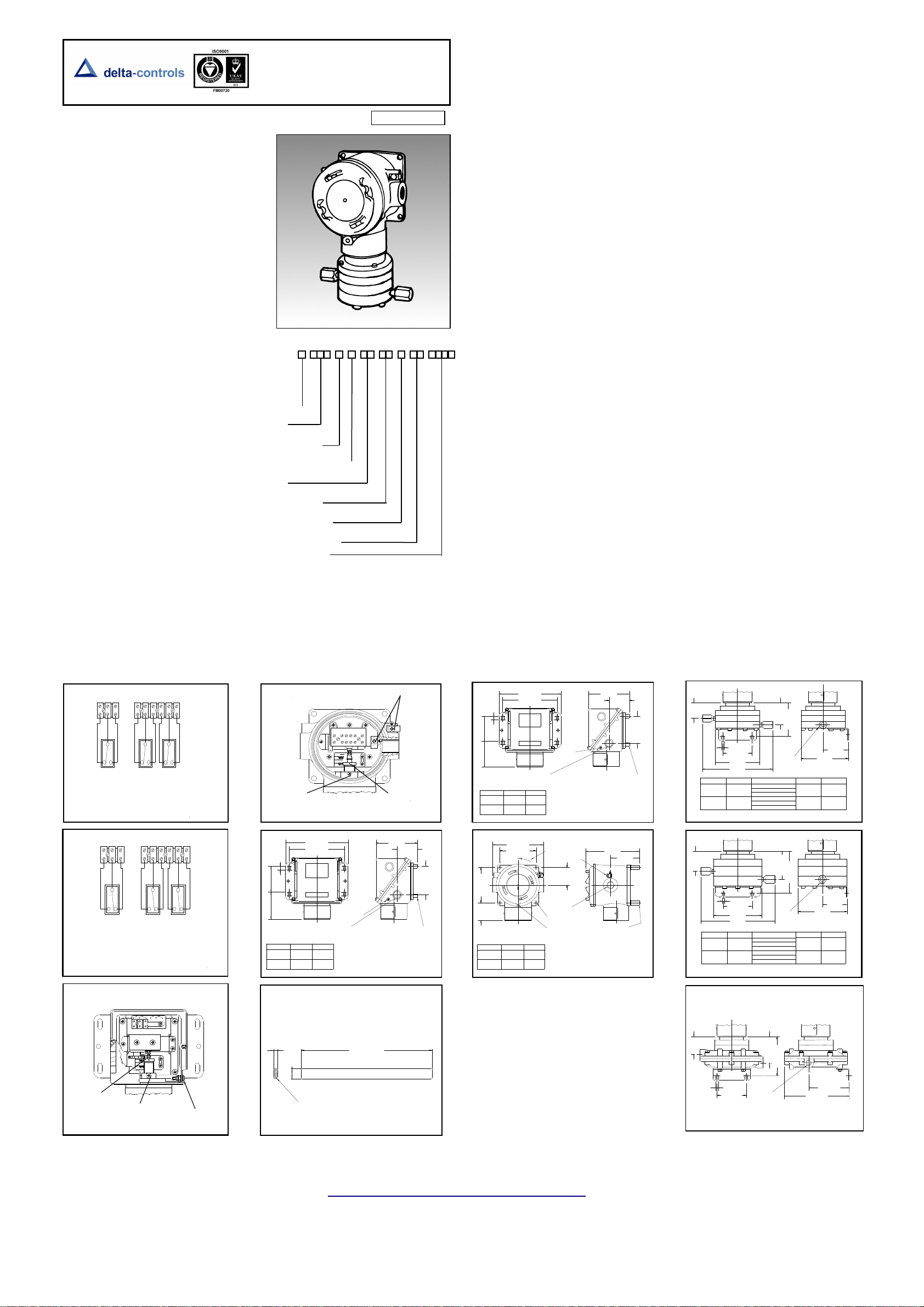
OPERATING PRINCIPLES
A diaphragm is used to sense the difference between
two pressures applied to either side of the diaphragm.
The force is opposed by a control spring, which, at the
point of equilibrium permits movement of an operating
rod that actuates a switch or switches.
INSTALLATION
The instruments are designed to be mounted to a wall
or panel vertically as shown in figs 4, 5, 6, 7, 8, 9 using
the backplates provided. However, mounting up to
45° from the vertical in any plane is acceptable,
although a small calibration shift may occur. Select
the mounting point so as to avoid excessive shock,
vibration or temperature fluctuation. Instruments
should be mounted to avoid excessive heat transfer
from the process lines or adjacent plant. To avoid
undue stresses being imparted to the instrument when
wall / panel mounted, it is recommended that a short
length of flexible line be installed between the
instrument and process line.
If sudden changes of pressure (pulsations) are likely
then we recommend that snubbers are fitted between
the process line and switch.
Use a spanner to support the process connection
when fitting the instrument. DO NOT OVERTIGHTEN. When fitting the instrument lid, make sure
gaskets or ‘O’ rings are in good condition and fitted
correctly.
WARNING: CHECK THE CONNECTION THREAD
SIZE AND SPECIFICATION ON THE UNIT TO AVOID
MIS-MATCHING WITH THE PROCESS
CONNECTION ADAPTOR. SEE DIGIT 11 OF
PRODUCT CODE.
SET POINT
ADJUSTER
FIG 2
SPDT
REAR FRONT
2 x SPDT
NC = NORMALLY CLOSED
COM = COMMON
NO = NORMALLY OPEN
NC
RED
NC = NORMALLY CLOSED
COM = COMMON
NO = NORMALLY OPEN
MA
SET POINT
LOCK
NC
REAR
SWITCH
RED
2 x
SWITCH
EARTH / GROUND
NC
BLUE
FIG 1A
BLUE
FIG 1B
INSTALLATION, OPERATING AND
MAINTENANCE INSTRUCTIONS FOR
DIAPHRAGM ACTUATED SERIES
S30 SOVEREIGN PRESSURE DIFFERENCE
SWITCHES (MODELS S31 & S34)
ISSUE F 02/10
PRODUCT CODE
ENCLOSURE
MODEL
CERTIFIED ENCLOSURES
All series S30 pressure switches can be supplied with
enclosures for use in hazardous areas to the following
standards:
Zone 1 (Div 1) IEC 79-1
BS 5501: Parts 1 and 5: EN50 014 and EN50 018
CENELEC. Codes ‘H’ for aluminium EEx d IIC T6,
and ‘R’ for stainless steel EExd IIC T6.
DIV 1 (NEC 500)
Class I Groups C and D, Class II Groups E, F and G.
Codes ‘T’ for aluminium and ‘U’ for stainless steel.
The above-mentioned enclosures are suitable for
outdoor use rated IP 66 / NEMA 4. Only operation,
maintenance or repair procedures either contained
herein or approved by Delta Controls may be used, to
avoid rendering the equipment unsafe in operation and
/ or nullifying the Certification. NO MODIFICATIONS
ARE PERMITTED.
Japanese Zone 1.
Same as CENELEC Zone 1 IEC 79 with additional
label and alternative terminal arrangement. Code ‘B’
for aluminium IIC T6. Refer to appropriate Japanese
standards for guidance on installation and use.
Electrical Adaptors
Use only certified adaptors for Zone 1/Div 1.
WARNING: IT IS A REQUIREMENT OF SAFETY
THAT AT LEAST 5 FULL THREADS ARE ENGAGED
BETWEEN THE ADAPTOR AND CONDUIT ENTRY.
References for Selection and Installation
BS 5345 Part 3 for Enclosure Codes H and R.
BS 5501 Part 1 for Enclosure Codes H and R.
BS 5490 IEC 529 IP RATING (Ingress Protection)
NEC ARTICLE 500 for Enclosure Code T and U.
MAINTENANCE
Inspections should be carried out at quarterly to yearly
intervals depending upon operating conditions.
Isolate the unit from process and power and remove
the lid. Check all terminals for tightness. Check that
ELECTRICAL ENTRY
MATERIAL OF WETTED PARTS
RANGE
SWITCHING OPTIONS
PROCESS CONNECTION
OPTIONS AND TREATMENTS
SPECIAL ENGINEERING
WIRING Fig 1A Enclosures H, R, T, U, B
WIRING Fig 1B Enclosures A, W
Wire in accordance with local and National codes.
Use cables no larger than 2.5 mm2 (14 AWG). Deliver
electrical connection through a suitable cable gland,
which will maintain the IP rating of the instrument.
Insert bare wires fully into the terminal block and
tighten securely. Keep wiring tails to a minimum and
check that wires do not interfere with the operating
mechanism. Use the earthing points provided.
SET POINT
LOCK
FIG 3
ELECTRICAL ENTRY
MODEL S31/S34
RANGE
DIM A
BD, CB, CE
115 (4.52) 57 (2.24)
DC, DD, EA
103 (4.05)
spanner to open.
11 (0.43)
25 (1)
5.5 (0.21)R
In the interest of development and improvement Delta Controls Ltd, reserve the right to amend without notice,
details contained in this publication. No legal liability will be accepted by Delta Controls Ltd, for any errors,
DELTA CONTROLS LIMITED, ISLAND FARM AVENUE, WEST MOLESEY, SURREY KT8 2UZ
T +44 (0) 208 939 3511 F +44 (0) 208 783 1163 E sales@delta-controls.com W www.delta-controls.com
MIN
MAX
174 (6.85)
154 (6.06)
FIXING CE NTRES
DIM B
45 (1.77)
YOUR TRUSTED PARTNER IN PROCESS INSTRUMENTATION
EARTH / GROUND
COM
COM
IN
SET POINT
ADJUSTER
DIM A
DIM B
SCREW
W ENCLOSURE
DIMENSIO NS FOR G UIDANCE ONLY mm (i nches)
MIN.
350 (13.8)
Fig. 4A
FIG 4
omissions or amendments.
cable tails are not fouled or chafed. Check for internal
condensation. Rectify as necessary.
It is recommended that instruments used to provide an
alarm are operated periodically to ensure they are
functioning correctly.
If further maintenance is required seek advice from
DELTA CONTROLS before attempting repair or
replacement of parts.
CAUTION
Moving parts have been treated with a water repelling
lubricant before leaving the factory. Occasional
inspection and the application of a water repelling
lubricant is recommended to ensure moving parts
remain free under all conditions.
WARNING: DOES NOT APPLY TO OXYGEN
SERVICE.
On enclosures H, R, T, U and B, remove the lid using
an appropriate tool. If tight use edge of a spanner or a
metal rod (fig 4A).
RANGE
BD, CB, CE
DC, DD, EA
RANGE
BD, CB, CE
DC, DD, EA
FIXING C ENTR ES
MODEL S3 1/S 34
DIM A
115 (4.52) 57 (2.24)
103 (4.05)
140 (5.51)
100 (3.93)
FIXING CENTRES
MODEL S31/ S34
DIM A
149 (5.86)
136 (5.35) 67 (2.63)
174 (6.85)
154 (6.06)
SCREW
DIM B
45 (1.77)
DIME NSIO NS FO R GUI DAN CE ONL Y m m (in che s)
ROT AT E TO R EM OVE
ENT RY
8 mm D IA
LO OSE N TO R EMO VE LID
DIM B
80 (3.14)
H, R, T, U ENCLO SURE
DIM EN SI ON S F OR G UIDA NC E ON LY
DIM A
WH EN APPLICABLE)
A ENCLOSURE
FAC ILIT Y
WH EN APP LIC AB LE)
mm (inch es )
DIM B
DIM B
FIG 5
FIG 6
Registered Office Registered in England No 5369683
Zone 1 Enclosure (H, R, T, U, B)
Thread seal and contact surfaces must be lightly
lubricated using a non-setting non-corrosive grease
compatible with the lid seal. Do not use copper
bearing grease. Screw on lid hand tight making sure
that mating surfaces of the lid and enclosure are in
contact. Re-tighten the lid lock screw.
WARNING: IT IS A SAFETY REQUIREMENT THAT
AT LEAST 5 FULL THREADS ARE ENGAGED WHEN
THE UNIT IS IN OPERATION. NEVER OPERATE
THE UNIT UNLESS THIS CONDITION IS MET. DO
NOT USE GREASES OR LUBRICANTS NOT
COMPATIBLE WITH THE ENVIRONMENT OR
PROCESS.
Weather-proof Enclosure (W)
If lid gasket is dried out or damaged, replace with new
greased gasket. Make sure gasket aligns correctly
with sealing faces.
Stainless Steel Weather-proof Enclosure (A)
Check gasket. If damaged, replace.
OPERATION
Pressure difference switches are supplied calibrated
against falling pressure unless otherwise specified.
Set Point adjustment refers to falling pressure.
Switching differential is the difference between the set
point and the operating value on rising pressure. For
opening details see Figs 4, 5, 6.
Set Point Adjustment: Models S31, S34 (Figs 2, 3)
1. Isolate the instrument from process and power.
2. Remove the instrument lid.
3. Slacken the set point lock screw.
4. Rotate the set point adjuster screw as required.
Rotate clockwise to increase the set point and counterclockwise to decrease the set point.
5. Tighten the set point lock screw.
6. Replace the instrument lid (see maintenance).
Note: For accurate setting, a suitable pressure gauge
must be used in conjunction with the above procedure.
Do not attempt to set the switch outside the scale
limits. Though the unit may be set anywhere within its
operation range, for optimum performance, it is good
practice to have a set point value between 25% and
75% of span.
LP
MO D EL S 31
RAN GE
BD , CB , CE
LP
51 (2)
MOD EL S3 4
RANGE
BD, CB , CE
DC, DD , EA
LP
FIX ING CE N TRE S
FIXIN G C EN TRE S
MOD E L S31
HP
7 (0 .27 )
75 (2.9 5)
DIA A
DIM B
DIM A
113 (4 .44 )
88 (3.4 6)
DIM EN SI ON S F OR G UID A NC E O NL Y m m (i nc hes )
179 (7 .04 )
154 (6 .06 )
170 (6 .69 )
DIM B
COD E H
CO DE J
COD E H
COD E J
CON NE C TIO N
COD E A & F
COD E A & F
MODE L S34
HP
7 (0.27)
75 (2.95 )
DIA A
DIM B
DIM A
126 ( 4.96)
100 ( 3.93)
DIME NS ION S FO R G UID AN CE ONL Y m m (inch es)
MODEL S31 RANGE BC
7 (0.27)
75 (2.95)
PRO CESS
CON NEC TIO N
DIM B
192 ( 7.55)
CODE A & F
CODE H
218 (8. 58)
208 (8. 18)
CODE J
CODE A & F
166 (6. 35)
CODE H
192 (7. 55)
CODE J
182 (7. 16)
HP
PROCESS
CONNECTION
DIMENSIONS FOR GUIDANCE ONLY mm (inches)
DIM C
52 (2.0 4)
DIM C
63 (2 .48)
166 (6.53)
DIM D
DIM D
126 (4.96)
103 (4.05)
DIM C
DIM D
121 (4 .76 )
96 (3.7 7)
DIM C
DIM D
102 (4.01)
FIG 8
Stock No: 002522/S31
Page 2
Machinery Safety Directive MSD
– 2006/42/EC
WIRING
Pollution degree
TAB L E A
– MICROSWI TC H R A T I N G S
C O D E
U L / C S A
IEC 9 4 7
-5-
1 / EN 60 9 4 7
-5-
1 RATING
D e s i g n a t i o n
VA
R A T I N G
0 . 6 / 0 . 3 A @
A C 1 4 /
AC 4 3 2
7 2
0 . 8 k V
2 5 0
0 . 2 2 / 0 . 1 A @
D C 1 3 /
D C
2 8 2 8
0 . 6 / 0 . 3 A @
A C 1 4 /
A C
4 3 2 7 2
0 . 8 k V
2 5 0 V
0 . 2 2 / 0 . 1 A @
D C 1 3 /
D C
2 8 2 8
0 4
1 A @ 1
2 5 V A C R E S I S T I V E ( I E C 1 0 5 8
-
1 / E N 6 1 0 5 8
-
1 )
0 . 6 / 0 . 3 A @
A C 1 4 /
A C
4 3 2 7 2
0 . 5 k V
2 5 0 V
0 . 2 2 / 0 . 1 A @
D C 1 3 /
D C
2 8 2 8
0 G
A C 1 4 /
A C
2
1 6 3 6
0 . 5 k V
1 2 5 V
0 . 3 A @ 1 2 0
V A C
0 C
0 . 8 k V
2 5 0 V
0 . 6 / 0 . 3 A @
A C 1 4 /
A C
4 3 2 7 2
0 . 6 / 0 . 3 A @
A C 1 4 /
A C
4 3 2 7 2
0 . 8 k V
2 5 0 V
0 . 2 2 / 0 . 1 A @
D C 1 3 /
D C
2 8 2 8
0 . 6 / 0 . 3 A @
A C 1 4 /
A C
4 3 2 7 2
0 . 5 k V
2 5 0 V
0 . 2 2 / 0 . 1 A @
D C 1 3 /
D C
2 8 2 8
Low Voltage Directive (LVD) – 2006/95/AC. Switch products with enclosure codes ‘W’ and
‘A’ supplied CE-marked must be installed and used in accordance with the main instructions
and this addendum supplied with each product. Products rated lower than 50V ac and 75 V dc
are outside the scope of the LVD, and therefore, do not require CE-marking under this
directive. The LVD does not apply to products with enclosure codes ‘H’, ‘K’, ‘R’, ‘M’, ‘N’ for use
in hazardous areas. Switch products with enclosure codes ‘H’, ‘K’, ‘R’, ‘M’, ‘N’, are covered by
the Explosive Atmospheres Directive ATEX – 94/9/EC and when CE-marked will indicate
compliance with this directive alone. The following directives do not apply to switch products
manufactured by Delta Controls:
Electromagnetic Compatibility EMC – 2004/08/EC
ENCLOSURE ‘W’
Cable Glands and adaptors – If enclosure ‘W’ is supplied with a through hole of 22 mm
blanked with a blind grommet. Discard the grommet and fit a suitable proprietary brass or
nylon M20 cable gland with thread length of 10 mm and locknut. Fit the nylon reducer provided
to the inside and a fibre washer to the outside. See diagram 1.
Alternately, the enclosure may be supplied from the factory with a threaded adaptor ready to
accept the customer’s gland or conduit system.
Alternatives:
i) a metal or nylon adaptor may be used to accommodate other sizes of gland eg NPT, or
conduit system. See diagram 2.
ii) an elbow kit may be supplied to enable the entry to be rotated axially through 90° and
radially through 360°. See diagram 3.
Earthing / grounding – The user must make suitable local earthing arrangements, if required,
to ensure that metal glands are earthed.
An earthing point is provided inside the enclosure. If this is disturbed in any way it must be
reassembled correctly to be an effective earth and prevent ingress. See diagram 4. When
removing the lid slacken the M4 nut first and ensure it is re tightened whenever the lid is
replaced. See diagram 4.1.
ENCLOSURE ‘A’
Cable Glands and adaptors – Enclosure ‘A’ is supplied with an M20 x 1.5 tapped hole. Use a
suitable stainless steel cable gland and sealing washer. Alternately the enclosure may be
supplied with a threaded adaptor fitted at the factory ready to accept the customer’s gland or
conduit system. See diagram 5.
Earthing / grounding – Bonding between the enclosure and gland / adaptor will be achieved
when both parts are screwed together. An earthing point is provided inside the enclosure. If
this is disturbed in any way it must be reassembled correctly to be an effective earth and
prevent ingress. See diagram 4.
EARTHING / GROUNDING OF PROCESS CONNECTION AND BACK PLATES – All the
internal dead metal work is bonded to the enclosure earthing point. Due to requirements of
sealing, the process connection and back plates may be isolated from the earthing point. Do
not, therefore, rely on either for earthing, instead always use the earthing point provided. If
required, the process connection and back plates may be bonded locally. Never use the
process connection or inlet pipe for locally grounding welding equipment unless it is separately
earth bonded.
Declaration of Conformity
We: Delta Controls Ltd
Island Farm Avenue
West Molesey
Surrey, UK
KT8 2UZ
As the manufacturers of the apparatus listed, declare under our sole responsibility that the products listed
below:
Pressure, Pressure Difference, Temperature & Flow switches series “W” or “A”:
201, 202, 203, 281, 204, 207, 208, 209, 231, 232, 233, 234, S21, S22, S24, GR2, GR4, VM2, VM4.
301, 303, 304, 381, 384, 306, 386, 310, 316, S31, S34, GR3, GR6.
721, 731, 771, 722, 732, 772, 723, 733, 773, 781, 734, 774, 741, 742, 743, 744, S71, GR7.
131.
To which this declaration relates are in conformity with the following relevant standards or parts thereof:
EN 60947-1 :1992 Low voltage switch gear and control-gear-general rules.
EN 60947-5-1:1992 Low voltage switch gear and control-gear-control circuit devices and switching
elements.
EN 60529: 1991 Specification for classification of degrees of protection provided by enclosures.
EN 60950:1992 Safety of information technology equipment including electrical business equipment:
section 2.5.
BS 6134:1991 Specification for pressure and vacuum switches.
And thereby conforms to the requirements of the Low Voltage Directive 73/23/EC amended by 93/68/EEC.
………………….
R. Harrison
Managing Director
Original dated 22nd June 2000
Rev. B dated 12
th
August 2009
Signed:
conditions where condensation may readily form, then sealed contacts should be used. See
Table A codes 08/09, 0G/0H, H2/H3/H6.
Electrical isolation – These products are not suitable for electrical isolation. Always isolate
circuit separately to carry out any electrical work.
M I C R O S W I T C H
( R E S I S T I V E )
* S E E N O T E
S W I T C H
5 A @ 1 1 0 / 2 5 0
0 0
&
0 1
5 A @ 1 1 0 / 2 5 0
0 2
&
0 3
2 A @ 3 0 V D C
1 A @ 1 2 5 V A C
&
0 5
* 1 0 0 m A @ 3 0
0 8
0 9
0 H
0 D
H 2
H 3
H 6
1 1 0 / 2 5 0 V A C
&
5 A @ 3 0 V D C
* 1 A @ 3 0 V A C
&
5 A @ 1 1 0 / 2 5 0
5 A @ 1 1 0 / 2 5 0
2 A @ 3 0 V D C
5 A @ 1 1 0 / 2 5 0
&
2 A @ 3 0 V D C
&
The el e c t r i c a l rat i n g is depe nd e n t on th e mi c roswitch fi t t e d to th e
instrume nt. T h e electric al ra t i ng is de f i n e d by each ap p r o v a l t hat
the mic r o s w i t c h c om plies wi t h a n d is shown o n t h e pr o duct
nameplate, i e U L / CSA, or IE C. It s h o u l d b e n o t e d t ha t t he s wi tch
must b e u s ed wit hi n t h e elect r i c a l rating s p e c i f i e d from t h e approv al
you r e q u i r e . Tabl e A lists t h e ac t ua l IE C r a t i ngs aga i nst t he
Designati on & Utilis at i o n Cat egory m a r k e d on t h e nameplate. In t he
absence of a n y v e r i f i c a t ion by UL / CSA t h e m i c r o s wi t c h
*m anufactu r e r ’ s rating i s s pecified i n b o ld i t a l i c s . If i n d o ubt, seek
guidance f r o m f a c t o r y.
– all products are suitable for use in pollution degree 3. For extreme
R A T I N G
V A C
V A C
V D C
* 5 A @
& 3 0 V D C
V A C
V A C
V A C
( I e I U e )
Uimp
Ui
V
1 2 0 / 2 4 0 V A C
1 2 5 / 2 5 0 V D C
1 2 0 / 2 4 0 V A C
1 2 5 / 2 5 0 V D C
1 2 0 / 2 4 0 V A C
1 2 5 / 2 5 0 V D C
1 2 0 / 2 4 0
V A C
1 2 0 / 2 4 0 V A C
1 2 5 / 2 5 0 V D C
1 2 0 / 2 4 0 V A C
1 2 5 / 2 5 0 V D C
&
U t i l i s a t i o n
C a t e g o r y
D 3 0 0
R 3 0 0
D 3 0 0
R 3 0 0
D 3 0 0
R 3 0 0
E 1 5 0
D 3 0 0
D 3 0 0
R 3 0 0
D 3 0 0
R 3 0 0
Make
Break
 Loading...