

Page 1
PPM R1E
Operation Manual
www.deltaww.com
Page 2

Page 3

05
05
06
07
08
09
10
10
11
11
12
13
14
15
16
17
17
18
18
19
19
20
21
22
22
23
24
25
26
26
27
Table of Contents
1 Product introduction
1.1 Product appearance
1.2 Connector setup
1.3 Wall mount
1.4 System diagram
2 Hardware Specifications
3 Function description
3.1 Home page
3.2 Check power generation
3.2.1 Check current power output
3.2.2 Check hourly power generation
3.2.3 Check daily power generation
3.2.4 Check monthly power generation
3.2.5 Check yearly power generation
3.2.6 Check accumulated power generation
3.3 Check single inverter power generation
3.3.1 Check single inverter current power generation
3.3.2 Check single inverter power generation today
3.3.3 Check single inverter daily power generation
3.3.4 Check single inverter monthly power generation
3.3.5 Check single inverter yearly power generation
3.3.6 Check single inverter accumulated power generation
3.4 Check error event
3.5 Setting
3.5.1 Time adjustment
3.5.2 Search device
3.6 Information
3.7 Zero Export
4 Trouble shooting
4.1 No connection to inverter
4.2 Error event
. . . . . . . . . . . . . . . . . . . . . . . . . . . .
. . . . . . . . . . . . . . . . . . . . . . . . . . . . . .
. . . . . . . . . . . . . . . . . . . . . . . . . . . . . . . . .
. . . . . . . . . . . . . . . . . . . . . . . . . . . . . .
. . . . .
. . . . . . . . . . . . . . . . . . . . . . . . . . . .
. . . . . . . . . . . . . . . . . . . . . . . . . .
. . . . . . . . . . . . . . . . . . . . . . . . .
. . . . . . . . . . . . . . . . . . . . . . .
. . . . . . . . . . . . . . . . . . . . . . . .
. . . . . . . . . . . . . . . . . . . . . .
. . . . . . . . . . . . . . . . . . . . . . .
. . . . . . . . . . . . . . . . . . .
. . . . . . . . . . . . . .
. . . .
. . . . . . . . . . . . . . .
. . . . . . . . . . . . . . . .
. . . . . . . . . . . . . . . .
. . . . . . . . . . . . . .
. . . . . . . . . . . . . . .
. . . . . . . . . . . .
. . . . . . . . . . . . . . . . . . . . . . . . . . . . . .
. . . . . . . . . . . . . . . . . . . . . . . . . . . . . .
. . . . . . . . . . . . . . . . . . . . . . . . . . . . . . .
. . . . . . . . . . . . . . . . . . . . . .
. . . . . . . . . . .
. . . . . . . . . . . . . . . . . . . . . . . . . . . . . . . . .
. . . . . . . . . . . . . . . . . . . . . . . . . .
. . . . . . . . . . . . . . . . . . . . . . . . . . . . . . . . .
. . . . . . . . . . . . . . . . . . . . . . . . . . . . . . . . . . .
. . . . . . . . . . . . . . . . . . . . . . . . . . . . . . .
. . . . . . . . . . . . . . . . . . . . . . . . . . . .
. . . . . .
. . . . . . . . . . . . . . . . . . . . . . . . .
. . . . . . . . . . . . . . . . . . . . . . . . . . . . . . . . .
3
Page 4
4
Safety Instructions
DANGER!
- Do not work on electrical installation when standing on wet ground.
- Power monitor is a precision electronics. Please handle with care!
- Do not use product if insulation of any wire is broken.
WARNING !
- Do not open this product or insert tools due to shock and fire hazard
which may cause injury.
- When installing this product you must adhere to the following instructions:
● Do not power up the device before installation is complete.
● All circuit breakers must be in the OFF position before commencing
installation.
- Unsuitable installation locations which will void the product warranty:
● Do not install in direct sunlight.
● Do not expose to high humidity.
● Install in a safe place where it is inaccessible for children.
● Do not install in poorly ventilated area.
● Do not expose to water vapor, oil vapor, smoke, dust, salt, corrosive
substances, explosive / flammable GAS, chemicals.
● Do not install above 1000m mean sea level.
● Do not expose to extreme temperature fluctuation.
● Do not expose to high levels of noise, electrical noise.
● Do not expose to vibration.
● Not suitable for installation in medical equipment, communication
equipment, marine, automotive.
Page 5

1 Product introduction
1.1 Product appearance
● Power monitor
● Connector
ENT
Power Monitor
120.0
115.0
21.3
Product introduction
5
Page 6
or
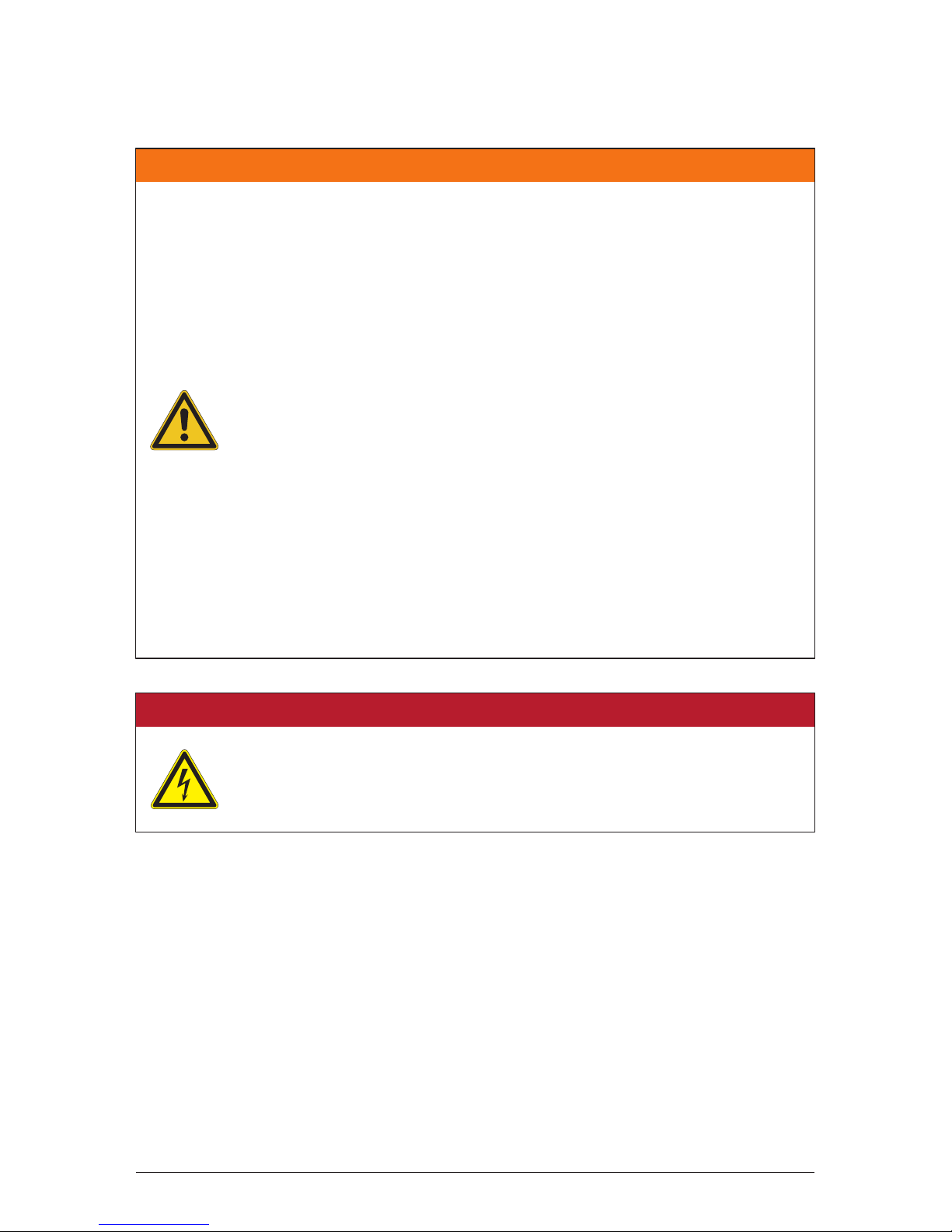
+12V
GND
RS485-A
RS485-B
1.2 Connector setup
Inverter Connector
RS-485 Cable
Terminal Switch
ON
1
6
Product introduction
Page 7
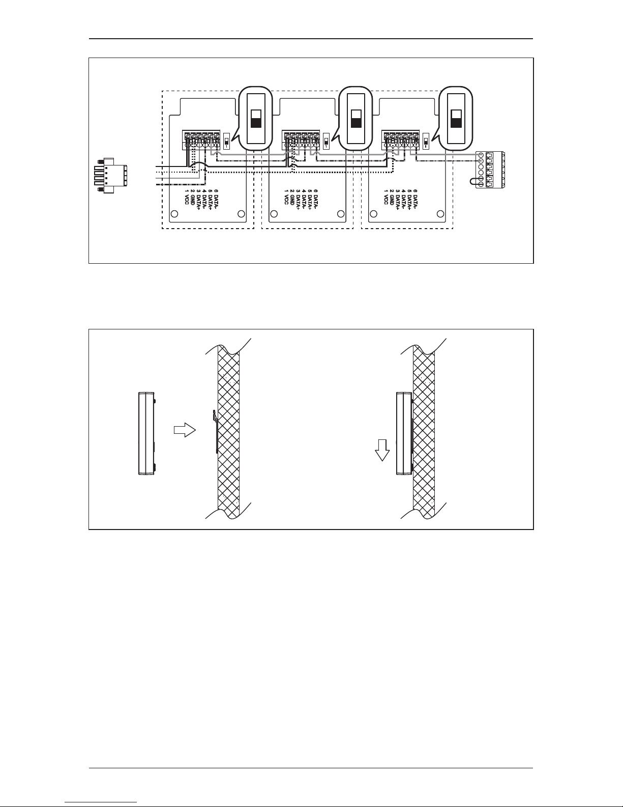
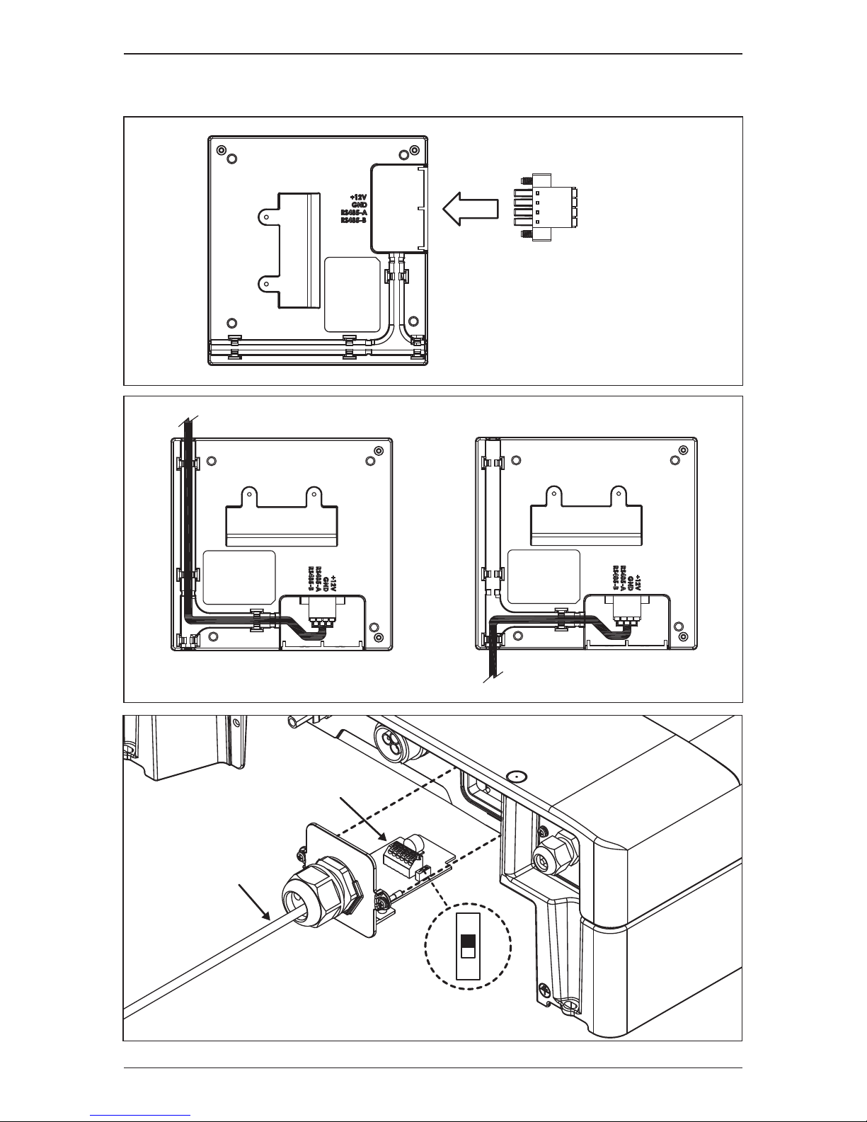
1.3 Wall mount
Terminal
resistance
port short
P1E
Connector
485 A+
485 B485 A+
485 B-
TERM.
ON ON ON
R1E
Connector
ON
1
ON
1
+12V
GND
RS485-A
RS485-B
ON
1
7
Product introduction
Page 8
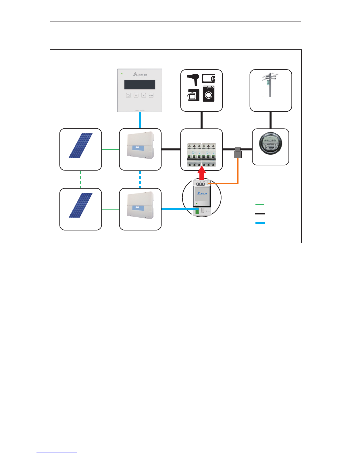
1.4 System diagram
PV Panel
PV Panel
R1E
P1E
AC
DC
RS-485
Electricity
Company
CT
Distribution
panel box
Load
Meter
Inv.No 1
Inv.No 12
8
Product introduction
Page 9

2 Hardware Specifications
Category
HW spec
Regulatory
Information
Communication
Connection
Environment
Dimension
Description
12Vdc
12Vdc ~ 16Vdc
< 1 Watt
EN 62109-2
CE compliance
EN 55022 class B
EN 61000-6-2
Inverter no output power
Inverter generating power
Communication error
between Inverter
Inverter Error / Fault
Today energy
Day / Month / Year energy log
Setting
Power limit
Delta Protocol
4 pin terminal block for RS-485
-20℃ ~ 50℃
-20℃ ~ 60℃
30% ~ 85%
115 mm
120 mm
21.3 mm
160 g
Item
Rated Operating voltage
Operating voltage range
Power Consumption
Safety Standard
Emission
Immunity
Green LED Flash
Green LED On
Red LED Flash
LED
Indicator
Red LED On
LCD Display
RS-485 Communication
Wired
Operation temperature
Storage temperature
Relative humidity
Height
Width
Depth
Weight
9
Hardware Specifications
Page 10

3 Function description
3.1 Home page
Home page screen shown as below:
Date and time
Automatically switches the screen every
three seconds
ItemIndex Description
①
Status Inverter connected
When there are 0-12 inverter connected
Power generated today, unit: kWh
Power purchased today, unit: kWh
②
Number of
inverter connected
③
Power generation
Power purchased
④
⑤
Power consumption Power consumed today, unit: kWh
⑥
Basic operations:
Press any key to enter menu page
to choose an enter page
back to the previous page
Arrow keys to move up and down
15/11/03
14 27 13 kWh
Inv. 1
① ②
⑤④
③
⑥
18 : 00
14 27 13 kWh
Inv. 1
① ②
⑤④
③
⑥
10
Function description
Page 11

3.2 Check power generation
From menu page enter[Energy Log]
From [Energy Log] to enter [Current Power]
Current power screen is shown as below:
Energy Log
Setting
Information
►
Current Power
Hourly
Daily
►
3.2.1 Check current power output
Current time
ItemIndex Description
Status Inverter connected
The number of inverter which are connected
( 0 – 12)
Current power generated, unit: kW
Current power purchased, unit: kW
Number of
inverter connected
Power generation
Power purchased
Power consumption Current power consumed, unit: kW
①
②
③
④
⑤
⑥
09 : 58
1.50 3.00 1.50 kWh
Inv. 1
① ②
⑤④
③
⑥
11
Function description
Page 12

3.2.2 Check hourly power generation
The number of inverter which are connected (0 – 12) From [Energy Log] enter
[Hourly]
Hourly power generation screen shot is shown as below:
Time
ItemIndex Description
Status Inverter connected
The number of inverter which are connected
( 0 – 12)
Hourly power generated, unit: kWh
Hourly power purchased, unit: kWh
Number of
inverter connected
Power generation
Power purchased
Power consumption Hourly power consumed, unit: kWh
Arrow keys to go up or down to check data in
a different time
①
②
③
④
⑤
⑥
06 : 00
1 2 1 kWh
Inv. 1
① ②
⑤④
③
⑥
18 : 00
2 5 3 kWh
Inv. 1
① ②
⑤④
③
⑥
Current Power
Hourly
Daily
►
12
Function description
Page 13

3.2.3 Check daily power generation
Use [Energy Log] to enter [Daily]
Daily power generation screen is shown as below:
You can view data of the recent 31 days (including today)
Date
ItemIndex Description
Status Inverter connected
The number of inverter which are connected
( 0 – 12)
Daily power generated, unit: kWh
Daily power purchased, unit: kWh
Number of
inverter connected
Power generation
Power purchased
Power consumption Daily power consumed, unit: kWh
Click on up or down key to check data in
a different day
①
②
③
④
⑤
⑥
Today
20 33 13 kWh
Inv. 1
① ②
⑤④
③
⑥
Oct. 29
26 41 15 kWh
Inv. 1
① ②
⑤④
③
⑥
Current Power
Hourly
Daily
►
13
Function description
Page 14

3.2.4 Check monthly power generation
Use [Energy Log] to enter [Monthly]
Monthly
Yearly
Total
►
Monthly power generation screen is shown as below:
You can view data for the past 12 months (including this month).
Month
ItemIndex Description
Status Inverter connected
The number of inverter which are connected
( 0 – 12)
Monthly power generated, unit: kWh
Monthly power purchased, unit: kWh
Number of
inverter connected
Power generation
Power purchased
Power consumption Monthly power consumed, unit: kWh
Click on up or down key to check data in
a different month
①
②
③
④
⑤
⑥
Nov. 2015
406 1066 760 kWh
Inv. 1
① ②
⑤④
③
⑥
Dec. 2014
677 1109 432 kWh
Inv. 1
① ②
⑤④
③
⑥
14
Function description
Page 15

3.2.5 Check yearly power generation
Use [Energy Log] to enter [Yearly]
Yearly power generation screen is shown as below:
You can view data for the past 20 years (including this year).
Year
ItemIndex Description
Status Inverter connected
The number of inverter which are connected
( 0 – 12)
Yearly power generated, unit: kWh
Yearly power purchased, unit: kWh
Number of
inverter connected
Power generation
Power purchased
Power consumption Yearly power consumed, unit: kWh
Click on up or down key to check data in
a different year
①
②
③
④
⑤
⑥
2015
4770 6153 1383 kWh
Inv. 1
① ②
⑤④
③
⑥
1996
4474 5097 623 kWh
Inv. 1
① ②
⑤④
③
⑥
Monthly
Yearly
Total
►
15
Function description
Page 16

3.2.6 Check accumulated power generation
Use [Energy Log] to enter [Total]
Accumulated power generation screen is shown as below:
Total
ItemIndex Description
Status Inverter connected
The number of inverter which are connected
( 0 – 12)
Accumulated power generated, unit: kWh
Accumulated power purchased, unit: kWh
Number of
inverter connected
Power generation
Power purchased
Power consumption Accumulated power consumed, unit: kWh
①
②
③
④
⑤
⑥
Total
123456 691346 567890 kWh
Inv. 1
① ②
⑤④
③
⑥
Monthly
Yearly
Total
►
16
Function description
Page 17

3.3 Check single inverter power generation
Use Menu page to enter [Energy Log]
The display of a single inverter’s current power output is shown as below:
You can choose ID to enter and check single inverter power generation, when
ID turns reverse type it is connected.
Move to choose ID, to enter
Energy Log
Setting
Information
►
Then enter [Inverter Log]
Event Log
Inverter Log
►
3.3.1
Check single inverter current power generation
ID 1
1.23 kW
11 : 22
①
③
②
Inverter ID
ItemIndex Description
Current time
Current power generated, unit: kWPower generation
①
②
③
2 3 4 5 61
8 9 10 11 127
17
Function description
Page 18

3.3.2
Check single inverter power generation today
The display of a single inverter’s hourly power produced is shown as below:
You can view data for the past 31 days (including today).
Single inverter daily power generation screen is shown as below:
3.3.3
Check single inverter daily power generation
ID 1
26 kWh
Oct. 29
①
③
②
ID 1
7 kWh
11 : 00
①
③
②
Inverter ID
ItemIndex Description
Time
Hourly power generated, unit: kWh
Press the up or down key to check data in a
different time
Power generation
①
②
③
Inverter ID
ItemIndex Description
Date
Daily power generated, unit: kWh
Press on up or down key to check data in a
different day
Power generation
①
②
③
18
Function description
Page 19

3.3.4
Check single inverter monthly power generation
You can view data for the past 12 months (including this month).
Single inverter monthly power generation screen is shown as below:
You can view data for the past 20 years (including this year).
Single inverter years power generation screen is shown as below:
3.3.5
Check single inverter yearly power generation
ID 1
3954 kWh
2015
①
③
②
ID 1
946 kWh
Nov. 2015
①
③
②
Inverter ID
ItemIndex Description
Month
Monthly power generated, unit: kWh
Press the up or down key to check data in a
different month
Power generation
①
②
③
Inverter ID
ItemIndex Description
Year
Yearly power generated, unit: kWh
Press the up or down key to check data in a
different year
Power generation
①
②
③
19
Function description
Page 20

3.3.6
Check single inverter accumulated power generation
Single inverter accumulated power generation screen is shown as below:
ID 1
50094 kWh
Total
①
③
②
Inverter ID
ItemIndex Description
Total
The total power generated from the start of
the inverter, unit: kWh
Power generation
①
②
③
20
Function description
Page 21

3.4 Check error event
When an error event occurs, the icon below will appear on the Home page:
Energy Log
Setting
Information
►
Then enter [Event log]
Use Menu page to enter [Energy Log]
Event Log
Inverter Log
►
1. No error event screen is shown as below:
EMPTY
2. With error event screen is shown as below:
2015/10/18 17:30 ID1 11
2015/10/21 12:30 ID5 10
2015/10/25 08:30 ID6 01
►
Choose error event to check data
11
Temp High
18 : 00
14 27 13 kWh
Inv. 1
21
Function description
Page 22

3.5 Setting
Use menu page to enter [Setting]
Time Adjustment
Search Device
►
Warning:
Adjustment could affect
energy record.
2015
01 M 28 D
13 h 50 m
2015
01 M 28 D
13 h 50 m
2015
01 M 28 D
13 h 50 m
2015
01 M 28 D
13 h 50 m
2015
01 M 28 D
13 h 50 m
Enter [Time Adjustment]
Warning: Time adjustment will affect the power generation record.
Click on enter key again to enter time adjustment page, and adjust year, month,
day, hour and minute in order.
Operation: to change value, to confirm.
3.5.1 Time adjustment
22
Function description
Page 23

3.5.2 Search device
Enter [Inverter number] to set up search inverter quantity.
Enter [Ready to search?] and inverter search will start immediately;
quantity of inverter connected will show up after 3 seconds.
Inverter number : 5
Ready to search ?
►
Inverter number : 5
Searching... Found inverter : 5
Operation: to change value, to confirm.
23
Function description
Page 24

3.6 Information
Use Menu page to enter [Information]
You can choose ID to enter and check information, when ID turns into reverse
type, it is connected.
ID1 ~ 12 is inverter, M is Meter, R is Remote Control.
Enter inverter screen shown as below:
Energy Log
Setting
Information
►
DSP : 1.05
RED : 1.07
COMM : 1.06
Enter M screen shown as below:
METER : 1.03
Enter R screen shown as below:
RC : 1.07
2 3 4 5 61
8 9 10 11 127
RM
24
Function description
Page 25

3.7 Zero Export
Zero Export aims to make the total inverter power generation close to total power
consumption to avoid the over generated power flowing back to the city grid.
It can be done through the following steps.
Through RS-485 and Meter communications, RC reads the current total power
generation of inverter and the difference between power generation and
consumption. It also reads single generation by communicates with inverter.
Calculate inverter target total power generation via Zero Export algorithm, and
then assign the total generating capacity to the connected inverter to instantly
control a single inverter generation through RS-485.
When power consumption increases, power generation will also increase;
when power consumption is reduced, power generation will also be reduced.
The following icon appears when power de-rating:
18 : 00
14 27 13 kWh
Inv. 1
Use Menu page enter [Power Limit], you can check single inverter target power
generation.
ID1 50%
ID2 50%
ID3 51%
ID4 51%
ID5 50%
ID6 51%
If there are more than 6 inverter connected, you can press to show
the next page.
You can enter [Moment Power] to check current power change.
ID7 50%
ID8 50%
ID9 51%
ID10 51%
ID11 50%
ID12 51%
25
Function description
Page 26

4 Trouble shooting
4.1 No connection to inverter
If the icon below appears on home page, please run the following steps and
search inverter again.
1. Click on any key on home page to enter menu page, enter [Setting], then
enter [Search Device]
2. Choose [Inverter number] to set up search inverter quantity, to
change value, to confirm.
3. Choose [Ready to search?] to start search inverter, quantity of inverter
connected will show up after 3 seconds.
18 : 00
0 0 0 kWh
Inv. 0
Energy Log
Setting
Information
►
Time Adjustment
Search Device
►
Inverter number : 5
Ready to search ?
►
Inverter number : 5
Searching... Found inverter : 5
26
Trouble shooting
Page 27

4.2 Error event
When error event occurs, the icon below will appear on the Home page:
18 : 00
14 27 13 kWh
Inv. 1
Error event definition:
Event
1
5
6
7
8
9
10
11
13
14
15
16
17
18
19
20
21
22
23
24
25
27
28
29
30
Description
DC Injection
NTC Over Temperature
NTC0 Circuit Fail
NTC Low Temperature
Heat Sink Ntc1 Circuit Fail
Heat Sink Ntc2 Circuit Fail
Heat Sink Ntc3 Circuit Fail
Inverter Choke Over Temperature
Relay Open
Firmware Incompatibility
DSP ADC Vgrid/Iout Bias Fail
ADC Vin/Vbus Bias Fail
ADC Iin/Iboost Bias Fail
Red. ADC Vgrid Bias Fail
ADC Iout_dc Bias Fail
Efficiency Abnormal
Fan Fail
Internal Communication Fault (between Redundant)
Internal Communication Fault (between Display)
Residual Current Over Rating
Insulation
RCMU Circuit Fail
Relay Test Short
Relay Test Open
Bus Unbalance
27
Trouble shooting
Page 28

31
32
33
34
35
36
37
42
43
44
45
46
50
60
61
70
71
74
129
130
134
135
136
137
138
139
140
141
153
158
159
162
209
210
212
213
215
219
223
Bus P Over Voltage Rating
Bus P Under Voltage Rating
Bus N Over Voltage Rating
Bus N Under Voltage Rating
Bus Voltage Over Rating
Output Current Transient Over Rating
Output Current Over Rating
CT current sensor Fail (A)
CT current sensor Fail (B)
CT current sensor Fail (C)
HW OOCP Circuit
Inverter Failure
Zero Cross Circuit Fail
PV1 Current Over Rating
PV2 Current Over Rating
PV1 Current Transient Over Rating
PV2 Current Transient Over Rating
External Communication Fail
Over Frequency Range
Under Frequency Range
Phase Jump
Grid Quality
Ac Connected Fail
No Grid
Under Voltage Range
Over Voltage Range
Over Transient Voltage Range
Slow Over Voltage Range
EPO
PV input voltage too high
PV input voltage too high
Insulation
Solar1 UVR
Solar2 UVR
PID Relay Fail
PID Over Current Range
De-rating
Fan Fail
SPD
28
Trouble shooting
Page 29

Page 30

Version 1.01 | 2015 | Dec.
5013236100
 Loading...