

Page 1
Instruction Manual
PMH series
1. Safety Instructions
• To ensure sucient convection cooling, always maintain a safety distance of ≥ 20mm from all ventilated surfaces while the device is in operation.
• For PMH-100WCL□□, PMH-100WCM□ and PMH-150WCL□ models, always maintain a safety distance of ≥ 50mm from all four sides
while the device is in operation. The cover's top ventilated surface must be kept free from any obstructions.
• The device is not recommended to be placed on low thermal conductive surface, for example, plastics.
• Note that the enclosure of the device can become very hot depending on the ambient temperature and load of the power supply. Do not
touch the device while it is in operation or immediately after power is turned OFF. Risk of burning!
• Do not touch the terminals while power is being supplied. Risk of electric shock.
• Prevent any foreign metal, particles or conductors to enter the device through the openings during installation. It can cause: Electric shock;
Safety Hazard; Fire; Product failure
• The appliance is not to be used by persons (including children) with reduced physical, sensory or mental capabilities, or lack of experience
and knowledge, unless they have been given supervision or instruction.
• The power supply must be mounted by metal screws onto a grounded metal surface.
• Warning: When connecting the device, secure Earth connection before connecting L and N. When disconnecting the device, remove L and
N connections before removing the Earth connection.
• The device is earthed and must be inaccessible.
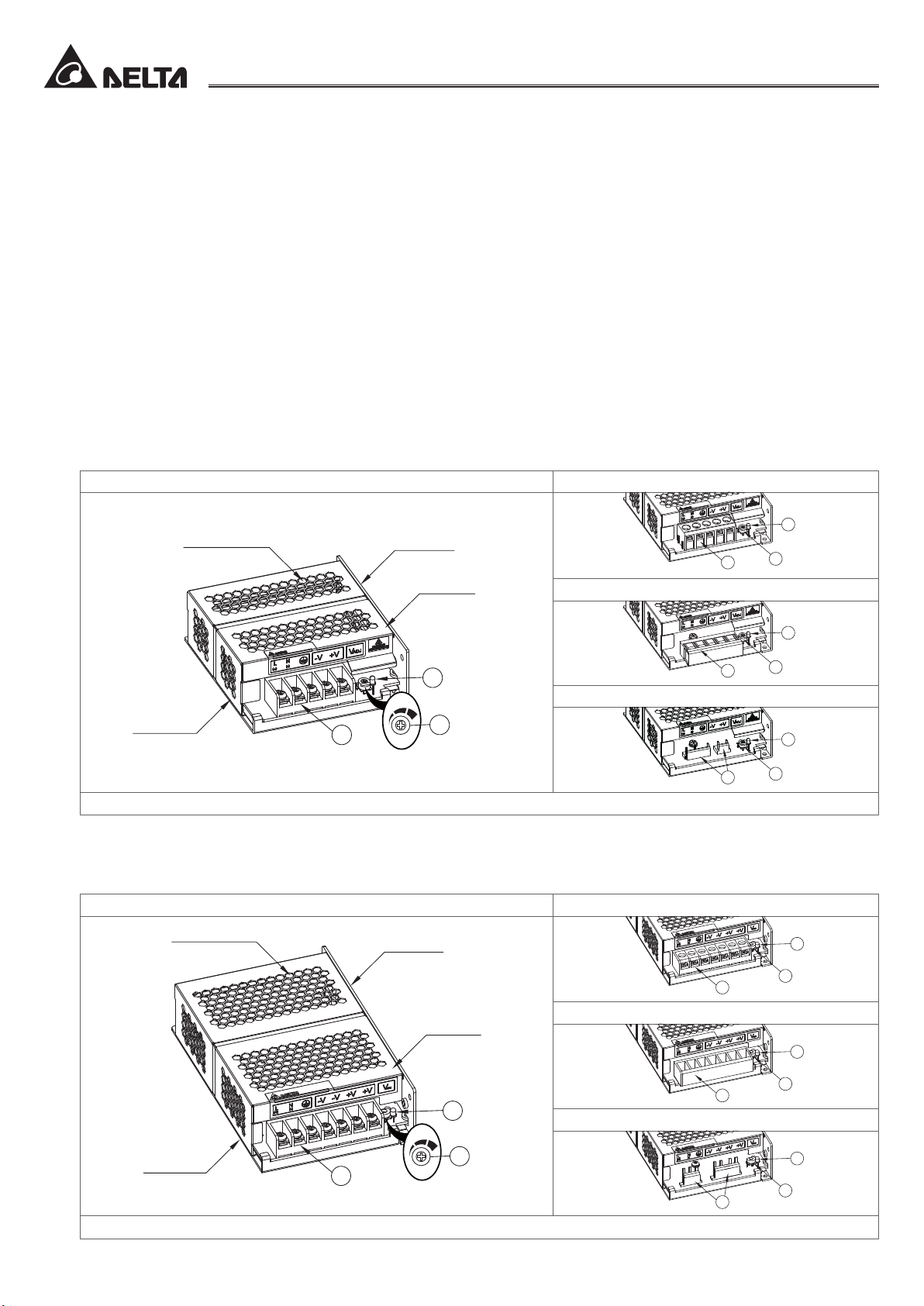
2. Device Descriptions
► PMH-50WCA□ (Refer to Fig. 1.1)
䐟 Input & Output connector
䐠 DC voltage adjustment potentiometer
䐡 DC OK control LED (Green)
Terminal Block IP20 Connector
3
Ventilated surface
Side surface
Top surface
3
1
Front Face Connector
1
2
3
2
Harness Connector
Base surface
*Please note that all images are for illustrative purposes only, and do not necessarily represent the exact products.
1
2
1
3
2
Fig. 1.1. Device Descriptions
► PMH-100WCA□, PMH-100WCC□, PMH-100WCN□, PMH-150WCA□, PMH-150WCD□, PMH-200WC□□ (Refer to Fig. 1.2)
䐟 Input & Output connector
䐠 DC voltage adjustment potentiometer
䐡 DC OK control LED (Green)
Terminal Block IP20 Connector
Ventilated surface
Side surface
3
1
2
Front Face Connector
Top surface
3
2
3
2
3
Base surface
*Please note that all images are for illustrative purposes only, and do not necessarily represent the exact products.
1
2
1
Harness Connector
1
Fig. 1.2. Device Descriptions
www.DeltaPSU.com REV.05
Page 2
A
C
B
B
C
A
B
C
A
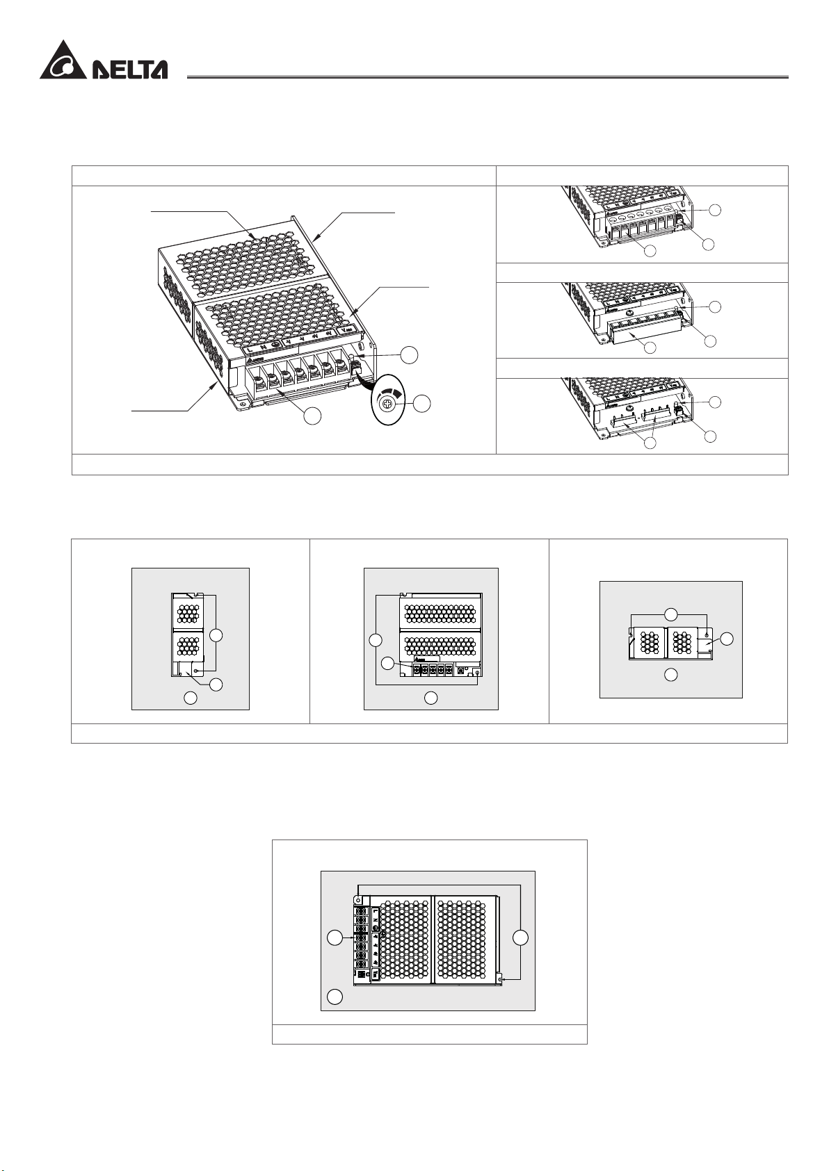
► PMH-100WCL□□, PMH-100WCM□, PMH-150WCL□ (Refer to Fig. 1.3)
䐟 Input & Output connector
䐠 DC voltage adjustment potentiometer
䐡 DC OK control LED (Green)
Terminal Block IP20 Connector
Instruction Manual
PMH series
Ventilated surface
Side surface
Top surface
3
1
2
Front Face Connector
3
3
1
2
Harness Connector
Base surface
1
*Please note that all images are for illustrative purposes only, and do not necessarily represent the exact products.
2
1
3
2
Fig. 1.3. Device Descriptions
3. Installation of the Device
► PMH-50WCA□, PMH-100WCA□, PMH-100WCC□, PMH-100WCN□, PMH-150WCA□, PMH-150WCD□, PMH-200WC□□ (Refer to
Fig. 2.1)
Side Mounting (Vertical) Base Mounting (Vertical) Side Mounting (Horizontal)
A
A
C
B
A
C
B
B
C
Fig. 2.1. Mounting Orientations
䑵 Mounting holes for power supply assembly onto the mounting surface. The power supply shall be mounted on minimum 2 mounting
holes using M3 screw minimum 5mm length.
䑶 This surface belongs to customer’s end system or panel where the power supply is mounted.
䑷 Connector
► PMH-100WCL□□, PMH-100WCM□, PMH-150WCL□ (Refer to Fig. 2.2)
Base Mounting (Vertical)
C
B
A
Fig. 2.2. Mounting Orientations
䑵 Mounting holes for power supply assembly onto the mounting surface. The power supply shall be mounted on minimum 2 mounting
holes using M3 screw minimum 5mm length.
䑶 This surface belongs to customer’s end system or panel where the power supply is mounted.
䑷 Connector
www.DeltaPSU.com REV.05
Page 3

4. Connection
Connector
Type
Terminal
Block
IP20
Connector
Front Face
Connector
Harness
Connector
Notes:
(1) The torque at the Connector shall not exceed 13 Kgf.cm. The insulation stripping length should not exceed 0.275" or 7mm (Refer to Fig. 3).
(1)
(1)
(1)
Specications
Stranded or Solid
Wire Size
Stranded or Solid
Wire Size
Stranded or Solid
Wire Size
Input
(CN1)
Output
(CN2)
JST
JST
Header
(Board
Mounting)
Mating
Connector
Terminal SVH-21T-P1.1
Header
(Board
Mounting)
Mating
Connector
Terminal SVH-21T-P1.1
12V 24V
100WC□□□ 50WCA□ 100WCA□ 100WCC□ 100WCL□ 100WCM□ 100WCN□ 150WCB□ 150WCD□ 150WCL□ 200WC□□
AWG 20-14
AWG 20-12
AWG 20-12
B3P(6-2.3.5)-VH(LF)(SN)
VHR-6N
AWG 20-18
B4P7-
VH(LF)(SN)
VHR-7N VHR-3N VHR-7N
AWG 20-18
B2P3-VH
(LF)(SN)
B4P7-VH(LF)(SN)
Instruction Manual
PMH series
7mm
Stripped WireLug
Fig. 3. Wire Type
5. Installation of Mounting Accessories (Refer to Fig. 4)
• Only use the recommended screw size, length and mounting tightening torque for the base mounting holes. This is to keep a safety
distance between the screw and internal components.
Specications
Screw Size Metric M3
Max. Protrusion Screw Length mm 3.5 6 3.5 6 3.5 5
Mounting Tightening Torque Kgf.cm 4~8
12V 24V
100WC□□□ 50WCA□ 100WCA□ 100WCC□ 100WCL□ 100WCM□ 100WCN□ 150WCB□ 150WCD□ 150WCL□ 200WC□□
Mounting
accessories
Chassis of
the device
Mounting
screw
Max. Length
Fig. 4. Mounting Screw
Manufacturer:
Delta Electronics (Thailand) PCL.
909 Pattana 1 Rd., Muang,
Samutprakarn, 10280 Thailand
Authorized Representative:
Delta Greentech (Netherlands) B.V.
Zandsteen 15, 2132 MZ Hoofddorp,
The Netherlands
www.DeltaPSU.com REV.05
 Loading...