

Delta Performance PG-25, Performance PG-30, Performance PG-35, Performance PG-40, Performance PG-45 Installation And Maintenance Manual
Page 1

Warranty Registration Card must be filled out by the customer and mailed within thirty (30) days of installation in order to gain warranty coverage.
When receiving the Delta Performance unit, any claims for damage or shortage in shipment must be filed
immediately against the transportation company by the consignee.
Leave all documentation received with appliance with owner for future reference.
WARNING
* I N S
* I N S TTAALLLLAATT
I O N
I O N AA
N D M
N D M AA
I N
I N TT
E N
E N AA
N C E *
N C E *
M
M AA
N U
N U AALL
- Input from 100,000 to 199,000 Btu/hr -
NOTICE
If the information in this manual is not followed exactly, a fire or explosion may
result causing property damage, personal injury or death.
FOR
YOUR SAFETY
• Do not store or use gasoline or other flammable vapors and liquids in the vicinity of
this or any other appliance.
• WHAT TO DO IF YOU SMELL GAS
- Do not try to light any appliance
- Do not touch any electrical switch; do not use any phone in your building.
- Immediately call your gas supplier from a neighbor’s phone. Follow the gas
supplier’s instructions.
- If you cannot reach your gas supplier, call the fire department.
Installation and service must be performed by a qualified installer, service agency or the
gas supplier.
PG-25/30/35/40 & 45
Gas Fired
Combination Heaters
Category I or Category III
Vented Appliance
The
CONFORMS TO
ANSI Z 21-10-3
CERTIFIED TO
CGA CAN 1-4-3 M85
90870
Page 2

Page 3

Table of Contents
i
PRODUCT AND SAFETY INFORMATION
Definitions . . . . . . . . . . . . . . . . . . . . . . . . . . . . . . . . . . . . . . . . . . . . . . . . 1
Product Warnings . . . . . . . . . . . . . . . . . . . . . . . . . . . . . . . . . . . . . . . . . . . 2-3
Operating Restrictions . . . . . . . . . . . . . . . . . . . . . . . . . . . . . . . . . . . . . . . 4
Code Restrictions . . . . . . . . . . . . . . . . . . . . . . . . . . . . . . . . . . . . . . . . . . . 4
SECTION I - PRE-INSTALLATION ITEMS
Code Compliance . . . . . . . . . . . . . . . . . . . . . . . . . . . . . . . . . . . . . . . . . . . 5
Determining Product Location . . . . . . . . . . . . . . . . . . . . . . . . . . . . . . . . . 5
Boiler Replacement . . . . . . . . . . . . . . . . . . . . . . . . . . . . . . . . . . . . . . . . . 5
Recommended Clearances . . . . . . . . . . . . . . . . . . . . . . . . . . . . . . . . . . . . 5-6
Flooring and Foundation. . . . . . . . . . . . . . . . . . . . . . . . . . . . . . . . . . . . . . 6
Residential Garage Installations . . . . . . . . . . . . . . . . . . . . . . . . . . . . . . . . 6
SECTION II - COMBUSTION AIR AND VENTING
Combustion Air Contamination. . . . . . . . . . . . . . . . . . . . . . . . . . . . . . . . . 7
Combustion Air Requirements . . . . . . . . . . . . . . . . . . . . . . . . . . . . . . . . . 8
Outside Combustion Air . . . . . . . . . . . . . . . . . . . . . . . . . . . . . . . . . . . . . . 8
Air Openings . . . . . . . . . . . . . . . . . . . . . . . . . . . . . . . . . . . . . . . . . . . . . . 8
Methods of Accessing Combustion Air into a Space . . . . . . . . . . . . . . . . . 8-10
Vent System . . . . . . . . . . . . . . . . . . . . . . . . . . . . . . . . . . . . . . . . . . . . . . . 10
Removal of an Existing Category I Appliance
from a Common Vent System . . . . . . . . . . . . . . . . . . . . . . . . . . . . . . . . . . 11
SECTION III - UNIT PREPARATION
Handling Instructions . . . . . . . . . . . . . . . . . . . . . . . . . . . . . . . . . . . . . . . . 12
Hydrostatic Pressure Test
Hydrostatic Test Preparation . . . . . . . . . . . . . . . . . . . . . . . . . . . . . 12
Hydrostatic Test Procedures . . . . . . . . . . . . . . . . . . . . . . . . . . . . . 12-13
Completion of Hydrostatic Test and Draining . . . . . . . . . . . . . . . . 13
SECTION IV - DOMESTIC PIPING
General Piping Requirements . . . . . . . . . . . . . . . . . . . . . . . . . . . . . . . . . . 14
Domestic Supply Pressure . . . . . . . . . . . . . . . . . . . . . . . . . . . . . . . . . . . . 14
Thermal Expansion. . . . . . . . . . . . . . . . . . . . . . . . . . . . . . . . . . . . . . . . . . 14
Water Hammer . . . . . . . . . . . . . . . . . . . . . . . . . . . . . . . . . . . . . . . . . . . . . 14
Temperature / Pressure Relief Valve . . . . . . . . . . . . . . . . . . . . . . . . . . . . . 14-15
Thermostatic Mixing Valve. . . . . . . . . . . . . . . . . . . . . . . . . . . . . . . . . . . . 15
Page 4

Table of Contents
ii
U-Tube Assembly. . . . . . . . . . . . . . . . . . . . . . . . . . . . . . . . . . . . . . . . . . . 15-16
Domestic Drain Valve . . . . . . . . . . . . . . . . . . . . . . . . . . . . . . . . . . . . . . . . 16
Multiple Units Installation . . . . . . . . . . . . . . . . . . . . . . . . . . . . . . . . . . . . 16
Storage Tank Application . . . . . . . . . . . . . . . . . . . . . . . . . . . . . . . . . . . . . 16
TR/Smart Series Application. . . . . . . . . . . . . . . . . . . . . . . . . . . . . . . . . . . 17
Domestic Piping Diagrams . . . . . . . . . . . . . . . . . . . . . . . . . . . . . . . . . . . . 17-19
SECTION V - PRIMARY PIPING
General Piping Requirements
Low Water Cut-off Device . . . . . . . . . . . . . . . . . . . . . . . . . . . . . . 20
Backflow Preventer. . . . . . . . . . . . . . . . . . . . . . . . . . . . . . . . . . . . 20
Primary System Piping Applications. . . . . . . . . . . . . . . . . . . . . . . . . . . . . 20
Expansion Tank and Makeup Water
Diaphragm (Bladder) Expansion Tank. . . . . . . . . . . . . . . . . . . . . . 20
Closed-Type (Standard) Expansion Tank . . . . . . . . . . . . . . . . . . . . 20-21
Circulator . . . . . . . . . . . . . . . . . . . . . . . . . . . . . . . . . . . . . . . . . . . . . . . . . 21
Closet (Zero Clearance) Applications . . . . . . . . . . . . . . . . . . . . . . . . . . . . 21
Sizing Primary Piping. . . . . . . . . . . . . . . . . . . . . . . . . . . . . . . . . . . . . . . . 21
System Piping - Zone Circulators . . . . . . . . . . . . . . . . . . . . . . . . . . . . . . . 21
System Piping - Zone Valves . . . . . . . . . . . . . . . . . . . . . . . . . . . . . . . . . . 21
System Piping - Radiant Heating with Mixing Valves . . . . . . . . . . . . . . . . 22
System Piping - Multiple Units Installation. . . . . . . . . . . . . . . . . . . . . . . . 22
Primary Piping Diagrams . . . . . . . . . . . . . . . . . . . . . . . . . . . . . . . . . . . . . 23-26
SECTION VI - VENT / COMBUSTION AIR INSTALLATION
General Requirements - Category I. . . . . . . . . . . . . . . . . . . . . . . . . . . . . . 27
Masonry and Metal Chimneys . . . . . . . . . . . . . . . . . . . . . . . . . . . . . . . . . 27
Type B Vent Systems . . . . . . . . . . . . . . . . . . . . . . . . . . . . . . . . . . . . . . . . 27
Vent Connectors . . . . . . . . . . . . . . . . . . . . . . . . . . . . . . . . . . . . . . . . . . . . 28
Common Venting - Category I . . . . . . . . . . . . . . . . . . . . . . . . . . . . . . . . . 28
General Requirements - Category III . . . . . . . . . . . . . . . . . . . . . . . . . . . . 29
Category III Vent Termination - Guidelines. . . . . . . . . . . . . . . . . . . . . . . . 29
Category III Vent Termination Clearances. . . . . . . . . . . . . . . . . . . . . . . . . 29-30
Multiple Vent Terminations. . . . . . . . . . . . . . . . . . . . . . . . . . . . . . . . . . . . 31
Locating the Combustion Air Inlet . . . . . . . . . . . . . . . . . . . . . . . . . . . . . . 31
Venting Option - Non-Direct Vent / Vertical . . . . . . . . . . . . . . . . . . . . . . . 31
Venting Option - Direct Vent / Vertical . . . . . . . . . . . . . . . . . . . . . . . . . . . 31-32
Venting Option - Non-Direct Vent / Horizontal . . . . . . . . . . . . . . . . . . . . . 32
Venting Option - Direct Vent / Horizontal . . . . . . . . . . . . . . . . . . . . . . . . . 32-33
Horizontal Wall Thimble Kit. . . . . . . . . . . . . . . . . . . . . . . . . . . . . . . . . . . 33
Excessive Horizontal Vent Runs . . . . . . . . . . . . . . . . . . . . . . . . . . . . . . . . 33
Page 5
iii
Table of Contents
Vent Appliance Adapters. . . . . . . . . . . . . . . . . . . . . . . . . . . . . . . . . . . . . . 34
Vent Condensate Drain . . . . . . . . . . . . . . . . . . . . . . . . . . . . . . . . . . . . . . . 34
Condensate Drain Tube. . . . . . . . . . . . . . . . . . . . . . . . . . . . . . . . . . . . . . . 34
Determining Piping Lengths . . . . . . . . . . . . . . . . . . . . . . . . . . . . . . . . . . . 34-35
Venting Option Diagrams . . . . . . . . . . . . . . . . . . . . . . . . . . . . . . . . . . . . . 35-38
SECTION VII - GAS PIPING
Gas Supply Piping Connection . . . . . . . . . . . . . . . . . . . . . . . . . . . . . . . . . 39
Natural Gas
Pipe sizing -Natural Gas . . . . . . . . . . . . . . . . . . . . . . . . . . . . . . . . 40
Natural Gas Supply Pressure Requirements . . . . . . . . . . . . . . . . . . 40
Propane Gas
Pipe Sizing - Propane Gas . . . . . . . . . . . . . . . . . . . . . . . . . . . . . . . 41
Propane Gas Supply Pressure Requirements . . . . . . . . . . . . . . . . . 41
SECTION VIII - INTERNAL WIRING
General Requirements. . . . . . . . . . . . . . . . . . . . . . . . . . . . . . . . . . . . . . . . 42
Internal Control Wiring Diagrams. . . . . . . . . . . . . . . . . . . . . . . . . . . . . . . 42-44
SECTION IX - EXTERNAL WIRING
Installation Compliance . . . . . . . . . . . . . . . . . . . . . . . . . . . . . . . . . . . . . . 45
Line Voltage Connections . . . . . . . . . . . . . . . . . . . . . . . . . . . . . . . . . . . . . 45
Thermostat Wiring . . . . . . . . . . . . . . . . . . . . . . . . . . . . . . . . . . . . . . . . . . 45
Outdoor Temperature Limit . . . . . . . . . . . . . . . . . . . . . . . . . . . . . . . . . . . 45
External Control Wiring Diagrams . . . . . . . . . . . . . . . . . . . . . . . . . . . . . . 46-48
SECTION X - START-UP PREPARATION
Check System and Domestic Water Chemistry
Water pH Level 6.0 to 8.0 . . . . . . . . . . . . . . . . . . . . . . . . . . . . . . . 49
Water Hardness Less Than 7 Grains . . . . . . . . . . . . . . . . . . . . . . . 49
Chloride Concentration Less Than 80 mg/L . . . . . . . . . . . . . . . . . 49
Chlorinated Water . . . . . . . . . . . . . . . . . . . . . . . . . . . . . . . . . . . . . 49
Flush Primary and Domestic System. . . . . . . . . . . . . . . . . . . . . . . . . . . . . 49
Check and Test Antifreeze . . . . . . . . . . . . . . . . . . . . . . . . . . . . . . . . . . . . 49
Use of Antifreeze in the Primary System . . . . . . . . . . . . . . . . . . . . . . . . . 50
Filling the Inner (Domestic) Tank and System . . . . . . . . . . . . . . . . . . . . . 50
Filling the Outer (Primary) Tank and System . . . . . . . . . . . . . . . . . . . . . . 50-51
Check Low Water Cut-off Device . . . . . . . . . . . . . . . . . . . . . . . . . . . . . . 51
Check for Gas Leaks . . . . . . . . . . . . . . . . . . . . . . . . . . . . . . . . . . . . . . . . 51
Page 6

iv
Table of Contents
Verify Correct Pressure Switch . . . . . . . . . . . . . . . . . . . . . . . . . . . . . . . . . 52
Verify Correct Air Shutter Setting . . . . . . . . . . . . . . . . . . . . . . . . . . . . . . . 52
Check Thermostat Circuit . . . . . . . . . . . . . . . . . . . . . . . . . . . . . . . . . . . . . 52
SECTION XI - START-UP PROCEDURES
Final Checks Before Start-up . . . . . . . . . . . . . . . . . . . . . . . . . . . . . . . . . . 53
PERFORMANCE Start-up . . . . . . . . . . . . . . . . . . . . . . . . . . . . . . . . . . . . 53
If PERFORMANCE Does Not Start Correctly . . . . . . . . . . . . . . . . . . . . . 53
Check the PERFORMANCE and System . . . . . . . . . . . . . . . . . . . . . . . . . 53-55
Start-Up / Operating Instructions . . . . . . . . . . . . . . . . . . . . . . . . . . . . . . . 54
SECTION XII - TEMPERATURE LIMITS
Setting Primary Thermostat Limit. . . . . . . . . . . . . . . . . . . . . . . . . . . . . . . 56
Adjustment of Secondary Thermostat Limit . . . . . . . . . . . . . . . . . . . . . . . 56
Setting the Thermostatic Mixing Valve . . . . . . . . . . . . . . . . . . . . . . . . . . . 57
SECTION XIII - CHECK-OUT PROCEDURES
Check-out Procedures . . . . . . . . . . . . . . . . . . . . . . . . . . . . . . . . . . . . . . . . 58
SECTION XIV - INSTALLATION RECORD
Installation Record . . . . . . . . . . . . . . . . . . . . . . . . . . . . . . . . . . . . . . . . . . 59
SECTIONS XV - MAINTENANCE SCHEDULE
Service Technician - General . . . . . . . . . . . . . . . . . . . . . . . . . . . . . . . . . . 60
Owner Maintenance . . . . . . . . . . . . . . . . . . . . . . . . . . . . . . . . . . . . . . . . . 60
SECTION XVI - MAINTENANCE PROCEDURES
Maintenance Procedures
Reported Problems . . . . . . . . . . . . . . . . . . . . . . . . . . . . . . . . . . . . 61
Check Surrounding Area . . . . . . . . . . . . . . . . . . . . . . . . . . . . . . . . 61
Inspect Burner Area . . . . . . . . . . . . . . . . . . . . . . . . . . . . . . . . . . . 61
Check System (Primary and Domestic) Piping . . . . . . . . . . . . . . . 61
Check Combustion/Ventilation Air Operating . . . . . . . . . . . . . . . . 62
Inspect Vent System and Combustion Air Piping . . . . . . . . . . . . . . 62
Check Primary System . . . . . . . . . . . . . . . . . . . . . . . . . . . . . . . . . 62
Check Domestic System . . . . . . . . . . . . . . . . . . . . . . . . . . . . . . . . 62
Page 7

v
Table of Contents
Check Expansion Tank . . . . . . . . . . . . . . . . . . . . . . . . . . . . . . . . . 62
Check Boiler Relief Valve . . . . . . . . . . . . . . . . . . . . . . . . . . . . . . . 63
Check Temperature / Pressure Relief Valve . . . . . . . . . . . . . . . . . . 63
Inspection of Ignition Electrode. . . . . . . . . . . . . . . . . . . . . . . . . . . 63
Check Ignition Wiring and Ground Wiring . . . . . . . . . . . . . . . . . . 63
Check Control Wiring . . . . . . . . . . . . . . . . . . . . . . . . . . . . . . . . . . 63
Check Thermostat Limit Settings . . . . . . . . . . . . . . . . . . . . . . . . . 63
Perform Start-Up and Checkout Procedure . . . . . . . . . . . . . . . . . . 63
Check Burner Flame . . . . . . . . . . . . . . . . . . . . . . . . . . . . . . . . . . . 64
Check Flame Signal . . . . . . . . . . . . . . . . . . . . . . . . . . . . . . . . . . . 64
Check Combustion Levels. . . . . . . . . . . . . . . . . . . . . . . . . . . . . . . 64
Review with Owner . . . . . . . . . . . . . . . . . . . . . . . . . . . . . . . . . . . 64
SECTION XVII - REPLACEMENT PARTS
Replacement Parts . . . . . . . . . . . . . . . . . . . . . . . . . . . . . . . . . . . . . . . . . . 65-69
PRODUCT SPECIFICATIONS
Specifications . . . . . . . . . . . . . . . . . . . . . . . . . . . . . . . . . . . . . . . . . . . . . . 70-71
Page 8

Product & Safety Information
1
Indicates the presence of a hazardous
situation which, if ignored, will result in
death, serious injury or substantial
property damage.
Indicates a potentially hazardous situation which, if ignored, can result in
death, serious injury or substantial
property damage.
Indicates a potentially hazardous situation which, if ignored, may result in
minor injury or property damage.
Indicates special instructions on installation, operation or maintenance, which
are important to equipment but not
related to personal injury hazards.
Indicates recommendations made by
Triangle Tube for the installers which
will help to ensure optimum operation
and longevity of the equipment
BEST PRACTICES
NOTICE
CAUTION
WARNING
DANGER
The following terms are used throughout this manual to bring attention to the presence of
potential hazards or to important information concerning the product.
Triangle Tube reserves the right to modify the technical specifications and components of
its products without prior notice.
NOTICE
Page 9
Product & Safety Information
2
Bacteria can develop in the domestic
water system if certain minimum water
temperatures are not maintained.
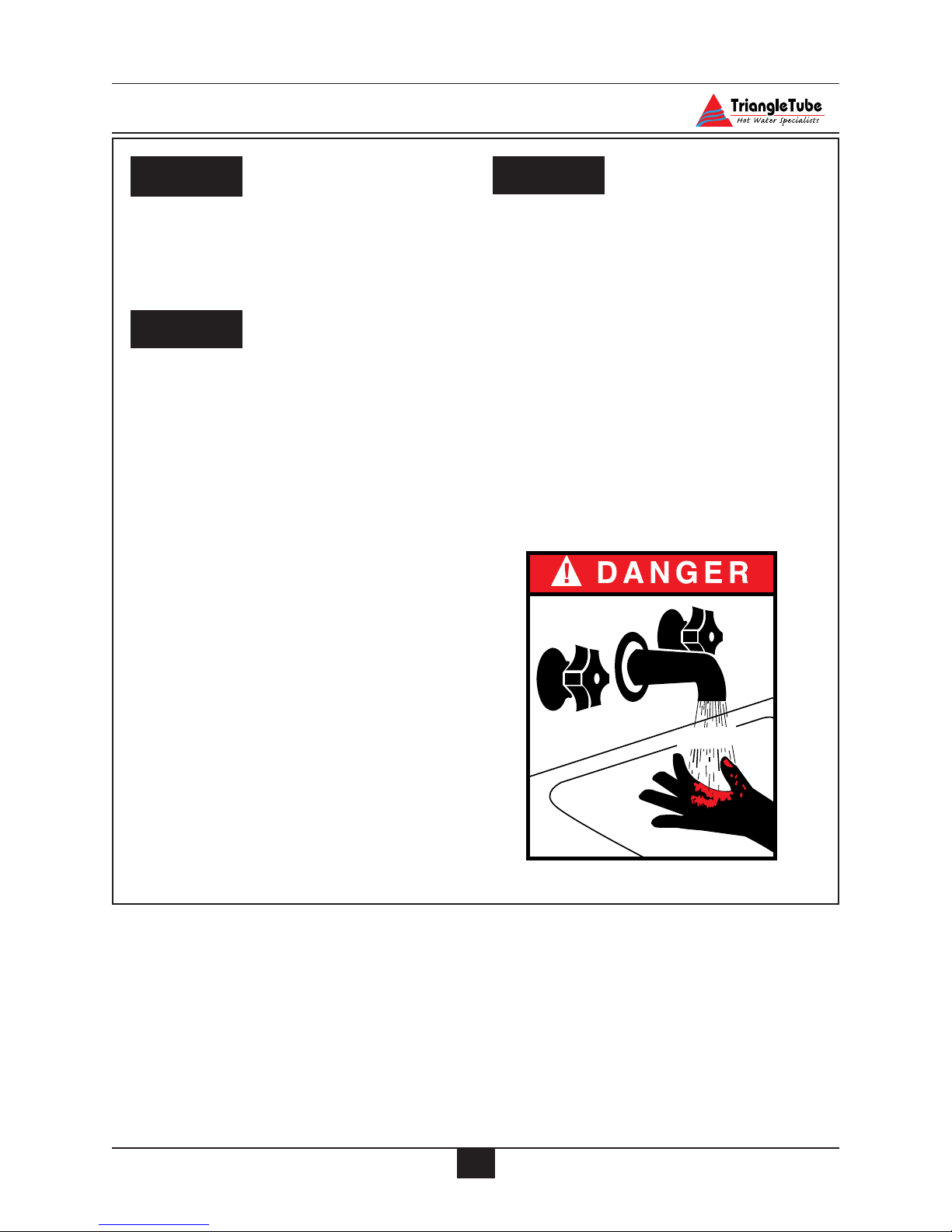
Water temperature over 125ºF can cause
severe burns instantly or death from
scalds.
• Children, disabled and elderly are at
highest risk of being scalded.
- Never leave them unattended in or
near shower, bathtub or sink.
- Never allow small children to use a
hot water faucet or draw their own
bath.
• If any one using hot water in the building
fits this description or codes require specific water temperatures at hot water
faucet, we recommend:
a) ensure the factory installed thermosta-
tic mixing valve is working properly.
b)to set the thermostatic mixing valve
for the lowest temperature which satisfies your hot water need.
.
Protection must be taken against excessive
temperature and pressure!
TO PROTECT AGAINST EXCESSIVE
TEMPERATURE AND PRESSURE
• Check if the Temperature and
Pressure (T&P) relief valve is in the
location provided. (Domestic Water)
• Check if the 30 psi relief valve supplied is in the location provided.
(Primary water)
•To avoid injury, install the relief
devices to comply with local code
requirements.
CAUTION
DANGER
WARNING
HOT
BURN
Page 10
3
Product & Safety Information
Do not use this appliance if any part
has been under water. Immediately call
a qualified service technician to inspect
the appliance and to replace any part of
the control system which has been
under water.
WHAT TO DO IF YOU SMELL GAS
- Do not try to light any appliance
- Do not touch any electrical switch; do
not use any phone in your building.
- Immediately call your gas supplier
from a neighbor’s phone. Follow the
gas supplier’s instructions.
- If you cannot reach your gas supplier, call the fire department.
Installation and service must be performed by a qualified installer, service
agency or the gas supplier.
Should overheating occur or the gas
supply fails to shut off, turn OFF the
manual gas control valve external to
the appliance.
To prevent damage to inner tank,
installer must:
• Fill inner tank prior to outer tank
during start-up.
• Relieve primary system pressure
below 15 psig prior to draining
inner tank.
CAUTION
WARNING
DANGER
DANGER
Qualified Installer:
Prior to installing this product read all
instructions included in this manual.
Perform all installation steps required in this
manual in the proper order given. Failure to
adhere to the guidelines within this manual
can result in severe personal injury, death or
substantial property damage.
Homeowner:
-This product should be maintained / serviced and inspected annually by a qualified Service Technician.
- This manual is intended for use by a
qualified Installer/Service Technician.
Please reference the unit’s model number and the serial number from the rating label when inquiring about service or
troubleshooting.
Triangle Tube accepts no liability for any
damage resulting from incorrect installation or from the use of components or
fittings not specified by Triangle Tube.
NOTICE
NOTICEWARNING
Page 11

OPERATING RESTRICTIONS
• Maximum working pressure for inner
(domestic water) tank is 150 psig.
• Maximum working pressure for outer
(primary water) tank is 45 psig.
• Inner tank has factory installed
Temperature & Pressure Relief Valve
with an AGA rating of 100,000 Btu/hr
for PG-25 and 200,000 Btu/hr for PG30/35/40/45.
• Outer tank has a factory installed 30
psig relief valve rated at 535,000 Btu/hr
• Electrical rating:120 V, 60 Hz, less
than 12 amperes
• pH & chloride limits for the PERFORMANCE are:
- Chloride, less than 80 mg/l.
- pH, 6.0 - 8.0.
Any water conditioning system must be
installed and maintained in accordance
with manufacturer’s specifications.
• 180º F Maximum operating temperature - primary side.
• 120º F Maximum outlet/mixed temperature - domestic side.
CODE RESTRICTIONS
Single wall heat exchanger in the PERFORMANCE complies with National Standard
Plumbing Code, provided that:
- Outer tank water (including additives)
is practically non-toxic, having toxicity
rating or Class of 1, as listed in Clinical
Toxicology of Commercial Products,
- Outer tank pressure is limited to maximum 30 psig by approved relief valve.
Single wall heat exchangers are permitted under
the Uniform Plumbing code - Paragraph L3.2. if
they satisfy all of the following requirements.
1. The heat transfer medium is potable
water or contains only substances which
are recognized as safe by the U.S. Food
and Drug Administration.
2. The pressure of the heat transfer medium
is maintained less than the normal minimum operating pressure of the potable
water system
3. The equipment is permanently labeled
to indicate that only additives recognized as safe by the FDA shall be used in
the heat transfer medium.
Or, per Uniform Plumbing Code paragraph L3.3
as follows:
Other heat exchanger designs may be permitted
where approved by the Administrative Authority.
NOTICE
4
Product & Safety Information
Page 12

Pre-Installation Items
5
SECTION I - Pre-Installation Items
Code Compliance
This product must be installed in accordance to the following:
• All applicable local, state, national and
provincial codes, ordinances, regulations and laws.
• The National Fuel Gas Code NFPA54/
ANSI Z332.1 - Latest edition.
• National Electric Code ANSI/NFPA 70.
• For installations in Canada -“Installation
Code for Gas Burning Equipment”
CGA/B149.
Determining Product Location
Before locating the PERFORMANCE check
for convenient locations to:
- Domestic water supply piping
- Heating system piping
-Venting
- Gas supply piping
- Electrical service
Ensure the area chosen for the installation of
the PERFORMANCE is free of any combustible materials, gasoline and other flammable liquids.
Failure to remove or maintain the area
free of combustible materials, gasoline
and other flammable liquids or vapors
can result in severe personal injury,
death or substantial property damage.
Ensure the PERFORMANCE and its controls
are protected from dripping or spraying water
during normal operation or service.
The PERFORMANCE should be installed
in a location so that any water leaking from
the tank or piping connections or relief
valves will not cause damage to the area
surrounding the unit or any lower floors in
the structure.
- When such a location is unavoidable a
suitable drain pan with adequate
drainage should be placed under the
unit. The drain pan must not restrict the
flow of combustion air to the unit.
Boiler Replacement
If the PERFORMANCE is replacing an existing boiler / hot water heater system, the following items should be checked and corrected
prior to installation:
• Primary and domestic piping leaks and
corrosion.
• Improper location and sizing of the
expansion tank on the primary heating
loop.
• Improper sizing of the thermal expansion tank (if used) on the domestic supply line.
•Vent condition and sizing.
Recommended Clearances
The PERFORMANCE is approved for zero
clearance to combustibles, excluding the vent
hood and vent piping.
Vent hood and vent piping - 2 inches from
combustible materials unless otherwise stated
by the vent pipe manufacturer.
Primary and domestic hot water piping - 1 inch
from combustible material.
WARNING
Page 13

To provide serviceability to the unit it is
recommended that the following clearances be maintained:
Top and vent hood area - 36 inches.
Front and burner area - 24 inches.
Rear and primary piping areas - 12
inches.
When installing the PERFORMANCE
in a confined space, sufficient air must
be provided for proper combustion and
venting and to allow under normal operating condition proper air flow around
the product to maintain ambient temperatures within safe limits to comply with
the National Fuel Gas Code NFPA 54 latest edition.
Flooring and Foundation
The PERFORMANCE is approved for installation on combustible floors, but never on carpeting.
Do not install the PERFORMANCE on
carpeting even with a metal or wood
foundation base. Fire can result causing
severe personal injury, death or substantial property damage.
Installer should provide a solid brick or concrete foundation pad, at least 2 inches above
the floor level if:
- There is a potential for the floor to
become flooded. The height of the
foundation should be such to sufficiently elevate the unit.
- The floor is dirt, sand, gravel or other
loose material.
- The flooring is severely uneven or
sloped.
The minimum foundation size required is 24
inches x 23 inches.
Residential Garage Installations
When installing the PERFORMANCE in a residential garage the following special precautions
per NFPA 54/ANSI Z223.1 must be taken:
- Mount the unit with a minimum 18
inches above the floor level of the
garage. Ensure the burner and ignition
devices / controls are no less than 18
inches above the floor level.
- Locate or protect the unit in a matter
so it cannot be damaged by a moving
vehicle.
WARNING
WARNING
BEST PRACTICES
6
Pre-Installation Items
Page 14

Combustion Air and Venting
7
SECTION II - Combustion Air and
Venting
Combustion Air Contamination
If the PERFORMANCE combustion air
inlet is located in any area likely to cause
or contain contamination, or if products,
which would contaminate the air cannot
be removed, the combustion air must be
repiped and terminated to an outside
location. Contaminated combustion air
will damage the unit and its burner system, resulting in possible severe personal
injury, death or substantial property
damage.
Do not operate a PERFORMANCE if its
combustion air inlet is taken inside in a
laundry room or pool facility. These
areas will always contain hazardous contaminants.
Pool chemicals, laundry products, common household cleaners and hobby
products often contain fluorine or chlorine compounds. When these chemicals
pass through the burner and vent system, they can form strong acids. These
acids can create corrosion of the outer
tank, burner components and vent system, causing serious damage and presenting a possible threat of flue gas
spillage or water leakage into the surrounding area.
Please read the information listed below.
If contaminating chemicals are located
near the location of the combustion air
inlet, the installer should pipe the combustion air inlet to an outside area per
SECTION VI of this installation manual.
Potential contaminating products
- Spray cans containing chloro/fluorocarbons
- Permanent Wave Solutions
- Chlorinated wax
- Chlorine - based swimming pool chemicals / cleaners
- Calcium Chloride used for thawing ice
- Sodium Chloride used for water softening
- Refrigerant leaks
- Paint or varnish removers
- Hydrochloric acid / muriatic acid
- Cements and glues
- Antistatic fabric softeners used in
clothes dryers
- Chlorine-type bleaches, detergents, and
cleaning solvents found in household
laundry rooms
- Adhesives used to fasten building products and other similar products
Areas likely to contain these products
- Dry cleaning / laundry areas and establishments
- Beauty salons
- Metal fabrication shops
- Swimming pools and health spas
- Refrigeration Repair shops
- Photo processing plants
- Auto body shops
- Plastic manufacturing plants
- Furniture refinishing areas and establishments
- New building construction
- Remodeling areas
- Garages with workshops
WARNING
WARNING
Page 15
Combustion Air Requirements
The PERFORMANCE can use inside air if no
contaminants are present in the area of installation when venting as a Category I or Category
III appliance. If contaminants are likely to be
present in the area of installation, outside air
must be piped directly to the unit as referenced
in Section VI Venting and Combustion Air
Installation.
In order to avoid the potential of indoor
contaminates when venting as either a
Category I or Category III appliance it is
recommended to pipe uncontaminated
combustion air directly from the outdoors to the unit as referenced in Section
VI Venting and Combustion Air
Installation.
Outside Combustion Air
Combustion air can be ducted directly from the
outside to the air inlet fitting of the PERFORMANCE (Category I or Category III vent
applications) using the following materials:
- PVC
- Galvanized metal vent
- Flexible metal vent
All seams and joints must be sealed with
sealant or mechanical fasteners. Do not use
tape as it is not considered a sealing material.
Air Openings
Air openings to the PERFORMANCE are
always required even if the combustion air is
obtained indoors or outdoors. These air openings provide ventilation to prevent overheating
of the PERFORMANCE and its control as well
as providing combustion air.
The air openings must be sized to handle
the requirements of all appliances and air
movers (exhaust fans, etc.) contained in
the same space using the same air supply.
Methods of Accessing Combustion Air Into A
Space
Indoor Combustion Air
The methods listed in this section for
accessing Indoor Combustion Air
assume that the infiltration rate is adequate and not less than .40 ACH. For
infiltration rates less than .40 ACH, reference the NFPA 54 National Fuel Gas
Code for additional guidance.
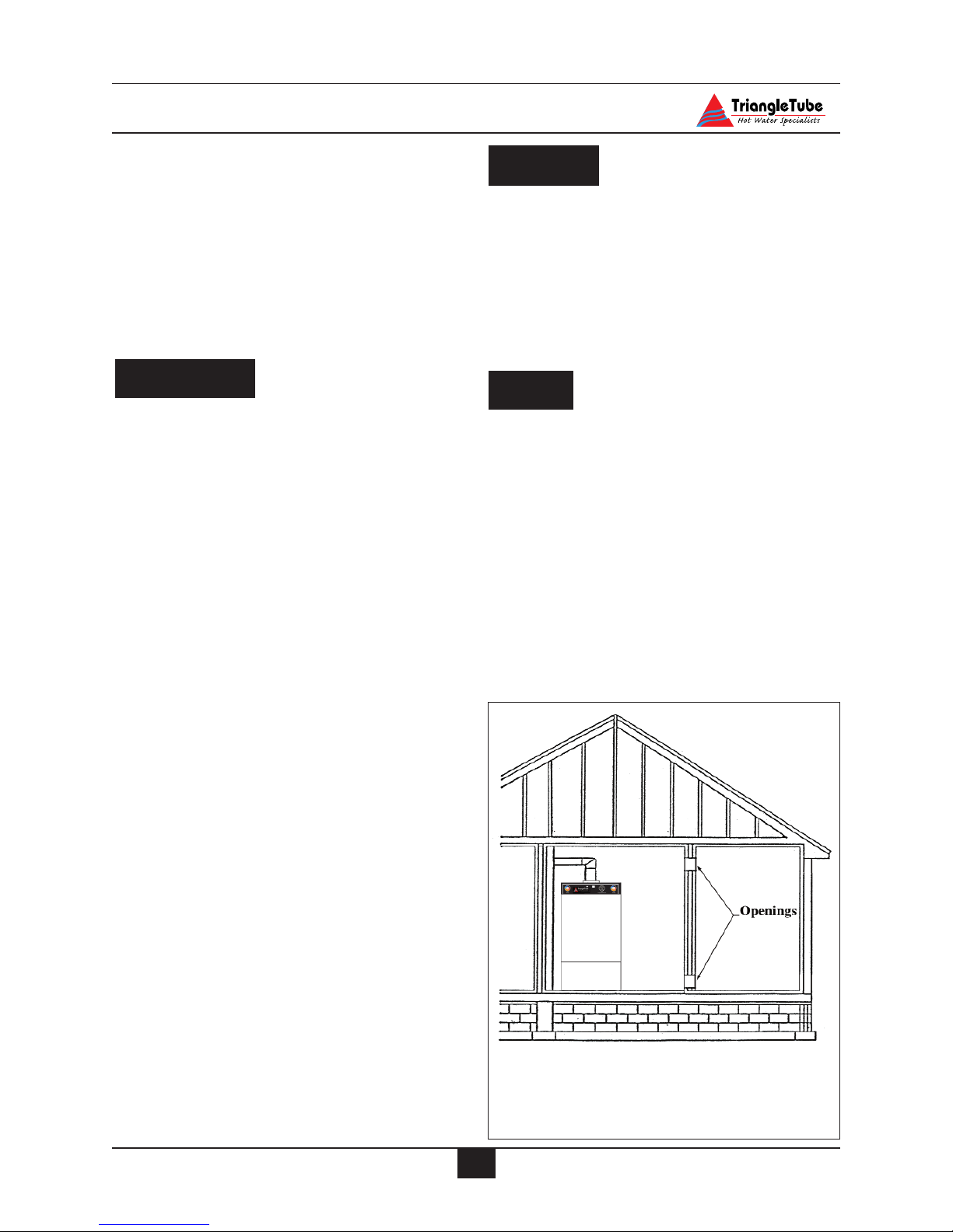
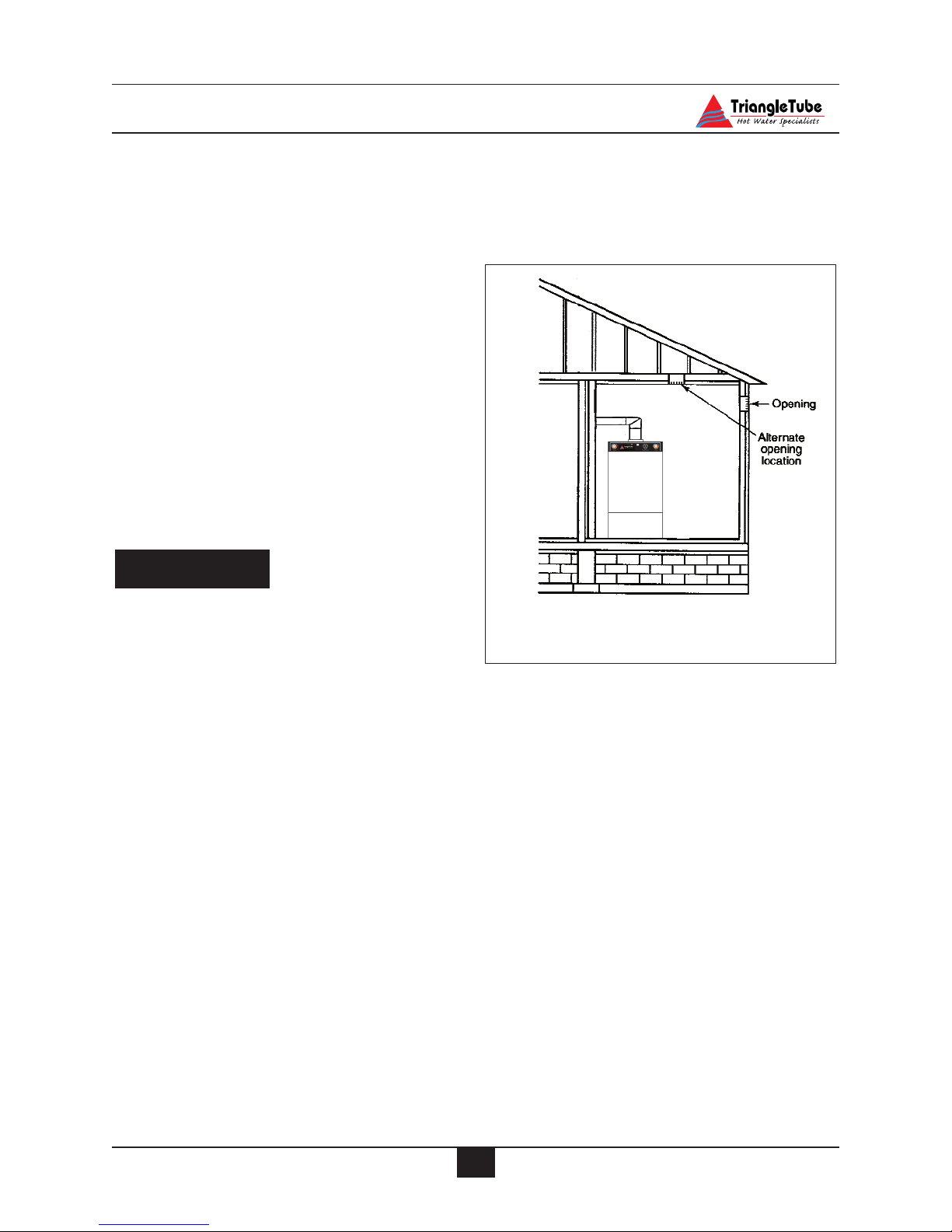
Opening Size and Location
Openings used to connect indoor spaces shall
be sized and located in accordance with the
following see Fig. 1:
NOTICE
NOTICE
BEST PRACTICE
8
Combustion Air and Venting
Equipment Located in Confined
Spaces; All Air from inside the
building.
Fig. 1:
Page 16
9
Combustion Air and Venting
- Combining spaces on the same story.
Each opening shall have a minimum
free area of 1 sq. in./1000 Btu/hr of the
total input rating of all gas utilization
equipment in the space, but not less than
100 sq. inches. One opening shall commence within 12 inches of the top, and
one opening shall commence within 12
inches of the bottom of the enclosure.
- Combining spaces in different stories.
The volumes of spaces in different stories shall be considered as communicating spaces where such spaces are connected by one or more openings in
doors or floors having a total minimum
free area of 2 sq. in./1000 Btu/hr of
total input rating of all gas utilization
equipment.
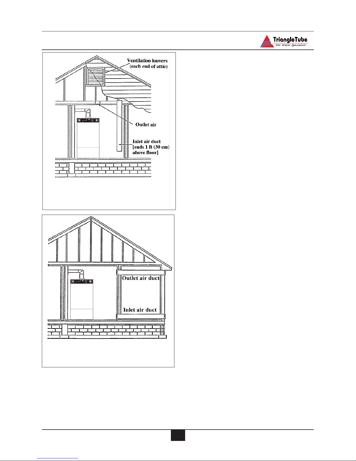
Outdoor Combustion Air
Isolating the combustion appliance room
from the rest of the building and bringing in uncontaminated outside air for
combustion and ventilation is always
preferred.
Opening Size and Location
Openings used to supply combustion and ventilation air shall be sized and located in accordance with the following:
One Permanent Opening Method. See Fig. 2
One permanent opening, commencing within 12
in. of the top of the enclosure, shall be provided.
The equipment shall have clearances of at least 1
inch from the sides and back and 6 in. from the
front of the appliance. The opening shall directly communicate with the outdoors or shall communicate through a vertical or horizontal duct to
the outdoors or spaces that freely communicate
with the outdoors and shall have a minimum free
area of the following:
- 1sq. in./3000 Btu/hr of the total input
rating of all equipment located in the
enclosures, and
-Not less than the sum of the areas of all
vent connectors in the space.
Two Permanent Openings Method.
Two permanent openings, one commencing
within 12 in. of the top and one commencing
within 12 in. of the bottom of the enclosure,
shall be provided. The openings shall communicate directly, or by ducts, with the outdoors
or spaces that freely communicate with the outdoors, as follows:
- Where directly communicating with the
outdoors or where communication to the
outdoors is through vertical ducts, each
opening shall have a minimum free area
of 1 sq. in./4000 Btu/hr of total input rating of all equipment in the enclosure.
See Fig.3.
- Where communicating with the outdoors is through horizontal ducts, each
opening shall have a minimum free
area of not less than 1 sq.in./2000
Btu/hr of total input rating of all equipment in the enclosure. See Fig. 4.
BEST PRACTICE
Equipment Located in Confined
Spaces; One Permanent Air Inlet
Fig. 2:
Page 17
Combination of Indoor and Outdoor
Combustion Air
Indoor Openings: Where used, openings connecting the interior spaces shall comply with
the Indoor Combustion Air section on page 8.
Outdoor Opening(s) Location. Outdoor opening(s) shall be located in accordance with the
Outdoor Combustion Air section.
Outdoor Opening(s) Size. Outdoor opening(s)
shall be calculated in accordance with the following:
- The ratio of the interior spaces shall be
the available volume of all communicating spaces divided by the required
volume.
- The outdoor size reduction factor shall
be 1 minus the ratio of interior spaces.
- The minimum size of outdoor opening(s) calculated in accordance with the
above outdoor air section multiplied by
the reduction factor. The minimum
dimension of air openings shall not be
less than 3 in.
Vent System
The PERFORMANCE is designed to vent
as a Category I appliance using standard
gas vent or, as a Category III appliance,
which requires a special vent system.
Category III Venting is described as a vent
system that has a positive static pressure
and a flue temperature that avoids excessive condensate within the vent.
10
Combustion Air and Venting
Equipment Located in Confined
Spaces; All Air from Outdoors
Through Ventilated Attic
Fig. 3:
Equipment Located in Confined
Spaces; All Air from Outdoors
Fig. 4:
Page 18

11
Combustion Air and Venting
Do not install the PERFORMANCE into
a common vent with other gas appliances
when venting as a Category III appliance.
This may cause flue gas spillage or appliance malfunction, resulting in possible
severe personal injury, death or substantial property damage.
Removal of an Existing Boiler from a
Common Vent System
For installations in which the PERFORMANCE is installed as a category I
Appliance and is replacing an existing
boiler / hot water heater system, connected to a common vent system with other
appliances, the following steps shall be
conducted with each remaining appliance
connected to the common venting system:
1. Any unused openings in the common
venting system must be sealed.
2. A visual inspection of the venting system must be conducted for proper sizing and horizontal pitch. The inspection should ensure no blockage or
restriction is within the vent system,
and there is no leakage, corrosion or
other items, which could cause an
unsafe condition.
3. To adequately test the venting system,
close all exterior doors and windows
and all doors between the area containing the remaining appliances connected
to the common vent system and other
areas of the building. Turn on any
clothes dryers and any other gas appliance not connected to the common vent
system. Turn on all exhaust fans, i.e.
range hoods and bathroom exhaust
fans, preferably at maximum speed.
Close any fireplace dampers.
4. Place in operation the first appliance
being inspected that is connected to the
common vent system. The remaining
appliances should not be in operation.
Follow the appliance’s lighting instructions and adjust the thermostat to allow
the appliance to operate continuously.
5. Test for spillage at the draft hood relief
opening after 5 minutes of main burner
operation. Spillage can be detected
using the flame of a match or candle or
with smoke from a cigarette.
6. Once it has been determined that each
remaining appliance connected to the
common vent system is properly vented, return doors, windows, exhaust
fans, fireplace dampers and any operating gas appliance to their previous condition.
Should any improper operation of the common
venting system be detected in the outline test,
the condition should be corrected so the vent
system conforms with the National Fuel Gas
Code, NFPA 54/ ANSI Z223.1 - latest edition.
Canadian installations must conform with
B149.1 or 149.2 Installation Code.
BEST PRACTICES
DANGER
Page 19

Unit Preparation
12
SECTION III - Unit Preparation
Handling Instructions
The PERFORMANCE is generally easier to
handle and maneuver once removed from the
shipping carton and pallet.
To remove the shipping carton and pallet:
a. Remove the shipping straps and open
the top of the carton to remove the
wood shipment insert.
b. Lift the carton over the unit to remove.
If ceiling height is limited, the carton
maybe cut open using care not to damage the exterior jacket of the unit.
c. Remove the front burner hood to pre-
vent damage prior to lifting the unit
from the shipping pallet.
When lifting or moving the unit do not
use the burner or its components as a
means of a handle. Hand-truck the unit
from the rear only.
d. Discard all packing materials.
Hydrostatic Pressure Test
Prior to permanently connecting water,
gas supply or electrical supply, perform
a pressure hydrostatic test of the outer
tank to ensure all piping connections
were not damaged during shipment.
Hydrostatic Test Preparation
1. Mount the circulator on the supply pipe as
shown in Figure 11 page 23.
2. Temporarily plug the primary return connections as shown in Figure 11 using a 1”
NPT pipe plug. Use pipe dope sparingly to
allow removal of the plugs upon completion of the test.
3. On the outlet flange of the circulator pipe
install a 1” NPT nipple and shut-off valve.
Use pipe dope sparingly to allow removal
of the fittings upon completion of the test.
To avoid getting water onto the unit
and/or surrounding area, additional piping from the shut-off to a catch bucket or
drain may be required.
4. Connect a hose to the primary circuit drain
valve located per Figure 45 page 70, Item 2
and connect the other end to a fresh water
supply. Ensure the hose can be used as a
drain hose upon completion of the test.
Hydrostatic Test Procedures
1. Open the shut-off valve installed on the
outlet flange of the circulator.
2. Open the fresh water supply valve and then
open slowly the primary circuit drain valve
to fill the outer tank with water.
3. When the water within the outer tank
reaches the shut-off on the primary supply,
close the primary circuit drain valve.
4. Close the shut-off valve, on the top of the
circulator.
5. Slowly reopen the primary circuit drain
valve until the test pressure on the temperature / pressure gauge reaches 10 psig
maximum. Close the primary circuit drain
valve and fresh water supply valve.
To prevent damage to the inner tank the
test pressure must not exceed 10 psig.
6. Allow the test pressure to remain for 10
minutes.
CAUTION
NOTICE
BEST PRACTICES
WARNING
Page 20

Unit Preparation
Do not leave the unit unattended while
pressurized. A cold water fill could
expand and cause excessive pressure,
resulting in severe personal injury, death
or substantial property damage.
7. Ensure constant gauge pressure has been
maintained throughout the 10 minute test.
Check for leaks at all fitting joints. Repair
if found.
Leaks must be repaired immediately
when detected. Failure to repair leaks
can damage the unit, resulting in substantial property damage.
8. Check continuity using a voltmeter across
the terminals of the LWCO device. The
contacts on the LWCO should be closed.
See item 6 Figure 40 page 66 for location
of the LWCO.
Completion of Hydrostatic Test and Draining
1. Disconnect the fill hose from the fresh
water source and direct the hose to a suitable place of drainage.
2. Open the primary drain valve and completely drain the unit. To aid in draining open the
shut-off valve on the primary supply.
3. Remove the hose from the primary drain
valve when draining is complete.
4. Remove the plugs, nipple, shut-off valve
and any other piping unless they will
remain for use in the system piping.
WARNING
WARNING
13
Page 21
Domestic Piping
SECTION IV - Domestic Piping
General Piping Requirements
• All plumbing must meet or exceed all
local, state and national plumbing codes.
• Use pipe dope or tape suitable for
potable water.
• Use isolation valves to isolate system
components.
• Install unions for easy removal of the
PERFORMANCE from the system
piping.
Domestic Supply Pressure
For applications in which the domestic supply pressure exceeds 70 psig it is recommended to install a pressure reducing valve
on the cold water supply.
Maintaining the cold water supply at or
below 70 psig will prevent normal thermal
expansion from repeatedly forcing the T&P
relief valve open.
Thermal Expansion
If the cold water supply to the domestic
inner tank contains a backflow preventer,
check valve and / or a pressure reducing
valve, the installer must install a domestic
thermal expansion tank on the cold water
supply. (See Fig. 6 page 17)
Installing a thermal expansion tank will
prevent normal thermal expansion from
repeatedly forcing the T&P relief valve
open.
When installing a thermal expansion tank
ensure the charge pressure of the tank is
equal to the cold water supply pressure at
the point of installation. Consult the thermal expansion tank manufacturer’s instructions for further information on installation
and sizing.
The Temperature / Pressure relief valve
is not intended for constant duty, such as
relief of pressure due to normal thermal
expansion.
Water Hammer
Water hammer is the effect of sudden pressure changes occurring in the domestic piping. These pressure changes are typically
the result of “fast acting” positive shut-off
valves closing. These types of valves can
be typically found on dishwashers and
clothes washers.
The effects of water hammering can cause
damage to system components and tank
welds on the unit.
Installation of hammer arresters is recommended at these types of appliances, which
incorporate “fast-acting” positive shut-off
valves. Consult the manufacturer of water
hammer arresters for recommendation on
sizing and installation requirements.
Temperature / Pressure Relief Valve
The PERFORMANCE has a factory
installed Temperature / Pressure Relief
valve. Ensure the rating of the T&P relief
valve is correctly sized as follows per
AGA:
CAUTION
14
Model AGA Rating
PG-25 100,000 Btu/hr
PG-30 200,000 Btu/hr
PG-35 200,000 Btu/hr
PG-40 200,000 Btu/hr
PG-45 200,000 Btu/hr
Page 22

Domestic Piping
The installer must install discharge piping
onto the T&P relief valve. The discharge
piping must be:
• Made of material serviceable for temperatures of 250ºF or greater.
• Directed so that any hot water discharge flows away from all persons.
• Directed to a suitable place of drainage.
• Installed as to allow complete draining
of the T&P relief valve and the discharge piping.
•Terminated with a plain end, not with
threads.
Failure to properly direct the discharge
piping of the T&P relief valve may result
in flooding of the area adjacent to the
unit and or lower floors in the structure
causing substantial property damage.
The installer must not install the T&P
relief valve discharge piping in a manner
that is:
• Excessively long: Using more than 2
elbows and/or 15 feet of discharge piping can reduce the discharge capacity.
•Terminated directly into a drain: The
discharge piping must terminate within
6 inches of the drain. Check with local
plumbing codes for termination guidelines.
• The discharge piping is plugged, reduced
in size or restricted in any manner.
• The discharge piping is subject to freezing.
DO NOT install any valves between the
T&P relief valve and the discharge piping. DO NOT plug the T&P relief valve
or the discharge piping. Improper placement and piping of the T&P relief valve
can cause severe personal injury, death
or substantial property damage.
Thermostatic Mixing Valve
The PERFORMANCE contains a factory
installed thermostatic mixing valve with builtin check valve.
The operating range of the thermostatic mixing
is 90ºF to 120ºF.
For applications with a domestic recirculation
loop, the recirculation pump should be controlled by an aquastat. The maximum recommended setting of the aquastat is 10ºF lower
than the thermostatic mixing valve setting.
For proper operation of the thermostatic
mixing valve and to prevent potential
scalding hazards, the recirculation loop
should be controlled by an aquastat. DO
NOT use continuous recirculation.
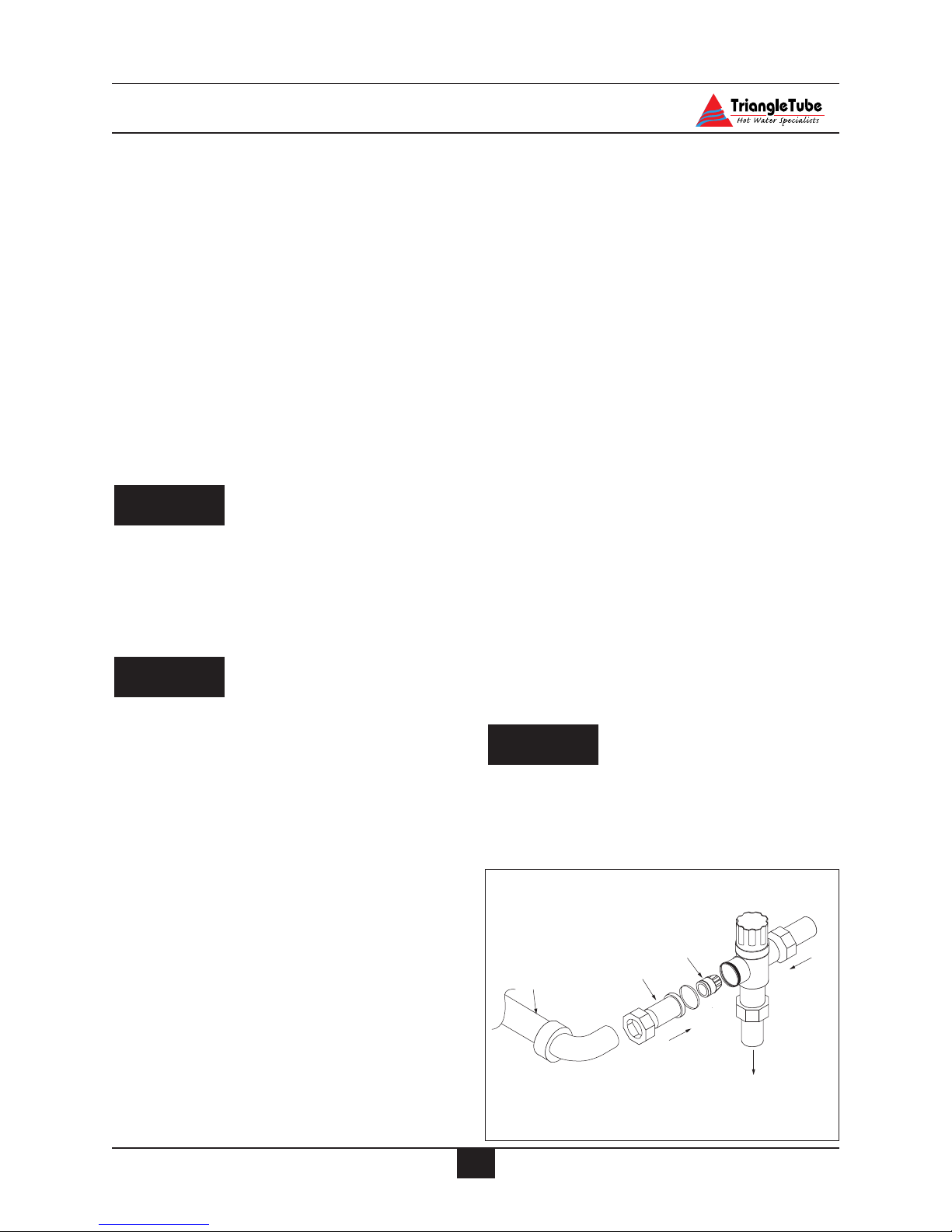
U-Tube Assembly
The PERFORMANCE is supplied with a
U-Tube Assembly that directs cold water to
the thermostatic mixing valve.
To install the U-Tube Assembly the
installer must:
1. Disconnect the cold inlet adapter/union
from the thermostatic mixing valve.
2. Use needle-nose pliers to remove the
plastic check valve assembly from the
adapter.
DANGER
WARNING
CAUTION
15
Page 23
16
Domestic Piping
3. Solder the U-Tube Assembly onto the
adapter. (See Fig. 5)
4. Once the adapter has sufficiently
cooled, re-insert the check valve assembly making sure of orientation and
reconnect onto the mixing valve.
If the installation of the PERFORMANCE
requires domestic hot water for a commercial dishwasher, the installer may insert a
tee connection between the unit and the
mixing valve to provide 140ºF domestic
hot water. The installer must reference
local plumbing codes to ensure if this type
of application is permissible.
The thermostatic mixing valve MUST be
installed and utilized on the PERFORMANCE. Removal of the thermostatic
mixing valve will result in severe personal injury or death.
The manual valve on the U-Tube assembly must remain in the full open position
for proper operation of the thermostatic
mixing valve.
Domestic Drain Valve
- The installer must install a drain valve
and drain leg as shown in Fig. 6 page 17
or Fig. 7 page 18.
- The drain valve should be positioned
close to the floor to aid in the siphon
action required to drain the inner tank.
Multiple Units Installation
For applications using multiple units the
domestic piping should be piped using a balanced manifold arrangement.
The installer should remove the thermostatic
mixing valve from the units and install a single
thermostatic mixing valve at the outlet of the
hot water manifold. The thermostatic mixing
valve should be sized according to the required
flow rate and pressure drop. Refer to the thermostat mixing valve manufacturer specification and installation instructions for more
details.
Reference Fig. 8, page 18 for piping diagram.
Storage Tank Application
For applications requiring large volumes of
domestic hot water in a relative short period,
the installer may include a storage type tank
(see Fig. 9 page 19) in the domestic piping.
The installer must:
1. Relocate the thermostatic mixing valve
from the PERFORMANCE to the outlet of the storage tank.
2. Provide recirculation from the storage
tank back to the PERFORMANCE
using a bronze type circulator.
Maximum recommended flow rate is 5
to 10 gpm.
This can be accomplished through the
drain connection if a 3rd tapping is
unavailable and the circulator should be
controlled by an aquastat.
NOTE
CAUTION
DANGER
Fig. 5: Mixing Valve Assembly
U-Tube Assembly
Adapter
Check Valve
Cold
Mixed
ot
H
Page 24
17
Domestic Piping
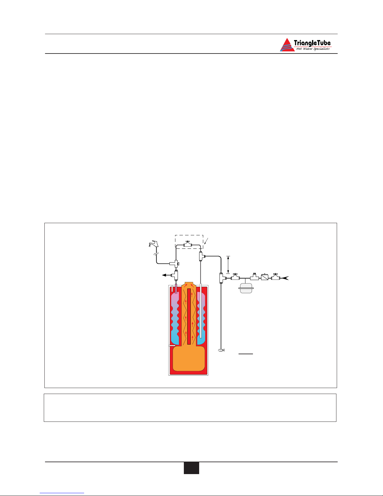
Fig. 6: PERFORMANCE Without
Recirculation
Note: All shut off valves shown in
this figure must be shut when siphon
draining the PERFORMANCE
Domestic Piping Diagrams
1. Mixing valve with check valve
3. Shut off valve
4. Backflow preventer or pressure reducing valve*
6. Thermal expansion tank
8. Domestic drain valve
9. Vacuum breaker*
* Optional devices may be required by local Codes
TR/SMART Series Application
For applications requiring large volumes of
domestic hot water over an extended period,
the installer may include a Triangle Tube
TR/SMART Indirect Water Heater in conjunction with the PERFORMANCE. (See Fig. 10
page 19)
The domestic system recirculation, if used, is
directed to the TR/SMART Series Tank. The
circulator should be controlled by an aquastat.
The primary piping to the TR/SMART Series
tank must comply with the piping methods
details in SECTION V - Primary Piping or with
other recognized piping methods.
Additional information regarding domestic and
primary piping can be found in the TR/SMART
Installation Manual.
U-Tube assembly
3
Re-attach valve handle
when draining inner tank
To dishwasher if
permitted by codes
1
8
12" Heat trap
3
9
4
6
3
Cold water
inlet
Page 25

18
Domestic Piping
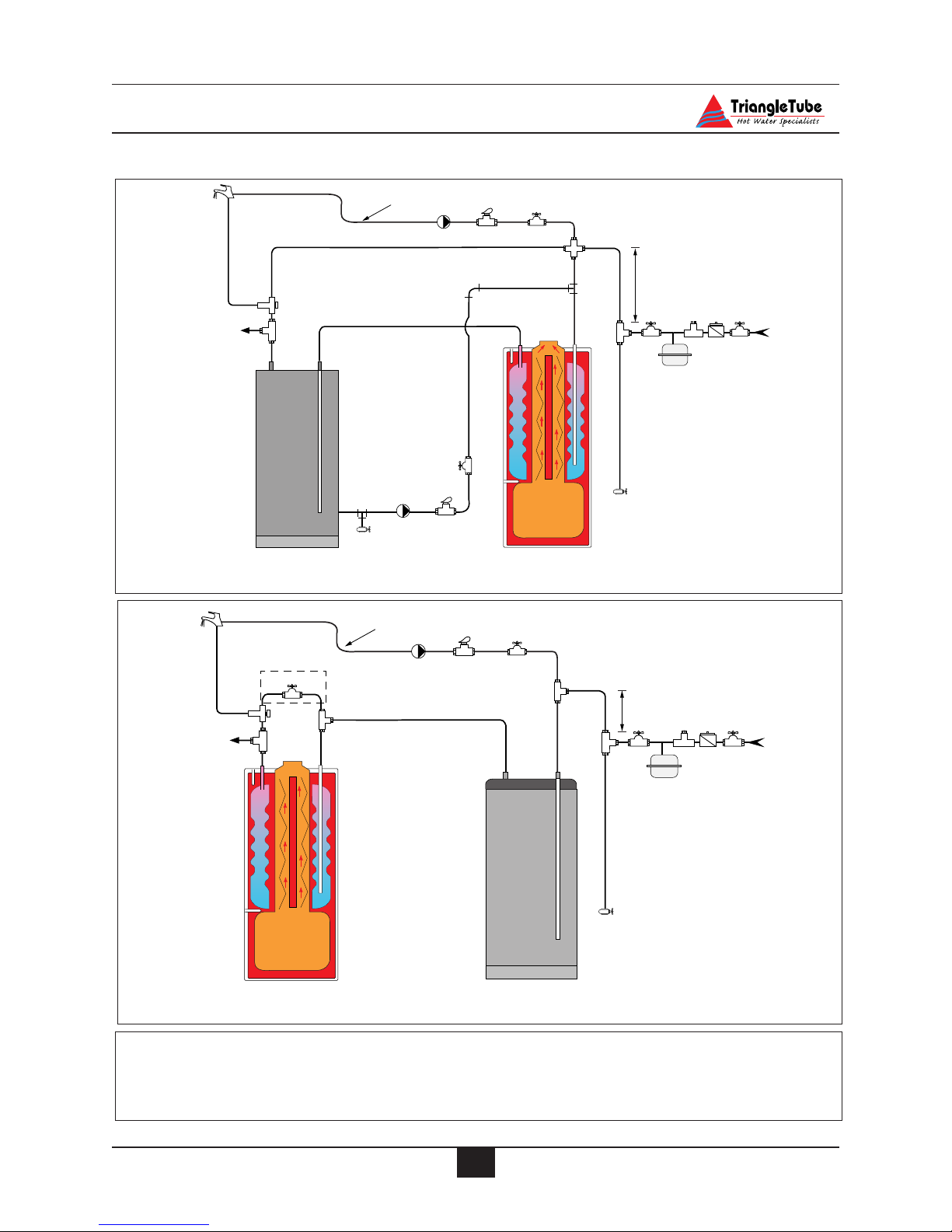
Fig. 7: PERFORMANCE With
Recirculation
1. Mixing valve with check valve
2. Flow check valve
3. Shut off valve
4. Backflow preventer or pressure reducing valve*
6. Thermal expansion tank
7. Circulator (controlled by aquastat)
8. Domestic drain valve
9. Vacuum breaker*
Note: All shut off valves
shown in this figure must be
closed when siphon draining
the PERFORMANCE
* Optional devices may be required by local Codes
Fig. 8: Multiple Units Installation With Recirculation
Optional recirculation
7
To dishwasher if
permitted by codes
U-Tube
3
2
1
assembly
3
*
12" Heat trap
3
8
9
4
6
3
Cold water
inlet
7
1
2
3
12" Heat trap
3
8
4
9
6
inlet
Cold water
3
Page 26
19
Domestic Piping
Fig. 10: PERFORMANCE with TR/SMART Indirect Water Heater
Fig. 9 : PERFORMANCE with Storage Tank
1. Mixing valve with check valve
2. Flow check valve
3. Shut off valve
4. Backflow preventer or pressure reducing valve*
6. Thermal expansion tank
7. Circulator (controlled by aquastat)
8. Domestic drain valve
9. Vacuum breaker*
Domestic Piping Diagram
* Optional devices may be required by local Codes
Optional recirculation line
7
1
To dishwasher if
permitted by codes
2
7
8
Optional recirculation line
3
7
3
2
12" Heat trap
Cold water
3
6
3
8
3
2
3
9
4
inlet
1
To dishwasher if
permitted by codes
12" Heat trap
3
8
4
6
inlet
Cold water
3
9
Page 27

20
Primary Piping
SECTION V - Primary Piping
General Piping Requirements
Low Water Cutoff Device
- The PERFORMANCE is equipped with a
factory installed pressure switch style
Low Water Cut Off device.
- The minimum operating system pressure
allowable with this device is 10 psig.
- Check local codes which require a low
water cutoff device for compliance of
this device.
Backflow Preventer
- Use a backflow preventer valve in the
make-up water supply to the unit as
required by local codes.
Primary System Piping Applications
All piping applications shown in this installation manual utilize a primary/ secondary
piping arrangement. This method is recommended as a means to provide priority
to the production of domestic hot water.
For other piping arrangements, consult the
Engineering Department at Triangle Tube
or consult other approved/recognized
design arrangements.
On piping applications utilizing a single
zone or other recognized piping design
arrangements, it is recommended the
installer uses flow/check valves with
weighted seats at or near the appliance to
prevent gravity circulation.
To prevent potential outer tank failure,
the primary system piping must be a
“closed” loop sytem to avoid any oxygen
contamination of the boiler water.
Expansion Tank and Makeup Water
Ensure the expansion tank is properly sized
for the outer tank volume (20 gallons) and
the system volume and temperature.
Undersized expansion tanks will cause system water to be lost through the pressure
relief valve and cause additional makeup
water to be added to the system. Eventual
primary tank failure can result due to this
excessive makeup water addition.
The expansion tank must be located as
shown in Figure 11, 11A or 11B page 23 or
as per recognized design methods. Refer to
the expansion tank manufacturer instructions for additional installation details.
Connect the expansion tank to an air separator only if the air separator is located on
the suction side (inlet) of the system circulator. Always locate and install the system
fill connection at the same location as the
expansion tank connection to the system.
Diaphragm (Bladder) Expansion Tank
Always install an automatic air vent on the
top of the air separator to remove residual
air from the system.
Closed-Type (Standard) Expansion Tank
It is recommended to pitch any horizontal
piping toward the expansion tank 1 inch per
5 feet of piping. Use 3/4” piping for the
expansion tank to allow air within the system to rise.
CAUTION
NOTICE
BEST PRACTICE
BEST PRACTICE
Page 28

21
Primary Piping
For proper operation of the expansion tank
and system, remove the factory installed
automatic air vent from the PERFORMANCE and plug the connection. (See
Item 10, Fig. 46 page 70)
DO NOT install automatic air vents on a
closed-type expansion tank system. Air
must remain in the system and be
returned to the expansion tank to provide an air cushion. An automatic air
vent would cause air to be vented from
the system resulting in a water-logged
expansion tank.
Circulator
The PERFORMANCE is supplied with a
circulator that is pre-wired to allow for
domestic priority. Locate the circulator in
the return or supply piping as shown in the
piping diagrams included in this manual.
Closet (Zero Clearance) Applications
For applications in closets or zero clearances, the installer may use the upper primary connection shown as Item 4 on page 70 as
a primary return connection. The air elimination, expansion tank and make-up water
system should then be piped directly into the
primary loop of the space heating prior to
the system circulator.
Sizing Primary Piping
See Figs: 12 through 15, pages 24 - 25, for
recommended piping arrangements based
on various applications. In all diagrams,
the space heating system is isolated from
the PERFORMANCE using primary / secondary piping connections.
Size the piping and system components
required in the space heating system using
recognized design methods.
System Piping - Zone Circulators
Connect the PERFORMANCE to the system piping as shown in Fig. 12 page 24
when zoning with zone circulators. The
circulator supplied with the PERFORMANCE should not be used for a heat
zone. It must supply only the primary loop.
Install a separate circulator for each zone of
space heating.
To control the zone circulators refer to Fig.
34, page 47.
To ensure adequate flow rate through
the PERFORMANCE, maintain a minimum 1 inch diameter on the system piping connecting the unit to and from the
primary / secondary connection.
System Piping - Zone Valves
Connect the PERFORMANCE to the system piping as shown in Fig. 13 page 24
when zoning with zone valves. The primary / secondary piping ensures the priority is
given to the production of domestic hot
water.
To control the system circulator refer to
Fig. 33, page 46.
To ensure adequate flow rate through
the PERFORMANCE, maintain a minimum 1 inch diameter on the system piping connecting the unit to and from the
primary / secondary connection.
NOTICE
NOTICE
CAUTION
Page 29

22
Primary Piping
System Piping - Radiant Heating with Mixing
Valve
Connect the PERFORMANCE to the system
piping as shown with a radiant system using
a thermostatic mixing valve as shown in Fig.
14 page 25. The primary / secondary piping
ensures sufficient return temperature to the
PERFORMANCE.
If the radiant system tubing contains no
oxygen barrier, a stainless steel heat
exchanger must be used. Failure to
install a heat exchanger could lead to
premature failure of the outer tank and
void any warranty claim.
Radiant heating system piping should
include a means of regulating the boiler
return water. The return water temperature to the unit should be maintained at
130ºF or higher. Failure to prevent low
return water temperature to the unit
could cause premature failure of the unit
and it’s burner system resulting in severe
personal injury, death or substantial
property damage.
Size the heating system piping and circulator to provide the flow needed for the radiant
system.
To control the zone circulators reference
Figure 34, page 47.
To ensure adequate flow rate through
the PERFORMANCE, maintain a minimum 1 inch diameter on the system piping connecting the unit to and from the
primary / secondary connection.
System Piping - Multiple Units Installation
Use a balance manifold system as the primary / secondary connection to the space
heating piping as shown in Fig. 16 page 26.
Refer to Fig. 11 page 23 to install air elimination and expansion tank.
For the space heating piping refer to the
applications mentioned in this manual or
use recognized design methods.
NOTICE
WARNING
NOTICE
Page 30

23
Primary Piping
Near Appliance Piping
1. Appliance Circulator
2. Shut Off valve
3. Expansion tank
4. Auto fill valve
5. Tank fitting
6. Automatic air vent
7. Air Separator
8. Plug (by others)
To
system
From system
Supply
flow
Return
flow
Cold Water
fill supply
2
1
7
6
8
2
12"
Max.
3
42
2
2
Fig. 11 : Near Appliance Primary
Piping with a Diaphragm
Type Expansion Tank
Fig. 11A : Near Appliance Primary
Piping with Closed Type Expansion Tank
Fig. 11B : Near Appliance Primary Piping
with Diaphragm - Type Expansion
Tank (Alternate Circulator Location)
3
To
system
2
Supply
flow
12"
Max.
2
6
2
7
8
3
4
From system
2
Cold Water
fill supply
To
system
Supply
flow
12"
2
Max.
2
1
2
2
Return
flow
5
4
7
8
Cold Water
2
fill supply
From system
Return
flow
2
1
Page 31

24
Primary Piping
Fig. 12: Primary piping - Zoning with Circulators
Fig. 13: Primary Piping - Zoning with Zone Valves
1. Appliance circulator
2. Shut-off valves
3. Flow check valve
4. Zone valve
5. System purge valve
6. System circulator
Note: See page 23 for near appliance piping.
• Install balancing valves to
adjust flow to distribute
heat to all zones
• Size primary piping for
total flow of all circulators
• Size each circulator to
individual circuit requirements
• Install balancing valves to
adjust flow to distribute
heat to all zones
6
3
2
2
1
12" max.
2
5
2
2
L
O
A
D
2
6
3
2
L
O
A
D
2
6
2
1
12" max.
2
4
5
4
2
2
L
O
A
D
2
L
O
A
D
2
Page 32

25
Primary Piping
Fig. 14: Primary Piping - Low Temperature Radiant System
Note: Adjust system temperature
valve to establish maximum supply/return temperature differential of 30ºF and a minimum
130ºF return water temperature
to the PERFORMANCE
1. Appliance circulator
2. Shut Off valves
3. Flow check valve
4. Zone valve
5. Purge valve
6. System circulator
7. 3-way mixing valve
8. System Temperature valve (See note above)
Fig. 15: Primary Piping - Multi Temperature System
2
LOAD
6
HMC
3
8
1
5
2
27
5
2
2
12" Max.
1
12" Max.
12" Max.
2
8
2
6
2
H
6
2
Baseboard
Load
3
7
C
2
M
2
6
Radiant
3
3
Air Handler
Load
Load
Page 33

26
Primary Piping
1. Appliance Circulator
2. Shut Off Valves
3. Flow Check Valve
4. System Circulator
Fig. 16: Primary Piping - Multi Units Installation
System
From the
12"
Max.
4
Recommended placement
of expansion tank and
make up water supply.
s
a
h
-
P
I
I
I
e
s
2
3
1
n
o
t
t
u
B
h
s
u
P
R
o
T
s
a
h
-
P
I
I
I
e
I
I
I
e
a
h
P
h
c
t
i
w
S
t
e
s
e
I
I
I
e
s
a
h
P
h
P
-
h
a
s
e
I
I
I
P
h
a
s
e
I
I
I
-
P
-
h
a
s
e
I
I
h
a
s
e
I
I
I
-
S
p
e
a
a
c
t
e
i
n
g
-
D
o
m
e
s
t
i
c
Hot Water Specialists
TriangleTube
S
p
h
e
a
a
c
t
e
i
n
g
I
-
P
D
o
m
e
s
t
i
c
Heating
Primary
Primary
Temperature/Pressure
Heating
Domestic
To the System
2
S
p
h
e
a
a
c
P
-
t
h
e
I
I
a
i
I
s
n
e
e
s
g
I
a
I
I
h
-
-
P
I
I
I
P
D
h
e
o
a
s
s
m
a
e
h
P
I
I
I
-
e
s
Heating
t
i
Primary
c
Primary
2
3
1
Temperature/Pressure
n
h
o
c
t
t
t
i
u
w
B
S
t
h
e
s
s
u
e
P
R
o
T
Hot Water Specialists
TriangleTube
S
p
h
e
a
a
c
P
-
t
h
e
I
I
a
i
I
s
n
e
e
s
g
I
a
I
I
h
-
-
P
I
I
I
P
D
h
e
o
a
s
s
m
a
e
h
P
I
I
I
-
e
s
t
Heating
i
c
Domestic
2
S
p
h
e
a
a
c
P
-
t
h
e
I
I
a
i
I
s
n
e
e
s
g
I
a
I
I
h
-
-
P
I
I
I
P
D
h
e
o
a
s
s
m
a
e
h
P
I
I
I
-
e
s
Heating
t
i
Primary
c
Primary
2
3
1
Temperature/Pressure
n
h
o
c
t
t
t
i
u
w
B
S
t
h
e
s
s
u
e
P
R
o
T
Hot Water Specialists
TriangleTube
S
p
h
e
a
a
c
P
-
t
h
e
I
I
a
i
I
s
n
e
e
s
g
I
a
I
I
h
-
-
P
I
I
I
P
D
h
e
o
a
s
s
m
a
e
h
P
I
I
I
-
e
s
t
Heating
i
c
Domestic
2
Page 34

27
Venting and Combustion Air Installation
SECTION VI - Venting and Combustion
Air Installation
General Requirements - Category I
The venting system must be installed in accordance with:
- NFPA 54 National Fuel Gas Code, ANSI
Z223.1.
- NFPA 211 Standard for Chimneys, Vent
and Solid Fuel Burning Appliances.
For installations in Canada the venting system
must be installed in accordance with:
- CGA / B149 Installation Code for Gas
Burning Equipment.
- Prior to installing the appliance into an
existing chimney or venting system, the
vent system should be inspected for
condition and obstructions.
If the inspection reveals the vent system
is not safe for the intended use, it shall be
repaired, rebuilt, lined, relined or
replaced with a vent or chimney to conform to NFPA 211, latest edition. Failure
to conduct such an inspection and/or
repair could result in severe personal
injury, death or substantial property
damage.
- No portion of the venting system shall
extend into or pass through any circulating air duct or furnace plenum.
- The gas venting system shall be
installed, in accordance with their listings and the manufacturer’s instructions.
Masonry and Metal Chimneys
- The NFPA code book severely limits the
installation of the PERFORMANCE into
a masonry chimney. For applications
using either interior or exterior masonry
chimney a listed, approved metal chimney lining system should be used.
For any applications using an exterior
chimney it is recommended that an insulated or stainless steel chimney lining
system be used.
A chimney with one or more sides
exposed to the outside of the structure is
considered to be an exterior chimney.
- The chimney shall extend at least 5 feet
above the highest connected appliance
flue collar.
- The chimney shall extend at least 3 feet
above the highest point where it passes
through a roof of a building and at least
2 feet higher than any portion of a
building within a horizontal distance of
10 feet.
Type B Vent Systems
- The vent system should terminate in
accordance with NFPA 54, latest edition, provided the termination is at least
8 feet from a vertical wall or similar
obstruction.
The Type B vent system shall extend in a
general vertical direction with offsets not
exceeding 45 degrees. A vent system
having not more than one 60 degree offset shall be permitted. Any angle greater
than 45 degrees is considered horizontal.
BEST PRACTICE
NOTICE
BEST PRACTICE
WARNING
Page 35

28
Venting and Combustion Air Installation
The total horizontal distance of a vent
plus the horizontal vent connector shall
not be greater than 75% of the vertical
height of the vent.
Vent Connectors
- When a vent connector must be located
in or pass through an un-conditioned
space, attic or crawl space, that portion
of the vent connector must be listed as
Type B or other approved material having equivalent insulation qualities.
- The minimum clearance to combustibles for single wall vent connectors shall be 6 inches.
- The minimum clearance to combustibles for Type B vent connectors
shall be 1 inch or per vent manufacturer’s instructions.
- The vent connector shall be installed in
a manner to avoid excessive turns or
other construction features that create
excessive resistance to the flow of the
vent gases.
- The vent connector should be installed
in a manner without any dips or sags
and should slope upward toward the
vent or chimney at least 1/4 inch per 1
foot.
- The location of the appliance should be
located as close to the vent or chimney
to maintain the vent connector length as
short as possible.
The maximum horizontal length allowable should not exceed 75% of the height
of the vent or chimney assuming no offsets in the vertical vent.
- The entire length of a vent connector
shall be readily accessible for inspection, cleaning and replacement.
- The diameter of the vent connector
should not be upsized more than two
sizes greater than the flue outlet diameter.
The minimum recommended vent connector given in Table 1 is only a general
guideline. The vent system must be
designed and installed in compliance
with all applicable codes. Failure to
properly size and install the vent system
could result in severe personal injury,
death or substantial property damage.
There are certain applications for the
PERFORMANCE in which upsizing the
vent connector to 5 inches will not result
in sufficient maximum capacity requirements. In these applications the
installer, after consultation with Triangle
Tube Engineering, may upsize the vent
connector to 6 inches provided the vent
connector and vent system are Type B.
Common Venting - Category I
The PERFORMANCE may be vented into a
common vent system using the guidelines and
sizing Tables of the National Fuel Gas Code
NFPA 54 ANSI Z223.1 latest edition.
The PERFORMANCE may also be vented into
a common multi story vent using the guidelines
and sizing Tables of the National Fuel Gas
Code NFPA 54 ANSI Z223.1 latest edition.
NOTICE
WARNING
BEST PRACTICE
BEST PRACTICE
PERFORMANCE Min. Recommended
Model Vent Connector
Diameter
PG-25/30 4 inches
PG-35/40/45 5 inches
TABLE 1: Vent Connector Diameter
Page 36

29
Venting and Combustion Air Installation
General Requirements - Category III
- Installation must comply with local
requirements and with the National
Fuel Gas Code, NFPA 54/ ANSI Z223.1
for U.S. installations and CSA B149.1
or B149.2 for Canadian installations.
- The PERFORMANCE requires a special vent system designed for pressurized venting and is rated as ANSI
Z21.13 Category III (pressurized vent
system, with flue temperature that
avoids excessive condensate within the
vent system).
- The PERFORMANCE may be direct
vented with outside combustion air or
non-direct vented using room air.
- The PERFORMANCE is approved for
the following vent manufacturers:
• Heat-Fab (Saf-T-Vent
®
)
• ProTech Systems (FasNSeal
®
)
• Flex-L (StaR-34)
• Z-Flex (Z-Vent III
™
)
DO NOT mix components from different
systems. The vent system could fail or
improperly seal, causing leakage of flue
products into the building.
Category III Vent Termination - Guidelines
Locate the vent termination for direct or nondirect vent applications using the following
guidelines:
1. The total equivalent length of the vent
should not exceed 100 feet as given in
Table 2, page 35.
2. The installer must consider the following
when determining the location of the vent
termination:
- Locate the vent termination where flue
vapors will not damage surrounding
shrubs, plants or air conditioning equip-
ment or be objectionable to the homeowner.
- The flue products will form a noticeable plume as they condense in colder
air. Avoid terminating the vent in areas
where the plume could obstruct window views.
- Prevailing winds could cause freezing
of flue condensation and a buildup of
water / ice on surrounding plants, building surfaces or combustion air inlet.
-Avoid locations of possible accidental
contact of flue vapors with persons or
pets.
-Avoid locations where prevailing winds
could affect the performance of the unit
or cause recirculation of the flue gases,
such as inside corners of buildings or
near adjacent buildings or vertical surfaces, window wells, stairwells,
alcoves, courtyards, or other recessed
areas.
- Do not terminate the vent above any
doors or windows; flue condensate
could freeze causing ice formations.
- Locate or guard the vent termination to
prevent possible condensate damage to
exterior finishes.
3. The vent termination and vent pipe must
not extend more than 12 inches beyond the
exterior wall. The vent termination for the
horizontal concentric snorkel kit must not
extend more than 24” beyond the exterior
wall.
4. Do not connect or terminate any other
appliance to the vent system or multiple
units into a common vent system.
Category III Termination Clearances
Maintain the following clearances to the vent
termination:
- At least 6 feet from adjacent walls
WARNING
Page 37

30
Venting and Combustion Air Installation
- No closer than 5 feet below roof overhangs
- At least 7 feet above any public walkways
- At least 3 feet above any forced air
intake (does not include the combustion
air inlet) within 10 feet.
- The vent termination must be at least 4
feet from any electric meters, gas
meter-regulators, relief valves or other
equipment. Never terminate the vent
above or below any of these items within 4 feet.
-Vent must terminate at least 12 inches
above grade or common snow line.
In those applications in which the vent
termination is below the projected snow
line the installer has 2 options. In the
first option, the vent system can be routed vertically through an insulated chase
or “riser box” and then terminated horizontally. The chase is to be constructed
and insulated by the contractor, main-
taining clearances for vertical and horizontal enclosures. In the second option
the installer can use the horizontal concentric snorkel kit see Fig. 22B page 36.
If the venting application is a horizontal
direct vent:
- Must maintain 12-inch clearances
below and horizontally from doors and
windows. See dimension A Fig. 17.
If the venting application is a horizontal
non-direct vent:
- Must maintain 4 feet of clearance
below and horizontally from doors and
windows. See dimension A Fig. 17.
If the venting application is a vertical direct
or non-direct vent application:
- The vent must terminate at least 3 feet
above the roof and at least 2 feet higher
than any portion of the building within
10 feet.
NOTICE
Fig.17: Termination of Vent system
Dimension A
Direct Vent - 12 inches
Non-Direct Vent - 4 feet
Page 38

31
Venting and Combustion Air Installation
Multiple Vent Terminations
For multiple unit installation venting horizontally, it is recommended to vent as direct vent
using the Horizontal Wall Thimble Kit or
Horizontal Concentric Kit. The terminations
on these installations must maintain the same
horizontal centerline and be spaced a minimum
18 inches from center to center.
For multiple unit installation venting vertically,
it is recommended to vent as direct vent using
Triangle Tube Vertical Concentric Vent Kit.
The concentric vent / combustion air terminations must maintain a minimum 18 inch spacing from vent centerline to vent centerline.
Locating the Combustion Air Inlet
When ducting outside combustion air directly
to the unit when venting as a Category I or
Category III appliance the installer must use
the following guidelines:
1. The total equivalent length of the air inlet
duct should not exceed 100 feet as given in
Table 2, page 35.
2. The installer must consider the following
when determining the location of the combustion air inlet:
- The air inlet must terminate at least 12
inches above grade or projected snow
line.
- The combustion air inlet must be located
a minimum 12 inches from the vent termination when installing separate air
and vent pipes through a side wall. This
does not apply to horizontal concentricdirect venting applications using the
Horizontal Wall Thimble kit. See Fig.
23, page 37.
- The combustion air inlet should not be
located above the vent termination.
- The combustion air inlet must be locat-
ed in the same pressure zone as the vent
termination. This does not apply when
venting the appliance as Category I.
Venting Option - Non Direct Vent / Vertical
In this vent application the PERFORMANCE
is vented vertically through the roof or an
unused chimney using only approved 3 inch
stainless steel vent material and using room air
for combustion.
The installer should consider the following
when choosing this vent option:
a. The vent system must contain a con-
densate trap located no higher than 2
feet above the unit. As shown in Fig. 19
page 35.
b. The vent system must pitch back to the
unit 1/4 inch per foot or as specified by
the vent manufacturer.
c. Clearance to combustibles must be
maintained per the vent manufacturer’s
requirements. Refer to the vent manufacturer’s installation instructions for
additional details.
d. At a minimum, a 3-inch elbow with
screen should be placed on the combustion air inlet of the unit. This will prevent an accidental blockage should
anything be placed on top of the unit.
When using an unused chimney as a
means of a raceway for the 3 inch vent,
the surrounding space cannot be used to
draw combustion air.
Venting Option - Direct Vent / Vertical
In this vent application the PERFORMANCE
is vented vertically through the roof or an
unused chimney using the Triangle Tube concentric Vertical Vent Kit.
NOTICE
Page 39

32
Venting and Combustion Air Installation
The installer should consider the following
when choosing this vent option:
a. The vent system should contain a conden-
sate trap located near the unit as shown in
Fig. 20, page 35.
b. The vent system must pitch back to the unit
1/4 inch per foot as a minimum.
c. The vent system must maintain the follow-
ing clearances to combustibles:
-0 inches when there are no horizontal
offsets and fully enclosed by combustibles on all sides
-1 inch when there are horizontal offsets
and fully enclosed by combustibles on
all sides.
-0 inches with or without offsets and
unenclosed or with 1 side open and a
maximum 3 sides enclosed with combustible materials.
-0 inches with or without offsets and
enclosed with non combustible materials.
Venting Option - Non-Direct Vent /
Horizontal
In this vent application the PERFORMANCE
is vented horizontally through a wall using
only approved 3-inch stainless steel vent material and using room air for combustion.
The installer should consider the following
when choosing this vent option:
a. The vent system must contain a con-
densate trap located near the unit as
shown in Fig. 21 page 36.
b. The vent system must be pitched a min-
imum 1/4 inch per foot or as specified
by the vent manufacturer.
Although the vent system is allowed to
pitch away from the unit, it is recommended that the vent system pitches
toward the unit with a condensate drain
installed as close to the unit as possible.
Opting to pitch the vent system away
poses potential damage to the building
exterior or to the surrounding landscape
and/or potential risks of icing if condensate is formed.
c. Penetration at the wall requires a wall
thimble.
d. Clearance to combustibles must be
maintained per the vent manufacturer’s
requirements. Reference the vent manufacturer’s installation instructions for
additional details.
Maintain a minimum 2-inch clearance to
combustible wall and 1-inch clearance to
non-combustible in the absence of the
vent manufacturer’s recommended
clearance when penetrating a sidewall.
e. At a minimum a 3-inch elbow with
screen should be placed on the combustion air inlet of the unit. This will prevent an accidental blockage should
anything be placed on top of the unit.
Venting Option - Direct Vent /Horizontal
In this vent application the PERFORMANCE
typically is vented horizontally through a wall
using only approved 3-inch stainless steel vent
material and using outside air for combustion.
The installer should consider the following
when choosing this vent option:
a. The vent system should contain a con-
densate trap located near the unit as
shown in Figs. 22, 22A & 22B, page 36.
b. The vent system must pitch back to the
unit 1/4 inch per foot.
NOTICE
BEST PRACTICE
Page 40

33
Venting and Combustion Air Installation
Although the vent system is allowed to
pitch away from the unit, it is recommended that the vent system pitches
toward the unit with a condensate drain
installed as close to the unit as possible.
Opting to pitch the vent system away
poses potential damage to the building
exterior or to the surrounding landscape
and/or potential risks of icing if condensate is formed.
c. Penetration at the wall requires a
thimble.
d. Clearance to combustibles must be
maintained per the vent manufacturer’s
requirements. Refer to the vent manufacturer’s installation instructions for
additional details.
Maintain a minimum 2-inch clearance to
combustible wall and 1-inch clearance to
non-combustible in the absence of the
vent manufacturer’s recommended
clearance when penetrating a sidewall.
e. For a zero clearance concentric termi-
nation of the vent and combustion air
refer to the Horizontal Concentric,
Horizontal Single Wall Vent or
Horizontal Wall Thimble Kits.
There are two methods available for Direct
Venting - Horizontal:
Separate: The vent and the combustion air
inlet are run together and exit the structure separately with different terminations. See Fig. 23,
page 37.
The combustion air inlet and the vent
termination must reside in the same
pressure zone area of the building for
proper operation of the appliance.
Combination: The vent and combustion air ter-
minate at a single concentric point using the
Horizontal Concentric, Horizontal Single Wall
Vent or Horizontal Wall Thimble Kit. See Figs.:
22,22A and 22B, page 36.
Horizontal Wall Thimble Kit
- Requires a 5 1/2 inch x 5 1/2 inch penetration through any type of wall.
- Allows zero clearance at the wall penetration.
- Maximum wall thickness is 11 inches.
- The use of a termination elbow for the
venting system is not recommended when
using the Horizontal Wall Thimble Kit.
To prevent potential nuisance lock-outs
or flue gas recirculation it is recommended to terminate the vent with a horizontal termination tee or side discharge vent
hood.
Excessive Horizontal Vent Runs
If maintaining the 1/4 inch per foot pitch
requirement creates clearance problems with
structural obstacles, i.e. low ceilings, the
installer may opt to installing the vent in a manner that pitches up to a high point from the unit
and then pitches away from the high point to
the vent termination.
A condensate tee should be installed as close as
possible to the unit when venting in this manner.
BEST PRACTICES
NOTICE
NOTICE
BEST PRACTICE
Page 41

34
Venting and Combustion Air Installation
The vent run from the high point to the vent
termination should be as minimal in length as
possible to reduce the amount of potential condensate at the vent termination.
The vent system must maintain the 1/4 inch per
foot pitch to the high point and from the high
point to the vent termination.
Vent Appliance Adapters
- The PERFORMANCE requires the use of
an appliance adapter as approved by the one
of vent manufacturers listed on page 29.
Failure to use an approved vent appliance adapter may create improper vent
connection and potential flue gas leakage. Do not mix the manufacturer appliance adapter with other manufacturers’
vent components, the vent system could
fail or improperly seal, causing leakage
of flue products into the building.
Vent Condensate Drain
A vent condensate drain and drain tube should
be installed near the appliance to prevent any
potential condensate from entering the flue
ways on the unit. See Figs. 19 through 22B
pages 35 & 36.
Failure to provide a vent condensate
drain close to the appliance could allow
acidic flue gas condensate to enter into
the appliance flue ways causing premature failure of the appliance.
Condensate Drain Tube
To prevent flue gases from entering into the
building it is important the drain tube is fashioned into a “pigtail” trap as shown in Figs. 19
through 22B pages 35 & 36.
The drain tube must be filled with water to prevent flue gases from emitting into the building
prior to operating the appliance.
Periodically inspect the water level in the
condensate drain tube. If low, add water
as needed to maintain trap level.
If water in drain tube evaporates rapidly due to
ambient conditions, propylene glycol may be
added or substituted to reduce evaporation.
Pipe the condensate drain tube to a suitable
place of drainage or to a condensate pump or
sump. Consult local authorities regarding disposal of flue gas condensate into public waste
water system.
Determining Piping Lengths
Once the venting method and location for the
vent termination has been determined the
installer must select the vent components
required for the system.
The maximum combined equivalent lengths for
venting and combustion air inlet are as follows:
- Delta PERFORMANCE - 200 feet (100
feet each)
The maximum equivalent length is the
total length of the venting and the combustion air inlet combined. This includes
termination fittings.
NOTICE
NOTICE
WARNING
WARNING
Page 42

Fig. 19: Single Wall Vertical Vent Installation
Fig. 20: Concentric Vertical Vent Installation
35
Venting and Combustion Air Installation
For Delta PERFORMANCE applications that may exceed the 100 feet maximum allowable equivalent length for the
venting system, contact Triangle Tube
Engineering Department for additional
information on how the appliance can be
adjusted to the application.
- For each elbow included in the system,
the maximum allowable linear length
must be reduced as follows:
• Each 90º elbow within the system is
the equivalent of 10 linear feet.
• Each 45º elbow within the system is
the equivalent of 5 linear feet.
It is recommended that the installer uses the
same number of elbows and length of piping
on the venting system and the combustion air
inlet.
NOTICE
Table 2- Allowable Equivalent Length (Combined Vent and Combustion Air)
Maximum
Allowable for Linear
Length Combined 234567
PERFORMANCE 180 170 160 150 140 130
Total Elbows within the Venting / Combustion Air System
Storm
Collar
Refer to vent manufacturer’s
recommended clearances
Support
Clamp
Rain Cap
Roof Jack
Firestop
Adjustable
Flashing
Rain Cap
Vertical
Termination
Adapter
5" Storm
Collar
Tall Cone
Flashing
Refer to vent
manufacturer’s
recommended
clearances
Condensate
Drain with
2 Ft.
Max.
Combustion
Air Inlet
B
h
u
s
t
t
u
o
P
n
T
o
P
I
-
I
h
I
a
R
e
s
s
e
e
h
s
c
a
t
e
i
t
w
S
I
h
I
I
P
-
-
P
I
I
h
I
a
e
s
s
e
a
I
h
I
h
I
P
-
c
e
i
S
a
t
t
s
p
i
e
n
TriangleTube
a
g
m
o
c
D
e
Hot Water Specialists
Domestic
Heating
Temperature/Pressure
trap loop
To drain
dispose of condensate
according to local codes
P
I
-
I
h
I
a
e
s
s
e
a
I
h
I
I
P
-
-
P
I
I
h
I
a
e
s
s
e
a
I
h
I
h
I
P
-
c
e
i
S
a
t
t
s
p
i
e
n
a
g
m
o
c
D
e
Primary
Primary
Heating
Fire Stop/Support
TriangleTube
Hot Water Specialists
Appliance
Adapter
Condensate
Spring
Drain Hose
Clip
3" Diameter
Trap Loop
Flue
Outlet
B
h
u
s
t
t
u
o
P
n
T
o
P
I
-
I
h
I
a
R
e
s
s
e
e
h
c
s
a
t
i
e
t
w
S
I
h
I
I
P
-
-
P
I
I
h
I
a
e
s
s
e
a
I
h
I
h
I
P
-
c
e
i
S
a
t
t
s
p
i
e
n
a
g
m
o
c
D
e
Primary
Primary
Heating
Temperature/Pressure
Flexible
Air Hose
Combustion
Air Inlet
Hose
Clamps
P
I
-
I
h
I
a
e
s
s
e
a
I
h
I
I
P
-
-
P
I
I
h
I
a
e
s
s
e
a
I
h
I
h
I
P
-
c
e
i
S
a
t
t
s
p
i
e
n
a
g
m
o
c
D
e
Domestic
Heating
Cable Ties
Page 43

36
Venting and Combustion Air Installation
Fig. 21: Single Wall Horizontal Vent Installation
Fig. 22: Horizontal - Direct Vent Combination
Single Wall Horizontal Vent -
Thimble Installation
Fig. 22A: Concentric Horizontal Vent Installation
Fig. 22B : Concentric Horizontal - Vent Snorkel
Installation
Refer to the vent manufacturer’s
recommended clearances
Elbow
Appliance
Adaptor
Combustion
Air Inlet
Condensate Drain
withTrap Loop
B
h
u
s
t
t
u
o
P
n
T
o
P
I
-
I
h
I
a
R
e
s
s
e
e
h
s
c
a
t
e
i
t
w
S
I
h
I
I
P
-
-
P
I
I
h
I
a
e
s
s
e
a
I
h
I
h
I
P
-
c
e
i
S
a
t
t
s
p
i
e
n
TriangleTube
a
g
m
o
c
D
e
Hot Water Specialists
Domestic
Heating
Refer to the vent manufacturer’s
recommended spacing of support
Hanger
Strap
Thimble
To Drain
Dispose of Condensate
According to Local Codes
P
I
-
I
h
I
a
e
s
s
e
a
I
h
I
I
P
-
-
P
I
I
h
I
a
e
s
s
e
a
I
h
I
h
I
P
-
c
e
i
S
a
t
t
s
p
i
e
n
a
g
m
o
c
D
e
Primary
Primary
Heating
Temperature/Pressure
Wall
Termination Tee
with Bird screen
Refer to the vent
manufacturer’s
recommended
clearances
Elbow
Appliance
Adaptor
Condensate Drain
P
I
-
I
h
I
a
e
s
s
e
a
I
h
I
I
P
-
-
P
I
I
h
I
a
e
s
s
e
a
I
h
I
h
I
P
-
c
e
i
S
a
t
t
s
p
i
e
n
a
g
m
o
c
D
e
Domestic
Heating
Refer to the vent manufacturer’s
recommended spacing of support
withTrap Loop
Hanger
Dispose of Condensate
B
h
u
s
t
t
u
o
P
n
T
o
R
e
h
c
s
t
i
e
t
w
S
According to Local Codes
P
I
-
I
h
I
a
e
s
s
e
a
I
h
I
I
P
-
-
P
I
I
h
I
a
e
s
s
e
a
I
h
I
h
I
P
-
c
e
i
S
a
t
t
s
p
i
e
n
a
g
m
o
c
D
e
Primary
Primary
Heating
Temperature/Pressure
Strap
To Drain
Appliance
Triangle Tube
Horizontal
Wall Thimble
Kit
Horizontal Termination
Adapter With AIr
Holes Facing Down
Appliance
Adapter
Condensate
Spring
Drain Hose
Clip
3" Diameter
Flue Outlet
B
h
u
s
t
t
u
o
P
n
T
o
P
I
-
I
h
I
a
R
e
s
s
e
e
h
c
s
a
t
i
e
t
w
S
I
h
I
I
P
-
-
P
I
I
h
I
a
e
s
s
e
a
I
h
I
h
I
P
-
c
e
i
S
a
t
t
s
p
i
e
n
a
g
m
o
c
D
e
Primary
Primary
Heating
Temperature/Pressure
Trap Loop
Wall Thimble Seal Around
Thimble & Pipe
With Silcone
1 Foot Maximum
Cable Ties
To Drain Dispose of
Condensate According
to Local Codes
Flexible
Air Hose
Combustion
Air Inlet
Hose
Clamps
P
I
-
I
h
I
a
e
s
s
e
a
I
h
I
I
P
-
-
P
I
I
h
I
a
e
s
s
e
a
I
h
I
h
I
P
-
c
e
i
S
a
t
t
s
p
i
e
n
a
g
m
o
c
D
e
Domestic
Heating
TriangleTube
Hot Water Specialists
Tee
Termination
3 Foot Maximum
Wall Thimble Seal Around
Thimble & Pipe
With Silcone
2 Foot Maximum
Flexible
Air Hose
ombustion
ir Inlet
Hose
Clamps
P
I
-
I
h
I
a
e
s
s
e
a
I
h
I
I
P
-
-
P
I
I
h
I
a
e
s
s
e
a
I
h
I
h
I
P
-
c
e
i
S
a
t
t
s
p
i
e
n
a
g
m
o
c
D
e
Domestic
Heating
TriangleTube
Hot Water Specialists
B
h
u
s
t
t
u
o
P
n
T
o
R
e
h
c
s
t
i
e
t
w
S
Appliance Adapter
Spring
Clip
P
I
-
I
h
I
a
e
s
s
e
a
h
P
-
I
I
I
e
s
s
e
a
I
h
I
I
P
-
c
i
t
s
e
n
g
m
o
D
Primary
Primary
Heating
Temperature/Pressure
Flue
Outlet
I
I
I
-
P
h
a
h
e
S
a
t
p
i
a
c
e
To Drain Dispose of
Condensate According
to Local Codes
Condensate
Drain Hose
3" Diameter
Trap Loop
Cable Ties
Termination
Horizontal
Termination
Adapter With
AIr Holes
Facing Down
Vertical
Support Leg
2 Foot
Length
90 Elbow
Tee
Page 44
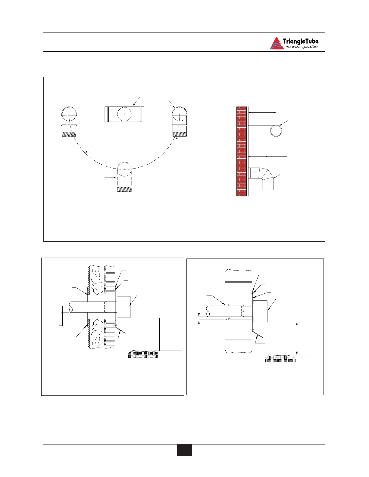
37
Venting and Combustion Air Installation
Fig. 24B: Vent Termination - Non-
Combustible Wall
Fig. 24A: Vent Termination Combustible
Wall
Fig. 23: Location of Air Inlet Termination - Direct Vent Horizontal Separate (2 pipe) installations
Location of Air Inlet
Not recommended for
Vertical Tee or Hooded
Vent Termination
Vent Termination Tee
12" Recommended
minimum clearance
Air Inlet Elbow
Location of Air Inlet
Not recommended for
Horizontal Tee Vent
Termination or
horizontal/straight-out
screened termination
Maximum 12"
Vent Termination
Maintain Distance as
Close to Outside Wall
as Possible
Combustion Air
Inlet
Caulk opening
Anchored fastners
Metal Plate
Vent Termination
2" Min.
clearance
Anchored
fastners
Flashing
recommended
to direct exhaust
away from wall
12" Min.
Grade level
Caulk opening
Anchored fastners
Cement
mortar
seal
1" Min.
clearance
Metal Plate
Vent Termination
Flashing
recommended
to direct exhaust
away from wall
12" Min.
Grade level
Page 45

38
Venting and Combustion Air Installation
Fig. 25: Horizontal Wall Thimble Kit - Termination Hood
Fig. 26: Horizontal Wall Thimble Kit - Termination Tee
Outside End Cap
Attach to outer wall
with combustion air inlet
using galvanized screws
openings facing downward
Box
Thimble
Inside End Cap
Apply high temp.
around vent pipe
silicon bead to seal
Vent Piping
to termination fitting
extend through thimble box
Split
Ring
Note: Use Locking Bands
inside the Thimble Box
against the inside and
outside End Caps to prevent
movement of the vent piping.
combustion
air inlet piping
3" to 4" reducer
Split Ring
to provide
may be used
- must vent horizontally
- must extend a minimum 6" beyond
Termination Tee
addition seal
Outside End Cap. DO NOT extend
more than 12"
Vent Piping
Note: Use Locking Bands
inside the Thimble Box
against the inside and
outside End Caps to prevent
movement of the vent piping.
Outside End Cap
Attach to outer wall
with combustion air inlet
using galvanized screws
openings facing downward
Box
Thimble
Inside End Cap
Apply high temp.
around vent pipe
silicon bead to seal
to termination fitting
extend through thimble box
Split
Ring
combustion
air inlet piping
3" to 4" reducer
Split Ring
to provide
may be used
- must vent horizontally
Termination Hood
addition seal
- attach to Outside End Cap
Page 46

39
Gas Piping
SECTION VII - Gas Piping
Gas Supply Piping Connection
The gas supply piping must be installed
in accordance to all applicable local,
state and national codes and utility
requirements.
1. Remove the burner jacket hood. Refer to
Figure 27 to pipe gas supply to the burner.
a. Install a pipe union at the factory sup-
plied gas nipple, for ease of service.
b. Install a manual shutoff valve in the gas
supply piping as shown in Figure 27.
For installations in Canada, the installer
must tag and identify the main shutoff
valve.
c. Install a drip leg on the gas supply line
prior to connecting to the PERFORMANCE gas train as shown in Figure 27.
2. Support the gas piping using hangers. Do
not support the piping by the unit or its
components.
3. Purge all air from the gas supply piping.
4. Before placing the PERFORMANCE into
operation, check and test all connections
for leaks.
Close the manual shutoff valve during
any pressure test with less than 13”w.c..
Disconnect the PERFORMANCE and
its gas valve from the gas supply piping
during any pressure test greater than
13”w.c..
Do not check for gas leaks with an open
flame. Use a gas detection device or bubble test. Failure to check for gas leaks
can cause severe personal injury, death
or substantial property damage.
5. Use pipe dope compatible with natural and
propane gases. Apply sparingly only to the
male threads of pipe joints so that pipe
dope does not block gas flow.
Failure to apply pipe dope as detailed
above can result in severe personal
injury, death or substantial property
damage.
Use a two-wrench method of tightening
gas piping near the unit and its gas valve.
Use one wrench to prevent the gas valve
line connection from turning and the second to tighten adjacent piping. Failure
to support the gas valve connection piping could damage the valve and the gas
line components.
WARNING
WARNING
WARNING
NOTICE
Fig. 27: Recommended Gas Supply Piping
Direction of flow
Equipment Shutoff valve
(must be within 6'
from the water heater)
Pressure gauge port
(1/8" NPT plugged)
Tee
3" Minimum
Drip leg
Male union
Burner gas train
Pipe Cap
Page 47

Gas Piping
40
Length of Pipe
in Feet
SCH 40 1/2" 3/4" 1" 1-1/4" 1-1/2"
10 132 278 520 1050 1600
20 92 190 350 730 1100
30 73 152 285 590 860
40 63 130 245 500 760
50 56 115 215 440 670
75 45 93 175 360 545
100 38 79 150 305 460
150 31 64 120 250 380
Capacity of Pipe in Cubic Feet of Gas Per Hour
(based on 0.60 specific gravity, 0.30" w.c. pressure drop)
Table 3: Gas piping sizing - Natural Gas
NATURAL GAS
Pipe Sizing - Natural Gas
1. Refer to Table 3 for pipe length and diameter requirements. Based on rated PERFORMANCE input (divide by 1,000 to
obtain cubic feet per hour).
-Table 3 is based on Natural Gas with a
specific gravity of 0.60 and a pressure
drop through the gas piping of
0.30”w.c..
- For additional gas piping sizing infor-
mation, refer to ANSI Z223.1. For
Canadian installations refer to B149.1
or B149.2.
Natural Gas Supply Pressure Requirements
1. Pressure required at the gas valve inlet
supply pressure port:
- Maximum 13”w.c. at flow or no flow
conditions to the burner.
- Minimum 5”w.c. during flow condi-
tions to the burner. Must be verified
during start up and with all gas appliances operating.
2. Install 100% lockup gas pressure regulator
in the gas supply line if inlet pressure can
exceed 13”w.c at any time. Adjust the lockup pressure regulator for 13”w.c maximum.
DO NOT adjust or attempt to measure
gas valve outlet pressure. The gas valve
is factory-set for the correct outlet pressure. This setting is suitable for natural
gas and propane and requires no field
adjustment. Attempts by the installer to
adjust or measure the gas valve outlet
pressure could result in damage to the
valve, causing potential severe personal
injury, death or substantial property
damage.
WARNING
Page 48

41
Gas Piping
Fig. 28: Gas Valve / Venturi Assembly
PROPANE GAS
Pipe Sizing - Propane Gas
1. Contact the local propane gas supplier for
recommended sizing of piping, tanks and
100% lockup gas regulator.
Propane Gas Supply Pressure Requirements
1. Adjust the propane supply regulator provided by the gas supplier for 13”w.c. maximum pressure
2. Pressure required at the gas valve inlet supply pressure port:
- Maximum 13”w.c. at flow or no flow
conditions to the burner
- Minimum 5”w.c. during flow condi-
tions to the burner. Must be verified
during start up and with all gas appliances operating.
DO NOT adjust or attempt to measure
gas valve outlet pressure. The gas valve
is factory-set for the correct outlet pressure. This setting is suitable for natural
gas and propane and requires no field
adjustment. Attempts by the installer to
adjust or measure the gas valve outlet
pressure could result in damage to the
valve, causing potential severe personal
injury, death or substantial property
damage.
Prior to start up, ensure the unit is set to
fire propane. Check the rating label for
the type of fuel. Check the gas valve and
air inlet for propane conversion labels.
If there is a conflict or doubt on the
burner set up, remove the gas valve and
check for the propane orifice. Failure to
ensure proper burner setup could result
in severe personal injury, death or substantial property damage.
WARNING
WARNING
Venturi
Propane
Orifice
Gas Valve
Inlet Supply
Pressure Port
Gas Valve
Gas Valve
Pipe Fitting
Gasket
Page 49

42
Internal Wiring
Fig. 29 : Burner Control Wiring
SECTION VIII - Internal Wiring
ELECTRICAL SHOCK HAZARD. For
your safety, disconnect electrical power
supply to the unit before servicing or
making any electrical connections to
avoid possible electric shock hazard.
Failure to do so can cause severe personal injury or death.
All electrical contacts shown in Figures
30 & 31 pages 43 & 44 do not have electrical power applied. Shown as “offshelf” condition.
General Requirements
-Wiring must be N.E.C Class 1.
- If original wiring installed in the unit
must be replaced, use only type T, 90ºC
wire or equivalent.
- The PERFORMANCE must be electrically grounded as required by National
Electrical Code ANSI/NFPA 70 - latest
edition.
NOTICE
WARNING
ELECTRONIC
CONTROLS
SERIES
1016-400
1
Blower
Molex Plug
LED
Indicator
L
White
Green
N
L1
Snap-Set
MV
IND
LED
Black
Gas Valve Plug
Air Switch
Terminals
PS
2
Black
PS1
W
R
FS
Red
Snap-Set
ANSI Z
IGNITORSPARKDIRECT
HV
X C/COM
T1
21.20
Black Gas Valve Plug
Red Snap-Set T2
Page 50

43
Internal Wiring
Fig. 30: Factory Wiring Schematic
Room T -Stat
Snap-Set
1
C
B
Relay R2
BL
1
3
B
6
4
T
T
B
BL
B
Relay R1
1
4
BL
LWCO
B
3
6
V
R
BL
Burner
Snap-Set
N
L1
B
R
B
W
Transformer
BL
Circulator
120V Field Wiring (By Others)
120V Factory Wiring
B
W
Y
24V Factory Wiring
B - Black
B
W
BL - Blue
P - Pink
V - Violet
G
Y
Y - Yellow
R - Red
OR - Orange
T - Tan
W- White
B
V
T
87 65
9
10
12 11
T
Y
BL
OR
GG
14 13
B
R
B
B
V
Y
432
P
P
1
G
G
Y
V
W
G
G
B
G
120 V Incoming
N
Supply Wiring
H
C
1
2
Secondary T-Stat
Snap-Set
B
T1 T2
Burner
Manual Reset
Safety Limit
C
2
Auto Reset
Safety Limit
On-Off
Switch
1
C
Primary T-Stat
1
2
Page 51

44
Internal Wiring
Fig. 31: Factory Internal Wiring
Y
B
B
LWCO
Jumper
On-Off
Switch
Manual
Reset
Limit
B
R
R2A
R1A
B
R
120 VAC
B
Burner Control
B
120V
24V
Y
Secondary
T-stat
Circulator
Y
B
L1
B
BRN
B
R
BL
IND
MV
PS2
R
PS1
C
C
CDM
Blower
Equipment
Ground
W
B
Air Switch
Gas Valve
W
BL
Alarm
Room T-stat
Snap-set
B
B
OR
T
T
V
R2
BL
P
P
V
V
Primary
T-Stat
V
BL BL
R2B
Auto
Reset
Limit
Burner Control
B
R
Factory
Jumper
B - Black
BL - Blue
P - Pink
V - Violet
Y - Yellow
R - Red
OR -Orange
T - Tan
W- White
Page 52

45
External Wiring
SECTION IX - External Wiring
Installation Compliance
All field wiring made during installation must
comply with:
- National Electrical Code NFPA 70 and
any other national, state, provincial or
local codes or requirements.
- In Canada, CSA C22.1 Canadian
Electrical Code Part 1, and any other
local codes.
Line Voltage Connections
1. Connect 120 VAC power wire to the line
voltage leads located behind the front control panel.
2. Route the incoming 120 VAC power wire
through the right side jacket panel.
3. Use the wire nuts provided to ensure a tight
and secure connection.
4. The unit is provided with a service
switch. Check local code requirements for
compliance.
If local electrical codes or conditions
require an additional service switch, the
installer must provide and install a fused
disconnect or 15 amp (minimum) service
switch.
Thermostat Wiring
1. Connect room thermostat or the end switch
(isolated contact only) of a relay control
panel to the Room Thermostat Snap-set
located on the rear jacket panel.
2. Remove the snap-set cover and connect the
thermostat wiring to terminals C and 1 per
Figure 32.
3. For proper operation, install the room thermostat on an inside wall away from influences of heat and cold, i.e. water pipes,
areas of draft, lighting fixtures and fireplaces.
4. Set the thermostat anticipator (if applicable) as follows:
- Set for 0.2 amps when wired directly to
the Room Thermostat Snap-set.
- Set to match the total electrical power
requirements of the connected devices
when wired to zone relays or other
devices. Refer to the relay manufacturers’ specifications and the thermostat
instructions for additional information
on the anticipator setting.
Outdoor Temperature Limit
1. The PERFORMANCE may operate with a
variable primary operating temperature
using an outdoor reset control provided by
the installer.
2. Remove the factory jumper across terminals 9 and 10 see Figs. 30 & 31, on pages
43 & 44. Connect the outdoor limit control
to those terminals.
3. Set the operating limits of the outdoor limit
control as follows:
- Maximum operating temperature of
180ºF.
– Minimum operating temperature of
150ºF.
4. Set the primary thermostat to the highest
possible setting.
NOTICE
Fig. 32: Room Thermostat Snap-set Wiring
Page 53

External Wiring
46
4 Wire Zone Valve
Fig. 33: Multiple Zone Field Wiring Using Zone Valves
3 Wire Zone Valve
*Use isolation relay on 3-wire
zone valve with non-isolated
end switch. Transformer and
the PERFORMANCE control
can burn out if isolation relay is
not used.
Additional zones
Zone 1
Zone 2
H
Transformer
(Power)
Room
Thermostat
Room
Thermostat
Additional zones may
be added as shown above
120
V.A.C.
24
V.A.C.
Zone
Valve
N
High Voltage
Zone Valve
1
C
To PERFORMANCE
"Room Thermostat"
Snap Set
Additional zones
Zone 1
Zone 2
H
V.A.C.
Transformer
(Power)
V.A.C.
Room
Thermostat
Room
Thermostat
Zone
Valve
Additional zones may
be added as shown above
120
24
N
High Voltage
Zone Valve
* Isolation relay
1
C
To PERFORMANCE
"Room Thermostat"
Snap Set
Page 54

47
External Wiring
Fig. 34: Field wiring with zone circulators.
120
H
VA C
N
Honeywell
R845A
Relay
Circulator
Zone 1
Circulator
Zone 2
TT
T
T
1
2
T
T
1
2
Thermostat
zone 1
4
3
Thermostat
zone 2
4
3
5
6
5
6
Additional zones may be
added as shown above
To PERFORMANCE
" Room Thermostat"
1
C
Snap Set
Page 55

48
External Wiring
Fig. 35: Typical Zone Relay Panel Wiring
Fig. 36: Storage Tank Recirculation Wiring
N
120V
H
C
To PERFORMANCE
"Room Thermostat"
Snap-Set
Thermostat
Zone 1
R
C
T1 T1 T2T2 T3 T3
X2X1L1L2 ZC
1
Zone 1
Circulator
Thermostat
Zone 2
C2C2C1C1PRPR
Zone 2
Circulator
Thermostat
Zone 3
C3
C3
Zone 3
Circulator
120
VA C
H
N
TT
T
T
1
2
Bronze
Circulator
Storage Tank
Thermostat
4
3
Honeywell
R845A
Relay
5
6
Page 56

49
Start-Up Preparation
SECTION X - Start Up Preparation
Check System and Domestic Water
Chemistry
Do not use petroleum-base cleaning or
sealing compounds in the primary system. Damage to seals and gaskets in the
system components could occur, resulting in substantial property damage.
System water including additives must be
practically non-toxic, having a toxicity
rating or Class of 1, as listed in Clinical
Toxicology of Commercial Products.
Water pH Level 6.0 to 8.0
Maintain the primary system water pH
between 6.0 and 8.0. Check using litmus
paper or contact a water treatment company for a chemical analysis.
If the pH does not meet this requirement,
do not operate the PERFORMANCE or
leave the unit filled until the condition is
corrected.
Water Hardness Less Than 7 Grains
For areas with unusually hard water (hardness above 7 grains) consult a water treatment company.
Chloride Concentration Less Than 80 mg/L
For those installations that use a water softener or conditioner, consult the water treatment company.
Any water conditioning system must
be installed and maintained in accordance with the water conditioner’s
manufacturer’s specifications and
within the operating guidelines of the
PERFORMANCE.
Chlorinated Water
Do not use the PERFORMANCE inner or
outer tank to heat a swimming pool or spa
directly.
Maintain the chlorine level of the water in
the inner and outer tanks at levels considered safe for drinking.
Flush Primary and Domestic System to
Remove Sediment
The installer must flush both the primary
and domestic system to remove any sediment to allow proper operation of the PERFORMANCE.
Flush the systems until the water runs clean
and is free of sediment.
For primary zoned systems, each zone
should be flushed through a purge valve.
Purge valves and isolation valves should be
installed on each zone to allow for proper
flushing of the system.
Check and Test Antifreeze
For primary systems containing antifreeze
solutions, follow the antifreeze manufacturer’s instructions in verifying the
inhibitor level and to ensure the fluid characteristics are within specification requirements.
Due to the degradation of inhibitors over
time, antifreeze fluids must be periodically
replaced. Refer to the manufacturer of the
antifreeze for additional instructions.
NOTICE
NOTICE
WARNING
Page 57

50
Start-Up Preparation
System water, including additives must be
practically non-toxic, having a toxicity
rating or Class of 1, as listed in Clinical
Toxicology of Commercial Products.
Use of Antifreeze in the Primary System
NEVER use automotive or ethylene glycol antifreeze or undiluted antifreeze in
the primary system as freeze protection.
This can cause severe personal injury,
death or substantial property damage if
ignored.
Determine the antifreeze fluid quantity
using the system water content volume and
following the antifreeze manufacturer
instructions.
The primary outer tank volume of the PERFORMANCE is 20 gallons. Remember to
include the volume of the expansion tank.
Check with local codes requirements for
the installation of back flow preventers or
actual disconnect from the make up water
supply line.
Ensure the concentration of antifreeze to
water does not exceed a 50/50 ratio.
System water including additives must be
practically non-toxic, having a toxicity
rating or Class of 1, as listed in Clinical
Toxicology of Commercial Products.
Filling the Inner (Domestic) Tank and
System
Proceed with filling instructions for the
inner and outer tanks only after ensuring the water meets the requirements
listed in this installation manual. Failure
to comply could result in damage and
improper operation of the unit.
Never operate the PERFORMANCE
unless both the inner and outer tanks are
completely filled.
Always fill the inner tank prior to filling
and pressurizing the outer tank. Failure
to properly fill the inner tank could
result in damage to the inner tank.
1. Ensure the domestic drain valve is closed.
2. Open the isolation valves on the domestic
cold supply piping to the PERFORMANCE and on the domestic hot outlet
piping to the building (if provided).
3. Vent any air from the domestic piping system by opening faucets near the unit.
Continue filling the domestic system until
there is a constant flow of water from the
faucets.
4. Close the hot water faucets.
Filling the Outer (Primary) Tank and
System
1. Close the primary drain valve located on
the rear of the unit and any manual or automatic air vent in the system.
2. Open all system isolation valves.
CAUTION
CAUTION
WARNING
NOTICE
WARNING
NOTICE
Page 58

51
Start-Up Preparation
3. Fill the outer tank to correct system pressure. Correct pressure will vary with each
application.
Typical residential system fill pressure is
12 psi. System pressure will increase
when system temperature increases.
Operating pressure of the system should
never exceed 25 psi.
4. Allow air to escape from the outer tank by
opening the automatic air vent provided
with the PERFORMANCE.
5. Purge air in each zone of the primary system through the purge valve. Open air
vents to allow air to be purged in the zones.
6. Once the system is completely filled and
purged of all air, check the system pressure
and check for leaks.
Check Low Water Cut-Off Device
- The PERFORMANCE is provided with
a factory installed Low Water Cut-Off
device that measures system pressure
of more than 10 psi.
- Remove the front jacket panel and check
for continuity across the low water cutoff device wire terminals. The contacts
should be closed when system pressure
is greater than 10 psi.
Check For Gas Leaks
Prior to start-up and during initial operation, smell near the floor and around the
unit for gas odorant or any unusual odor.
Do not proceed with the start-up if there
is any indication of a gas leak. Any leaks
found must be repaired immediately.
DO NOT adjust or attempt to measure
gas valve outlet pressure. The gas valve
is factory-set for the correct outlet pressure. This setting is suitable for natural
gas and propane and requires no field
adjustment. Attempts by the installer to
adjust or measure the gas valve outlet
pressure could result in damage to the
valve, causing potential severe personal
injury, death or substantial property
damage.
Propane installations only - The propane
supplier mixes an odorant with the
propane to make its presence detectable.
In some cases the odorant can fade and
the gas may no longer have an odor.
Prior to start-up of the unit and periodically after start-up, have the propane
supplier check an verify the odorant
level.
WARNING
WARNING
WARNING
NOTICE
Table 4 : Pressure Switch Setting
PG Model Natural Gas Propane
(inch w.c.) (inch w.c.) Natural Gas Propane
(inch w.c.) (inch w.c.)
PG-25 1.84 " w.c. 3.35" w.c. n/a n/a
PG-30 1.84 " w.c. 3.35" w.c. 2.7" w.c. 3.35" w.c.
PG-35 1.84 " w.c. 3.35" w.c. 3.35" w.c. 3.35" w.c.
PG-40 2.7 " w.c. 3.35" w.c. 2.7 " w.c. 3.35" w.c.
PG-45 2.7 " w.c. 3.35" w.c. 2.7 " w.c. 3.35" w.c.
High Altitude
(Above 5,000 feet)
Pressure Switch Identification:
- YELLOW Label: 1.84”w.c.
- RED Label: 2.7” w.c.
- BLUE Label: 3.35 w.c
n/a -Models not available.
Page 59

52
Start-Up Preparation
Verify Correct Pressure Switch
1. Remove the burner hood and verify the
burner pressure switch setting.
2. Check and compare the color of the outline on the pressure switch label to Table
4 page 51.
The PERFORMANCE is equipped with
an air pressure switch, which provides a
safe means of shutting down the unit due
to a blockage of the combustion air inlet.
The switch is “normally closed” and
measures the change in the negative
pressure (vacuum) created by the burner blower.
Verify Correct Air Shutter Setting
- Check and verify the air shutter setting
as listed in Table 5.
- The air shutter is located inside the com-
bustion air inlet adapter located in the
top /left jacket panel area. See Fig. 37.
Check Thermostat Circuit
- Unplug the Room Thermostat Snap-set
located on the rear of the unit.
- Connect a voltmeter across the end ter-
minals of the male half of the Room
Thermostat Snap-set.
- Close each thermostat, zone valve and
relay in the external circuit one zone at
a time and check the voltage reading
across the plug.
- There should NEVER be voltage measured at the plug.
- If voltage is measured at the plug under
any condition, check and correct the
external wiring.
In systems using 3-wire zone valves
backfeed of voltage to the unit is a common problem. Use an isolation relay to
prevent voltage from the external circuit
entering the Room Thermostat Snap-set.
See Fig. 33, page 46.
NOTICE
NOTICE
Table 5 : Air Shutter Settings
Fig. 37: Air Shutter Adjustment
Model Natural gas Propane
Natural gas Propane Natural gas Propane Natural gas Propane
PG-25 N/R 3.5 n/a n/a n/a n/a n/a n/a
PG-30 N/R 3.5 4.5 4.5 2.5 4.0 n/a n/a
PG-35 N/R 3.5 4.5 3.5 3.5 3.75 n/a n/a
PG-40 N/R 0 2 0 0 0 n/a n/a
PG-45 N/R 0 0 0 0 0 0 0
9,000 feet elevation
8,000 feet elevation
5,000 feet elevation
n/a -Models not available.
N/R - Air Shutter not required. (For these units an adjustable air shutter is NOT supplied with the unit.)
Page 60

53
Start-Up Procedures
SECTION XI - Start-Up Procedures
Final Checks Before Start-up
Verify the PERFORMANCE and the
primary and domestic systems are full
of water and all system components are
correctly set for operation.
Verify Start-up Preparation items outlined
on pages 49 thru 52 have been completed.
Verify all electrical connections are
correct and securely fasten.
Inspect vent piping and combustion air
inlet piping for signs of deterioration from
corrosion, physical damage or sagging.
Verify combustion air piping and vent piping are intact and correctly installed.
Verify Burner Configuration - Propane
Only.
Check for proper labeling on the gas
valve, combustion air inlet and the rating label for propane configuration.
If there is doubt on the burner configuration, remove the gas valve and check
for proper propane orifice. See Fig. 28
page 41. Refer to Propane Conversion
Instructions for additional information
on assembly of the gas valve.
Adjustment of the Secondary Thermostat
Limit.
The Secondary (Domestic) Thermostat
located on left side of the control panel
maintains the minimum domestic water
storage temperature.
Set the thermostat knob as shown in
Fig. 38 page 56.
Maximum limit setting is 140ºF
PERFORMANCE Start-up
1. Turn the ON-OFF switch located on the front
control panel to the OFF position. Turn the
electrical supply or any external service
switch to the unit in the ON position.
2. Read and follow the Operating Instructions
outlined on page 54 to start the appliance.
If PERFORMANCE Does Not Start Correctly
1. Check for loose electrical connections,
blown fuse or open service switch.
2. Check continuity across the Low Water
Cut-Off device for close circuit.
3. Is the manual limit control open? Ensure the
manual limit is reset to the close position.
4. Is the gas supply valve open at the unit and
meter?
5. Is incoming gas supply pressure more than
5”w.c. for natural or propane with all gas
appliances operating.
6. Are the heating thermostats set below room
temperature?
If none of these conditions correct the problem,
refer to the PERFORMANCE Trouble-shooting guide.
Check the PERFORMANCE and System
Check Domestic Piping.
Check domestic piping and system
components for leaks. If found, shut
down the unit and repair immediately.
Check Primary Piping.
Check primary system piping and components for leaks. If found, shut down
the unit and repair immediately.
Purge any remaining air from the system
piping. Air in the system piping will
interfere with circulation creating heat
distribution problems and system noise.
Check Vent Piping and Combustion Air
Piping.
Check for gas-tight seal at every connection and seam of the venting and
combustion air inlet.
Page 61

54
Start-Up Procedures
FOR YOUR SAFETY READ BEFORE LIGHTING
OPERATING INSTRUCTIONS
TO TURN OFF GAS TO APPLIANCE
1. STOP! Read the safety information above.
2. Set the secondary thermostat to the lowest
setting.
3. Turn manual shutoff valve on the gas supply
line clockwise to “Close”
4. Set the unit’s “ON-OFF” switch to “OFF”
5. This appliance is equipped with an ignition
device which automatically lights the pilot.
Do not try to light the pilot by hand.
6. Turn manual shutoff valve on the gas supply
line counter clockwise to “Open”
7. Wait five (5) minutes to clear out any gas. If
you smell gas, STOP! Follow “B” in the
safety information stated above. If you don’t
smell gas, go to next step.
8. Set the unit’s “ON-OFF” switch to “ON”
9. Set the secondary thermostat to the desired setting. See Page 56 for recommended thermostat
settings.
10. If the appliance will not operate, follow the
instructions “To Turn Off Gas To Appliance”
and call your service technician or gas supplier.
WARNING
The following instructions must be followed exactly, a fire or
explosion may result causing property damage, personal injury
or loss of life.
1. Set the system thermostat to lowest setting.
2. Turn the unit’s “ON-OFF” switch to “OFF”
3. Turn manual shut-off valve on the gas supply
line clockwise to “Close”.
A. This appliance is equipped with an electron-
ic ignition system. Do not attempt to light
the burner by hand.
B. BEFORE OPERATING, smell all around the
appliance area for gas. Be sure to smell next
to the floor because some gas is heavier than
air and will settle on the floor.
WHAT TO DO IF YOU SMELL GAS
• Do not try to light any appliance.
• Do not touch any electric switch; do not
use any phone in your building
•Immediately call your gas supplier from a
nearby phone. Follow the gas supplier’s
instructions.
• If you cannot reach your gas supplier, call
the fire department.
C. Do not use this appliance if any part has been
under water. Immediately call a qualified
service technician to inspect the appliance
and to replace any part of the control system
and any gas control which has been under
water.
Page 62

55
Start-Up Procedures
Venting system must be sealed gas-tight
to prevent flue gas spillage and potential
carbon monoxide emissions, which will
result in severe personal injury or death.
Check Gas Piping
Check around the unit for gas odor following the procedure outlined in this
manual on Page 51.
If any gas leaks are found or suspected,
shut the unit down immediately. Use a
gas detection device or bubble test to
locate the source of the gas leak and
repair at once. Do not operate the unit
until the leak is corrected. Failure to
comply with this procedure could result
in severe personal injury, death or substantial property damage.
Verify Flame Pattern and Combustion
Check the flame pattern through the
inspection port of the burner. The
flame should be blue and stable. The
flame should be the length of the burner head openings.
Remove the test plug located on the flue
hood and insert a combustion test probe.
Test for CO2 or O2 and for CO. The
combustion reading should be within
the range listed in Table 6. The CO
level should not exceed 100 ppm when
combustion is correct.
To adjust the combustion level open or
close the air shutter by a 1/2 setting.
- Closing the air shutter will decrease
the O2 level and increase the CO2
level.
- Opening the air shutter will increase
the O2 level and decrease the CO2
level.
A combustion test must be performed
after any adjustments are made. Allow
the unit to operate for approximately 10
minutes after adjustment before measuring any combustion levels. Failure to
comply with these procedures could
result in severe personal injury, death or
substantial property damage.
Replace the test port plug when the combustion test is completed to prevent flue
gas spillage into the building. Failure to
comply with this procedure could result
in severe personal injury, death or substantial property damage.
Measure Input - Natural Gas Only
1. Operate the unit for approximately 10
minutes.
2. Turn off all gas appliances within the
building.
3. At the gas meter, record the time
required to use one cubic foot of gas.
4. Calculate gas input using the following
equation:
3600 x 1000 / number of second recorded for one cubic of gas = BTU/H.
5. The BTU/H calculated should approximate the input rating listed on the unit.
WARNING
WARNING
WARNING
WARNING
Natural Gas Propane
O2 Min. 3.00% 3.00%
O2 Max. 5.00% 5.00%
CO2 Min 9.00% 10.50%
CO2 Max 10.00% 12.00%
Table 6: Recommended Combustion Levels
Page 63

56
Temperature Limits
SECTION XII - Temperature Limits
Studies have indicated that dangerous
bacteria can form in the potable water
distribution system if certain minimum
water temperatures are not maintained.
For prevention of this, it is recommended that the Secondary Thermostat be set
as shown in Figure 38 and maintained at
130ºF to 140ºF.
Setting Primary Thermostat Limit.
- The Primary (Space Heating) Thermostat
located on the right side of the control
panel acts as the high limit during the
space heating function.
- Set the thermostat knob as shown in
Figure 39.
- Maximum limit setting is 180ºF
To ensure proper function of the limits
the Primary Thermostat must be set
higher than the Secondary Thermostat.
Adjustment of Secondary Thermostat Limit
- The Secondary (Domestic) Thermostat
located on left side of the control panel
maintains the minimum domestic water
storage temperature.
- Set the thermostat knob as shown in
Figure 38.
- Maximum limit setting is 140ºF.
To adjust the thermostat settings:
-Turn thermostat knob clockwise
to increase water temperature
-Turn thermostat knob counter-
clockwise to decrease water
temperature.
NOTICE
NOTICE
DANGER
Fig. 38: Recommended Secondary
Thermostat Setting
Fig. 39: Recommended Primary Thermostat
Setting
Temperature Indicator
Temperature UpTemperature Down
e
m
s
t
o
i
c
D
g
e
a
s
h
e
P
n
Back
Plate
c
i
a
t
a
p
e
S
h
I
I
-
I
I
-
I
I
e
s
a
h
P
h
a
s
e
P
I
I
-
I
I
-
P
I
I
h
a
e
s
Knob
Temperature Indicator
Temperature UpTemperature Down
a
c
p
e
S
t
a
i
n
e
g
h
D
e
I
I
o
s
I
a
-
Back
Plate
h
P
-
I
I
I
e
s
a
h
P
-
I
I
m
P
h
e
a
s
s
t
e
i
c
I
I
I
-
P
h
a
I
s
e
Knob
Page 64

57
Temperature Limits
Setting the Thermostatic Mixing Valve
The thermostatic mixing valve controls
the outlet hot water temperature delivered to the faucets.
POTENTIAL SCALD HAZARD The
mixing valve must be installed on the
PERFORMANCE. Removal of the mixing valve will create a potential scald
hazard resulting in severe personal
injury or death.
- Use a L-Key to remove the set screw
securing the knob to the valve.
- Remove the knob and lock ring from
the valve.
- Replace the knob and adjust the set
temperature of the valve to the desired
temperature.
To calibrate the outlet temperature,
allow the water to run for approximately
2 minutes and measure the water with a
thermometer. To adjust the valve setting,
rotate the knob clockwise to decrease the
water temperature or counter-clockwise
to increase the water temperature.
- Once the desired temperature is
achieved, remove the knob and refit the
lock ring onto the valve aligning the
ring indicator mark with the valve’s
“Mix” marking.
- Locate the tab on the inner face of the
knob into the retainer in the locking
ring. Secure the knob with setscrew.
- Record the valve performance on the
Installation Record included in this
manual.
For proper operation of the thermostatic
mixing valve, the manual valve on the Utube assembly MUST remain open to
avoid a potential scald hazard.
DANGER
NOTICE
WARNING
NOTICE
Page 65

58
Check-Out Procedures
SECTION XIII- Check-Out Procedures
Perform the following check-out procedures as outlined and check off items as
completed. When procedures are completed, the installer should complete the
installation record on page 59.
Check-out Procedures
Both inner and outer tanks filled with
water.
Water chemistry checked and verified
as outlined on page 49.
The automatic air vent on the unit and
any place within the system are open
one full turn.
Air is purged from the heating zones
and primary system.
Domestic piping is purged of air and
has been checked for leaks.
Burner has been confirmed as properly
configured for Propane application. (If
applicable).
Thermostat circuit wiring checked and
verify that no voltage is present at the
Room Thermostat Snap-set as outlined
on page 52.
Operating Instructions on page 54 were
followed during start-up.
Combustion levels and flame pattern
verified as outlined on page 55.
Measure the rate of input on Natural
Gas as outlined on page 55.
Check the incoming gas pressure to
ensure a minimum pressure of 5”w.c
during flow conditions to all appliances
and a maximum pressure of 13”w.c
during non-flow conditions for Natural
and Propane.
Primary and Secondary Thermostat
properly set as shown in Figure 38 and
39 page 56.
The thermostatic mixing valve adjusted
to the desired domestic hot outlet temperature.
Adjusted balancing valves and system
limit controls to provide design temperatures to the primary space heating system.
In multiple zone applications, adjusted
for correct flow of primary heating
water to each zone.
Check and verify room thermostats
functions properly and the thermostats
heat anticipator (if used) was properly
set.
Observed several operating cycles for
proper operation of the PERFORMANCE and the system.
Set the room thermostat(s) to the
desired room temperature.
Reviewed all instructions shipped with
the PERFORMANCE with the homeowner or maintenance personnel.
Complete the Installation Record on
page 59.
Ensure all manuals and other documen-
tation are returned to the Installation
envelope and given to the owner for
safekeeping.
NOTICE
Page 66

59
Installation Record
SECTION XIV - Installation Record
PRESTIGE Model Number:
Serial Number:
Date of Installation:
Fuel: Natural Gas Propane
Measured Rate of Input:
Btu/hr
Combustion Readings:
2
CO
O2
CO
%
%
ppm
The following items were completed during installation:
Installation instructions have been followed and completed
Check-out procedures have been followed and completed
Information regarding the unit and installation received and left with owner / maintenance
personal.
Installer Information
(Company)
(Address)
(Address)
(Phone Number)
____________________________________________________________________
____________________________________________________________________
____________________________________________________________________
_________________________________________________________________
Page 67

60
Maintenance Schedule
SECTION XV - Maintenance Schedule
Service Technician
At least on an annual basis the following maintenance should be performed by a qualified service technician:
General
• Attend to any reported problems.
• Inspect the interior of the combustion
chamber; clean and vacuum if necessary.
• Clean the condensate trap in the vent
system and fill with fresh water.
• Check for leaks; water, gas, flue and
condensate.
•Verify flue vent piping and air inlet piping are in good condition and sealed
tight.
• Check primary system water pressure/
primary system piping/primary expansion tank.
• Check domestic water pressure/domestic system piping/domestic thermal
expansion tank.
• Check domestic and primary thermostat settings.
• Check ignition electrode (sand off any
white oxide; clean and reposition).
• Check ignition wiring and ground
wiring.
• Check all control wiring and connections.
• Check burner flame pattern (stable and
uniform) and flame.
Additional items if combustion or performance
is poor:
• Clean baffles and flue ways.
• Remove burner assembly and clean
burner head using compressed air only.
Once the maintenance items are completed,
review the service with the owner.
Owner Maintenance
Daily:
• Check the area around the unit.
• Check the combustion air inlet and ventilation openings for blockage.
• Check the temperature/pressure gauge.
Monthly:
• Check vent piping.
• Check combustion air inlet piping.
• Check the pressure relief valve.
• Check the temperature/pressure relief
valve.
• Check the vent condensate drain system.
• Check the automatic air vents in the primary system.
Every 6 months:
• Check both primary piping and gas
supply piping for corrosion or potential
signs of leakage.
• Operate the pressure relief valve.
• Operate the temperature/pressure relief
valve.
Periodically:
• Check the operation of the domestic
mixing valve.
Follow the maintenance procedures
given throughout this manual. Failure
to perform the service and maintenance
or follow the directions in this manual
could result in damage to the PERFORMANCE or in system components,
resulting in severe personal injury, death
or substantial property damage.
WARNING
Page 68

61
Maintenance Schedule
SECTION XVI - Maintenance
Procedures
MAINTENANCE PROCEDURES
The PERFORMANCE should be
inspected and serviced annually, preferably at the start of the heating season, by
a qualified service technician. In addition, the maintenance and care of the
unit as outlined on page 60 and further
explained on pages 61 through 64 should
be performed to assure maximum efficiency and reliability of the unit. Failure
to service and maintain the PERFORMANCE and the system components
could result in equipment failure, causing possible severe personal injury,
death or substantial property damage.
The following information provides
detailed instruction for completing the
maintenance items outline in the maintenance schedule on page 60. In addition
to this maintenance, the PERFORMANCE should be serviced at the beginning of the heating season by a qualified
service technician.
Reported Problems
Any problems reported by the owner
should be checked, verified and corrected
before proceeding with any maintenance
procedures.
Check the Surrounding Area
Verify that the area surrounding the PERFORMANCE is free of combustible / flammable materials or flammable vapors or
liquids. Remove immediately if found.
is free of any contaminates. Refer to the list of
potential materials listed on page 7 of this
manual. If any of these products are in the
room from which the unit takes its combustion air, they must be removed immediately or the combustion air intake must be
relocated to another area.
Inspect the Burner Area
Remove the burner hood and inspect the
appearance of the burner components.
Vacuum any dirt or debris from the burner
components.
Remove the venturi inlet elbow to check for
dirt and debris. Remove any obstructions.
Do not use solvents to clean any of the
burner components. The components
could be damaged, resulting in unreliable or unsafe operation.
Check System (Primary and Domestic)
Piping
Inspect all piping on the Primary Heating
system and the Domestic system for leaks
and verify that the piping is leak free.
Inspect the fittings and components on the
unit and verify they are leak free.
Eliminate all primary water system leaks.
Continual fresh make-up water will
reduce the outer tank life causing tank
failure. Leaking water may also cause
severe property damage to the surrounding area.
WARNING
WARNING
NOTICE
WARNING
Page 69

62
Maintenance Procedures
Check Combustion/ Ventilation Air Openings
Verify that all combustion air and ventilation openings to the mechanical room or
building are open and unobstructed. Check
the operation and wiring of any automatic
ventilation dampers.
Check and verify the vent discharge and the
combustion air intake are free of debris and
obstructions.
Inspect Vent System and Combustion Air
Piping
Visually inspect the venting system and
combustion air piping (if installed) for
blockage, deterioration or leakage. Repair
any vent joints that show signs of deterioration as per the vent manufacturer’s
instructions.
When combustion air is ducted to the unit,
verify that the air inlet piping is connected
and sealed. Inspect the air hose connecting
the air inlet adapter to the venturi elbow for
deterioration.
Failure to inspect the vent system and
combustion air inlet piping and have any
deficiencies repaired, can result in severe
personal injury or death.
Check Primary System
Verify all system components are correctly
installed and operating correctly.
Check the cold fill pressure for the system.
Typical cold water fill pressure is 12 psig.
Verify the system pressure as the unit operates at high temperature to ensure the pressure does not exceed 25 psig. Excessive
pressure reading indicates expansion tank
sizing is incorrect or system performance
problems.
Inspect air vent and air separators in the
system. Remove the caps on automatic air
vents and briefly depress the valve stem to
flush vent. Replace the cap when completed. Ensure vents do not leak, replace any
leaking vents.
Check Domestic System
Ve rify all system components are correctly
installed and operating correctly.
Check the outlet domestic temperature of
the mixing valve and compare with the
recorded temperature made during start-up.
Check Expansion Tank
Refer to Section V - Primary Piping for
recommended location of the expansion
tank and air eliminators.
Close -Type Tank:
- Ensure tank is partially filled with
water leaving an air gap as a cushion.
Refer to the manufacturer’s instruction
for proper fill level.
- Ensure the tank is fitted with a device
that reduces gravity circulation of airsaturated tank water back into the system. This device prevents air from
bubbling up through the water as it
returns from the system.
- Ensure no automatic air vents are used
in the system. This will allow air to
escape from the system instead of
returning to the tank.
Diaphragm Tank:
- Ensure the system contains a minimum
of one automatic air vent. Preferred
location of the air vent should be atop
an air eliminator.
- Remove the tank from the system and
check the charge pressure. For residential applications the charge pressure is
typically 12 psig. If tank does not hold
a charge pressure, then the membrane is
damaged and the tank should be
replaced.
WARNING
Page 70

63
Maintenance Procedures
Check Boiler Relief Valve
Inspect the relief valve and lift the lever to
verify flow at least annually or as recommended on the warning tag of the valve.
Before manually operating the pressure
relief valve, ensure the discharge piping is
directed to a suitable place of disposal to
avoid a potential scald hazard. The discharge piping must be full size without
restriction and installed to permit complete drainage of both the valve and line.
If after closing the valve, the valve fails to
seat properly or continually weeps, replace
the relief valve. Ensure the cause of the
relief valve to weep is the valve itself, not
due to system over-pressurization caused
by an expansion tank that is waterlogged or
undersized.
Check Temperature / Pressure Relief Valve
Inspect the T&P relief valve and lift the
lever to verify flow at least annually or as
recommended on the warning tag of the
valve.
Before manually operating the pressure
relief valve ensure the discharge piping is
directed to a suitable place of disposal to
avoid a potential scald hazard. The discharge piping must be full size without
restriction and installed to permit complete drainage of both the valve and line.
If after closing the valve, the valve fails to
seat properly or continually weeps, replace
the relief valve. Ensure the cause of the
weeping is the valve itself and not due to
thermal expansion or a faulty or underpressurized thermal expansion tank.
Inspection of Ignition Electrode
Remove the ignition electrode from the
burner mounting plate.
Remove any white oxides accumulated on
the electrode using fine grit sandpaper or
steel wool. If the electrode does not clean to
a satisfactory condition, replace the ignitor.
When replacing the ignition electrode,
ensure the gasket is in good condition and
correctly positioned.
Check Ignition Wiring and Ground Wiring
Inspect the burner wiring from the burner
control module to the ground terminal
behind the control panel.
Ensure wiring is in good condition and
securely connected.
Check ground continuity of the wiring
using a continuity meter.
Replace and correct ground wire if ground
continuity is not completed and satisfactory.
Check Control Wiring
Inspect all control wiring located behind
the control panel and at the burner control
module. Ensure wiring is in good condition and properly connected.
Check Thermostat Limit Settings
Check the position of the Secondary and
Primary Thermostat knobs, refer to Figure 38
and 39 page 56 for recommended settings.
Perform Start-up and Checkout Procedures
Start the unit and perform the start-up procedure as listed in this manual.
Verify the cold water fill pressure is correct
and the operating pressure of the primary
system is within normal operating range.
Complete the checkout procedures as referenced in this manual.
WARNING
WARNING
Page 71

64
Maintenance Procedures
Check Burner Flame
Inspect the burner flame through the observation port on the burner mounting plate.
If flame pattern is not fully blue and covers
the entire burner surface, shut the unit
down and allow it to cool thoroughly.
Close the manual gas valve on the gas supply line and disconnect the gas piping to
remove the burner assembly from the unit.
Remove the burner head mounting screws
and remove the burner head. Inspect the
head for deterioration. Use compressed air
or a vacuum to clean the burner head.
Remove the venturi and gas valve assembly from the blower.
Use the vacuum cleaner or compressed air
to clean the interior of the blower assembly.
Inspect the blower blades to ensure they are
clean and not damage.
Re-assemble the venturi and gas valve onto
the blower. Ensure the venturi gasket is in
good condition and positioned correctly.
Re-assemble the burner head onto the
mounting plate. Ensure the burner head
gasket is in good condition and positioned
correctly.
Re-assemble the gas supply connection and
open the manual gas valve placing the unit
back into service.
Flame Signal
The flame signal should be at least 0.6µ Α.
Refer to the PERFORMANCE Troubleshooting Guide for information on checking
the flame signal.
Check the ignitor for fouling or damaged
insulation if a low flame signal is read.
Check ground wiring and continuity as a
cause for low flame signal. Replace ignitor
if fround and continuity conditions are
unsatisfactory.
Check Combustion Levels
Refer to page 55 of this manual for measuring combustion levels and burner
adjustments.
Review With Owner
Ensure the owner understands the importance to perform the maintenance schedule
specified in this manual.
Remind the owner of the importance to call
a licensed contractor should the unit or system exhibit any unusual behavior.
Page 72

65
Replacements Parts
SECTION XVII - Replacement Parts
Replacement Parts
Replacement parts can be ordered and
purchased through a local Triangle Tube
distributor. When ordering parts, specify the Model Number and Serial
Number. Include a description of the
part and a replacement part number.
Using modified or other manufacturer
parts will not be covered by warranty
and may damage or cause improper
function of the unit.
Refer to pages 66 and 69 for description
and replacement part numbers.
NOTICE
WARNING
Page 73

Replacements Parts
66
Fig. 40: Jacket Components
Item Part No. Description Quantity required by Model
PG 25/ 30/35 PG 40/45
HMJKTF25 Complete Jacket Set 1
HMJKTF35 Complete Jacket Set 1
HMJKT25F Jacket, Front 1
HMJKT35F Jacket, Front 1
HMJKT25L Jacket, Left side 1
HMJKT35L Jacket, Left side 1
HMJKT25R Jacket, Right side 1
HMJKT35R Jacket, Right side 1
HMJKT25B Jacket , Back 1
HMJKT35B Jacket , Back 1
HMJKT25TOP Jacket, Top cover 1
HMJKT35TOP Jacket, Top cover 1
5 HMHOO06 Burner Jacket Hood 1 1
6 PGRKIT20 Low Water Cut-Off Device LWCO 1 1
123
4
2
4
6
1
3
5
Page 74

67
Replacements Parts
Item Part No. Description
Operating Thermostat
Primary or Secondary
Manual Reset Hight Limit
Pre-set at 205ºF
Auto Reset High Limit
Pre-Set at 194ºF
Temperature / Pressure
Gauge
Control Panel
PGRKIT21
PGRKIT 22
HMCS01
PGRKIT23
HMGAU01
7118910
Fig. 41: Control Panel Components
9
11
8
7
10
7
Page 75

68
Replacements Parts
Item Part No. Description
R1 Relay - Controls
Burner Function
R2 Relay - Controls
Domestic Priority & Circulator
120 V-24 V 40VA
Transformer
13
PGRKIT18
12A
PGRKIT19
12B
PGRKIT 19
Part No. Description
HMRLV01 Pressure Relief Valve 30 psi
P3AVT01 Air Vent
HMVLV07 Thermostatic Mixing valve 3/4"
HNSNP02 Snap sets Male / Female
HMTPV01 Temperature/Pressure Relief Valve (PG-30/35/40/45 only)
HMTPV03 Temperature/Pressure Relief Valve (PG-25 only)
Fig. 42: Electrical Panel Components
12B
14
13
12A
12
11
10
9
8
7
24V Circuit
6
5
4
3
13
2
1
G
120 V Circuit
Page 76

69
Replacements Parts
Fig. 43: Burner Components
Item Part Number Description Where Used
14 PGRKIT01 Gas valve replacement kit ALL
PGRKIT02 PG-25 Blower / motor replacement kit PG-25
PGRKIT03 PG-30 Blower / motor replacement kit PG-30
PGRKIT04 PG-35 Blower / motor replacement kit PG-35
PGRKIT05 PG-40 Blower / motor replacement kit PG-40
PGRKIT06 PG-45 Blower / motor replacement kit PG-45
PGRKIT09 Burner head replacement kit PG-25/30/35
PGRKIT10 Burner head replacement kit PG-40/45
PGRKIT11 Pressure switch replacement kit with 1.84" w.c.
pressure switch
PGRKIT12 Pressure switch replacement kit with 2.7" w.c. See Table 4
pressure switch Page 51
PGRKIT13 Pressure switch replacement kit with 3.35" w.c.
pressure switch
PGRKIT14 Ignitor replacement kit PG-25/30/35
PGRKIT17 Ignitor replacement kit PG-40/45
19 PGRKIT16 UT Ignition control module replacement kit ALL
181516
17
Venturi
14
16
Burner Insulation
Gasket
18
15
19
17
Page 77

Specifications
70
Fig. 45: Rear View
Fig. 44: Side View
1. Primary circuit, ø 1” NPT
2. Primary circuit drain valve connection, ø 1/2” NPT
3. Domestic temperature/pressure relief valve (150
psi), ø 3/4” NPT
4. Primary circuit & pressure relief valve (30 psi), ø 1”
NPT
5. Domestic cold water inlet, ø 3/4” NPT
6. Hot water outlet & secondary thermostat sensor, ø
3/4” NPT
7. Manual reset safety sensor & pressure indicator sensor, ø 3/4” NPT
8. Primary thermostat sensor, temperature indicator
sensor and automatic reset safety sensor, ø 1/2”
NPT
9. L.W.C.O. pressure sensor, ø 1/2” NPT (shown as
item 6 on page 66)
10. Primary circuit & air vent, ø 1” NPT
11. Gas Supply
12. 120 V Electric Supply
Fig. 46: Top View
11
15"
12
9"
22"
3.5"
10
Domestic
A
cold
5
C
11.5"
14"
8"
21"
6.5"
3
4
Domestic
hot
6
B
1
2
5"
6
7
4
3
10
5
8
Page 78

Specifications
71
Table 8: PERFORMANCE Data
Table 7: Dimensional Data
Graph 1: PERFORMANCE Pressure Loss - Primary Side
Type PG-25 PG-30 PG-35 PG-40 PG-45
Input Nat. Gas Btu/hr 100,000 120,000 140,000 165,000 199,000
Inner Tank Capacity Gal 20 20 20 22 22
Outer Tank Capacity Gal 22 22 22 18 18
Dimensions Inches
A5959596767
B54545462.5 62.5
C 54.5 54.5 54.5 63.5 63.5
Vent outlet size 33333
TP Valve (domestic) ø 3/4" 3/4" 3/4" 3/4" 3/4"
Domestic water ø 3/4" 3/4" 3/4" 3/4" 3/4"
Primary connection ø 1 " 1 " 1 " 1 " 1 "
Drain ø 1/2" 1/2" 1/2" 1/2" 1/2"
Empty weight lb 345 345 345 485 485
Heat exchanger surface Sq. Ft. 17 17 17 26.5 26.5
Model 10 Min. Peak 1st Hour Continuous Flow Combustion AFUE Heating
Flow Rating @ 80ºF Rise Efficiency Capacity
(gallons) (gallons) (gph) (%) (%) MBH
PG-25 56 163 128
84.0 82.7 84
PG-30 61 188 153
84.0 82.7 101
PG-35 65 214 179
83.3 82.0 112
PG-40 74 249 210
84.9 84.5 140
PG-45 81 292 254
84.5 84.1 168
7
6
5
4
3
Head Loss (Ft.)
2
1
2
4
6
8
Flow Rate (gpm)
10
12
14
16
Page 79

Page 80

Additional quality water heating equipment available
from
Triangle Tube/Phase III
- Exclusive Tank-in-Tank design
-Stainless steel construction
-Available in 8 sizes and 2 models
- Limited LIFETIME residential warranty
- 15 year limited commercial warranty
- Self cleaning/self descaling design
- 2” polyurethane insulation
- Construction of high quality corrosion resistant stainless steel (AISI 316)
- Also available in Titanium
- Specially designed built-in flow restrictor to assure
maximum heat exchange
- Compact and light weight
-Available in 5 sizes that can accommodate any size
pool or spa
TTP Brazed Plate Heat Exchangers
- For domestic water, snow melting, radiant floor,
refrigeration
- Plates made of stainless steel, with a 99.9 % copper
and brazed, ensuring a high resistance to corrosion
- Self cleaning and self descaling
- Computerized sizing available from Triangle
Tube/Phase III
-Available in capacities from 25,000 BTU/hr to
5,000,000 BTU/hr
Phase III Indirect Fired Water Heaters
Maxi-flo Pool and Spa Heat Exchangers
Freeway Center - 1 Triangle Lane - Blackwood, NJ 08012
Tel: (856) 228 8881 - Fax: (856) 228 3584
http://www.triangle tube.com
E-mail: Info@triangle tube.com
Member of
Group
 Loading...