

Page 1

ON LINE
R-SERIES
Page 2

CONTENTS
Chapter 1. IMPORTANT SAFETY INSTRUCTIONS ................................. 1
Chapter 2. INTRODUCTION ...................................................................... 3
2-1 Theory of operation...........................................................................3
2-2 Feature..............................................................................................4
2-3 Annotation and symbol .....................................................................5
2-4 Front Panel........................................................................................6
2-5 Operation Panel ................................................................................6
2-6 Rear Panel ........................................................................................8
Chapter 3. INSTALLATION........................................................................ 9
3-1 Unpacking .........................................................................................9
3-2 Before Installation .............................................................................9
3-3 Installation .........................................................................................9
Chapter 4. OPERATION........................................................................... 14
4-1 Cold start when utility is not present...............................................14
4-2 Turning “ON” the UPS ....................................................................14
4-3 Turning “OFF” the UPS...................................................................15
4-4 UPS self-test ...................................................................................15
4-5 Silence function...............................................................................15
4-6 Abnormal Condition ........................................................................15
4-7 UPS internal fault ............................................................................18
4-8 Derating power................................................................................18
Chapter 5. MAINTENANCE ..................................................................... 19
Chapter 6. PLACEMENT ......................................................................... 19
Chapter 7. TROUBLESHOOTING ........................................................... 20
Chapter 8. COMMUNICATION INTERFACE ........................................... 21
8-1 RS-232 ..............................................................................................21
Chapter 9. Technical specifications ...................................................... 22
Page 3

1. IMPORTANT SAFETY INSTRUCTIONS
Safety Instructions:
- The UPS contains voltages which are potentially hazardous. All repairs
should be performed by qualified service personnel. The UPS has its own
internal energy source (Battery). The output receptacles may be alive
even when the UPS is not connected to the mains.
- Die USV enth
Reparaturen sollten nur von ausgebildeten Monteuren durchgeführt
werden. Die USV hat eine interne Stromversorgung (Batterien). Die
Ausgangsanschlüsse können daher unter Strom stehen auch wenn die
USV nicht an das Versorgungsnetz angeschlossen ist.
- When replacing batteries, always use the same type and quantity as the
previous one. Batteries of:
GES302R/ 3KVA: HR9-12 (BB), HR1234WF2 (CSB)
GES202R/2KVA: GP1270 or GP1272F2(CSB), BP7-12 or
GES102R/1KVA: GP1270 or GP1272F2 (CSB), BP7-12 or
-
Falls Sie die Batterien austauschen, verwenden Sie bitte ausschlieβlich
die gleiche Anzahl und die folgenden Batterietypen:
GES302R/ 3KVA: HR9-12 (BB), HR1234WF2 (34W)
GES202R/2KVA: GP1270 or GP1272F2(CSB), BP7-12 or
GES102R/1KVA: GP1270 or GP1272F2 (CSB), BP7-12 or
- Do not dispose the battery or batteries in fire as this may explode.
- Werfen Sie niemals die Batterien in das Feuer, die Batterien könnten
explodieren.
- Do not open or mutilate the battery or batteries as released electrolyte is
toxic and harmful to skin and eyes.
-
ffnen oder beschädigen Sie nicht die Batterien, ausflieβendes Elektrolyt
Ö
ist schädlich für Haut und Augen.
- A battery can present a risk of electric shock and high short circuit current.
The following precaution should be observed when working on batteries.
Remove watches, rings or other metal objects.
Use tools with insulated handles.
- Eine Batterie kann eine Gefahr eines elektrischen Schlages und sehr gro
er Kurzschluβ ströme beinhalten. Folgende Vorkehrungen sollten
β
getroffen werden, wenn Sie mit der Batterie arbeiten.
lt Spannungen die möglicherweise gefährlich sind. Alle
ä
BP7.2-12 (BB), NP7-12 (Yuasa), RT1270 (Ritar)
BP7.2-12 (BB), NP7-12 (Yuasa), RT1270 (Ritar)
BP7.2-12 (BB), NP7-12 (Yuasa), RT1270 (Ritar)
BP7.2-12 (BB), NP7-12 (Yuasa), RT1270 (Ritar)
1
Page 4

Entfernen Sie Uhren, Ringe und andere metallische Objekte.
Verwenden Sie Werkzeug mit isollierten Griffen.
- The equipment is to be operated by fully trained personnels.
- Diese Ger
EC conformity declaration
-
These devices comply with the regulations of the following guide-lines:
t ist nur durch unterwiesenes Personal zu bedienen.
ä
- 73/23/EEC guide-line of the Council for approximation of the legal
regulations of the EC countries concerning the electrical apparatus within
certain voltage tolerances, modified by the guide-line RL 93/68/EEC of the
Council.
- 89/336/EEC guide-line of the Council for approximation of the legal
regulations of the EC countries concerning the electromagnetic
compatibility, modified by the guide-lines RL 91/236/EEC... and
93/68/EEC of the Council.
- The compliance with the following standards proves the conformity:
EN 50091-1-1
EN 55022/EN 55011, class B
2
Page 5
2. INTRODUCTION
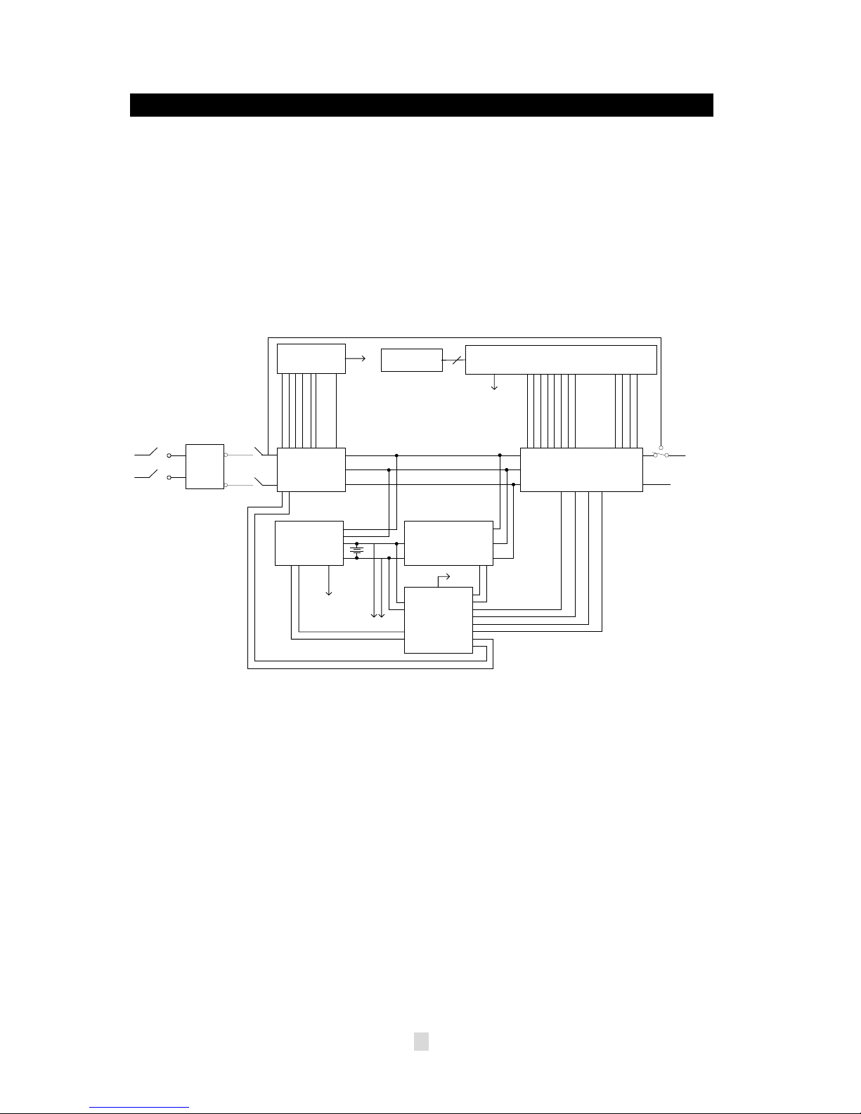
2-1 Theory of operation
The main topology of the UPS consists of bypass path, AC-DC converter,
DC-AC inverter, battery charger, DC-DC converter, control circuit and
detection circuit. Moreover, the intelligent power management software is
also optional. The function and efficiency are superior to the traditional UPS.
Description of block diagram
BYPASS
PFC Control
Circuit
LED Board
To Control Board
To Auxiliary Power
Control Board
EMI
Relay
AC-DC Double
Booster
Battery Bank
Charger DC-DC Converter
To Control Board
To External Battery Bank
Auxiliary
Power
Half-bridge DC-AC Inverter
To Control Board
Breaker
AC
I/P
Filter
Fig. 2.1 is the hardware block diagram of the UPS.
The UPS operation is described as below:
When the utility power is applied into the UPS, it was divided into two ways
after going through the breaker and EMI filter. One way is connected to
AC-DC converter which converts the utility AC power into a DC voltage which
is called DC-BUS voltage then divide into two path. One path goes to charger
which converts the DC-BUS voltage into a proper DC voltage to charge the
UPS battery. The other path goes into DC-AC half bridge inverter. The other
way works as a bypass path. The bypass relay near the output will choose
either the bypass path or inverter output. In general, the UPS will internally do
the self-diagnosis. If there is no problem, the bypass relay will choose the
inverter output. This is so called【ON-LINE mode】.
AC
BYPASS
RELAY
O/P
3
Page 6

In case the utility power fail, the AC-DC converter and charger will be off duty.
The DC-DC converter works and converts the battery voltage into DC-BUS
voltage. The DC-AC inverter converts the DC-BUS voltage into AC voltage.
This is so called
【ON-BATTERY mode】
.
The auxiliary power circuit supplies the designated power to all the control
circuits. Because the DC-AC inverter is always working, the DC-DC converter
can work rapidly and replace the AC-DC converter while the utility power fails.
Furthermore, the bypass relay continuously keeps in the position of inverter
output to supply the regulated power for the load. There is no power failure to
loading equipment.
2-2 Feature
The UPS, available in 1KVA, 2KVA and 3KVA, is an advanced on-line UPS
providing reliable and consistent sine-wave quality power to vital equipment.
It supports personal computers, networks, servers, telecommunication
equipment and a variety of other facilities. With its outstanding protection
features, the unit keeps your applications safe and running smoothly at all
times.
PFC (Power Factor Correction)
With this function, the investment in the capacity of circuit breakers can be
reduced, specially it will be highly regarded as an important feature in critical
load applications.
Complete Protection
On-line double conversion design, pure sine wave output and zero transfer
time provide best protection. With a built-in surge, spike and line noise
protection, the UPS prevents destructive hardware damage and extends
system life. The EMI/RFI filtering design prevents electrical noise from
affecting computer operation and data files. Besides, the UPS provides
built-in Fax/ Network cable (RJ11/RJ45) jacks protecting your hardware from
surge, spikes and line-noise that travel along communication lines, therefore
providing you a complete “back door” protection.
Intelligent design
Integrated with a microprocessor, the UPS is able to perform intelligent
functions. The UPS triggers over-voltage protection function and transfers to
On- Battery mode】even when utility voltage exceeds 280V for 220V Series.
【
In addition, the UPS can accept large voltage variation of 80V to 280V. Wide
4
Page 7
Input voltage range means less battery power usage frequency and longer
battery life-span. Besides, programmable outlet design, suitable for power
management, is also included in this unit.
Green function design
The UPS comes with an intelligent fan design, which can have variable fan
speed depending on load status, thereby saving the use of power and
reducing audible noise. Besides, the operation in sleeping mode is designed
to just keep charging which saves the energy a lot.
User friendly interface
The UPS provides a variety of functions which meet users’ needs. Users can
instantly understand the status of the UPS via the informative LED display.
Audible alarms, bar meters and status indicators, such as battery replace
indication, UPS fault, line condition, overload etc. are simple and easy for
user to understand. Moreover, users can simply reset the circuit breaker
instead of having to replace a fuse in the event of output overload.
Network Management
Build-in communication interface port supporting RS232 protocols enhances
the reliability and manageability of the UPS over all major operating systems,
including Windows 95/98, Windows NT, Netware, Unix, and others.
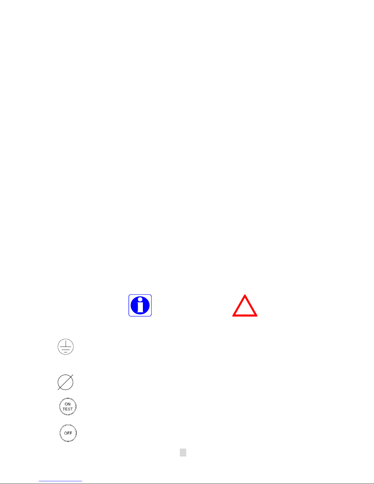
2-3 Annotation and symbol
The two signs shown on the manual indicating important instruction need to
be followed.
Read before Operation Maybe Dangerous/Follow Instructions
PROTECTIVE GROUNDING TERMINAL: A terminal which must be
connected to earth ground prior to making any other connection to the
equipment.
This symbol indicates the word “phase”.
This symbol indicates the principal on/off switch is in the “ON” position.
This symbol indicates the principal on/off switch is in the “STANDBY”
position.
!
5
Page 8
2-4 Front Panel
Fig 2-4 Front Panel for 1KVA & 2KVA & 3KVA
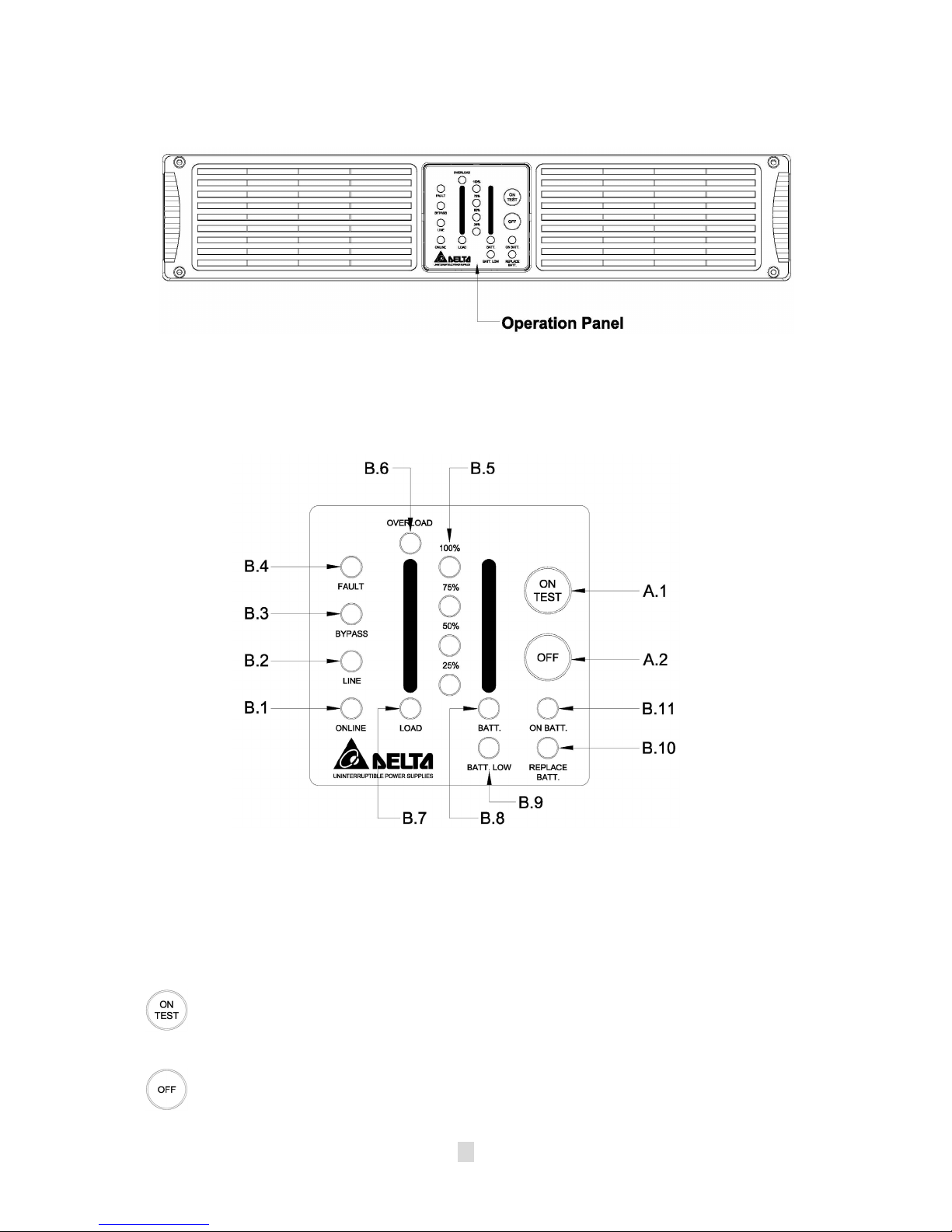
2-5 Operation Panel
Fig 2-5 Operation Panel
OPERATION PANEL
A. Button:
1. ON/TEST: The button is used for turning on the UPS, it also can
perform the test function in “ON-LINE mode”. In backup mode, this
button can turn off the buzzer for silence.
2. OFF: The button is used for turning off UPS.
6
Page 9

B. LED Display:
1. ON Line: The UPS is running in “ON-LINE mode”.
2. Line: The LED indicates the condition of UPS input line. If the input
voltage is too low, too high or out of frequency this LED will flash. When
line is blackout or ultra high voltage (>300Vac), this LED will light off.
3. Bypass: The LED indicates UPS in “BYPASS mode”.
4. Fault:
The LED indicates that the UPS is fault. The LED Flash indicates
that the UPS is overheat.
5. Level LEDs: The four LEDs indicate the battery capacity in
“ON-BATTERY mode” or UPS load percentage in “ON-LINE mode”.
6. Overload: The LED indicates UPS’ load exceed the rating, after a
limited period, the UPS will transfer to “
BYPASS mode
” and the LED
will still light on to alarm the user.
7. Load: “Level LEDs” shows the UPS load level when the LED lights up.
8. Battery:
lights up.
“Level LEDs” shows the current battery capacity when the LED
9. Battery low: The LED indicates the battery in battery low condition.
10. Battery replace: The LED indicates the batteries are weak and suggest
the user to replace the batteries.
11. ON Battery: The UPS is running in “ON-BATTERY mode” (backup
mode), the internal batteries supply power.
7
Page 10

2-6 Rear Panel
The rear panel is explained as follows: (Please refer to fig 2-6.1, 2-6.2)
Fig 2-6.1 (1KVA Rear Panel)
Fig 2-6.2 (2KVA &3KVA Rear Panel)
1. I/P BREAKER
2. INPUT SOCKET: AC input utility power supplies to the UPS via the
socket.
3. OUTPUT RECEPTACLES: The UPS supplies AC power to the load via
these receptacles.
4. SNMP SLOT:
UPS status via network.
5. External Batteries Connector: Used for connecting external battery
cabinets to extend back up time.
6. Fan: DC fans for cooling purpose.
7. TVSS (Transient Voltage Surge Suppressor) (RJ-45/RJ-11 SURGE
PROTECTOR): These connectors are used to prevent damage from
surge, noise and spike traveling form telephone or network line.
8. COMMUNICATION INTERFACE (RS-232):
used to communicate PC and UPS. Please refer to section 8 for more
information.
: This is used to prevent high input current from the UPS.
SNMP adapter can be inserted into this port for monitoring
The communication port is
8
Page 11

3. INSTALLATION
3-1 Unpacking
Please read this user manual before installing the UPS.
This UPS contains batteries which are potentially hazardous to
user, even when the UPS is not connected to the utility power.
Before unpacking the UPS, check the packing box. If there are
any visible damage, contact your dealer at once.
-This unit is to operate by any individuals with previous training.
-This unit should be installed by service personnel.
3-2 Before Installation
Avoid exposing the UPS to direct sunlight or other heat source.
The UPS should be facing away from direct sunlight glare.
Choose a well-ventilated area to position your UPS to allow
adequate dissipation of heat.
Ensure the UPS surrounding area is clean and free from
moisture.
Do not put heavy objects on the cable or power cord.
3-3 Installation
Notice:
- AC output need a disconnect device such as a breaker which has to be
provided by others.
- The wire length of output power cord connected to the output receptacle
or pressure terminal should be less then 10 meters.
- The UPS provide with pressure terminal connector for field installed wiring,
the terminal connector should be applied a 13.8 lb-in (1.554 N-m) of
tightening torque.
- The over current protection and short circuit protection for the AC output
is provided by internal circuits of UPS and breaker.
- Concerning about the battery voltage, ambient temperature and other
specifications of the UPS, please refer to the specification section of this
manual.
- Servicing of batteries should be performed or supervised by personnel
knowledgeable of batteries and the required precautions. Keep unauthorized
personnel away batteries.
- When replacing batteries, replace with the same type and number.
9
Page 12

1. Connecting to utility power
- Connect the IEC plug of power cord to the IEC 320 connector on the
UPS.
- Plug the other end of the power cord into a two-pole, three-wire,
grounding receptacle only. Avoid using extension cords and adapter plug.
- Turn on the input breaker (if the breaker can be turned on) on the rear
panel of UPS.
- After that, the fan (in rear panel) will run and all LEDs will light for about
2-3 sec. Meanwhile the CPU inside the UPS setups the initial parameters.
User also can check whether all LEDs are normal or not. The UPS is set
in “STANDBY mode” initially, after a ‘bee’ is heard, the load LED lights on
and the line LED shows AC utility status. Shown as fig 3-1.
Fig 3-1 Stand-By Mode
2. Charging the battery
- The battery charger of the UPS automatically charges the battery
whenever the power cord of UPS is connected to a acceptable utility
power.
- When UPS is running for the first time, charge the UPS for at least 6
hours to ensure batteries inside are fully charged before operation.
- You may immediately use the UPS without having to wait for the batteries
to be fully charged. However, it is advisable not to do this as UPS will
have a shorter back-up time than expected if such action is taken.
10
Page 13

3. Connecting the battery bank
- Utilize the battery connection cable packed with the battery bank.
- Connect on one end of the cable to the external battery connector of
UPS, and the other end to that of the battery bank.
- Warning: For safety reason, the manufacturer suggests that ONE UPS
CONNECTS AS MANY AS FIFTEEN EXTERNAL BATTERY BANKS.
- The battery banks should be installed by service personnel.
According to UL 1778 safety requirement: in order to remove the
※
battery power cord emergently, please plug in the power cord
directly.
According to EN50091-1-1 safety requirement: beside plugging in
※
the battery power cord, the battery power cord need to be fixed
with the screws.
Fig. 3-2 UPS Connected to External Battery Bank
11
Page 14

4. Connecting the load
- Calculate power consumption of your loads to ensure that the overload
condition will not happen.
- Plug the power cord of the equipment into the output receptacles on the rear
panel of the UPS.
- Turn on the equipment connected to the UPS.
- Caution: Do not connect a laser printer to the UPS.
!
- Caution: Do not connect the UPS to generator.
5. Connecting the RS-232
- Connect the interface signal cable between the RS-232 port on the rear
panel of UPS and COM1 or COM2 of computer if necessary.
- The D-sub 9 connector can work as a RS-232 communication port
depending on the type of cable and software used. Refer to section 8 for
more information.
Fig.3-3.1
UPS Connection for 1KVA:
(1) Connected to RS-232 cable
(2) Provides power to PC.
(3) Connected to utility power.
Fig 3-3.1
12
Page 15

Fig 3-3.2
UPS Connection for 2KVA or 3KVA:
(1) Connected to RS-232 cable
(2) Provides power to PC.
(3) Connected to utility power.
Fig 3-3.2
13
Page 16

4. OPERATION
4-1 Cold start when utility is not present
Even when there is no utility power, you can still turn on the UPS. Just press the
“ON TEST” button and hold for 2~4 second, the UPS will start up after you hear a
“bee”. The battery LED and on-battery LED will light on and the UPS runs on
“ON-BATTERY mode”. Shown as fig 4-1.
Fig 4-1 On Battery Mode
4-2 Turning “ON” the UPS
When the utility power is acceptable for the UPS, you can normally turn on the
UPS after pushing the “ON TEST” button and hold a few seconds until a “bee” is
heard. The bypass LED will extinguish after shortly light on. When the on-line
LED lights on, the UPS is running on “ON-LINE mode”. Shown as fig 4-2.
Fig 4-2 On-Line Mode
14
Page 17

4-3 Turning “OFF” the UPS
Push the “OFF” button for turning off the UPS, when a “bee” is heard release
your press. After a few seconds the UPS is off.
The UPS will keep charging when UPS is in “STANDBY mode” even though
the“OFF” button has been pressed. To fully turn off the UPS, it is advised to
unplug the power cord.
4-4 UPS self-test
If press the “ON TEST” button when the UPS is in “ON-LINE mode”, it will
make the UPS shift to【ON-BATTERY mode】and automatically perform a
self-test for about 10 seconds. (Shown as fig 4-3.) The self-test function will
check the condition of the battery. After self-test is finished and test is O.K,
the UPS will return to【ON- LINE mode】.
Fig 4-3 UPS Self-Test
4-5 Silence function
The buzzer can be turned “On” or “Off” by toggling the “ON TEST” button when
the UPS is in 【ON-BATTERY mode】.
4-6 Abnormal condition
If certain abnormal condition occurs, the UPS will send the following messages:
ON-BATTERY mode: When the UPS is in 【ON-BATTERY mode】, the on-
battery LED will light on, buzzer beep half second every 2 seconds and then the
UPS will start supplying power to load through batteries. Shown as fig 4-4.
15
Page 18

Fig 4-4 On-Battery Mode
OVERLOAD:
If the load exceeds the UPS rating, after a limited period, the
overload LED will light on and buzzer continuous beeping to alarm the user.
The user should unplug some uncritical loads to release the overload
condition. Shown as fig 4-5.
Fig 4-5 Overload and UPS turn into Bypass
BATTERY REPLACE:
This LED function is to alert user that the batteries
should be replaced. When the microprocessor in the UPS detects a battery
fault, the UPS alarm will give out three beeps. Each beep lasts for 0.5
seconds and interrupted by an interval of 0.5 seconds. After the initial 3 beeps,
the alarm will continue to sound every one hour. Shown as fig 4-6.
Fig 4-6 Battery Replace
16
Page 19

BATTERY LOW:
This function is to inform user the remaining power capacity
of the batteries. When batteries reach a low level condition, the UPS alarm
will beep half second every 1.5 seconds until running out of battery capacity.
Shown as fig 4-7.
Fig 4-7 Battery Low
SHORT CIRCUIT: When the output of the UPS shorts in【ON-LINE mode】or
ON-BATTERY mode】, the UPS will shut down (without output voltage). As
【
soon as the short circuit is happened, the fault LED will light on and the UPS
alarm will sound continuously. When remove short circuit, the UPS output will
recover. If short circuit is happened in “BYPASS mode”, the UPS will protect
itself by tripping the input breaker and shut down. Shown as fig 4-8.
Fig 4-8 Short Circuit
17
Page 20

4-7 UPS internal fault
If the following conditions occur, the UPS fails. At this time the UPS will
transfer to 【BYPASS mode】. The bypass LED and fault LED will light on
and alarm continuously. If utility is too low or too high the UPS output will be
disabled. For fault messages, please refer to the troubleshooting (section7)
of this manual.
- When the UPS inner component overheats, the UPS will protect itself by
thermo-switches. This status is so-called (“O.T.P”).
- When under (or over) voltage is happened in the UPS output. This kind of
fault will be detected by the microprocessor in the UPS and is so-called
“U.V.P” (“O.V.P”).
- When under (or over) bus voltage is happened in the UPS and is
so-called “
Bus U.V.P
” (“
Bus O.V.P
”).
4-9 Output U.V.P 4-10 Output O.V.P
4-11 DC BUS U.V.P 4-12 DC BUS O.V.P
4-8 Derating power
In the range of 80Vac to 175Vac, the UPS load capacity will decrease. This
function provides a wider operating power voltage range.
18
Page 21

5. MAINTENANCE
Normally, the life of battery is 3 years. But extreme operating condition and
environment may shorten its life-span.
To replace batteries, contact qualified personnel.
When UPS has been unused for a period of time, the batteries will discharge
slightly. It is recommended to charge the UPS once every 3 months.
Use a vacuum cleaner to get rid of any dust that may rest on the opening of
the fan.
Unplug the UPS when it is not used for a long time.
When cleaning the plastic case or front panel, only use a soft, dry cloth. If the
case or front panel is very dirty, use a neutral, non-abrasive detergent. Do not
use alcohol or ammonia based solutions.
When moving your UPS, always handle it with care.
Avoid spilling liquid on the UPS.
The equipment should be repaired and installed by individuals with previous
training.
When installing this equipment, it should be noted that the leakage current of the
UPS and its loads must not exceed 3.5mA in total for safety.
6. PLACEMENT
You can set the UPS on the Rack , You can make the UPS Erect by the Support
stands also.
To stably install the UPS of 1 & 2 & 3kVA models, you must set up UPS with
supporting stands.
The installation method is as shown below:
Fig 6-1 Erect the UPS with supporting stands
19
Page 22

7. TROUBLESHOOTING
2
Problem Possible Cause Solution
Press the “ON TEST” button to turn on the
ON/TEST button is not pushed.
UPS is not turned
on.
(No alarm, No LED
lights)
UPS does not
provide expected
back-up time.
All LEDs light on. Internal UPS fault.
“REPLACE
BATTERY” LED
lights on.
PC-UPS
communication does
not work properly.
UPS operates on
battery even though
the line is in normal
operating condition.
Battery low shut down and
utility is absent.
The rear panel input circuit
breaker is tripped. (Button is
tripped out)
UPS fault.
Batteries inside the UPS are
not fully charged.
UPS is overloaded. Remove some unnecessary loads.
Batteries are weak.
Charger fault or other reason. Call for service.
Weak batteries.
Incorrect transmission speed.
Incorrect RS-232 connection.
No incoming utility. Check input power connection.
The rear panel input circuit
breaker is tripped. (Button is
out).
Very high, low or distorted
utility voltage.
UPS.
(Refer section 4 to turn on the UPS.)
Waiting for line recovery.
1. Reduce some loads connected to the UPS.
2. Reset the circuit breaker. (Push
button in)
Call for qualified service personnel if above
actions do not solve the problem.
Recharge the batteries for at least 8 hours.
Batteries weak faster when used often or
operating at higher temperature.
If the battery is near the end of its life, call for
service personnel. Replace the battery even if
the REPLACE BATTERY LED does not light.
1. Turn off UPS.
2. Call for service.
1. Recharge the batteries for at least 8
hours.
. If problem remains Call for service
personnel to, replace the batteries.
Re-test after using another different
transmission speed.
Refer to communication interface (Section 8) of
this manual Re-connect the UPS with COM1 /
COM2 on PC again.
1. Reduce some loads connected to the UPS.
2. Reset the circuit breaker. (Push button in)
Have qualified electrician check the input
voltage.
Site wiring fault LED
(fault led flash).
UPS over
temperature.
“FAULT”LED lights
on, alarm beeps
“OVERLOAD” LED
lights on and buzzer
beeps continuously.
Wiring error such as reversed
hot/neutral.
The exhaust fans and ventilation
grills may be obstructed.
The environment temperature
exceeds 40
UPS failure. Call fore service engineer.
Overloaded. Remove some critical load.
o
C (104oF).
Get wiring checked by electrician.
Choose a well-ventilated area to position
your UPS to allow adequate dissipation of
heat.
Position your UPS in cooler area.
20
Page 23

8. COMMUNICATION INTERFACE
The UPS provides RS-232 protocols in one D-sub 9 connector. Using proper
UPS management software and cable, the UPS can be managed over
LAN/intranet/internet environment.
UPS can be also managed through IE / network management software when
it’s installed an external SNMP card .The detail install method reference to
the“SNMP card user’s manual”
The pin assignment of the D-sub 9 connector is defined as follows:
PIN
ASSIGNMENT DESCRIPTION
RS232
1 GND 5
2 UPS TxD(typical RS-232 level) 6
3 UPS RxD(typical RS-232 level) PNP 7
4 8
9
8-1 RS-232
Pin 2 : PC receives line
RS-232
Pin 3 : PC transmits line RS-232 data to UPS.
Pin 5 : Signal ground.
Pin 7 : Reversed for plug and play function.
The
RS-232
communication port provides the following functions:
1) Monitoring charger status
2) Monitoring battery status and condition
3) Monitoring inverter status
4) Monitoring UPS status
5) Monitoring the utility status
6) Providing the power switch function for computer to turn on/off the utility
on schedule for power saving
7) Adjustable Transfer voltage
data from UPS.
6789
2345
1
Fig 8-1 Pin Assignment
PIN
The UPS data is provided at 2400 bps baud rate and made up of 8-bit, 1
stop-bit and no parity bit. All information is encoded in ASCII format.
HARDWARE:
- BAUD RATE--------------2400 bps - DATA LENGTH----------8 bits
- PARITY--------------------NONE - STOP BIT-----------------1 bit
CABLING:Standard D-sub 9 cable (UPS side: male, PC side: female)
21
Page 24

9. Technical specifications
Model
Capacity
Rated Voltage 230V
Input
Output
Outlet Receptacle
Battery
Transfer Time Transfer Time 4 ms
LED
Interface
Standards EMC Approval EN50091-2 CLASS A
Environment
Others
Appearance
Voltage Range
Frequency
Power Factor
Voltage 230V
Frequency 50Hz
Voltage Regulation
Frequency Accuracy
Wave Form Pure Sine Wave
Transient Response
THD
Overload Capacity
Crest Factor 3:1
Efficiency (AC-AC)
Battery Voltage 36 V 72V 72V
Battery Type (Lead acid) 12V/ 7Ah 12V/ 9Ah
Back-up Time (Typical) 5mins (700W) 5mins (1400W)
Recharge Time
LED Status
Alarm Buzzer
DB9 RS232
SNMP Slot Internal Internal
Noise (At 1 Meter) 46dBA 47dBA 55 dBA
Operating Temperature
Humidity 0%~90% (Non-Condensing)
Battery Start Yes
Extendable Battery Bank Yes
Long Time Model Yes (Optional)
Dimension (W×D×H)
Weight Long Time 6.7 kg / 14.7 lb 9.2 kg / 20.2 lb
GES102R GES202R GES302R
1KVA/700W 2KVA/1400W 3KVA/2100W
175V∼280V(Full Load);
80V~175V(100% to 50% Load de-rating Linearly)
50Hz (±5.0 Hz)
≥0.97
±2%
±0.05 Hz
8% (10%∼90% Linear Load)
+
≤3%(Linear Load); ≤6%(Computer Load)
105%-125% for 3mins; 125%-150% for 30secs; >150%
for 1sec
≥ 87%
IEC320×1×4 IEC320×2×4 + IEC320×1
8 Hours After Complete
Discharge to Recover
80%
On-line、Bypass、On-battery、Overload、Battery Low、
Fault、Battery Replace、Battery Level、Load Level
0-40℃
440x455x88.5 / mm
17.3 x 17.9 x 3.48/inch
5mins
(2100W)
8 Hours After Complete
Discharge to Recover 90%
440 x 455 x 88.5 / mm
17.3 x 17.9 x 3.48 / inch
* All specifications are subject to change without prior notice.
22
Page 25

 Loading...