

Page 1
®
Made
in
Germany
NMT SMART
NMTC MODÜL
GB
D
TR
7340092 v.1
INSTALLATION AND OPERATING MANUAL
MONTAGE- UND BETRIEBSANLEITUNG
MONTAJ VE KULLANIM KILAVUZU
Page 2
Compliance of
the product with
EU standards
EU directive Harmonized standard
Machinery 2006/42/EC EN 809
Low Voltage 2006/95/EC
Electromagnetic compatibility
(EMC) 2004/108/EC
Ecodesign Directive
(2009/125/EC)
EN 61000-3-2; EN 61000-3-3
EN 60335-1
EN 60335-2-51
EN 55014-1; EN 55014-2
EN 16297-1:2012
Circulators:
Commission Regulation No.
641/2009.
Pump type EEI
NMT(D) SMART (C) xx/120-xxx EEI≤0,21 – Part 2
NMT(D) SMART (C) xx/100-xxx EEI≤0,21 – Part 2
NMT(D) SMART (C) xx/80-xxx EEI≤0,21 – Part 2
NMT(D) SMART (C) xx/60-xxx EEI≤0,21 – Part 2
NMT(D) SMART (C) xx/40-xxx EEI≤0,21 – Part 2
and
EN 16297-2:2012
Page 3

INHALTSVERZEICHNIS
1. Allgemeine Beschreibung 4
2. Fördermedien 4
3. Installation 4
4. Stromanschluss der Pumpe 5
5. Einrichtung und Inbetriebnahme 6
5.1. Funktionselemente am Bedienfeld 6
5.2. Inbetriebnahme 6
5.3. Funktionstasten 6
5.4. Einstellen der Betriebsarten 7
5.5. Beschreibung der Betriebsarten 8
5.6. Rücksetzen der Pumpe auf Werkseinstellung 9
5.7. Doppelpumpe NMTD SMART (C) 9
6. Technische Daten 10
7. Fehlermeldung und Abhilfe 11
NMTC modul
INHALTSVERZEICHNIS
1. Allgemein 12
2. Inbetriebnahme 12
3. Elektrischer Anschluss 12
4. Technische Daten 13
D
-3-
Page 4

1. Allgemeine Beschreibung
Die Umwälzpumpe NMT SMART ist für die Umwälzung von Wasser in
D
Heizungsanlagen und Trinkwarmwasseranlagen bestimmt. Sie unterscheiden
sich von den bestehenden Standardumwälzpumpen darin, dass sie sich
durch Regelung „Proportionaldruckregelung“ oder „Konstantdruckregelung“
der Anlage kontinuierlich anpassen und dadurch eine optimale Einstellung
des Betriebspunktes erreichen.
2. Fördermedien
Reine, dünnüssige Medien, die für Zentralheizungsanlage geeignet sind.
Das Wasser soll den gängigen Normen entsprechen, wie z.B.: VDI 2035.
Das Medium darf keine aggressiven oder explosiven Additive enthalten,
keine Beimengen von mineralischen Ölen oder faserigen Partikel. Die
Pumpe darf nicht zur Förderung von entammbaren und explosiven Medien
benutzt werden.
Zugelassene
Raumtemp. [°C]
0 bis 25 2 110
30 2 100
35 2 90
40 2 80
Medientemperatur
min. [°C] max. [°C]
Der Betrieb der Pumpe außerhalb der angebenen Raum- und
Mediumtemperaturen kann die Lebensdauer der Pumpe beeinträchtigen
und die Gewährleistung aufheben.
3. Installation
Die Umwälzpumpe muss so installiert werden, dass sich die Achse des
Elektromotors in horizontaler Position bendet (siehe Bild 3.1). Zugelassene
und unzulässige Positionen sind auf Bild 3.2 aufgezeigt. Der Pfeil auf der
Hydraulik zeigt die Richtung des Durchussmediums an.
Falls nicht genug Platz für den Stromanschluss vorhanden ist, kann der
Elektromotor in die horizontale Position gedreht werden. Die vertikale
Position ist nicht erlaubt (siehe Bild 3.3c). Vor der Versetzung muss das Vor-
und Rücklaufventil geschlossen werden, sowie die Schrauben gelöst (Bild
-4-
Page 5

3.3). Der Elektromotor wird gedreht, wie auf Bild 3.3a und 3.3b aufgezeigt.
Vor Inbetriebnahme der Pumpe ist die Heizungsanlage mit Heizungswasser
zu befüllen und zu entlüften. Für den einwandfreien Betrieb muss am
Saugstutzen der Mindest-Zulaufdruck gegeben sein.
Die Umwälzpumpe ist selbstentlüftend und muss daher vor Inbetriebnahme
nicht entlüftet werden. Luft in der Pumpe kann Geräusche verursachen,
jedoch entweicht nach kurzer Zeit diese selbständig und eventuelle
Geräusche verschwinden.
ACHTUNG !
• Der maximale Druck im System beträgt 1 MPa (10 bar).
• Die Pumpe muss mit Fördermedium gefüllt sein und darf niemals trocken
laufen.
• Die Öffnungen zum Ablauf des Kondenswassers (siehe Bild 3.1 Detail A),
den Elektromotor sowie den Klemmkasten niemals abdämmen.
• Während des Betriebes der Pumpe erwärmt sich diese und darf daher
nicht berührt werden.
• Der zugelassene Arbeitsbereich der Pumpe wird im Diagramm in dieser
Anleitung dargestellt.
4. Stromanschluss der Pumpe
Der elektrische Anschluss der Pumpe darf nur von qualiziertem Fachpersonal
durchgeführt werden.
Der Anschluss an das Stromnetz erfolgt mit Hilfe des mitgelieferten Steckers,
Anschluss an das Kabel siehe Beipackzettel.
Der Elektroanschluss der Pumpe an das Stromnetz (1~230V, 50Hz) muss mit
einem entsprechenden Netzkabel ausgeführt werden (3G 1 mm ², H05RR-F
Anschlusskabel).
D
Der elektrische Anschluss und die erforderlichen Schutzmaßnahmen sind in
Übereinstimmung mit den örtlichen Vorschriften vorzunehmen.
-5-
Page 6
5. Einrichtung und Inbetriebnahme
D
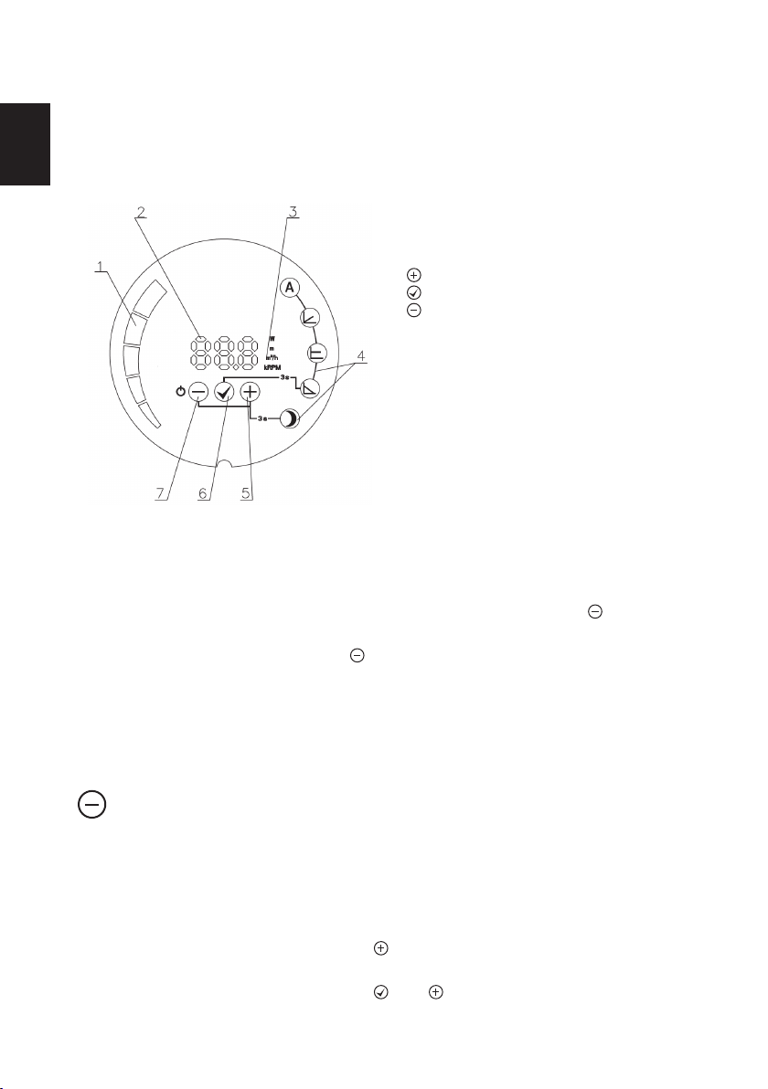
5.1. Funktionselemente am Bedienfeld
1 Leuchtfelder zur Wertanzeige
2 Numerische Wertanzeige
3 Anzeige der ausgewählten Parameter
4 Anzeige der Betriebsart
5 Taste
6 Taste
7 Taste
5.2. Inbetriebnahme
Bei erster Inbetriebnahme arbeitet die Pumpe nach Werkseinstellung im
Automatikbetrieb.
Zum Ausschalten der Pumpe drücken Sie 5 Sekunden die
ausgeschalteten Zustand zeigt die Anzeige OFF an.
Zum Einschalten drücken Sie die Taste.
Die Pumpe merkt sich die letzte Sollwerteinstellung und läuft bei
Wiederinbetriebnahme in dieser an.
Taste. Im
5.3. Funktionstasten
Taste
Kurz halten:
• Umstellen der Parameter abwärts, Parameterwerte werden nicht verändert
• Umstellen der Betriebsart abwärts, bei Auswahl der Betriebsart
• Umstellen der Parameterwerte abwärts, bei Auswahl der Parameterwerte
Lang halten:
• 3 Sekunden gemeinsam mit der
Taste für Nachtabsenkung
• 5 Sekunden um die Pumpe abzuschalten
• 5 Sekunden gemeinsam mit der und Taste für Werkseinstellung
-6-
Page 7

Taste
Kurz halten:
• Um die ausgewählten Werte der Betriebsart und der Parameter zu
bestätigen
Lang halten:
• 3 Sekunden um den Wechsel zwischen den Betriebsarten einzuleiten
• 5 Sekunden gemeinsam mit der und Taste für die Werkseinstellungen
der Pumpe
Taste
Kurz halten:
• Umstellen der Parameter aufwärts, wenn Parameterwerte nicht verändert
werden
• Umstellen der Betriebsart aufwärts, für die Auswahl der Betriebsart
• Umstellen der Parameterwerte aufwärts, für die Auswahl der
Parameterwerte
Lang halten:
• 3 Sekunden gemeinsam mit der Taste für Nachtabsenkung
• 5 Sekunden gemeinsam mit der und Taste für die Werkseinstellung
5.4. Einstellen der Betriebsarten
Für den Wechsel zwischen den Betriebsarten drücken Sie die
Sekunden und wählen danach die gewünschte Betriebsart mit der oder
Taste aus. Die Auswahl wird mit der Taste bestätigt.
Nach Bestätigung der Betriebsart wird automatisch die Auswahl der
Parameter angezeigt (auβer im Automodus). Man kann diese in Bezug auf
die ausgewählte Betriebsart einstellen (siehe individuelle Betriebsart).
Mit der und Taste stellen Sie die Parameterwerte ein und bestätigen mit
der Taste.
Zum Ein- und Ausschalten der Nachtabsenkung halten Sie die Taste und
Taste gemeinsam 3 Sekunden gedrückt.
Innerhalb der Betriebsarten können die Parameterwerte mit der und
Taste überprüft werden.
Durch Drücken der Taste und mit Hilfe der und Taste werden diese
verändert und mit der Taste bestätigt.
Taste 3
D
-7-
Page 8
5.5. Beschreibung der Betriebsarten
-
Max.
H
Q
Hset
2
Proportionaler Druck
+
H
set
-
Max.
H
Q
Hset
2
Proportionaler Druck
+
H
set
Max.
+
H
Q
H
set
-
Die Umwälzpumpe arbeitet in 4 verschiedenen Betriebsarten in denen
D
die Pumpenleistung optimal an die aktuelle Anlagenbedingung angepasst
werden kann.
Betriebsarten:
• Automatik (Werkseinstellung)
• Proportionaler Druck
• Konstanter Druck
• Konstante Umdrehungen
Jede dieser Betriebsarten kann mit der Betriebsart Nachtabsenkung
kombiniert werden.
A
Automatik (Werkseinstellung)
Im Automatik Modus passt sich die Pumpenleistung automatisch dem Druck
der Heizanlage an und bestimmt den optimal Betriebspunkt.
Diese Betriebsart wird in den meisten Fällen empfohlen.
In dieser Betriebsart können die Parameter nur überprüft werden, nicht verändert.
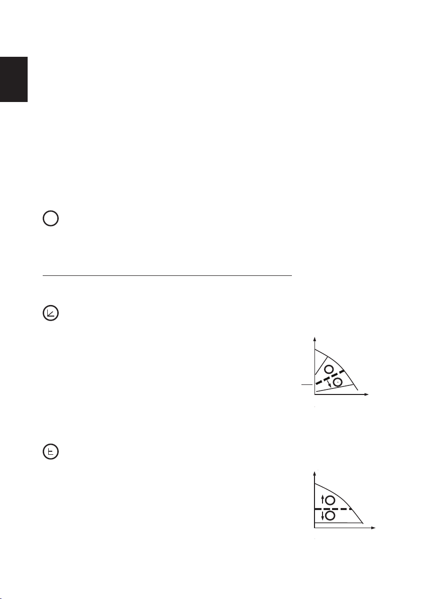
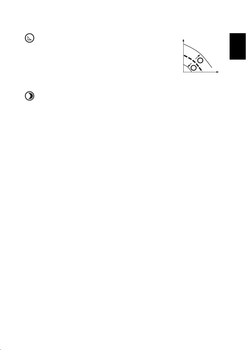
Proportionaler Druck
In dieser Betriebsart wird der Differenzdruck in
Abhängigkeit vom Förderstrom geregelt. Der Druck
entspricht dem eingestelltem Druck (Hset) bei maximaler
Kraft, bei 0 Durchuss entspricht dieser 50% des
eingestellten Druckes. Dazwischen verändert sich der
Druck linear in Abhängigkeit zum Durchuss.
Bei regulierbarer Betriebsart wird nur der Druck (Hset)
eingestellt, alle anderen Parameter können nur kontrolliert werden.
Konstanter Druck
Die Pumpe behält den eingestellten Druck bei (Hset) von
0 bis zur maximalen Stärke, danach beginnt der Druck
zu fallen.
Bei konstantem Druck kann nur der Druck, den die
Pumpe halten soll, eingestellt werden.
Die anderen Parameter können nur kontrolliert werden.
-8-
Page 9
Konstante Umdrehungen
-
Max.
H
Q
Hset
2
Proportionaler Druck
+
H
set
Max.
+
H
Q
H
set
-
Min.
H
Q
Konstante Umdrehunge n
RPM
set
Max.
+
-
Die Pumpe arbeitet unter den eingestellten Umdrehungen
(RPMset).
In dieser Betriebsart können nur die Umdrehungen
eingestellt werden, die anderen Parameter können nur
kontrolliert werden.
Nachtabsenkung
Im Betriebszustand Nachtabsenkung (Anzeige am Bedienfeld leuchtet)
wechselt die Pumpe automatisch, abhängig von der Medientemperatur,
zwischen der eingestellten Betriebsart und der Nachtabsenkung.
Bei einem Temperaturabfall des Mediums von 15-20°C (innerhalb ca. 2
Stunden), beginnt die Anzeige Nachtabsenkung zu blinken und die Pumpe
wechselt auf Nachtbetrieb. Bei Temperaturanstieg des Mediums leuchtet die
Anzeige und die Pumpe wechselt in die zuvor gewählte Betriebsart zurück.
Die Nachtabsenkung arbeitet nur in Verbindung mit einer der oben
aufgeführten Betriebsarten.
5.6. Rücksetzen der Pumpe auf Werkseinstellung
Zum Rücksetzen der Pumpe auf die Werkseinstellung halten Sie alle Tasten
gleichzeitig 5 Sekunden gedrückt. Die Pumpe wechselt in den Automodus,
alle vorherigen Sollwerteinstellungen sind gelöscht.
D
5.7. NMTD SMART (C)
Doppelpumpen bestehen aus zwei Pumpenköpfen, die in einem Gehäuse
hydraulisch parallel angeordnet sind. Eine eingebaute förderstromgesteuerte
Umschaltklappe verhindert den Rückströmen durch die stehende Pumpe.
Jeder Pumpenkopf wird separat an den Stromkreis angeschlossen.
Die NMTD SMART C Serie ermöglich mit Hilfe des Kommunikationsmodules
(C) die Kommunikation der einzelnen Pumpenköpfe miteinander, dies ist bei
der NMTD SMART Serie ohne Kommunikationsmodul nicht möglich.
Die Funktion “Nachtabsenkung” ist bei Doppelpumpen nicht empfehlenswert!
Zudem bietet die NMTD SMART C Pumpe folgende Betriebsarten:
· Wechselbetrieb (Werkseinstellung) – die Pumpenköpfe arbeiten im
· Reservebetrieb - Ein Pumpenkopf übernimmt permanent die Funktion, der
Wechselbetrieb. Während ein Pumpenkopf fördert, steht der andere still.
Alle 24 Stunden, oder im Falle einer Störung, ndet ein Wechsel statt
andere Pumpenkopf steht auf Reservebetrieb. Bei einer Fehlermeldung
übernimmt die Reservepumpe die Funktion.
-9-
Page 10

Durch Drücken der Taste für 5 Sekunden auf der ruhenden Pumpe wird
diese ausgeschaltet und der Reservebetrieb aktiviert
D
· Parallelbetrieb - Beide Pumpen arbeiten gleichzeitig.
Förderhöhe bzw. Drehzahl der einzelnen Pumpenköpfe wird bei beiden auf
identische Parameter eingestellt und aktiviert somit diese Arbeitsweise.
Wenn ein einzelner Pumpenkopf die erforderliche Pumpenleistung nicht
erreichen kann, wird der zweite Pumpenkopf zur Unterstützung aktiviert.
NMTD SMART
Folgende Betriebsarten sind möglich, für das Ein- und Ausschalten sorgt der
Betreiber:
· Wechselbetrieb – die Pumpenköpfe arbeiten im Wechselbetrieb. Während
ein Pumpenkopf fördert, steht der andere still. Im Falle einer Störung
muss die Reservepumpe in Betrieb genommen werden. Wir empfehlen
eine monatliche Inbetriebnahme der Reservepumpe.
· Parallelbetrieb - Beide Pumpen arbeiten gleichzeitig, unabhängig
voneinander.
Förderhöhe bzw. Drehzahl der einzelnen Pumpenköpfe wird bei beiden auf
identische Parameter eingestellt.
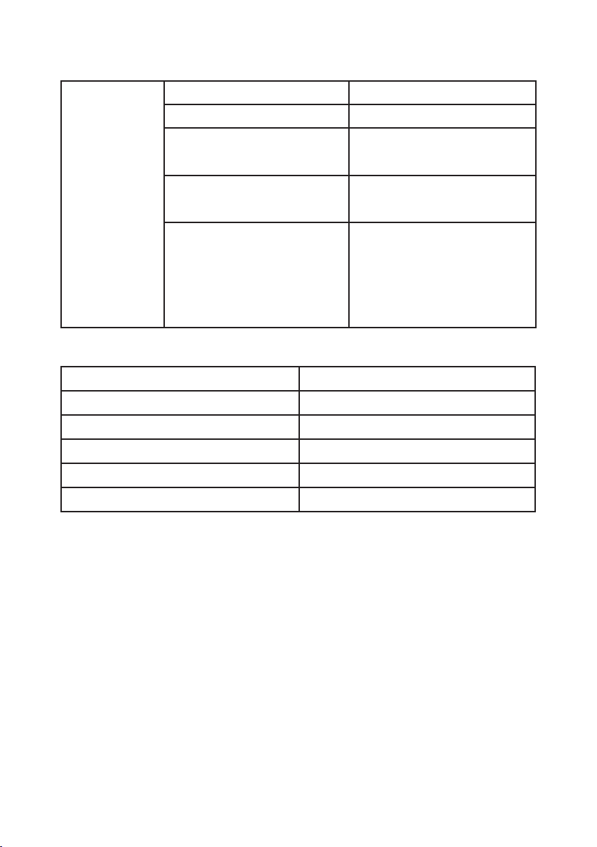
6. Technische Daten
NMT(D) SMART (C)
Pumpentyp xx/120-xxx xx/100-xxx xx/80-xxx xx/60-xxx xx/40-xxx
Stärke P
Bemessungsstrom In 0,1-1,55A 0,1-1,5A 0,1-1,15A 0,1-0,75A 0,1-0,5A
Stromversorgung 1~230V, 50Hz
Motorschutz externer Schutz ist nicht notwendig
Schutzklasse IP44
Isolierungsklasse F
Relative Feuchtigkeit max. 95%
Raumtemperatur 0-40°C
Medientemperatur 2-110°C
Systemdruck bis zu 1 MPa (10 bar)
1
10-180W 10-180W 10-140W 10-90W 10-60W
-10-
Page 11

7. Fehlermeldung und Abhilfe
E X Y
Bei Fehlermeldung zeigt die Pumpe folgende Meldung an:
Fehlergruppe Service code
Fehlergruppe
Fehler-gruppe (X) Fehlerbeschreibung Mögliche Ursache und Abhilfe
D
1 Trockenlauf
2 Motorüberlastung
3 Motorüberhitzung
4 Elektronikfehler
5 Defekt am Motor/Stator
Fördermedium fehlt,
überprüfen sie den Inhalt der
Heizanlage
Überhöhte Stromspannung
oder blockierter Rotor.
Überprüfen Sie den Rotor bei
wiederholter Fehlermeldung
Zu hohe Motortemperatur
erreicht, automatisch präventiv
abgeschaltet. Nach Abkühlung
startet die Pumpe automatisch.
Elektronikfehler, Pumpe läuft
zwar aber Servicetechniker
kontaktieren.
Motorstörung, Servicetechniker
kontaktieren.
Der Servicecode dient dem Servicetechniker und dem Werksdienst
Falls die Pumpe nicht reagiert, vom Stromnetz trennen und erneut
anschliessen.
-11-
Page 12

NMTC modul
D
1. Allgemein
Die Betriebsanleitung beinhaltet nur allgemeine Hinweise zur Inbetrieb-
nahme und Sicherheit. Weiter Informationen und Details ndenSie auf
unserer Internetseite unter:
http://www.deltaenerjisistemleri.com.tr
2. Inbetriebnahme
Das NMTC Modul ist ein optionales Kommunikationsmodul, das nachträglich
auf die Pumpe installiert werden kann oder bereits in der Pumpe integriert
ausgeliefert wird.
NMTC Modul Funktionen:
– Ethernet Verbindung
– Modbus RTU Verbindung
– 0-10V Steuerungsausgang
– 3 digitale Eingänge
– 1 Relaisausgang
3. Elektrischer Anschluss
Der elektrische Anschluss der Pumpe an das Stromnetz muss nach den
Weisungen und Vorschriften lokaler Energieunternehmen durchgeführt
werden.
BEACHTEN!
• Vor Inbetriebnahme bzw. Montage des Modules Stromzufuhr
unterbrechen
• Kabelanschluss des Modules seitlich legen, Überkreuzungen über der
Modemplatine vermeiden.
• Die Relaisanschlüsse (NO, C, NC) müssen getrennt von den übrigen
Anschlüssen isoliert werden, nicht mehr als 15 mm abisoliert.
-12-
Page 13

4. Technische Daten
Temperatur Umfeld: 0 °C bis 40 °C.
Luftfeuchtigkeit Umfeld: <95 % relative Luftfeuchtigkeit
D
Wir behalten uns das Recht vor, technische Änderungen vorzunehmen!
-13-
Page 14

Content
1. Use 15
2. Medium types 15
3. Installation 15
4. Electrical connection 16
GB
5. Setup and operation 17
5.1. Control panel 17
5.2. Switching the pump on and off 17
5.3. Pump functions 17
5.4. Operation and setting of pump modes 18
5.5. Mode descriptions 19
5.6. Setting the pump to the factory settings 20
5.7. Twin-head pumps NMTD SMART (C) 20
6. Technical specications 21
7. Overview of possible errors and solutions 22
NMTC module
Content
1. General 23
2. Applications 23
3. Electrical installation 23
4. Technical data 24
-14-
Page 15

1. Use
The NMT SMART pumps are intended for forced circulation of the medium in
central heating systems. The pump constantly measures pressure and ow,
and adapts the speed to the selected pressure.
2. Medium types
A medium that is pure water or a mixture of pure water and antifreeze, which
is appropriate for a central heating system, must be provided. The water
must meet water quality standards, such as: VDI 2035. The medium must
be free from aggressive or explosive additives, free from mixtures of mineral
oils and solid or brous particles. The pump should not be used for pumping
ammable, explosive media, and in an explosive atmosphere.
Permitted ambient and media temperature:
GB
Ambient
temperature [°C]
0 to 25 2 110
30 2 100
35 2 90
40 2 80
Media temperature
min. [°C] max. [°C]
Operation outside recommended conditions may shorten pump lifetime and
void the warranty.
3. Installation
The pump must be mounted so that the electric motor axis is in a horizontal position
(see Figure 3.1). The permitted and prohibited positions are shown in Figure 3.2.
The arrow on the hydraulic part indicates the direction of the medium ow.
If there is not enough space for an electrical connection, the electric motor
part can be rotated so that the electrical connector is in a horizontal position.
A position with the electrical connector vertically above the motor is not
permitted (see Figure 3.3c). Before we must close the block valve on the
pressure and suction side of the pump and unscrew the screws (Figure 3.3).
We can turn the electric motor part as shown in Figures 3.3a or 3.3b.
Before starting the pump, the pump must be lled with the medium, and the
-15-
Page 16

air completely bled out of the system. For proper operation, pressure must
be maintained on the suction side of the pump. The pump does not have
screws for bleeding the air, as it is automatically bled with the system. The
air in the pump generates noise. This disappears after a short time and the
pump operates normally.
GB
WARNING!
• The maximum pressure in the system is 1 MPa (10 bar).
• The pump must always be lled with the pumped medium!
• The pump’s openings and electric motor housing (Figure 3.1, detail A)
between the hydraulic housing and the electric motor housing should
not be insulated, since the thermal insulation might prevent cooling and
condensate drain from the pump’s motor housing.
• During operation, the pump heats up, or is heated by the pumped medium,
and should not be touched – risk of burns. The permitted working area of
the pump is dened by the diagram in these instructions.
4. Electrical connection
Connection of the pump must be carried out by qualied personnel.
Connection to the power supply is carried out with the enclosed connector,
the mounting of which is shown in the picture accompanying the connector.
The electric connection of the pump to the network (1~230V, 50Hz) must be
done with the appropriate power cord (equivalent to a 3G 1 mm ², H05RR-F
connection cable). When connecting the pump, the following must be
considered:
• the device for separating all the phases from the power supply must
be installed in the electric installation in accordance with the national
installation regulations,
• connection of the connecting cable must be done in a manner that
ensures it is never in contact with the casing of the device, due to the
high temperatures of the casing,
• the device should not be used by persons (including children) with
reduced physical, sensory or mental abilities, or with lack of experience
or knowledge, unless they are supervised or instructed on the use by a
person responsible for their safety,
• children should always be supervised to prevent playing with the device.
-16-
Page 17

5. Setup and operation
5.1. Control panel
1 Bar display of values
2 Numerical display of values
3 Unit display of the currently selected
parameter
4 Display of the currently selected mode
5 key
6 key
key
7
5.2. Switching the pump on and off
When the pump is connected to the network for the rst time, it operates with
the factory settings in automatic mode.
With subsequent start-ups, the pump will operate with the last settings that
were set prior to its shut-down.
To switch the pump off, press and hold the
key for 5 seconds, until OFF is
shown on the display. When the pump is switched off, the numerical display
shows OFF.
To turn the pump on, press the key briey.
GB
5.3. Pump functions
Key
Short press:
• Scrolling through parameters downwards when not changing parameter values,
• Scrolling through modes downwards when mode selection is selected,
• Changing parameters downwards when setting parameter values.
Long press:
• 3 seconds together with key to select night mode,
• 5 seconds to switch off the pump,
• 5 seconds together with and keys to restore pump to factory settings.
-17-
Page 18

Key
Short press:
• To conrm currently selected values of both mode and parameter.
Long press:
• 3 seconds to trigger mode selection,
• 5 seconds together with long press on and keys to restore pump to
GB
factory settings.
Key
Short press:
• Scrolling through parameters upwards when not changing parameter
values,
• Scrolling through modes upwards when mode selection is selected,
• Changing parameters downwards when setting parameter values.
Long press:
• 3 seconds together with key to select night mode,
• 5 seconds together with and keys to restore pump to factory
settings.
5.4. Operation and setting of pump modes
For transition between modes (except for night mode), we hold the
3 seconds and then select the mode in which we wish the pump to operate
with or keys. We conrm the selection with the key.
After conrming the mode, the parameter, that can be set in this mode will
automatically be chosen and displayed (except for auto mode). If necessary,
we set the parameter value with and keys, and then conrm the setting
with the key or just press the key.
To turn on and turn off the night mode, we simultaneously press and
keys and hold them for 3 seconds.
We can scroll through the parameter values within a mode with and
keys. We select the parameter that can be adjusted (see individual mode) in
the mode with the key and set the desired value with and keys. We
conrm the selected value with the key.
key for
-18-
Page 19

5.5. Mode descriptions
-
Max.
H
Q
Hset
2
Proportional pressure
+
H
set
-
Max.
H
Q
Hset
2
Proportional pressure
+
H
set
+
H
Q
H
set
Constant pressure
-
Max.
The pump can operate in 4 different modes. We can set the pump in the most
appropriate mode, depending on the system where the pump operates.
The pump modes:
• Automatic mode (factory settings)
• Proportional pressure
• Constant pressure
• Constant speed
Each mode can be combined together with night mode.
A
Automatic mode (factory setting)
In automatic mode the pump automatically sets the operating pressure,
depending on the hydraulic system. By doing so, the pump nds the optimal
operating position.
This mode is recommended in most systems.
The parameters cannot be set; they can only be scrolled through.
Proportional pressure
The pump maintains the pressure with relation to the
current ow. The pressure is equal to the set pressure
(Hset on the drawing) at maximum power; at 0 ow it is
equal to 50% of the set pressure. In between, the
pressure changes linearly, relative to the ow.
In regulated mode we can only set the pump pressure
(Hset on the drawing). We can only scroll through the
other parameters.
GB
The pump maintains the currently set pressure (Hset on
the drawing), from 0 ow to maximum power, where the
pressure begins to drop.
At constant pressure, we can only set the pressure (Hset
on the drawing) which the pump will maintain. We can
only scroll through the other parameters.
Constant pressure
-19-
Page 20

Constant speed
-
Max.
H
Q
Hset
2
Proportional pressure
+
H
set
+
H
Q
H
set
Constant pressure
-
Max.
Min.
H
Q
Constant revolutions
RPM
set
Max.
+
-
The pump operates with the currently set speed
(RPMset on the drawing).
In the unregulated mode, we can only set the speed
at which the pump will operate. We can only scroll
GB
through the other parameters.
Night mode
When the pump operates in night mode, it automatically switches between
the selected operating curve in the mode and night curve. The transition to
the night mode depends on the media temperature in the system.
When the night mode is prepared for operating, its icon illuminates and the
pump operates in the selected operating curve of the mode. When the pump
identies the media temperature fall by 15-20C° (approximately during 2
hours), the icon starts to blink and the pump switches to the night curve.
When the media temperature rises again, the icon stops blinking and the
pump passes over to the operating curve in the selected operating mode.
The night mode operates only in combination with the above indicated
modes. It is not an independent operating mode.
5.6. Setting the pump to the factory settings
To restore factory settings to the pump, it is necessary to press and hold all
three keys for 5 seconds. The pump is set to the automatic mode of operation.
The previously set values for pressure and revolutions will be deleted.
5.7. Twin-head pumps NMTD SMART (C)
Pumps have a common hydraulic housing that is equipped with a change-
over ap and two pump heads, separately connected to the electrical grid.
Pumps that communicate with each other. – NMTD SMART C
Pumps without an communication option – NMTD SMART
With this use, we recommend that night mode isn't used.
-20-
Page 21

NMTD SMART C
In this mode both pumps can work in different modes, switching between
pumps is made by NMTC module.
- Alternating mode [factory set] - One pump works, while the other one is
in standby. Pumps automatically switch on and in to standby every 24
hours, or when an error occurs on one pump.
- Reserve mode - One pump is always on, while the other one is in standby.
If an error occurs, then the reserve pump will turn on. This mode is turned
on, so that you put the pump that you want to be in standby, to standby by
holding key for 5 seconds.
- Combined mode – both pumps work with the same head in constant
pressure mode. This mode is used when there is a need for a ow that a
single pump can't reach. When the limit of the rst pump is reached, then
the other one will turn on supply the needed power to reach that ow.
This mode is activated, so that you set the same constant pressure head
on both pumps.
NMTD SMART
In this mode the pumps can work in different modes. The user takes care of
switching on and off of the pumps.
- Reserve mode - One pump works, while the other one is in standby. It is
recommended that the reserve pump is turned on at least once a month.
- Combined mode – Both pumps work, regardless of each other. Pumps
need to be set at the same constant speed.
GB
6. Technicalspecications
NMT(D) SMART (C)
Pump type xx/120-xxx xx/100-xxx xx/80-xxx xx/60-xxx xx/40-xxx
Power P
Rated current In 0,1-1,55A 0,1-1,5A 0,1-1,15A 0,1-0,75A 0,1-0,5A
Power supply 1~230V, 50Hz
Motor protection External protection is not necessary
Protection class IP44
Insulation class F
Relative humidity max 95%
Ambient temperature 0-40°C
Medium temperature 2-110°C
System pressure up to 1 MPa (10 bar)
1
10-180W 10-180W 10-140W 10-90W 10-60W
-21-
Page 22

7. Overview of possible errors and solutions
E X Y
If pump failure occurs, the error causing the failure will appear in the display
screen.
Errors are identied as:
GB
Error group Service code
Error group:
Error group (X) Error description Possible cause and solution
1 Low load detected
2 Motor overload
3 Motor too hot
4 Electronics error
There is no medium in the
pump. Check if there is
medium in the system.
Excessive current load or
blocked rotor. If the issue
persists, check if the rotor is
spinning freely.
Motor has exceeded allowed
temperature and is now
stopped to cool down. Once
cooled, it will automatically
restart.
An electronics error was
detected. The pump can still
operate, but needs servicing.
5 Motor/stator failure
There could be an interruption
in the motor winding. Pump
needs servicing.
The service code is intended for service personal.
If the pump is unresponsive, disconnect and connect it back to the electrical
grid.
-22-
Page 23

NMTC module
1. General
This manual contains only basic information regarding module installation
and safety. Further product documentation can be found on our website on
this address:
http://www.deltaenerjisistemleri.com.tr
2. Applications and further product documentation
NMTC module is an optional communication module that can be added to
the pump. It can be factory built-in, or retrotted later.
NMTC module offers:
– Ethernet connection
– Modbus RTU connection
– 0-10V external regulation
– 3 digital inputs
– 1 relay output
3. Electrical installation
Electrical connection and protection must be carried out according to local
regulations.
WARNING!
• Before making any connection or tting to the module, switch
off power supply.
• Wires should be routed so no wire crosses the center barrier.
• Relay cable (NO, C, NC) must be separated from all other
wiring with reinforced insulation. Cable outer layer must not be
stripped longer than 15 mm.
GB
-23-
Page 24

4. Technical data
Ambient temperature: 0°C to 40 °C.
Ambient humidity: <95 % relative, non-condensing.
GB
We reserve the right to make technical changes!
-24-
Page 25

İÇİNDEKİLER
1. Genel Açıklamalar 26
2. Akışkan Özellikleri 26
3. Montaj 26
4. Pompanın Elektrik Bağlantısı 27
5. Devreye Alma 28
6. Teknik Detaylar 32
7. Muhtemel Arızalar ve Çözümleri 33
NMTC MODÜLÜ
1.Genel bilgiler 34
2. Devreye alma ve diğer bilgiler 34
3. Elektrik bağlantıları 34
4. Teknik detaylar 34
TR
I
-25-
Page 26

1. Genelaçıklamalar
Bu sirkülasyon pompaları ısıtma sistemlerindeki suyun ve kullanım suyunun
sirkülasyonu için tasarlanmıştır. Alışılmış standart pompalardan farkı, “sistem
basıncına göre otomatik”veya “sabit çalıştırma” moduna göre çalışır. Pompa
devrini sistemdeki mevcut ihtiyaca göre yükseltir veya düşürür. Bu sayede
çalışma aralığını mükemmel bir şekilde tespit eder.
2. Akışkanözellikleri
Tesisat sistemlerine uygun saf su ya da saf su antifreez karışımı akışkan
TR
kullanılmalıdır. Suyun VDI 2035 normlarına uygun olması zorunludur.
Akışkan içinde katı veya patlayıcı madde olmamalı, parçacık ve mineral yağ
içermemelidir. Pompa kesinlikle patlayıcı akışkanlarda kullanılmamalıdır.
Azami çevre
sicaklığı [°C]
0 a 25 2 110
30 2 100
35 2 90
40 2 80
Akışkan sicaklığı
min. [°C] max. [°C]
Pompanın belirtilen yerler haricinde kullanılması, pompanın ömrünü kısaltır
ve garanti kapsamını ortadan kaldırabilir.
3. Montaj
Pompanın montajı motor mili yatay şekilde olması kaydı ile yapılmalıdır. (3.1
nolu resime bakınız.) İzin verilen ve verilmeyen montaj şekilleri 3.2 numaralı
resime bakınız. Gövde üzerindeki ok işarrti akışkan yönünü göstermektedir.
Montaj alanı kısıtlı ise motor yatay şekilde çevrilerek elektrik bağlantısı
yapılabilir. Dikey bağlantı yapılması kesinlikle uygun değildir. (3.3c nolu
resime bakınız.) Pompa sökülürken veya motor gövdesi değiştirilirken
vanaların mutlaka kapalı olması gerekmektedir. (3.3 nolu resime bakınız.)
Motor yönünün değiştirilmesi için 3.3 a ve 3.3 b nolu resimleri inceleyiniz.
Pompayı devreye almadan önce sisteme su verilmiş olması ve sistemdeki
havanın boşaltılması gerekmektedir. Kusursuz işletim için emiş kolektörlerinde
yeterli basınç olması gerekmektedir. Pompa otomatik hava tahliyesin yaptığı
için devreye almada pompanın havasının alınmasına gerek yoktur. Pompa
içinde olabilecek hava pompanın kısa süreli sesli çalışmasına sebep olabilir.
Kısa bir süre sonra ses kesilecektir.
-26-
Page 27

DİKKAT!
• Sistemdeki maksimum basınç 1 Mpa (10 bar) olmalıdır.
• Pompa devir daim hattında sürekli su bulunması ve asla kuru
çalıştırılmaması gerekmektedir.
• Yoğuşma suyunun tahliyesi için bulunan kanal (3.1 nolu resime
bakınız) asla kapatılmamalıdır.
• Pompa çalışır durumda iken ısınma oluşacaktır bu yüzden
dokunulmamalıdır.
• İzin verilen çalışma aralıkları bu kullanım kılavuzunda karakteristik
eğrilerde belirtilmiştir.
4. Pompanınelektrikbağlantısı
Pompanın elektrik bağlantısı uzman kişiler tarafından yapılmalıdır.
Elektrik bağlantısı teslimat kapsamında bulunan soket ile yapılmalıdır (Ek
açıklama kılavuzuna bakınız). Pompa elektrik bağlantısı (230 V 50 Hz)
uygun şli kablo ile yapılmalıdır (3 G 1 mm2 HO5RR-F bağlantı kablosu)
.Elektrik bağlantısı bölgesel belirlenen uygunluk ve güvenlik kriterlerine
göre yapılmalıdır. Pompanın elektrik bağlantısı yapılırken aşağıdakiler göz
önünde bulundurulmalıdır:
– Bağlantı kablolarının kurulumu yapılırken; cihazın çalışma anında
oluşacak yüksek sıcaklıklar yüzünden kablolar cihaz yüzeyine temas
etmemelidir.
– Cihaz çocuklar, ziksel, duyusal veya zihinsel engelli olan kişiler, konu
ile alakalı bilgisiz kişiler tarafından kullanılmamalıdır.
– Pompa bağlantısı kaliye personel tarafından yapılmalıdır.
– Çocukların cihazla oynanaması için önlemler alınmalıdır.
TR
I
-27-
Page 28

5. Devreye alma
5.1 PanodakiAyarDüğmeleri
1. Çalışma aralığını gösteren pano
2. Numaralı gösterge
3. Seçilen Parametre
4. İşletme şekli göstergesi
TR
5.2 Devreye Alma
İlk devreye almada Pompa fabrika ayarında olup otomatik çalışma
modundadır. Pompayı kapatmak için
Kapalı konumda iken OFF görülecektir. Pompayı çalıştırmak için
düğmesine basınız. Pompa son kapatıldığı andaki çalışma aralığını dikkate
alarak yine aynı ayardan çalışmaya devam eder.
5. Düğmesi
6. Düğmesi
7. Düğmesi
düğmesine 5 saniye basılı tutunuz.
5.3 FonksiyonDüğmeleri
Düğmesi
Kısa Basılınca;
• Parametrenin aşağıya çekilmesi, Parametre değerleri değişmez.
• Modların aşağıya çekilmesi, mod seçimi yapılırken
• Parametrenin aşağıya çekilmesi, Parametre değerleri ayarlanırken
Uzun süreli Basıldığında;
• 3 saniye düğmesi ile birlikte basılı tutunuz, gece modu devreye
girer.
• 5 saniye pompayı kapatmak için
• 5 saniye ve düğmelerine birlikte basınız, fabrika yarlarına döner.
-28-
Page 29

Düğmesi
Kısa Basılınca;
• Seçilen çalışma aralığı ve parametre değerlerini sabitler.
• Uzun süreli Basıldığında;
• 3 saniye basılı tutunca çalışma modunu değiştirmeyi devreye almak
için.
• 5 saniye süresince ve düğmelerine birlikte basılı tutulduğunda
fabrika ayarlarına geri döner.
Düğmesi
Kısa Basılınca;
• Parametre değerlerini değiştirmeden parametreler arası yukarı doğru
kaydırma
• Mod seçildiğinde, modlar arasında yukarı doğru kaydırma kaydırma,
Uzun Basılınca
• 5 saniye ve düğmelerine birlikte basılınca fabrika ayarlarına geri
döner
5.4 ÇalışmaModuAyarları
Çalışma modu değiştirmek için 3 saniye
düğmesine basınız istediğiniz
çalışma moduna geçmek için veya düğmelerinini kullanabilirsiniz. Ayarı
sabitlemek için yine düğmesine basınız. Çalışma modunu değiştirdikten
sonra seçilen çalışma modu otomatik olarak kayıt edilir.
Mod onaylandıktan sonra bu modda seçilen parametreler otomatik olarak
seçilir ve ekranda gösterilir. Parametrelerde değişiklik yapılması gerekiyor
ise ve tuşları ile ayarladıktan sonra onayı için düğmesine basınız.
Gece modunu açıp kapatmak için aynı anda 3 sn. boyunca ve
düğmelerine basınız.
Parametre değerleri arasında kaydırma yapmak için ve düğmeleri
kullanılır. Seçilen parametreyi onaylamak için ise düğmesini kullanınız.
TR
I
5.5 ModlarınAçıklanması
A
Otomatik(FabrikaAyarı)
Otomatik moda pompa, sistemdeki basıncı algılayıp en uygun çalışma
aralığını seçer. Bu çalışma modu her zaman tavsiye edilendir. Bu çalışma
modunda parametre kontrol edilebilir fakat değiştirilemez.
-29-
Page 30

OransalBasınç
-
Max.
H
Q
Hset
2
+
H
set
-
Max.
H
Q
Hset
2
Proportional pressure
+
H
set
+
H
Q
H
set
-
Max.
-
Max.
H
Q
Hset
2
Proportional pressure
+
H
set
+
H
Q
H
set
Constant pressure
-
Max.
Min.
H
Q
RPM
set
Max.
+
-
Bu çalışma modunda diferansiyal basınç akışkan
miktarına göre algılanır.
Basınç ayarlanan basınç olup (Hset) maksimum
güç ile çalışır, 0 basınç olduğunda %50 basınç
ayarlarından baz alır. İki ayar arasında ise akışkan
miktarını dikkate alarak ayar yapar. Ayarlanabilir
modunda sadece Basınç ayarı (Hset) ayarlanabilir,
diğer ayarlar ise sadece kontrol edilebilir. Oransal Basınç
TR
SabitBasınç
Pompa ayarlanan basıncı sabitler ve (Hset) 0 ve
maksimum değere kadar çıkar, daha sonra ise
Basınç H düşüşe geçer. Pompanın sadece sabit
basınç değeri ayarlanır, diğer ayarlar ise sadece
kontrol edilebilir.
Sabit Basınç
SabitDevir(Hız)
Pompa ayarlanan devirde (hızda) çalışır. set).(RPM
Bu ayarda sadece hız ayarı yapılabilir, diğer ayarlar
ise sadece kontrol edilebilir.
Sabit Devir
Gece modunda pompa, sistem akışkanın sıcaklık derecesine göre seçilen
moddan gece moduna geçişi yapar. Sistemdeki akışkanın sıcaklığı 15-20 °C
azaldığında (2 saat içerisinde) gece modu lambası yanmaya başlar ve Gece
modu devreye girer. Akışkan sıcaklığının tekrar artmasıyla birlikte pompa
gece modu devresinden çıkar önceki ayarında tekrar çalışmaya devam eder.
Gece modu fonksiyonu sadece yukarıda belirtilen koşullarda devreye girer.
Gece Modu
-30-
Page 31

5.6 PompanınFabrikaAyarlarınaDöndürülmesi
Pompa fabrika ayarlarına dönmek için bütün düğmeleri 5 saniye basılı
tutunuz. Pompada daha önce yapılan bütün kayıtlar kaybolacaktır.
5.7 NMTDSMART(C)İkizPompalar
İkiz pompalar ortak hidrolik yuvaya sahiptir. İki pompa da ayrı olarak elektriğe
bağlıdır. Birbirleriyle haberleşme seçeneğine sahip olan pompalar NMTD
SMART C, olmayanlar ise NMTD SMART modelleridir. Bu kullanımda gece
modunu kullanmanız önerilmez.
NMTD SMART C
Bu modda iki pompa da farklı modlarda çalışabilir. Pompalar arasındaki
değişim NMTC modülü ile sağlanır.
– Alternatif Mod (Fabrika Ayarı): Bir pompa çalışırken diğeri yedektir.
Pompalar otomatik olarak her 24 saatte bir ya da çalışan pompa
arızalandığında görev değişimi yapar.
– Rezerv Modu: Biri beklemedeyken diğer pompa sürekli çalışır
durumundadır. Bir arıza olması durumunda yedekteki pompa devreye
girer. Yedekte beklemesi istenilen pompayı seçmek için
5 sn boyunca basılı tutunuz.
– Birleşik Mod: iki pompada sabit basınç modunda çalışır. Bu mod tek
pompanın akışı sağlamak için yeterli olmadığı durumlarda kullanılır.
İlk pompa limit değerine geldiğinde yeterli akışı ağlayabilmek için
ikinci pompa devreye girer.
düğmesini
TR
I
NMTD SMART
Bu modda iki pompa da farklı modlarda çalışabilir. Bu modda pompaların
açılıp kapanması kullanıcı tarafından yapılmalıdır.
– Rezerv Modu: Bir pompa çalışırken diğeri yedek olarak bekler. Bu
modda çalıştırılırken yedekteki pompanın en az ayda bir çalıştırılması
önerilir.
– Birleşik Mod: Pompalar birbirinden bağımsız olarak her ikisi de çalışır.
İki pompayı da aynı sabit basınçta çalıştırmak gerekir.
-31-
Page 32

6. Teknik detaylar
Pompa tipi xx/120-xxx xx/100-xxx xx/80-xxx xx/60-xxx xx/40-xxx
Güç P1 10-180W 10-180W 10-140W 10-90W 10-60W
Anma akımı In 0,1-1,55A 0,1-1,5A 0,1-1,15A 0,1-0,75A 0,1-0,5A
Elektrik Bağlantısı 1~230V, 50Hz
Motor koruması İlave koruma gerektirmez
TR
Koruma Sınıfı IP44
Izolasyon Sınıfı F
Ortam nemi max. 95%
Çevre sıcaklığı 0-40°C
Akışkan sıcaklığı 2-110°C
Sistem basıncı 1 MPa ya kadar (10 bar)
NMT(D) SMART (C)
-32-
Page 33

7. Muhtemelarızalarveçözümleri
Pompa arıza gösterdiğinde aşağıdaki göstergeler yanacaktır:
TR
I
Servis Kodu yetkili servisler içindir.
-33-
Page 34

NMTC MODÜL
1. Genel bilgiler
Bu kullanım kılavuzu devreye alma ve güvenli kullanım için genel bilgiler
içermektedir. Daha fazla bilgi için web sitemizi ziyaret edebilirsiniz.
http://www.deltaenerjisistemleri.com.tr
TR
2.Devreyealmavediğerbilgiler
NMTC Modülü pompaya eklenen opsiyonel haberleşme modülüdür.
Sonradan pompaya eklenebilir veya istenilen durumda fabrikadan montajlı
halde talep edilebilir.
NMTC Modülü Fonksiyonları
– Ethernet Bağlantısı
– Modbus RTU Bağlantısı
– 0/10v ayar çıkışı
– 3 dijital giriş
– 1 Röle çıkışı
3.Elektrikbağlantıları
Elektrik bağlantısı şebekenin ve şebeke sunucusunun ayarlarına göre
yapılmalıdır.
DİKKAT!
• Devreye almadan ve montajdan önce elektrik bağlantısını kesin.
• Modülün bağlantı kablosunu yandan geçirin ve çapraz bağlantılardan
sakının.
• Röle bağlantılarını (NO,C,NC) diğer bağlantılardan ayrı izole edin,
izolasyon 15 mm’den kalın olamaz.
4. Teknik detaylar
Çalışma ortam sıcaklığı: 0-40 °C.
Çalışma ortamı azami nem oranı: <95 %
ÖNEMLİ NOT: Üretici Firma haber vermeden teknik değişiklikler yapma
hakkına sahiptir!
-34-
Page 35

A
3.1
3.2
3.3
3.3a
3.3b
A
3.1
A
3.1
3.2
3.3a
3.3b
3.3c
3.2
-35-
Page 36

NMT(D) SMART (C) xx/40
NMT(D) SMART (C) xx/60
-36-
Page 37

NMT(D) SMART (C) xx/80
NMT(D) SMART (C) xx/100
-37-
Page 38

NMT(D) SMART (C) xx/120
-38-
Page 39

ERKLÄRUNG ÜBER DIE GARANTIE UND GARANTIEBEDINGUNGEN
Der Hersteller gibt eine 24-Monategarantie ab Verkaufsdatum des Produkts.
Der Hersteller erklärt:
- dass das Produkt vorgeschriebene bzw. deklarierte Qualitätseigenschaften hat;
- dass das Produkt während der Garantiefrist bei Beachtung der gegeben
technischen Anleitung fehlerfrei funktionieren wird;
- dass er auf eigene Kosten jede Störungen und Mangel, die durch
Unterschiede zwischen tatsächlichen und vorgeschriebenen oder deklarierten
Qualitätseigenschaften des Produkts verursacht worden sind, oder diejenige
Mangel, die keine fehlerfreie Funktion dieses Produkts verursachen, beheben
wird, oder dass er das Produkt mit einem neuen Produkt ersetzen wird;
- dass die Kosten aus dem vorherigen Absatz, die bei der Reparatur des
Produkts oder seinem Austausch entstehen für das Material, die Ersatzteile,
die Anfahrt und die Abfahrt zum Arbeitsplatz gelten.
- dass die Kosten der Übertragung bzw. des Transports bis zum Arbeitsplatz
nur anerkannt werden, wenn das Produkt zum nahe liegendem autorisiertem
Servicedienst oder dem Verkäufer in der Preishöhe, die nach der geltenden
Eisenbahn- oder Posttarif gilt, zugestellt wird;
- dass er in der Garantiefrist die Wartungsarbeiten beenden oder das Produkt
reparieren wird, spätestens in 45 Tagen nach dem Ansprucheingang;
- dass die Garantiefrist des Produkts für die Zeit von der Anmeldung des
Fehlers bis zur Reparatur verlängert wird;
- dass er die Ersatzteile für alle verkaufte Produkte noch 7 Jahre nach dem
Verkaufsabschluss auf Lager haben wird;
- dass er sich verpichtet die Garantiebedingungen unter den folgenden
Bedingungen zu erfüllen:
o dass das Produkt gemäß den technischen Anleitungen angewendet wird;
o dass das Produkt mechanisch nicht beschädigt ist;
o dass dem Produkt der Garantieschein oder die Rechnung beigelegt ist;
o dass keine unbefugte Personen ins Produkt eingegriffen haben oder
keine Originalteile eingebaut waren.
Garantiereparaturen werden nur von autorisierten Servicediensten des
Herstellers ausgeführt. Den Garantieanspruch bitte mit dem bestätigten
Garantieschein oder Rechnung des Verkäufers stellen.
Garantieschein (füllt der Verkäufer aus)
___________________________________________________
Verkaufsdatum
___________________________________________________
Unterschrift des Verkäufers
___________________________________________________
Stempel
-39-
Page 40

DECLARATION ON GUARANTEE AND TERMS OF GUARANTEE
Guarantee period: 24 months
Manufacturer declares:
- That the product conforms to the prescribed/declared quality.
- That the product will operate faultlessly within the term of guarantee if the
technical instructions provided are observed by user.
- That he will repair faults and shortcomings at his own expense caused by
eventually differences between the actual and prescribed/declared quality
or those due to which the product does not operate faultlessly or the
manufacturer will replace the product.
- Cost from the previous paragraph for repairing or replacing the product are
valid for material, spare parts, work and shipping.
- Shipping cost for restitution of the product are only recognized where
the product was delivered to the nearest authorized service or retailer nd
comprise rail or postal charges.
- That within the term of guarantee work to maintain or repair the product will
be completed within 45 days from submission of a request.
- That he will keep the spare parts in the stock fork seven years after the sell
out at least.
- That the term of guarantee will be extended for the time the product was
being repaired.
- That he is bound to fulll the guarantee obligations under the following
conditions:
o That the product was used in accordance to technical instructions.
o That the product is not mechanically damaged
o That a conrmed guarantee certicate or invoice is enclosed with the
product.
o That an unauthorized person has not made interventions into the
product or non-original parts incorporated into it.
Repairs under guarantee are made only by an authorized service. The guarantee
is only valid with an invoice.
Guarantee certicate
___________________________________________________
date sold
M.P.
___________________________________________________
retailor’s signature
___________________________________________________
stamp and signature servis personal
-40-
Page 41

GARANTİVEGARANTİŞARTLARIAÇIKLAMASI
Üretici Firma Satış tarihinden itibaren 24 ay ürün garantisi vermektedir.
Üretici Firma Açıklamaları:
- Ürünün beyan edilen Kalite standartlarına uygun olup garanti süresince
kusursuz çalışması taahhüt edilmiştir.
- Arızadan kaynaklanan masraar dahil olmak üzere, ürünün düzenli
montajlanıp devreye alınmasından sonra oluşacak fabrikasyon hatalarından
oluşacak masraar dahil olmak üzere, yedek parça teminatı, montaj
masraarı üreticiye aittir.
- Üretici satılan pompanın 7 yıl yedek parça teminatını sağlayacaktır.
Garantikapsamındayapılacaktamirservishizmetlerisadeceyetkiliveuzman
Serviskişileritarafındanyapılmasızorunludur.Garanti kapsamında verilecek
hizmetleriçinsatışfaturasıveyagarantibelgesiilebirlikteyapılmalıdır.
___________________________________________________
Garanti Belgesi (Satıcı tarafından doldurulacaktır.)
___________________________________________________
Satış Tarihi
___________________________________________________
Satıcının Kaşesi ve İmzası
-41-
Page 42

Fabrika İletişim Delta Systemtechnik GmbH
Heineckes Feld 9 29227 Celle
T +49 (51 41) 9 33 57-0
F +49 (51 41) 9 33 57-29
info@deltasystemtechnik.de
www.deltasystemtechnik.de
Türkiye Distiribütörü
Delta Enerji Sistemleri Ltd. Şti.
Öveçler Mah. 1065 Cad. No:6/A ANKARA
Tel: +90(312) 309 29 10
Fax:+90(312) 309 29 11
info@deltaenerjisistemleri.com.tr
www.deltaenerjisistemleri.com.tr
 Loading...