

Page 1
Uninterruptible Power Supply
3PHASE
NH SERIES
Page 2

Content
1. Important Safety Instructions ……….……………….…..…..…0-1
2. Introduction ………………………………….……….…..……....1-1
1-1 Advanced Features …..…………………….….……..…...1-2
3. Operation…………..……….……………….…….………..…….2-1
2-1 Normal Mode (Single)….……......……….………..……...2-1
2-2 Backup Mode (Single)….…….……..…….………..……..2-1
2-3 Reserve Mode (Single) ……..…………………..…….…..2-2
2-4 Bypass Mode (Single) ……………………………..….…..2-3
2-5 Normal Mode (Parallel)…..………………………………..2-4
2-6 Backup Mode (Parallel)……...…………………….…..….2-5
2-7 Reserve Mode (Parallel)….………………………..….…..2-6
2-8 Bypass Mode (Parallel)…..………………………...……..2-7
2-9 Hot S t andby Redundancy………………….……..….……2-8
3. General View…...…………………………………………..…….3-1
3-1 Appearance.………………………………………….…….3-1
3-1-1 Dimension.…..………………………………….………..3-2
3-2 Function………………………….………………………….3-3
3-2-1 Front Panel…….……………….………………………...3-3
3-2-2 Rear Panel……………………………..………...………3-4
3-3 Specification….…………………………………………….3-5
Page 3

4. Installation…….….……………………………………………….4-1
4-1 Before Installation..…..…………………………………….4-1
4-2 Package Inspection…….………………………………….4-1
4-3 S toring For Delayed Inst allation.………………………….4-1
4-4 Unpacking Procedure………………….………………….4-2
4-5 Location…………….……………………………………….4-3
4-5-1 Moving……………………………………………….4-3
4-5-2 Positioning….……………………………………….4-3
4-5-3 Environment…..…………………………………….4-4
4-6 Wiring…...………………………………………………….4-5
4-6-1 Preparations…..…………………………………….4-5
4-6-2 Wiring (Single)……………..………………………..4-5
4-6-3 Wiring (Parallel Redundancy, Single Input)………4-9
4-6-4 Wiring (Parallel Redundancy, Dual Input)……....4-10
4-7 Interface…...……………………………………………...4-11
4-7-1 Input Dry Contact….………………………………4-10
4-7-2 Output Dry Contact………………………………..4-13
4-7-3 RS232 Port…………………………………………4-15
4-7-4 Parallel Communication Port …….………………4-13
4-7-5 Smart Card Slot……………………………………4-14
-SNMP Card………………………………………4-15
Page 4

-Programmable Relay I/O
Card….……………….4-17
-MoBUS Card…………………………………….4-18
4-8 Other Optional Accessories….………………………...4-19
-Environmental Sensor...………………………..4-19
- SNMP+5 Ports Switching Hub…………..………....4-19
5. Operating Procedure………………………….…………………5-1
5-1 Start up Procedure (Single)…...………….……………...5-1
5-2 Battery Start (Single)………………….………………….5-1
5-3 Powering Down (Single)…..………….………………….5-2
5-4 Manual Bypass Start up (Single)….…………….……….5-2
5-5 Start up Procedure (Parallel Redundancy)…….……….5-2
5-6 Powering Down (Parallel Redundancy)….…….……….5-3
5-7 Manual Bypass Stat up (Parallel Redundancy)….…….5-4
6. Display and Configuration..…………………………….……….6-1
6-1 Control Panel..…………………………………….……….6-1
6-2 LCD Display……………………………………….……….6-2
6-2-1 LCD Display Hierarchy…………………….……….6-2
6-3 Default Screen………………………………….………….6-3
6-3-1 Status Display...………………………….………….6-4
6-4 Main Menu……………………………………….…………6-9
6-5 UPS Setup…………………………………….…………..6-11
a. Bypass Setup…………………………….……………6-12
b. Output Setup…………………………….…………….6-13
Page 5

c. Battery Setup……………….…………………………6-14
d. Local Setup………………………….………………...6-15
6-6 Maintenance…………………………….………………...6-17
7. Power Management Software……………….………………….7-1
7-1 DELTA Software Family……..…………………………….7-1
7-2 UPSentry Smart 2000……….…………………………….7-2
7-2-1 Flexible Management Tools…………...……………7-3
7-3 InsightPower Manager…………………………………….7-5
Page 6

0. IMPORTANT SAFETY INSTRUCTIONS
This manual contains important instructions for the unit that should be followed during installation and
maintenance of the UPS and batteries. Before attempting to wire or operate the unit, read all instructions
thoroughly.
Install the on-line UPS in a well ventilated area, away from flammable liquids and gases. Do not let the unit come
in contact with water.
External slits and openings in the cabinet are provided for ventilation. To ensure reliable operation of the product
and to protect from overheating these openings must not be blocked or covered. Objects must never be inserted
into ventilation holes or openings.
Do not stand beverage containers on the unit.
This UPS was designed to power all modern computer loads and associated pe ripheral devices, such as monitors,
modems, cartidge tape drives, external floppy drives etc.. Do not use it for pure inductive or capacitive loads. It is
not rated to power life support equipment.
All recorded media, such as diskettes, tapes and cartridges should be kept a minimum of 60cm from the UPS.
Otherwise, the magnetic field created by operation of the UPS may erase data on those devices.
All repairs or installation should be performed by qualfied service personnel. The UPS contains voltages which
are potentially hazardous. The output receptacles may be alive even when the UPS is not connecte d to the mains.
Rick of a possible electrocution is possible when battery is connected to the UPS. Therefore, do not forget to
disconnect the batteries before any service is to be done on the UPS. To disconnect, remove the battery fuse its
holder which is located at the rear panel of the battery cabinet.
Isolate Uninterruptible Power Supply(UPS) before working on the circuit. A readily accessible disconnect device
shall be incorporated in the fixed wiring.
HIGH LEAKAGE CURRENT – Earth connection essential before connecting supply.
The disconnect device shall be a four-pole device and shall disconnect all line conductors and the neutral
conductor.
ATTENTION, hazardous through electrical shock. Also with disconnection of this unit from the mains, hazardous
voltage still may be accessible through supply from the battery(ies). The battery supply should therefore be
disconnected in the plus and the minus pole when maintenance or service work inside the UPS is considered.
Do not dispose of batteries in a fire, the battery may explode.
Do not open or mutilate the battery or batteries, released electrolyte is harmful to the skin and eyes.
A battery can present a risk of electric shock and chemical hazard. The following precaution should be observed
when working on batteries.
∗ Remove watches, rings or other metal objects.
∗ Use only tools with insulated handles.
The UPS only be installed in accordance with the requirements of IEC 60364-4-48.
The compliance with the following standards provides the conformity:
- EN 50091-1-1
- EN 50091-2 Class A
- IEC 61000-4-2 Level 4
- IEC 61000-4-3 Level 3
- IEC 61000-4-4 Level 4
- IEC 61000-4-5 Level 4
- IEC 61000-4-6
SYMBOL INTRODUCTION
PROTECTIVE GROUNDING TERMINAL: A TERMINAL WHICH MUST BE CONNECTED TO EARTH
GROUND PRIOR TO MAKING ANY OTHER CONNECTION TO THE EQUIPMENT.
A TERMINAL TO WHICH OR FROM WHICH A DIRECT CURRENT OR VOLTAGE MAY BE APPLIED OR
SUPPLIED.
THIS SYMBOL INDICATES THE WORD "PHASE".
This is a class A-UPS product. In a domestic
environment, this product may cause radio
interference, in which case, the user may be
required to take additional measures.
WARNING
0-1
Page 7

1. Introduction
The NH-series UPS is a dedicated design for large scales of power systems applying on all
kinds of data process systems, communication systems, satellite systems, computer network
systems, medical device systems, safety and emergency systems, monitoring systems, and all
factory facilities.
The NH-series UPS employs a high frequency SPWM (Sinusoidal Pulse-Width Modulation)
inverter technology. The inverter uses an advanced IGBT module capable to reduce the MTTR
(Mean Time to Repair) and easier to be maintained, came with advantages in high efficiency, low
thermal loss, low noise, small volume, and long life expectancy. The control implements on MCU
that simplifies complicated control circuits and reduces number of components.
A LCD display with multi-language graphical interfaces makes user easier to operate with
accurate outputs. System block diagrams and statuses are also available on the interface
providing users with clearly operating modes and overall conditions. Users can also implement
long-distance monitoring by using various communication ports via computers or network
systems. As a result, direct monitoring and controls on the UPS are available for users, which
all messages on the interface are generated by MCU. If exclusive software---UPSentry is
installed, 31 sets UPS status could be monitoring at the same time via only one PC reducing
man forces and facilitating centralized control. The circuit boards of NH-Series could
Interchangeable that minimized component-inventory management. Friendly design concepts
of NT series UPS to provide optimal and durable quality power and to be the protector of the
best power related devices for customers.
Besides, in order to improve the reliability, the NH-series provides two possibilities:
Hot standby redundancy: is achieved by dual loops design. (1+1 Redundancy)
Parallel redundancy: No need of extra parallel control card, you can expand the total
backup capacity by simply linking another unit via a DELTA cable. A single cabinet can install
four power modules and each module has 20KVA capacity. As a result, NH-series can
backup up to 80KVA in one cabinet. By parallel expansion (two cabinets), the possible total
capacity will be 160KVA.
1-1
Page 8
1-1. Advanced Features
Power Rating: 15/20/30/40/60/80 KVA
( 15/20/30/40KVA can be with internal battery ).
Up to 4 modules work in parallel in one single cabinet
1+1 parallel redundant expansion and no need of extra
parallel control card. Maximum total output power is
160KVA.
High input power factor(pf > 0.99) and low input current
(THD: < 5%). Save the installation cost and reduce the
pollution of utility.
Overall high efficiency > 94%.Modular design with power
module redundancy.
Dual input – separated rectifier and bypass input.
Built-in manual and static bypass switch for maintenance.
Built-in SRAM, record up to 500 real-time event logs.
Redundant auxiliary power and control circuit. Double
insurance of the performing reliability.
Scheduled battery test and battery replacement warning.
Local and remote emergency power off function (LEPO and
REPO).
Compatible with generator design.
Double conversion and IGBT technology.
Multi-interface for monitoring and critical controlling.
User-friendly LCD display and LED indicators.
External battery pack available to extend the backup time.
1-2
Page 9
2. Operation
Delta NH-series operates in four basic modes:
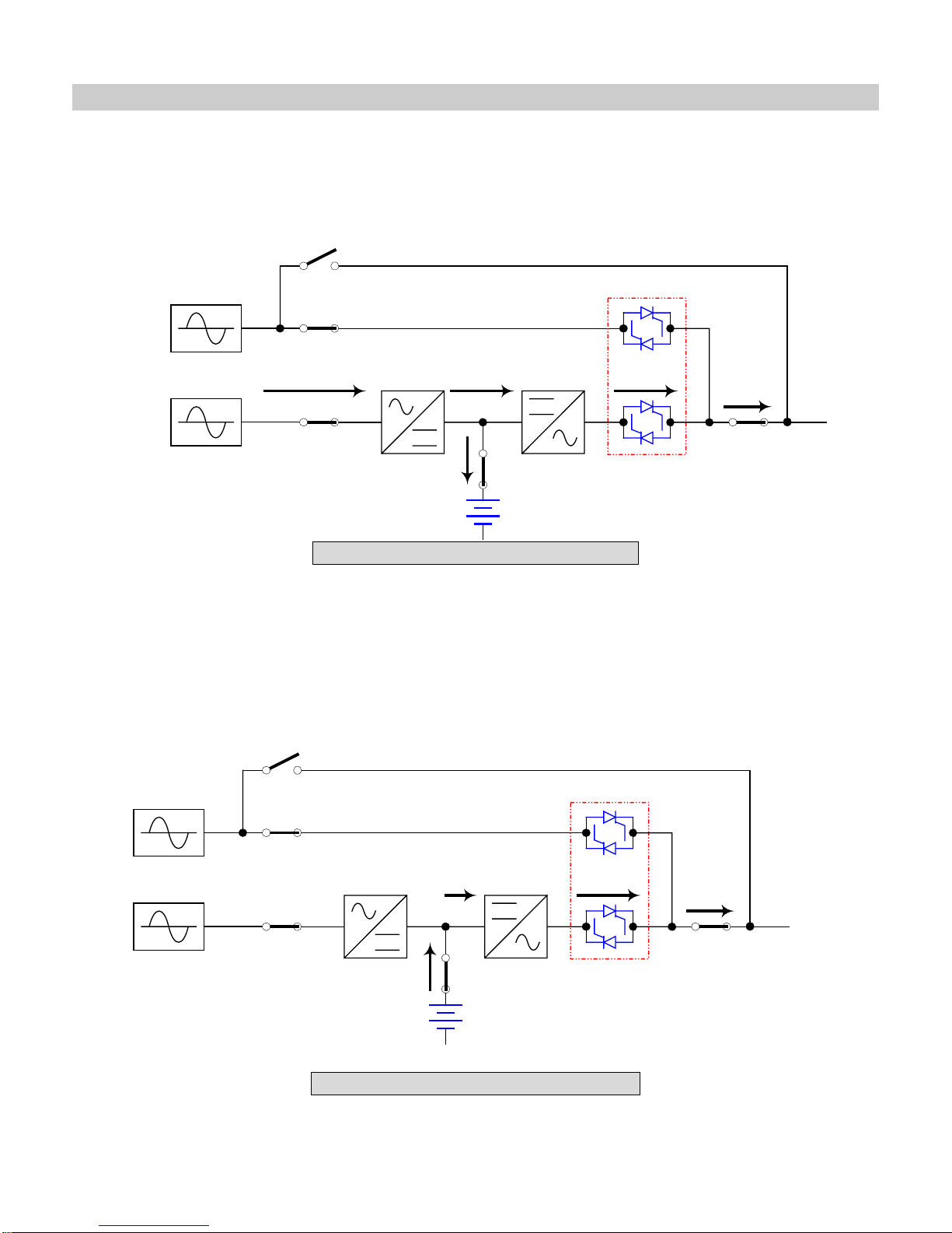
2-1 Normal Mode (Single Installation)
CB3
CB2
RESERVE
CB4
MAIN
CB1
CB5
STS
Fig. 2-1 Normal Mode Block Diagram
Under normal mode, util n transferred into DC power
ity power supplies to the rectifier and the
to supply the inverter and charge the batteries. Inverter will modulate and transfer the DC
power into AC power to the load. This the “Double Conversion” technology to regulate the
utility into pure and stable power to your precious equipment. (Refer to Fig. 2-1)
Backup Mode (Single Installation)
2-2
CB3
CB2
RESERVE
MAIN
CB1
CB5
STS
CB4
LOAD
LOAD
Fig. 2-2 Backup Mode Block Diagram
2-1
Page 10
When there is a power event (blackout, transient, surge, fluctuation…), UPS will
automatically switch from normal mode into backup mode. Battery (internal or external) wil
provide emergency pow er to Fig. 2-2)
er to the inverter and then the loads. (Ref
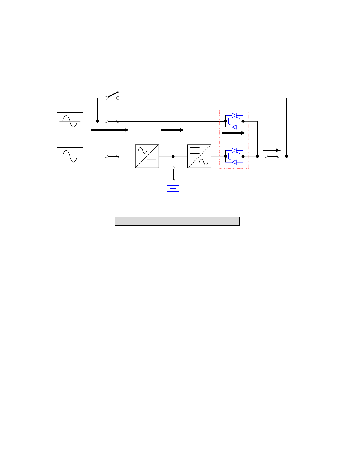
2-3
Reserve Mode (Single Installation)
CB3
CB2
RESERVE
l
MAIN
CB1
CB5
STS
CB4
LOAD
Fig. 2-3 Reserve Mode Block Diagram
When inverter malfunctions under(1)Over temperature (2)Overloading(3)Output shor
circuit(4)Output voltage abnormal(5)Battery terminates to backup, inverter will shutdown
If UPS detects the reserve power exists and normal, then UPS will automatically switch
into reserve mode to make sure the supply to the loads. When all troubles are eliminated
UPS will switch back Fig. 2-3)
to the normal mode immediately. (Refer to
t
.
,
2-2
Page 11

2-4 Bypass Mode (Single Installation)
CB3
CB2
RESERVE
MAIN
CB1
CB5
STS
CB4
LOAD
Fig. 2-4 Bypass Mode Block Diagram
Under maintenance or repair service condition, you will need to cut off the UPS power but
not the power to your equipment. Make sure the reserve power exists first, then manually
switch UPS into bypass mode. At this time, there is no power inside UPS. The servic e
engineer can do the maintenance or repair job safely but keep your equipment supplied.
(Refer to Fig. 2-4)
2-3
Page 12
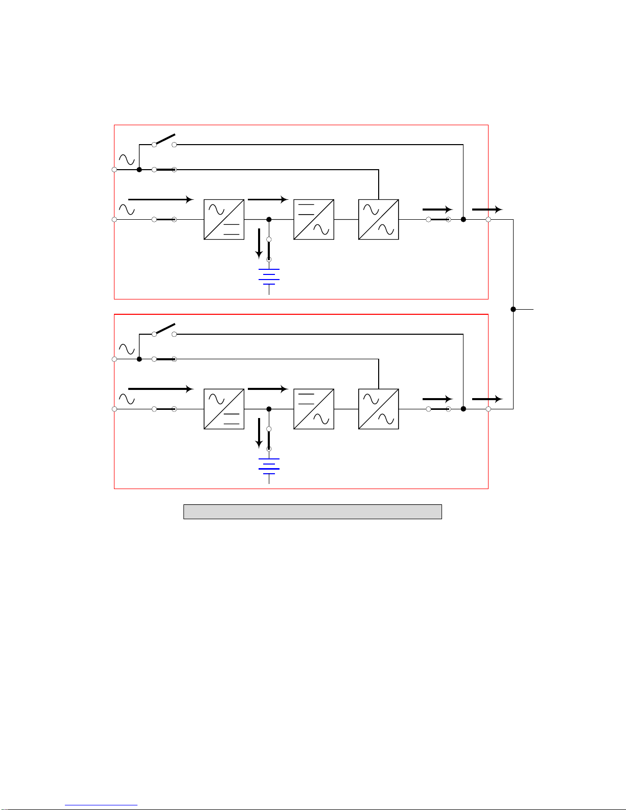
2-5 Normal Mode (Parallel)
elta NH-series provide 1+1 parallel combination to get redundancy or expand the total capacity.
D
CB3
CB2
RESERVE
MAIN
CB1
CB5
STS
CB4
UPS1
CB3
CB2
RESERVE
MAIN
CB1
CB5
CB4
STS
LOAD
UPS2
Fig. 2-5 Normal Mode in parallel redundancy
Under this inst
of them, the loading will be totally handle by another. In case the loading is greater than one
UPS can t
allation,the loading is shared by two UPS units. If there is something wrong in one
ake, UPS will shutdown and then switch to the reserve mode. (Refer to Fig. 2-5)
2-4
Page 13
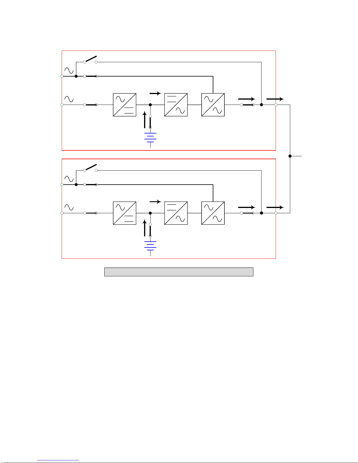
2-6 Backup Mode (Parallel)
CB3
CB2
RESERVE
MAIN
CB1
CB5
STS
CB4
UPS1
CB3
CB2
RESERVE
MAIN
CB1
CB5
STS
CB4
UPS2
Fig. 2-6 Backup Mode in parallel redundancy
Loading is shared by two UPS units when there is blackout. (Refer to Fig. 2-6)
LOAD
2-5
Page 14
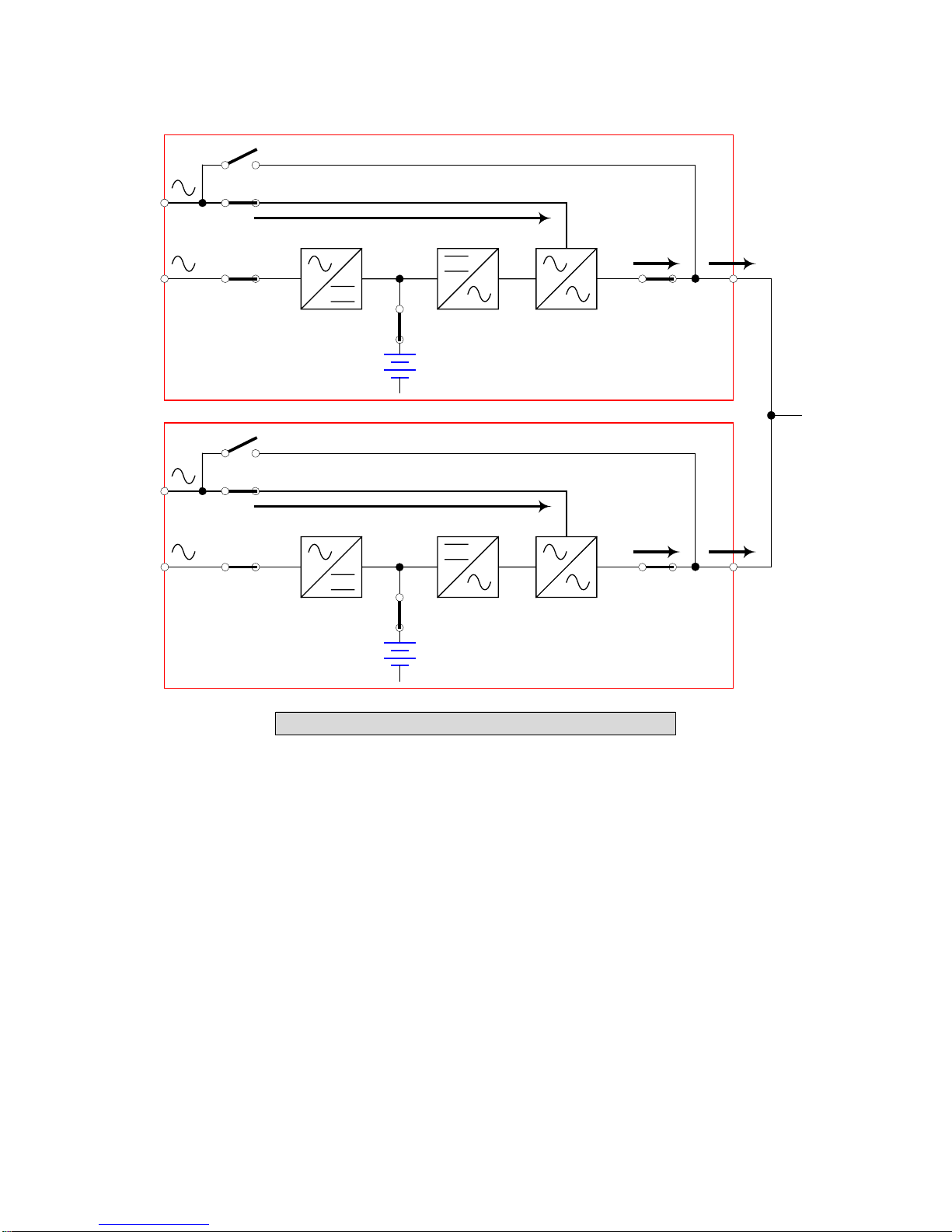
2-7 Reserve Mode (Parallel)
CB3
CB2
RESERVE
MAIN
CB1
CB5
STS
CB4
UPS1
CB3
CB2
RESERVE
MAIN
CB1
CB5
STS
CB4
UPS2
Fig. 2-7 Reserve Mode in parallel redundancy
The same as chapter 2-3 except two UPS share the loading. (Refer to Fig. 2-7)
LOAD
2-6
Page 15
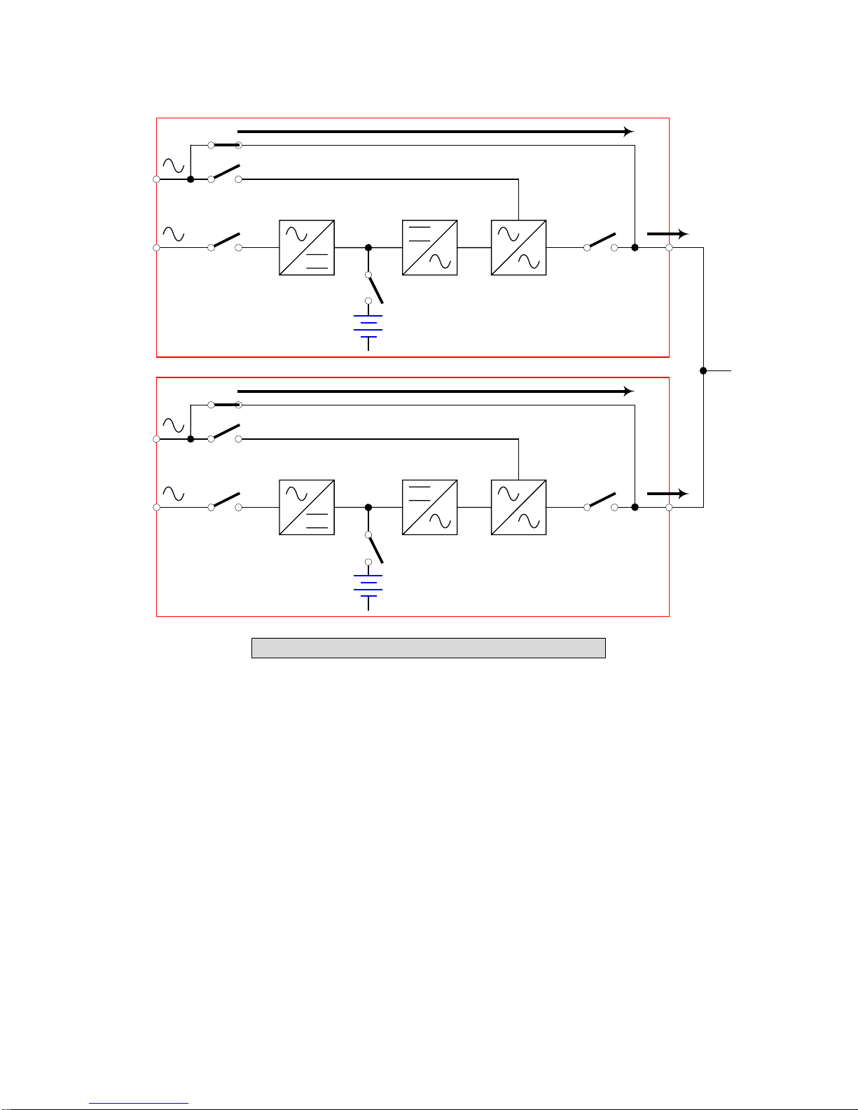
2-8 Bypass Mode (Parallel)
CB3
CB2
RESERVE
MAIN
CB1
CB5
STS
CB4
UPS1
CB3
CB2
RESERVE
MAIN
CB1
CB5
CB4
STS
LOAD
UPS2
Fig. 2-8 Bypass Mode in parallel redundancy
The same as chapter 2-4 except two UPS share the load. Remember that both UPS should
be switched into bypass mode. (Refer to Fig. 2-8)
2-7
Page 16
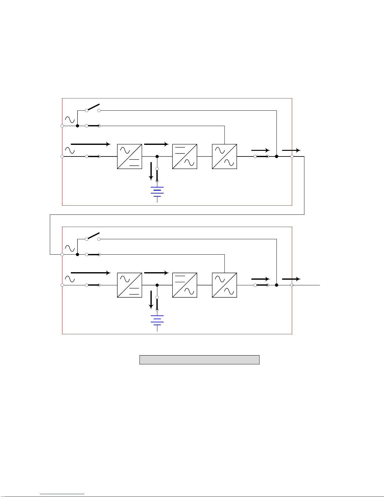
2-9 Hot Standby Redundancy
If you just want to double insurance the UPS operation, you can utilize one extra UPS to be
the reserve source of main UPS. This installation will make sure the output power
source for loading is still present even when the main UPS malfunctions.
(Refer to Fig. 2-9).
CB3
CB2
RESERVE
MAIN
CB1
CB5
STS
CB4
UPS1
CB3
CB2
RESERVE
MAIN
CB1
CB5
STS
CB4
LOAD
UPS2
Fig. 2-9 Hot Standby Redundancy
2-8
Page 17
3. General View
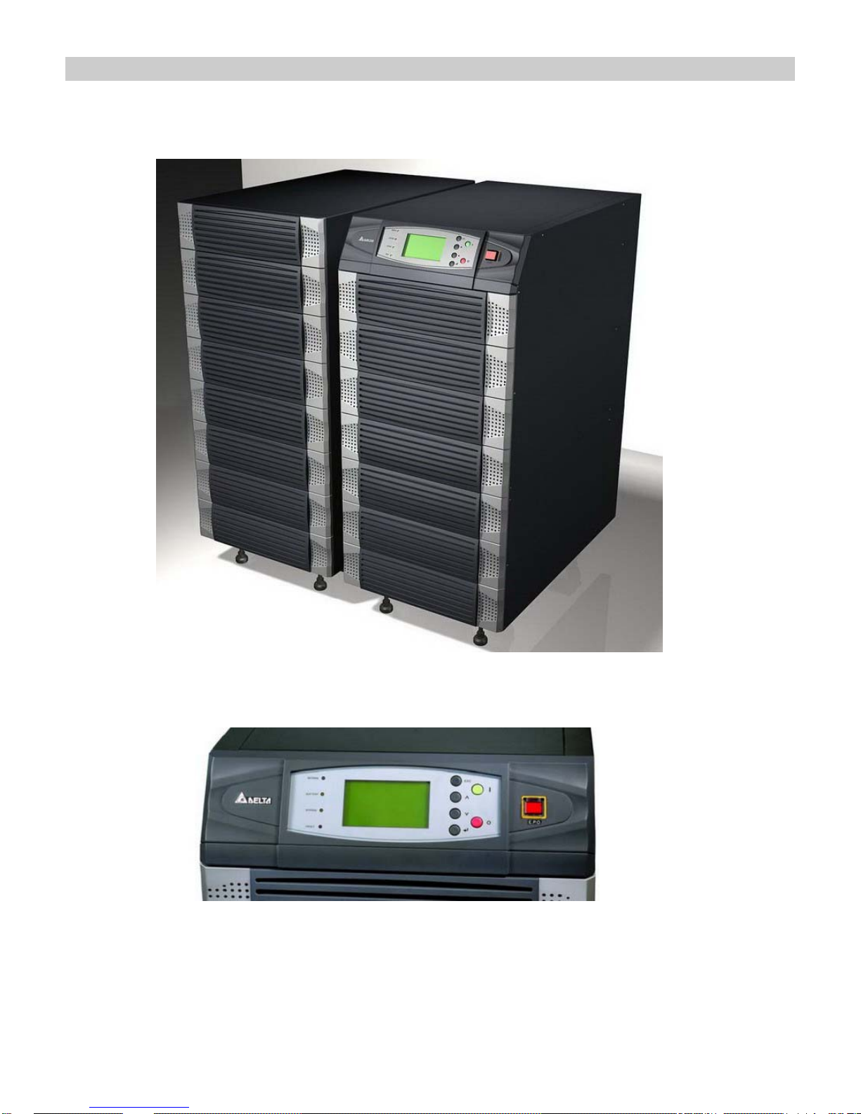
3-1. Appearance
External Battery
Pack
Power unit
LCD Display and Control Panel
3-1
Page 18
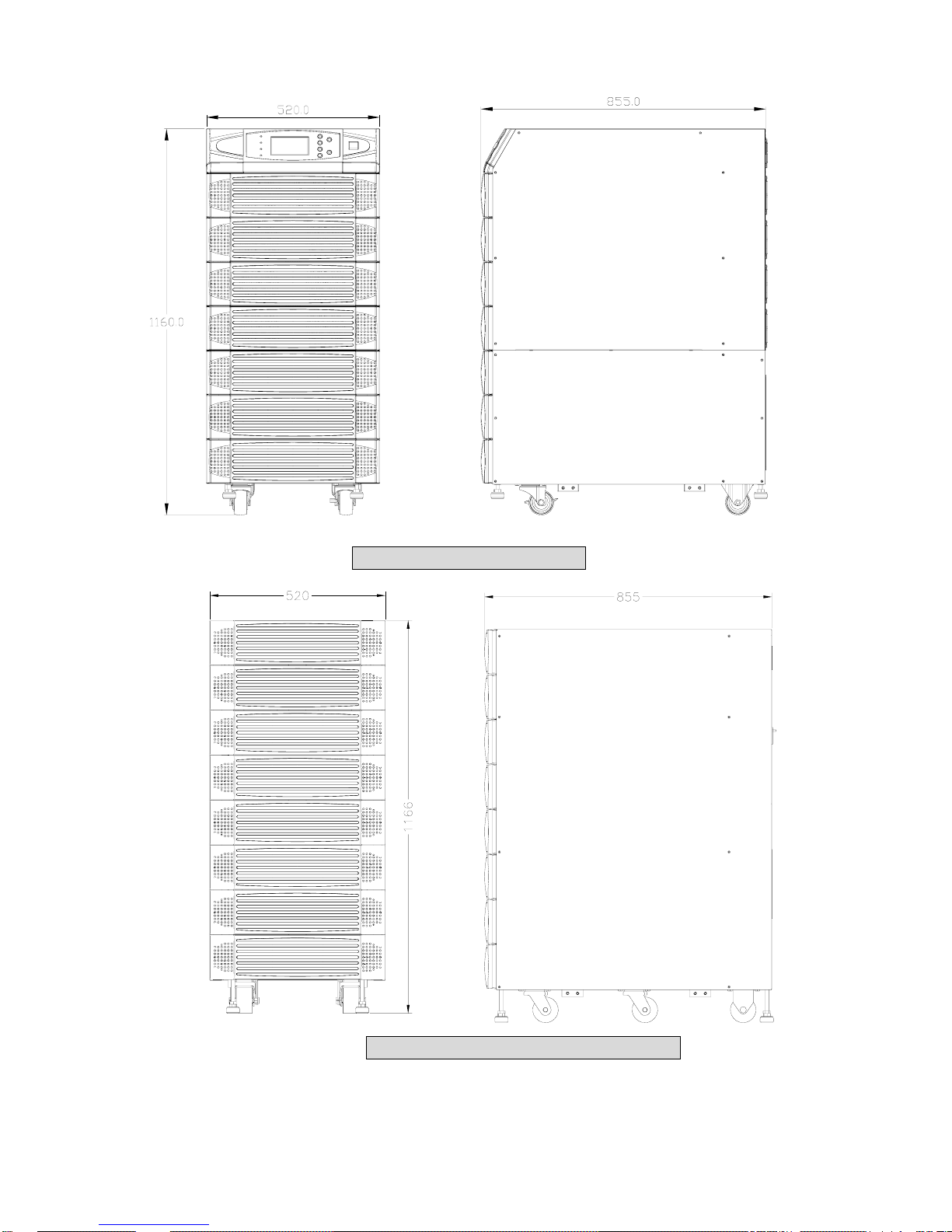
3-1-1 Dimension
Fig. 3-1 Power Unit (mm)
3-2 Function
Fig. 3-2 External Battery Pack (mm)
3-2
Page 19
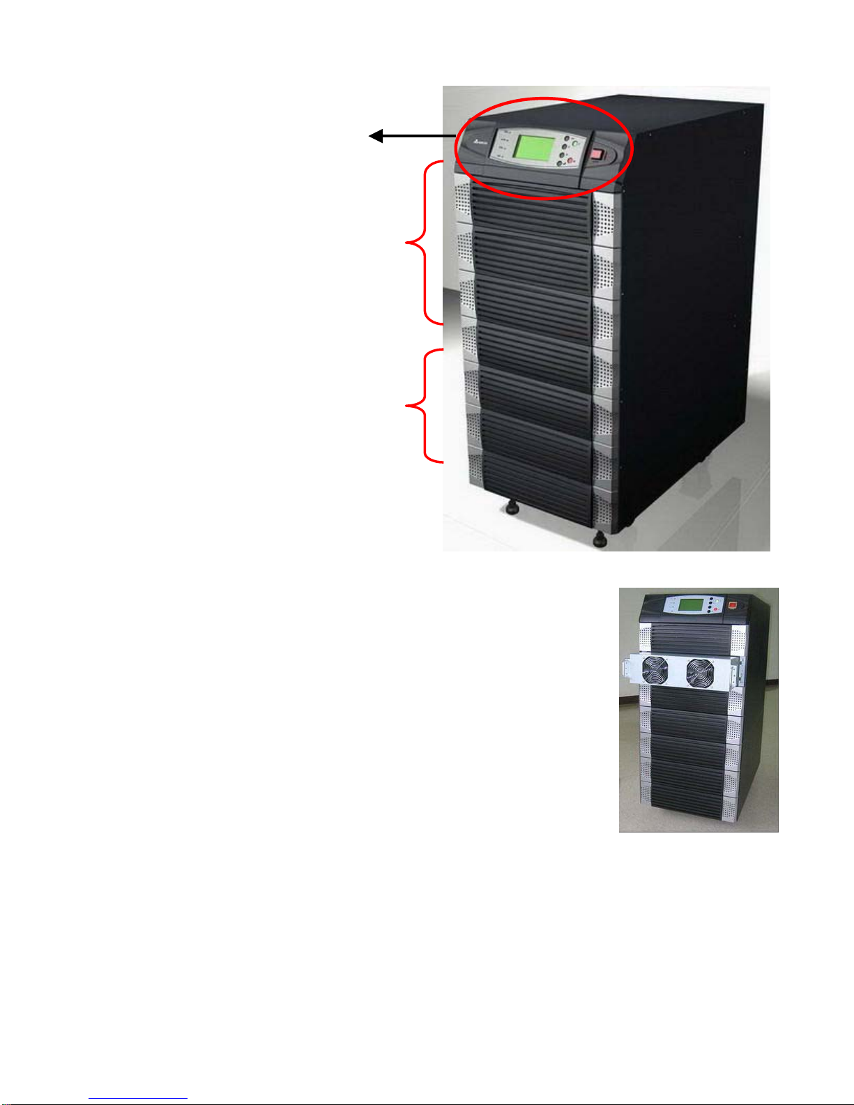
-2-1 Front Panel
3
LCD Display and
Control Panel
LED indicators
Power Modules
1. LCD Displa
/ LED indicators :
- Display UPS st
- Setup parameters and control buttons
- On/Off UP
- EPO: Emergency Power Off
Please refer to Chapter 6-1 for more det
ails.
2. Power Modules :
- Bezel can be easily removed for the purpose of maintenance.
- Minimum capacity of each power module is 15KV
(132cm) height.
Maximum modules can be t, i.e. maximum
I/P and O/P Protectors
y and Control Panel
atus and message
S
A, standard 3U
installed are four uni
capacity in a single cabinet is 80KVA
3. Protectors :
- Bezel can be easily removed for the purpose of installation or maintenance.
- There are four protectors: Input、Bypass、Manual Bypass、Output.
- All protectors are no fuse breaker ty
3-2- R
2 ear Panel
.
pe.
3-3
Page 20
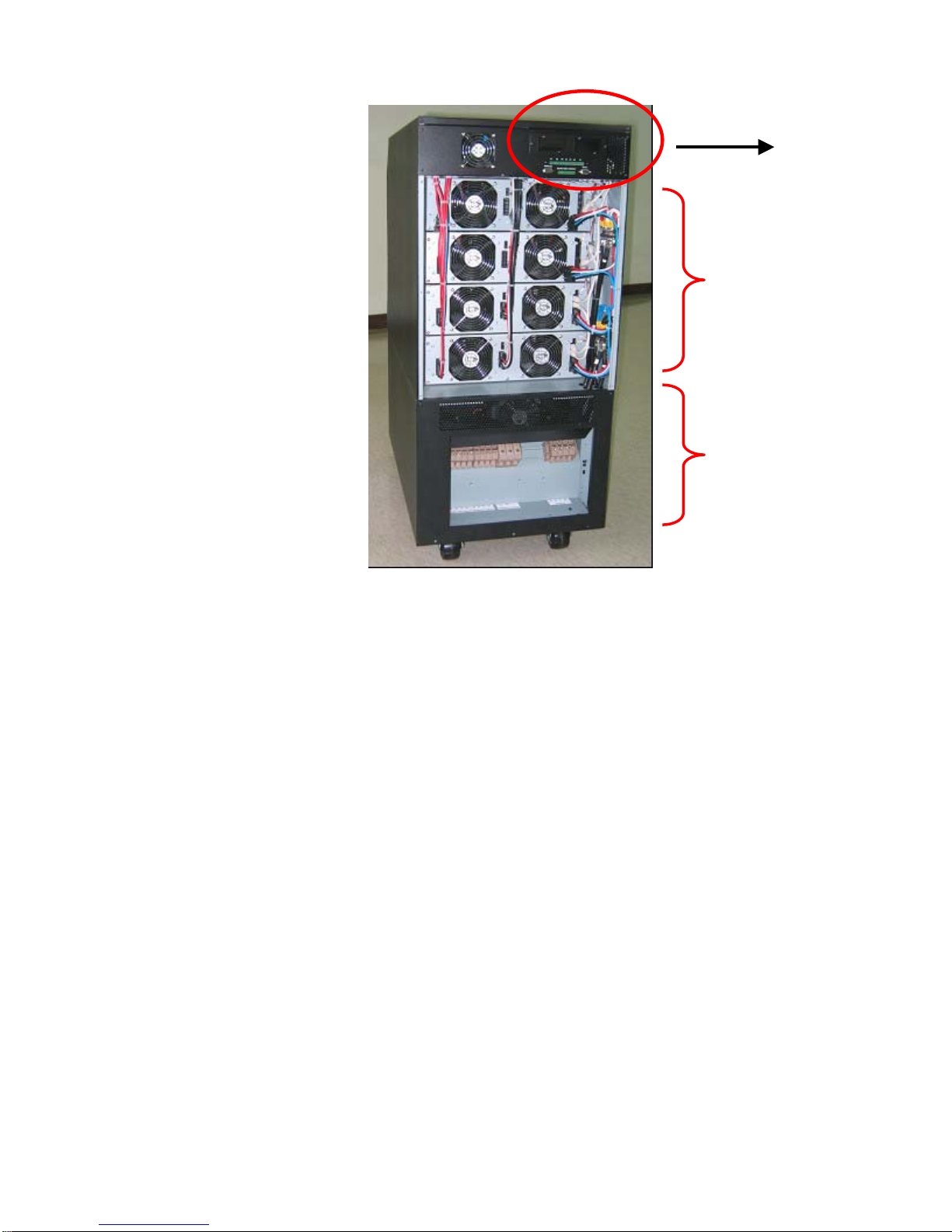
1. Interfaces:
Interfaces
Power Module
and Wiring
I/O Wiring Terminal
Block
- Provide multi-interface for monitoring and control purpose
- There are :
(1) Two multi-function slots (SNMP card、Relay I/O control card、Mobus card are optional
accessories)
(2) Parallel link communication
(3) Input and Output Dry Contact
(4) RS232 : Delta’s software ”UPSentry Smart 2000” or “InsightPower Manager” are
optional choice for central monitoring and control purpose)
2. Power Module and wiring:
- Remove the cover, you can perform wiring for power modules.
3. I/O wiring terminal block:
- Remove cover, you can perform wiring for input、output and external battery.
- Input power source : 3 phases ( R、S、T and neutral N )
- Bypass input source : 3 Phases ( R、S、T and neutral N )
- External battery pack : positive(+)、negative(-) and neutral N
- UPS output
: 3 Phases ( R、S、T and neutral N )
- Protection Earth : For safety
3-4
Page 21

3-3 pS ecification
Capacity 15kVA/12KW 20kVA/16KW 30kVA/24KW 40kVA/32KW 50kVA/40KW 60kVA/48KW 80kVA/64KW
Ra
ting Voltage V
Volt -25 ~ +20 age regulation %
Inp
Input
Output
Warni
Display
Remote
Interface
Others
Overall
ut current harmonic
distortion
PFC (Full Load) > 0.99
Frequency Hz 50 / 60
Frequency tolerance Hz
Output Voltage V 220/380 , 230/400 , 240/415 ( 3Φ 4W+Earth )
Output Frequency Hz 50 / 60
Total Harmonic (Linear Load) % ≦3
Voltage
regulation
Dynamic % ±7 (10% ~ 90% Linear Load)
Frequency
regulation
synchronized % ±5
Overload ≦125% : 10minutes ; ≦150% : 1minute
Battery backup Intermittent Audib
le
ng
U continuous
LED UPS status : Normal、Bypass、Backup、Fault
LCD
Monitor l data、Fault records retrievedMonitor up to 31 PCs、Graphically display records and historica
Control
Standard RS232, Dry Contact Output
Optional SNMP card, Modbus card, Relay I l sensor box, SNMP+5 Ports Hub/O control card, Environmenta
Parallel Redundancy Yes ( 1+1 for tw acity only!) o UPSs of the same cap
EPO Standard (Local and Remote)
SRAM event log Yes (500 records)
Parameter configuration Yes
Hot Standby Installation Feasible
Battery temperature
compensation
Battery Start Standard
Efficiency
Transfer Time ms 0
Temperature ℃ 0~40
Humidity (Non d) condense % 90
Noise (One meter) dBA 65 65 68 68 70 70 70
Dimension Width mm 520
Depth mm 850
(Full Load)
Static % ±1
Interior
oscillator
PS abnormal
Normal % 94
ECO % 97
Height mm 1165
Table 3-1 Delta NH-series Technical Data
220/380 , 230/400 , 240/415
( 3Φ 4W+Earth )
% < 5
45 ~ 65
Hz ±0.05
Input/Output、Bypass、Inverter、Frequency、Loading and Battery voltage、current
UPS abnormal message and intelligent self diagnosis
Remote control the Inverter and alarm、setup password、auto-dial warning
Optional
Weight Kg 125 125 175 175 210 210 244
3-5
Page 22

4. Installation
4-1 Before Installation
Due to different installation environment, we strongly recommend you to read this manual
carefully before installation. Only qualified service personnel can perform installation and
maintenance.
4-2 Package Inspections
External It’s not predictable that UPS or battery pack will suffer what kind of impact or
accident during transportation. We recommend you to inspect the container for any obvious
damage or mishandling.
Internal
1. When you unpack the container, immediately examine the UPS or battery pack cabinet.
2. Check the rating label on the rear side of cabinet. Confirm the model name and rating
match what you ordered.
3. Examine any parts is damaged or loosened.
4. Examine any accessory is missing. NH-series has the following accessory:
- RS232 cable : 1 pcs (Length = 1.8m)
- Parallel communication cable : 1 pcs (Length = 2m)
- Remote EPO -wiring connector : 1 set (2 contacts module)
- Input dry contact -wiring connector : 1 set (4 contacts module)
- Output dry contact –wiring connector : 1 set (12 contacts module)
- Software CD : 1 pcs
If the following condition happens:
- Any damage observed, either external or internal
- Any accessory is missing or damaged
Please contact your dealer or local agent for assistance
4-3 Storing for delayed installation
1. If the installation is not immediately performed after unpacking, please store UPS under:
- Temperature is below 40℃
- Relative humidity is below 90%
2. If the installation schedule will be over 6 months after you receive UPS, please recharge
batteries at least 8 hours before use.
4-1
Page 23

Charging procedure:
- Connect UPS to the utility. If external battery pack is ordered, please connect the
battery pack to the UPS.
- Start UPS. At this time, UPS will charge the battery by internal charging circuit.
3. Remain sealed as original packing. Prevent any possible damage from mouse or similar
creatures.
Connect and power the loading only when the battery is fully charged. It can make
sure that UPS can provide backup power to the loads when blackout occurs.
4-4 Unpacking procedure
4-2
Page 24

4-5 Location
4-5-1 Moving
1. NH-series UPS has casters to roll at a short distance to your desired location.
Under unpacking procedure, employ a suitable machine with sufficient capacity to
move UPS.
Please pay extremely attention when unbolt UPS from shipping pallet. Prevent any
accident caused by unexpected moving.
2. Casters are suitable for moving on even surface. Avoid moving UPS on bumpy route.
This may cause damage of UPS or tip-over accident.
3. When you need to move UPS for a long distance, please employ a suitable machine but
not by casters of UPS.
4. Refer to Table 4-1 to get the weight of UPS and external battery pack.
4-5-2 Positioning
1. Position UPS or external battery pack by suitable machine.
2. Refer to Table 4-1 and 4-2 , make sure to position UPS at a suitable floor which can
sustain for the weight.
3. When UPS has positioned, please make sure to use the stop of casters to remain UPS in
stable condition.
Table 4-1 Floor Loading for UPS
Input : 220/380 Vac / Output : 220/380 Vac
Capacity
(KVA)
Weight (Kg)
Floor
Loading
(kg/㎡)
15 20 30 40 50 60 80
125 125 175 175 210 210 244
283 283 396 396 475 475 552
4-3
Page 25

Table 4-2 Floor Loading for External Battery Pack
40 pcs
Capacity (Ah)
12V/26AH
Weight (kg)
470
Floor Loading
(kg/㎡)
1064
4-5-3 Environment
1. NH-series is for in-house use only.
2. The installation space should be conditioned at temperature 25oC, related humidity <90%.
3. Keep the circumstance neatly clean. Prevent any possible damage from mouse or similar
creatures, use suitable conduits for I/O wiring and severely protected..
4. UPS needs good ventilation and heat dissipation. NH series utilize fans to achieve heat
dissipation. The air-flow circulates from front to the rear bezel. Therefore, we strongly
recommend that :
(1) At least 100cm clearance in front of UPS to permit free passage of service engineer
and ventilation purpose.
(2) At least 50cm clearance between UPS rear bezel and wall to permit free passage of
service engineer and ventilation purpose.
(3) At least 50cm clearance between the top of UPS and the ceiling to permit free
passage of service engineer.
(4) At least 100cm clearance in front of external battery cabinet for maintenance and at
least 50cm between rear bezel and the wall for ventilation.
5. Recommend install fire extinguisher beside UPS for emergency use.
Don’t use any air conditioning or similar facilities that blow air directly onto the rear
side of UPS.
4-4
Page 26

4-6 Wiring
4-6-1 Preparations:
1. De-energize all input (AC or DC) or output power source of UPS before installing cables
or making any electrical connections.
2. Make sure that all cables are correctly marked according to the purpose. Also the
polarity, phase and diameter.
3. If UPS input/output power source is WYE-WYE (Y connection), then ”Neutral”
and ”Ground” should not be connected!
If input power source has VNG>0, the solution is install an isolation transformer before
UPS and input power source. Then connect “Neutral” and “Ground” of UPS together.
4-6-2 Wiring (Single Unit)
Notice:
Confirm the Ph-R、S、T of each cable.
Confirm the polarity of battery cable.
a. Connect battery’s 「+」、「-」and「N」 to UPS’s related terminal.
b. Connect ground of external battery cabinet to UPS’s ground.
Confirm the connection of UPS’s ground to protective earth.
Wrong cabling will result in severe damage of UPS and accident.
4-5
Page 27

Wiring procedure:
1. Remove cover at the rear side. See Fig. 4-1
Remover
Cover
Input
Bypass Input
External Battery
Output
Grounding
Terminal
Fig. 4-1 Wiring Terminal
Terminal block (Refer to Fig 4-1):
Input / Bypass : Ph-R、S、T and Neutral
Output : Ph-R、S、T and Neutral
External Battery : Positive(+), Negative(-) and neutral
Grounding : Protection
2. The rating voltage of standard model is 220/380VAC, 230/400VAC or 240/415VAC.
3. Battery rating voltage is ±240VDC. (12VDC / 20pcs x 2 strings)
4. Confirm input and bypass input circuit breaker (Q1 and Q2) are cut off (Refer to Fig.4-2)
5. Confirm manual bypass circuit breaker (Q3) is cut off.
4-6
Page 28

6. Confirm UPS output circuit breaker (Q4) is cut off.
7. According to UPS model you select, using suitable cable and lug (Refer to Table 4-3).
8. Connect all cables to the right terminal or location as indicated (Refer to Fig. 4-1).
Q4 Q3 Q2 Q1
Q1: Input Circuit Breaker
Q2: Bypass Input Circuit Breaker
Q3: Manual Bypass Circuit Breaker
Q4: Output Circuit Breaker
Fig. 4-2 Circuit Breaker
4-7
Page 29

Table 4-3 Input/Output Electrical Data
VA Input
(V)
15K 220/380 220/380 50 14 50 14 50 14 14 60
20K 220/380 220/380 50 14 50 14 50 14 14 60
30K 220/380 220/380 75 14 75
40K 220/380 220/380 75 14 75
50K 220/380 220/380 100 22 100
60K 220/380 220/380 125 22 125
Output
(V)
Input
Breaker
(A)
Cable
(mm²)
Reserve
Breaker
(A)
Reserve
Cable
(mm²)
14
14
22
22
Output
Breaker
(A)
75
75
100
125
Output
Cable
(mm²)
14 14 80
14 14 120
22 22 140
22 22 160
Battery
Cable
(mm²)
Battery
Fuse
(A)
80K 220/380 220/380 150 38 150
38
150
38 38 220
* Please follow the statute according to the installation region, select suitable breaker
and cable.
4-8
Page 30

4-6-3 Wiring (Parallel Redundancy, single input)
1. Confirm input and bypass input breaker (Q1 and Q2) is cut off (Refer to Fig. 4-2).
2. Confirm manual bypass circuit breaker (Q3) is cut off.
3. Confirm output breaker (Q4) is cut off.
4. According to UPS model you select, using suitable cable and lug (Refer to Table 4-3).
5. Connect all cables to the right terminal or location as indicated (Refer to Fig. 4-1).
6. Connect parallel communication cable between UPS1 and UPS2 (Refer Fig. 4-3).
1. For parallel redundancy installation, the total cable length of input must be equal
to output. This regulation prevent unbalanced loading share between two UPSs
under reserve mode.
i.e. : Res1 + OP1 = Res2 + OP2 (Deviation must be less than 10%)
2. Two UPSs must be the same rating/capacity for parallel installation. Different
rating can’t link to the other and may result in accident.
3. NH series can only parallel link to another one UPS ( 1+1 redundancy ), please
don’t parallel link more than two UPSs.
AC I/P
Res1
Reserve I/P
O/P
OP1
UPS1
IP1
Res2
Main I/P
Reserve I/P
Parallel Port
O/P
Parallel Cable
Load
OP2
UPS2
IP2
Main I/P
Fig. 4-3 Wiring (Parallel Redundancy, single input)
Parallel Port
4-9
Page 31

-6-4 Wiring (Parallel Redundancy, dual input)
4
1. Confirm input and bypass input breaker (Q1 and Q2) is cut off (Refer to Fig. 4-2).
2. Confirm manual bypass circuit breaker (Q3) is cut off.
3. Confirm output breaker (Q4) is cut off.
4. According to UPS model you select, us
5. Connect all cables to the right terminal or location as indicated (Refer to Fig. 4-1).
6. Connect parallel communication cable between UPS1 and UPS2 (Refer Fig. 4-4).
1. For parallel redundancy installation, the total cable length of input must be equal
to output. This regulation prevent unbalanced loading share between two UPSs
under reserve mode.
i.e. : Res1 + OP1 = Res2 + OP2 (Deviation must be less than 10%)
2. Two UPSs must be the same rating/capacity for parallel installation. Different
rating can’t link to the other and may result in accident.
3. NH series can only parallel link to another one UPS ( 1+1 redundancy ), please
don’t parallel link more than two UPSs.
AC I/P 2 AC I/P 1
ing suitable cable and lug (Refer to Table 4-3).
Res1
Reserve I/P
O/P
OP1
UPS1
IP1
Res2
Main I/P
Reserve I/P
Parallel Port
O/P
Parallel Cable
Load
OP2
UPS2
IP2
Main I/P
Fig. 4-4 Wiring (Parallel Redundancy, dual input)
Parallel Port
4-10
Page 32

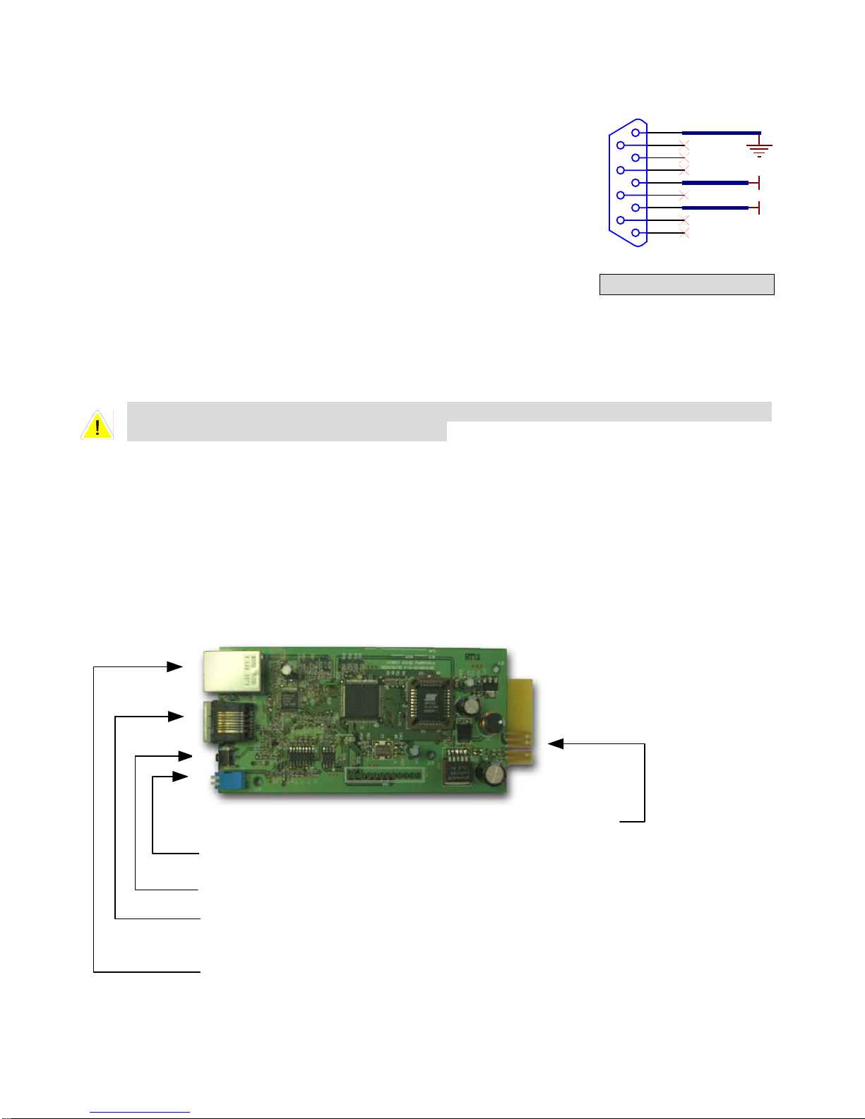
-7 Interface
4
Smart Card Slot
Parallel
Communication Port
-7-1 Input Dry Contact
4
P1:REPO (Remote Emergen
2:Input contact (Two sets)
P
P3:External Battery Cabinet Temperature 1
P4:External Battery Cabinet
P5:External Battery Cabinet Temperature 3
P6:External Battery Cabinet Temperature 4
P7:External Battery Status
1. P1 : REPO
NH series pr
ovide a convenient method to let the
user can shutdown UPS when an emergency
event happens.
Simply connect cable from remote site to this ter
switch thereby the user can easily push
Install a button or
the button to turn off UPS. This contact is normal open.
P1 P2 P3 P4 P5 P6 P7
PARALLEL
OUTPUT DRY CONTACT
Dry Contact Output
Fig. 4-5 Interface
cy Power Off)
Temperature 2
RS232
RS232 Com. Port
minal.
Input Dry Contact
1
2
12V
1
2
Fig. 4-6 REPO Circuit Detail
4
3
4-11
Page 33

2. P2 : Input Dry Contact (Two sets)
NH series provide two sets of dry con
receive external signals, then UPS can take
tact input to
1 12V
2
3
4
corresponding response.
These contacts are normal open.
Fig. 4-7 Input Dry Contact Circuit Detail
3. P3~P6 : External Battery Cabinet Temperature (Optional):
You can order this optional accessory to detect the temperature
4. P7 : External Battery Status (Optional)
Y ou can order this optional cable to detect
only for cabinet ordered from DELTA.
Pin1:+12V
al battery cabinet breaker’s status :
Pin2:Detection cable connected
Pin3:Extern
- Signal is active : breaker
- Signal is inactive : breaker is off
Pin4:reserved
Pin5:Reference voltage
the status of external battery cabinet. This function is
is on
1 4
12V
2 3
1 4
2 3
of external battery cabinet.
4-12
Page 34

4-7-2 Output Dry Contact
1
2
3
4
5
6
7
8
9
10
11
12
Fig. 4-8 Output Dry Contact Detail
COMM_A
DRYA_NO
COMM_B
DRYB _NO
COMM_C
DRYC _NO
COMM_D
DRYC _NO
COMM_E
DRYE_NO
COMM_F
DRYF _NO
4-13
+12VS
3 4
3 4
3 4
3 4
3 4
3 4
1 2
DR Y1
+12VS
1 2
DR Y2
+12VS
1 2
DR Y3
+12VS
1 2
DR Y4
+12VS
1 2
DR Y5
+12VS
1 2
DR Y6
Page 35

NH series provide 6 dry contact outputs. These contacts can be setup to normal open or
normal close. The default message is:
Contact Message Description
Pin1-2 Load on inverter UPS is working normally
Pin3-4 Load on auto bypass UPS is in bypass mode
Pin5-6 Mains1 input fail when
Utility is blackout or abnormal. UPS is in backup mode
load on inverter
Pin7-8 Battery low UPS is in backup mode, and the battery voltage is
close to the terminative limit. (Battery voltage is lower
than 220V)。
Pin9-10 Bypass input
abnormal
Bypass is abnormal(frequency、phase), the output
frequency will follow the rating
Pin11-12 Battery test failure Perform battery test, the battery voltage is lower than
default value.
There are another 13 choices:
Contact Message Description
7. Internal
Module’s communication is not normal
communication failure
8. External parallel
communication failure
9. Output overload
When parallel redundancy installation, the parallel
communication is not normal
The loading is over UPS rating output.
warning/shutdown
10. Power module fault
Module fails and UPS is shutdown
shutdown
11. Power module
Module has error. But UPS still can function normally
warning
12. EPO activated Emergency power off the UPS.
13. Load on manual
UPS transfers into manual bypass mode
bypass
14. Battery cabinet over
Temperature is too high
temperature
warning/shutdown
15. Output voltage
Output voltage is too high or too low
abnormal
16. Battery need replace Overdue for battery replacement (Compare with
system setup)
17. Bypass over
Bypass “static transfer switch” is over temperature
temperature
warning/shutdown
18. Battery ground fault Grounding error
19. Bypass static switch
Bypass “static transfer switch” is abnormal
fault
4-14
Page 36
p
g
g
4-7-3 RS232 Port
Connect with computer via RS232 cable of the accessory.
DELTA develops a lot of powerful soft wares such as “UPSentry Smart
2000”, “InsightPower Manager” to integrate UPS into your system.
Please see chapter 7 for detail information.
5
9
4
8
3
7
2
6
1
TX
RX
4-7-4 Parallel Communication Port
For redundancy or expansion installation, you simply connect two UPSs via parallel
communication cable.
Use the parallel communication cable within the accessory pack. Link UPS with
unsuitable cable may result in accident.
4-7-5 Smart Card Slot
NH series provide two smart slots and DELTA develops many powerful smart cards for different
applications.
1. SNMP Card (Optional)
Golden Finger: 12V DC, Communicate with
Di
Switch: Normal, Configuration, Pass Through and Sensor
Reset: Reset SNMP
Console Port: Connect to HyperTerminal for
confi
uration or
RJ45 Network Port: 10/100 M Auto-Ne
Fig. 4-9 RS232 Circuit
otiation ethernet
4-15
Page 37

Features:
SNMP agent and web server implemented for UPSSupport the following protocols: ARP, IP,
ICMP, SNMPv1, SNMPv3 USM, UDP, TCP, HTTP, FTP, TFTP, SMTP, BOOTP, SNTP, DN
and Telnet
Security login by MD5
Users level management
Firmware upgrade for new features through TFTP
Batch configuration through FTP
Save UPS event log and history values in EEPROM
Schedule shutdown, restart and test UPS
Wake On LAN packet to wakeup PC
Send e-mail and SNMP trap to notify users
Provide InsightPower Client software to protect public operating systems
Provide InsightPower Manager to monitor all of the UPS information in the network
Provide InsightPower EzSetting software to easily configure at the first time and upgrade
firmware
Technical Spec.
Network Connection RJ-45
Temperature
0~40℃
Humidity 10~80% (relative)
Input Power 9~24V DC
Power Consumption 1 Watt (Maximum)
Dimension (L x W) 130 x 60 mm
Weight 58 g
Dip Switch Mode
SW1 SW2 Mode
ON ON Configuration
ON OFF For Environmental Sensor
OFF ON Pass Through
OFF OFF Normal
4-16
Page 38

2. Programmable Relay I/O Card (Optional)
Features:
UPS status information presented as 6 contact closuresProgrammable output contacts,
monitors the UPS events that users really concern in different application practices
Configurable UPS shutdown delay time
Configurable input signal as shutdown UPS or battery test
Has the ability to protect up to 6 computers unattended shutdown gracefully
Technical Spec.
Input Power 8 ~ 20VDC
Temperature
Humidity 10 ~ 80 %
Power
Consumption
Dimension(L x W) 130x60mm
Weight 200 g
Relay I/O
R1~R6
Imput
1.2 Watt.(Maximum)
Maximum
DC Voltage
24V
24V
0 ~ 40℃
DC Current
1A
10mA
4-17
Page 39

I/O Definition
GND-R: Relay Grounding
Common: 12 ~ 24VDC
R1
R2
Input Power Fail
R3
R4
UPS in Bypass Mode
R5
R6
Input : Remote shutdown or battery test
Default
Summary Alarm
Battery Low
Overload
Over Temperature
Tx: Transmit to PC, connect to RS232 pin-2
Rx: Receive from PC, connect to RS232 pin-3
GND-C: Ground for configuration, connect to RS232 pin-5
SW1
SW2
OFF(Default) ON
Normal Open Normal Close
Default Settings Customized Settings
3. ModBUS Card (Optional)
Features:
Translate UPS RS232 protocol into another RS232 and RS422/485 Modbus protocol.Device
ID is adjustable by 8 dip switches, the value is from 0 to 255.
RS422/485 terminal resistor is selectable by dip-switch, easy to install.
Baud rate and parity options are also adjustable by dip switches.
2 LEDs to indicate communication status.
Input Power 8 ~ 20VDC
Temperature
0 ~ 40℃
Humidity 10 ~ 80 %
Power
Consumption
1 Watt. (Maximum)
Dimension (L x W) 130x60mm
Weight 150 g
4-18
Page 40

I/O Definition
GND Ground for RS232
RS232-Tx Tx to PC
RS232-Rx Rx from PC
RS422-T+
RS422-D+
RS422-T-
RS422-D-
T+ for RS422 or
D+ for RS485
T- for RS422 or
D- for RS485
RS422-R+ R+ for RS422
RS422-R- R- for RS422
4-8 Other Optional Accessories
1. Environmental Sensor:
Features:
Real-time temperature/humidity and other environmental condition monitoring.
Monitors the status of 4 user-provide contact devices to protect your critical equipments.
Technical Spec.
Temperature Range
0℃ ~ 65℃
Accuracy ± 2% of full scale
Humidity Range 10% ~ 90%
Accuracy
± 8% (full scale for 15~35℃)
Contact Input 4 sets
Pin-1 Common
Pin-2 Smoke
Pin-3 Fire
Pin-4 Water
Pin-5 Security
Contact Configuration Normal Open or Normal Close
Dimension (W x D x H) 60 x 50 x 18 mm
Weight 142 g
4-19
Page 41

2. SNMP+ 5 Ports Switching Hub
Features:
Fast ethernet 5 ports 10/100M smart switching hub
SNMP agent and web server implemented for UPS Support the following protocols: ARP,
IP, ICMP, SNMPv1, SNMPv3 USM, UDP, TCP,
HTTP, FTP, TFTP, SMTP, BOOTP, SNTP, DN and Telnet
Security login by MD5
Users level management
Firmware upgrade for new features
through TFTP
Batch configuration through FTP
Save UPS event log and history values
in EEPROM
Schedule shutdown, restart and test UPS
Wake On LAN packet to wakeup PC
Send e-mail and SNMP trap to notify users
Provide InsightPower Client software to protect public operating systems
Provide InsightPower Manager to monitor all of the UPS information in the network
Provide InsightPower EzSetting software to easily configure at the first time and upgrade
firmware
Technical Spec.
Network connection RJ-45
Temperature
0~40℃
Humidity 10~80% (Relative)
Input Power 12V DC
Power Consumption 4.5 Watt. (Maximum)
Dimension (W x D x H) 65x143 x 28 mm
Weight 320 g
Dip Switch Mode
SW1 SW2 Mode
ON ON Configuration
ON OFF
Environmental
Sensor
OFF ON Pass Through Mode
OFF OFF Normal
4-20
Page 42

5. Operating Procedure
r
5-1 Start up Procedure (Single Unit)
Preliminary Check:
All circuit breakers are cut off, including the breaker or fuse of the external battery
cabinet.
Confirm there is no voltage potential between NEUTRAL and Ground.
Confirm the input power source matches the rating (Voltage、frequency、phase and
battery ) of UPS you install.
Q4 Q3 Q2 Q1
Q1 : Input Circuit Breaker
Q2 : Bypass Input Circuit Breaker
Q3 : Manual Bypass Circuit Breake
Q4 : Output Circuit Breaker
Start up procedure:
1. If there is external battery cabinet connected, switch on the circuit breaker of battery
cabinet. Confirm Q3 is cut off.
2. Switch on the Q2 and Q4.
LCD display will be activated. After initializing process, LCD display will show ”ON
AUTO BYPASS”. In the meantime, UPS output is supplied by the bypass source and
the LED indicator ”BYPASS” turns on.
3. Switch on the Q1. If input power source is normal, UPS is ready to start up.
4. Press button ” I ” for 3 seconds until you hear a beep then release button. Inverter will
activate and synchronize with bypass source. UPS transfers from bypass into inverter
therefore output will be supplied by inverter. ”BYPASS” indicator turns off
and ”NORMAL” indicator turns on.
5-2 Battery Start (Single Unit)
1. Switch on circuit breaker of external battery cabinet and confirm Q3 is cut off.
2. Press button ” I ” for 3 seconds until you hear a beep then release button.
3. UPS starts up by DC-bus soft start. Inverter will activate and follow default frequency.
4. Inverter will supply UPS output, and ”BATTERY” LED indicator turns on.
5-1
Page 43

5-3 Powering Down (Single Unit)
This procedure will shutdown UPS and also the output for loads. Confirm all loads are
turned off first!
1. Press button ” O ” for 3 seconds until you hear a beep then release button.
If originally UPS is in
- normal mode : Then UPS will transfer to bypass mode. LCD display will show ”ON
AUTO BYPASS”
- Battery mode : Then UPS will shutdown Inverter and cut off the output power.
2. Switch off “Q1”.
3. Switch off “Q2”.
4. Confirm UPS turns off and all circuits are off.
5. If there is external battery cabinet connected, switch off the circuit breaker of battery
cabinet.
6. Switch off “Q4”.
5-4 Manual Bypass Start up (Single Unit)
If UPS is in normal mode, press button ” O ” for 3 seconds until you hear a beep then
release button. Then UPS will automatically transfer to bypass mode.
1. Confirm UPS is in bypass mode.
2. Switch on “Q3”.
3. Switch off “Q4”.
1. Only for maintenance purpose, you can turn on manual bypass switch “Q3”. If you
switch on Q3 under normal condition, then inverter will turn off and output will be
supplied by manual bypass source.
2. Manual bypass mode ensures that UPS supplies the loads from manual bypass
source. The service engineer can perform maintenance process at this mode
without interrupting the loads. At this moment, UPS is still energized by input power
source. If service personnel want to replace any circuit board or component, please
power down UPS (Refer to 5-3) first.
5-5 Start up Procedure (Parallel Redundancy)
Preliminary check:
1. All circuit breakers are cut off, including the breaker or fuse of the external battery
cabinet.
2. Confirm there is no voltage potential between NEUTRAL and Ground.
3. Confirm the input power source matches the rating (Voltage、frequency、phase and
battery ) of UPS you install.
For parallel redundancy installation, you must set the ID code of each UPS to be
“01” and “02” by configuring the control panel.
5-2
Page 44

Start up procedure:
1. Connect two UPS with parallel communication cable. Ensure the connector is fastened
to the DB9 port.
2. If there is an external battery cabinet is connected, switch on the breaker of external
battery cabinet.
3. Switch on “Q2” of each UPS. The LCD display will show ”ON AUTO BYPASS”.
4. Switch on “Q1” of each UPS.
5. Press button ” I ” for 3 seconds until you hear a beep then release button. Inverter will
activate and synchronize with bypass source.
6. Repeat step 5 for another UPS. When the inverter of both UPSs activate normally, they
will transfer to normal mode at the same time.
7. Check out the output voltage of both UPSs. The deviation of each phase between two
UPSs should be less than 5V. If it is confirmed, then switch on “Q4” of both UPSs.
5-6 Powering Down (Parallel Redundancy)
If you need to turn off one of the paralleled UPSs:
1. press button ” O ” of the UPS you want to turn off. Last for 3 seconds until you hear a
beep then release button.
- If the other UPS can take over the total loads, then the turn-off one will shutdown
inverter. LCD display shows ”LOAD NOT POWERED” for the turn-off one. The
working UPS shows ”ONLINE MODE”.
- If the total loads is greater than one UPS can take over, then both UPSs will
shutdown inverter and transfer to bypass mode. Both UPS shows ”ON AUTO
BYPASS”.
2. Switch off “Q1” and “Q4” of the UPS you want to power it off.
3. Switch off “Q2” of the UPS you want to power off.
4. When the UPS is totally powered off, the LCD display will de-energized.
5. Switch off the breaker of external battery cabinet connected.
5-3
Page 45

5-7 Manual Bypass Start ups (Parallel Redundancy)
Only for maintenance purpose, you can turn on manual bypass switch. If you switch
on Q3 under normal condition, then inverter will turn off and output will be supplied
by manual bypass source.
5-7-1 Online Mode transfers into Manual Bypass Mode
1. press button ” O ” of the UPS you want to turn off. Last for 3 seconds until you hear a
beep then release button.
- If the other UPS can take over the total loads, then the turn-off one will shutdown
inverter. LCD display shows ”LOAD NOT POWERED” for the turn-off one. The
working UPS shows ”ONLINE MODE”.
- If the total loads is greater than one UPS can take over, then both UPSs will
shutdown inverter and transfer to bypass mode. Both UPS shows ”ON AUTO
BYPASS”.
2. Repeat Step1 for another UPS.
1. Switch off “Q1” of both UPSs.
2. Confirm both UPSs are completely shutdown.
3. Switch on “Q3” of both UPS. Reserve power source supplies the loads. LCD display
shows ”ON MANUAL BYPASS”.
4. Switch off ”Q4” and ”Q2” of both UPSs. LCD display will be de-energized.
5. Switch off circuit breaker of external battery cabinet.
6. In this mode, only ”Q4” and terminal block has hazard voltage. Service personnel can
perform maintenance work.
5-7-2 Manual Bypass Mode transfers into Online Mode
1. Switch on the circuit breaker of external battery cabinet.
2. Switch on ”Q2” and ”Q4” of both UPSs.
Switch off ”Q3” of both UPSs. Both UPS shows ”ON AUTO BYPASS”.
3. Switch on ”Q1” of both UPSs.
4. Press on ” I ” for 3 seconds until you hear a beep then release button.
5. Repeat step5 for another UPS. When When the inverter of both UPSs activate
normally, they will transfer to normal mode at the same time.
5-4
Page 46

6. Display and Configuration
6-1. Control Panel
1. Normal (Green): Turn on when UPS input power is normal
2. Battery (Amber): Turn on when UPS is in backup mode
3. Bypass (Amber): Turn on when UPS is in manual bypass mode
4. Fault (Red): Turn on when any fault occurs
5. LCD Display: LCD screen, Multi-language (Chinese tradition/Big5, English)
6. ESC: page up
7,8. Configuration:
i and j : cursor up or down
9. ON: Press for 3 seconds to start up UPS (Inverter On)
10. OFF: Press for 3 seconds to power down UPS (Inverter Off)
11. EPO: Emergency Power Off. Press EPO will completely power down UPS
: Confirm setup
4
1
2
3
Fig. 6-1 Control Panel
5
6
9
7
10
8
11
6-1
Page 47

6-2 LCD Display
NH series UPS provide user-friendly LCD screen to show messages.
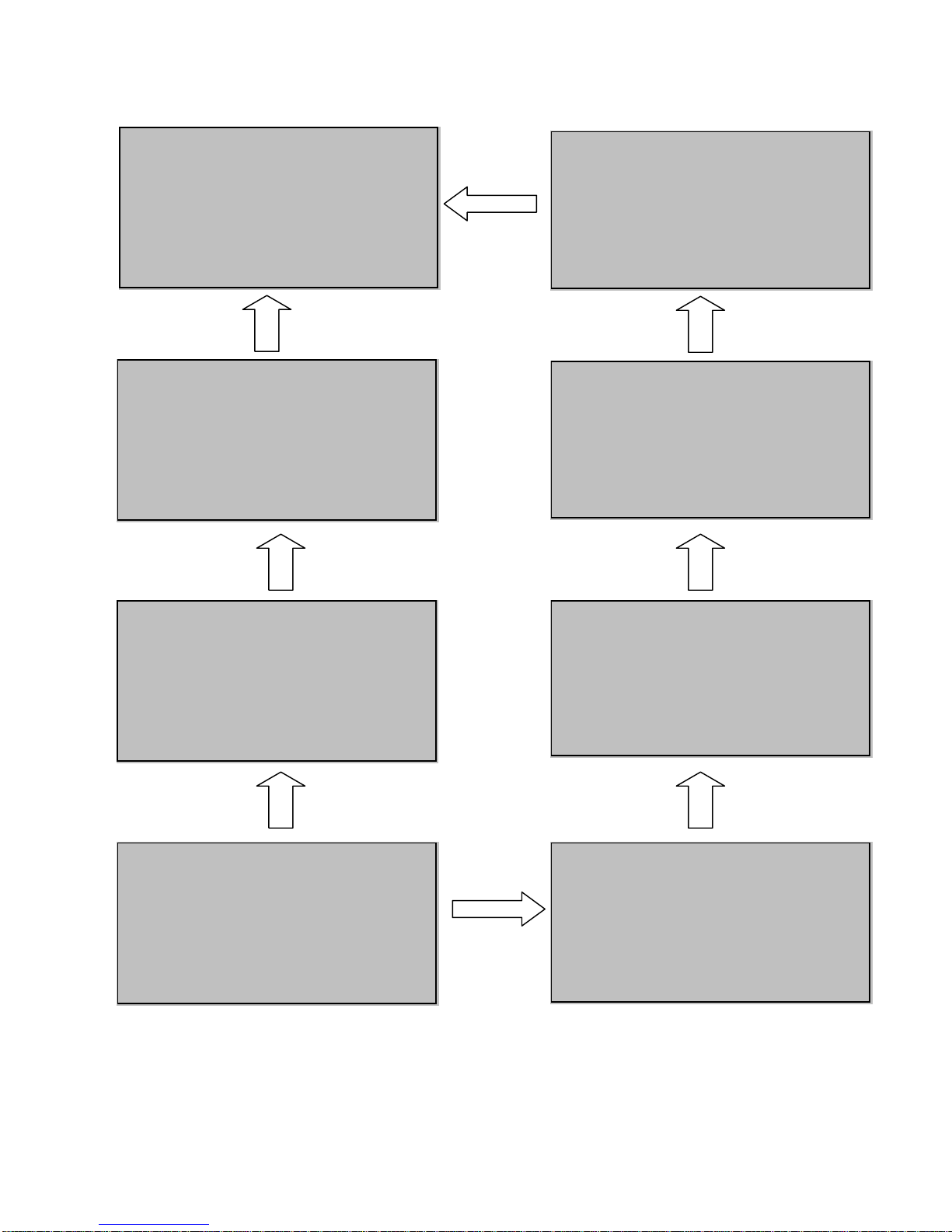
6-2-1 LCD Display Hierarchy:
Level 2
Measures &
Status
Level 3
Mains Input
V/Hz
Bypass Input
V/Hz
Inverter Output
Module 1/2/3/4
V/A/Hz
UPS Output
V/Hz
UPS Output Load
%/A/KVA/KW
Battery >>
V
Status
Capacity
Test Result
Temperature >>
Bypass STS
Module 1/2/3/4
PFC
Inverter
Level 1
Welcome/
UPS Diagram
Level 2
UPS Setup Maintenace
Level 1
Alarm/Fault Info
Level 2
Level 3
Bypass Setting >>
Voltage Range >>
Frequency Range >>
Output Setting >>
Inverter Voltage (220/230/240) >>
Inverter Frequency (50/60Hz) >>
ECO Mode (Enable/Disable) >>
Frequency Converter Mode >>
Battery Setting >>
EXT Battery Type >>
Charger Current >>
Battery Date >>
Auto Battery Test >>
Local Setting >>
Date/Time Change >>,
Password Change >> Admin/User >>
Parallel UPS ID Setting >>
Audible (Enable, Disable, Mute)>>
Display >>
Language >>
Serial COM ID >>
Redundancy Setting >>
DISABLE
1 Power module
2 Power module
3 Power module
4 Power module
Level 4/5
Level 4/5
Level 4/5
Level 4/5
Fig. 6-2 LCD Display Hierarchy
Level 3
Statistics
Read>>,
Reset>>
Event Log >>
Read >>,
Erase>>
Test >>
Force boost charge >>
Manual battery test >>
LED & Buzzer test >>
CLR BAT test result >>
FW upgrade
System FW >>,
Power Module FW >>
Other info.
S/N & FW version >>
System time >>
Module DCBUS Volt >>
Level 4/5
Level 4/5
Level 4/5
Level 4/5
Level 4/5
6-2
Page 48

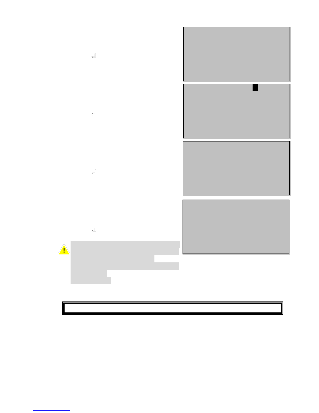
6-3 Default Screen
After UPS starts up and completes the self-test, screen will show:
LOAD UNPROTECTED
LOAD UNPROTECTED
ON AUTO BYPASS
ON AUTO BYPASS
BYPA.
BYPA.
MAINS
MAINS
!
!
1. When any event occurs, you will see the sign “!” flashes. You can press “j” to see
the details. For example :
KONQERF/TLOVNIAM
NIAM
KONQERF/TLOV
◆
◆
NIAM
NIAM
TUPNIKCEHC
TUPNIKCEHC
Press “j” again will go to the next message. If there is no further message, then the
screen will back to default screen.
2. Press “ESC” at any time will back to default screen.
6-3
Page 49

6-3-1 Status Display
LCD display will show the different status of UPS:
1.
2.
LOAD NOT POWERED
BYPA.
MAINS
This message means: The loads behind UPS are not powered. UPS cuts off the output.
Maybe due to:
- UPS automatically shutdown by itself.
- Manually switch off the output circuit breaker.
SOFT START…
ON AUTO BYPASS
BYPA.
MAINS
This message means: The loads are supplied power by bypass source
due to UPS startup initially
6-4
Page 50

3.
SOFT START…
BYPA.
MAINS
This message means UPS startup by battery power.
4.
LOAD UNPROTECTED
LOAD UNPROTECTED
ON AUTO BYPASS
ON AUTO BYPASS
BYPA.
BYPA.
MAINS
MAINS
!
!
This message means: UPS is in bypass mode. In the mean time, main power source and
battery are cut off. So the loads may loose power if the bypass source suddenly fails.
6-5
Page 51

5.
LOAD PROTECTED
ONLINE MODE
BYPA.
MAINS
This message means: UPS is operating under normal condition (normal mode).
6.
LOAD PROTECTED
ON BATTERY / BAT REM: 1123 MIN
BYPA.
MAINS
This message means: UPS is in battery backup mode. Loads are supplied by battery
power.
6-6
Page 52

7.
LOAD PROTECTED
ON BATTERY / BAT REM: 2 MIN
BYPA.
MAINS
This message means: UPS is in battery backup mode and remaining backup time
only 2 minutes left. Battery power is nearly exhausted.
8.
LOAD PROTECTED
BAT TEST
BYPA.
MAINS
This message means: UPS is performing “battery test”.
6-7
Page 53

9.
LOAD PROTECTED
ECO MODE
BYPA.
MAINS
This message means: UPS is in ECO (Economic Operation) mode. Loads are supplied
power by bypass source.
10.
LOAD UNPROTECTED
ON MANUAL BYPASS
BYPA.
MAINS
This message means: UPS is in manual bypass mode. When service personnel performs
the maintenance work, UPS must be transferred into this mode first.
In the mean time, main power source and battery are cut off. So the loads may loose power
if the bypass source suddenly fails.
6-8
Page 54

6-4 Main Menu
Press “ ” in default screen will change into the main menu:
E
E
R
R
U
U
SAEM
SAEM
P
U
SPU
SPU
S
T
T
E
E
S
P
U
A
N
A
N
E
E
T
T
NIAM
NIAM
ress “j” or ”i” to select desired item, then confirm by press
MEASURE
by “j” or ”i” to “Measure”. Select this item by press ” ”Move cursor .
Move cursor by “j” or ”i” to see all the status of UPS.
ECN
ECN
“P ”.
6-9
Page 55
NIAM
I
I
N
N
P
P
U
U
T
NIAM
2
0
0
.
2:R
2:R
2:S
2:S
.
2
2
2
0
0
.
.
zH0.05
zH0.05
S
S
SAPYB
SAPYB
0
0
22:R
22:R
..0
..0
22:S
22:S
zH0.05
zH0.05
M
REWOP
M
REWOP
E
T
REVNI
E
T
REVNI
.
0
.
0
z
H
0.05
z
H
0.05
OSPU
OSPU
U
U
T
T
22:R
22:R
0
0
.
.
22:S
22:S
0
0
.
.
zH0.05
zH0.05
T
0
0
V
V
/
/
0
0
V
V
YCNEUQERF
YCNEUQERF
U
U
P
P
N
N
I
I
3
3
/
/
V
V
0
0
3
3
/
/
V
V
0
0
YCNEUQERF
YCNEUQERF
L
UVD
O
O
R
R
0
0
P
P
0
0
0
0
L
UVD
O
O
/
/
YCNEUQERF
YCNEUQERF
U
U
T
T
V
V
/
/
V
V
YCNEUQERF
YCNEUQERF
VV008833/
VV008833/
V083/V0.022:T
V083/V0.022:T
T
T
8
8
VV008
VV008
V083/V0.022:T
V083/V0.022:T
3
#
3
#
T
U
TEU
TEU
T
U
5
.
2P1
2P1
A22:R
5
.
A22:R
A5.21/V0.022:S
A5.21/V0.022:S
A5.21/V0.022:T
A5.21/V0.022:T
VV008833/
VV008833/
V083/V0.022:T
V083/V0.022:T
6-10
EPMETn#E
EPMETn#E
AREPMETTNERUTEIBMA
AREPMETTNERUTEIBMA
/
/
0
0
7
7
2
2
+
+
:
:
T
T
L
L
O
O
R-A
R-A
H
H
C
C
:
:
S
S
U
U
T
T
A
A
T
T
9
9
:
:
Y
Y
T
T
I
I
C
C
A
A
P
P
A
A
D
AKO
L
T
UPTUO
UPTUO
01:R
01:R
L
T
/
0
/
0
0
.%0
0
.%0
D
AKO
0
2
0
2
V
V
A02/%001:S
A02/%001:S
A02/%001:T
A02/%001:T
%0CTAB
%0CTAB
001/AA
001/AA
E
RUTARLUDOM
E
RUTARLUDOM
05:CFP
05:CFP
℃
℃
05:RETREVNI
05:RETREVNI
℃
℃
03
03
℃
℃
ERUTAREPMETSTSSPB
ERUTAREPMETSTSSPB
06
06
℃
℃
V872VTAB
V872VTAB
ENIGSTAB
ENIGSTAB
%001
%001
SSAP:TLUSERTSETTAB
SSAP:TLUSERTSETTAB
WK0.01
WK0.01
WK0.001/AVK0.001
WK0.001/AVK0.001
WK0.001/AVK0.001
WK0.001/AVK0.001
Page 56

6-5 UPS SETUP
Before get into the “UPS SETUP”, you have to login first:
1. The login screen is as right. Move
cursor to select your correct ID, then
press ” ” to go to next page.
A
DMINISTRATOR: Qualified service
personnel
User: The
the parameter but not to configure
2. The password consists of 4 digitals.
Use “j” or ”i” to select the first
number then press ” ” will go to t
next digital. After all digitals are
select, press ”
3. If password is wrong, please
press ” ” to re-select.
4. If password is correct, screen will
show the setup menu.
ursor by “j” or ”i” to “Measure”. Select this item by press ” ”Move c
NIGOL
NIGOL
IMDA
IMDA
RESU
RESU
authorization is only to check
” to confirm ch
he
oice.
S
S
APYB
S
S
APYB
T
U
PTUO
T
U
PTUO
YR
E
TTAB
TTAB
YR
E
SEY
SEY
U
T
S
S
U
T
U
T
EES
U
T
EES
T
E
S
T
E
S
PUTESLACOL
PUTESLACOL
P
P
P
P
ROTARTSIN
ROTARTSIN
UOYERAERUS
UOYERAERUS
ROCNIDRO !TCERWSSAP
ROCNIDRO !TCERWSSAP
AGAYRTE
PU
PU
c
c
d
d
4321:DROWSSAPNIMDA
4321:DROWSSAPNIMDA
?
?
+
+
c
c
d
d
-
-
NISAELP AGAYRTE
NISAELP
c
c
d
d
6-11
Page 57

a. BYPASS SETUP
Move cursor by “j” or ”i” to “BYPASS SETUP”. Select this item by press ” ”
1. Move cursor by “j” or ”i” to select
“VOLTAGE RANGE” or
“FREQUENCY RANGE”.
Press ” ” to confirm the choice.
S
S
SAPYB
SAPYB
A
A
TLOV
TLOV
EGU
EGU
U
U
TCE
TCE
S
S
NPA
NPA
R
R
E
E
NEAGR
Y
Y
N
N
NEAGR
EGQERF
EGQERF
2. Move cursor by “j” or ”i” to select
voltage range then Press ”
confirm the choice.
” to
GATLOVS
GATLOVS
2E2
2E2
SEY
SEY
GNARSAPYB
GNARSAPYB
51±V0
51±V0
ERUSUOYERA
ERUSUOYERA
3. Move cursor by “j” or ”i” to select
frequency range then Press ”
confirm the choice.
” to
RQERFS
0A5
0A5
SEY
SEY
:EGNSAPYB
:EGNSAPYB
.
.
H0
5±
5±
H0
RQERFS
c
c
d
d
E
E
%
%
?
?
+
+
c
c
d
d
-
-
?zERUSUOYERA
?zERUSUOYERA
+
+
c
c
d
d
-
-
Press “ESC” will go back to “UPS SETUP” menu
6-12
Page 58

b. OUTPUT SETUP
Move cursor by “j” or ”i” to “OUTPUT SETUP”. Select this item by press ” ”
All the parameter in this segment can only be changed
under “Bypass Mode”.
1. Move cursor by “j” or ”i” to select
the desired item. Press ” ” to confirm
the choice.
UPTUO
UPTUO
TLOV
TLOV
QERF
QERF
S
S
T
T
E
E
A
A
N
N
EGU
EGU
PUYTCE
PUYTCE
EDOMCIMONOCE
EDOMCIMONOCE
c
2. Move cursor by “j” or ”i” to select
the desired output voltage. Press ” ”
to confirm the choice.
3. Move cursor by “j” or ”i” to select
the desired frequency. Press ” ” to
confirm the choice.
(This output frequency is for battery
start condition or when frequency
converter mode is enabled!)
4. Move cursor by “j” or ”i” to select
the desired mode. Press ” ” to
confirm the choice.
UPTUO
UPTUO
T
T
V
V
022
022
V
V
032
032
V042
9
9
9
9
9
9
V042
SEY
SEY
T
T
z
z
H05
H05
z
z
H06
H06
SEY
SEY
ONOCE
ONOCE
SID
SID
ANE
ANE
SEY
SEY
C
C
I
I
M
M
EEL
EEL
B
B
A
A
L
L
B
B
EGATLOV
EGATLOV
?ERUSUOYERA
?ERUSUOYERA
NEUQERF
YCUPTUO
NEUQERF
YCUPTUO
?ERUSUOYERA
?ERUSUOYERA
EDOM
EDOM
?ERUSUOYERA
?ERUSUOYERA
c
d
d
c
c
d
d
c
c
d
d
c
c
d
d
5. Move cursor by “j” or ”i” to select
the desired mode. Press ”
confirm the choice.
” to
RETREEV
N
N
O
O
C
C
L
L
B
B
A
A
SID
9
9
SID
E
E
L
L
B
B
ANE
ANE
SEY
SEY
RETREEV
?ERUSUOYERA
?ERUSUOYERA
EDOMQERF
EDOMQERF
c
c
d
d
EDOMRETREVNOCQERF
EDOMRETREVNOCQERF
Press “ESC” will go back to “UPS SETUP” menu
6-13
Page 59

c. BATTERY SETUP
Move cursor by “j” or ”i” to “BATTERY SETUP”. Select this item by press ” ”
All the parameters in this segment can only be changed
under “Bypass Mode”.
1. Move cursor by “j” or ”i” to select
the desired item.
Press ”
” to confirm the choice.
EPYTTABTXE
EPYTTABTXE
TNERRUCREGRAHC
TNERRUCREGRAHC
GNITTESETADTAB
GNITTESETADTAB
TSETTABOTUA
TSETTABOTUA
2. Move cursor by “j” or ”i” to select
the desired battery type and strings.
Press ”
(Type:26 / 40 / 100AH)
(String:1 / 2 / 3 / 4)
” to confirm the choice.
SEY
SEY
HA62:EPYTTAB
HA62:EPYTTAB
3:SGNIRTSTAB
3:SGNIRTSTAB
3. Move cursor by “j” or ”i” to select
the desired charging current.
Press ”
(Default:7A)
” to confirm the choice.
SEY
SEY
c
c
d
d
?ERUSUOYERA
?ERUSUOYERA
+
+
c
c
d
d
-
-
A7:TNERRUCREGRAHC
A7:TNERRUCREGRAHC
?ERUSUOYERA
?ERUSUOYERA
+
+
c
c
d
d
-
-
4. Move cursor by “j” or ”i” to select
the installation date and the next
replacing date.
Press ”
” to confirm the choice.
5. Move cursor by “j” or ”i” to select
the auto battery testing schedule.
Press ”
” to confirm the choice.
Press “ESC” will go back to “UPS SETUP” menu
6-14
ADLLATSN
ETITAB
ADLLATSN
ETITAB
)D/M/Y(01/21/6002
)D/M/Y(01/21/6002
ETADECALPERTXEN
ETADECALPERTXEN
)D/M/Y(01/21/6002
)D/M/Y(01/21/6002
+
?ERUSUOYERA
?ERUSUOYERA
SEY
SEY
OTUA
OTUA
ELBASID
9
9
SEY
SEY
ELBASID
YLIAD
YLIAD
YLKEEW
YLKEEW
YLKEEWIB
YLKEEWIB
YLHTNOM
YLHTNOM
TSETTAB
TSETTAB
?ERUSUOYERA
?ERUSUOYERA
+
c
c
d
d
-
-
c
c
d
d
Page 60

d. LOCAL SETUP
Move cursor by “j” or ”i” to “LOCAL SETUP”. Select this item by press ” ”
TESLACOL
1. Move cursor by “j” or ”i” to select
the desired item.
Press ” ” to confirm the choice.
2. Move cursor by “j” or ”i” to
change the “DATE/TIME”.
TESLACOL
MIT/ETAD
MIT/ETAD
DILELLARAP
DILELLARAP
ELBIDUA
ELBIDUA
YALPSID
YALPSID
EGAUGNAL
EGAUGNAL
EGNAHCE
EGNAHCE
EGNAHCDROWSSAP
EGNAHCDROWSSAP
DIMPOUCLAIRES
DIMPOUCLAIRES
NAHCEMITEG/ETAD
NAHCEMITEG/ETAD
Press ” ” to confirm the choice.
(This item is user accessible! )
SEY
SEY
?ERUSUOYERA
?ERUSUOYERA
3. Move cursor by “j
the desired item.
Press ” ” to confirm the choice.
” or ”i” to select
GNAHCDROEWSSAP
GNAHCDROEWSSAP
DROWSSAPNIMDA
DROWSSAPNIMDA
DROWSSAPRESU
DROWSSAPRESU
Move cursor by “j” or ”i” to change
the password.
Press ” ” to confirm the choice.
SEY
SEY
SSAPNIMD:DROWAWEN
SSAPNIMD:DROWAWEN
4. Move cursor by “j” or ”i” to setup
the ID of UPS for parallel redundancy
installation.
ress ”
P
” to confirm the choice.
SEY
SEY
0: DILELLARAP
0: DILELLARAP
c
c
d
d
)D/M/Y(03/21/6002
)D/M/Y(03/21/6002
)S/M/H(52:01:81
)S/M/H(52:01:81
+
+
c
c
d
d
-
-
c
c
d
d
4321
4321
?ERUSUOYERA
?ERUSUOYERA
+
+
c
c
d
d
-
-
?ERUSUOYERA
?ERUSUOYERA
+
+
c
c
d
d
-
-
6-15
Page 61
5. Move cursor by
the audible alarm.
“j” or ”i” to setup
Press ” ” to confirm the choice.
6. Move cursor by “j” or ”i” to s
the contrast of LCD screen.
Press ”
(This item is user accessible
” to confirm the choice.
!)
7. Move cursor by “j” or ”i” to select
the language of LCD screen.
Press ”
(This item is user
” to confirm the choice.
accessible!)
8. Move cursor by “j” or ”i” to setup
the ID of serial port.
Press ”
For standard RS 2 con ection, this23 n
” to confirm the choice.
ID is meaning less. If the connection
is via RS485/RS422 transfer
connec to RS232, then the ID
tor can
be setup to
00, 01…….99)
etup
ELBIDUA
ELBIDUA
ELBANE
9
9
SEY
SEY
9
9
SEY
SEY
ELBANE
ELBASID
ELBASID
?ERUSUOYERA
?ERUSUOYERA
c
c
d
d
5:TSARTNOCDCL
5:TSARTNOCDCL
?ERUSUOYERA
?ERUSUOYERA
SEY
SEY
+
+
c
c
d
d
-
-
EGAUGNAL
EGAUGNAL
HSILGNE
HSILGNE
ESENIHCNOITIDART
ESENIHCNOITIDART
ESENIHCELPMIS
ESENIHCELPMIS
?ERUSUOYERA
?ERUSUOYERA
c
c
d
d
10:DIMOCLAIRES
10:DIMOCLAIRES
?ERUSUOYERA
?ERUSUOYERA
SEY
SEY
+
+
c
c
d
d
-
-
Press “ESC” will go back to “UPS SETUP” menu
6-16
Page 62

6-6 Maintenance
o ” to the ”MAINTENANCE” in the main menu,
vne cursor “j” or ”iM
e m
1. Move cursor by “j” or ”i” to select
the desired item.
Press ”
2. Move cursor by “j” or ”i” to read
the statistic data.
Press ” ” to confirm the choice.
Statistic data example
Execute “RESET” function will reset all
statistic data
(This item is only accessible for
administrator!
confirmed again
”. confir by press “th
” to confirm the choice.
Password will be
!)
6-17
ECNANETNIAM
ECNANETNIAM
CITSITATS
CITSITATS
GOLTNEVE
GOLTNEVE
TSET&PUTESLAUNAM
TSET&PUTESLAUNAM
EDARGPUERAWMRIF
EDARGPUERAWMRIF
SREHTO
SREHTO
c
c
d
d
SCITSITATS
SCITSITATS
DAER
DAER
TESER
TESER
c
c
d
d
:YRETTABNOSTNUOC
:YRETTABNOSTNUOC
001
001
:SSAPYBNOSTNUOC
:SSAPYBNOSTNUOC
121
121
EMITNOITAREPOLATOT
EMITNOITAREPOLATOT
)D/Y(003/20
)D/Y(003/20
)M:H(52:01
)M:H(52:01
SCITSITATSTESER
SCITSITATSTESER
?ERUSUOYERA
?ERUSUOYERA
SEY
SEY
c
c
d
d
Page 63

2. Move cursor by “j” or ”i” to select
the desired item.
Press ” ” to confirm the choice.
Event log example
xecute “ERASE EVENT LOG”
E
function will reset all statistic data
(This item is only accessible for
administrator! Password will be
confirmed again!)
3. Move cursor by “j” or ”i” to select
the desired item.
Press ”
” to confirm the choice.
Press “
BOOST CHARGE”.
(This item is only accessible for
administrator! Password will be
confirmed again!)
” to execute “FORCE
GOLTNEVE
GOLTNEVE
DAER
07-07-03 13:17:00
07-07-03 13:17:00
UPS State:Load on Inverter
UPS State:Load on Inverter
07-07-03 13:15:57
07-07-03 13:15:57
Input Voltage Normal
Input Voltage Normal
07-07-03 13:15:57
07-07-03 13:15:57
Input Frequency Normal
Input Frequency Normal
07-07-02 13:15:54
07-07-02 13:15:54
UPS State: Load on Bypass
UPS State: Load on Bypass
07-07-02 13:15:53
07-07-02 13:15:53
Input Frequency Abnormal
Input Frequency Abnormal
07-07-02 13:10:16
07-07-02 13:10:16
Input Voltage Abnormal
Input Voltage Abnormal
DAER
ESARE
ESARE
EVENT LOG
EVENT LOG
SEY
SEY
SEY
SEY
GOLTNEVEESARE
GOLTNEVEESARE
c
c
d
d
?ERUSUOYERA
?ERUSUOYERA
c
c
d
d
TSET&PUTESLAUNAM
TSET&PUTESLAUNAM
EGRAHCTSOOBECROF
EGRAHCTSOOBECROF
TSETYRETTABLAUNAM
TSETYRETTABLAUNAM
TSETDELDNAREZZUB
TSETDELDNAREZZUB
TLUSERTSETTABRLC
TLUSERTSETTABRLC
c
c
d
d
EGRAHCTSOOBECROF
EGRAHCTSOOBECROF
?ERUSUOYERA
?ERUSUOYERA
c
c
d
d
6-18
Page 64

Press “ ” to execute “MANUAL
ATTERY TEST”. B
(This item is only accessible for
a to
dministra r. Password will be
c a
nfirmed gain!) o
Press “ ” to execu
ED TEST”.
L
(This item is only accessible for
administrator! Password will be
confirmed again!)
te “BUZZER AND
Press “
TEST RESULT”. This will clear all
battery test results in log.
” to execute “CLR BAT
4. Move cursor by “j” or ”i” to select
the desired item.
Press ” ” to confirm the choice.
(This item is only accessible for
administrator! Password will be
confirmed again!)
5. Move cursor by “j” or ”i” to select
the desired item.
Press ” ” to confirm the choice
- SN & FW version
and firmware version of UPS
- System Time: Date and time
- Module DC Bu
voltage of DC bus. Service
personnel can confirm it when
perform maintenance.
: serial num
s volt: The remaining
.
ber
TSETYRETTABLAUNAM
TSETYRETTABLAUNAM
?ERUSUOYERA
?ERUSUOYERA
SEY
METSYS
METSYS
SREHTO
SREHTO
SEY
c
c
d
d
TSETDELDNAREZZUB
TSETDELDNAREZZUB
?ERUSUOYERA
?ERUSUOYERA
SEY
SEY
c
c
d
d
TLUSERTSETTABRLC
TLUSERTSETTABRLC
?ERUSUOYERA
?ERUSUOYERA
SEY
SEY
EDARGPUERAWMRIF
EDARGPUERAWMRIF
ELUDOMREWOP
ELUDOMREWOP
c
c
d
d
NOISREVWF&NS
NOISREVWF&NS
EMITMETSYS
EMITMETSYS
TLOVSUBCDELUDOM
TLOVSUBCDELUDOM
c
c
d
d
Press “ESC” will go back to “Main Menu”
6-19
Page 65

7. Power Management Software
7-1 DELTA Software Family
Communication Port
RS232 USB RS485 SNMP
InsightPower Client
◆
UPSentry Smart 2000
◆◆
InsightPower Manager
◆◆
Shutdown Agent
◆
◆
Application
Shutdown OS
entralized ManagementRemote Monitoring
InsightPower Client
◆◆
UPSentry Smart 2000
◆◆
InsightPower Manager
◆◆
Shutdown Agent
◆
Support OS
Windows Linux FreeBSD Mac OSX SCO Sun Solaris HP-UX IBM AIX
InsightPower Client
◆
UPSentry Smart 2000
◆◆◆ ◆ ◆ ◆ ◆ ◆
InsightPower Manage
r
◆
Shutdown Agent
◆◆◆ ◆ ◆ ◆ ◆ ◆
7-1
Page 66

7-2 UPSentry Smart 2000
DELTA develops a power software family to easily integrate UPS into your system. “UPSentry
Smart 2000” supports all popular OS such as Windows, Linux, FreeBSD …etc.
Advanced Features:
Supports RS232 and USB protocols
Multi-lingual design (English, French, German, Spanish, Portuguese, Italian, Polish,
Chinese and Japanese)
Multi-servers shutdown/wakeup in various operating systems, use the Master/Slave
software structure need not to purchase another SNMP card
Unattended operating systems shutdown and files saving
Supports Windows hibernation feature
Programmable actions(FlexAction)
Remote and local UPS real-time management
Supports SNMP get, set and trap commands
Built-in mini Web server
Support OS:
Microsoft Windows 95, 98, Me, NT4, 2000, XP, 2003, Vista
Mac OSX
Linux
FreeBSD
SCO OpenServer
Sun Sparc and x86
HP-UX
IBM AIX
Main Frame
7-2
Server
PC / Workstation
RS232/
USB
Power Line
Router
Shutdown server
Shutdown
workstations after 10
minutes
when battery low
Remote Shutdown PC
Page 67

7-2-1 Flexible Management Tools
“UPSentry Smart 2000” provides powerful tools for administrator
of data center, MIS, IDC.
1. Real-Time Monitoring, record and analysis
Real-Time meters: 4(single phase)or 12(3 phases)meters.
Each meter is user-defined to display power information
(voltage, current, frequency…) or UPS’s status.
7-3
Power Events: Record date/time/description of power events such
as blackout
、power recover、bypass etc.
Provide data for administrator to analyze and print out.
Historical Data: Record (by graphic) the input/output
voltage/frequency
、loading、battery volts、UPS model 、fault
etc.
Block diagram and status: Display UPS status in
graphical format. Such as input/output voltage/frequency
、
battery volts、backup time.
2. Power Event Management
“UPSentry Smart 2000” provides a lot of flexible tools to
manage different power events or UPS status
(Blackout、
recover、battery low、overload、fault、battery test etc.).
Administrator can formulate a contingency plan in advance to handle
all kinds of threats from power events.
Programmable action for power event
UPS status chart
Real-time meters
UPSentry Smart 2000 provides flexible actions:
(1) Gracefully shutdown PC/Server
(2) Event log
(3) Network broadcast
(4) Auto-paging
(5) email
(6) SMS (short message)
(7) Audible alarm
(8) Execute external command
Moreover, “delay” setup can block frequently
meaningless transients. For areas of unstable
power quality, administrator won’t suffer from
many notifications only when true power events
happen.
Page 68

7-4
. Overload Warning Setup
o stage of overload limit between 0%-100%. Warning message
4. Scheduled Shutdown/Auto Restart
shutdown process before UPS turns off. All the
, administrator can plan a shutdown and restart schedule to meet user-defined
5. udible Warning Message
re-record voice message and text.
the pre-record voice
Shutdown OS
Event Log
Popup
Message
Execute External
Command
Transmit an
audible message
3
Administrator can setup tw
will popup when reach the loading limit.
UPSentry Smart 2000 can perform OS
process is automatically proceeding to protect precious, critical equipment, and also the
data.
Besides
application.
A
Administrator can prepare a p
When power event happens, “UPSentry Smart 2000” will transmit
message and popup the text.
Page 69

7-3 InsightPower Manager
For data center or large scale factory, administrator need a convenient tool to centrally
control and monitor UPSs. DELTA develops “InsightPower Manager” to achieve this
purpose.
Features:
2F3F2F2F
3F3F
Centralized UPS
management system via
TCP/IP network
Supports RS232, RS485 and
SNMP connections
Supports database
connection through ODBC
Hierarchical design, allows
unlimited nodes
Client/Server design, multiple
remote Monitor programs can c
to a Service program
7-5
onnect
Programmable actions
Batch SNMP configuration
Remote and local UPS real-time management
Generate routine reports
Schedule shutdown/restart and test UPS
save the users operation log, UPS event log and historical parameters in database
Centralized Management
Hierarchical structure
Display:
1. Display: Display UPS status by group or
individual.
2. Hierarchical structure: Show the UPS
location and the related condition.
3. Multiple views formats: Meters, block
diagram, lamp alarms, graph chart.
Power Event Management:
Event log
Network broadcasting
Audible alarm
Email
SMS(short message) notification
Page 70

Event Log:
Record events and operation by date/time
Generate historical report and can be transferred into EXCEL file
Setup a periodically analyzing report.
SNMP
SNMP
SNMP
InsightPower
Manager Service
RS232/485
RS232/485
Network
InsightPower
Manager Monitor
InsightPower
Manager Monitor
Remote UPS Monitoring
7-6
 Loading...