


Copyright Notices
The information contained in the user’s manual and all accompanyied docu-
mentation are copyrighted and all rights are reserved. This publication may
not in whole or in parts, be reproduced, transcribed, stored in a retrieval
system translated into any languages or transmitted in any form without the
prior written consent from the manufacturer, except for copies retained by
the purchasers for their personal archival purposes.
Trademarks
z Award Modular BIOS is a registered trademark of Award Software Inc.
z Microsoft and Windows 95/98/NT are registered trademarks of Microsoft
Corporation.
z Intel Pentium, Pentium II, Pentium III, Celeron and Slot1 are registered
trademarks of Intel Corporation.
All other product names mentioned herein are used for identification pur-
poses only and may be the trademarks of their respective companies.
Technical Support
If you need technical assistance, our technical support engineers will be
glad to assist you with all technical difficulties, you can reach them by dial-
ing our toll-free service and technical support number : 1-877-DELTA-2K/1-
877-335-8225 (USA / CANADA Only ). Not only you will get to speak with
our experience technical support team, we also provide web-site address
(http://pc.delta.com.tw), product ,sales and RMA/warranty information. Our
skillful technical engineers will be available between 8:00AM to 5:00PM,
PST (Pacific Standard Time).
PRINTED IN TAIWAN

CONTENTS
1. Checklist.......................................................... 2
2. Introduction.................................................... 3
3. Specification....................................................4
4. Layout Guide................................................... 6
5. Hardware Installation..................................... 8
6. BIOS Configuration ...................................... 24
P/N : 5011501900 NOV/1999 REV1.0

1. Checklist
Check that your package is complete. If any listed items are missing, please
contact your retailer immediately. The MVBX2-X motherboard package
contains the following.
1
Package Box
2
MVBX2-X Motherboard
Anti-Static Bag
3
4
EPE Sheet
5
User’s Manual
6
IDE Ribbon Cable Supporting Ultra DMA33/66
Note : The 80-Pin Ribbon cable is designed with a 40-Pin connector.
7
Floppy Ribbon Cable
8
Driver and Utility CD
1
2
2
MVBX2-X User’s Manual
4
7 6
3
58

2. Introduction
2. Introduction
The MVBX2-X is a high quality, high performance, function enhanced motherboard, base on the
powerful Intel Slot1 Pentium II/III and SEPP Celeron series processors, they operate at a 66/100/
133MHz FSB and CPU speed up to 667MHz.
This motherboard uses the VIA Apollo Pro-133 chipset which includes the VT82C693A (North
Bridge) and VT82C596B (South Bridge) chip in the ATX form factor.
The MVBX2-X motherboard offers outstanding I/O capabilities. It contains a full set of PC I/
O, such as two channel PCI IDE interface, a Floppy controller, two Serial ports, an SPP/
EPP/ECP capable bidirectional Parallel port, two USB (Universal Serial Bus) ports, a PS/2
Keyboard and Mouse port. One AGP slot, five PCI slots and two ISA slots provide expandability
for add on peripheral cards. It also offers optimized system performance integrated power
management, system manageability and Creative Sound Blaster Link.
z Optimized System Performance : AGP improves the graphics performance dramatically,
Ultra DMA33/66 speed up disk drive access, Enhanced SDRAM support for fastest access to
memory and Concurrent PCI enables simultaneous data transfer.
z Integrated Power Management : ACPI (Advanced Configuration and Power Interface) support
enables O/S and application programs to direct the system power management.
z System Manageability : Winbond W83977EF Hardware Environment Monitoring chip enables
the ability for system voltage, temperature and fan speed monitoring.
z Creative Sound Blaster (SB-LINK) : This 2x3 5-Pin header enables the migration of Creative
Sound Blaster DOS program compatibility to the PCI bus. Some DOS programs require the
use of signal which were previously only available to an ISA bus card. These signals have
how been made available to a PCI bus card which may require them, through the use of this
header.
In addition to superior hardware capabilities, features like Plug and Play, APM (Advanced
Power Management), Keyboard Turn On, External Modem Ring On, Wake On LAN and
BIOS upgradability are provided on the MVBX2-X platform.
MVBX2-X User’s Manual
3

3. Specification
Chipset
z MVBX2-X consist of the VIA’s VT82C693A+VT82C596B
z Winbond W83977EF-AW + W83783S
CPU Support
z Intel’s Slot1 Pentium II/III and SEPP Celeron series Processors
System Speed Support
z 66/100/133 MHz FSB for CPU Interface
z 33 MHz PCI Bus for PCI Interface
z 66 MHz AGP Bus fro AGP Interface
z 66/100/133 MHz SDRAM Bus for SDRAM Memory Interface
Memory Support
z Three 168-Pin DIMM sockets for 3.3V unbuffered SDRAM module and
PC-100 (100MHz) / PC-133 (133MHz) Compliant
z Memory capacity from 8MB up to 384MB
Expansion Slots Support
z Five PCI (v2.2) Slots
z Two ISA Slots
z One AGP Slot
OnBoard I/O Support
z Two channel Ultra DMA33/66 mode IDE Port for 4 IDE devices
z FDD Port
z Two Serial Ports
z Parallel Port (SPP/EPP/ECP)
z Two USB (v1.1) Ports
z PS/2 Keyboard and Mouse Port
4
MVBX2-X User’s Manual

3. Specification
Green Support
z APM (v1.2) and ACPI (v1.0) compliant power management
z IDE and Display power down Function
Extend Feature Support
z Hardware monitor to Fan Speed , Voltage and Thermal
z System power on by PS/2 Keyboard and Mouse
z Modem Ring-On and Wake On LAN Function
Power
z Harris HIP6018B PWM Power Controller
z ATX Power Supply Configuration
BIOS Support
z Award 2MB Flash BIOS
Compliancies
z DOC Compliant
z CE Certification
Form Factor
z ATX (305 x 178 x 1.6mm)
z 4 Layer PCB Design
Environment
z Operating Temperature : 0 ~ 50
z Operating Humidity : 10 ~ 80% RH
z Vibration : 0 ~ 500Hz
0
C
MVBX2-X User’s Manual
5

4. Layout Guide
Use the following illustration and key to identify the components on your
motherboard.
21
22 20
1
2
3
5
6
24
4
23
10
19
18
17
14
13
11
15
16
1
K/B & MS PS/2 Mouse Port
2
K/B & MS PS/2 Keyboard Port
3
USB1 Two USB Ports
4
LPT1 Parallel Port
5
COM1 Serial Port
6
COM2 Serial Port
7
JP5 Safe Mode Header
6
MVBX2-X User’s Manual
7
9
8
12

8
CHASSIS FAN Chassis Fan Connector
9
W.O.L Wake On LAN Connector
10
AGP1 AGP Expansion Slot
11
PCI1~5 PCI Expansion Slots
12
ISA1~2 ISA Expansion Slots
13
J9 Chassis Fan Connector
14
JP3 CMOS Memory Clear Header
15
J3 SB-LINK Header
16
J2 Front Panel I/O Header
17
BAT1 Lithium CR2032 Battery
18
CPU FAN CPU Fan Connector
19
IDE1~2 IDE Devices Header
20
JP1,4 CPU FSB Header
4. Layout Guide
21
FDC1 FDD Device Header
22
ATX1 ATX Power Connector
23
DIMM1~3 DIMM Sockets
24
SLOT1 Slot1 CPU Slot
MVBX2-X User’s Manual
7

5. Hardware Installation
5.1 Before You Begin
The MVBX2-X motherboard is designed to fit into a standard ATX form factor chassis. The
pattern of the mounting holes and the position of back panel I/O ports meet the ATX mother-
board specification. The chassis may come with various mounting fasteners which are made of
metal or plastic. It is highly recommended to use as many metal fasteners as possible to mount
the motherboard in the chassis for better grounding.
5.2 Caution Static Electricity
Before removing the motherboard from its anti-static bag, you need to eliminate any static
electricity that may be accumulated on your body by touching a grounded or anti-static
surface. If noting is available, touch the housing of power supply which is plugged into the
AC outlet.
After removing the motherboard from its anti-static bag, place it only on a grounded or anti-
static surface, component side up. Inspect the motherboard and contact you retailer
immediately if it is damaged.
5.3 Pre Installation Procedure
Before you install your motherboard into a chassis, its convenient to install the memory
modules and set all the jumpers to correct settings. The examples and explain below shown the
function and identify of the jumper setting to help you understand the circuits and enable or
disable certain features or properties of the motherboard.
Step1: Jumper Settings Explain
zz
z Battery “BAT1”
zz
z It is a coin-cell style Lithium CR2032 battery is used to provide power to the RTC
and CMOS RAM for keep the data inviolate and effective. The RTC is a real time
clock device, which provides the date and time to system. The CMOS RAM is
used for keeping the information of system configuration, so the system can
automatically boot O/S every time.
z The battery has a 3~5 years life if the system is not power up. When the system
power up, the power for the RTC and CMOS RAM is supplied from the 3.3V
power supply to extend the life of battery. The user can change a new battery to
replace old one after it cannot work or BIOS does not keep its settings.
8
MVBX2-X User’s Manual

5. Hardware Installation
z Replace only with the same or equivalent type recommended by the manufacturer.
zz
z SB-LINK Header “J3”
zz
If you have installed a PCI Sound Blaster add-on card, you can cable the card to the
J3 SB-LINK header. The SB-LINK circuit solves some problem that can occur
when you play old computer games that run the DOS real-mode environment.
26
15
Assignment Pin Pin Assignment
PCI-Grant 1 2 GND
NC(Key Pin) 3 4 PCI-Request
GND 5 6 SER-IRQ
zz
z Power Connector “ATX1”
zz
It has a single lead connector with a clip on one side of the plastic housing. There is
only one way to plug the lead into the power connector “ATX1”. Press the lead
connector down until the clip snaps into place and secures the lead on to the
connector.
MVBX2-X User’s Manual
9

20
11
10
Assignment Pin Pin Assignment
+3.3V 11 1 +3.3V
-12V 12 2 +3.3V
GND 13 3 GND
PW ON/OFF 14 4 +5V
GND 15 5 GND
GND 16 6 +5V
GND 17 7 GND
-5V 18 8 PW-GOOD
+5V 19 9 +5VSB
+5V 20 10 +12V
z CMOS Memory Clear Header “JP3”
1
It is a 3-Pin header that if your system can not boot-up because you forgot your
password or the CMOS setting need to be reset to default values after the system
BIOS has been updated. The following instructions can be performed to clear the
CMOS and password.
z Turn off your system power, then place a jumper cap to short Pin 2-3 of
JP3 for 3~5 seconds.
z Put the jumper cap back to Pin 1-2 of JP3.
z Turn on your system power then access BIOS setup, please refer to BIOS
Configuration explain.
10
MVBX2-X User’s Manual
13
Jumper Cap Function
Short Pin 1-2 Normal Operation
Short Pin 2-3 Clear CMOS

5. Hardware Installation
z CPU FSB Header “JP1,JP4”
It’s two 3-Pin header that set a FSB for the CPU. This allows the selection of
the CPU’s external frequency.
Note : You may set the memory speed independently from the CPU external
frequency. Depending on your memory type PC-100 (100MHz) or PC-133
(133MHz), select the appropriate SDRAM speed along with the appropriate
CPU speed.
The MVBX2-X motherboard system clock combination is listed in below table.
CPU Clock SDRAM Clock AGP Clock PCI Clock CPU/PCI Ration
66MHz 66/100MHz 66MHz 33MHz 2
100MHz 66/100/133MHz 66MHz 33MHz 3
133MHz 100/133MHz 66MHz 33MHz 4
3
1
Jumper Setting
FSB
JP1 JP4
66MHz Short Pin 2-3 Short Pin 2-3
100MHz Short Pin 2-3 Short Pin 1-2
133MHz Short Pin 1-2 Short Pin 1-2
zz
z Wake On LAN Connector “J4”
zz
z It is a 3-Pin 2.0mm connector that used for remote wake up system through a
network.
z If you have installed a network adapter (LAN adapter), you can use the cable
provided with the card to plug into the J4 connector on the motherboard.
This is the Wake On LAN feature, when your system is in a power-saving
mode, any traffic through the network automatically resume the system.
You must enable this item using the Power Management item of the BIOS
setup. See BIOS Configuration for more information.
MVBX2-X User’s Manual
11

z Your system has an ATX power supply with at least +5V standby/720mA
power.
13
Pin Assignment
1 +5VSB
2 GND
3 Wake-Up Signal
12
MVBX2-X User’s Manual
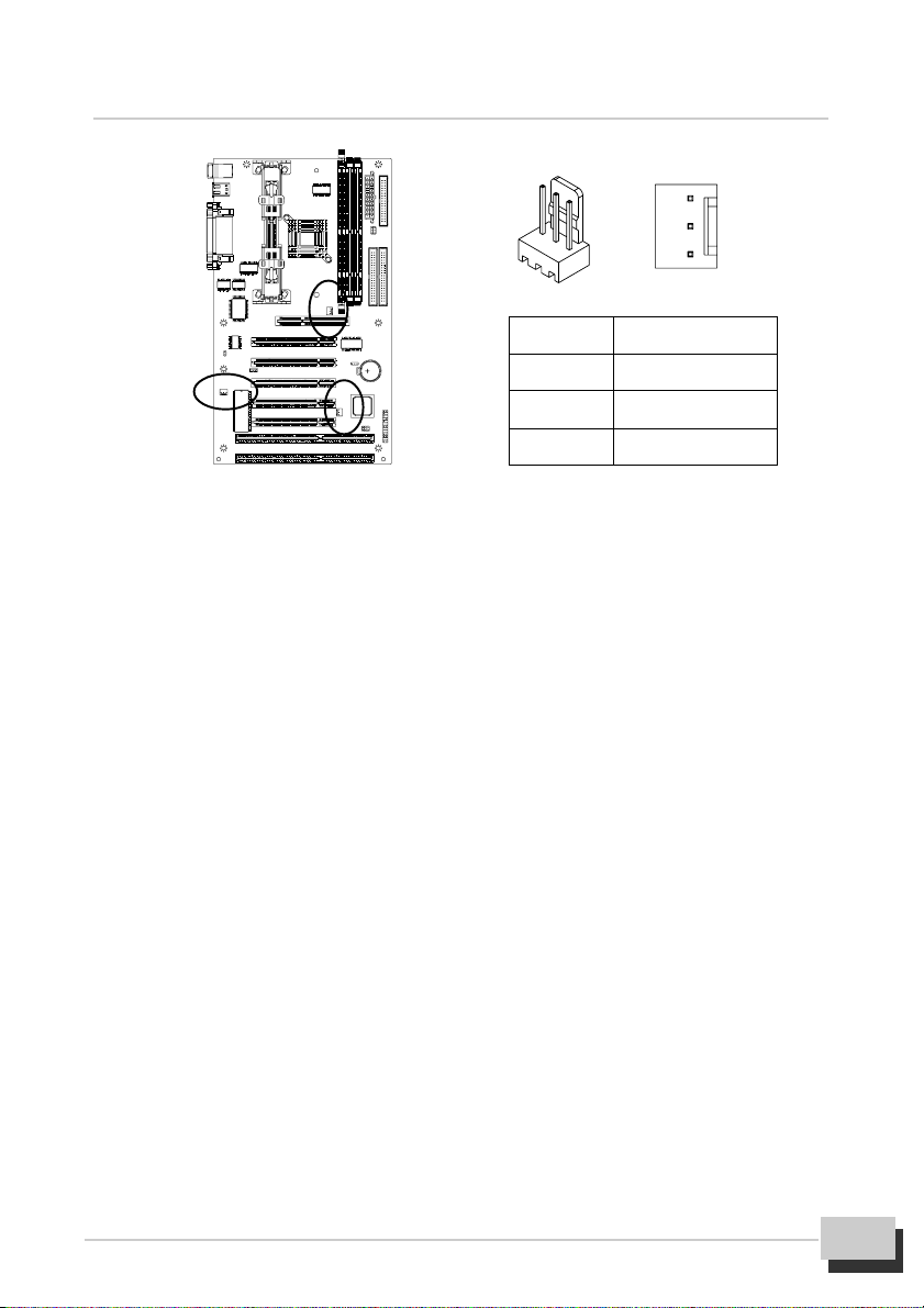
zz
z CPU / CHASSIS FAN Connector “J6/8/9”
zz
z These are 3-Pin connector that support cooling fan of 12 VDC/0.5A or less,
when the system goes into sleep state, fan should be shut down to eliminate
audible noise and reduce power consumption. You can monitor the fan speed
by way of W83977EF chip and the fan must come with a tachometer output on
the J6 and J9.
z The CPU and motherboard will overheat if there is no air flow across the CPU
and onboard heat sink. Damage may occur to the motherboard and the CPU fan
if these pins are incorrectly used.
5. Hardware Installation
3
1
Pin Assignment
1 GND
2 +12V
3 Speed/RPM
zz
z Safe Mode Header “JP5”
zz
z Usually Slot1 processors have locked frequency multiples. In this case, there is
no way to exceed the specified multiple whether through motherboard setting or
BIOS setup. With unlocked Slot1 processors, exceeding the specified multiple
and FSB is possible through BIOS setup or hardware setting. Over clock may
caused system hang or fail to boot-up (no video). If this happens there is a
methods let your system enter safe mode and get your system back again.
z Method : The following instructions can be performed to safe mode setting.
z Power off the system, then place the jumper cap to short Pin 1-2 of JP5.
z When power on the system, the system will enter safe mode for reboot
your system.
z Then power off the system again, remove the jumper cap from Pin 1-2
and put the jumper cap back to Pin-1 of JP5. After that power on the
system again to check the setting.
MVBX2-X User’s Manual
13

Jumper Cap Function
Short Pin 1-2 Safe Mode
Open Pin 1-2 Normal Operation
Step2: Install the Slot1 Processor
z This motherboard supports a wide range of Intel Slot1 processor include the SEPP
(Single Edge Processor Package) Celeron, the Pentium II and the Pentium III.
z The SEPP Celeron uses a Pentium II processor with 32K of internal level 1 cache
memory and 128K of external level 2 cache memory. Clock speed run from
266MHz through to 433MHz. They operate over a 66MHz system bus.
z The Pentium II processor is supported with 32K of internal level 1 cache memory
and 512K of external level 2 cache memory. Clock speed run from 233MHz
through to 450MHz. All but the slowest Pentium II’s operate over a 100MHz
system bus.
z The Pentium III processor is identical to the Pentium II processor except that it has
added instructions that are designed to improve performance in areas such as
the internet, encoding and decoding of compressed audio and video files and
soon. Currently, the Pentium III processor ships with clock speeds of
450MHz, 500MHz, 550MHz, 600MHz, and 667MHz. Pentium III’s operate
over a 100/133MHz system bus.
z The MVBX2-X motherboard provides a Universal Retention Module for Pentium
II/III and Celeron processor in SECC, SECC2 and SEPP. Please check URM
well setup on the motherboard already.
z Follow the steps mentioned below to install the Slot1 processor :
z Before the processor install, you have to make sure that the EAR of the
URM open already.
2
1
14
MVBX2-X User’s Manual

5. Hardware Installation
z Remove the sliders (both) of the URM to “OPEN” position.
z Orient the Slot1 processor and insert vertically on to the slot until the processor
clip into place.
z Remove the sliders of the URM to “LOCK” position.
LOCK
SLIDER
OPEN
z Locate the fan power connector J6 for the processor cooling fan, then connect
the cable from cooling fan to J6.
Warning : Processor require a heat sink with a cooling fan. Failure to provide
adequate cooling of the processor may seriously affect system performance or
cause permanent damage to the processor.
z If you need to remove the processor from the motherboard, the procedure will be
as follows.
z Disconnect the fan power cable from the motherboard.
z Remove the sliders of the URM to “OPEN” position.
MVBX2-X User’s Manual
15

z Push the latches on the processor toward the center of the processor
until they click into place (This step for Intel cartridge type processor only).
z Lift one end of the processor until it is freed from Slot1. Lift the other end of the
processor until it is freed from the Slot1. Lift the entire processor until it is free
from the URM.
Step3: Install the SDRAM Modules
z The motherboard has three DIMM (Dual In-line Memory Module) sockets which
support SDRAM modules installed with 3.3V, unbuffered, PC-100 (100MHz) and
PC-133 (133MHz) SDRAM memory chips. Each memory module can support a
maximum capacity of 128MB so total maximum memory is 384MB.
z Follow the steps mentioned below to install the SDRAM module :
z On the motherboard, locate the three DIMM sockets.
z Pull the locking latches of the DIMM sockets outwards.
z Align the memory module correctly. The edge connector of the memory module
has notches that match obstructions in the DIMM socket. You must match the
notches with the obstructions in order to install the module.
z Press the edge connector of the memory module into the DIMM socket. Press
down quite firmly so that the locking latches of the DIMM socket are levered
upwards to secure the memory module in place.
z Repeat the process with any other memory modules that you want to install.
16
MVBX2-X User’s Manual

5. Hardware Installation
5.4 Install the motherboard in a chassis
After you have prepared the motherboard by installing a processor, one or more memory
modules and have set the jumpers correctly, install the motherboard into a chassis and
begin connecting essential peripheral items to the connectors on the motherboard.
Follow the instructions given with the chassis to install the motherboard into the mounting
brackets inside the chassis. The motherboard has several holes drilled through it and you
should be able to drive a screw through some of these holes into the mounting brackets in the
chassis. Don’t overtighten the screws as this can stress the motherboard.
Note: Make sure that the power supply unit in the chassis is not connected to a power outlet
while you are carrying out the installation procedure.
We will begin the installation of the motherboard. Please follow the procedure step by step
which designed to guide you to a complete and correct installation.
Step1: Install the Expansion Card
zz
z This motherboard has five PCI, two ISA and an AGP slots. You can use the expansion
zz
slots to install expansions card that add new feature to your system.
z The AGP slot supports an add-on graphics adapter which has an AGP
(Accelerated Graphics Port) edge slot.
z The ISA slots support legacy add-on cards which have an 8/16 bit ISA (Industry
Standard Architecture) edge slot.
z The PCI slots support current add-on cards which have a 32 bit PCI (Peripheral
Components Interconnect) edge slot.
zz
z You must install a graphics adapter in order to use the system. For best performance,
zz
we recommend you to use an AGP adapter. You do not need to use an AGP
adapter. You can also install a graphics adapter in a PCI slot.
zz
z Follow the steps mentioned below to install the Expansion card :
zz
z Locate the expansion slots on the motherboard. Select which slot you plan to use
according to the kind of add-on card you are going to install.
z In the chassis, remove the blanking plate from the opening in the chassis adjacent
to the slot you are going to use.
z Hold the edge connector of the add-on card directly over the slot that you are
going to use. The metal bracket on one edge of the add-on card fits into the
opening from which you removed the blanking plate.
MVBX2-X User’s Manual
17
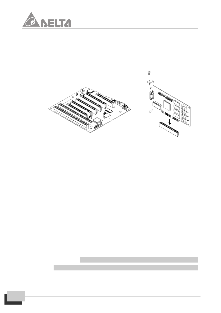
z Carefully press the card down so that the edge connector installs into the
expansion slot. You might need to rock the card slightly to make sure that
the edge connector is seated properly into the slot.
z Drive a screw through the metal bracket on the edge of the card to secure it in
place.
Step2: Install the IDE Device
z The motherboard has two IDE channel ports, the Primary IDE channel and
Secondary IDE channel. Each IDE channel can support two IDE devices. IDE
devices include hard disk drives, CD-ROM drives and removable media drives
such as ZIP drives and LS-120 drives.
Typically, most people install one IDE hard disk drive and one IDE CD-ROM drive
so this motherboard ships with one IDE cable. You can easily obtain a second IDE
cable if you want to install more than two IDE devices.
z Follow the steps mentioned below to install the IDE device :
z Locate the IDE1 and IDE2 box header on the motherboard.
z IDE1-Connect one end of the 40-Pin ribbon cable that comes with the drive to the
HDD header, and the other end of the cable to the IDE1 box header on the
motherboard.
z IDE2-Connect one end of the 40-Pin ribbon cable that comes with the drive to the
CD-ROM header, and the other end of the cable to the IDE2 box header on the
motherboard. (Note : Each header has the Pin-1 side clearly marked. The Pin-
1 side of the each ribbon cable is always marked with a red stripe on the cable.)
18
MVBX2-X User’s Manual

Rear of IDE Device
5. Hardware Installation
Master
Slave
Master
Slave
IDE2
Red Stripe
Pin -1
z The primary channel has priority to the secondary channel. Within each channel,
IDE1/2
the two different devices are distinguished by master and slave relationship. The
master device has priority over the slave device. (Refer to illustration on the below)
Primary IDE1 Secondary IDE2
Status 1
Status 2
Status 3
Master Slave
HDD
C:
HDD
C:
HDD
C:
HDD
D:
CD
E:
Master Slave
HDD
D:
HDD
E:
CD
F:
HDD
F:
HDD
D:
Primary Channel has
priority over the
Secondary Channel
Master has priority
over the Slave
Devices
Hard Disk Drives have
priority over the CDROM Devices
Note : Ultra DMA66 IDE devices must use an 80-Pin IDE cable.
Step3: Install the FDD Device
z The motherboard has a floppy disk drive interface that will support one or two floppy
disk drives. The floppy disk drive ribbon cable has connectors for two 3.5”
wide disk drives.
MVBX2-X User’s Manual
19

z Follow the steps mentioned below to install the FDD device :
z Locate the FDC1 box header on the motherboard.
z FDC1-Connect one end of the 34-Pin ribbon cable that come with the drive to the
FDD header, and the other end of the cable to the FDC1 box header on the
motherboard. (Note: Each header has the Pin-1 side clearly marked. The Pin-1
side of the each ribbon cable is always marked with a red stripe on the cable.)
Rear of Floppy
Disk Drive
Master
Slave
Red Stripe
Pin-1
FDC1
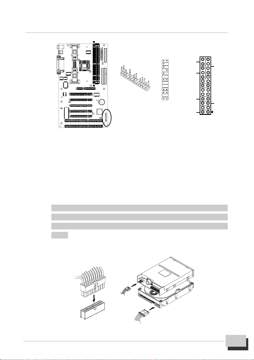
Step4: Front Panel I/O Connections
This motherboard connects to the front panel I/O are located on jumper block J2.
Follow the instruction carefully for proper connections to your front panel display
and control. This section explains how to connect these components.
zz
z PW-SW : It is a 2-Pin header connects to the chassis-mounted power button.
zz
zz
z RST-SW : It is a 2-Pin header connects to the chassis-mounted reset switch and is
zz
used to reboot the system.
z HD-LED : It is a 2-Pin header connects to the chassis-mounted HDD LED to
indicate HDD activity.
z SPEAKER : It is a 4-Pin header connects to the chassis-mounted speaker. When
system has any abnormally state that you will hear warnings through speaker.
z PW-LED : It is a 3-Pin header connects to the chassis-mounted power LED to
indicate onboard power state.
z KB-LK : It is a 2-Pin header connects to the chassis-mounted key lock switch that is
used to lock the keyboard for security purpose.
20
MVBX2-X User’s Manual
5. Hardware Installation
26 25
KB-LK
PW-LED
HD-LED
2 1
PW-SW
Step5: ATX1 / HDD / FDD Power Connection
z Connect ATXPWR of the power supply unit to the ATX1 connector on the motherboard.
z Connect HDDPWR of the power supply unit to the power connector on the HDD
device.
z Connect FDDPWR of the power supply unit to the power connector of the
FDD device.
Note : Incorrect installation of the power supply could result in serious damage
to the motherboard and connected peripherals. Make sure the power supply
is unplugged from the AC outlet before connecting the leads from the power
supply.
26 25
+
+
2 1
SPEAKER
+
RST-SW
MVBX2-X User’s Manual
21

Step6: Back I/O Connections
The back panel provides external access to PS/2 style Keyboard and Mouse
Port, two Serial Ports, two USB Ports, a Parallel Port, which are integrated on the
motherboard PC99 compliant. Follow the instruction carefully for proper con-
nection I/O peripherals to your system.
zz
z K/B & MS is a stack of the two PS/2 mini DIN ports.
zz
z K/B & MS (Green 6-Pin Mouse Port) can be used by a PS/2 Mouse or pointing
device.
z K/B & MS (Purple 6-Pin Keyboard Port) can be used by a PS/2 Keyboard.
zz
z USB1 (Black two 4-Pin USB Ports) is available for connecting USB devices.
zz
zz
z LPT1 (Burgundy 25-Pin Parallel Port) can be used by Printers or other Paral-
zz
lel communication devices.
zz
z COM1, 2 (Teal/Turquoise two 9-Pin Serial Ports) is ready for a Mouse or
zz
other Serial devices.
USB1 (Black) LPT1 (Burgundy)
K/B & MS
(Green)
K/B & MS
(Purple)
Step7: Boot the System
This chapter is a step by step guide that explains how to use your MVBX2-X motherboard
to build a powerful system. At a minimum, you will need the following components in
order to build a fully function system.
z After hardware configuration of motherboard is completed and system hardware
22
MVBX2-X User’s Manual
COM1 COM2
(Teal/Turguoise)
has been assembled. Refer to combination as follows.

5. Hardware Installation
z You are now ready to boot the system for the first time. Please continue to the next
section to configure your BIOS (Basic Input Output System) setting. It must be
configured after booting.
MVBX2-X User’s Manual
23

6. BIOS Configuration
When you start the computer, it is controlled by the BIOS program. The BIOS first operates
an auto-diagnostic for all the necessary hardware, configures the parameters of the hard-
ware synchronization, and detects all the hardware. Only when these tasks are completed
does it give up control of the computer to program in the next level, which is the operating
system. Since the BIOS is the only channel for hardware and software to communicate, it is
the key factor for system stability, and the assurance to your system good performance.
After the BIOS has achieved the auto-diagnostic and auto-detection operations, pressing
the Del key will allow you to access the BIOS Setup menu. At that point, the BIOS will display
the following message.
Standard CMOS Setup
This “Standard CMOS Setup” option allows you to record some basic configuration of the
system hardware, setting of system clock and error handling. If the motherboard is already
installed in a working system, there is no need to select this option. However, if the configu-
ration stored in the CMOS memory on the board get lost or damaged, or if you change
your system hardware configuration, you will need to reset the configuration values. The
configuration values usually get lost or corrupted when the power of onboard CMOS battery
weakens.
The preceding screen provides you with a list of options. At the bottom of this scrare the
control keys for this screen. Take note of these keys and their respective uses.
24
MVBX2-X User’s Manual

6. BIOS Configuration
User-configurable fields appear in a different color. If you need information on the
selected field, press <F1>. The help menu will then appear to provide you with the
information you need. The memory display at the lower right-hand side of the screen is
read-only and automatically adjusts accordingly.
Date
To set the date, highlight the “Date” field and then press either <Page Up> / <Page Down> or
<+>/<-> to set the current date. Follow the month, day and year format. Valid values for
month, day and year are: Month: (1 to 12), Day: (1 to 31), Year: (up to 2079).
Time
To set the time, highlight the “Time” field and then press either <Page Up>/<Page Down> or
<+>/<-> to set the current time. Follow the hour, minute and second format. Valid values for
hour, minute and second are: (Hour: (00 to 23), Minute: (00 to 59), Second: (00 to 59).
Press <Enter> twice if you do not want to modify the current time.
Hard Disks
This field records the specifications for all non-SCSI hard disk drives installed in your system.
The onboard PCI IDE connectors provide Primary and Secondary channels for connecting
up to four IDE hard disks or other IDE devices. Each channel can support up to 2 hard
disks; the first of which is the “master” and the second is the “slave”.
For IDE hard disk drive setup, you can:
z Use the Auto setting for detection during bootup.
z Use the IDE HDD AUTO DETECTION in the main menu to automatically enter the
MVBX2-X User’s Manual
25

drive specifications.
z Enter the specifications yourself manually by using the “User” option.
The entries for specifying the hard disk type include CYLS (number of cylinders), HEAD
(number of read/write heads), PRECOMP (write precompensation), LANDZ (landing zone),
SECTOR (number of sectors) and MODE. The SIZE field automatically adjusts according
to the configuration you specify. The documentation that comes with your hard disk should
provide you with the information regarding the drive specifications.
The MODE entry is for IDE hard disks only, and can be ignored for MFM and ESDI drives.
This entry provides three options: Normal, Large, LBA, or Auto (see below). Set MODE to
the Normal for IDE hard disk drives smaller than 528MB; set it to LBA for drivers over
528MB that support Logical Block Addressing (LBA) to allow larger IDE hard disks; set it to
Large for drives over 528MB that do not support LBA. Large type of drive can only be used
with MS-DOS and is very uncommon. Most IDE drives over 528MB support the LBA mode.
Auto detection of hard disks on bootup
For each field: Primary Master, Primary Slave, Secondary Master, and Secondary Slave,
you can select Auto under the TYPE and MODE fields. This will enable auto detection of
your IDE hard disk during bootup. This will allow you to change your hard disks (with the
power off) and then power on without having to reconfigure your hard disk type. If you use
older hard disks that do not support this feature, then you must configure the hard disk in
the standard method as described earlier by the “User” option.
Drive A / Drive B
These fields record the types of floppy disk drives installed in your system. The available
options for drives A and B are: 360KB, 5.25in; 1.2MB, 5.25in; 720KB, 3.5in.; 1.44MB, 3.5
in; 2.88MB, 3.5 in; None.
To enter the configuration value for a particular drive, highlight its corresponding field and
then select the drive type using the left- or right-arrow keys.
Video
Set this field to the type of video display card installed in your system. The options are EGA/
VGA, CGA 49, CGA 80, and Mono (for Hercules or MDA).
If you are using a VGA or any higher resolution card, choose EGA/VGA.
Halt On
This field determines which types of errors will cause the system to halt. Choose from All
Errors; No Errors; All, But Keyboard, All, But Diskette; and All, But Disk/Key.
26
MVBX2-X User’s Manual

6. BIOS Configuration
BIOS Features Setup
This “BIOS Features Setup” option consists of configuration entries that allow you to im-
prove your system performance, or let you set up some system features according to your
preference. Some entries are required by the motherboard’s design to remain in their
default settings details.
A section at the lower right of the screen displays the control keys you can use. Take note of
these keys and their respective uses. If you need information on a particular entry, highlight
it and then press <F1>. A pop-up help menu will appear to provide you with the information
you need. <F5> loads the last set values while, <F6> and <F7> loads the BIOS default
values and Setup default values, respectively.
Virus Warning
When this feature is enabled, if there is any attempt from a software or an application to
access the boot sector or the partition table, the BIOS will warn you that a boot virus is
attempting to access to the hard disk.
CPU Card L1 Cache / CPU Card L2 Cache
These fields allow you to choose from the default of Enabled or choose Disabled to turn on
or off the CPU’s Level 1 and Level 2 built-in cache.
CPU L2 Cache ECC Checking
Enabled this function to perform ECC (Error Check and Correct) on the CPU’s L2 SRAM.
Processor Number Feature
MVBX2-X User’s Manual
27

The Pentium III processors are installed with a unique processor identification number. If
you Disabled this item, the number will be suppressed to that it cannot be read by other
systems on the network.
Quick Power On Self Test
This will skip some diagnostic checks during the Power On Self Test (POST) to speed up
the booting process.
Boot Sequence
This field determines where the system looks first for an operating system. Options are “A,
C,SCSI”, “C,A,SCSI”, “C,CDROM,A”, “CDROM,C,A”, “D,A,SCSI”, “E,A,SCSI”, “F,A,SCSI”, “SCSI,
A,C”, “SCSI,C,A”, “C only” and “LS/ZIP,C”; The setup default setting is to check first the floppy
diskette and then the hard disk drive.
Swap Floppy Drive
When enabled, exchange of logical drive will occur the floppy drive A will be changed to B
without changing the physical cable.
Boot Up Floppy Seek
When enabled, the BIOS will seek drive A once.
Boot Up NumLock Status
This field enables users to activate the Number Lock function upon system boot.
IDE HDD Block Mode
This feature enhances disk performance by allowing multisector data transfers and
eliminates the interrupt handling time for each sector. Most IDE drives, except with old
designs can support this feature.
Gate A20 Option
This field uses the fast gate A20 line to access any memory above 1MB. Setting this item
to make the access faster than the normal method.
Memory Parity/ECC Check
This item allows you to select between three methods of memory error checking, Auto,
Enabled and Disabled.
Typematic Rate Setting
When enabled, you can set the two typematic controls listed next.
Typematic Rate (Chars/Sec)
This field controls the speed at which the system registers repeated keystrokes. Options
28
MVBX2-X User’s Manual

6. BIOS Configuration
range from 6 to 30 characters per second. Setup default setting is 6, other settings are 8,
10, 12, 15, 20, 24, and 30.
Typematic Delay (Msec)
This field sets the time interval for displaying the first and second characters Four delay
rate options are available: 250, 500, 750, and 1000.
Security Option
When you specify a Supervisor Password and/or User Password (explained later in this
section), the Security Option field determines when the system prompts for the password.
The default setting is Setup, where the system goes through its start-up routine unless the
Setup utility is called, then the system prompts for the Supervisor Password. The other
option is System, where the system prompts for the User Password every time you start
your system.
PCI/VGA Palette Snoop
It determines whether the MPEG ISA/PCI VGA Cards can work with PCI/VGA or not.
OS Select For DRAM > 64MB
When using OS/2 operating systems with installed DRAM of greater than 64MB, you need
to set this option to Enabled otherwise leave this on Disabled.
Report No FDD For WIN 95/98
Windows will release IRQ line 6 (normally used by the Floppy Disk Drive) after you disable
your onboard FDD and set this field to “YES”. If you set this field to “NO”, the windows will
reserve INT6 for your FDD.
Video BIOS Shadow
This field allows you to change the video BIOS location from ROM to RAM. Relocating to
RAM enhances system performance, as information access is faster than the ROM.
C8000-CBFFF to DC000-DFFFF
These fields are used for shadowing other expansion card ROMs. If you install other ex-
pansion cards with ROMs on them, you will need to know which addresses the ROMs use
to shadow them specifically. Shadowing a ROM reduces the memory available between
640K and 1024K by the amount used for this purpose.
MVBX2-X User’s Manual
29
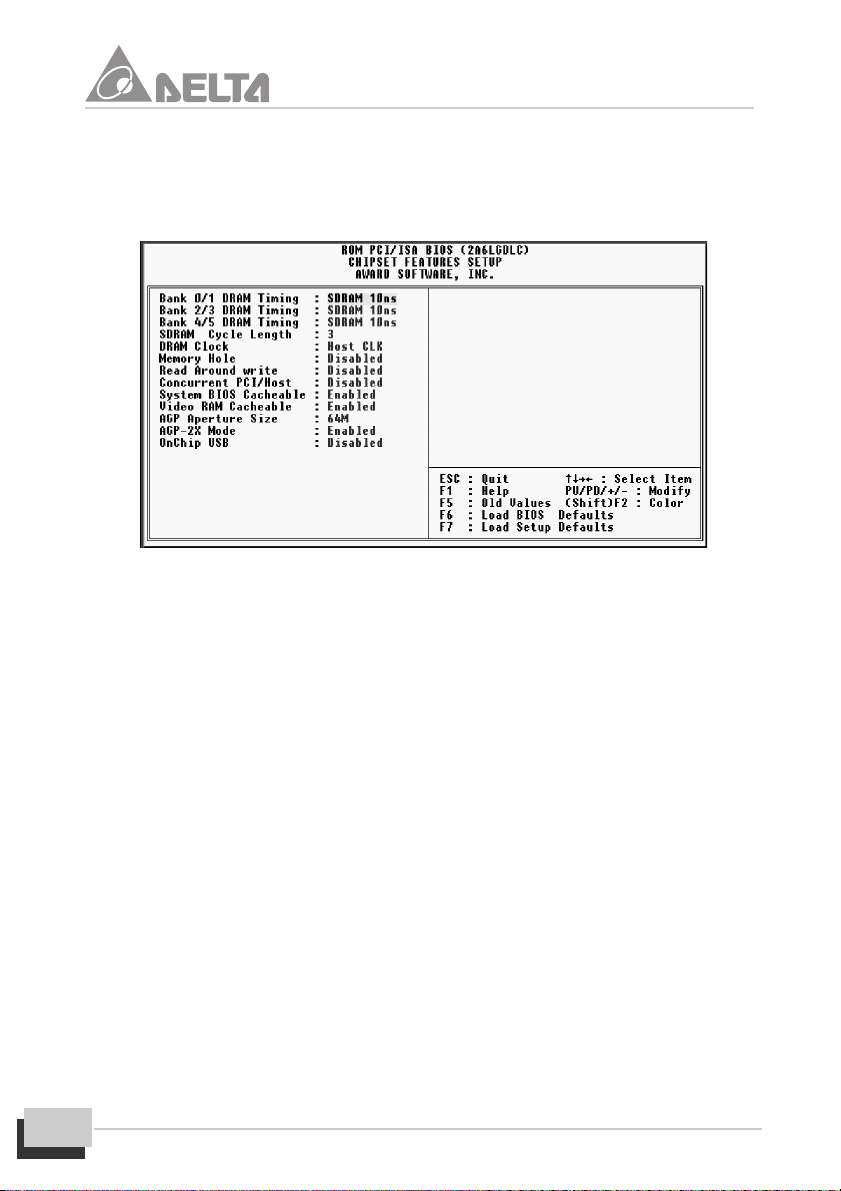
Chipset Features Setup
This “Chipset Features Setup” option controls the configuration of the board’s chipset.
Control keys for this screen are the same as for the previous screen.
Bank 0/1, 2/3, 4/5 DRAM Timing
This field allows you to set the Timing of Bank 0/1, 2/3, 4/5.
SDRAM Cycle Length
This field allows you to set the CAS latency timing to 2 or 3.
DRAM Clock
This field allows you to set DRAM Clock.
Memory Hole
In order to improve performance, certain space in memory can be reserved for ISA
cards. This memory must be mapped into the memory space below 16MB.
Read Around write
This field sets the DRAM optimization feature. If a memory read is a addressed to a
location whose latest write is being held in a buffer before being written to memory, the
read is satisfied through the buffer contents, and the read is not sent to the DRAM.
Concurrent PCI/Host
When disable, CPU bus will be occupied during the entire PCI operation period.
System BIOS Cacheable
This field allows you to cache the System BIOS for higher performance.
30
MVBX2-X User’s Manual

6. BIOS Configuration
Video RAM Cacheable
This field allows you to cache the Video RAM for higher performance.
AGP Aperture Size
Select the size of the Accelerated Graphics Port (AGP) aperture. The aperture is a
portion of the PCI memory address range dedicated for graphics memory address
space. Host cycles that hit the aperture range are forwarded to the AGP without any
translation.
AGP-2X Mode
If you have AGP Card, Please set it to Enabled.
OnChip USB
This should be enabled if your system has a USB installed on the system board and you
wish to use it. Even when so equipped, if you add a higher performance controller, you
will need to disable this feature.
MVBX2-X User’s Manual
31

Power Management Setup
This “Power Management Setup” option allows you to reduce power consumption. This
feature turns off the video display and shuts down the hard disk after a period of inactivity.
ACPI Function
Leave setting it on default.
Power Management
This field acts as the master control for the power management modes. Max. Saving puts
the system into power saving mode after a brief period of system inactivity. Min. Saving is
almost the same as Max. Saving except that this time the system inactivity period takes
longer. Disable disables the power saving features while User Define allows you to set
power saving options according to your preference.
IMPORTANT: Advanced Power Management (APM) should be installed to keep the sys-
tem time updated when the computer enters suspend mode activated by the BIOS Power
Management. For DOS environments, you need to add the statement, DEVICE=C:
\DOS\POWER.EXE, in you CONFIG.SYS. For Windows 3.x and Windows 95, you need to
install Windows with the APM feature. A battery and power cord icon labeled “Power” will
appear in the “Control Panel”. Choose “Advanced” in the Power Management Field.
PM Control by APM
Power Management is completely controlled by the APM. APM stands for Advanced Power
Management, it is a power management standard set by Microsoft, Intel and other major
manufacturers.
32
MVBX2-X User’s Manual

6. BIOS Configuration
Video Off After
This field determines when to activate the video off feature for monitor power management.
The settings are NA, Suspend, Stand by.
Video Off Method
This field defines the video off features. The following options are available: DPMS OFF,
DPMS Reduce ON, Blank Screen, V/H SYNC + Blank, DPMS Standby, and DPMS Suspend.
The DPMS (Display Power Management System) features allow the BIOS to control the
video display card if it supports the DPMS feature. Blank Screen only blanks the screen
(use this for monitors without power management or “green” features. If Blank screen is set
up in your system, your screen saver will not display). V/H SYNC + Blank will blanks the
screen and turns off vertical and horizontal scanning.
MODEM Use IRQ
This field allows you to assign IRQ to external modem that is to be connected to the system.
Soft-Off by PWR-BTTN
This field allows you to set Power off mode through Instant-Off or Delay mode (4 sec.) When
you select Instant-Off mode to turn off the system, just press the power button and the
system will Power off immediately, If you select Delay mode, you must press the power
button for at least 4 seconds in order to turn off the system.
PM Timers
The following four modes are Green PC power saving functions which are only user
configurable when User Defined Power Management has been selected. See above for
available selections.
Normal Doze Standby Suspend
Power Saving Mode Flow Chart
HDD Power Down
Shuts down any IDE hard disk drives in the system after a period of inactivity. The time
period is user-configurable with select from 1-15 Min. It also contains a Disabled option and
does not affect SCSI hard drives.
VGA
When set to OFF, any event occurring at a VGA port will awaken a system which has been
powered down.
MVBX2-X User’s Manual
33

LPT & COM
When set to LPT/COM, any event occurring at a COM(serial)/LPT (printer) port will awaken
a system which has been powered down.
HDD & FDD
When set to On, any event occurring at a hard or floppy drive port will awaken a system
which has been powered down.
DMA/master
When set to ON, any event occurring at a hard or floppy drive port will awaken a system
which has been powered down.
Modem Ring Resume
If a modem is connected to the system, this feature allows an incoming call to power up the
system in soft-off mode.
Wake Up on LAN
This allows the selection of either Enabled or Disabled setting to power up the computer
(make sure system power is on) when the LAN Card receives a call while the computer is
off.
RTC Alarm Resume
This motherboard an alarm on the system real-time clock that can resume the system
from a software powerdown or a power-saving mode. Use this item to enable or disable this
feature.
Primary INTR
When set to ON, any event occurring at will awaken a system which has been powered
down.
IRQ3 ~ IRQ15
The IRQ3 ~ IRQ15 is a list of IRQ’s (Interrupt Requests), which can be exempted much as
the COMS ports and LPT port above can. When an I/O device wants to gain the attention of
the operation system, it signals this by causing an IRQ to occur. When the operating system
is ready to respond to the request, it interrupts itself and performs the service.
34
MVBX2-X User’s Manual
6. BIOS Configuration
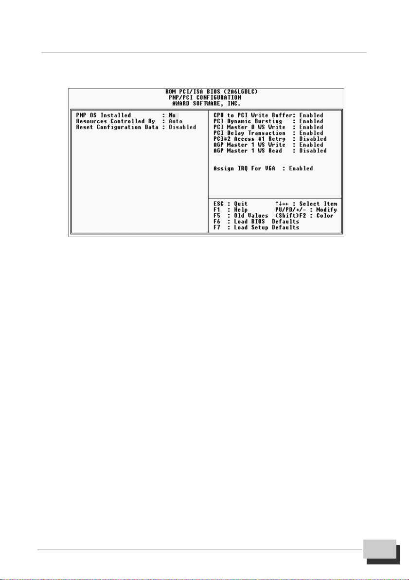
PNP and PCI Setup
This “PNP and PCI Setup” option configures the PCI bus slots. All PCI bus slots on the
system use INTA#, thus all installed PCI cards must be set to this value.
PNP OS Installed
This field allows you to use a Plug-and Play (PnP) operation system to configure the PCI
bus slots instead of using the BIOS. Therefore, interrupts may be reassigned by the OS
when Yes is selected. When a non-PnP OS is installed or to prevent reassigning of interrupt
settings, select the default setting of No.
Resources Controlled By
These fields set how IRQ use is determined for each PCI slot. The default setting for each
field is Auto, which uses auto-routing to determine IRQ use. The other options are manual
settings of NA, 5, 7, 9, 10, 11, 12, 14 or 15 for each slot.
Reset Configuration Data
When Enabled the system BIOS will clear/reset the ESCD during POST. After clearing the
ESCD, the BIOS will then change this item’s value to “Disabled”. Otherwise, the ESCD data
would become useless.
When enabled, up to four Dwords of data can be written to the PCI bus without interrupting
the CPU. When disabled, a write buffer is not used and the CPU read cycle will not be
completed until the PCI bus signals that it is ready to receive the data.
CPU to PCI Write Buffer
When enabled, up to four Dwords of data can be written to the PCI bus without interrupting
MVBX2-X User’s Manual
35

the CPU. When disabled, a write buffer is not used and the CPU read cycle will not be
completed until the PCI bus signals that it is ready to receive the data.
PCI Dynamic Bursting
When Enabled, every write transaction goes to the write buffer. Burstable trans-actions
then burst on the PCI bus and nonburstable transactions don’t.
PCI Master 0 WS Write
When Enabled, writes to the PCI bus are executed with zero wait states.
PCI Delay Transaction
The chipset has an embedded 32-bit posted write buffer to support delay transactions
cycles. Select Enabled to support compliance with PCI specification version 2.1.
PCI#2 Access #1 Retry
This item allows you Enable or Disable the PCI#2 Access #1 Retry.
AGP Master 1 WS Write
This implements a single delay when writing to the AGP Bus. By default, two-wait states
are used by the system, allowing for greater stability.
AGP Master 1 WS Read
This implements a single delay when reading to the AGP Bus. By default, two-wait states
are used by the system, allowing for greater stability.
Assign IRQ For Assign IRQ For VGA
Name the interrupt request (IRQ) line assigned to the /VGA on your system. Activity of the
selected IRQ always awakens the system.
36
MVBX2-X User’s Manual

6. BIOS Configuration
Load BIOS Defaults
This “Load BIOS Defaults” option allows you to load the troubleshooting default values
permanently stored in the BIOS ROM. These default settings are non-optimal and disable
all high performance features. To load these default settings, highlight “Load BIOS Defaults”
on the main screen and then press <Enter>. The system displays a confirmation message
on the screen. Press <Y> and then <Enter> to confirm. Press <N> and then <Enter> to
abort. This feature does not affect the fields on the Standard CMOS Setup screen.
Load Setup Defaults
This “Load Setup Defaults” option allows you to load the default values to the system
configuration fields. These default values are the optimized configuration settings for the
system. To load these default values, highlight “Load Setup Defaults” on the main screen
and then press <Enter>. The system displays a confirmation message on the screen.
Press <Y> and then <Enter> to confirm. Press <N> and then <Enter> to abort. This
feature does not affect the fields on the Standard CMOS Setup screen.
MVBX2-X User’s Manual
37

CPU Features Setup
This “CPU Features Setup” let you install hardware monitoring parameters so that the
system can warn you when critical parameters are exceeded.
CPU Ration
Use this item to select a multiplier for the system front side bus frequency. The value of the
multiplier must be set so that :
Multiplier x Front Side Bus Frequency = CPU Clock Speed
For example, if you have a processor that is rated to run at 450MHz and the system is
running a front side bus frequency of 100MHz, you should select a multiplier of 4.5 so that
4.5 (Multiplier) x 100MHz (Front Side Bus) = 450MHz (CPU Clock)
Auto Detect DIMM / PCI Clk
If you enable this item, the system does not generate clock signals for unused PCI or DIMM
slots, so that EMI (electromagnetic interference) is reduced.
CPU Clock / Spread Spectrum
If you enable spread spectrum, the EMI generated by the system is greatly reduced.
CPU Warning Temperature
If you have installed hardware monitoring you can enable this item so that the system
gives a warning beep when critical CPU temperatures are exceeded.
38
MVBX2-X User’s Manual

6. BIOS Configuration
Integrated Peripherals
On-Chip Primary/Secondary PCI IDE
You can select to enable the primary IDE channel, secondary IDE channel, both, or disable
both channels.
Primary Master/Slave PIO/UDMA Mode, Secondary Master/Slave PIO/UDMA Mode
Each channel (0 & 1) has both a master and a slave making four IDE devices possible.
Because each IDE device may have a different PIO Mode timing of 0, 1, 2, 3, or 4, it is
necessary for these to be independent. DMA Mode timing allows 0, 1, or 2. The default
setting of Auto will allow auto-detection to ensure optimal performance.
IDE Prefetch Mode
The onboard IDE drive interfaces supports IDE prefetching for faster drive accesses. If you
install a primary and / or second IDE interface. Select Disabled to deactivate an interface, if
you install a primary and / or secondary add-in IDE interface.
Init Display First
This item allows you to decide to active PCI or AGP Slot first.
POWER ON Function
This field allows you to set POWER ON mode from button only, Hot-Key, PS/2 Mouse
password or keyboard 98 mode.
KBC input clock
This item sets the clock speed for the keyboard controller. Leave this item at the default
value of 8MHz.
MVBX2-X User’s Manual
39

Onboard FDC Controller
When Enabled, this field allows you to connect your floppy disk drives to the onboard floppy
disk drive connector instead of a separate controller card. If you want to use a different
controller card to connect the floppy disk drives, set this field to Disabled.
Onboard Serial Port 1
Settings are 3F8H/IRQ4, 2F8H/IRQ3, 3E8H/IRQ4, 2E8H/IRQ 3, Auto and Disabled for the
onboard serial connector.
Onboard Serial Port 2
Settings are 3F8H/IRQ4, 2F8H/IRQ3, 3E8H/IRQ4, 2E8H/IRQ3, Auto and Disabled for the
onboard serial connector.
UART2 Mode Select
This item allows you to determine which Infra Red (IR) function of onboard I/O chip.
Onboard Parallel Port
This field sets the address of the onboard parallel port connector. You can select either:
3BCH/IRQ 7, 378H/IRQ 7, 278H/IRQ 5, Disabled. If you install an I/O card with a parallel
port, ensure that there is no conflict in the address assignments. The PC can support up to
three parallel ports as long as there are no conflicts for each port.
Parallel Port Mode
This field allows you to set the operation mode of the parallel port. The setting SPP,
allows normal-speed operation but in one direction only. EPP allows bidirectional parallel
port operation at maximum speed. ECP allows the parallel port to operate in bidirectional
mode and at a speed faster than the maximum data transfer rate. And ECP+EPP allows
normal speed operation in a two-way mode.
40
MVBX2-X User’s Manual

6. BIOS Configuration
Supervisor Password and User Password
These two options set the system passwords. “Supervisor Password” sets a password
that will be used to protect the system and the Setup utility while “User Password” sets a
password that will be used exclusively on the system. By default, the system comes without
any passwords. To specify a password, highlight the type you want and then press <Enter>.
A password prompt appears on the screen, take note that the password is case sensitive,
and can reach up to 8 alphanumeric characters long, type in your password and then
press <Enter>. The system confirms your password by asking you to type it again. After
setting a password, the screen automatically reverts to the main screen.
To implement password protection, specify into the “Security Option” field of the BIOS
Features Setup screen once the system prompt for password. If you want to disable
either password, press <Enter> instead of entering a new password when the “Enter
Password” prompt appears. A message confirms the password has been disabled.
MVBX2-X User’s Manual
41

IDE HDD Auto Detection
This “IDE HDD Auto Detection” option detects the parameters of an IDE hard disk drive,
and automatically enters them into the Standard CMOS Setup screen.
Up to four IDE drives can be detected, with parameters for each listed inside the box. To
accept the optimal entries, press <Y> or else select from the numbers displayed under the
OPTIONS field (2, 1, 3 in this case); to skip to the next drive, press <N>. If you accept the
values, the parameters will appear listed beside the drive letter on the screen. The process
then proceeds to the next drive letter. Pressing <N> to skip rather than to accept a set of
parameters causes the program to enter zeros after that drive letter.
Remember that if you are using another IDE controller that does not feature Enhanced IDE
support for four devices, you can only install two IDE hard disk drives. Your IDE controller
must support the Enhanced IDE features in order to use Drive E and Drive F. The onboard
PCI IDE controller supports Enhanced IDE, with two connectors for connecting up to four IDE
devices. IF you want to use another controller that supports four drives, you must disable
the onboard IDE controller in the Chipset Features Setup screen.
When auto-detection is completed, the program automatically enters all entries you ac-
cepted on the field for that drive in the Standard CMOS Setup screen. Skipped entries are
ignored and are not entered in the screen.
If you are auto-detecting a hard disk that supports the LBA mode, three lines will appear in
the parameter box. Choose the line that lists LBA for an LBA drive. Do not select Large or
Normal.
42
MVBX2-X User’s Manual
6. BIOS Configuration
The auto-detection feature can only detect one set of parameters for a particular IDE
hard drive. Some IDE drives can use more than one set. This is not a problem if the drive
is new and empty.
IMPORTANT: If your hard disk was already formatted on an older previous system, incor-
rect parameters may be detected. You will need to enter the correct parameters manually
or use low-level format if you do not need the data stored on the hard disk.
If the parameters listed differ from the ones used when the disk was formatted, the disk will
not be readable. If the auto-detected parameters do not match the ones that should be
used for your disk, do not accept them. Press <N> to reject the presented settings and enter
the correct ones manually from the Standard CMOS Setup screen.
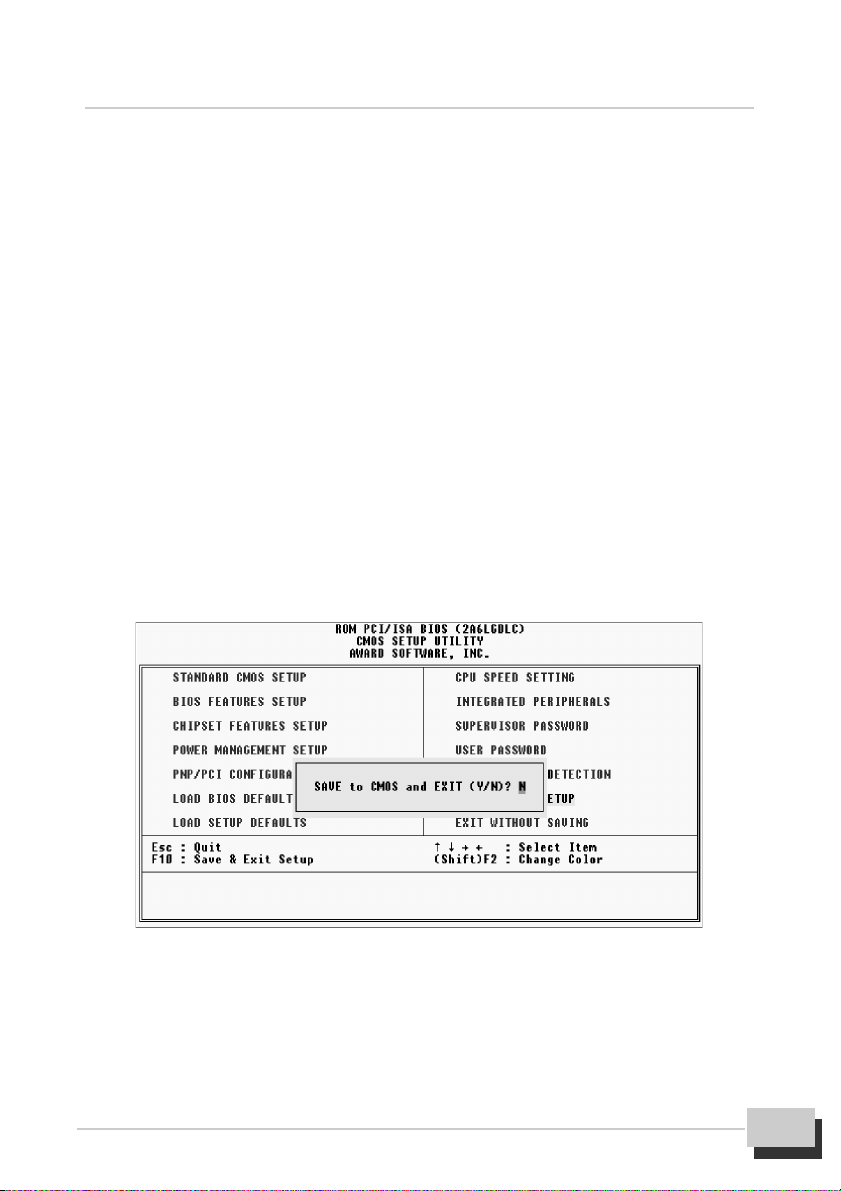
Save & Exit Setup
Select this option to save into the CMOS memory all modifications you specified during the
current session. To save the configuration changes, highlight the “Save & Exit Setup”
option on the main screen, type “Y”, and then press <Enter>.
Exit Without Saving
Select this option to exit the Setup utility without saving the modifications you specify
during the current session. To exit without saving, highlight the “Exit without Saving”
option on the main screen and then press <Enter>.
MVBX2-X User’s Manual
43
 Loading...