

Delta MultiChoice T27876, MultiChoice T27899, MultiChoice T27859, MultiChoice T27867, MultiChoice T27897 Installation Instructions Manual
...Page 1
MultiChoice® Valve Trim with Diverter
Installation Instructions
Owners Manual
T27859, T27867, T27876,
T27897, T27899, T27959,
T27967, T27976, T27997 &
T27999 Series
Write purchased model number here.
You May Need
THIS VALVE MEETS OR EXCEEDS THE
FOLLOWING STANDARDS: ASME A112.18.1/
CSA B125.1 and ASSE 1016 (Type -P- or -T-).
CAUTION: This system/device must be set by the
installer to ensure safe, maximum temperature.
Any change in the setting may raise the discharge
temperature above the limit considered safe and
may lead to hot water burns.
NOTICE TO INSTALLER: CAUTION!–As the
installer of this valve, it is your responsibility
to properly INSTALL and ADJUST this valve
per the instructions given. This valve does
not automatically adjust for inlet temperature
changes, therefore, someone must make the
necessary Rotational Limit Stop adjustments
at the time of installation and further adjustments
may be necessary due to seasonal water
temperature change. YOU MUST inform the
owner/user of this requirement by following
the instructions. If you or the owner/user are
unsure how to properly make these adjustments
please refer to page 6 and if still uncertain, call
us at 1-800-345-DELTA.
After installation and adjustment, you must afx
your name, company name and the date you
adjusted the Rotational Limit Stop to the caution
label provided and apply or attach the label to
the back side of the closest cabinet door and the
warning label to the water heater. Leave this
Instruction Sheet for the owner’s/user’s
reference.
WARNING: This pressure balanced or
thermostatic bath valve is designed
to minimize the effects of outlet water
temperature changes due to inlet pressure
changes, commonly caused by dishwashers,
washing machines, toilets and the like. It may
not provide protection from hot water burns
when there is a failure of other temperature
controlling devices elsewhere in the
plumbing system, if the rotational limit stop
is not properly set or if the hot water
temperature is changed after the settings are
made or if the water inlet changes
due to seasonal changes.
WARNING: Do not install a shut-off device on
either outlet of this valve. When this type of
device shuts off the water ow, it can defeat
the ability of the valve to balance the hot and
cold water pressures.
Rev. A1
102018
Table of Contents:
Warranties ............................................................................... Page 2
Installation Instructions ........................................................... Pages 3 - 7
Clean and care......................................................................... Page 9
Maintenance ............................................................................ Page 9
Cartridge Summary Reference Sheet ..................................... Page 9
Classic Series Replacement Parts .......................................... Page 10-16
For additional replacement parts, visit www.deltafaucet.com
03/15/2018
3/32"
Page 2

102018 Rev. A
2
Parts and Finish
All parts (other than electronic parts and batteries) and finishes of this Delta
®
faucet are warranted to the original consumer purchaser to be free from
defects in material and workmanship for as long as the original consumer purchaser owns the home in which the faucet was first installed or, for com-
mercial users, for 5 years from the date of purchase.
Electronic Parts and Batteries (if applicable)
Electronic parts (other than batteries), if any, of this Delta
®
faucet are warranted to the original consumer purchaser to be free from defects in material
and workmanship for 5 years from the date of purchase or, for commercial users, for one year from the date of purchase. No warranty is provided on
batteries.
Delta Faucet Company will replace, FREE OF CHARGE, during the applicable warranty period, any part or finish that proves defective in material and/
or workmanship under normal installation, use and service. If repair or replacement is not practical, Delta Faucet Company may elect to refund the
purchase price in exchange for the return of the product. These are your exclusive remedies.
Delta Faucet Company recommends using a professional plumber for all installation and repair. We also recommend that you use only genuine Delta®
replacement parts.
Delta Faucet Company shall not be liable for any damage to the faucet resulting from misuse, abuse, neglect or improper or incorrectly performed
installation, maintenance or repair, including failure to follow the applicable care and cleaning instructions.
Replacement parts may be obtained by calling the applicable number below or by writing to:
In the United States and Mexico: In Canada:
Delta Faucet Company Masco Canada Limited, Plumbing Group
Product Service Technical Service Centre
55 E. 111th Street 350 South Edgeware Road
Indianapolis, IN 46280 St. Thomas, Ontario, Canada N5P 4L1
1-877-345-DELTA (3358) 1-877-345-DELTA (3358)
customerservice@deltafaucet.com customerservice@mascocanada.com
Proof of purchase (original sales receipt) from the original purchaser must be made available to Delta Faucet Company for all warranty claims unless
the purchaser has registered the product with Brizo Kitchen & Bath Company. This warranty applies only to Delta
®
faucets manufactured after January
1, 1995 and installed in the United States of America, Canada and Mexico.
DELTA FAUCET COMPANY SHALL NOT BE LIABLE FOR ANY SPECIAL, INCIDENTAL OR CONSEQUENTIAL DAMAGES (INCLUDING LABOR
CHARGES) FOR BREACH OF ANY EXPRESS OR IMPLIED WARRANTY ON THE FAUCET. Some states/provinces do not allow the exclusion or lim-
itation of special, incidental or consequential damages, so these limitations and exclusions may not apply to you. This warranty gives you special legal
rights. You may also have other rights which vary from state/province to state/province.
This is Delta Faucet Company’s exclusive written warranty and the warranty is not transferable.
If you have any questions or concerns regarding our warranty, please view our Warranty FAQs at www.deltafaucet.com, email us at customerservice@
deltafaucet.com or call us at the applicable number above.
Lifetime Faucet and Finish Limited Warranty
© 2017 Masco Corporation of Indiana
Page 3
102018 Rev. A
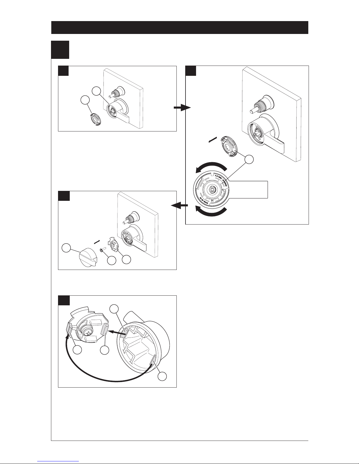
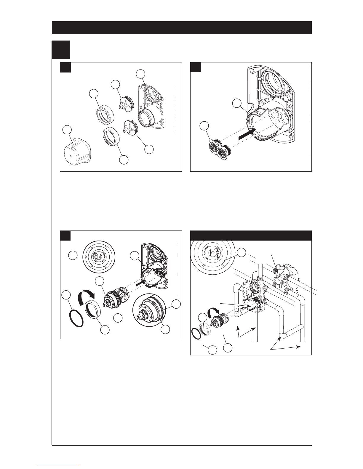
Installation
1
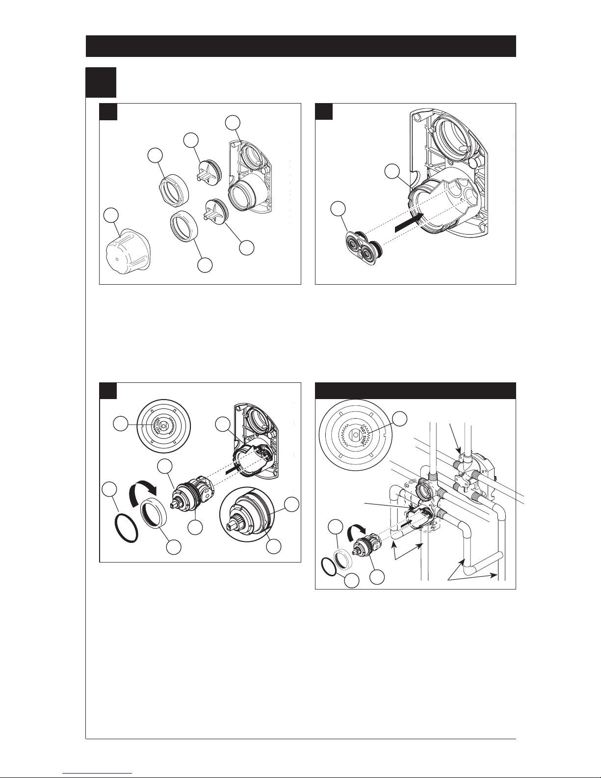
Cartridge Installation
A.
B.
Turn off water supplies. Remove cover (1),
bonnet nuts (2) and test caps (3) from the
rough-in body (4).
Place a bucket or small container over the front
of the valve body and slowly open the water
supplies to ush any debris from the supply
lines before installing the cartridge. Turn the
water supplies back off.
Insert adapter assembly (1) into rough-in
body (2). Make sure the adapter assembly
is correctly positioned and is pressed all
the way down inside rough-in body.
Rotate cartridge (1) so the words “HOT SIDE”
(2) appear on the left. Insert cartridge assembly
into rough-in body. Make sure the key (3) on the
valve cartridge is fully engaged with the slot in
the brass body (4). Insert bonnet nut (5) over
the cartridge and thread onto the body. Hand
tighten securely, slide o-ring (6) over bonnet
and cartridge. A light coating of plumbers
grease applied to o-rings may aid in assembly.
For the exceptions of back to back or reverse
installations (hot on right and cold on left) only:
Rotate valve cartridge (1) so “HOT SIDE” (2)
appears on the right.
Apply silicone lube to the three o-rings shown
above to make the cartridge easier to install and
remove from the rough-in body.
Install the cartridge making sure that the keys
are fully engaged with the slot in the rough-in
body (see step C).
Slide o-ring (3) and bonnet nut (4) over the
cartridge and thread onto the rough-in body.
Hand tighten securely.
3
C.
Back to back Installation
Normal Installation
(changes not required)
Reverse
Installation
Cold
Hot
1
2
3
4
2
3
1
2
1
2
3
4
5
3
4
2
4
3
1
6
Page 4
102018 Rev. A
Installation
2
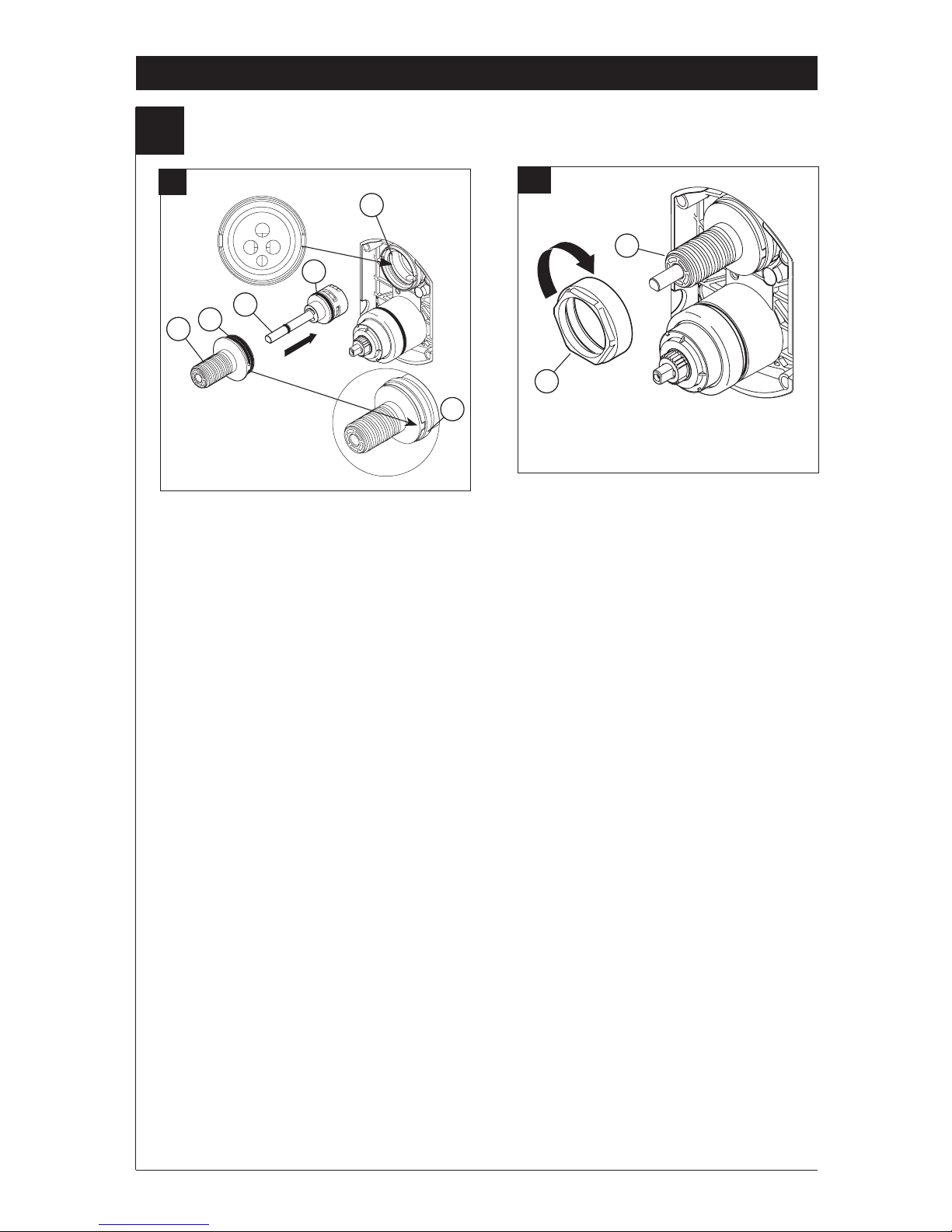
Diverter Cartridge Installation
4
For Bonnet Installation
Slide bonnet nut (1) over diverter sleeve (2)
and thread into rough-in body.
Hand tighten securely.
B.
FOR DIVERTER CARTRIDGE
INSTALLATION:
Apply silicone lube to the o-ring (2) to make
the diverter sleeve (3) easier to install diverter
cartridge. A light coating of plumbers grease
applied to o-rings (4) may aid in assembly.
Install diverter cartridge (1) assuring that the
locating pin on the bottom of the cartridge
aligns with mating hole in rough-in body.
Slide diverter sleeve (3) over cartridge stem
aligning tabs on the diverter sleeve with slots
in rough-in body (5).
A.
3
1
5
2
1
2
5
4
Page 5
102018 Rev. A
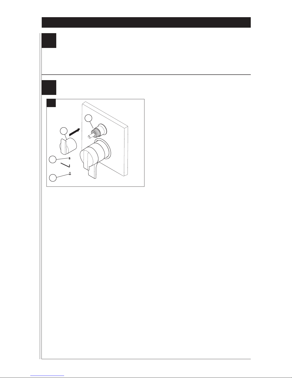
Installation
3
5
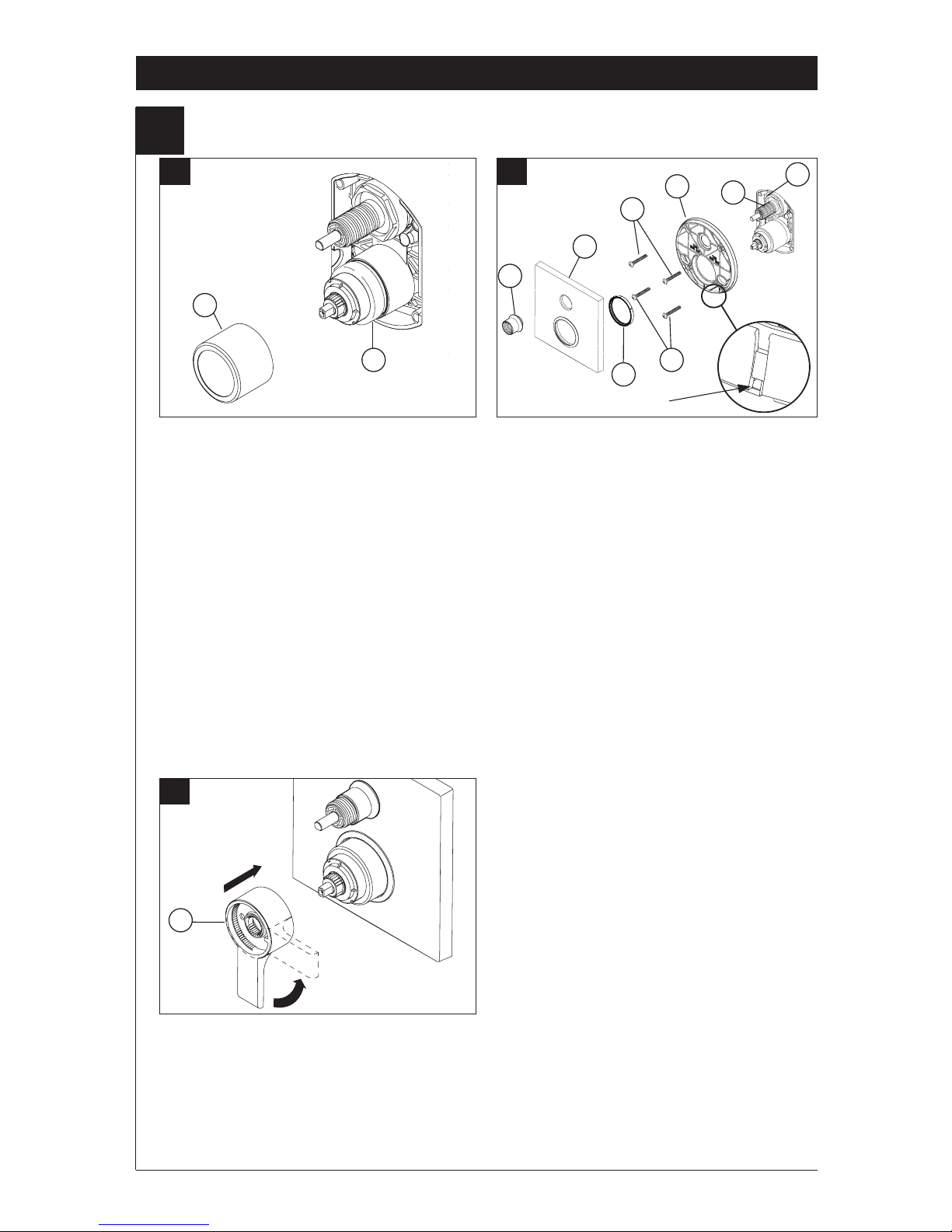
Trim Installation
Trim Sleeve Installation
Slide trim sleeve (1) over the bonnet (2),
cartridge and rough-in body.
Ensure sleeve is properly positioned over the
front of cartridge.
Escutcheon Installation
Note: On models (T27876 & T27976) install
the valve seal (7) onto the back of
escutcheon (4).
For nished wall thickness up to 1 1/8". Secure
the backplate (1) to the rough-in body (2) using 4
screws (3) provided.
Note: Be sure backplate is oriented front side
forward and markings are visible.
Slide escutcheon (4) over diverter cartridge,
thread trim nut (5) onto diverter sleeve (6).
Note: For thick wall installations, order
installation kit RP90543 to support nished
wall thickness up to 2 1/8".
On rough or uneven surfaces it is necessary
to apply caulk around the backplate (1) to
supplement the seal. Do not caulk the drip notch
in the bottom of the backplate (1). Do not caulk
the escutcheon (4).
1
2
A. B.
1
2
5
4
C.
1
Install volume control handle (1) with lever
pointing down, then turn to the on position.
DO NOT SECURE WITH SCREW.
3
3
6
Drip notch
7
Page 6
102018 Rev. A
Installation
4
6
Installation and Adjustment of the Rotational Limit Stop
A.
B.
Place the rotational limit stop (1) in
volume
handle (2) and rotate to the mixed
position (if
required). DO NOT SECURE WITH
SCREW.
Turn on water supplies; let the
water
run until
both hot and cold water is as hot/
cold as
possible. Place thermometer in a plastic tumbler,
and hold the tumbler in the water stream.
Record the temperature reading.
If the water temperature is above 120°F, remove
and rotate the limit stop (1) clockwise one tooth
for every 4°F - 6°F (approximate) change in
temperature. If water temperature is cooler than
desired, rotate the limit stop counterclockwise.
IMPORTANT: The rst position of the Rotational
Limit Stop (the Limiter) is the position that
restricts the rotation of the stem the most and is
at the maximum clockwise setting. According to
industry standards, the maximum allowable
temperature of the water exiting from the valve is
120
o
F. This temperature may vary in your local
area. The Rotational Limit Stop may need to be
readjusted if the inlet water temperature changes.
For instance, during the winter, the cold water
temperature is colder than it is during the summer
which could result in varying outlet temperatures.
Typical temperature for a comfortable bath or
shower is between 90
o
–110o F.
C.
Hotter
Colder
Secure temperature control knob (1) with screw
(2). See next step (D) for securing temperature
control cover (3).
Snap temperature control cover over temperature
control knob by rst aligning smaller tab (1) on
cover with receiving slot (2) on temperature knob.
Swing larger tab (3) to engage with snap feature
(4). Note: If dis-assembly is required, reverse
this motion, disengaging larger tab (3) from snap
feature (4) rst.
1
1
1
2
3
2
D.
4
2
1
3
Page 7
102018 Rev. A
Potential scald or thermal shock injury could result due to cross ow if outlet at the shower is
blocked or restricted (e.g., pause control on showerhead). Be sure to point showerhead away
from you when re-starting ow or install inlet check valves on both supply lines to prevent
possible injury.
7
6
Diverter handle Installation
Diverter Handle Installation
Slide diverter handle (1) onto trim sleeve (2).
Using a allen wrench, insert set screw (3) into
handle (1). Applying pressure, insert set screw
cover (4) until properly seated.
B.
2
1
3
4
Installation
5
Page 8
102018 Rev. A
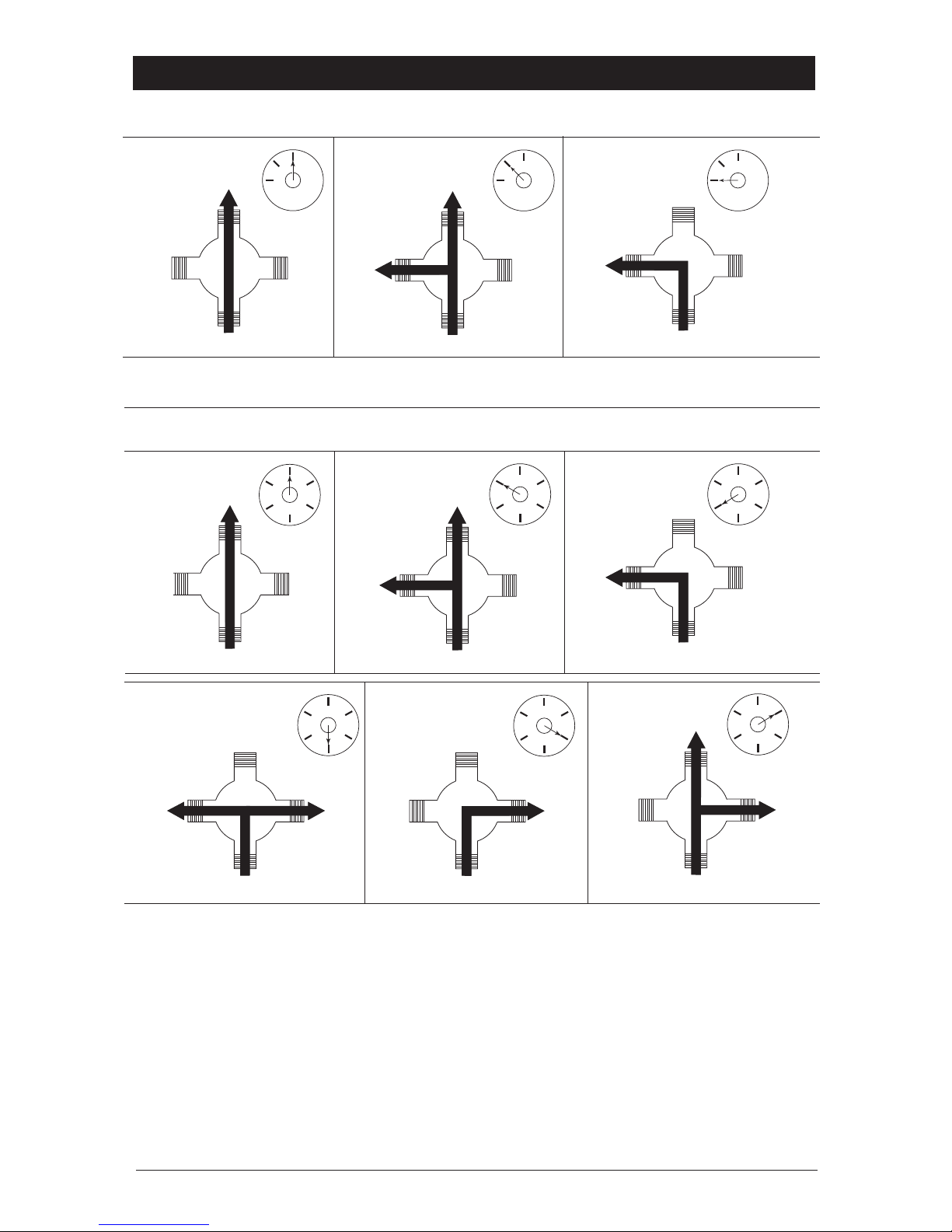
8
Diverter Handle Reference Sheet
2nd Position
2 ª Posición
2e position
3rd Position
3 ª posición
3e position
1st Position
1 ª posición
1ère position
2nd Position
2 ª Posición
2e position
3rd Position
3 ª posición
3e position
Outlet 1
Salida 1
Sortie 1
Outlet 2
Salida 2
Sortie 2
Outlet 3
Salida 3
Sortie 3
In / Entrada / Entrée
4th Position
4 ª posición
4e position
5th Position
5 ª posición
5e position
6th Position
6 ª posición
6e position
Water Flow For 3 Function Diverter / Flujo de agua para Desviadores de 3 posiciones / Écoulement
de l’eau pour les inverseurs à 3 positions
Water Flow For 6 Function Diverter / Flujo de agua para Desviadores de 6 posiciones / Écoulement
de l’eau pour les inverseurs à 6 positions
In / Entrada / Entrée In / Entrada / Entrée
In / Entrada / Entrée
In / Entrada / Entrée
In / Entrada / Entrée
Outlet 1
Salida 1
Sortie 1
Outlet 2
Salida 2
Sortie 2
Outlet 3
Salida 3
Sortie 3
Outlet 1
Salida 1
Sortie 1
Outlet 2
Salida 2
Sortie 2
Outlet 3
Salida 3
Sortie 3
Outlet 1
Salida 1
Sortie 1
Outlet 2
Salida 2
Sortie 2
Outlet 3
Salida 3
Sortie 3
Outlet 1
Salida 1
Sortie 1
Outlet 2
Salida 2
Sortie 2
Outlet 3
Salida 3
Sortie 3
Outlet 1
Salida 1
Sortie 1
Outlet 2
Salida 2
Sortie 2
Outlet 3
Salida 3
Sortie 3
Outlet 1
Salida 1
Sortie 1
Outlet 2
Salida 2
Sortie 2
Outlet 3
Salida 3
Sortie 3
Outlet 1
Salida 1
Sortie 1
Outlet 2
Salida 2
Sortie 2
Outlet 3
Salida 3
Sortie 3
Outlet 1
Salida 1
Sortie 1
Outlet 2
Salida 2
Sortie 2
Outlet 3
Salida 3
Sortie 3
In / Entrada / Entrée
In / Entrada / Entrée
In / Entrada / Entrée
Shared positions do not exist in non-shared cartridges.
Los ajustes o posiciones compartidas no existen en los cartuchos no-compartidos.
Comme leur nom l’indique, les cartouches sans position partagée ne comportent aucune position partagée.
Shared positions do not exist in non-shared cartridges.
Los ajustes o posiciones compartidas no existen en los cartuchos no-compartidos.
Comme leur nom l’indique, les cartouches sans position partagée ne comportent aucune position partagée.
1st Position
1 ª posición
1ère position
Page 9
102018 Rev. A
Clean and Care
Care should be given to the cleaning
of this product. Although its nish is
extremely durable, it can be damaged by
harsh abrasives or polish. To clean, simply
wipe gently with a damp cloth and blot dry
with a soft towel.
Maintenance
Faucet leaks from showerhead:
SHUT OFF WATER SUPPLIES.
Replace valve cartridge
RP46463 or RP32104
See Helpful Hints 1, 2, 3 & 4.
Helpful Hints:
1. Before removing valve cartridge assembly for any
maintenance, be sure to note the position of the
rotational limit stop on the cap. The valve cartridge
assembly must always be put back in the same
position. BE SAFE! After you have nished the
installation, turn on valve to make sure COLD
WATER FLOWS FIRST.
2. To remove valve cartridge from body, shut off
water supplies and remove handle and bonnet nut.
Do not pry the valve cartridge out of the body with
a screwdriver. Place handle on stem and rotate
counterclockwise approximately 1/4 turn after the
stop has been contacted. Lift valve cartridge out
of body.
Remove seats and springs and replace.
Place the largest diameter of the spring into the
seat pocket rst and then press the tapered end
of the seal over the spring. Reassemble valve
cartridge and replace in body following instructions
given in 1 above.
3. If the water in your area has lime, rust, sand
or other contaminants in it, your pressure
balance valve will require periodic inspection.
The frequency of the inspection will depend
on the amount of contaminants in the water. To
inspect valve cartridge remove it and follow the
steps in note 1 above. Turn the valve to the full
mix position and shake the cartridge vigorously.
If there is a rattling sound, the unit is functional
and can be reinstalled following instructions given
in note 1 above. If there is no rattle, replace the
housing assembly with the proper RP.
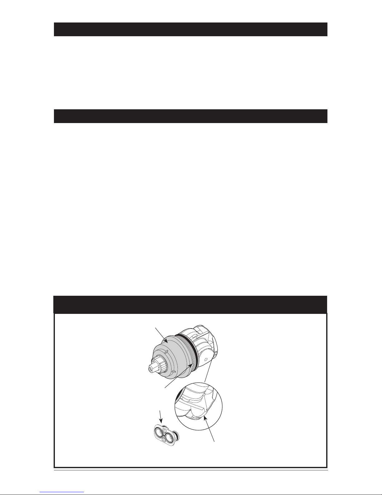
Cartridge Summary Reference Sheet
Order RP46463 to
Replace Cartridge.
Grey Upper Cap
V Notch
Adapter
Shorter Tab
T27
9
Page 10

102018 Rev. A
Page 11

Instrucciones para la
instalación del Accesorio de la
VálvulMultiChoice® con desviador
Manual para propietarios
Escriba el número del modelo aquí.
Puede necesitar
ESTA VALVULA cumple o excede las siguientes
normas: ASME A112.18.1 / CSA B125.1 y ASSE 1016
(Tipo -P- o -T-).
ADVERTENCIA: Este sistema/dispositivo debe
congurarse por el instalador para asegurar una
temperatura máximo segura. Cualquier cambio en el ajuste
puede aumentar la temperatura de salida por encima del
límite considerado seguro y puede dar lugar a quemaduras
por agua caliente.
AVISO PARA EL INSTALADOR: ¡ATENCIÓN! -Como
el instalador de esta válvula, es su responsabilidad
de INSTALAR y AJUSTAR correctamente esta válvula
según las instrucciones proporcionadas. Esta válvula
no se ajusta automáticamente a los cambios de
temperatura de entrada, por lo tanto, alguien debe
hacer los ajustes necesarios al Tope del Límite
Rotacional en el momento de la instalación y ajustes
adicionales pueden ser necesarios debido a cambios
estacionales de la temperatura del agua. USTED
DEBE informar al propietario/usuario de este requisito
siguiendo las instrucciones. Si usted o el dueño/
consumidor no está seguro de como hacer estos ajustes,
por favor consulte la página 6 y si aún tiene duda,
llámenos al 1-800-345-DELTA.
Después de la instalación y el ajuste, debe colocar su
nombre, nombre de la empresa y la fecha en que ajustó la
perilla de control de la temperatura a la etiqueta de
precaución proporcionada y aplique o pegue la etiqueta en
la parte trasera de la puerta del armario más cercano y la
etiqueta de advertencia al calentador de agua.
Deje esta hoja de instrucciones para referencia del
propietario /usuario.
ADVERTENCIA: Esta válvula termostática de baño está
diseñada para minimizar los efectos de los cambios
de temperatura del agua de salida debido a cambios
de presión y temperatura, causados habitualmente
por los lavaplatos, las lavadoras, los inodoros y otros
aparatos similares. Puede no ofrecer protección contra
las quemaduras por agua caliente cuando hay un fallo
de otros dispositivos para el control de temperatura
en otras partes del sistema de plomería, si el Tope del
Límite Rotacional no está congurado correctamente
o si se cambia la temperatura del agua caliente
después de realizar los ajustes o si el agua admisión
cambia debido a los cambios estacionales.
ADVERTENCIA: No instale un dispositivo de cierre en
cualquiera de las tuberías de salida de agua de esta
válvula. Cuando este tipo de dispositivo cierra el ujo
del agua, pueda aminorar el propósito de la válvula
para balancear las presiones del agua caliente y fría.
Rev. A03/15/2018 1
Tabla de contenido:
Garantía ............................................................................... Página 2
Instrucciones de instalación ................................................ Páginas 3 - 7
Limpieza y cuidado .............................................................. Página 9
Mantenimiento ...................................................................... Página 9
Hoja de referencia para el Cartucho .................................... Página 9
Piezas de repuesto para la serie Classic ............................. Página 10-16
Para obtener piezas de repuesto adicionales, visite www.deltafaucet.com
T27859, T27867, T27876,
T27897, T27899, T27959,
T27967, T27976, T27997 &
T27999 Series
102018
Page 12

102018 Rev. A
2
Piezas y Acabado
Todas las piezas (menos las piezas electrónicas y las pilas) y acabados de esta llave de agua - grifo Delta® están garantizados al consumidor comprador original, de estar libres de defectos en materiales y mano de obra durante el tiempo que el comprador original sea dueño de la casa en la cual
la llave de agua fue instalada por primera vez o, para los usuarios comerciales, por cinco (5) años desde la fecha de compra.
Piezas electrónicas y las baterías/pilas (si aplicable)
Las piezas electrónicas (excepto las baterías), sea el caso, de este grifo Delta® están garantizadas al consumidor comprador original, de estar libres
de defectos en materiales y mano de obra durante 5 años desde la fecha de compra o, para los usuarios comerciales, durante un año desde la fecha
de compra. La garantía no cubre las baterías.
Delta Faucet Company reparará o reemplazará, SIN COSTO ALGUNO, durante el período de garantía aplicable, cualquier pieza o acabado que
presente defectos en materiales y/o mano de obra bajo instalación, uso y servicio normal. Si la reparación o sustitución no es práctica, Delta Faucet
Company podrá optar reintegrarle el precio de la compra a cambio de la devolución del producto. Estos son sus únicos recursos.
Delta Faucet Company recomienda que use un plomero profesional para todas las instalaciones y reparación. También recomienda que utilice sólo
piezas de repuesto Delta®.
Delta Faucet Company no será responsable de cualquier daño a la llave de agua/grifo resultante del uso indebido, abuso, negligencia o uso inapropiado o instalación realizada de forma incorrecta, mantenimiento o reparación, incluyendo el no seguir las instrucciones de cuidado y limpieza
aplicables.
Las piezas de repuesto se pueden obtener llamando al número que figura más abajo o escribiendo a:
En los Estados Unidos y Mexico: En Canadá:
Delta Faucet Company Masco Canada Limited, Plumbing Group
Product Service Technical Service Centre
55 E. 111th Street 350 South Edgeware Road
Indianapolis, IN 46280 St. Thomas, Ontario, Canada N5P 4L1
1-877-345-DELTA (3358) 1-877-345-DELTA (3358)
customerservice@deltafaucet.com customerservice@mascocanada.com
La prueba de compra (recibo original de venta) del comprador original debe ponerse a la disposición de Delta Faucet Company para todos los reclamos de garantía a menos que el comprador haya registrado el producto con Delta Faucet Company. Esta garantía se aplica solamente a las llaves de
agua/grifos Delta® fabricadas después de 1 de enero de 1995 e instalados en los Estados Unidos de América, Canadá y México.
DELTA FAUCET COMPANY NO SERÁ RESPONSABLE POR DAÑOS ESPECIALES, INCIDENTALES O CONSECUENTES (INCLUYENDO
CARGOS DE LABOR) YA SEAN RESULTANTES DEL INCUMPLIMIENTO DE CUALQUIER GARANTÍA EXPRESA O IMPLÍCITA DE LA LLAVE DE
AGUA/GRIFO. Algunos estados/provincias no permiten la exclusión o limitación de daños especiales, incidentales o consecuentes, por lo que estas
limitaciones y exclusiones pueden no aplicarle en su caso.
Esta garantía le otorga derechos legales especiales, y usted también puede tener otros derechos que varían de estado/provincia a estado/provincia.
Esta es la garantía exclusiva por escrito de Delta Faucet Company’s, y la garantía no es transferible.
Si usted tiene alguna pregunta o inquietud acerca de nuestra garantía, por favor vea nuestra sección de Preguntas Frecuentes sobre la garantía www.deltafaucet.com, email us at customerservice@deltafaucet.com.
Garantía limitada de por vida de la llave de agua y acabado
© 2017 Masco Corporación of Indiana
Page 13
102018 Rev. A
Instalación
1
Instalación del cartucho
A.
B.
Cierre los suministros de agua. Quite la tapa (1),
tuercas tapas (2) y las tapas de prueba (3) del cuerpo
de la tubería preliminar detrás de la pared (4).
Coloque una cubeta o recipiente pequeño sobre el
frente del cuerpo de la válvula y abra lentamente los
suministros de agua para eliminar cualquier residuo de
las líneas de suministro antes de instalar el cartucho.
Cierre otra vez el agua de suministro.
Introduzca el ensamble del adaptador (1) en
el cuerpo de la tubería preliminar interna (2).
Asegúrese de que el ensamble del adaptador está
colocado correctamente y está presionado hasta el
fondo dentro del cuerpo preliminar.
Gire el cartucho de la válvula (1) de forma que las
palabras "HOT SIDE" estén en el lado izquierdo.
Inserte el cartucho en el cuerpo de la tubería
preliminar. Asegúrese de que el dentado en el
cuerpo está totalmente encajado en la muesca en
el cuerpo de bronce (4). Introduzca la tuerca tapa
(5) en el cartucho y enrosque en el cuerpo. Apriete
bien, a mano y deslice la junta tórica (6) en el
casquete y el cartucho.
La aplicación de una ligera capa de grasa de
plomeros en las juntas tóricas puede facilitar el
montaje.
Solo para las excepciones de dorso con dorso o
instalaciones inversas (caliente en la derecha y fría
en la izquierda): Gire el cartucho de la válvula (1) de
forma que "HOT SIDE" aparece en la derecha.
Aplique lubricante de silicona en las tres juntas
tóricas mostradas arriba para facilitar la instalación
del cartucho y quitar del cuerpo de la tubería
preliminar.
Instale el cartucho asegurándose de que los
dentados están totalmente encajados en la ranura en
el cuerpo de la tubería preliminar (véase el paso C).
Deslice la junta tórica (3) y la tuerca tapa (4) sobre
el cartucho y enrosque en el cuerpo de la tubería
preliminar. Apriete con la mano de forma segura.
3
C.
Instalación de dorso con dorso.
Instalación normal
(no se requieren cambios)
Reverse
Installation
Cold
Hot
1
2
3
4
2
3
1
2
1
2
3
4
5
3
4
2
4
3
1
6
Page 14

102018 Rev. A
Instalación
2
Instalación del cartucho de desvío
4
Para la instalación del casquete
Deslice la tuerca tapa (1) sobre el casquillo
desviador (2) y enrosque en el cuerpo de la
tubería preliminar.
Apriete a mano de forma segura.
B.
PARA LA INSTALACIÓN DEL CARTUCHO DE
DESVÍO:
Aplique lubricante de silicona a la junta tórica (2)
para facilitar la instalación del cartucho desviador
con el casquillo desviador (3). La aplicación
de una ligera capa de grasa de plomeros a las
juntas tóricas (4) puede facilitar el montaje.
Gire el cartucho desviador (1) asegurando que el
pasador de posicionamiento que está en la parte
inferior del cartucho se alinee con el agujero
correspondiente en el cuerpo de la tubería
preliminar.
Deslice el casquillo desviador (3) sobre la espiga
del cartucho alineando las lengüetas en el
casquillo desviador con ranuras en el cuerpo de
la tubería preliminar (5).
A.
3
1
5
2
1
2
5
4
Page 15

102018 Rev. A
Instalación
3
5
Instalación del accesorio
Instalación del casquillo del accesorio
Deslice el casquillo del accesorio (1) sobre el
casquete (2), el cartucho y el cuerpo de la tubería
preliminar.
Asegúrese que el casquillo está correctamente
colocado sobre el frente del cartucho.
Instalación del chapetón
Nota: En los modelos (T24876 y T24976) instale
el sello de la válvula (7) en la parte posterior del
chapetón (4).
Para paredes acabadas de un grosor hasta 1 1/8".
Fije la placa posterior (1) al cuerpo de la unidad de
las tuberías preliminares (2) usando los 4 tornillos
(3) proporcionados.
Nota: asegúrese que la placa trasera está
colocada con el frente hacia adelante y con las
marcas visibles.
Deslice el chapetón o chapa de cubierta (4) sobre
el cartucho desviador, enrosque la tuerca del
accesorio (5) proporcionada en el casquillo del
desviador.
Nota: para instalaciones en paredes gruesas,
ordene el juego de piezas RP90543 para
sostener la pared acabada hasta de 2 1/8" de
grosor.
En supercies rugosas o desiguales, es necesario
aplicar masilla alrededor de la placa posterior
(1) para complementar el sello. No calafatee el
chapetón (4).
1
2
A. B.
1
2
5
4
C.
1
Instale la manija para el control de; volumen
(1) con la palanca hacia abajo, luego gire a la
posición abierta. NO FIJE CON EL TORNILLO.
3
3
Muesca de goteo
7
6
Page 16

102018 Rev. A
Instalación
4
6
Instalación y ajuste del tope del límite rotacional
B.
Coloque la perilla para el control de temperatura (1)
en la palanca de volumen y gire a la posición mixta
(si es necesario). NO FIJE CON EL TORNILLO.
Abra los suministros de agua; deje que el agua
uya hasta que esté lo más caliente/fría posible.
Coloque un termómetro en un vaso plástico, y
sostenga el vaso bajo el chorro de agua. Registre
la lectura de la temperatura.
Si la temperatura del agua está por encima de
120° F, retire y gire el tope (1) un diente hacia la
derecha por cada 4° F - 6° F (aproximadamente)
cambio en la temperatura. Si la temperatura del
agua es más fría que lo deseada, gire el tope
hacia la izquierda.
IMPORTANTE: La primera posición del Tope del
Límite Rotacional (el limitador) es la posición que
más restringe la rotación e la espiga y está en
el ajuste máximo hacia la derecha. De acuerdo
con los estándares de la industria, la temperatura
máxima permisible del agua que sale de la
válvula es 120° F. Esta temperatura puede variar
en su área local.
El Tope del Límite Rotacional puede requerir
reajuste si cambia la temperatura del agua
de entrada. Por ejemplo, durante el invierno,
la temperatura del agua fría es más fría de lo
que es durante el verano que podría resultar
en una variación de temperaturas de salida. La
temperatura típica para un baño o una ducha
confortable es entre 90o-110o F.
Hotter
Colder
Fije la perilla para el control de la temperatura (1)
con el tornillo (2). Para jar la tapa del control de
temperatura (3), vea el próximo paso (D).
1
A.
1
1
2
3
C.
Coloque a presión la tapa del control de temperatura sobre
el pomo del control de temperatura alineando primero la
lengüeta más pequeña (1) con la muesca para encajar
en la cubierta (2) ubicada en el pomo de temperatura.
Gire la lengúeta más grande (3) para que encaje con el
mecanismo de presión (4). Nota: Si requiere desarmar,
repita estos pasos en reverso, desencajando primero la
lengúeta más grande (3) del mecanismo de presión (4).
D.
4
2
1
3
Page 17

102018 Rev. A
Existe la posibilidad de lesión por escaldadura o de choque térmico resultante de un ujo cruzado
en el caso que la salida de la regadera/ducha está bloqueada o restringida (por ejemplo, pause el
control de la cabeza de la regadera/ducha). Asegúrese de apuntar la regadera/ducha alejado de
usted cuando vuelva a iniciar el ujo o instale las válvulas de retención de la entrada en ambas
líneas de suministro para evitar posibles lesiones.
7
Instalación del desviador de la manija
Instalación del desviador de la manija
Inserte la manija del desviador (1) sobre el
casquillo del accesorio (2). Usando una llave allen,
inserte el tornillo de jación/ajuste (3) en la manija
(1). Aplicando presión, inserte la tapa del tornillo
de ajuste (4) hasta que esté bien asentada.
6
B.
2
1
3
4
Installation
5
Page 18

102018 Rev. A
8
Hoja de referencia para la manija desviadora
2nd Position
2 ª Posición
2e position
3rd Position
3 ª posición
3e position
1st Position
1 ª posición
1ère position
2nd Position
2 ª Posición
2e position
3rd Position
3 ª posición
3e position
Outlet 1
Salida 1
Sortie 1
Outlet 2
Salida 2
Sortie 2
Outlet 3
Salida 3
Sortie 3
In / Entrada / Entrée
4th Position
4 ª posición
4e position
5th Position
5 ª posición
5e position
6th Position
6 ª posición
6e position
Water Flow For 3 Function Diverter / Flujo de agua para Desviadores de 3 posiciones / Écoulement
de l’eau pour les inverseurs à 3 positions
Water Flow For 6 Function Diverter / Flujo de agua para Desviadores de 6 posiciones / Écoulement
de l’eau pour les inverseurs à 6 positions
In / Entrada / Entrée In / Entrada / Entrée
In / Entrada / Entrée
In / Entrada / Entrée
In / Entrada / Entrée
Outlet 1
Salida 1
Sortie 1
Outlet 2
Salida 2
Sortie 2
Outlet 3
Salida 3
Sortie 3
Outlet 1
Salida 1
Sortie 1
Outlet 2
Salida 2
Sortie 2
Outlet 3
Salida 3
Sortie 3
Outlet 1
Salida 1
Sortie 1
Outlet 2
Salida 2
Sortie 2
Outlet 3
Salida 3
Sortie 3
Outlet 1
Salida 1
Sortie 1
Outlet 2
Salida 2
Sortie 2
Outlet 3
Salida 3
Sortie 3
Outlet 1
Salida 1
Sortie 1
Outlet 2
Salida 2
Sortie 2
Outlet 3
Salida 3
Sortie 3
Outlet 1
Salida 1
Sortie 1
Outlet 2
Salida 2
Sortie 2
Outlet 3
Salida 3
Sortie 3
Outlet 1
Salida 1
Sortie 1
Outlet 2
Salida 2
Sortie 2
Outlet 3
Salida 3
Sortie 3
Outlet 1
Salida 1
Sortie 1
Outlet 2
Salida 2
Sortie 2
Outlet 3
Salida 3
Sortie 3
In / Entrada / Entrée
In / Entrada / Entrée
In / Entrada / Entrée
Shared positions do not exist in non-shared cartridges.
Los ajustes o posiciones compartidas no existen en los cartuchos no-compartidos.
Comme leur nom l’indique, les cartouches sans position partagée ne comportent aucune position partagée.
Shared positions do not exist in non-shared cartridges.
Los ajustes o posiciones compartidas no existen en los cartuchos no-compartidos.
Comme leur nom l’indique, les cartouches sans position partagée ne comportent aucune position partagée.
1st Position
1 ª posición
1ère position
Page 19

102018 Rev. A
Limpieza y Cuidado
Se debe tener cuidado con la limpieza de este producto.
Aunque su acabado es extremadamente resistente, puede
ser dañado por abrasivos o pulimentos ásperos. Para
limpiar, simplemente frote con un paño húmedo y seque con
una toalla suave.
Mantenimiento
Si hay ltración de agua desde la llave de agua/grifo de
la regadera:
CIERRE LOS SUMINISTROS DE AGUA. Reemplace la
válvula de cartucho o RP46463 RP32104
Vea Consejos útiles 1, 2, 3 y 4
Sugerencias útiles:
1. Antes de retirar el ensamble del cartucho de la válvula
para cualquier tarea de mantenimiento, asegúrese de anotar
la posición del tope de rotación en la tapa. El ensamble del
cartucho de la válvula siempre debe ser puesto de nuevo
en la misma posición. ¡CUIDESE! Después de que haya
terminado la instalación, abra la válvula para asegurarse de
que el agua FLUYE FRÍA PRIMERO.
2. Para extraer el cartucho de la válvula del cuerpo, cierre
el suministro de agua y retire la manija y la tuerca tapa. No
se debe quitar el cartucho de la válvula del cuerpo con un
destornillador. Coloque la manija en la espiga y gire hacia
la izquierda aproximadamente 1/4 de vuelta después que el
tope tenga contacto. Levante el cartucho de la válvula del
cuerpo.
Retire los asientos y resortes y reemplácelos.
Primero, coloque el diámetro mayor del resorte en el
bolsillo del asiento y luego presione el extremo cónico de
la junta sobre el resorte. Vuelva a ensamblar el cartucho
de la válvula y colóquelo de nuevo en el cuerpo, siguiendo
las instrucciones dadas en el punto 1.
3. Si el agua en su área contiene cal, óxido, arena u
otros contaminantes, su válvula de equilibrio de presión
requerirá una inspección periódica.
La frecuencia de la inspección dependerá de la cantidad
de contaminantes en el agua. Para inspeccionar el
cartucho de la válvula y quitarla y siga los pasos indicados
en la nota 1 anterior. Gire la válvula a la posición de
mezcla completa y agite el cartucho con fuerza.
Si hay un sonido de traqueteo, la unidad es funcional y se
puede volver a instalar siguiendo las instrucciones dadas
en la nota 1 anterior. Si no hay traqueteo, reemplace
el conjunto de la cubierta con la pieza de repuesto/RP
adecuada.
Hoja de resumen de referencia para el cartucho
Ordene RP46463 para
Reemplazar cartucho.
Tapa superior Gris
Muesca V
Adaptador
Lengüeta más corta
T27
9
Page 20

102018 Rev. A
Page 21

Instructions d'installation
Soupape MultiChoice® avec
inverseur
Manuel d'utilisation
Inscrivez le numéro du modèle acheté
ici.
Ce dont vous pouvez avoir besoin
CETTE SOUPAPE RESPECTE OU SURPASSE LES
NORMES SUIVANTES : ASME A112.18.1/ CSA B125.1 et
ASSE 1016 (Type -P- ou -T-).
ATTENTION: Ce système ou cet appareil doit être réglé
par l’installateur pour que sa température maximale soit
sans danger. Tout changement du réglage peut entraîner
une hausse de température au delà de la limite considérée
sécuritaire et occasionner l’ébouillantage.
AVIS À L'INSTALLATEUR: ATTENTION! - En qualité
d’installateur de cette soupape, vous avez la
responsabilité de L’INSTALLER et de la RÉGLER
correctement selon les instructions fournies. Cette
soupape ne s’adapte pas automatiquement aux
uctuations de la température de l’eau d’alimentation.
Par conséquent, il faut régler la butée de température
maximale au moment de l’installation et il peut être
nécessaire de faire de nouveaux réglages par la
suite en raison des fluctuations saisonnières de
la température de l’eau. VOUS DEVEZ informer le
propriétaire ou l’utilisateur de cette exigence. En cas de
doute quant à la marche à suivre pour faire ces réglages,
veuillez consulter la page 6. Si vous avez encore des
doutes, veuillez appeler au 1-800-345-DELTA.
Après avoir terminé l’installation et le réglage, vous devez
inscrire, sur l’étiquette de mise en garde fournie, votre nom,
le nom de votre entreprise et la date à laquelle vous avez
réglé la butée de température maximale, puis xer l’étiquette
à l’endos de la porte de la coiffeuse. Vous devez également
xer l’étiquette d’avertissement au chauffe-eau.
Veuillez laisser ce feuillet d’instructions au propriétaire
ou à l’utilisateur pour qu’il puisse le consulter au
besoin.
MISE EN GARDE – Ce robinet thermostatique à
équilibrage de pression pour baignoire est conçu
pour limiter les effets des uctuations de température
de l’eau causées par les variations de la pression
d’alimentation attribuables au fonctionnement d’un
lave-vaisselle, d’une machine à laver, d’un cabinet
d’aisances ou d’un autre appareil qui consomme
de l’eau. Il peut ne pas protéger l’utilisateur contre
l’échaudage en cas de défectuosité d’un autre
dispositif de régulation de la température, de réglage
erroné de la butée de température maximale, de
modication de la température de l’eau chaude après
le réglage de la butée de température maximale ou
de uctuation saisonnière de la température de l’eau
d’alimentation.
MISE EN GARDE – N’installez pas de dispositif d’arrêt
sur une sortie quelconque de cette soupape. En
interrompant l’écoulement de l’eau, ce dispositif peut
empêcher la soupape d’équilibrer les pressions d’eau
chaude et d’eau froide.
Rev. A03/15/2018 1
Table des matières:
Garanties ................................................................................... Page 2
Instructions d'installation ........................................................... Pages 3 - 7
Nettoyage et entretien ............................................................... Page 9
Maintenance .............................................................................. Page 9
Fiche de référence sommaire de la cartouche .......................... Page 9
Pièces de rechange de la série Classic .................................... Page 10-16
Pour obtenir de l’information sur d’autres pièces de rechange, visitez : www.deltafaucet.com
T27859, T27867, T27876,
T27897, T27899, T27959,
T27967, T27976, T27997 &
T27999 Series
102018
Page 22

102018 Rev. A
2
Pièces et finis
Toutes les pièces et tous les finis de ce robinet Delta® sont protégés contre les défectuosités du matériau et les vices de fabrication par une garantie
qui est consentie au premier acheteur et qui demeure valide tant que celui-ci demeure propriétaire de la maison dans laquelle l’accessoire a été
installé. Dans le cas d’une utilisation commerciale, la garantie est de 5 ans à compter de la date d’achat.
Composants électroniques et piles (le cas échéant)
Si ce robinet Delta® comporte des composants électroniques, ces composants (à l’exception des piles) sont protégés contre les défectuosités du
matériau et les vices de fabrication par une garantie consentie au premier acheteur qui est d’une durée de 5 ans à compter de la date d’achat. Dans
le cas d’une utilisation commerciale, la garantie est d’un an à compter de la date d’achat. Aucune garantie ne couvre les piles.
Pendant la période de garantie applicable, Delta Faucet Company réparera ou remplacera GRATUITEMENT toute pièce qui présentera une défectuosité de matériau et/ou un vice de fabrication pour autant que le produit ait été installé, utilisé et entretenu normalement. S’il est impossible de réparer
ou de remplacer le produit, Delta Faucet Company pourra rembourser le prix d’achat en échange du produit retourné. Il s’agit de vos seuls recours.
Delta Faucet Company recommande de confier l’installation et la réparation à un plombier professionnel. Nous vous recommandons également d’utiliser uniquement des pièces de rechange d’origine Delta®.
Delta Faucet Company se dégage de toute responsabilité à l’égard de toute détérioration du produit résultant d’une usure raisonnable et des dommages causés par un mauvais usage, un usage abusif, la négligence ou l’utilisation d’une méthode d’installation, de maintenance ou de réparation
incorrecte ou inadéquate, y compris les dommages résultant du non-respect des instructions de nettoyage et d’entretien applicables.
Vous pouvez obtenir des pièces de rechange en appelant au numéro de téléphone ci-dessous ou en écrivant à:
Aux États-Unis et au Mexique: Au Canada:
Delta Faucet Company Masco Canada Limited, Groupe plomberie
Product Service Centre de services techniques
55 E. 111th Street 350 South Edgeware Road
Indianapolis, IN 46280 St. Thomas, Ontario, Canada N5P 4L1
1-877-345-DELTA (3358) 1-877-345-DELTA (3358)
customerservice@deltafaucet.com customerservice@mascocanada.com
La preuve d’achat (reçu original) du premier acheteur doit être présentée à Delta Faucet Company pour toutes les demandes en vertu de la garantie,
sauf si le produit a été enregistré auprès de Delta Faucet Company. La présente garantie s’applique uniquement aux accessoires Delta® installés aux
États-Unis d’Amérique, au Canada et au Mexique.
DELTA FAUCET COMPANY SE DÉGAGE DE TOUTE RESPONSABILITÉ À L’ÉGARD DES DOMMAGES PARTICULIERS, CONSÉCUTIFS ET
INDIRECTS (Y COMPRIS LES FRAIS DE MAIN-D’ŒUVRE ) QUI DÉCOULENT D’UNE RUPTURE D’UNE GARANTIE IMPLICITE OU EXPLICITE
DU ROBINET. Dans les États ou les provinces où il est interdit d’exclure ou de limiter les dommages particuliers, consécutifs ou indirects, les exclusions ou les limites susmentionnées ne s’appliquent pas. La présente garantie vous procure des droits particuliers reconnus par la loi. Vous pouvez
avoir d’autres droits qui varient selon l’État ou la province.
La présente garantie écrite est la seule garantie offerte par Delta Faucet Company et elle n’est pas transférable.
Si vous avez des questions ou des préoccupations en ce qui concerne notre garantie, veuillez consulter la page Warranty FAQs à www.deltafaucet.com, nous
faire parvenir un courriel à customerservice@deltafaucet.com ou nous appeler au numéro applicable.
Garantie à vie sur le robinet et garantie limitée sur le ni
© 2017 Division de Masco Indiana
Page 23

102018 Rev. A
Installation
1
Installation de la cartouche
A.
B.
Fermez les robinets d’alimentation. Retirez
le capuchon (1), les écrous-chapeaux (2) et les
capuchons d'essai (3) du corps de robinetterie brute (4).
Placez un seau ou un petit contenant sur l’avant du
corps de soupape et ouvrez lentement les robinets
d’arrêt pour évacuer les corps étrangers de la
tuyauterie avant d’installer la cartouche. Fermez de
nouveau les robinets d’arrêt.
Introduisez l’adaptateur (1) dans le corps de
robinetterie brute (2). Assurez-vous que l'adaptateur
est positionné correctement et bien calé dans le
corps de robinet brut.
Tournez la cartouche (1) de sorte que la mention «
HOT SIDE » (2) se trouve du côté gauche. Introduisez
la cartouche dans le corps de robinetterie brute.
Assurez-vous que l’ergot (3) sur la cartouche est
parfaitement engagé dans la rainure du corps en
laiton (4). Insérez l'écrou-chapeau (5) sur la cartouche
et vissez-le sur le corps. Serrez-le à la main
solidement, glissez le joint torique (6) sur l'écrou-
chapeau et la cartouche. Vous pouvez enduire les
joints toriques d’un peu de graisse de plomberie pour
faciliter l’assemblage.
Dans le cas d’une installation dos à dos ou inversée
(eau chaude à droite et eau froide à gauche)
seulement : tournez la cartouche (1) de sorte que la
mention « HOT SIDE » se trouve du côté droit.
Ajoutez du lubriant à base de silicone aux trois joints
toriques montrés ci-dessus pour faciliter la pose de
la cartouche dans le corps de robinetterie brute et sa
dépose.
Installez la cartouche en prenant soin d’introduire
les ergots entièrement dans les rainures du corps de
robinetterie brute (reportez-vous à l’étape C).
Glissez le joint torique (3) et l'écrou-chapeau (4) sur
la cartouche et vissez-le sur le corps de robinet brut.
Serrez-le à la main solidement.
3
C.
Installation dos à dos
Installation normale
(aucun changement requis)
Installation
inversée
Froid
Chaud
1
2
3
4
2
3
1
2
1
2
3
4
5
3
4
2
4
3
1
6
Page 24

102018 Rev. A
Installation
2
Installation de la cartouche de l’inverseur
4
Installation du chapeau
Glissez l'écrou-chapeau (1) sur le manchon
de l'inverseur (2) et vissez-le sur le corps de
robinetterie brute.
Serrez-le à la main solidement.
B.
INSTALLATION DE LA CARTOUCHE DE
L'INVERSEUR
Ajoutez du lubriant à base de silicone au joint
torique (2) pour faciliter la pose du manchon de
l'inverseur (3) et la cartouche de l’inverseur. Vous
pouvez enduire les joints toriques (4) d’un peu de
graisse de plomberie pour faciliter l’assemblage.
Installez la cartouche d'inverseur (1) en prenant
soin de faire correspondre l'ergot de détrompage au
bas de la cartouche avec le trou dans le corps de
robinet brut.
Glissez le manchon de l'inverseur (3) sur la tige de
la cartouche en faisant correspondre les pattes du
manchon de l'inverseur avec les rainures dans le
corps de robinetterie brute (5).
A.
3
1
5
2
1
2
5
4
Page 25

102018 Rev. A
Installation
3
5
Installation de la pièce de nition
Installation du manchon de nition
Glissez le manchon de nition (1) sur le chapeau (2),
la cartouche et le corps de robinetterie brute.
Assurez-vous que le manchon est bien positionné
sur l'avant de la cartouche.
Installation de la plaque de nition
Note:
Note: Sur les modèles (T24876 et T24976),
installez le joint de soupape (7) à l'arrière de l'écusson
(4).
Installation dans un mur ni d’une épaisseur maximale
de 1 1/8 po. Fixez la plaque arrière (1) au corps de
robinetterie brute (2) au moyen des quatre vis (3)
fournies.
Note : Assurez-vous que la face avant de la plaque
arrière est orientée vers l’avant et que les repères
sont visibles.
Glissez la plaque de nition (4) sur la cartouche de
l'inverseur, puis vissez l'écrou de nition (5) fourni sur
le manchon de l'inverseur.
Note : Si vous faites l'installation dans un mur
épais, commandez la trousse d'installation
RP90543 pour un mur ni d'une épaisseur
maximale de 2 1/8 po.
Sur les surfaces raboteuses ou inégales, vous devez
appliquer du composé d'étanchéité autour de la
plaque arrière (1) pour épaissir le joint. N'appliquez
pas de de composé d'étanchéité dans l’encoche
d’égouttement au bas de la plaque arrière (1) ni autour
de la plaque de nition (4).
1
2
A.
C.
1
Installez la manette de réglage de débit (1) de
manière qu’elle pointe vers le bas, puis placez-la
en position d’ouverture. NE LA FIXEZ PAS AVEC
UNE VIS.
B.
1
2
5
4
3
3
6
Goutte à goutte
7
Page 26

102018 Rev. A
Installation
4
6
Installation et réglage de la butée de température maximale
Placez le bouton de réglage de température (1) sur la
manette de réglage de débit et tournez-le jusqu’à la
position de mélange (au besoin). NE LE FIXEZ PAS
AVEC LA VIS. Rétablissez l’alimentation en eau. Laissez
couler l’eau jusqu’à ce que l’eau froide soit aussi froide
que possible et que l’eau chaude soit aussi chaude
que possible. Mettez un thermomètre dans un gobelet
en plastique, puis placez le gobelet sous le jet d’eau et
attendez un peu. Notez la température de l’eau.
Si la température de l'eau est supérieure à 120
°F, retirez et tournez la butée de température
maximale (1) dans le sens horaire. La variation
de température est d’environ 4 à 6 °F par cran. Si
l’eau n’est plus assez chaude, tournez la butée de
température maximale dans le sens antihoraire.
IMPORTANT: La première position de la butée de
température maximale est celle qui limite le plus la
rotation de la tige; elle se trouve à l’extrémité de la
plage dans le sens horaire. Selon les normes de
l’industrie, la température maximale de l’eau à la
sortie de la soupape ne doit pas dépasser 120 °F.
La température peut varier selon la région.
Le réglage de la butée de température maximale
peut être modié si la température de l’eau
d’alimentation a changé. À titre d’exemple, la
température de l’eau froide est plus basse en hiver,
ce qui inuence la température de l’eau à la sortie
de la soupape. La température idéale de l’eau pour
un bain ou une douche se situe entre 90 et 110 °F.
Fixez le bouton de réglage de température (1)
avec la vis (2). Reportez-vous à la prochaine étape
(D) pour savoir comment xer le couvercle de la
commande de température (3).
B.
Hotter
Colder
1
A.
1
C.
1
2
3
Placez le couvercle de la commande de température
contre le bouton de réglage de température après
avoir aligné la petite patte (1) sur le couvercle avec la
rainure (2) sur bouton de température. Faites pivoter
la grosse patte (3) pour l’engager dans la xation (4).
Note : Si vous devez démonter le couvercle, procédez
dans l’ordre inverse et dégagez la grosse patte (3) de
la xation (4) en premier.
D.
4
2
1
3
Page 27

102018 Rev. A
Possibilité d’ébouillantage ou de choc thermique pouvant causer des lésions en raison d’une inversion
de la circulation de l’eau si la sortie de la douche est bloquée ou limitée (p. ex. : circulation bloquée par
la commande d’arrêt sur la pomme de douche). Avant d’ouvrir le robinet, déplacez la pomme de douche
pour ne pas vous faire arroser. Vous pouvez également installer des clapets de non-retour sur les deux
tuyaux d'alimentation en eau pour éliminer les risques de blessures.
7
Installation de la manette de l'inverseur
Installation de la manette de l'inverseur
Glissez la manette de l'inverseur (1) sur le manchon
de nition (2). Au moyen d'une clé Allen, insérez la
vis de calage (3) dans la manette (1). En exerçant
une pression, insérez le capuchon de la vis de
calage (4) jusqu'à ce qu'il soit bien calé.
Installation
6
B.
2
1
3
4
5
Page 28

102018 Rev. A
8
Fiche de référence de la manette de l'inverseur
2nd Position
2 ª Posición
2e position
3rd Position
3 ª posición
3e position
1st Position
1 ª posición
1ère position
2nd Position
2 ª Posición
2e position
3rd Position
3 ª posición
3e position
Outlet 1
Salida 1
Sortie 1
Outlet 2
Salida 2
Sortie 2
Outlet 3
Salida 3
Sortie 3
In / Entrada / Entrée
4th Position
4 ª posición
4e position
5th Position
5 ª posición
5e position
6th Position
6 ª posición
6e position
Water Flow For 3 Function Diverter / Flujo de agua para Desviadores de 3 posiciones / Écoulement
de l’eau pour les inverseurs à 3 positions
Water Flow For 6 Function Diverter / Flujo de agua para Desviadores de 6 posiciones / Écoulement
de l’eau pour les inverseurs à 6 positions
In / Entrada / Entrée In / Entrada / Entrée
In / Entrada / Entrée
In / Entrada / Entrée
In / Entrada / Entrée
Outlet 1
Salida 1
Sortie 1
Outlet 2
Salida 2
Sortie 2
Outlet 3
Salida 3
Sortie 3
Outlet 1
Salida 1
Sortie 1
Outlet 2
Salida 2
Sortie 2
Outlet 3
Salida 3
Sortie 3
Outlet 1
Salida 1
Sortie 1
Outlet 2
Salida 2
Sortie 2
Outlet 3
Salida 3
Sortie 3
Outlet 1
Salida 1
Sortie 1
Outlet 2
Salida 2
Sortie 2
Outlet 3
Salida 3
Sortie 3
Outlet 1
Salida 1
Sortie 1
Outlet 2
Salida 2
Sortie 2
Outlet 3
Salida 3
Sortie 3
Outlet 1
Salida 1
Sortie 1
Outlet 2
Salida 2
Sortie 2
Outlet 3
Salida 3
Sortie 3
Outlet 1
Salida 1
Sortie 1
Outlet 2
Salida 2
Sortie 2
Outlet 3
Salida 3
Sortie 3
Outlet 1
Salida 1
Sortie 1
Outlet 2
Salida 2
Sortie 2
Outlet 3
Salida 3
Sortie 3
In / Entrada / Entrée
In / Entrada / Entrée
In / Entrada / Entrée
Shared positions do not exist in non-shared cartridges.
Los ajustes o posiciones compartidas no existen en los cartuchos no-compartidos.
Comme leur nom l’indique, les cartouches sans position partagée ne comportent aucune position partagée.
Shared positions do not exist in non-shared cartridges.
Los ajustes o posiciones compartidas no existen en los cartuchos no-compartidos.
Comme leur nom l’indique, les cartouches sans position partagée ne comportent aucune position partagée.
1st Position
1 ª posición
1ère position
Page 29

102018 Rev. A
Nettoyage et entretien
Ce produit doit être nettoyé avec soin. Bien que le ni soit
extrêmement durable, il peut être abîmé par des agents de
polissage puissants ou des nettoyants fortement abrasifs.
Pour le nettoyer, il suffit de le frotter doucement avec un
chiffon humide, puis de l’éponger avec une serviette douce.
Maintenance
Fuite du robinet par la pomme de douche:
FERMEZ LES ROBINETS D'ALIMENTATION.
Remplacez la cartouche de soupape RP46463 ou RP32104
Reportez-vous aux conseils utiles 1, 2, 3 et 4.
Conseils utiles:
1. Avant d’enlever la cartouche de la soupape aux fins
d’entretien, prenez note de la position de la butée de
température maximale sur le chapeau. La cartouche de
la soupape doit toujours être replacée au même endroit.
PENSEZ SÉCURITÉ! Après avoir terminé l’installation,
ouvrez la soupape pour vous assurer que de L’EAU FROIDE
S’ÉCOULE EN PREMIER.
2. Pour retirer la cartouche du corps, fermez les robinets
d’alimentation et enlevez la manette ainsi que l’écrou-
chapeau. Ne tentez pas d’extraire la cartouche en faisant
levier avec un tournevis. Placez la manette sur la tige et
tournez-la d’environ ¼ de tour dans le sens inverse à celui
des aiguilles d’une montre après avoir atteint la butée.
Soulevez la cartouche pour la retirer du corps.
Enlevez les sièges et les ressorts et remplacez-les.
Placez la partie du ressort au diamètre le plus large dans
la poche du siège, puis pressez l’extrémité conique de
la garniture d’étanchéité sur le ressort. Réassemblez la
cartouche de la soupape et replacez-la dans le corps en
suivant les instructions données dans la partie 1.
3. Si l’eau de votre région contient du calcaire, de la
rouille, du sable ou d’autres contaminants, la soupape
d’équilibrage de la pression doit être inspectée
périodiquement. La fréquence de l’inspection dépendra
du taux de contaminants dans l’eau. Pour inspecter la
cartouche de la soupape, retirez-la et suivez les étapes
mentionnées dans la Note 1 ci-dessus. Tournez la
soupape en position de mélange complet et secouez
vigoureusement la cartouche. Si vous entendez un
cliquetis, l’unité est fonctionnelle et peut être réinstallée en
suivant les instructions indiquées dans la Note 1. Si vous
n’entendez pas de cliquetis, remplacez le corps par la
pièce de rechange appropriée.
Fiche de référence sommaire de la cartouche
Commandez le kit RP46463
pour remplacer la cartouche.
Capuchon supérieur gris
Encoche en V
Adaptateur
Attache plus courte
T27
9
Page 30

102018 Rev. A
For illustrative purposes, the replacement parts for the T27
Series Classic Collection are shown on the following page.
For replacement parts on all other collections, please refer to
the parts diagrams available on www.deltafaucet.com.
Para los nes ilustrativos, las piezas de repuesto para la
Colección Clásica de la Serie T27 se muestran en la siguiente
página. Para las piezas de repuesto sobre todas las demás
colecciones, por favor reérase a los diagramas de piezas
disponibles en www.deltafaucet.com.
A des ns d’illustrations, les pièces de rechange de la
Collection Série Classique T27 sont montrées sur la page
suivante. Pour les pièces de rechange de toutes les autres
collections, veuillez vous référer aux diagrammes des
pièces sur www.deltafaucet.com.
10
Page 31

102018 Rev. A
11
RP90543
Thick Wall Installation Kit
Juego de piezas para la instalación en paredes gruesas
Trousse d’installation pour mur épais
For finished wall thickness over 1 1/8” up to 2 1/8”
(Order Separately)
Para paredes acabadas de un grosor mayor de 1 1/8”
hasta 2 1/8” (ordene por separado)
Installation dans un mur fini d’une épaisseur de 1 1/8
po à 2 1/8 po (commandez séparément)
Page 32

102018 Rev. A
12
T27859, T27959 Models / Modelos / Modèles
p Specify Finish/Especifíque el Acabado/ Précisez le ni
RP84925
Valve Seal
Sello de la válvula
Garniture d’étanchéité
RP84970p (T27859)
RP84971p (T27959)
Escutcheon Assembly & Valve Seal
Ensamble de la chapa y sello de la válvula
Plaque de finition et clapet
RP84932p
Trim Nut
Tuerca del accesorio
Écrou de finition
RP84974p
Volume Control Handle
Palanca para el control de vol-
umen
Manette de régulation de débit
RP84933
Sleeve & O-Rings
Casquillo y juntas tóricas
Manchon et joints
toriques
RP84928
Escutcheon Assembly & Screws
Ensamble de la chapa y tornillos
Plaque de nition et vis
RP46463
Dual Function Pressure Balance Cartridge
Cartucho de equilibrio de presión de doble función
Cartouche double fonction à équilibrage de pression
RP84978p
Temperature Handle, Screw, Limit
Stop & Temperature Knob
Manija de la temperatura, tornillo,
perilla del tope del límite rotacional
Manette de température, vis, butée de
température maximale et bouton de
température maximale
RP51918
3 Function Cartridge
Cartucho del desviador, 3 funciones
Cartouche d’inverseur, 3 fonctions
RP23340
O-Ring
Junta tórica
Joint torique
RP84936p
Trim Sleeve
Casquillo del accesorio
Manchon de finition
RP84973p
Diverter Handle, Set Screw & Button
Manija desviadora, tornillo de fijación y botón
Manette de l’inverseur, vis de calage et
bouton
RP84972p
Set Screw & Button
Tornillo de jación y
botón
Vis de calage et bouton
RP71717
2 Function, Non-Shared Diverter Cartridge
Cartucho desviador no-compartido de 2 funchiones
Cartouche d’inverseur non partage,2 fonctions
RP51919
6 Function Cartridge
Cartucho del desviador, 6 funciones
Cartouche d’inverseur, 6 fonctions
RP71718
3 Function, Non-Shared Diverter Cartridge
Cartucho desviador no-compartido de 3 funchiones
Cartouche d’inverseur non partage,3 fonctions
Page 33

102018 Rev. A
T27867, T27967 Models / Modelos / Modèles
p Specify Finish/Especifíque el Acabado/ Précisez le ni
RP84925
Valve Seal
Sello de la válvula
Garniture d’étanchéité
RP84982p (T27867)
RP84983p (T27967)
Escutcheon Assembly & Valve Seal
Ensamble de la chapa y sello de la válvula
Plaque de finition et clapet
RP84932p
Trim Nut
Tuerca del accesorio
Écrou de finition
RP84987p
Volume Control Handle
Palanca para el control de volumen
Manette de régulation de débit
RP84933
Sleeve & O-Rings
Casquillo y juntas tóricas
Manchon et joints toriques
RP84928
Escutcheon Assembly & Screws
Ensamble de la chapa y tornillos
Plaque de nition et vis
RP46463
Dual Function Pressure Balance Cartridge
Cartucho de equilibrio de presión de doble función
Cartouche double fonction à équilibrage de pression
RP84986p
Temperature Handle, Screw, Limit Stop &
Temperature Knob
Manija de la temperatura, tornillo, perilla
del tope del límite rotacional
Manette de température, vis, butée de
température maximale et bouton de
température maximale
RP23340
O-Ring
Junta tórica
Joint torique
RP84936p
Trim Sleeve
Casquillo del accesorio
Manchon de finition
RP84985p
Diverter Handle, Set Screw & Button
Manija desviadora, tornillo de fijación y botón
Manette de l’inverseur, vis de calage et
bouton
RP84984
Set Screw & Button
Tornillo de jación y
botón
Vis de calage et bouton
RP51918
3 Function Cartridge
Cartucho del desviador, 3 funciones
Cartouche d’inverseur, 3 fonctions
RP71717
2 Function, Non-Shared Diverter Cartridge
Cartucho desviador no-compartido de 2 funchiones
Cartouche d’inverseur non partage,2 fonctions
RP51919
6 Function Cartridge
Cartucho del desviador, 6 funciones
Cartouche d’inverseur, 6 fonctions
RP71718
3 Function, Non-Shared Diverter Cartridge
Cartucho desviador no-compartido de 3 funchiones
Cartouche d’inverseur non partage,3 fonctions
13
Page 34

102018 Rev. A
T27876, T27976 Models / Modelos / Modèles
p Specify Finish/Especifíque el Acabado/ Précisez le ni
RP100386
Valve Seal
Sello de la válvula
Garniture d’étanchéité
RP100390p (T27876)
RP100391p (T27976)
Escutcheon Assembly
Ensamble de la chapa
Plaque de finition
RP84932p
Trim Nut
Tuerca del accesorio
Écrou de finition
RP100377p
Volume Control Handle
Palanca para el control de volumen
Manette de régulation de débit
RP84933
Sleeve & O-Rings
Casquillo y juntas tóricas
Manchon et joints toriques
RP100385
Escutcheon Assembly & Screws
Ensamble de la chapa y tornillos
Plaque de nition et vis
RP46463
Dual Function Pressure Balance Cartridge
Cartucho de equilibrio de presión de doble función
Cartouche double fonction à équilibrage de pression
RP100378p
Temperature Handle, Screw, Limit Stop
& Temperature Knob
Manija de la temperatura, tornillo, perilla del tope del límite rotacional
Manette de température, vis, butée de
température maximale et bouton de
température maximale
RP23340
O-Ring
Junta tórica
Joint torique
RP84936p
Trim Sleeve
Casquillo del accesorio
Manchon de finition
H560p
Diverter Handle, Set
Screw & Button
Manija desviadora,
tornillo de fijación y
botón
Manette de l’inverseur, vis de calage et
bouton
RP84938p
Set Screw & Button
Tornillo de jación y botón
Vis de calage et bouton
RP51918
3 Function Cartridge
Cartucho del desviador, 3 funciones
Cartouche d’inverseur, 3 fonctions
RP71717
2 Function, Non-Shared Diverter Cartridge
Cartucho desviador no-compartido de 2 funchiones
Cartouche d’inverseur non partage,2 fonctions
RP51919
6 Function Cartridge
Cartucho del desviador, 6 funciones
Cartouche d’inverseur, 6 fonctions
RP71718
3 Function, Non-Shared Diverter Cartridge
Cartucho desviador no-compartido de 3 funchiones
Cartouche d’inverseur non partage,3 fonctions
14
RP84938p
Set Screw & Button
Tornillo de jación y botón
Vis de calage et bouton
H559p
Diverter Handle, Set Screw & Button
Manija desviadora, tornillo de fijación
y botón
Manette de l’inverseur, vis de calage
et bouton
Page 35

102018 Rev. A
15
T27897, T27997 Models / Modelos / Modèles
p Specify Finish/Especifíque el Acabado/ Précisez le ni
RP84925
Valve Seal
Sello de la válvula
Garniture d’étanchéité
RP84926p (T27897)
RP84927p (T27997)
Escutcheon Assembly & Valve Seal
Ensamble de la chapa y sello de la válvula
Plaque de finition et clapet
RP84932p
Trim Nut
Tuerca del accesorio
Écrou de finition
RP84935p
Volume Control Handle
Palanca para el control de volumen
Manette de régulation de débit
RP84933
Sleeve & O-Rings
Casquillo y juntas tóricas
Manchon et joints toriques
RP84928
Escutcheon Assembly & Screws
Ensamble de la chapa y tornillos
Plaque de nition et vis
RP46463
Dual Function Pressure Balance Cartridge
Cartucho de equilibrio de presión de doble función
Cartouche double fonction à équilibrage de pression
RP84934p
Temperature Handle, Screw, Limit Stop
& Temperature Knob
Manija de la temperatura, tornillo, perilla del tope del límite rotacional
Manette de température, vis, butée de
température maximale et bouton de
température maximale
RP23340
O-Ring
Junta tórica
Joint torique
RP84936p
Trim Sleeve
Casquillo del accesorio
Manchon de finition
RP84931p
Diverter Handle, Set Screw & Button
Manija desviadora, tornillo de fijación y botón
Manette de l’inverseur, vis de calage et
bouton
RP84930p
Set Screw & Button
Tornillo de jación y botón
Vis de calage et bouton
RP51918
3 Function Cartridge
Cartucho del desviador, 3 funciones
Cartouche d’inverseur, 3 fonctions
RP71717
2 Function, Non-Shared Diverter Cartridge
Cartucho desviador no-compartido de 2 funchiones
Cartouche d’inverseur non partage,2 fonctions
RP51919
6 Function Cartridge
Cartucho del desviador, 6 funciones
Cartouche d’inverseur, 6 fonctions
RP71718
3 Function, Non-Shared Diverter Cartridge
Cartucho desviador no-compartido de 3 funchiones
Cartouche d’inverseur non partage,3 fonctions
Page 36

102018 Rev. A
T27899, T27999 Models / Modelos / Modèles
p Specify Finish/Especifíque el Acabado/ Précisez le ni
RP84925
Valve Seal
Sello de la válvula
Garniture d’étanchéité
RP91921p (T27899)
RP91922p (T27999)
Escutcheon Assembly & Valve Seal
Ensamble de la chapa y sello de la válvula
Plaque de finition et clapet
RP84932p
Trim Nut
Tuerca del accesorio
Écrou de finition
RP91919p
Volume Control Handle
Palanca para el control de volumen
Manette de régulation de débit
RP84933
Sleeve & O-Rings
Casquillo y juntas tóricas
Manchon et joints toriques
RP84928
Escutcheon Assembly & Screws
Ensamble de la chapa y tornillos
Plaque de nition et vis
RP46463
Dual Function Pressure Balance Cartridge
Cartucho de equilibrio de presión de doble función
Cartouche double fonction à équilibrage de pression
RP91920p
Temperature Handle, Screw, Limit Stop &
Temperature Knob
Manija de la temperatura, tornillo, perilla
del tope del límite rotacional
Manette de température, vis, butée de
température maximale et bouton de
température maximale
RP23340
O-Ring
Junta tórica
Joint torique
RP84294p
Trim Sleeve
Casquillo del accesorio
Manchon de finition
RP91918p
Diverter Handle, Set Screw & Button
Manija desviadora, tornillo de fijación y
botón
Manette de l’inverseur, vis de calage et
bouton
RP84972p
Set Screw & Button
Tornillo de jación y
botón
Vis de calage et bouton
RP51918
3 Function Cartridge
Cartucho del desviador, 3 funciones
Cartouche d’inverseur, 3 fonctions
RP71717
2 Function, Non-Shared Diverter Cartridge
Cartucho desviador no-compartido de 2 funchiones
Cartouche d’inverseur non partage,2 fonctions
RP51919
6 Function Cartridge
Cartucho del desviador, 6 funciones
Cartouche d’inverseur, 6 fonctions
RP71718
3 Function, Non-Shared Diverter Cartridge
Cartucho desviador no-compartido de 3 funchiones
Cartouche d’inverseur non partage,3 fonctions
16
Page 37

102018 Rev. A
17
Notes/Notas/Notes
Page 38

102018 Rev. A
18
Notes/Notas/Notes
Page 39

102018 Rev. A
19
Notes/Notas/Notes
Page 40

102018 Rev. A
Delta Faucet Company
Product Service
55 E. 111th Street
Indianapolis, IN 46280
Page 41

IMPORTANT DOCUMENTS ENCLOSED
CAUTION:
To reduce the risk of injury due to hot water
burns, make sure the enclosed labels are
applied where specied on the label.
DOCUMENTOS IMPORTANTES INCLUIDOS
AVISO:
Para reducir el riesgo de lesión por
quemaduras de agua caliente , asegúrese que
las etiquetas incluidas se han aplicado donde
se ha especicado en la etiqueta.
DOCUMENTS IMPORTANTS À L’INTÉRIEUR
MISE EN GARDE :
Pour réduire le risque d’ébouillantage, veuillez
apposer les étiquettes fournies aux endroits
indiqués sur celles-ci.
Page 42

NOTICE TO INSTALLER: Place this label close to the valve where the
owner will see it, such as inside the door of a cabinet or vanity.
WARNING
Water temperature changes due to seasonal or other inlet variations, such as changing the setting on
the hot water heater may require adjustment of the rotational limit stop ortemperature knob on your tub/
shower valve to ensure a safe maximum temperature. These valve series do not automatically adjust for
inlet temperature changes. If changes occur and you are not sure how to make the necessary rotational
limit stop or temperature knob adjustments, please consult the installation instruction sheet provided
with this valve or call 1-800-345-DELTA. These valve series are designed to minimize the effects of
outlet water temperature changes due to inlet pressure changes, commonly caused by dishwashers,
washing machines, toilets and the like.
They may not provide protection from hot water burns when
there is a failure of other temperature controlling devices elsewhere in the plumbing system.
After making the necessary adjustments please ll in the information below. This valve/system has been
set by the person listed below to ensure a safe maximum temperature. Any change in the setting may
raise the discharge temperature above the limit considered safe and could lead to hot water burns. If
this label has not been completed, you should verify that the rotational limit stop or temperature knob
has been properly adjusted to suit your individual installation. The installation instruction sheet supplied
with the valve provides information on how to make this setting.
AVISO AL INSTALADOR: Coloque esta etiqueta cerca de la válvula
donde el propietario la pueda ver, tal como dentro de la puerta del
gabinete o el tocador.
AVISO:
Los cambios de temperatura del agua por variaciones estacionales u otras variaciones en el agua
de entrada, como el cambio por el ajuste en el calentador de agua, puede requerir el ajuste del tope
del límite rotacional o ajuste de la perilla para el control de la temperatura de la válvula de su unidad
bañera/regadera para asegurar una temperatura máxima segura. Esta serie de válvulas no se ajusta
automáticamente para los cambios de temperatura del agua de entrada. Si cambios ocurren y usted
no está seguro como hacer los ajustes necesarios con la perilla para controlar la temperatura, por
favor consulte la hoja de instrucciones de instalación proporcionada con esta válvula o llámenos al
1-800-345-DELTA. Las válvulas de esta serie están diseñadas para minimizar los efectos por cambios
de temperatura en el agua de entrada por cambios en la presión del agua, comúnmente causados por
el uso simultáneo de fregadoras de platos, lavadoras, inodoros y aparatos similares.
Estas pueden
no proporcionar protección de quemaduras por el agua caliente cuando hay una falla de otros
mecanismos que controlan la temperatura del agua en otro sitio del sistema de plomería.
Después de hacer los ajustes necesarios, por favor escriba la información suministrada a continuación.
Esta válvula/sistema ha sido ajustada por la persona indicada a continuación para ayudar a asegurar
una temperatura máxima segura. Cualquier cambio al ajuste puede aumentar la temperatura del agua
de descarga sobre el límite considerado seguro y puede resultar en quemaduras por agua caliente.
Si esta etiqueta no se ha llenado, debe vericar si el control o tope del límite rotacional o la perilla que
controla la temperatura han sido correctamente ajustadas al gusto de su instalación individual. La hoja
de instrucciones de instalación proporcionada con las válvulas le suministra información sobre como
hacer este ajuste.
AVIS À L’INSTALLATEUR: Placez cette étiquette près de la soupape
à un endroit où le propriétaire pourra la voir, du côté intérieur de la
porte de l’armoire ou du meuble par exemple.
AVERTISSEMENT:
La température de l’eau peut varier en raison des changements de saison, d’une modification
du réglage du chauffe-eau ou d’autres changements. Par conséquent, un réglage du bouton de
température de votre soupape de douche ou de baignoire peut s’imposer pour que la température
maximale de l’eau demeure sécuritaire. Les soupapes de cette série ne s’ajustent pas automatiquement
aux changements de température de l’eau d’alimentation. Si des changements vous obligent à régler
le bouton de température et vous n’êtes pas certain de la marche à suivre, veuillez consulter le feuillet
d’instructions fourni avec la soupape ou appeler au 1-800-345-DELTA. Cette soupape est conçue pour
réduire les risques de blessures causées par des changements de la température ou de la pression de
l’eau d’alimentation habituellement causés par le lave-vaisselle, la machine à laver, une toilette ou un
autre appareil qui consomme de l’eau.
Elle peut ne pas assurer de protection contre l’ébouillantage
en cas de défectuosité d’un autre dispositif de régulation de la température dans la tuyauterie.
Après avoir effectué le réglage nécessaire, veuillez inscrire l’information requise ci-dessous. La
personne dont le nom figure ci-dessous a réglé cette soupape pour qu’elle puisse maintenir une
température maximale sécuritaire. Toute modication du réglage peut entraîner une élévation de la
température de l’eau s’écoulant par la douche ou dans la baignoire au delà de la limite considérée
sécuritaire, ce qui pourrait causer un ébouillantage. Si cette étiquette n’a pas été remplie, vous devriez
vous assurer que le bouton de température a été réglé en fonction des caractéristiques de votre
installation. Le feuillet d’instruction fourni avec la soupape indique la marche à suivre pour effectuer le
réglage.
BY/POR/PAR _______________ COMPANY/COMPANIA/COMPAGNIE ________________
DATE/FECHA/LE ___________ PHONE/TELÉFONO/TELÉPHONE ____________________
TO BE FILLED OUT BY THE INSTALLER / PARA SER LLENADO POR EL INSTALADOR /
A REMPLIR PAR L’INSTALLATEUR:
13 / 14 / 24 Series
17 / 27 Series
17T / 27T Series
NOTICE TO INSTALLER: Place this label on the water heater
next to the temperature adjustment knob.
WARNING:
These series of tub/shower valves do not adjust automatically for changes in
temperature at the hot water heater or inlet.
If the temperature setting of the hot water
heater or inlet is changed, the setting on these valves
must be adjusted manually!
Failure to re-adjust the valve may result in hot water burns or extreme cold resulting from
variations in line pressure (such as when a dishwasher or washing machine is in use
while you are taking a shower). After installation, verify that the rotational limit stop or
temperature knob on the valve is set so that changes in line pressure or temperature do
not result in uncomfortable water temperature changes.
If the temperature setting of
the hot water heater or inlet is changed after installation of the valve, the setting
of the rotational limit stop or temperature knob also must be changed!
Consult the
installation instruction sheet for instructions on how to make this setting, or call us at
1-800-345-DELTA.
AVISO AL INSTALADOR: Coloque esta etiqueta en el calentador
de agua al lado de la perilla para el ajuste de temperatura.
AVISO:
Esta serie de válvulas para bañeras/regaderas no se ajustan automáticamente a
los cambios de temperatura en el calentador de agua o en el agua de entrada.
Si
el ajuste de la temperatura del calentador de agua o la temperatura del agua que entra
cambia
¡El ajuste de estas válvulas se debe hacer manualmente!
El no reajustar
la válvula puede resultar en quemaduras por agua caliente o temperaturas de agua
extremadamente frías resultando en variaciones de presión y temperatura (como
cuando el fregador de platos o la lavadora están funcionando mientras que se baña).
Después de la instalación, verique que el control o tope del límite rotacional o la perilla
del control de temperatura en la válvula está ajustada para que los cambios de presión
y de temperatura en la línea no resulten en cambios incómodos de temperatura del
agua.
Si el ajuste de la temperatura del calentador de agua o de la entrada de agua
se cambia después de la instalación de la válvula, el ajuste del tope del límite
rotacional o la perilla de ajuste ¡también se debe cambiar!
Consulte con su hoja de
instrucciones de instalación para saber como se ajusta o cambia el ajuste, o llámenos al
1-800-345-DELTA.
AVIS À L’INSTALLATEUR: Fixez cette étiquette sur le chauffeeau près du bouton de réglage de température.
ATTENTION :
La soupape de robinet de baignoire ou de douche de cette série ne se règle pas
automatiquement en fonction des changements de température de l’eau chaude
au chauffe-eau ou de l’eau d’alimentation.
En cas de modification du réglage de
température du chauffe-eau ou de la température de l’eau d’alimentation, le réglage
de cette soupape doit
être modié manuellement!
Si le réglage de la soupape n’est
pas modié, le robinet pourra permettre l’écoulement d’eau très chaude susceptible de
causer l’ébouillantage ou d’eau très froide, sous l’effet des variations de pression et de
température dans la tuyauterie d’alimentation (lorsque la douche est utilisée en même
temps que le lave-vaisselle ou la machine à laver, par exemple). Après l’installation,
assurez-vous que la butée de température maximale ou le bouton de température sur la
soupape est réglé de manière que les uctuations de pression et de température dans
la tuyauterie d’alimentation n’entraînent pas de changements de température de l’eau
inconfortables.
En cas de modication du réglage de température du chauffe-eau
ou de la température de l’eau d’alimentation après l’installation de la soupape, le
réglage de la butée de température maximale ou du bouton de température doit
être modié!
Pour régler le bouton de température, consultez la feuille d’instructions
d’installation ou appelez-nous au 1-800-345-DELTA.
13 / 14 / 24 Series
17 / 27 Series 17T / 27T Series
 Loading...