

Delta MultiChoice T17T267, MultiChoice T17T453, MultiChoice T17T467, MultiChoice T17T297, MultiChoice T17T097 Owner's Manual
...Page 1
MultiChoice® Valve Trim
Installation Instructions
Owners Manual
17T Series
Write purchased model number here.
You May Need
L
O
F
N
E
T
Table of Contents:
Warranties ................................................................................. Page 2
Installation Instructions ............................................................. Pages 3 - 7
Clean and care........................................................................... Page 8
Maintenance .............................................................................. Page 8
Cartridge Summary Reference Sheet ....................................... Page 8
To order replacement parts, visit www.deltafaucet.com
68883
CAUTION: This system/device must be set by the
installer to ensure safe, maximum temperature.
Any change in the setting may raise the discharge
temperature above the limit considered safe and
may lead to hot water burns.
NOTICE TO INSTALLER: CAUTION!–As the
installer of this valve, it is your responsibility
to properly INSTALL and ADJUST this valve
per the instructions given. This valve does
not automatically adjust for inlet temperature
changes, therefore, someone must make the
necessary temperature knob adjustments
the time of installation and further adjustments
may be necessary due to seasonal water
temperature change. YOU MUST inform the
owner/user of this requirement by following the
instructions. If you or the owner/user are unsure
how to properly make these adjustments please
refer to page 7 and if still uncertain, call us at
1-800-345-DELTA.
After installation and adjustment, you must afx
your name, company name and the date you
adjusted the temperature knob to the caution
05/02/2018
at
label provided and apply or attach the label to
the back side of the closest cabinet door and
the warning label to the water heater. Leave
this Instruction Sheet for the owner’s/user’s
reference. WARNING: This pressure balanced
or thermostatic bath valve is designed
to minimize the effects of outlet water
temperature changes due to inlet pressure
changes, commonly caused by dishwashers,
washing machines, toilets and the like. It may
not provide protection from hot water burns
when there is a failure of other temperature
controlling devices elsewhere in the plumbing
system, if the temperature knob is not properly
set or if the hot water temperature is changed
after the settings are made or if the water inlet
changes due to seasonal changes. WARNING:
Do not install a shut-off device on either outlet
of this valve. When this type of device shuts
off the water ow, it can defeat the ability of
the valve to balance the hot and cold water
pressures.
1
68883 Rev. J
17T Series 17T Series
17T Series
Page 2

Lifetime Faucet and Finish Limited Warranty
Parts and Finish
All parts (other than electronic parts and batteries) and
nishes of this Delta
consumer purchaser to be free from defects in material and
workmanship for as long as the original consumer purchaser
owns the home in which the faucet was rst installed or, for
commercial users, for 5 years from the date of purchase.
Electronic Parts and Batteries (if applicable)
Electronic parts (other than batteries), if any, of this Delta
faucet are warranted to the original consumer purchaser
to be free from defects in material and workmanship for 5
years from the date of purchase or, for commercial users, for
one year from the date of purchase. No warranty is provided
on batteries.
Delta Faucet Company will replace, FREE OF CHARGE,
during the applicable warranty period, any part or nish
that proves defective in material and/or workmanship under
normal installation, use and service. If repair or replacement
is not practical, Delta Faucet Company may elect to refund
the purchase price in exchange for the return of the product.
These are your exclusive remedies.
Delta Faucet Company recommends using a professional
plumber for all installatio and repair.We also recommend
that you use only genuine Delta
Delta Faucet Company shall not be liable for any damage to
the faucet resulting from misuse, abuse, neglect or improper
or incorrectly performed installation, maintenance or repair,
including failure to follow the applicable care and cleaning
instructions.
Replacement parts may be obtained by calling the
applicable number below or by writing to:
®
faucet are warranted to the original
®
replacement parts.
®
In the United States and Mexico:
Delta Faucet Company
Product Service
55 E. 111th Street
Indianapolis, IN 46280
1-800-345-DELTA (3358)
customerservice@deltafaucet.com
In Canada:
Masco Canada Limited, Plumbing Group
Technical Service Centre
350 South Edgeware Road
St. Thomas, Ontario, Canada N5P 4L1
1-800-345-DELTA (3358)
customerservice@mascocanada.com
Proof of purchase (original sales receipt) from the original
purchaser must be made available to Delta Faucet Company
for all warranty claims unless the purchaser has registered
the product with Delta Faucet Company. This warranty applies
only to Delta® faucets manufactured after January 1,1995 and
installed in the United States of America, Canada and Mexico.
DELTA FAUCET COMPANY SHALL NOT BE LIABLE FOR
SPECIAL, INCIDENTAL OR CONSEQUENTIAL DAMAGES
(INCLUDING LABOR CHARGES) FOR BREACH OF ANY
EXPRESS OR IMPLIED WARRANTY ON THE FAUCET.
Some states/provinces do not allow the exclusion or limitation
of special, incidental or consequential damages, so these
limitations and exclusions may not apply to you. This warranty
gives you special legal rights. You may also have other rights
which vary from state/province to state/province.
This is Delta Faucet Company’s exclusive written warranty
and the warranty is not transferable.
If you have any questions or concerns regarding our warranty,
please view our Warranty FAQs at www.deltafaucet.com,
email us at customerservice@deltafaucet.com or call us at the
applicable number above.
ANY
Delta HDF Limited Warranty
All parts of the Delta HDF faucet are warranted to the
original consumer purchaser to be free from defects in
material and workmanship for a period of ve (5) years.
This warranty is made to the original consumer purchaser
and shall be effective from date of purchase as shown on
purchaser’s receipt.
Delta will replace, FREE OF CHARGE, during the warranty
period, any part which proves defective in material and/or
workmanship under normal installation, use and service.
Replacement parts can be obtained from your local
dealer or distributor listed in the telephone directory or by
returning the part along with the purchaser’s receipt to our
factory, TRANSPORTATION CHARGES PREPAID, at the
address listed. THIS WARRANTY IS THE ONLY EXPRESS
WARRANTY MADE BY DELTA. ANY CLAIMS MADE
UNDER THIS WARRANTY MUST BE MADE DURING
THE FIVE YEAR PERIOD REFERRED TO ABOVE. ANY
IMPLIED WARRANTIES, INCLUDING THE IMPLIED
WARRANTY OF MERCHANTABILITY OR FITNESS FOR A
www.deltafaucet.com
68883 Rev. J
PARTICULAR PURPOSE, ARE LIMITED IN DURATION TO
THE DURATION OF THIS WARRANTY. LABOR CHARGES
AND/OR DAMAGE INCURRED IN INSTALLATION, REPAIR
OR REPLACEMENT AS WELL AS INCIDENTAL AND
CONSEQUENTIALDAMAGES CONNECTED THEREWITH
ARE EXCLUDED AND WILL NOT BE PAID BY DELTA.
Some states do not allow limitations on how long an implied
warranty lasts, or the exclusion or limitation of incidental
or consequential damages, so the above limitations or
exclusions may not apply to you.
This warranty gives you specic legal rights, and you may
also have other rights which vary from state to state.
This warranty is void for any damage to this faucet due to
misuse, abuse, neglect, accident, improper installation, any
use violative of instructions furnished by us or any use of
replacement parts other than genuine Delta parts.
© 2018 Masco Corporation of Indiana
2
Page 3
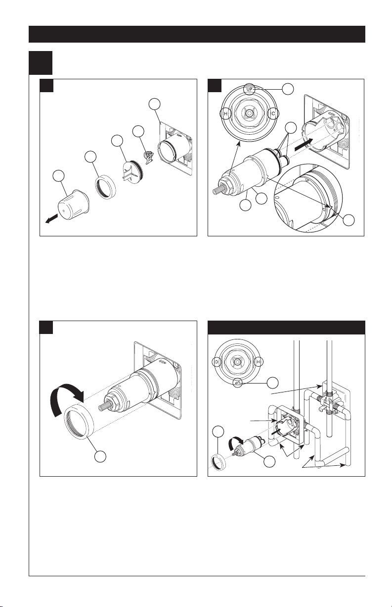
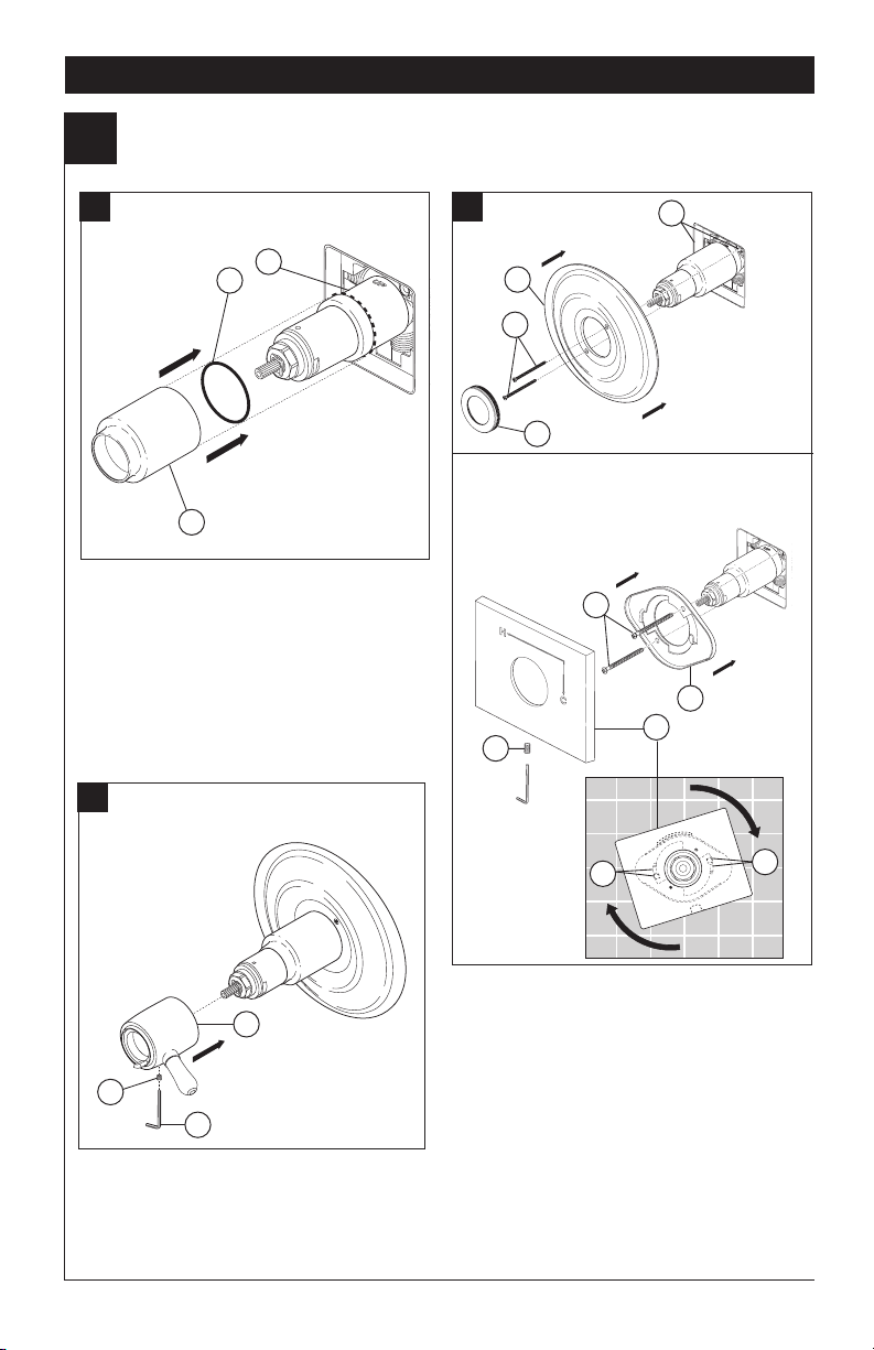
Cartridge Installation
1
Installation
A. B.
4
5
3
2
1
Turn off water supplies. Remove cover (1),
bonnet nut (2) and test cap (3) from the body.
Place a bucket or small container over the front
of the valve body and slowly open the water
supplies to ush any debris from the supply
lines before installing the cartridge. Turn the
water suplies back off. If this is not a thin wall
mounting, the entire plasterguard (4) may be
removed. If screen (5) is in place, remove
before installing cartridge.
Rotate the cartridge (1) so the word “UP” (2)
appears on the top. The “H” must be on the
hot side and the “C” must be on the cold side.
Add silicone lube to the three o-rings (3) shown
above to make the cartridge easier to install and
remove from the valve body. Insert cartridge
into valve body as shown. Ensure the keys on
the body are fully engaged with the slots in the
body (4).
C.
2
3
4
1
Back to back Installation
4
Slide bonnet nut (1) over the cartridge and
thread onto the body. Hand tighten securely.
2
Normal Installation
(changes not required)
Reverse
Installation
3
1
For the exceptions of back to back or reverse
installations (hot on right and cold on left) only:
Rotate cartridge (1) so “H” is on the hot side
and “C” is on the cold side and the word “UP”
(2) appears on the bottom. Add silicone lube
to the three o-rings shown above to make the
cartridge easier to install and remove from the
valve body. Install the cartridge making sure
that the keys are fully engaged with the slot in
the brass body (see step B). Slide bonnet nut
(3) over the cartridge and thread onto the body.
Hand tighten securely.
3
Clod
1
Hot
68883 Rev. J
Page 4
Installation
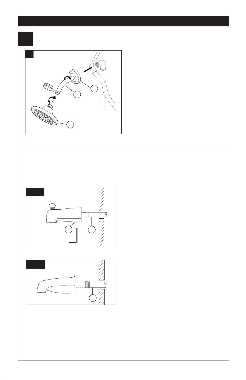
Showerhead and Tub Spout Installation
2
A.
2
1
3
FOR TUB SPOUT INSTALLATION:
Refer to the installation instructions supplied with your spout. Do not connect deck mount spouts to in-wall
valves. Do not use hand showers connected in lieu of a tub spout to a tub/shower valve. Do not use PEX
tubing for tub spout drop.
FOR SHOWERHEAD INSTALLATION:
Apply plumber tape to pipe threads on both ends
of the shower arm (1). To prevent damage to nish
on shower arm, insert wall end of shower arm into
shower ange (2) before screwing arm into riser
connection.
Thread showerhead (3) onto shower arm. Do not
overtighten showerhead.
B-1
B-2
68883 Rev. J
Slip-On Installation
The copper tube (1) must be 1/2” nominal copper.
Important: If it is necessary to cut the copper tube,
2
1
1
the end must be chamfered free of burrs to prevent
cutting or nicking O-ring inside the spout. Slide
spout over copper tube ush with the nished tub
or wall surface. Tighten set screw (2), but do not
overtighten.
Iron Pipe Installation
Install threaded pipe nipple (1) to extend past
nished wall. Apply plumber tape to threads on
pipe nipple and screw on tub spout.
4
Page 5
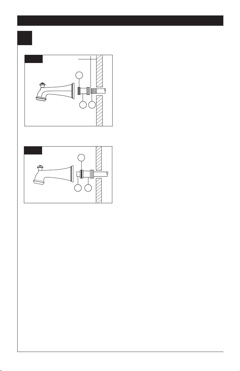
Showerhead and Tub Spout Installation
2
Installation
B-3
B-4
1/2" to 1 1/4"
(13 mm to 32 mm)
3
1 2
1
3 2
Iron Pipe Installation
Installation of easy-on universal tub spout
Install pipe nipple so that end of nipple projects out
from nished wall surface 1/2" to 1 1/4" (13 mm to
32 mm).
Apply plumber tape or pipe dope to pipe threads.
Hand tighten adapter (1) onto pipe nipple (2).
Finish tightening with standard pipe wrench until
a positive seal is implemented. Take care not
to damage O-Ring (3) groove. Back of adapter
(1) must not project more than 1" (25 mm) from
nished wall surface.
Hand tighten tub spout onto adapter (1) taking care
not to damage the O-Ring (3).
Copper Sweat Installation
Remove O-ring (1) from adapter (2). Solder
adapter to tube taking care to keep solder away
from O-ring groove. CAUTION: NO SOLDER
PERMITTED ON OUTSIDE DIAMETER OF
ADAPTER ADJACENT TO O-RING GROOVE. Cut
off tube (3) and replace O-ring on groove of brass
adapter. Thread tub/spout onto adapter, taking
care not to damage O-ring, and hand tighten until
spout is rmly against nished wall and all slack is
taken up behind wall.
5
68883 Rev. J
Page 6
Installation
Valve Trim Installation
3
A.
2
1
3
Slide O-ring (1) over cartridge and the
bonnet nut (2). The O-ring, which acts as
a spacer to steady the sleeve, should rest
behind the bonnet nut. Slide the sleeve (3)
over the cartridge, body and O-ring.
Ensure sleeve is properly positioned over
the front of cartridge.
C.
B.
1
3
4
2
Escutcheon Installation for
Models T17T053, T17T253, T17T453
T17T067, T17T267 & T17T467.
6
5
9
7
1
3
2
Install volume control handle (1) with lever
to the right, using an Allen wrench (2) to
secure with the set screw (3).
68883 Rev. J
8
Secure the escutcheon (1) to the bracket
(2) with the 2 screws provided (3). Do not
overtighten escutcheon screws.
If you are installing the Cassidy models
T17T097, T17T297 & T17T497:
Thread the cover (4) onto the escutcheon (1).
For models T17T053, T17T253, T17T453
T17T067, T17T267 & T17T467:
Install bracket (5) over the cartridge body
using the 2 screws provided (6). Install
escutcheon (7) by placing it over the bracket
as shown and rotating it to lock the tabs (8).
Secure the escutcheon to the bracket using
set screw (9).
6
8
Page 7
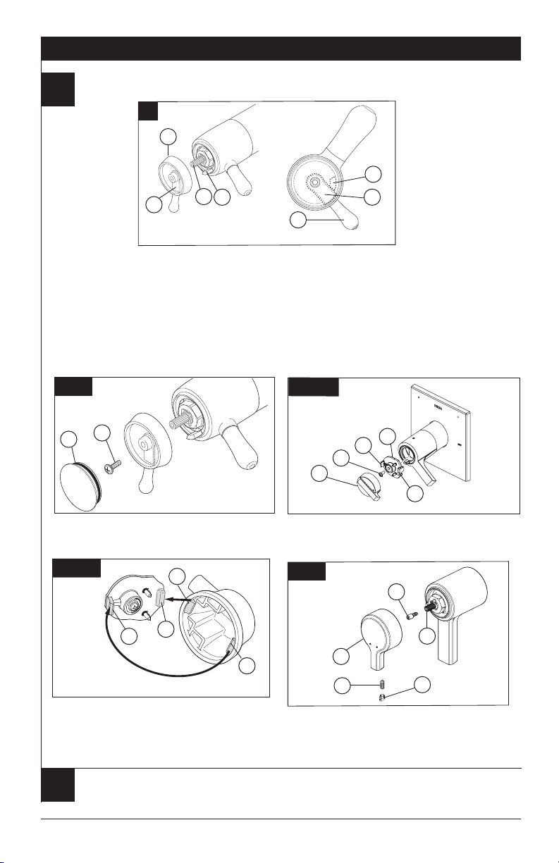
Installation and Adjustment of the Temperature Knob
Failure to do so may cause injury.
4
A.
1
2
3
4
1
Installation
4
3
A. Adjust temperature limit stop!
Turn on water supplies; LET THE WATER RUN AT
BOTH FULL HOT AND FULL COLD TO ENSURE
THE WATER IS RUNNING AS HOT/COLD AS
POSSIBLE. Place a thermometer in a plastic tumbler,
and hold the tumbler in the water stream. Place the
temperature knob (1) onto the splines (2), then rotate
the temperature knob counter-clockwise until you
achieve your maximum desired temperature from the
outlet (not more than 120° or the lower temperature
mandated by your local plumbing code).
B-1.
1
2
Secure the temperature knob using screw (1) and
place cap (2) on knob.
B-2B.
4
Snap temperature control cover over temperature
control knob by rst aligning smaller tab (1) on cover
with receiving slot (2) on temperature knob. Swing
larger tab (3) to engage with snap feature (4). Note:
If dis-assembly is required, reverse this motion,
disengaging larger tab (3) from snap feature (4) rst.
Potential scald or thermal shock injury could result due to cross ow if outlet at the
shower is blocked or restricted (e.g., pause control on showerhead). Be sure to point
5
showerhead away from you when re-starting ow or install inlet check valves on both
supply lines to prevent possible injury.
1
2
3
If max temperature is not achieved before limit stop
(3) on temperature knob (1) meets the limit stop (4) on
the volume control handle. Remove the temperature
control knob (1) from splines (2). Rotate temperature
control knob (1) clockwise. Place temperature control
knob (1) back onto splines (2) and continue to rotate
counter-clockwise until maximum desired temperature
is achieved.Remove the temperature knob (1) and
replace onto the splines (2), making sure that the
temperature knob limit stop (3) hits against the volume
handle limit stop (4) as shown.
B-2A.
1
5
2
4
Secure temperature control knob (1) with screw (2).
Hook (3) front of temperature control cover (4) onto
knob (1) before engaging rear snap (5).
B-3.
1
3
4
Attach spacer screw (1) to valve stem (2). Slide
temperature control handle (3) into place over spacer
screw (1) and secure using set screw (4). Cover with
decorative button (5).
7
3
2
5
68883 Rev. J
Page 8
Cleaning and Care
Care should be given to the cleaning of
this product. Although its nish is extremely
durable, it can be damaged by harsh
abrasives or polish. To clean, simply wipe
gently with a damp cloth and blot dry with a
soft towel.
Maintenance
Cannot receive more than a trickle of water:
Both hot and cold supply lines must be pressurized.
If only one side is pressurized, the system will not
allow adequate ow of water.
Faucet leaks from showerhead:
Remove the showerhead then turn the water on
and off to verify if the cartridge is leaking or the
showerhead is draining slowly (the showerhead may
need to be cleaned if water drains slowly).
If leak persists -SHUT OFF WATER SUPPLIES
Replace cartridge assembly - RP47201.
Unable to set or maintain mixed water temperature:
SHUT OFF WATER SUPPLIES. Remove handle
assembly, trim sleeve, and bonnet nut. Check to make
sure the “H” marking on the cartridge aligns with the
hot inlet and the “C” marking on the cartridge aligns
with the cold inlet to the valve body The thermostatic
cartridge cannot function if hot and cold inlets are
reversed.
®
Warning: Scrubbing Bubbles
Cleaner and Lysol
®
Basin Tub and Tile
Bathroom
Cleaner must not be used on the clear knob
handles and levers. Use of these cleaners
can result in cracked or severely damaged
handles. If overspray gets onto the handles,
immediately wipe them dry with a soft cotton
cloth.
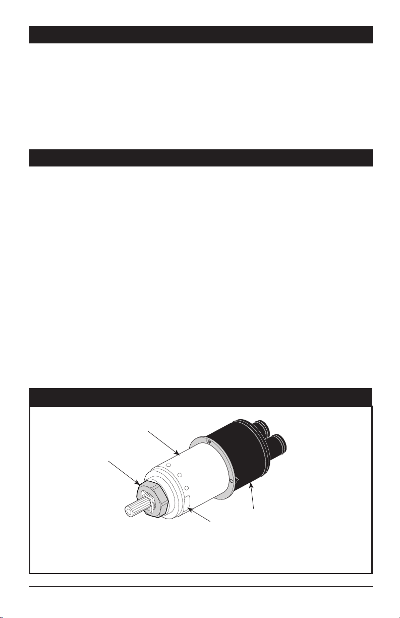
Low ow:
Low ow may be caused by clogged screens within
the thermostatic cartridge. To clean the hot and cold
screens in the cartridge, follow the steps below:
1. SHUT OFF WATER SUPPLIES.
2. Remove the handle assembly.
3. Unscrew the hex shaped portion of the cartridge
from the brass section of the cartridge. the brass
section must be held securely by the ats while
the hex is rotated counter-clockwise. Failure to
secure the brass section while rotating the
hex can result in damage to the cartridge.
(See illustration below)
4. Carefully clean any debris from the screens
under running water. If the debris is difcult to
remove then soak the screens overnight in a
50% water and 50% vinegar solution.
5. Reassemble the cartridge.
6. Replace the handle.
7 Turn the water back on.
8. Reset the limit stop before using the valve.
17T
68883 Rev. J
Cartridge Summary Reference Sheet
Brass
Hex shaped
portion
Black
Flats
Order RP47201 to
Replace Cartridge.
8
Page 9
Instrucciones para la
Instalación del Accesorio
para Válvulas MultiChoice
Manual para los
Propietarios
17T Series
Escriba aquí el número del modelo comprado.
Usted puede necesitar
L
O
F
N
E
T
Contenido:
Garantías ................................................................................. Page 2
Instrucciones de Instalación .................................................... Pages 3 - 7
Limpieza y Cuidado de su Liave .............................................. Page 8
Mantenimiento .......................................................................... Page 8
Hoja resumen de referencia para el cartucho .......................... Page 8
Para ordenar las piezas de repuesto, visítenos en www.deltafaucet.com
ADVERTENCIA: El instalador debe apostar este
systema/divisa para garantizar temperatura maximo
y seguro. Cualqueir cambio en el ajuste puede subir
la temperatura del agua de descarga sobre el límite
considerado seguro y puede resultar en quemaduras
de agua caliente.
AVISO PARA EL INSTALADOR: PRECAUCIÓN
– Como instalador de esta válvula, es su
responsabilidad de INSTALAR Y AJUSTAR
apropiadamente esta válvula como se describe
en las instrucciones, por lo tanto, debe haber
una persona para hacer los ajustes necesarios
del pomo para la temperatura en el momento
que se haga la instalación y pueda necesitar
ajustes adicionales por los cambios estacionales
de la temperatura del agua. USTED DEBE
informarle al dueño/usuario sobre este requisito
siguiendo las instrucciones. Si usted o el dueño/
usuario no están seguros como hacer estos
ajustes apropiadamente, por favor reérase al
Página 7 y si todavía no está seguro, llámenos al
1-800-345-DELTA.
Después de hacer la instalación y el ajuste, usted
puede agregarle a la etiqueta de aviso proporcionada,
su nombre, el nombre de la compañía y la fecha
cuando ajustó pomo para la tempe raturay aplicar
o jar la etiqueta al dorso de la puerta del gabinete
más cercano y la etiqueta de aviso al calentador de
agua. Deje la Hoja de Instrucciones para referencia
del dueño/usuario.ADVERTENCIA: Esta válvula
de presión balanceada y termostática está
diseñada para minimizar los efectos de los
cambios de temperatura de agua por causa de
los cambios de presión en el agua de entrada,
comúnmente causados por lavadoras de platos,
lavadoras de ropa, inodoros, y otros aparatos
por el estilo. Puede no proporcionar protección
de quemaduras de agua caliente cuando hay
alguna falla de otros aparatos para el control
de temperatura en otro sitio en el sistema de
plomería. También no proporcionará protección
si el pomo para el ajuste de la temperatura
no está apropiadamente jo o si cambia la
temperatura del agua caliente después de
hacer los ajustes o si los cambios del agua
de entrada son por los cambios estacionales.
ADVERTENCIA: No instale un aparato de corte
o cierre en cualquiera de las tomas de esta
válvula. Cuando este tipo de aparato cierra el
ujo de agua, puede hacer fallar la habilidad de
la válvula de balancear las presiones del agua
caliente y fría.
®
05/02/2018
1
68883 Rev. J
Page 10

Garantía Limitada De Por Vida de la Llave y su Acabado
Piezas y acabado
Todas las piezas (excepto las piezas electrónicas y las
pilas) y los acabados de esta llave de agua Delta
están garantizados al consumidor comprador original de
estar libres de defectos en material y fabricación
durante el tiempo que el comprador original posea la
vivienda en la que la llave de agua fue originalmente
instalada o, para los consumidores comerciales, durante
5 años a partir de la fecha de compra.
Componentes electrónicos y pilas (si aplicable)
Todas las piezas (salvo las pilas), si hay, de esta llave
de agua Delta
comprador original de estar libres de defectos en
materiales y fabricación durante 5 años a partir de la
fecha de compra o, para los usuarios comerciales, por
un año a partir de la fecha de compra. No se garantizan
las pilas.
Delta Faucet Company reemplazará, SIN CARGO,
durante el período de garantía aplicable, cualquier pieza
o acabado que pruebe tener defectos de material y/o
fabricación bajo la instalación, uso y servicio normal. Si
la reparación o su reemplazo no es práctico, Delta
Faucet Company tiene la opción de reembolsarle su
dinero por la cantidad del precio de compra a cambio de
la devolución del producto. Estos son sus únicos
recursos.
Delta Faucet Company recomienda que use los
servicios de un plomero profesional para todas las
instalaciones y reparaciones. También le recomendamos
que utilice sólo las piezas de repuesto
originales de Delta
Delta Faucet Company no será responsable por
cualquier daño a la llave de agua que resulte del
mal uso, abuso, negligencia o mala instalación o
mantenimiento o reparación incorrecta, incluyendo
el no seguir los cuidados aplicables y las instrucciones
de limpieza.
Las piezas de repuesto se pueden obtener llamando al
número correspondiente más abajo, o
escribiendo a:
®
están garantizadas al consumidor
®
.
®
En los Estados Unidos y México:
Delta Faucet Company
Product Service
55 E. 111th Street
Indianapolis, IN 46280
1 800 345 DELTA (3358)
customerservice@deltafaucet.com
En Canadá:
Masco Canada Limited, Plumbing Group
Technical Service Centre
350 South Edgeware Road
St. Thomas, Ontario, Canada N5P 4L1
1 800 345 DELTA (3358)
customerservice@mascocanada.com
La prueba de compra (recibo original) del comprador
original debe ser disponible a Delta Faucet Company para
todos los reclamos a menos que el comprador haya
registrado el producto con Delta Faucet Company. Esta
garantía le aplica sólo a las llaves de agua de Delta
fabricadas después del 1 de enero 1995 e instaladas en los
Estados Unidos de América, Canadá y México.
DELTA FAUCET COMPANY NO SE HACE RESPONSABLE
POR CUALQUIER DAÑO ESPECIAL, INCIDENTAL
O CONSECUENTE (INCLUYENDO LOS GASTOS DE
MANO DE OBRA) POR EL INCUMPLIMIENTO DE
CUALQUIER GARANTÍA EXPRESA O IMPLÍCITA DE LA
LLAVE DE AGUA. Algunos estados/provincias no permiten la
exclusión o limitación de daños especiales, incidentales o
consecuentes, por lo que estas limitaciones y exclusiones
pueden no aplicarle a usted. Esta garantía le otorga
derechos legales. Usted también puede tener otros
derechos que varían de estado/provincia a estado/provincia.
Esta es la garantía exclusiva por escrito de Delta Faucet
Company y la garantía no es transferible.
Si usted tiene alguna pregunta o inquietud acerca de
nuestra garantía, por favor, vea nuestra sección de
preguntas frecuentes FAQ sobre la garantía en
www.deltafaucet.com, también puede enviarnos un correo
electrónico a customerservice@deltafaucet.com o llámenos
al número que le corresponda anteriormente incluido.
Garantia Limitada de Delta HDF
Todas las piezas de la llave Delta HDF están
garantizadas al dueño original de estar libres de
defectos en materiales y en la mano de obra por un
período de cinco (5) años. Esta garantía se hace al
dueño original y será efectiva el día de la compra como
se ve en el recibo de compra.
Delta reemplazará, LIBRE DE CARGO, durante el
período de la garantía, cualquier pieza que resulte
defectuosa en materiales y/o en la mano de obra bajo
instalación, uso y servicio normal. Las piezas de
repuesto pueden ser obtenidas de su comerciante o
distribuidor local que se encuentran en la guía telefónica
o si usted devuelve la pieza con el recibo de compra
a nuestra fabrica, Y LOS CARGOS DE TRANSPORTE
PAGADOS CON ANTELACION, a la dirección dada.
ESTA GARANTIA ES LA UNICA GARANTIA EXPRESA
DE DELTA. CUALQUIER RECLAMO HECHO BAJO
ESTA GARANTIA TIENE QUE SER HECHO DURANTE
EL PERIODO DE CINCO AÑOS A QUE SE REFIERE
ARRIBA. CUALQUIER GARANTIA IMPLICITA,
INCLUYENDO LA GARANTIA IMPLICITA DE
COMERCIALIZACION O CONVENIENCIA PARA UN
PROPOSITO PARTICULAR, SON LIMITADOS EN
www.deltafaucet.com
68883 Rev. J
DURACION A LA DURACION DE ESTA GARANTIA.
LOS CARGOS PARA LA MANO DE OBRA Y/O DAÑOS
INCURRIDOS EN LA INSTALACION, REPARACION O
REEMPLAZO, ASI COMO LOS DAÑOS INCIDENTALES
O CONSECUENTES CONECTADOS CON
ELLOS SON EXCLUIDOS Y NO SERAN PAGADOS
POR DELTA.
Algunos estados no permiten limitaciones al tiempo que
dura la garantía implícita, o la exclusión o limitación de
los daños incidentales o consecuentes, así que la
limitación o exclusión expresada arriba puede no ser
aplicable a usted.
Esta garantía le da a usted derechos legales especícos
y usted puede también tener otros derechos que varían
de estado a estado.
Esta garantía es nula por cualquier daño a esta llave
que sea el resultado del mal uso, abuso, negligencia,
accidente, instalación impropia, cualquier uso en
violación de las instrucciones suministradas por
nosotros o cualquier uso de piezas de repuesto que no
sean piezas genuinas Delta.
© 2018 Masco Corporación de Indiana
2
Page 11

Instalación del Cartucho
1
A.
Instalación
B.
4
2
5
3
2
1
Cierre los suministros de agua. Retire la cubierta (1),
la tuerca tapa (2) y la tapa de prueba (3) del cuerpo.
Coloque un balde o recipiente pequeño en la parte del
frente del cuerpo de la válvula y lentamente abra el
suministro de agua para eliminar cualquier residuo de
las líneas de agua antes de instalar el cartucho. Cierre,
de nuevo, el suministro de agua. Si no es para una
instalación en pared delgada, puede quitar el protector
de yeso completo (4). Si la rejilla o colador (5) está en
su lugar, quítela antes de instalar el cartucho.
C.
3
4
1
4
Gire el cartucho (1) de manera que la palabra “UP”
(2) aparezca en la parte superior. La “H” debe
estar en el lado caliente y la “C” debe estar en el
lado frío. Agregue lubricante de silicón a las tres
juntas tóricas (3) como se muestra más arriba para
facilitar la instalación y la retirada del cartucho
del cuerpo de la válvula. Inserte el cartucho en el
cuerpo de la válvula como se muestra. Asegúrese
que las llaves en el cuerpo están totalmente
engranadas en las ranuras en el cuerpo (4).
Instalación de Espalda a Espalda
2
Instalación Normal
(No serequerá cambios)
Instalación
Invertido
3
Deslice la tuerca tapa (1) sobre el cartucho y enrosque
en el cuerpo de la válvula. Apriete a mano bien.
1
Solo para las excepciones en instalaciones de dorso con
dorso o en reverso (el agua calienten la derecha y fría en la
izquierda): Gire el cartucho (1) de manera que la “H” está
en el lado caliente y la “C” está en el lado frío y la palabra
“UP” (2) aparece en la parte inferior. Agregue lubricante de
silicón a las tres juntas tóricas (3) como se muestra más
arriba para facilitar la instalación y la retirada del cartucho
del cuerpo de la válvula. Inserte el cartucho en el cuerpo
de la válvula como se muestra. Asegúrese que las llaves
en el cuerpo están totalmente engranadas en las ranuras
en el cuerpo de bronce (vea la página B). Deslice la tuerca
tapa (3) sobre el cartucho y enrosque en el cuerpo. Apriete
a mano bien.
3
1
Fría
Caliente
68883 Rev. J
Page 12

Instalación
Instalación de la Cabeza de la Regadera y el Surtidor de la Bañera
2
A.
2
1
3
PARA LA INSTALACIÓN DEL SURTIDOR DE LA BAÑERA:
Reérase a las instrucciones para la instalación suministradas con su surtidor. No conecte los surtidores
para las instalaciones en las supercies horizontales en las válvulas dentro de las paredes. No use las
regaderas de mano en vez de un surtidor de bañera conectado a una válvula de bañera/regadera. No use
tubería PEX como tubería entre la válvula y el surtidor de la bañera.
INSTALACIÓN DE LA REGADERA /
DUCHA:
Aplique cinta para plomero a las roscas en ambos
extremos del brazo de la regadera (1). Para
prevenir daño al acabado del brazo de la regadera,
inserte el extremo de la pared del brazo de la
regadera en la brida de ésta (2) antes de enroscar
el brazo en la conexión a la tubería interior.
Enrosque la regadera (3) en el brazo de la
regadera. No apriete la regadera demasiado.
B-1
B-2
Instalación deslizable
El tubo de cobre (1) debe ser de1/2" de cobre
nominal. Importante: Si es necesario cortar el tubo
2
1
1
de cobre, el extremo debe biselarse que quede
libre de rebabas para prevenir cortar o mellar el
aro O dentro del tubo de cobre. Deslice el surtidor
sobre el tubo de cobre al ras con la bañera o la
supercie de la pared acabada. Apriete el tornillo
de ajuste (2), pero no apriete demasiado.
Instalación de la tubería de Hierro
IInstale una entrerrosca de tubo enroscado de
1/2” (13 mm) (1) para extenderse por delante de
la pared acabada. Aplique cinta para plomero a
las roscas en la entrerrosca de tubo y atornille el
surtidor de la bañera.
68883 Rev. J
4
Page 13

Instalación
Instalación de la Cabeza de la Regadera y el Surtidor de la Bañera
2
B-3
B-4
1/2" a 1 1/4"
(13 mm a 32 mm)
3
1 2
1
3 2
Instalación del tubo de hierro
Instalación del tubo de salida de agua del
easy-on universal para bañeras
Instale la entrerrosca del tubo de manera que
el extremo de ésta sobresalga de la pared
acabada 1/2" a 1 1/4" (13 mm a 32 mm). Aplique
cinta para plomero o compuesto para tubos a
las roscas del tubo. Apriete a mano el adaptador
(1) a la entrerrosca del tubo (2). Termine
apretando con una llave de tubos estándar
hasta que el sello positivo se implemente. Tenga
cuidado de no dañar la muesca del anillo-O (3).
La parte posterior del adaptador (1) no debe
sobresalirse más de 1" (25 mm) de la supercie
de la pared acabada. Apriete a mano el tubo de
salida de agua de la bañera al adaptador (1)
teniendo cuidado de no dañar el anillo - O (3).
Instalación de Soldadura de Cobre
Quite el aro O (1) del adaptador (2). Suelde el
adaptador al tubo asegurando de mantener la
soldadura lejos de las muesca del aro O. AVISO:
NO SE PERMITE SOLDAR EN EL DIAMETRO
EXTERIOR DEL ADAPTADOR ADJUNTO A LA
MUESCA DEL ARO O. Corte el tubo (3) y coloque
otra vez el aro O en la muesca del adaptador de
latón. Atornille la bañera/surtidor al adaptador,
asegurando no dañar el aro O, y apriete a mano
bien hasta que el surtidor quede rmemente contra
la pared acabada y no quede ojo detrás de la
pared.
5
68883 Rev. J
Page 14

Instalación Final
3
Instalación
A.
2
1
3
Deslice el aro O (1) sobre el cartucho y la
tuerca tapa (2). El aro O, el cual funciona
como un separador para estabilizar la
manga, debe quedar apoyado en la
tuerca tapa. Deslice la manga (3) sobre el
cartucho, el cuerpo de la pieza y el aro O.
C.
B.
1
3
4
2
La instalación de la roseta para los
modelos T17T053, T17T253, T17T453
T17T067, T17T267 y T17T467.
6
5
9
7
1
3
2
Instale la manija de control de volumen (1)
con la palanca a la derecha, usando una
llave Allen (2) de asegurar con el tornillo de
presión (3).
68883 Rev. J
8
Fije la roseta con oricio (1) al soporte (2)
usando los 2 tornillos suministrados (3). No
apriete demasiado los tornillos de la roseta.
Si está instalando the Cassidy Modelos
T17T097, T17T297 y T17T497: Gira la tapa (4)
en la cubierta de oricio (1).
Para los modelos T17T053, T17T253,
T17T453, T17T067, T17T267 y T17T467:
Instale el soporte (5) sobre el cuerpo del
cartucho usando los 2 tornillos incluidos (6).
Instale la chapa de base (7) colocándola sobre
el soporte como se muestra y girándola para que
encaje en las muescas (8). Fije la chapa de base
al soporte usando el tornillo de ajuste (9).
6
8
Page 15

Instalación
Instalación y Ajuste del Pomo de Temperatura
El no hacerlo puede causar lesión.
4
A.
1
2
3
4
4
3
1
A: ¡Ajuste el tope del límite de temperatura!
Abra los suministros de agua; DEJE QUE CORRA EL
AGUA CALIENTE Y FRÍA TOTALMENTE ABIERTA
PARA ASEGURAR QUE EL AGUA ESTÁ FLUYENDO
LO MÁS CALIENTE/FRÍA POSIBLE. Coloque un
termómetro en un vaso plástico, y sostenga el vaso
bajo un chorro de agua. Coloque la perilla de la
temperatura (1) en las ranuras (2), y gire la perilla de
la temperatura hacia la izquierda hasta alcanzar su
máxima temperatura deseada de salida de agua (no
más de 120° o la temperatura más baja autorizada por
su código de plomería local). Si la temperatura máxima
no se alcanza antes de llegar al tope del límite (3) en el
B-1.
1
2
Fije el pomo de la temperatura usando un tornillo (1)
y coloque la tapa (2) en el pomo.
B-2B.
1
control de la temperatura (1) donde tropieza con
el tope del límite rotacional (4) en la manija del
control de volumen. Retire la perilla del control de
temperatura (1) de las ranuras (2). Gire la perilla del
control de temperatura (1) hacia la derecha. Coloque
la perilla del control de temperatura (1) otra vez en
las ranuras (2) y continue girando hacia la izquierda
hasta que alcanza la temperatura máxima deseada.
Quite el pomo de la temperatura (1) y colóquela otra
vez en las ranuras (2), asegurándose que el pomo
del tope del límitede la temperatura (3) pegue contra
la manija del tope del límite del volumen (4) como se
muestra.
B-2A.
1
5
2
4
3
Fije la perilla para el control de la temperatura (1) con
un tornillo (2) .Gancho (3) delantero coloque la perilla
para el control de couverture(4) encima de perilla (1)
antes de la participación parte trasera instantánea (5).
B-3.
1
2
4
3
Coloque a presión la tapa del control de temperatura
sobre el pomo del control de temperatura alineando
primero la lengüeta más pequeña (1) con la muesca
para encajar en la cubierta (2) ubicada en el pomo de
temperatura. Gire la lengúeta más grande (3) para
que encaje con el mecanismo de presión (4). Nota:
Si requiere desarmar, repita estos pasos en reverso,
desencajando primero la lengúeta más grande (3) del
mecanismo de presión (4).
Si la ducha está bloqueado o restringido, puede resultar posiblemente quemadura o lesion (por
ejemplo, cesa a contral la ducha). Asegúrese salir ducha cuando encender otra vez el flujo o
5
instalar válvulas para evitar lesion posible.
Fije la perilla para el control de la temperatura (1)
con un tornillo (2) .Gancho (3) delantero coloque
la perilla para el control de couverture (4) encima
de perilla (1) antes de la participación parte trasera
instantánea (5).
7
3
4
2
5
68883 Rev. J
Page 16

Limpieza y Cuidado de su Llave
Tenga cuidado al ir a limpiar este producto.
Aunque su acabado es sumamente durable,
puede ser afectado por agentes de limpieza
o para pulir abrasivos. Para limpiar su llave,
simplemente frótela con un trapo húmedo y
luego séquela con una toalla suave.
Mantenimiento
No recibe más de un goteo de agua:
Ambas líneas de suministro de agua, la caliente y
la fría, deben estar presurizadas. Si sólo un lado
está presurizado, el sistema no permitirá el ujo
adecuado de agua.
Si la llave tiene fugas desde la regadera /
ducha:Retire la cabeza de la regadera luego, cierre
y abra el ujo de agua y verique si el cartucho tiene
alguna fuga o si la regadera está escurriéndose
lentamente (si el agua drena lentamente, puede ser
necesario limpiar la cabeza de la regadera).
Si la ltración o fuga persiste -CIERRE LOS
SUMINISTROS DE AGUA Cambie el cartucho -
RP47201.
No se puede establecer o mantener la temperatura
del agua mixta:
CIERRE LOS SUMINISTROS DE AGUA. Retire el
ensamble de la manija, la manga, y la tuerca tapa.
Asegúrese que la marca “H” en el cartucho quede
alineada con la entrada de agua caliente y la marca
“C”, en el cartucho, quede alineada con la entrada
del agua fría al cuerpo de la válvula. El cartucho
termostático no puede funcionar si las entradas de
¡
ADVERTENCIA! No se puede usar
SCRUBBING BUBBLES® BATHROOM
CLEANER o LYSOL® BASIN TUB AND TILE
CLEANER en las manijas transparentes. El
uso de estos productos pueden resultar en
manijas rajados o severamente dañados. Si
estos productos caen sobre la manija, séquelo
inmediatamente con una toalla de algodón
suave.
agua fría y caliente están invertidas.
Flujo bajo: el ujo bajo puede ser por causa de
obstrucciones en los ltros dentro del cartucho
termostático. Para limpiar las rejillas o ltros del agua
caliente y fría en el cartucho, siga los siguientes pasos:
1. CIERRE LOS SUMINISTROS DE AGUA.
2. Retire el ensamble de la manija.
3. Desatornille la porción en forma hexagonal del
cartucho de la sección de bronce del cartucho.
La sección de bronce debe mantenerse ja por los
cortados planos mientras que la sección hexagonal
se gira hacia la izquierda. Si no ja la sección de
bronce mientras que gira la parte hexagonal puede
resultar en daño al cartucho.
(Vea la ilustración a continuación)
4. Limpie cuidadosamente los residuos de los
ltros bajo el chorro de agua. Si los residuos
son difíciles de eliminar, entonces deje los
ltros remojando durante la noche en una
solución del 50% de agua y 50% de vinagre.
5. Vuela a ensamblar el cartucho.
6. Vuelva a colocar la manija.
7 Abra el ujo de agua otra vez.
8. Restablezca el tope del límite antes de
utilizar la válvula.
Hoja resumen de referencia para el cartucho
17T
68883 Rev. J
Bronce
Porción en
forma hex
Negro
Cortados
planos
Ordene el Repuesto RP47201
para cambiar el cartucho.
8
Page 17

Instructions d’installation
Finition de la soupape
MultiChoice
®
Guide d’utilisation
17T Séries
Inscrivez le numéro de modèle ici.
Articles dont vous pouvez avoir besoin:
L
O
F
N
E
T
Table des matières
Garanties .................................................................................. Page 2
Instructions d’installation .......................................................... Pages 3 - 7
Instructions de nettoyage .......................................................... Page 8
Maintenance .............................................................................. Page 8
Fiche de référence sommaire de la cartouche .......................... Page 8
Pour commander des pièces de rechange, visitez www.deltafaucet.com
ATTENTION: L’installateur doit régler l’appareil
pour que la température maximale de l’eau chaude
soit sans danger. Toute modication des réglage
peut entraîner une élévation de la température à
la sorite du robinet au delà de la température sans
danger et pourrait causer un échaudage.
AVIS À L’INSTALLATEUR: ATTENTION! –
En qualité d’installateur, vous êtes tenu
d’INSTALLER et de RÉGLER ce robinet
conformément aux instructions. Ce robinet ne
s’adapte pas automatiquement aux uctuations
de la température de l’eau d’alimentation.
Par conséquent, il faut régler la le bouton de
température au moment de l’installation et
il peut être nécessaire de faire de nouveaux
réglages par la suite en raison des uctuations
saisonnières de la température de l’eau. VOUS
DEVEZ informer le propriétaire ou l’utilisateur
de cette exigence. En cas de doute quant à
la marche à suivre pour faire ces réglages,
veuillez consulter page 7 si un doute persiste,
et si cette incertitude persiste, appelez-nous au
1-800-345-DELTA.
Après avoir terminé l’installation et le réglage, vous
devez inscrire, sur l’étiquette de mise en garde
fournie, votre nom, le nom de votre entreprise et
la date à laquelle vous avez réglé la le bouton
de température, puis xer l’étiquette à l’endos de
la porte de la coiffeuse. Vous devez également
xerl’étiquette d’avertissement au chauffe-eau.
Veuillez laisser ce feuillet d’instructions au
propriétaire ou à l’utilisateur pour qu’il puisse
le consulter au besoin. MISE EN GARDE –
Ce robinet thermostatique à équilibrage de
pression pour baignoire est conçu pour limiter
les effets des uctuations de température de
l’eau causées par les variations de la pression
d’alimentation attribuables au fonctionnement
d’un lave-vaisselle, d’une machine à laver,
d’un cabinet d’aisances ou d’un autre appareil
qui consomme de l’eau. Il peut ne pas
protéger l’utilisateur contre l’échaudage en
cas de défectuosité d’un autre dispositif de
régulation de la température, si le réglage de
la du bouton de température est mauvais, si
la température de l’eau chaude a été modiée
après que les réglages ont été effectués ou si
la température de l’eau d’alimentation a changé
en raison du changement de saison. MISE EN
GARDE – N’installez pas de dispositif d’arrêt
sur une sortie quelconque de ce robinet. En
interrompant l’écoulement de l’eau, ce dispositif
peut empêcher le robinet d’équilibrer les
pressions d’eau chaude et d’eau froide.
05/02/2018
1
68883 Rev. J
Page 18

Garantie à vie limitée des robinets et de leurs nis
Pièces et nis
Toutes les pièces (à l’exception des composants
électroniques et des piles) et tous les nis de ce robinet
®
sont protégés contre les défectuosités du matériau
Delta
et les vices de fabrication par une garantie qui est
consentie au premier acheteur et qui demeure valide tant
que celui-ci demeure propriétaire de la maison dans
laquelle le robinet a été installé. Dans le cas d’une
utilisation commerciale, la garantie est de 5 ans à compter
de la date d’achat.
Composants électroniques et piles (le cas échéant)
Si ce robinet Delta
électroniques, ces composants (à l’exception des piles)
sont protégés contre les défectuosités du matériau et les
vices de fabrication par une garantie consentie au premier
acheteur qui est d’une durée de 5 ans à compter de la
date d’achat. Dans le cas d’une utilisation commerciale, la
garantie est d’un an à compter de la date d’achat. Aucune
garantie ne couvre les piles.
Delta Faucet Company remplacera, GRATUITEMENT,
pendant la période de garantie applicable, toute pièce ou
tout ni qui présentera une défectuosité du matériau et/ou
un vice de fabrication pour autant que le robinet ait été
installé, utilisé et entretenu normalement. S’il est
impossible de réparer ou de remplacer le robinet, Delta
Faucet Company pourra décider de rembourser le prix
d’achat du produit pour autant que celui-ci lui soit retourné.
Il s’agit de vos seuls recours.
Delta Faucet Company recommande de coner
l’installation et la réparation à un plombier professionnel.
Nous vous recommandons également d’utiliser
uniquement des pièces de rechange authentiques Delta
Delta Faucet Company se dégage de toute responsabilité
à l’égard des dommages causés au robinet en raison d’un
mauvais usage, d’un usage abusi f, de la négligence ou de
l’utilisation d’une méthode d’installation, de maintenance
ou de réparation incorrecte ou inadéquate, y compris
les dommages résultant du non-respect des instructions
de nettoyage et d’entretien applicables. Garantie limitée
des robinets Delta
veuillez appeler au numéro applicable ci-dessous ou écrire
à l’adresse applicable ci-dessous.
®
comporte des composants
®
Pour obtenir des pièces de rechange,
Aux États-Unis et au Mexique :
Delta Faucet Company
Product Service
55 E. 111th Street
Indianapolis, IN 46280 St.
1-800-345-DELTA (3358)
customerservice@deltafaucet.com
Au Canada:
Masco Canada Limited, Plumbing Guoup
Thechnical Service Centre
350 South Edgware Roard
Thomas, Ontario, Canada N5P 4L1
1-800-345-DELTA (3358)
customerservice@mascocanada.com
La preuve d’achat (reçu original) du premier acheteur doit
être présentée à Delta Faucet Company pour toutes les
demandes en vertu de la garantie, sauf si le produit a été
enregistré auprès de Delta Faucet Company. La présente
garantie s’applique uniquement aux robinets Delta
fabriqués après le 1er janvier 1995 et installés aux
États-Unis d’Amérique, au Canada et au Mexique.
DELTA FAUCET COMPANY SE DÉGAGE DE TOUTE
RESPONSABILITÉ À L’ÉGARD DES DOMMAGES
PARTICULIERS, CONSÉCUTIFS OU INDIRECTS (Y
COMPRIS LES FRAIS DE MAIN-D’OEUVRE) QUI
POURRAIENT RÉSULTER DE LA VIOLATION D’UNE
GARANTIE IMPLICITE OU EXPLICITE QUELCONQUE
SUR LE ROBINET. Dans les États ou les provinces
où il est interdit de limiter ou d’exclure la responsabilité à
l’égard des dommages particuliers, consécutifs ou
indirects, les limites et les exclusions susmentionnées ne
®
s’appliquent pas.
.
La présente garantie vous donne des droits précis qui
peuvent varier selon l’État ou la province où vous résidez.
La présente garantie écrite est la garantie exclusive offerte
par Delta Faucet Company et elle n’est pas transférable.
Si vous avez des questions ou des préoccupations en ce
qui concerne notre garantie, veuillez consulter la page
Warranty FAQs à www.deltafaucet.com, faire parvenir un
courriel à customerservice@deltafaucet.com ou nous
appeler au numéro applicable.
®
Garantie Limitée sur les Robinets Ultra-Robustes Delta de la Série HDF
Toutes les pièces des robinets ultra-robustes Delta de la
série HDF sont protégées contre les défectuosités du
matériau et les vices de conception par une garantie qui
est consentie au premier acheteur pour une période de
cinq (5) ans. Cette garantie entre en vigueur à compter de
la date d’achat indiquée sur le reçu de l’acheteur.
Pendant la période de garantie, Delta remplacera, SANS
FRAIS, toute pièce présentant une défectuosité du
matériau et (ou) un vice de fabrication pour autant que
l’appareil ait été installé, utilisé et entretenu correctement.
Pour obtenir des pièces de rechange, veuillez
communiquer avec le distributeur ou le concessionnaire de
votre région dont le nom gure dans l’annuaire
téléphonique ou retourner la pièce défectueuse
accompagnée du reçu de l’acheteur à notre usine, PORT
PAYÉ, à l’adresse indiquée. LA PRÉSENTE GARANTIE
EST LA SEULE GARANTIE IMPLICITE OFFERTE PAR
DELTA. TOUTE RÉCLAMATION EN VERTU DE CETTE
GARANTIE DOIT ÊTRE FAITE AU COURS DE LA
PÉRIODE DE CINQ ANS SUSMENTIONNÉE. TOUTE
GARANTIE IMPLICITE, Y COMPRIS LA GARANTIE
IMPLICITE DE QUALITÉ MARCHANDE OU
www.deltafaucet.com
68883 Rev. J
D’ADÉQUATION DU PRODUIT AVEC UN USAGE
PARTICULIER, EST LIMITÉE À LA DURÉE DE LA
PRÉSENTE GARANTIE. LES FRAIS DE
MAIN-D’OEUVRE ET (OU) LES DOMMAGES
PROVOQUÉS AU COURS DE L’INSTALLATION, DE LA
RÉPARATION OU DU REMPLACEMENT D’UN
ÉLÉMENT AINSI QUE LES PERTES OU LES
DOMMAGES INDIRECTS EN RÉSULTANT NE SONT
PAS COUVERTS PAR CETTE GARANTIE.
Là où il est interdit de limiter la durée de la garantie
implicite ou les responsabilités à l’égard des dommages
indirects, les exclusions et les limites susmentionnées ne
s’appliquent pas.
La présente garantie vous donne des droits précis qui
peuvent varier selon votre lieu de résidence.
Les dommages résultant d’une mauvaise utilisation, d’une
utilisation abusive, de la négligence, d’un accident, d’une
mauvaise installation, du non respect de nos instructions
ou de l’utilisation de pièces de rechange autres que des
pièces d’origine Delta ne sont pas couverts par la garantie.
© 2018 Division de Masco Indiana
2
Page 19

Installation de la cartouche.
1
Installation
A. B.
4
5
3
2
1
Fermez les robinets d’arrêt. Enlevez le couvercle
(1), l’écrou-chapeau (2) et le capuchon d’essai (3)
du corps. Placez un seau ou un petit contenant sur
l’avant du corps de soupape et ouvrez lentement les
robinets d’arrêt pour évacuer les corps étrangers de
la tuyauterie avant d’installer la cartouche. Fermez
de nouveau les robinets d’arrêt. Si le corps n’est pas
monté dans un mur mince, vous pouvez enlever le
protecteur (4) au complet. Si le ltre métallique (5)
est en place, enlevez-le avant d’installer la cartouche.
Tournez la cartouche (1) de sorte que le mot « UP
» (2) se trouve sur le dessus. La lettre « H » doit se
trouver du côté eau chaude et la lettre « C », du côté
eau froide. Ajoutez du lubriant à base de silicone aux
trois joints toriques (3) montrés ci-dessus pour faciliter
la pose de la cartouche dans le corps de soupape et
sa dépose. Introduisez la cartouche dans le corps de
la soupape comme le montre la gure. Assurez-vous
que les ergots sont parfaitement engagés dans les
rainures du corps (4).
C.
2
3
4
1
4
Installation dos à dos
Faites glisser l’écrou à portée sphérique (1) sur la
cartouche et vissez-le sur le corps. Serrez à la
main fermement.
2
Installation normale
(Non modiée)
Installation
Inversée
3
1
Dans le cas d’une installation dos à dos ou inversée (eau
chaude à droite et eau froide à gauche) seulement : tournez
la cartouche (1) de sorte que la lettre « H » se trouve du
côté eau chaude, la lettre « C », du côté eau froide et le
mot « UP » (2), sur le dessus. Ajoutez du lubriant à base
de silicone aux trois joints toriques montrés ci-dessus pour
faciliter la pose de la cartouche dans le corps de soupape et
sa dépose. Installez la cartouche en prenant soin d’introduire
les ergots entièrement dans les rainures du corps de laiton
(reportez-vous à l’étape B). Glissez l’écrou-chapeau (3) sur
la cartouche et vissez-le sur le corps. Serrez-le à la main
solidement.
3
1
Eau Froides
Eau Chaude
68883 Rev. J
Page 20

Installation
Installation de la pomme de douche et du bec de baignoire
2
A.
2
1
3
INSTALLATION DU BEC DE BAIGNOIRE:
Consultez les instructions d’installation fournies avec le bec. Ne raccordez pas à une soupape murale à
un bec conçu pour être monté sur une plage. Ne raccordez pas une douche à main à la sortie d’un robinet
de baignoire-douche prévue pour un bec de baignoire. N’utilisez pas de tube PEX pour raccorder le bec.
B-1
2
1
INSTALLATION DE LA POMME DE
DOUCHE: appliquez du ruban de plomero
sur les letages aux deux extrémités
du bras de douche (1). Pour éviter
d’endommager le ni du bras de douche,
introduisez le côté mur de celui-ci dans la
collerette de douche (2) avant de le visser
dans le raccord du tuyau ascendant.
Vissez la pomme de douche (3) sur le
bras de douche.
Évitez de serrer la pomme de douche
excessivement.
Installation d’un bec coulissant
Le tube de cuivre (1) doit avoir un diamètre
nominal de1/2 po. Important : Si vous devez
couper le tube de cuivre, chanfreinez son
extrémité de sorte qu’elle ne risque pas
d’endommager le joint torique à l’intérieur du
bec. Faites glisser le bec sur le tube de cuivre
de sorte qu’il s’appuie contre la surface nie
de la baignoire ou du mur. Serrez la vis de
calage (2), mais prenez garde de la serrer
excessivement.
B-2
68883 Rev. J
Installation à l’aide d’un tuyau de fer
Installez le manchon leté (1) 1/2 po (13
mm) de manière que sa saillie par rapport à
la surface nie du mur. Appliquez du ruban
de plomberie sur les lets du manchon et xez
celui-ci au bec de baignoire en vissant.
1
4
Page 21

Installation
Installation de la pomme de douche et du bec de baignoire
2
B-3
B-4
1/2 po a 1 1/4 po
(13 mm to 32 mm)
3
1 2
1
3 2
Installation sur un tuyau de fer
Installation du bec de baignoire polyvalent
easy-on
Installez le manchon leté de manière qu’il
présente une saillie de 1/2 à 1 1/4 po (13 mm à
32 mm) par rapport à la surface nie du mur.
Appliquez du ruban de plomberie ou du
composé à letage sur les lets. Montez
l’adaptateur (1) sur le manchon (2) et serrezle à la main. Finissez ensuite le serrage à l’aide
d’une clé à tube pour rendre le joint étanche.
Prenez garde d’abîmer le rainure du joint
torique (3). Les dos de l’adaptateur (1) ne doit
pas se trouver à plus de 1 pouce (25 mm) par
rapport à la surface nie du mur.
Montez le bec de baignoire sur l’adaptateur (1)
et serrez-le à la main en prenant soin de ne pas
abîmer le joint torique (3).
Installation à l’aide d’un tuyau de cuivre brasé
QRetirez le joint torique (1) de l’adaptateur (2).
Brasez l’adaptateur au tube en prenant garde
d’échapper du métal d’apport dans la rainure
pour le joint torique. ATTENTION : IL NE
DOIT PAS Y AVOIR DE MÉTAL D’APPORT
SUR LA CIRCONFÉRENCE EXTÉRIEURE
DE L’ADAPTATEUR PRÈS DE LA RAINURE
POUR LE JOINT TORIQUE. Coupez le tube
(3) et remettez le joint torique en place dans
la raInure de l’adaptateur en laiton. Vissez le
bec de baignoire sur l’adaptateur et prenant
garde d’abîmer le joint torique. Serrez le bec
à la main jusqu’à ce qu’il s’appuie solidement
contre la surface nie de la paroi et qu’il
n’y ait plus de jeu derrière le mur.
5
68883 Rev. J
Page 22

Installation des pièces de nition
3
Installation
A.
2
1
3
Faites glisser le joint torique (1) sur la
cartouche et l’écrou à portée sphérique
(2). Le joint sert de pièce d’espacement
et il stabilise le manchon; il doit se trouver
derrière l’écrou à portée sphérique. Faites
glisser le manchon (3) sur la cartouche, le
corps et le joint torique.
C.
B.
1
3
4
2
Installation de la rosace pour les
modèles T17T053, T17T253, T17T453
T17T067, T17T267 et T17T467.
6
5
9
7
1
3
2
Installez la poignée de commande de
volume (1) avec le levier vers la droite,
utilisant une clé Allen (2) de fixer avec la
vis de réglage (3).
68883 Rev. J
8
Fixez la rosace (1) sur le support (2) à l’aide
des 2 vis fournies (3). Prenez garde de serrer
les vis de la rosace excessivement.
Si vous installez Cassidy Modèles T17T097,
T17T297 & T17T497: Enlez le couvercle (4)
sur l'écusson (1).
Pour les modèles T17T053, T17T253,
T17T453, T17T067, T17T267 et T17T467:
Montez la xation (5) sur le corps de la
cartouche à l’aide des 2 vis fournies (6).
Installez la plaque de nition (7) en la plaçant
sur la xation comme le montre la gure et
tournez-la pour bloquer les pattes (8). Fixez la
plaque de nition à la xation à l’aide de la vis
de calage (9).
6
8
Page 23

Installation
Installation et réglage du bouton de température
Il y a risque de blessure si le bouton de température n’est pas réglé.
4
A.
1
4
2
3
Réglez la butée limitatrice de température!
Rétablissez l’alimentation en eau. LAISSEZ COULER
CHAUDE JUSQU’À CE QU’ELLE SOIT AUSSI
CHAUDE QUE POSSIBLE ET FAITES DE MÊME
POUR L’EAU FROIDE. Placez un thermomètre dans
un gobelet en plastique et tenez le gobelet sous le
jet d’eau. Placez le bouton de température (1) sur les
cannelures (2), puis tournez-le dans le sens antihoraire
jusqu’à ce que l’eau soit à la température maximale
voulue (pas plus de 120° ou température plus basse
exigée par le code de plomberie local). Si l'eau n'atteint
pas la température maximale avant que la butée de
température maximale (3) sur le
B-1.
4
1
bouton de température (1) n'atteigne la butée de
température maximale (4) sur la manette de débit,
retirez le bouton de réglage de température (1)
des cannelures (2). Tournez le bouton de réglage
de température (1) dans le sens horaire. Replacez
le bouton de réglage de température (1) sur les
cannelures (2) et continuez de le tourner dans le sens
antihoraire jusqu’à ce que l’eau soit à la température
maximale voulue. Enlevez le bouton de température (1)
et replacez-le sur les cannelures (2) en vous assurant
que la butée limitatrice de température (3) s’appuie
contre la butée de la manette de débit (4) comme le
montre la gure.
B-2A.
3
1
2
Fixez le bouton de température à l’aide de la vis (1)
et placez le capuchon (2) sur le bouton.
B-2B.
1
2
4
Fixez le bouton de réglage de température (1) avec la
vis (2) et, accrocher avant ou poussant fermement sur
calez le couvercle (3) sur bouton avant de engageant
arrière bouton (1).
1
5
3
B-3.
1
2
4
3
Placez le couvercle de la commande de température
contre le bouton de réglage de température après
avoir aligné la petite patte (1) sur le couvercle avec la
rainure (2) sur bouton de température. Faites pivoter
la grosse patte (3) pour l’engager dans la xation (4).
Note : Si vous devez démonter le couvercle, procédez
dans l’ordre inverse et dégagez la grosse patte (3) de
la xation (4) en premier.
La brûlure potentielle ou la blessure de choc thermique pourraient résulter du ux si la sortie à
la douche est bloquée ou restreint (par exemple, le contrôle de pause sur douche).
5
Assurez-vous de diriger la douche loin de vous en reprenant le ux ou installer des valves
de contrôle d'admission sur les deux conduites d'alimentation pour empêcherla blessure possible.
Fixez la vis d’espacement (1) à la tige de soupape
(2). Glissez la manette de réglage de température
(3) en place sur la vis d’espacement (1) et xez-la à
l’aide de la vis de calage (4). Recouvrez le trou avec
le bouton décoratif (5).
7
3
4
2
5
68883 Rev. J
Page 24

Instructions de nettoyage
Il faut le nettoyer avec soin. Même si son
ni est extrêmement durable, il peut être
abîmé par des produits fortement abrasifs
ou des produits de polissage. Il faut
simplement le frotter doucement avec un
chiffon humide et le sécher à l'aide d'un
chiffon doux.
AVERTISSEMENT: N’employez pas le
nettoyant pour salle de bain Scrubbing
Bubbles
®
ni le Nettoyant de Lavabos,
Maintenance
Évitez de serrer la pomme de douche
excessivement.
Les conduites d’eau chaude et en eau froide
doivent être toutes les deux sous pression. Si
seulement un côté est sous pression, le débit d’eau
à la sortie du système sera insufsant.
La pomme de douche fuit : retirez la pomme de
douche, puis ouvrez et fermez les robinets d’arrêt
et vériez si la cartouche fuit ou si la pomme de
peut avoir besoin d’un nettoyage si elle se vide
lentement.
Si la fuite persiste - FERMEZ LES ROBINETS
D’ARRÊT.
Remplacez la cartouche - RP47201.
Incapacité de régler ou de maintenir la
température de l’eau mitigée :
FERMEZ LES ROBINETS D’ARRÊT. Retirez la
manette, le manchon de nition et l’écrou-chapeau.
Assurez-vous que la lettre « H » qui gure sur la
cartouche est orientée vers l’entrée d’eau chaude
et que la lettre « C » est orientée vers l’entrée
d’eau froide du corps de soupape. La cartouche
thermostatique ne fonctionnera pas si l’entrée d’eau
de Baignoires et de Carreaux Lysol
®
sur les manettes et les poignées sphériques
transparentes. Ces produits peuvent faire
ssurer les poignées et les manettes ou
les abîmer gravement. Si ces poigneés
ou ces manettes sont aspergées
accidentellement par l’un ou l’autre
des produits mentionnés, les essuyer
immédiatement à l’aide d’un chiffon de
coton doux.
chaude et l’entrée d’eau froide sont inversées.
Faible débit: un faible débit peut être attribuable
à des ltres métalliques obstrués à l’intérieur de la
cartouche thermostatique.
1. FERMEZ LES ROBINETS D’ARRÊT.
2. Enlevez la manette.
3. Dévissez la partie hexagonale de la cartouche
de la section en laiton de la cartouche. Tenez
solidement la section en laiton par les méplats
pendant que vous tournez la partie hexagonale
dans le sens antihoraire. Si vous ne tenez pas
la section en laiton assez solidement, la cartouche
risque d'être endommagée.
(Voir l'illustration ci-dessous).
4. Nettoyez soigneusement les ltres métalliques en
faisant couler de l’eau au travers pour évacuer les
saletés. Si les saletés sont difcile à enlever, faites
tremper les ltres métalliques toute la nuit dans
une solution composée à part égales d’eau et de
vinaigre.
5. Remontez la cartouche.
6. Replacez la manette.
7. Ouvrez les robinets d’arrêt.
8. Remettez la butée de température maximale à sa
position initiale avant d’utiliser la soupape.
Fiche de référence sommaire de la cartouche
17T
68883 Rev. J
Laiton
Partie
hexagonale
Noir
Méplats
Commandez le kit RP47201
pour remplacer la cartouche.
8
Page 25

Notes / Notas / Notes
Page 26

Notes / Notas / Notes
Page 27

Notes / Notas / Notes
Page 28

Delta Faucet Company
Product Service
55 E. 111th Street
Indianapolis, IN 46280
 Loading...