

Delta MultiChoice T17267, MultiChoice T17253, MultiChoice T17453, MultiChoice T17053, MultiChoice T17097 Installation Instructions Manual
...Page 1

IMPORTANT DOCUMENTS ENCLOSED
CAUTION:
To reduce the risk of injury due to hot water
burns, make sure the enclosed labels are
applied where specied on the label.
DOCUMENTOS IMPORTANTES INCLUIDOS
AVISO:
Para reducir el riesgo de lesión por
quemaduras de agua caliente , asegúrese que
las etiquetas incluidas se han aplicado donde
se ha especicado en la etiqueta.
DOCUMENTS IMPORTANTS À L’INTÉRIEUR
MISE EN GARDE :
Pour réduire le risque d’ébouillantage, veuillez
apposer les étiquettes fournies aux endroits
indiqués sur celles-ci.
Page 2
NOTICE TO INSTALLER: Place this label close to the valve where the
owner will see it, such as inside the door of a cabinet or vanity.
WARNING
Water temperature changes due to seasonal or other inlet variations, such as changing the setting on
the hot water heater may require adjustment of the rotational limit stop ortemperature knob on your tub/
shower valve to ensure a safe maximum temperature. These valve series do not automatically adjust for
inlet temperature changes. If changes occur and you are not sure how to make the necessary rotational
limit stop or temperature knob adjustments, please consult the installation instruction sheet provided
with this valve or call 1-800-345-DELTA. These valve series are designed to minimize the effects of
outlet water temperature changes due to inlet pressure changes, commonly caused by dishwashers,
washing machines, toilets and the like.
They may not provide protection from hot water burns when
there is a failure of other temperature controlling devices elsewhere in the plumbing system.
After making the necessary adjustments please ll in the information below. This valve/system has been
set by the person listed below to ensure a safe maximum temperature. Any change in the setting may
raise the discharge temperature above the limit considered safe and could lead to hot water burns. If
this label has not been completed, you should verify that the rotational limit stop or temperature knob
has been properly adjusted to suit your individual installation. The installation instruction sheet supplied
with the valve provides information on how to make this setting.
AVISO AL INSTALADOR: Coloque esta etiqueta cerca de la válvula
donde el propietario la pueda ver, tal como dentro de la puerta del
gabinete o el tocador.
AVISO:
Los cambios de temperatura del agua por variaciones estacionales u otras variaciones en el agua
de entrada, como el cambio por el ajuste en el calentador de agua, puede requerir el ajuste del tope
del límite rotacional o ajuste de la perilla para el control de la temperatura de la válvula de su unidad
bañera/regadera para asegurar una temperatura máxima segura. Esta serie de válvulas no se ajusta
automáticamente para los cambios de temperatura del agua de entrada. Si cambios ocurren y usted
no está seguro como hacer los ajustes necesarios con la perilla para controlar la temperatura, por
favor consulte la hoja de instrucciones de instalación proporcionada con esta válvula o llámenos al
1-800-345-DELTA. Las válvulas de esta serie están diseñadas para minimizar los efectos por cambios
de temperatura en el agua de entrada por cambios en la presión del agua, comúnmente causados por
el uso simultáneo de fregadoras de platos, lavadoras, inodoros y aparatos similares.
Estas pueden
no proporcionar protección de quemaduras por el agua caliente cuando hay una falla de otros
mecanismos que controlan la temperatura del agua en otro sitio del sistema de plomería.
Después de hacer los ajustes necesarios, por favor escriba la información suministrada a continuación.
Esta válvula/sistema ha sido ajustada por la persona indicada a continuación para ayudar a asegurar
una temperatura máxima segura. Cualquier cambio al ajuste puede aumentar la temperatura del agua
de descarga sobre el límite considerado seguro y puede resultar en quemaduras por agua caliente.
Si esta etiqueta no se ha llenado, debe vericar si el control o tope del límite rotacional o la perilla que
controla la temperatura han sido correctamente ajustadas al gusto de su instalación individual. La hoja
de instrucciones de instalación proporcionada con las válvulas le suministra información sobre como
hacer este ajuste.
AVIS À L’INSTALLATEUR: Placez cette étiquette près de la soupape
à un endroit où le propriétaire pourra la voir, du côté intérieur de la
porte de l’armoire ou du meuble par exemple.
AVERTISSEMENT:
La température de l’eau peut varier en raison des changements de saison, d’une modification
du réglage du chauffe-eau ou d’autres changements. Par conséquent, un réglage du bouton de
température de votre soupape de douche ou de baignoire peut s’imposer pour que la température
maximale de l’eau demeure sécuritaire. Les soupapes de cette série ne s’ajustent pas automatiquement
aux changements de température de l’eau d’alimentation. Si des changements vous obligent à régler
le bouton de température et vous n’êtes pas certain de la marche à suivre, veuillez consulter le feuillet
d’instructions fourni avec la soupape ou appeler au 1-800-345-DELTA. Cette soupape est conçue pour
réduire les risques de blessures causées par des changements de la température ou de la pression de
l’eau d’alimentation habituellement causés par le lave-vaisselle, la machine à laver, une toilette ou un
autre appareil qui consomme de l’eau.
Elle peut ne pas assurer de protection contre l’ébouillantage
en cas de défectuosité d’un autre dispositif de régulation de la température dans la tuyauterie.
Après avoir effectué le réglage nécessaire, veuillez inscrire l’information requise ci-dessous. La
personne dont le nom figure ci-dessous a réglé cette soupape pour qu’elle puisse maintenir une
température maximale sécuritaire. Toute modication du réglage peut entraîner une élévation de la
température de l’eau s’écoulant par la douche ou dans la baignoire au delà de la limite considérée
sécuritaire, ce qui pourrait causer un ébouillantage. Si cette étiquette n’a pas été remplie, vous devriez
vous assurer que le bouton de température a été réglé en fonction des caractéristiques de votre
installation. Le feuillet d’instruction fourni avec la soupape indique la marche à suivre pour effectuer le
réglage.
BY/POR/PAR _______________ COMPANY/COMPANIA/COMPAGNIE ________________
DATE/FECHA/LE ___________ PHONE/TELÉFONO/TELÉPHONE ____________________
TO BE FILLED OUT BY THE INSTALLER / PARA SER LLENADO POR EL INSTALADOR /
A REMPLIR PAR L’INSTALLATEUR:
13 / 14 / 24 Series
17 / 27 Series
17T / 27T Series
NOTICE TO INSTALLER: Place this label on the water heater
next to the temperature adjustment knob.
WARNING:
These series of tub/shower valves do not adjust automatically for changes in
temperature at the hot water heater or inlet.
If the temperature setting of the hot water
heater or inlet is changed, the setting on these valves
must be adjusted manually!
Failure to re-adjust the valve may result in hot water burns or extreme cold resulting from
variations in line pressure (such as when a dishwasher or washing machine is in use
while you are taking a shower). After installation, verify that the rotational limit stop or
temperature knob on the valve is set so that changes in line pressure or temperature do
not result in uncomfortable water temperature changes.
If the temperature setting of
the hot water heater or inlet is changed after installation of the valve, the setting
of the rotational limit stop or temperature knob also must be changed!
Consult the
installation instruction sheet for instructions on how to make this setting, or call us at
1-800-345-DELTA.
AVISO AL INSTALADOR: Coloque esta etiqueta en el calentador
de agua al lado de la perilla para el ajuste de temperatura.
AVISO:
Esta serie de válvulas para bañeras/regaderas no se ajustan automáticamente a
los cambios de temperatura en el calentador de agua o en el agua de entrada.
Si
el ajuste de la temperatura del calentador de agua o la temperatura del agua que entra
cambia
¡El ajuste de estas válvulas se debe hacer manualmente!
El no reajustar
la válvula puede resultar en quemaduras por agua caliente o temperaturas de agua
extremadamente frías resultando en variaciones de presión y temperatura (como
cuando el fregador de platos o la lavadora están funcionando mientras que se baña).
Después de la instalación, verique que el control o tope del límite rotacional o la perilla
del control de temperatura en la válvula está ajustada para que los cambios de presión
y de temperatura en la línea no resulten en cambios incómodos de temperatura del
agua.
Si el ajuste de la temperatura del calentador de agua o de la entrada de agua
se cambia después de la instalación de la válvula, el ajuste del tope del límite
rotacional o la perilla de ajuste ¡también se debe cambiar!
Consulte con su hoja de
instrucciones de instalación para saber como se ajusta o cambia el ajuste, o llámenos al
1-800-345-DELTA.
AVIS À L’INSTALLATEUR: Fixez cette étiquette sur le chauffeeau près du bouton de réglage de température.
ATTENTION :
La soupape de robinet de baignoire ou de douche de cette série ne se règle pas
automatiquement en fonction des changements de température de l’eau chaude
au chauffe-eau ou de l’eau d’alimentation.
En cas de modification du réglage de
température du chauffe-eau ou de la température de l’eau d’alimentation, le réglage
de cette soupape doit
être modié manuellement!
Si le réglage de la soupape n’est
pas modié, le robinet pourra permettre l’écoulement d’eau très chaude susceptible de
causer l’ébouillantage ou d’eau très froide, sous l’effet des variations de pression et de
température dans la tuyauterie d’alimentation (lorsque la douche est utilisée en même
temps que le lave-vaisselle ou la machine à laver, par exemple). Après l’installation,
assurez-vous que la butée de température maximale ou le bouton de température sur la
soupape est réglé de manière que les uctuations de pression et de température dans
la tuyauterie d’alimentation n’entraînent pas de changements de température de l’eau
inconfortables.
En cas de modication du réglage de température du chauffe-eau
ou de la température de l’eau d’alimentation après l’installation de la soupape, le
réglage de la butée de température maximale ou du bouton de température doit
être modié!
Pour régler le bouton de température, consultez la feuille d’instructions
d’installation ou appelez-nous au 1-800-345-DELTA.
13 / 14 / 24 Series
17 / 27 Series 17T / 27T Series
Page 3
76652 Rev. G
MultiChoice® Valve Trim
Installation Instructions
Owners Manual
17 Series
Write purchased model number here.
T
E
F
L
O
N
You May Need
THIS VALVE MEETS OR EXCEEDS THE
FOLLOWING STANDARDS: ASME A112.18.1/
CSA B125.1 and ASSE 1016 (Type -P- or -T-).
CAUTION: This system/device must be set by the
installer to ensure safe, maximum temperature.
Any change in the setting may raise the discharge
temperature above the limit considered safe and
may lead to hot water burns.
NOTICE TO INSTALLER: CAUTION!–As the
installer of this valve, it is your responsibility
to properly INSTALL and ADJUST this valve
per the instructions given. This valve does
not automatically adjust for inlet temperature
changes, therefore, someone must make the
necessary Rotational Limit Stop adjustments
at the time of installation and further adjustments
may be necessary due to seasonal water
temperature change. YOU MUST inform the
owner/user of this requirement by following
the instructions. If you or the owner/user are
unsure how to properly make these adjustments
please refer to page 7 and if still uncertain, call
us at 1-800-345-DELTA.
After installation and adjustment, you must afx
your name, company name and the date you
adjusted the Rotational Limit Stop to the caution
label provided and apply or attach the label to
the back side of the closest cabinet door and the
warning label to the water heater. Leave this
Instruction Sheet for the owner’s/user’s
reference.
WARNING: This pressure balanced or
thermostatic bath valve is designed
to minimize the effects of outlet water
temperature changes due to inlet pressure
changes, commonly caused by dishwashers,
washing machines, toilets and the like. It may
not provide protection from hot water burns
when there is a failure of other temperature
controlling devices elsewhere in the
plumbing system, if the rotational limit stop
is not properly set or if the hot water
temperature is changed after the settings are
made or if the water inlet changes
due to seasonal changes.
WARNING: Do not install a shut-off device on
either outlet of this valve. When this type of
device shuts off the water ow, it can defeat
the ability of the valve to balance the hot and
cold water pressures.
4/11/2017 1
76652
Table of Contents:
Warranties ............................................................................... Page 2
Installation Instructions ........................................................... Pages 3 - 7
Clean and care......................................................................... Page 8
Maintenance ............................................................................ Page 8
Cartridge Summary Reference Sheet ..................................... Page 8
Classic Series Replacement Parts .......................................... Page 10
For additional replacement parts, visit www.deltafaucet.com
Page 4

76652 Rev. G
Lifetime Faucet and Finish Limited Warranty
Parts and Finish
All parts (other than electronic parts and batteries) and
nishes of this Delta® faucet are warranted to the original
consumer purchaser to be free from defects in material
and workmanship for as long as the original consumer
purchaser owns the home in which the faucet was first
installed or, for commercial users, for 5 years from the
date of purchase.
Electronic Parts and Batteries (if applicable)
Electronic parts (other than batteries), if any, of this Delta®
faucet are warranted to the original consumer purchaser
to be free from defects in material and workmanship for 5
years from the date of purchase or, for commercial users,
for one year from the date of purchase. No warranty is
provided on batteries.
Delta Faucet Company will replace, FREE OF CHARGE,
during the applicable warranty period, any part or finish
that proves defective in material and/or workmanship under
normal installation, use and service. If repair or replacement
is not practical, Delta Faucet Company may elect to refund
the purchase price in exchange for the return of the
product. These are your exclusive remedies.
Delta Faucet Company recommends using a professional
plumber for all installatio and repair.We also recommend
that you use only genuine Delta® replacement parts.
Delta Faucet Company shall not be liable for any damage to
the faucet resulting from misuse, abuse, neglect or improper
or incorrectly performed installation, maintenance or repair,
including failure to follow the applicable care and cleaning
instructions.
Replacement parts may be obtained by calling the applicable
number below or by writing to:
In the United States and Mexico:
Delta Faucet Company
Product Service
55 E. 111th Street
Indianapolis, IN 46280
1-800-345-DELTA (3358)
customerservice@deltafaucet.com
In Canada:
Masco Canada Limited, Plumbing Group
Technical Service Centre
350 South Edgeware Road
St. Thomas, Ontario, Canada N5P 4L1
1-800-345-DELTA (3358)
customerservice@mascocanada.com
Proof of purchase (original sales receipt) from the original
purchaser must be made available to Delta Faucet Company
for all warranty claims unless the purchaser has registered
the product with Delta Faucet Company. This warranty
applies only to Delta® faucets manufactured after January
1,1995 and installed in the United States of America,
Canada and Mexico.
DELTA FAUCET COMPANY SHALL NOT BE LIABLE FOR
ANY
SPECIAL, INCIDENTAL OR CONSEQUENTIAL DAMAGES
(INCLUDING LABOR CHARGES) FOR BREACH OF ANY
EXPRESS OR IMPLIED WARRANTY ON THE FAUCET.
Some states/provinces do not allow the exclusion or
limitation of special, incidental or consequential damages,
so these limitations and exclusions may not apply to you.
This warranty gives you special legal rights. You may also
have other rights which vary from state/province to
state/province.
This is Delta Faucet Company’s exclusive written warranty
and the warranty is not transferable.
If you have any questions or concerns regarding our warranty,
please view our Warranty FAQs at www.deltafaucet.com,
email us at customerservice@deltafaucet.com or call us at
the applicable number above.
Delta HDF Limited Warranty
All parts of the Delta HDF faucet are warranted to the original
consumer purchaser to be free from defects in material and
workmanship for a period of ve (5) years. This warranty is
made to the original consumer purchaser and shall be
effective from date of purchase as shown on purchaser’s
receipt.
Delta will replace, FREE OF CHARGE, during the warranty
period, any part which proves defective in material and/or
workmanship under normal installation, use and service.
Replacement parts can be obtained from your local dealer or
distributor listed in the telephone directory or by returning the
part along with the purchaser’s receipt to our factory,
TRANSPORTATION CHARGES PREPAID, at the address
listed. THIS WARRANTY IS THE ONLY EXPRESS
WARRANTY MADE BY DELTA. ANY CLAIMS MADE
UNDER THIS WARRANTY MUST BE MADE DURING THE
FIVE YEAR PERIOD REFERRED TO ABOVE. ANY
IMPLIED WARRANTIES, INCLUDING THE IMPLIED
WARRANTY OF MERCHANTABILITY OR FITNESS FOR A
PARTICULAR PURPOSE, ARE LIMITED IN DURATION TO
THE DURATION OF THIS WARRANTY. LABOR CHARGES
AND/OR DAMAGE INCURRED IN INSTALLATION, REPAIR
OR REPLACEMENT AS WELL AS INCIDENTAL AND
CONSEQUENTIALDAMAGES CONNECTED THEREWITH
ARE EXCLUDED AND WILL NOT BE PAID BY DELTA.
Some states do not allow limitations on how long an implied
warranty lasts, or the exclusion or limitation of incidental or
consequential damages, so the above limitations or
exclusions may not apply to you.
This warranty gives you specic legal rights, and you may
also have other rights which vary from state to state.
This warranty is void for any damage to this faucet due to
misuse, abuse, neglect, accident, improper installation, any
use violative of instructions furnished by us or any use of
replacement parts other than genuine Delta parts.
www.deltafaucet.com
© 2017 Masco Corporation of Indiana
2
Page 5

76652 Rev. G
Installation
1
Cartridge Installation
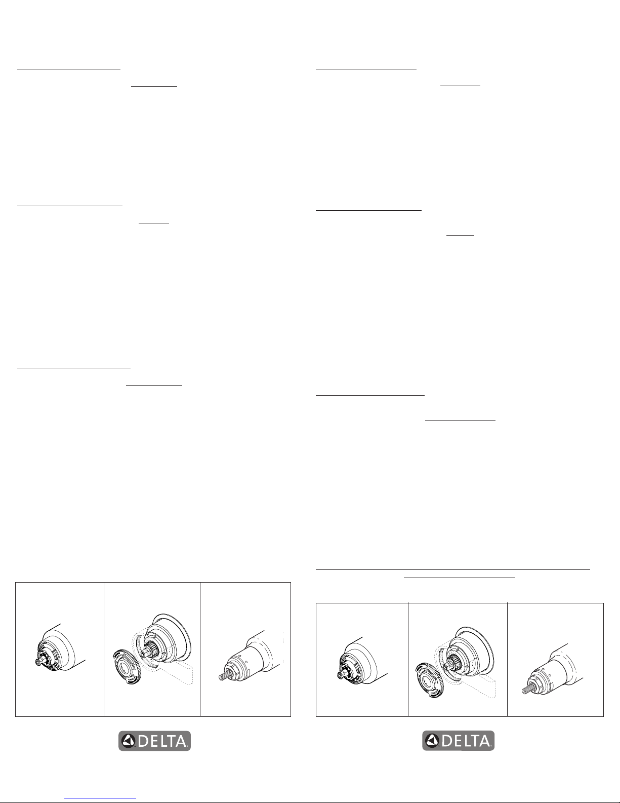
A.
B.
Turn off water supplies. Remove
cover (1), bonnet nut (2) and test cap (3)
from the body. If this is not a thin wall
mounting, the entire plasterguard (4)
may be removed. If screen (5) is in place,
remove before installing cartridge.
Insert adapter assembly (1) into valve
body. Make sure the adapter assembly
is correctly positioned and is pressed all
the way down inside body. Remove the
retainer (2) from the adapter.
Rotate cartridge (1) so the words
“HOT SIDE” (2) appear on the left. Insert
cartridge assembly into valve body.
Make sure the key (3) on the cartridge is
fully engaged with the slot in the brass
body (4). Slide bonnet nut (5) over the
cartridge and thread onto the body.
Hand tighten securely.
For back to back or reverse installations
(hot on right and cold on left): Rotate
cartridge (1) so the words “HOT SIDE” (2)
appear on the right. Install the cartridge
making sure that the key is fully engaged
with the slot in the brass body (See step C).
Slide bonnet nut (3) over the cartridge and
thread onto the body. Hand tighten securely.
3
C.
Back to back Installation
Normal Installation
(changes not required)
Reverse
Installation
Cold
Hot
1
2
3
5
4
1
2
1
3
4
5
2
1
3
2
Page 6
76652 Rev. G
58045
Installation
2
Showerhead and Tub Spout Installation
A.
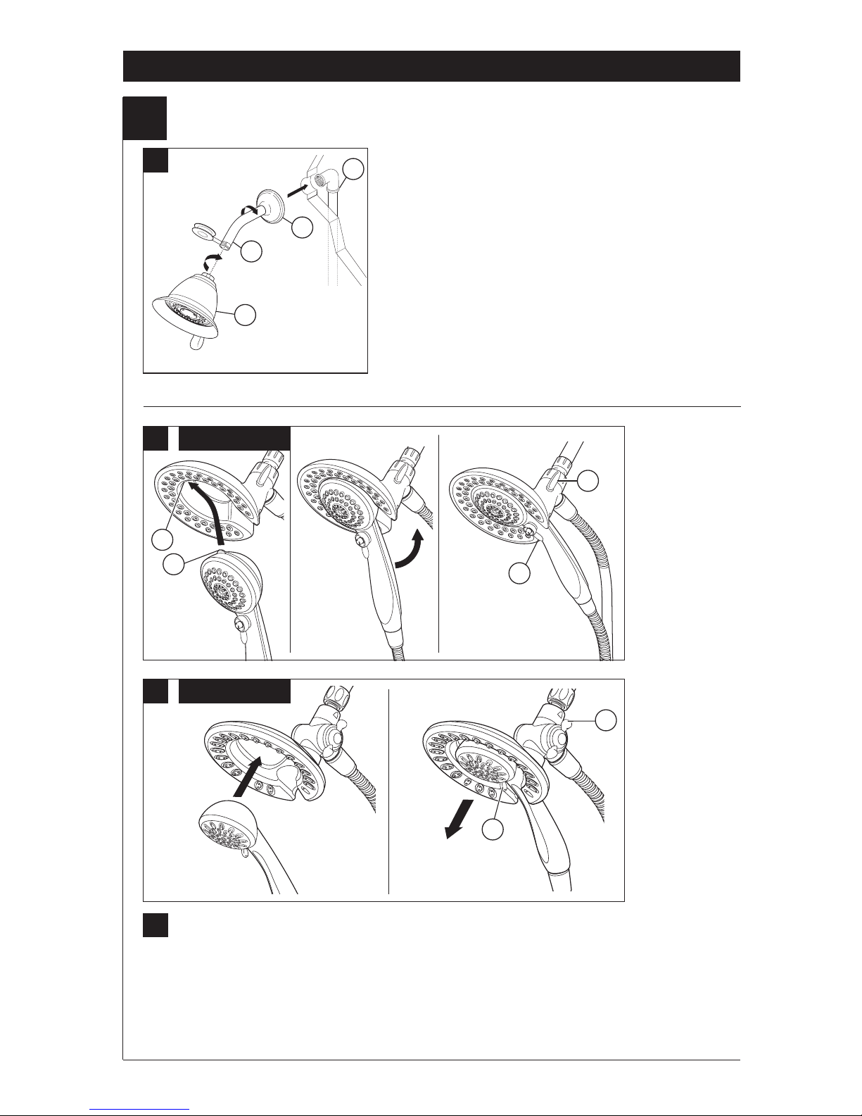
FOR SHOWERHEAD INSTALLATION: Connect top
outlet (1) to shower arm (2) with proper ttings. To
prevent damage to nish on shower arm, insert wall end
of shower arm into shower ange (3) before screwing
arm into riser connection. Thread showerhead (4) onto
shower arm. Apply plumber tape to pipe threads on both
ends. Do not overtighten showerhead.
B.
B.
58045: To combine the two showers, insert the top tab (1) on the handshower into the slot (2) of
the showerhead. Push the handshower into the showerhead until the two parts snap together.
58065: To combine the two showers, push the handshower into the showerhead, then pull down
on the handshower until locked with the showerhead.
If the showerhead moves when removing the handshower, hand tighten the connection between
the showerhead and the shower arm.
To change spray modes, turn the lever (3) left or right to the desired setting. Turn knob (4) to
change between showerhead only, showerhead and handshower or handshower only.
4
58045
B.
58065
1
2
3
4
1
2
3
4
3
4
Page 7
76652 Rev. G
Installation
2
5
Showerhead and Tub Spout Installation
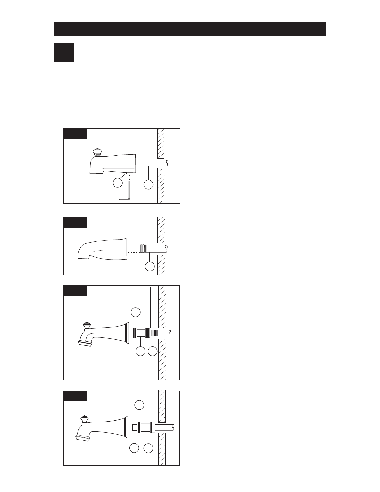
FOR TUB SPOUT INSTALLATION:
Refer to the installation instructions supplied with your spout. Do not connect deck mount spouts to
in-wall valves. Do not use hand showers connected in lieu of a tub spout to a tub/shower valve. Do not
use PEX tubing for tub spout drop.
Slip-On Installation
The copper tube (1) must be 1/2” nominal
copper. Important: If it is necessary to cut the
copper tube, the end must be chamfered free of
burrs to prevent cutting or nicking O-ring inside
the spout. Slide spout over copper tube ush
with the nished tub or wall surface. Tighten set
screw (2), but do not overtighten.
Iron Pipe Installation
Install threaded pipe nipple (1) to extend past
nished wall. Apply plumber tape to threads on
pipe nipple and screw on tub spout.
C-2
C-1
2
1
1
Copper Sweat Installation
Remove O-ring (1) from adapter (2). Solder
adapter to tube taking care to keep solder away
from O-ring groove. CAUTION: NO SOLDER
PERMITTED ON OUTSIDE DIAMETER OF
ADAPTER ADJACENT TO O-RING GROOVE.
Cut off tube (3) and replace O-ring on groove of
brass adapter. Thread tub/spout onto adapter,
taking care not to damage O-ring, and hand
tighten until spout is rmly against nished wall
and all slack is taken up behind wall.
Iron Pipe Installation
Installation of easy-on universal tub spout
Install pipe nipple so that end of nipple projects out
from nished wall surface 1/2" to 1 1/4" (13 mm to
32 mm).
Apply plumber tape or pipe dope to pipe threads.
Hand tighten adapter (1) onto pipe nipple (2). Finish
tightening with standard pipe wrench until a positive
seal is implemented. Take care not to damage
O-Ring (3) groove. Back of adapter (1) must not
project more than 1" (25 mm) from nished wall
surface.
Hand tighten tub spout onto adapter (1) taking care
not to damage the O-Ring (3).
C-4
C-3
1
2
3
1/2" to 1 1/4"
(13 mm to 32 mm)
1 2
3
Page 8

76652 Rev. G
Installation
3
6
Trim Installation
A.
B.
Escutcheon Installation for
Models T17053, T17253, T17453,
T17067, T17267 & T17467.
Slide O-ring (1) over cartridge and the
bonnet nut (2). The O-ring, which acts as
a spacer to steady the sleeve, should rest
behind the bonnet nut. Slide the sleeve
(3) over the cartridge, body and O-ring.
Ensure sleeve is properly positioned over
the front of cartridge.
Install volume control handle (1) with lever
to the right, then turn to the on position.
DO NOT SECURE WITH SCREW.
Secure the escutcheon (1) and backplate (2)
(if your model has one) to the bracket (3) using
the 2 screws provided (4). Do not overtighten
escutcheon screws.If you are installing the
Cassidy models T17097, T17297 & T17497:
Thread the cover (5) onto the escutcheon (1).
For models T17053, T17253, T17453, T17067,
T17267 & T17467:
Install bracket (5) over the cartridge body using
the 2 screws provided (6). Install escutcheon (7)
by placing it over the bracket as shown and
rotating it to lock the tabs (8). Secure the escut-
cheon to the bracket using set screw (9).
C.
8
9
7
6
5
8
4
1
2
3
5
1
2
3
1
Page 9

76652 Rev. G
Installation
4
Installation and Adjustment of the Rotational Limit Stop
A.
B.
Place the temperature control knob (1) on
volume handle and rotate to the mixed
position
(if required). DO NOT SECURE WITH
SCREW. Turn on water supplies; let the
water
run until both hot and cold water is as hot/
cold
as possible. Place thermometer in a plastic
tumbler, and hold the tumbler in the water
stream. Record the temperature reading.
Secure temperature control knob (1) with
screw (2). Hook (3) front of temperature
control cover (4) onto knob (1) before
engaging rear snap (5).
If the water temperature is above 120°F,
remove the temperature control knob (1)
and rotate the limit stop (2) clockwise one
tooth for every 4°F - 6°F (approximate)
change in temperature. If water temperature
is cooler than desired, rotate the limit stop
counterclockwise.
IMPORTANT: The rst position of the
Rotational Limit Stop (the Limiter) is that
position that restricts the rotation of the
stem the most and is at the maximum
clockwise setting. According to industry
standards, the maximum allowable
temperature of the water exiting from the
valve is 120
o
F. This temperature may vary
in your local area. The Rotational Limit Stop
may need to be readjusted if the inlet water
temperature changes. For instance, during
the winter, the cold water temperature is
colder than it is during the summer which
could result in varying outlet temperatures.
Typical temperature for a comfortable bath
or shower is between 90o–110o F.
7
5
Potential scald or thermal shock injury could result due to cross ow if outlet at the
shower is blocked or restricted (e.g., pause control on showerhead). Be sure to point
showerhead away from you when re-starting ow or install inlet check valves on both
supply lines to prevent possible injury.
C-1
C-2
Hotter
Colder
Secure temperature control knob (1) with
screw (2). snap on temperature control cover
(3) with side snaps onto knob (1).
3
1
5
2
4
1
2
3
1
2
1
Page 10

76652 Rev. G
Clean and Care
Care should be given to the cleaning
of this product. Although its nish is
extremely durable, it can be damaged by
harsh abrasives or polish. To clean, simply
wipe gently with a damp cloth and blot dry
with a soft towel.
Warning: Scrubbing Bubbles
®
Bathroom
Cleaner and Lysol
®
Basin Tub and Tile
Cleaner must not be used on the clear knob
handles and levers. Use of these cleaners
can result in cracked or severely damaged
handles. If overspray gets onto the handles,
immediately wipe them dry with a soft
cotton cloth.
Maintenance
Faucet leaks from tub spout/showerhead:
SHUT OFF WATER SUPPLIES.
Replace valve cartridge
RP46463 or RP32104
See Helpful Hints 1, 2, 3 & 4.
Helpful Hints:
1. Before removing valve cartridge assembly for any
maintenance, be sure to note the position of the
rotational limit stop on the cap. The valve cartridge
assembly must always be put back in the same
position. BE SAFE! After you have nished the
installation, turn on valve to make sure COLD
WATER FLOWS FIRST.
2. To remove valve cartridge from body, shut off
water supplies and remove handle and bonnet nut.
Do not pry the valve cartridge out of the body with
a screwdriver. Place handle on stem and rotate
counterclockwise approximately 1/4 turn after the
stop has been contacted. Lift valve cartridge out
of body.
Remove seats and springs and replace.
Place the largest diameter of the spring into the
seat pocket rst and then press the tapered end
of the seal over the spring. Reassemble valve
cartridge and replace in body following instructions
given in 1 above.
3. If the water in your area has lime, rust, sand
or other contaminants in it, your pressure
balance valve will require periodic inspection.
The frequency of the inspection will depend
on the amount of contaminants in the water. To
inspect valve cartridge remove it and follow the
steps in note 1 above. Turn the valve to the full
mix position and shake the cartridge vigorously.
If there is a rattling sound, the unit is functional
and can be reinstalled following instructions given
in note 1 above. If there is no rattle, replace the
housing assembly with the proper RP.
8
Cartridge Summary Reference Sheet
Units shipped in March
2006 and after.
Units shipped before
March 2006.
Order RP46463 to
Replace Cartridge.
Order RP32104 to
Replace Cartridge.
Grey Upper Cap
White Upper Cap
V Notch
Square Notch
Adapter
Shorter Tab Longer Tab
17 1700
Page 11

76652 Rev. G
Instrucciones para la
Instalación del Accesorio
para Válvulas MultiChoice
®
Manual para los
Propietarios
17 Series
Escriba aquí el número del modelo comprado.
Usted puede necesitar
Para las piezas de repuesto adicionales, visite www.deltafaucet.com
Contenido:
Garantías ................................................................................. Page 2
Instrucciones de Instalación .................................................... Pages 3 - 7
Limpieza y Cuidado de su Liave .............................................. Page 8
Mantenimiento .......................................................................... Page 8
Hoja resumen de referencia para el cartucho ...........................Page 8
Piezas de Repuesto de la Serie Clásica .................................. Pages 10
compañía y la fecha cuando ajustó el Tope del
Límite Rotacional y aplicar o jar la etiqueta al
dorso de la puerta del gabinete más cercano
y la etiqueta de aviso al calentador de agua.
Deje la Hoja de Instrucciones para referencia
del dueño/usuario.
ADVERTENCIA: Esta válvula de presión
balanceada y termostática está diseñada
para minimizar los efectos de los cambios
de temperatura de agua por causa de los
cambios de presión en el agua de entrada,
comúnmente causados por lavadoras de
platos, lavadoras de ropa, inodoros, y otros
aparatos por el estilo. Puede no proporcionar
protección de quemaduras de agua caliente
cuando hay alguna falla de otros aparatos
para el control de temperatura en otro
sitio en el sistema de plomería. También
no proporcionará protección si el tope del
límite rotacional la temperatura no está
apropiadamente jo o si cambia la
temperatura del agua caliente después de
hacer los ajustes o si los cambios del gua
de entrada son por los cambios estacionales.
ADVERTENCIA: No instale un aparato de corte
o cierre en cualquiera de las tomas de esta
válvula. Cuando este tipo de aparato cierra el
ujo de agua, puede hacer fallar la habilidad
de la válvula de balancear las presiones del
agua caliente y fría.
4/11/2017
1
ESTA VÁLVULA CUMPLE O EXCEDE LAS
SIGUIENTES NORMAS: ASME A112.18 1 / CSA
B125.1 y ASSE 1016 (Type -P- or -T-).
ADVERTENCIA: El instalador debe apostar
este systema/divisa para garantizar temperatura
maximo y seguro. Cualqueir cambio en el ajuste
puede subir la temperatura del agua de descarga
sobre el límite considerado seguro y puede
resultar en quemaduras de agua caliente.
AVISO PARA EL INSTALADOR: PRECAUCIÓN
– Como instalador de esta válvula, es su
responsabilidad de INSTALAR Y AJUSTAR
apropiadamente esta válvula como se describe
en las instrucciones, por lo tanto, debe haber
una persona para hacer los ajustes necesarios
del Tope del Límite Rotacional y del pomo
para la temperatura en el momento que se
haga la instalación y pueda necesitar ajustes
adicionales por los cambios estacionales
de la temperatura del agua. USTED DEBE
informarle al dueño/usuario sobre este
requisito siguiendo las instrucciones. Si usted
o el dueño/usuario no están seguros como
hacer estos ajustes apropiadamente, por favor
reérase al Página 7 y si todavía no está seguro,
llámenos al 1-800-345-DELTA.
Después de hacer la instalación y el ajuste, usted
puede agregarle a la etiqueta de aviso
proporcionada, su nombre, el nombre de
lacompañía y la fecha cuando ajustó el Tope del
T
E
F
L
O
N
Page 12

76652 Rev. G
Garantía Limitada De Por Vida de la Llave y su Acabado
Piezas y acabado
Todas las piezas (excepto las piezas electrónicas y las
pilas) y los acabados de esta llave de agua Delta®
están garantizados al consumidor comprador original de
estar libres de defectos en material y fabricación
durante el tiempo que el comprador original posea la
vivienda en la que la llave de agua fue originalmente
instalada o, para los consumidores comerciales, durante
5 años a partir de la fecha de compra.
Componentes electrónicos y pilas (si aplicable)
Todas las piezas (salvo las pilas), si hay, de esta llave
de agua Delta® están garantizadas al consumidor
comprador original de estar libres de defectos en
materiales y fabricación durante 5 años a partir de la
fecha de compra o, para los usuarios comerciales, por
un año a partir de la fecha de compra. No se garantizan
las pilas.
Delta Faucet Company reemplazará, SIN CARGO,
durante el período de garantía aplicable, cualquier pieza
o acabado que pruebe tener defectos de material y/o
fabricación bajo la instalación, uso y servicio normal. Si
la reparación o su reemplazo no es práctico, Delta
Faucet Company tiene la opción de reembolsarle su
dinero por la cantidad del precio de compra a cambio de
la devolución del producto. Estos son sus únicos
recursos.
Delta Faucet Company recomienda que use los
servicios de un plomero profesional para todas las
instalaciones y reparaciones. También le recomendamos
que utilice sólo las piezas de repuesto
originales de Delta®.
Delta Faucet Company no será responsable por
cualquier daño a la llave de agua que resulte del
mal uso, abuso, negligencia o mala instalación o
mantenimiento o reparación incorrecta, incluyendo
el no seguir los cuidados aplicables y las instrucciones
de limpieza.
Las piezas de repuesto se pueden obtener llamando al
número correspondiente más abajo, o
escribiendo a:
En los Estados Unidos y México:
Delta Faucet Company
Product Service
55 E. 111th Street
Indianapolis, IN 46280
1 800 345 DELTA (3358)
customerservice@deltafaucet.com
En Canadá:
Masco Canada Limited, Plumbing Group
Technical Service Centre
350 South Edgeware Road
St. Thomas, Ontario, Canada N5P 4L1
1 800 345 DELTA (3358)
customerservice@mascocanada.com
La prueba de compra (recibo original) del comprador
original debe ser disponible a Delta Faucet Company para
todos los reclamos a menos que el comprador haya
registrado el producto con Delta Faucet Company. Esta
garantía le aplica sólo a las llaves de agua de Delta®
fabricadas después del 1 de enero 1995 e instaladas en los
Estados Unidos de América, Canadá y México.
DELTA FAUCET COMPANY NO SE HACE RESPONSABLE
POR CUALQUIER DAÑO ESPECIAL, INCIDENTAL
O CONSECUENTE (INCLUYENDO LOS GASTOS DE
MANO DE OBRA) POR EL INCUMPLIMIENTO DE
CUALQUIER GARANTÍA EXPRESA O IMPLÍCITA DE LA
LLAVE DE AGUA. Algunos estados/provincias no permiten la
exclusión o limitación de daños especiales, incidentales o
consecuentes, por lo que estas limitaciones y exclusiones
pueden no aplicarle a usted. Esta garantía le otorga
derechos legales. Usted también puede tener otros
derechos que varían de estado/provincia a estado/provincia.
Esta es la garantía exclusiva por escrito de Delta Faucet
Company y la garantía no es transferible.
Si usted tiene alguna pregunta o inquietud acerca de
nuestra garantía, por favor, vea nuestra sección de
preguntas frecuentes FAQ sobre la garantía en
www.deltafaucet.com, también puede enviarnos un correo
electrónico a customerservice@deltafaucet.com o llámenos
al número que le corresponda anteriormente incluido.
Garantia Limitada de Delta HDF
Todas las piezas de la llave Delta HDF están
garantizadas al dueño original de estar libres de
defectos en materiales y en la mano de obra por un
período de cinco (5) años. Esta garantía se hace al
dueño original y será efectiva el día de la compra como
se ve en el recibo de compra.
Delta reemplazará, LIBRE DE CARGO, durante el
período de la garantía, cualquier pieza que resulte
defectuosa en materiales y/o en la mano de obra bajo
instalación, uso y servicio normal. Las piezas de
repuesto pueden ser obtenidas de su comerciante o
distribuidor local que se encuentran en la guía telefónica
o si usted devuelve la pieza con el recibo de compra
a nuestra fabrica, Y LOS CARGOS DE TRANSPORTE
PAGADOS CON ANTELACION, a la dirección dada.
ESTA GARANTIA ES LA UNICA GARANTIA EXPRESA
DE DELTA. CUALQUIER RECLAMO HECHO BAJO
ESTA GARANTIA TIENE QUE SER HECHO DURANTE
EL PERIODO DE CINCO AÑOS A QUE SE REFIERE
ARRIBA. CUALQUIER GARANTIA IMPLICITA,
INCLUYENDO LA GARANTIA IMPLICITA DE
COMERCIALIZACION O CONVENIENCIA PARA UN
PROPOSITO PARTICULAR, SON LIMITADOS EN
DURACION A LA DURACION DE ESTA GARANTIA.
LOS CARGOS PARA LA MANO DE OBRA Y/O DAÑOS
INCURRIDOS EN LA INSTALACION, REPARACION O
REEMPLAZO, ASI COMO LOS DAÑOS INCIDENTALES
O CONSECUENTES CONECTADOS CON
ELLOS SON EXCLUIDOS Y NO SERAN PAGADOS
POR DELTA.
Algunos estados no permiten limitaciones al tiempo que
dura la garantía implícita, o la exclusión o limitación de
los daños incidentales o consecuentes, así que la
limitación o exclusión expresada arriba puede no ser
aplicable a usted.
Esta garantía le da a usted derechos legales especícos
y usted puede también tener otros derechos que varían
de estado a estado.
Esta garantía es nula por cualquier daño a esta llave
que sea el resultado del mal uso, abuso, negligencia,
accidente, instalación impropia, cualquier uso en
violación de las instrucciones suministradas por
nosotros o cualquier uso de piezas de repuesto que no
sean piezas genuinas Delta.
www.deltafaucet.com
© 2017 Masco Corporación de Indiana
2
Page 13

76652 Rev. G
Instalación
1
Instalación del Cartucho
Cierre los suministros de agua. Quite la
cubierta (1), la tuerca tapa (2) y la tapa de
prueba (3). Si no es para instalar en pared
delgada, puede quitar el protector (4) de yeso
completo. Si la pantalla (5) está en lugar, quite
antes de instalar el cartucho.
Introduzca el adaptador (1) en la válvula.
Asegúrese que el adaptador estén
correctamente colocados dentro de los
oricios en la base de la válvula. Quite el
retenedor (2) del adaptador.
Gire el cartucho (1) de manera que las
palabras ‘HOT SIDE’ (LADO CALIENTE) (2)
aparezcan en la izquierda. Introduzca el
cartucho en la válvula. Asegúrese que la
guía (3) en el cartucho esté totalmente
encajada en la muesca del cuerpo de
latón (4). Deslice la tuerca tapa (5) sobre
el cartucho y enrosque en el cuerpo de la
válvula. Apriete a mano bien.
3
En las instalaciones dorso con dorso (el agua
caliente en la derecha y la fría en la izquierda):
Gire el cartucho (1) de manera que las palabras
“HOT SIDE” (LADO CALIENTE) (2) aparezcan
en la derecha. Instale el cartucho asegurando
que la guía quede totalmente encajada en la
muesca de la pieza de latón. Deslice la tuerca
tapa (3) sobre el cartucho y enrosque en el
cuerpo de la válvula. Apriete a mano bien.
Instalación de Espalda a Espalda
Instalación Normal
(No serequerá cambios)
Instalación
Invertido
Fría
Caliente
C.
A.
B.
1
2
3
5
4
1
2
1
2
3
4
5
1
2
3
Page 14

76652 Rev. G
Instalación
2
Instalación de la Cabeza de la Regadera y el Surtidor de la Bañera
PARA LAS INSTALACIONES DE LAS CABEZAS
DE REGADERA: Conecte la toma de salida de
agua superior (1) al brazo de la regadera (2) con los
accesorios apropiados. Para prevenir daño al acabado
del brazo de la regadera, introduzca el extremo que
va hacia la pared del brazo de la regadera dentro del
reborde (3) antes de atornillar el brazo en la conexión de
la tubería vertical. Aplique cinta para plomero a los enrosques
de la tubería. No apriete demasiado la cabeza de la
regadera.
B.
58045: Para combinar las dos regaderas, inserte la lengüeta superior (1) en la regadera de mano
en la muesca (2) de la cabeza de la regadera. Oprima la regadera de mano en la cabeza de la
regadera hasta que las dos partes encajen y queden juntas.
58065: Para combinar las dos regaderas, oprima la regadera de mano en la cabeza de la regadera
hasta que las dos partes encajen y queden juntas. A continuación, tire hacia abajo la regadera de
mano hasta que quede ja con la cabeza de la regadera.
Si la cabeza de la regadera se mueve cuando retira la regadera manual, apriete a mano la
conexión entre la cabeza de la regadera y el brazo de la regadera.
Para cambiar los modos de rocío de la regadera, mueva la palanca (3) de izquierda a derecha al
ajuste deseado. Gire la perilla (4) (para cambiar el ujo de agua para que salga sólo por la cabeza
de la regadera, o por la cabeza de la regadera y regadera manual o sólo por la regadera manual.
4
58045
A.
B.
58045
B.
58065
1
2
3
4
1
2
3
4
3
4
Page 15

76652 Rev. G
Instalación
2
5
Instalación de la Cabeza de la Regadera y el Surtidor de la Bañera
PARA LA INSTALACIóN DEL SURTIDOR DE LA BAÑERA: Reérase a las instrucciones para la
instalación suministradas con su surtidor. No conecte los surtidores para las instalaciones en las
supercies horizontales en las válvulas dentro de las paredes. No use las regaderas de mano en vez
de un surtidor de bañera conectado a una válvula de bañera/regadera. No use la tubería PEX como
tubería entre la válvula y el surtidor de la bañera.
Instalación deslizable
El tubo de cobre (1) debe ser de1/2” de cobre
nominal. Importante: Si es necesario cortar el
tubo de cobre, el extremo debe biselarse que
quede libre de rebabas para prevenir cortar o
mellar el aro O dentro del tubo de cobre. Deslice
el surtidor sobre el tubo de cobre al ras con la
bañera o la supercie de la pared acabada.
Apriete el tornillo de ajuste (2), pero no apriete
demasiado.
Instalación de la tubería de Hierro
IInstale una entrerrosca de tubo enroscado de
1/2” (13 mm) (1) para extenderse por delante
de la pared acabada. Aplique cinta para plomero
a las roscas en la entrerrosca de tubo y atornille el
surtidor de la bañera.
C-2
C-1
2
1
1
Instalación del tubo de hierro
Instalación del tubo de salida de agua del easyon universal para bañeras
Instale la entrerrosca del tubo de manera que el
extremo de ésta sobresalga de la pared acabada
1/2" a 1 1/4" (13 mm a 32 mm).
Aplique cinta para plomero o compuesto para tubos
a las roscas del tubo. Apriete a mano el adaptador
(1) a la entrerrosca del tubo (2). Termine apretando
con una llave de tubos estándar hasta que el sello
positivo se implemente. Tenga cuidado de no dañar
la muesca del anillo-O (3). La parte posterior del
adaptador (1) no debe sobresalirse más de 1" (25
mm) de la supercie de la pared acabada.
Apriete a mano el tubo de salida de agua de la
bañera al adaptador (1) teniendo cuidado de no
dañar el anillo - O (3).
C-3
1 2
3
1/2" a 1 1/4"
(13 mm a 32 mm)
Instalación de Soldadura de Cobre
Quite el aro O (1) del adaptador (2). Suelde el
adaptador al tubo asegurando de mantener la
soldadura lejos de las muesca del aro O. AVISO:
NO SE PERMITE SOLDAR EN EL DIAMETRO
EXTERIOR DEL ADAPTADOR ADJUNTO A
LA MUESCA DEL ARO O. Corte el tubo (3)
y coloque otra vez el aro O en la muesca del
adaptador de latón. Atornille la bañera/surtidor
al adaptador, asegurando no dañar el aro O, y
apriete a mano bien hasta que el surtidor quede
rmemente contra la pared acabada y no quede
ojo detrás de la pared.
C-4
1
2
3
Page 16

76652 Rev. G
Instalación
3
Instalación Final
La instalación de la roseta para los
modelos T17053, T17253, T17453,
T17067, T17267 y T17467.
Deslice el aro O (1) sobre el cartucho y la
tuerca tapa (2). El aro O, el cual funciona
como un separador para estabilizar la
manga, debe quedar apoyado en la
tuerca tapa. Deslice la manga (3) sobre el
cartucho, el cuerpo de la pieza y el aro O.
Instale la manija de control del volumen
(1) con la palanca hacia la derecha, luego
gírela a la posición abierta. NO FIJE CON
TORNILLO.
Fije la roseta con oricio (1) y la placa de atrás
(2) (si su modelo tiene una) al soporte (3)
usando los 2 tornillos suministrados (4). No
apriete demasiado los tornillos de la roseta.
Si está instalando the Cassidy Modelos
T17097, T17297 y T17497:
Gira la tapa(5) en la cubierta de oricio(1).
Para los modelos T17053, T17253, T17453,
T17067, T17267 y T17467:
Instale el soporte (5) sobre el cuerpo del
cartucho usando los 2 tornillos incluidos (6).
Instale la chapa de base (7) colocándola sobre
el soporte como se muestra y girándola para
que encaje enlas muescas (8). Fije la chapa
de base alsoporte usando el tornillo de ajuste (9).
6
A.
C.
1
2
3
1
B.
8
9
7
6
5
8
4
1
2
3
5
Page 17

76652 Rev. G
4
Instalación y Ajuste del Tope que Limita la Rotación
B.
Instalación y Ajuste del Tope que Limita la
Rotación Coloque la perilla para el control de
la temperatura (1) en la manija para controlar
el volumen y gire a la posición mixta (si se
requiere). NO FIJE CON TORNILLO. Abra los
suministros de agua; deje que el agua corra
hasta que ambas, el agua caliente y la fría,
estén lo más caliente/fría posible. Coloque el
termómetro en un vaso plástico, y sostenga el
vaso debajo del chorro de agua. Tome nota de
la temperatura.
Fije la perilla para el control de la temperatura
(1) con un tornillo (2) .Gancho (3) delantero
coloque la perilla para el control de couverture
(4) encima de perilla (1) antes de la participación
parte trasera instantánea (5).
Si la temperatura del agua es más de 120°F,
quite la perilla para el control de la temperatura
(1) y gire el tope (2) en sentido de las
manecillas del reloj un diente por cada
4°F-6°F (aproximadamente) de cambio de
temperatura. Si la temperatura del agua es
más fría de lo deseado, gire el tope en
sentido contrario de las manecillas del reloj.
IMPORTANTE: La primera posición del tope
que limita la rotación (el pare) es aquella que
limita más la rotación de la espiga y es la
que está en la colocación máxima en sentido
contrario a las manecillas del reloj.
De acuerdo a los estándares de la industria, la
temperatura máxima permitida del agua qu e
sale de la válvula es 120° F. Esta temperatura
puede variar en su área. Si el agua de entrada
cambia de temperatura, se puede requerir el
reajuste del tope que limita la rotación. Por
ejemplo, durante el invierno, la temperatura
del agua fría es más fría que durante el
verano, esto puede resultar en temperaturas
variadas de agua de entrada. La temperatura
típica para un baño o ducha agradable es
entre 90°–110° F.
7
5
Si la ducha está bloqueado o restringido, puede resultar posiblemente quemadura o
lesion por ejemplo, cesa a contral la ducha Asegúrese salir ducha cuando encender otra
vez el ujo o instalar válvulas para evitar lesion posible.
C-2
Más Fría
Más Caliente
Instalación
Fije la perilla para el control de la
temperatura
(1) con un tornillo (2) coloque la perilla para
el
control de cubierta (3) encima de perilla(1).
A.
C-1
1
1
2
3
2
1
1
5
2
4
3
Page 18

76652 Rev. G
Limpieza y Cuidado de su Llave
Tenga cuidado al ir a limpiar este producto.
Aunque su acabado es sumamente durable,
puede ser afectado por agentes de limpieza
o para pulir abrasivos. Para limpiar su llave,
simplemente frótela con un trapo húmedo y
luego séquela con una toalla suave.
¡ADVERTENCIA! No se puede usar
SCRUBBING BUBBLES® BATHROOM
CLEANER o LYSOL® BASIN TUB AND TILE
CLEANER en las manijas transparentes. El uso
de estos productos pueden resultar en manijas
rajados o severamente dañados. Si estos
productos caen sobre la manija, séquelo
inmediatamente con una toalla de algodón suave.
Mantenimiento
La llave tiene fugas de agua en la
salida de tina/cabeza deregadera–
CIERRE LOS SUMINISTROS DE AGUA.
Reemplace cartucho de la válvula
RP46463 o RP32104
Vea Sugerencia Utiles 1, 2, 3, y 4.
Sugerencia Utiles:
1. Antes de remover el ensamble del cartucho de
la válvula para hacerle cualquier servicio, fíjese en
la posición del tope del límite rotacional ubicado en
la tapa. Siempre se debe reponer el ensamble de
cartucho de válvula en el mismo posición. TENGA
CUIDADO después de cumplir el instalación dele
vuelta a la válvula para asegurar que AGUA FRIA
SALGA PRIMERO.
2. Para quitar el cartucho de válvula del cuerpo,
cierre los suministros de agua y quite el maneral y
bonete. No se debe quitar el cartucho de válvula
del cuerpo con atornillador. Ponga el maneral
encima el vástago y giralo en el sentido contrario
al de las agujas del reloj aproximado 1/4 vuelta.
Levanta el cartucho de válvula aguera el cuerpo.
Separa ensambles de botón y caja. Quite los
asientos y resortes y ponga los asientos y
resortes nuevos. Ponga primero el diámetro mas
grande del resorte adentro la bolsa del asiento
y luego apreta el remate ahus ado del sello hacia
arriba el resorte. Reensembla el cartucho de
válvula y repongalo en el cuerpo siguendo los
instrucciones en nota 1 arriba.
3. Si la agua en su area contiene cal, orín, arena
o otros contaminamientos, su válvula de equilibrio
de presión requerá inspecciones periódico. La
frequencía de los inspecciones depende en el
tamaño de contaminamientos en la agua. Para
inspectar el cartucho, quite el cartucho, sigue los
pasos apuntado en nota 1 arriba. Dele vuelta al
válvula hasta el posición completamente mixto
y sacude el cartucho riguroso. Si hay traqueteo,
funciona el unidad y se puede reinstalar siguendo
nota 1 de arriba. Si no hay traqueteo, reemplace
el ensamble de caja.
8
Hoja resumen de referencia para el cartucho
Unidades enviadas en
Marcha de 2006 y después.
Unidades enviadas antes de
Marcha de 2006.
Ordene el Repuesto RP46463
para cambiar el cartucho.
Ordene el Repuesto RP32104
para cambiar el cartucho.
Tapa Gris Superior
Tapa Blanca Superior
Muesca V
Muesca
Cuadrada
Adaptador
Más corto Tapa Lengüeta más Larga
17 1700
Page 19

76652 Rev. G
Instructions d’installation
Finition de la soupape
MultiChoice
®
Guide d’utilisation
17 Séries
Inscrivez le numéro de modèle ici.
Articles dont vous pouvez avoir besoin:
Pour les pièces de rechange supplémentaires, visitez www.deltafaucet.com
Table des matières
Garanties .................................................................................. Page 2
Instructions d’installation .......................................................... Pages 3 - 7
Instructions de nettoyage .......................................................... Page 8
Maintenance .............................................................................. Page 8
Fiche de référence sommaire de la cartouche .......................... Page 8
Pièces de Rechange de Séries Classiques ............................... Page 10
fournie, votre nom, le nom de votre entreprise et la
date à laquelle vous avez réglé la butée limitatrice
de température, puis xer l’étiquette à l’endos de
la porte de la coiffeuse. Vous devez également
xer l’étiquette d’avertissement au chauffe-eau.
Veuillez laisser ce feuillet d’instructions au
propriétaire ou à l’utilisateur pour qu’il puisse
le consulter au besoin.
MISE EN GARDE – Ce robinet thermostatique
à équilibrage de pression pour baignoire est
conçu pour limiter les effets des uctuations de
température de l’eau causées par les variations
de la pression d’alimentation attribuables au
fonctionnement d’un lave-vaisselle, d’une
machine à laver, d’un cabinet d’aisances ou
d’un autre appareil qui consomme de l’eau.
Il peut ne pas protéger l’utilisateur contre
l’échaudage en cas de défectuosité d’un autre
dispositif de régulation de la température,
si le réglage de la butée limitatrice de haute
température est mauvais, si la température de
l’eau chaude a été modiée après que les
réglages ont été effectués ou si la température
de l’eau d’alimentation a changé en raison du
changement de saison.
MISE EN GARDE – N’installez pas de dispositif
d’arrêt sur une sortie quelconque de ce robinet.
En interrompant l’écoulement de l’eau, ce
dispositif peut empêcher le robinet d’équilibrer
les pressions d’eau chaude et d’eau froide.
4/11/2017
1
Ce robinet satisfait aux exigences des normes
ASME A112.18.1/CSA B125.1 et ASSE 1016
(Type -P- or -T-) ou les surpasse.
ATTENTION: L’installateur doit régler l’appareil
pour que la température maximale de l’eau chaude
soit sans danger. Toute modication des réglage
peut entraîner une élévation de la température à
la sorite du robinet au delà de la température sans
danger et pourrait causer un échaudage.
AVIS À L’INSTALLATEUR : ATTENTION! – En
qualité d’installateur, vous êtes tenu
d’INSTALLER et de RÉGLER ce robinet
conformément aux instructions. Ce robinet ne
s’adapte pas automatiquement aux uctuations
de la température de l’eau d’alimentation. Par
conséquent, il faut régler la butée limitatrice de
température au moment de l’installation et il
peut être nécessaire de faire de nouveaux
réglages par la suite en raison des uctuations
saisonnières de la température de l’eau.
VOUS DEVEZ informer le propriétaire ou
l’utilisateur de cette exigence. En cas de doute
quant à la marche à suivre pour faire ces
réglages, veuillez consulter page 7 si un
doute persiste, et si cette ince rtitude
persiste, appelez-nous au 1-800-345-DELTA.
Après avoir terminé l’installation et le réglage, vous
devez inscrire, sur l’étiquette de mise en garde
fournie, votre nom, le nom de votre entreprise et la
T
E
F
L
O
N
Page 20

76652 Rev. G
Garantie à vie limitée des robinets et de leurs nis
Pièces et nis
Toutes les pièces (à l’exception des composants
électroniques et des piles) et tous les nis de ce robinet
Delta® sont protégés contre les défectuosités du matériau
et les vices de fabrication par une garantie qui est
consentie au premier acheteur et qui demeure valide tant
que celui-ci demeure propriétaire de la maison dans
laquelle le robinet a été installé. Dans le cas d’une
utilisation commerciale, la garantie est de 5 ans à compter
de la date d’achat.
Composants électroniques et piles (le cas échéant)
Si ce robinet Delta® comporte des composants
électroniques, ces composants (à l’exception des piles)
sont protégés contre les défectuosités du matériau et les
vices de fabrication par une garantie consentie au premier
acheteur qui est d’une durée de 5 ans à compter de la
date d’achat. Dans le cas d’une utilisation commerciale, la
garantie est d’un an à compter de la date d’achat. Aucune
garantie ne couvre les piles.
Delta Faucet Company remplacera, GRATUITEMENT,
pendant la période de garantie applicable, toute pièce ou
tout ni qui présentera une défectuosité du matériau et/ou
un vice de fabrication pour autant que le robinet ait été
installé, utilisé et entretenu normalement. S’il est
impossible de réparer ou de remplacer le robinet, Delta
Faucet Company pourra décider de rembourser le prix
d’achat du produit pour autant que celui-ci lui soit retourné.
Il s’agit de vos seuls recours.
Delta Faucet Company recommande de coner
l’installation et la réparation à un plombier professionnel.
Nous vous recommandons également d’utiliser
uniquement des pièces de rechange authentiques Delta®.
Delta Faucet Company se dégage de toute responsabilité
à l’égard des dommages causés au robinet en raison d’un
mauvais usage, d’un usage abusi f, de la négligence ou de
l’utilisation d’une méthode d’installation, de maintenance
ou de réparation incorrecte ou inadéquate, y compris
les dommages résultant du non-respect des instructions
de nettoyage et d’entretien applicables. Garantie limitée
des robinets Delta® Pour obtenir des pièces de rechange,
veuillez appeler au numéro applicable ci-dessous ou écrire
à l’adresse applicable ci-dessous.
Aux États-Unis et au Mexique :
Delta Faucet Company
Product Service
55 E. 111th Street
Indianapolis, IN 46280 St.
1-800-345-DELTA (3358)
customerservice@deltafaucet.com
Au Canada:
Masco Canada Limited, Plumbing Guoup
Thechnical Service Centre
350 South Edgware Roard
Thomas, Ontario, Canada N5P 4L1
1-800-345-DELTA (3358)
customerservice@mascocanada.com
La preuve d’achat (reçu original) du premier acheteur doit
être présentée à Delta Faucet Company pour toutes les
demandes en vertu de la garantie, sauf si le produit a été
enregistré auprès de Delta Faucet Company. La présente
garantie s’applique uniquement aux robinets Delta®
fabriqués après le 1er janvier 1995 et installés aux
États-Unis d’Amérique, au Canada et au Mexique.
DELTA FAUCET COMPANY SE DÉGAGE DE TOUTE
RESPONSABILITÉ À L’ÉGARD DES DOMMAGES
PARTICULIERS, CONSÉCUTIFS OU INDIRECTS (Y
COMPRIS LES FRAIS DE MAIN-D’OEUVRE) QUI
POURRAIENT RÉSULTER DE LA VIOLATION D’UNE
GARANTIE IMPLICITE OU EXPLICITE QUELCONQUE
SUR LE ROBINET. Dans les États ou les provinces
où il est interdit de limiter ou d’exclure la responsabilité à
l’égard des dommages particuliers, consécutifs ou
indirects, les limites et les exclusions susmentionnées ne
s’appliquent pas.
La présente garantie vous donne des droits précis qui
peuvent varier selon l’État ou la province où vous résidez.
La présente garantie écrite est la garantie exclusive offerte
par Delta Faucet Company et elle n’est pas transférable.
Si vous avez des questions ou des préoccupations en ce
qui concerne notre garantie, veuillez consulter la page
Warranty FAQs à www.deltafaucet.com, faire parvenir un
courriel à customerservice@deltafaucet.com ou nous
appeler au numéro applicable.
Garantie Limitée sur les Robinets Ultra-Robustes Delta de la Série HDF
Toutes les pièces des robinets ultra-robustes Delta de la
série HDF sont protégées contre les défectuosités du
matériau et les vices de conception par une garantie qui
est consentie au premier acheteur pour une période de
cinq (5) ans. Cette garantie entre en vigueur à compter de
la date d’achat indiquée sur le reçu de l’acheteur.
Pendant la période de garantie, Delta remplacera, SANS
FRAIS, toute pièce présentant une défectuosité du
matériau et (ou) un vice de fabrication pour autant que
l’appareil ait été installé, utilisé et entretenu correctement.
Pour obtenir des pièces de rechange, veuillez
communiquer avec le distributeur ou le concessionnaire de
votre région dont le nom gure dans l’annuaire
téléphonique ou retourner la pièce défectueuse
accompagnée du reçu de l’acheteur à notre usine, PORT
PAYÉ, à l’adresse indiquée. LA PRÉSENTE GARANTIE
EST LA SEULE GARANTIE IMPLICITE OFFERTE PAR
DELTA. TOUTE RÉCLAMATION EN VERTU DE CETTE
GARANTIE DOIT ÊTRE FAITE AU COURS DE LA
PÉRIODE DE CINQ ANS SUSMENTIONNÉE. TOUTE
GARANTIE IMPLICITE, Y COMPRIS LA GARANTIE
IMPLICITE DE QUALITÉ MARCHANDE OU
D’ADÉQUATION DU PRODUIT AVEC UN USAGE
PARTICULIER, EST LIMITÉE À LA DURÉE DE LA
PRÉSENTE GARANTIE. LES FRAIS DE
MAIN-D’OEUVRE ET (OU) LES DOMMAGES
PROVOQUÉS AU COURS DE L’INSTALLATION, DE LA
RÉPARATION OU DU REMPLACEMENT D’UN
ÉLÉMENT AINSI QUE LES PERTES OU LES
DOMMAGES INDIRECTS EN RÉSULTANT NE SONT
PAS COUVERTS PAR CETTE GARANTIE.
Là où il est interdit de limiter la durée de la garantie
implicite ou les responsabilités à l’égard des dommages
indirects, les exclusions et les limites susmentionnées ne
s’appliquent pas.
La présente garantie vous donne des droits précis qui
peuvent varier selon votre lieu de résidence.
Les dommages résultant d’une mauvaise utilisation, d’une
utilisation abusive, de la négligence, d’un accident, d’une
mauvaise installation, du non respect de nos instructions
ou de l’utilisation de pièces de rechange autres que des
pièces d’origine Delta ne sont pas couverts par la garantie.
www.deltafaucet.com
© 2017 Division de Masco Indiana
2
Page 21

76652 Rev. G
C.
B.
Installation dos à dos
Installation normale
(Non modiée)
Installation
Inversée
Eau Froides
Eau Chaude
Installation
1
Installation de la cartouche.
A.
Interrompez l’arrivée d’eau. Enlevez le
couvercle (1), l’écrou à portée sphérique (2)
et le capuchon d’essai (3) du corps.
Si vous n’installez pas l’appareil dans une
paroi mince, vous pouvez retirer le protecteur
(4) complètement. Si l’écran (5) est en place,
enlevez avant d’installer la cartouche.
Introduisez l’adaptateur (1) dans le corps
de la soupape. Assurez-vous que les joints
toriques sont positionnés correctement dans
les trous à la base du corps. Retirez la pièce
de retenue (2) de l’adaptateur.
Tournez la cartouche (1) de sorte que la
mention « HOT SIDE » (2) se trouve du côté
gauche. Introduisez la cartouche dans le corps
de la soupape. Assurez-vous que l’ergot (3)
sur la cartouche est parfaitement engagé dans
la rainure du corps en laiton (4). Faites glisser
l’écrou à portée sphérique (5) sur la cartouche
et vissez-le sur le corps. Serrez à la main
fermement.
Dans le cas d’une installation dos à dos ou
inversée (eau chaude à droite et eau froide à
gauche) : Tournez la cartouche (1) de sorte que
la mention « HOT SIDE »(2) se trouve du côté
droit. Installez la cartouche en vous assurant
que l’ergot est parfaitement engagé dans la
rainure du corps en laiton. Faites glisser l’écrou à
portée sphérique (3) sur la cartouche et vissez-le
sur le corps. Serrez à la main fermement.
3
1
2
3
5
4
2
1
1
1
2
3
3
2
4
5
Page 22

76652 Rev. G
Installation
2
Installation de la pomme de douche et du bec de baignoire
INSTALLATION DE LA POMME DE DOUCHE :
Raccordez la sortie supérieure (1) au tuyau
d’alimentation de la pomme de douche (2) à l’aide des
raccords appropriés. Pour éviter d’abîmer le ni du
tuyau de la pomme de douche, introduisez le côté «
mur » de celui-ci dans la collerette (3) avant de le visser
dans le raccord du tuyau vertical. Appliquez du ruban
de plomberie sur les lets. Vissez la pomme de douche
(4) sur le tuyau. Appliquez du ruban de plomberie sur les
lets. Prenez garde de serrer la pomme de douche
excessivement.
B.
58045: Pour combiner les deux douches, introduisez la patte supérieure (1) de la douche à
main dans la rainure (2) de la pomme de douche. Poussez la douche à main dans la pomme de
douche jusqu’à ce que les deux éléments se bloquent ensemble et deviennent solidaires.
58065: Pour combiner les deux douches, poussez la douche à main dans la pomme de douche,
tirez ensuite sur la douche à main pour la verrouiller avec la pomme de douche.
Si la pomme de douche bouge pendant que vous retirez la douche à main, serrez le raccord
entre la pomme de douche et le bras de douche à la main.
Pour changer le mode de pulvérisation, tournez la manette (3) vers la gauche ou la droite selon
le réglage désiré. Utilisez le bouton (4) pour sélectionner les modes douche seulement, douche
et douche à main ou douche à main seulement.
4
58045
A.
B.
58045
B.
58065
1
2
3
4
1
2
3
4
3
4
Page 23

76652 Rev. G
Installation
2
5
Installation de la pomme de douche et du bec de baignoire
INSTALLATION DU BEC DE BAIGNOIRE :
Consultez les instructions d’installation fournies avec le bec. Ne raccordez pas à une soupape murale à un
bec conçu pour être monté sur une plage. Ne raccordez pas une douche à main à la sortie d’un robinet de
baignoire-douche prévue pour un bec de baignoire. N’utilisez pas de tube PEX pour raccorder le bec.
Installation d’un bec coulissant
Le tube de cuivre (1) doit avoir un diamètre
nominal de1/2 po. Important : Si vous devez
couper le tube de cuivre, chanfreinez son
extrémité de sorte qu’elle ne risque pas
d’endommager le joint torique à l’intérieur du
bec. Faites glisser le bec sur le tube de cuivre de
sorte qu’il s’appuie contre la surface nie de la
baignoire ou du mur. Serrez la vis de calage (2),
mais prenez garde de la serrer excessivement.
Installation à l’aide d’un tuyau de fer
Installez le manchon leté (1) 1/2 po (13 mm) de
manière que sa saillie par rapport à la surface
nie du mur. Appliquez du ruban de plomberie sur
les lets du manchon et xez celui-ci au bec de
baignoire en vissant.
C-2
C-1
2
1
1
Installation à l’aide d’un tuyau de cuivre brasé
Retirez le joint torique (1) de l’adaptateur (2).
Brasez l’adaptateur au tube en prenant garde
d’échapper du métal d’apport dans la rainure pour le
joint torique. ATTENTION : IL NE DOIT PAS Y AVOIR
DE MÉTAL D’APPORT SUR LA CIRCONFÉRENCE
EXTÉRIEURE DE L’ADAPTATEUR PRÈS DE LA
RAINURE POUR LE JOINT TORIQUE. Coupez le
tube (3) et remettez le joint torique en place dans la
raInure de l’adaptateur en laiton. Vissez le bec de
baignoire sur l’adaptateur et prenant garde d’abîmer
le joint torique. Serrez le bec à la main jusqu’à ce
qu’il s’appuie solidement contre la surface nie de la
paroi et qu’il n’y ait plus de jeu derrière le mur.
C-4
1
2
3
Installation sur un tuyau de fer
Installation du bec de baignoire polyvalent easy-on
Installez le manchon leté de manière qu’il présente
une saillie de 1/2 à 1 1/4 po (13 mm à 32 mm) par
rapport à la surface nie du mur.
Appliquez du ruban de plomberie ou du composé à
letage sur les lets. Montez l’adaptateur (1) sur le
manchon (2) et serrez-le à la main. Finissez ensuite
le serrage à l’aide d’une clé à tube pour rendre le joint
étanche. Prenez garde d’abîmer le rainure du joint
torique (3). Les dos de l’adaptateur (1) ne doit pas se
trouver à plus de 1 pouce (25 mm) par rapport à la
surface nie du mur.
Montez le bec de baignoire sur l’adaptateur (1) et
serrez-le à la main en prenant soin de ne pas abîmer
le joint torique (3).
C-3
1 2
3
1/2 po a 1 1/4 po
(13 mm to 32 mm)
Page 24

76652 Rev. G
Installation
3
6
Installation des pièces de nition
A.
Faites glisser le joint torique (1) sur la
cartouche et l’écrou à portée sphérique
(2). Le joint sert de pièce d’espacement
et il stabilise le manchon; il doit se trouver
derrière l’écrou à portée sphérique. Faites
glisser le manchon (3) sur la cartouche, le
corps et le joint torique.
Installez la manette de réglage de débit
(1) de manière qu’elle pointe vers la droite,
puis placez-la en position d’ouverture. NE
LA FIXEZ PAS AVEC LA VIS.
Fixez la rosace (1) et la plaque arrière (2) (si le
modèle que vous installez encomporte une) sur
le support (3) à l’aide des 2 vis fournies (4).
Prenez garde de serrerles vis de la rosace
excessivement. Si vous installez Cassidy
Modèles T17097, T17297 et T17497:
Enlez le couvercle (5) sur l'écusson (1).
Pour les modèles T17053, T17253, T17453
T17067, T17267 et T17467:
Montez la xation (5) sur le corps de la cartouche
à l’aide des 2 vis fournies (6). Installez la plaque
de nition (7) en la plaçant sur la xation comme
le montre la gure et tournez-la pour bloquer les
pattes (8). Fixez la plaque de nition à la xation
à l’aide de la vis de calage (9).
C.
Installation de la rosace pour les
modèles
T17053, T17253, T17453,
T17067, T17267 et T17467.
B.
8
9
7
6
5
8
4
1
1
2
3
2
3
5
1
Page 25

76652 Rev. G
Installation
4
Installation et réglage de la butée anti-échaudage
B.
Placez le bouton de réglage de température
(1) sur la manette de réglage de débit et
tournez-le jusqu’à la position de mélange
(au besoin). NE LE FIXEZ PAS AVEC LA
VIS. Rétablissez l’alimentation en eau.
Laissez couler l’eau jusqu’à ce que l’eau
froide soit aussi froide que possible et
que l’eau chaude soit aussi chaude que
possible. Mettez un thermomètre dans un
gobelet en plastique, puis placez le gobelet
sous le jet d’eau et attendez un peu. Notez
la température de l’eau.
Fixez le bouton de réglage de température (1)
avec la vis (2) et, accrocher avant ou poussant
fermement sur calez le couvercle (3) sur bouton
avant de engageant arrière bouton (1).
Si la température de l’eau sur le
thermomètre est supérieure à 120 °F,
retirez le bouton de réglage de température
(1) et tournez la butée anti-échaudage (2)
dans le sens horaire d’un cran par tranche
de température d’environ 4 à 6 °F. Si l’eau
n’est plus assez chaude, tournez la butée
a nti-échaudage dans le sens antihoraire.
IMPORTANT: La première position de la
butée anti-échaudage est celle qui limite
le plus la rotation de la tige; elle se trouve
à l’extrémité de la plage dans le sens
horaire. Selon les normes de l’industrie, la
température maximale de l’eau à la sortie
de la soupape ne doit pas dépasser 120 ° F.
La température peut varier selon la région.
Le réglage de la butée anti-échaudage
peut être modié si la température de
l’eau d’alimentation a changé. À titre
d’exemple, la température de l’eau froide
est plus basse en hiver, ce qui inuence
la température de l’eau à la sortie de la
soupape. La température idéale de l’eau
pour un bain ou une douche se situe entre
90 et 110 ° F.
7
5
La brûlure potentielle ou la blessure de choc thermique pourraient résulter du ux si
la sortie à la douche est bloquée ou restreint (par exemple, le contrôle de pause sur
douche). Assurez-vous de diriger la douche loin de vous en reprenant le ux ou installer
des valves de contrôle d'admission sur les deux conduites d'alimentation pour empêcher
la blessure possible.
C-2
Plus Chaud
Plus Froid
Fixez le bouton de réglage de température
(1) avec la vis (2) et, en poussant fermement
sur celuici, calez le couvercle (3) sur le bouton (1).
A.
C-1
1
2
3
1
1
2
1
5
2
3
4
Page 26

76652 Rev. G
Instructions de nettoyage
Il faut le nettoyer avec soin. Même si son
ni est extrêmement durable, il peut être
abîmé par des produits fortement abrasifs
ou des produits de polissage. Il faut
simplement le frotter doucement avec un
chiffon humide et le sécher à l'aide d'un
chiffon doux.
de Baignoires et de Carreaux Lysol
®
sur
les manettes et les poignées sphériques
transparentes. Ces produits peuvent faire
ssurer les poignées et les manettes ou
les abîmer gravement. Si ces poigneés
ou ces manettes sont aspergées
accidentellement par l’un ou l’autre
des produits mentionnés, les essuyer
immédiatement à l’aide d’un chiffon de
coton doux.
Maintenance
Le robinet fuit par le bec ou la pomme de
douche. COUPER L’EAU.
Remplacer la cartouche RP46463 ou RP32104
Voir les conseils 1, 2, 3, et 4.
Conseils:
1. Avant d’enlever la cartouche de la soupape aux
ns d’entretien, prenez note de la position de la
butée de température maximale sur le chapeau.
La cartouche doit toujours être reposée dans la
même position. NE PAS PRENDRE DE RISQUES
INUTILEMENT. Une fois l’installation terminée,
ouvrir le robinet pour s’assurer que L’EAU FROIDE
S’ÉCOULE EN PREMIER.
2. Pour déposer la cartouche du corps, couper l’eau,
puis retirer la poignée et le chapeau leté. Ne pas
utiliser un tournevis comme levier pour extraire la
cartouche. Placer la poignée sur la tige et la tourner
dans le sens antihoraire d’environ 1/4 de tour après
contact des butées. Soulever la cartouche pour la
retirer du corps.
Enlever les sièges et les ressorts, puis les
reposer. Placer d’abord l’extrémité du ressort du
plus grand diamètre dans le logement du siège,
puis abaisser l’extrémité conique du siège sur le
ressort. Remonter la cartouche et la reposer dans
le corps conformément aux instruction gurant en
“1” ci-dessus.
3. Si l’eau d’alimentation du robinet à équilibrage
de pression renferme du calcaire, du fer, du sable
ou d’autres corps étrangers, celui-ci doit faire
l’objet d’inspections périodiques. La fréquence
des inspections dépend de la quantité de corps
étrangers dans l’eau. Pour inspecter la cartouche,
la déposer et suivre et les instructions de la note 1
ci-dessus. Ouvrir la soupape en position de plein
mélange et secouer la cartouche vigoureusement.
Si des cliquetis se font entendre, le composant est
en bon état et peut être reposé conformément aux
instructions de la note 1 ci-dessus. Si on n’entend
pas de cliquetis, remplacer le boîtier.
8
AVERTISSEMENT: N’employez pas le
nettoyant pour salle de bain Scrubbing
Bubbles
®
ni le Nettoyant de Lavabos,
Fiche de référence sommaire de la cartouche
Unités expédiées en
Mars 2006 et après.
Unités expédiées avant
Mars 2006.
Commandez le kit RP46463
pour remplacer la cartouche.
Commandez le kit RP32104
pour remplacer la cartouche.
Capuchon supérieur gris
Capuchon supérieur blanc
Encoche
en V
Encoche carrée
Adaptateur
Attache plus
courte
Attache plus
longue
17 1700
Page 27

76652 Rev. G
9
For illustrative purposes, the replacement parts for the 17
Series Classic Collection are shown on the following page.
For replacement parts on all other collections, please refer to
the parts diagrams available on www.deltafaucet.com.
Para los nes ilustrativos, las piezas de repuesto para la
Colección Clásica de la Serie 17 se muestran en la siguiente
página. Para las piezas de repuesto sobre todas las demás
colecciones, por favor reérase a los diagramas de piezas
disponibles en www.deltafaucet.com.
A des ns d’illustrations, les pièces de rechange de la
Collection Série Classique 17 sont montrées sur la page
suivante. Pour les pièces de rechange de toutes les autres
collections, veuillez vous référer aux diagrammes des
pièces sur www.deltafaucet.com.
Page 28

76652 Rev. G
T17030, T17130, T17230, T17230-H2O, T17430 & T17430-H2O
Models / Modelos / Modèles
RP6025
▲
Shower Flange
Pestaña de
la Rogadora
Collerette
RP6023
▲
Shower Arm
Brazo de la Rogadora
Tuyau de Pomme de Douche
Refer to page 8 for more information. / Consulte con la página 8 para más información. /
Pour obtenir de plus amples renseignements, reportez-vous à la page 8.
*
10
RP70173
▲
Showerhead
Cabeza de Rogadora
Pomme de Douche
RP43381
▲
Showerhead
Cabeza de Rogadora
Pomme de Douche
▲
Specify Finish
Especifíque el Acabado
Précisez le Fini
RP28795
▲
Escutcheon
Roseta
Rosace avec Orice
RP196
▲
Trim Screws/Atornillos de
Franja/Vis de Finition
RP12630
▲
For Longer Screws
Para Tornillos Más Grandes
Pour Vis Plus Longues
RP46463
Cartridge Assembly
Cartucho
Cartouche
*
RP23336
O-Ring
Anillo "O"
Joint Torique
RP50880▲†
Trim Sleeve
Manga de Fran ja
Manchon de Finition
† Designates the accent
color on split nish models.
† Designa el color para
acentuar los modelos
con acabados divididos.
† Désigne la couleur
contrastante sur les
modèles à deux nis
RP32105
Screw/Tornillo/Vis
NOTE: Do NOT
overtighten screw.
NOTA: NO apriete
demasiado el
tornillo.
NOTE: NE serrez
PAS trop la vis.
RP73642
▲
Temperature Knob and Cover
Perilla de la Temperatura y Cubierta
Poigneé de Réglage de Température
RP32102
Rotational Limit Stop
Tope para Limitar
Butée Rotative
RP73643
▲
Handle Assembly
Ensamble de la Manija
Poignée
RP5833
▲
(Metal/Metálico/Métal)
Tub Spout/Non Diverter
Tubo de Salida para Bañera/
Sin Desviador
Bec/Sans Dérivation
RP17453
RP17454
▲
Tub Spout/Pull-Down Diverter
Tubo de Salida para Bañera/
Desviador de Halar
Bec/Avec Dérivation sur Embout
RP77992
(ordered separately/venden por
separado/vendues séparément)
Available Extension Kit
Juego de extensión
Kit de rallonge
RP46073
Adapter Assembly
Adaptador
Adaptateur
Page 29

76652 Rev. G
Notes / Notas / Notes
Page 30

76652 Rev. G
Delta Faucet Company
Product Service
55 E. 111th Street
Indianapolis, IN 46280
 Loading...