

Delta MultiChoice 72264, MultiChoice 13 Series, MultiChoice 14 Series Installation Instructions Manual
Page 1

IMPORTANT DOCUMENTS ENCLOSED
CAUTION:
To reduce the risk of injury due to hot water
burns, make sure the enclosed labels are
applied where specified on the label.
DOCUMENTOS IMPORTANTES INCLUIDOS
AVISO:
Para reducir el riesgo de lesión por
quemaduras de agua caliente, asegúrese que
las etiquetas incluidas se han aplicado donde
se ha especificado en la etiqueta.
DOCUMENTS IMPORTANTS À L’INTÉRIEUR
MISE EN GARDE :
Pour réduire le risque d’ébouillantage, veuillez
apposer les étiquettes fournies aux endroits
indiqués sur celles-ci.
72264
72264
Page 2
12/20/12 72264 Rev B
NOTICE TO INSTALLER: Place this label on the water heater next
to the temperature adjustment knob.
WARNING:
These series of tub/shower valves do not adjust automatically
for changes in temperature at the hot water heater or inlet. If the
temperature setting of the hot water heater or inlet is changed, the setting
on these valves must be adjusted manually! Failure to re-adjust the valve
may result in hot water burns or extreme cold resulting from variations
in line pressure (such as when a dishwasher or washing machine is
in use while you are taking a shower). After installation, verify that the
rotational limit stop on the valve is set so that changes in line pressure or
temperature do not result in uncomfortable water temperature changes.
If the temperature setting of the hot water heater or inlet is changed
after installation of the valve, the setting of the rotational limit stop
or temperature knob also must be changed! Consult the installation
instruction sheet for instructions on how to make this setting, or call us at
1-800-345-DELTA.
AVISO AL INSTALADOR: Coloque esta etiqueta en el calentador
de agua al lado de la perilla para el ajuste de temperatura.
AVISO:
Esta serie de válvulas para bañeras/regaderas no se ajustan automáticamente a los cambios de temperatura en el calentador de agua o en
el agua de entrada. Si el ajuste de la temperatura del calentador de agua
o la temperatura del agua que entra cambia ¡El ajuste de estas válvulas
se debe hacer manualmente! El no reajustar la válvula puede resultar en
quemaduras por agua caliente o temperaturas de agua extremadamente
frías resultando en variaciones de presión y temperatura (como cuando el
fregador de platos o la lavadora están funcionando mientras que se baña).
Después de la instalación, verifique que el control o tope del límite rotacional
en la válvula está ajustada para que los cambios de presión y de temperatura en la línea no resulten en cambios incómodos de temperatura del agua.
Si el ajuste de la temperatura del calentador de agua o de la entrada de
agua se cambia después de la instalación de la válvula, el ajuste del
tope del límite rotacional o la perilla de ajuste ¡también se debe cambiar! Consulte con su hoja de instrucciones de instalación para saber como
se ajusta o cambia el ajuste, o llámenos al 1-800-345-DELTA.
AVIS À L’INSTALLATEUR: Fixez cette étiquette sur le chauffe-eau
près du bouton de réglage de température.
ATTENTION :
La soupape de robinet de baignoire ou de douche de cette série
ne se règle pas automatiquement en fonction des changements de
température de l’eau chaude au chauffe-eau ou de l’eau d’alimentation.
En cas de modification du réglage de température du chauffe-eau ou de la
température de l’eau d’alimentation, le réglage de cette soupape doit être
modifié manuellement! Si le réglage de la soupape n’est pas modifié, le
robinet pourra permettre l’écoulement d’eau très chaude susceptible de causer
l’ébouillantage ou d’eau très froide, sous l’effet des variations de pression et de
température dans la tuyauterie d’alimentation (lorsque la douche est utilisée
en même temps que le lave-vaisselle ou la machine à laver, par exemple).
Après l’installation, assurez-vous que la butée de température maximale
sur la soupape est réglé de manière que les fluctuations de pression et de
température dans la tuyauterie d’alimentation n’entraînent pas de changements
de température de l’eau inconfortables. En cas de modification du réglage de
température du chauffe-eau ou de la température de l’eau d’alimentation
après l’installation de la soupape, le réglage de la butée de température
maximale ou du bouton de température doit être modifié! Pour régler
le bouton de température, consultez la feuille d’instructions d’installation ou
appelez-nous au 1-800-345-DELTA.
12/20/12 72264 Rev B
BY/POR/PAR _______________ COMPANY/COMPANIA/COMPAGNIE ________________
DATE/FECHA/LE ___________ PHONE/TELÉFONO/TELÉPHONE ____________________
NOTICE TO INSTALLER: Place this label close to the valve where the owner
will see it, such as inside the door of a cabinet or vanity.
WARNING:
Water temperature changes due to seasonal or other inlet variations, such as changing the setting
on the hot water heater may require adjustment of the rotational limit stop on your tub/shower valve
to ensure a safe maximum temperature. These valve series do not automatically adjust for inlet
temperature changes. If changes occur and you are not sure how to make the necessary rotational
limit stop or temperature knob adjustments, please consult the installation instruction sheet
provided with this valve or call 1-800-345-DELTA. These valve series are designed to minimize the
effects of outlet water temperature changes due to inlet pressure changes, commonly caused by
dishwashers, washing machines, toilets and the like. They may not provide protection from hot
water burns when there is a failure of other temperature controlling devices elsewhere in
the plumbing system. After making the necessary adjustments please fill in the information below.
This valve/system has been set by the person listed below to ensure a safe maximum temperature.
Any change in the setting may raise the discharge temperature above the limit considered safe
and could lead to hot water burns. If this label has not been completed, you should verify that
the rotational limit stop or temperature knob has been properly adjusted to suit your individual
installation. The installation instruction sheet supplied with the valve provides information on how to
make this setting.
AVISO AL INSTALADOR: Coloque esta etiqueta cerca de la válvula donde el
propietario la pueda ver, tal como dentro de la puerta del gabinete o el tocador.
AVISO:
Los cambios de temperatura del agua por variaciones estacionales u otras variaciones en el
agua de entrada, como el cambio por el ajuste en el calentador de agua, puede requerir el
ajuste del tope del límite rotacional de la válvula de su unidad bañera/regadera para asegurar
una temperatura máxima segura. Esta serie de válvulas no se ajusta automáticamente para los
cambios de temperatura del agua de entrada. Si cambios ocurren y usted no está seguro como
hacer los ajustes necesarios con la perilla para controlar la temperatura, por favor consulte la hoja
de instrucciones de instalación proporcionada con esta válvula o llámenos al 1-800-345-DELTA.
Las válvulas de esta serie están diseñadas para minimizar los efectos por cambios de temperatura
en el agua de entrada por cambios en la presión del agua, comúnmente causados por el uso
simultáneo de fregadoras de platos, lavadoras, inodoros y aparatos similares. Estas pueden
no proporcionar protección de quemaduras por el agua caliente cuando hay una falla de
otros mecanismos que controlan la temperatura del agua en otro sitio del sistema de
plomería. Después de hacer los ajustes necesarios, por favor escriba la información suministrada
a continuación. Esta válvula/sistema ha sido ajustada por la persona indicada a continuación para
ayudar a asegurar una temperatura máxima segura. Cualquier cambio al ajuste puede aumentar
la temperatura del agua de descarga sobre el límite considerado seguro y puede resultar en
quemaduras por agua caliente. Si esta etiqueta no se ha llenado, debe verificar si el control o tope
del límite rotacional o la perilla que controla la temperatura han sido correctamente ajustadas al
gusto de su instalación individual. La hoja de instrucciones de instalación proporcionada con las
válvulas le suministra información sobre como hacer este ajuste.
AVIS À L’INSTALLATEUR: Fixez cette étiquette près du robinet, à la vue du
propriétaire, à l’intérieur de la porte du meuble ou de la coiffeuse, par exemple.
ATTENTION :
Les modifications de la température de l’eau attribuables au changement de saison ou à d’autres
facteurs, comme la modification du réglage du chauffe-eau, peuvent nécessiter un réglage de la
butée de température maximale de la soupape de votre robinet pour baignoire et de douche. La
soupape de robinet de ces séries ne se règle pas automatiquement en fonction des changements
de température de l’eau chaude de l’eau d’alimentation. En cas de modification de la température
de l’eau d’alimentation, si vous ne savez pas comment régler la butée de température maximale
ou le bouton de température, veuillez consulter le feuillet d’instructions d’installation fourni avec
la soupape ou appeler au 1-800-345-DELTA. La soupape de cette série est conçue pour limiter la
variation de la température de l’eau pouvant résulter des fluctuations de température et de pression
dans la tuyauterie d’alimentation. Ces fluctuations sont habituellement causées par une utilisation
simultanée du lave-vaisselle, de la machine à laver, d’un cabinet d’aisances ou d’un autre appareil
qui consomme de l’eau. La soupape peut ne pas protéger l’utilisateur contre l’ébouillantage
en cas de défectuosité d’un autre dispositif de régulation de la température de l’eau situé
ailleurs dans la tuyauterie. Après avoir effectué les réglages nécessaires, veuillez inscrire
l’information requise ci-dessous. Cet appareil de robinetterie a été réglé par la personne dont le
nom figure ci-dessous pour que la température maximale de l’eau soit sans danger. Toute modification du réglage peut occasionner une élévation de la température de l’eau à la sortie du robinet et
l’eau qui s’écoulera pourra être suffisamment chaude pour causer l’ébouillantage. Si la présente
étiquette n’a pas été remplie, assurez-vous que la butée de température maximale ou le bouton
de température a bien été réglé en fonction des caractéristiques de votre installation. La marche à
suivre pour faire le réglage figure dans les instructions d’installation fournies avec la soupape.
TO BE FILLED OUT BY THE INSTALLER / PARA SER LLENADO POR EL INSTALADOR /
A REMPLIR PAR L’INSTALLATEUR:
Rotational Limit Stop is located behind the disc.
13 / 14 Series
Hotter
Más
Caliente
Plus
Chaud
1st Position
Primera Posición
1ère Position
13 / 14 Series
Hotter
Más
Caliente
Plus
Chaud
1st Position
Primera Posición
1ère Position
Rotational Limit Stop is located behind the disc.
Page 3
MultiChoice® Valve Trim
Installation Instructions
Owners Manual
13/14
Series
Write purchased model number here.
ASME A112.18.1 / CSA B125.1
ASSE 1016
Table of Contents:
Warranty ............................................................................. Page 2
MultiChoice® Rough-In Installation Instructions ...................Pages 3 - 5
13/14 Series Installation Instructions .................................. Pages 6 - 9
Maintenance ....................................................................... Page 10
Cartridge Summary References ......................................... Page 10
To order replacement parts, visit www.deltafaucet.com
1
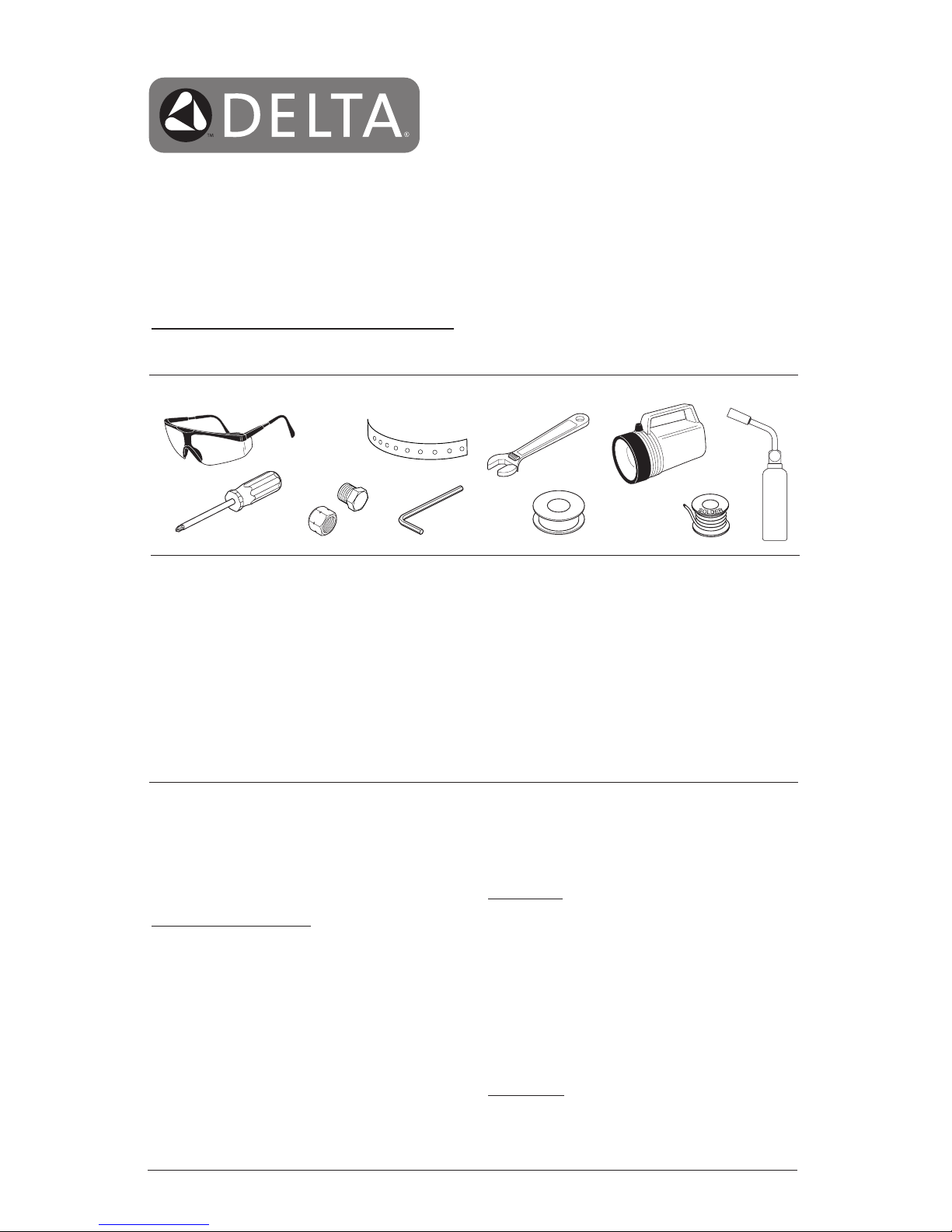
You May Need
T
E
F
L
O
N
12/20/12
72264 Rev. B
THIS VALVE MEETS OR EXCEEDS THE
FOLLOWING STANDARDS:
ASME A112.18.1/CSA B125.1 and ASSE 1016.
CAUTION: This system/device must be set by the
installer to ensure safe, maximum temperature.
Any change in the setting may raise the discharge
temperature above the limit considered safe and
may lead to hot water burns.
NOTICE TO INSTALLER: CAUTION!–As the
installer of this valve, it is your responsibility
to properly INSTALL and ADJUST this valve
per the instructions given. This valve does
not automatically adjust for inlet temperature
changes, therefore, someone must make the
necessary Rotational Limit Stop or temperature
knob adjustments at the time of installation and
further adjustments may be necessary due to
seasonal water temperature change. YOU MUST
inform the owner/user of this requirement by
following the instructions. If you or the
owner/user are unsure how to properly make
these adjustments, please refer to page 8, and if
still uncertain, call us at 1-800-345-DELTA.
After installation and adjustment, you must affix
your name, company name and the date you
adjusted the Rotational Limit Stop or temperature
knob to the caution label provided and apply or
attach the label to the back side of the closest
cabinet door and the warning label to the water
heater. Leave this Instruction Sheet for the
owner’s/user’s reference.
WARNING: This pressure balanced or
thermostatic bath valve is designed
to minimize the effects of outlet water
temperature changes due to inlet pressure
changes, commonly caused by dishwashers,
washing machines, toilets and the like. It may
not provide protection from hot water burns
when there is a failure of other temperature
controlling devices elsewhere in the
plumbing system, if the rotational limit stop
or temperature knob is not properly set or if
the hot water temperature is changed after the
settings are made or if the water inlet changes
due to seasonal changes.
WARNING: Do not install a shut-off device on
either outlet of this valve. When this type of
device shuts off the water flow, it can defeat
the ability of the valve to balance the hot and
cold water pressures.
Page 4
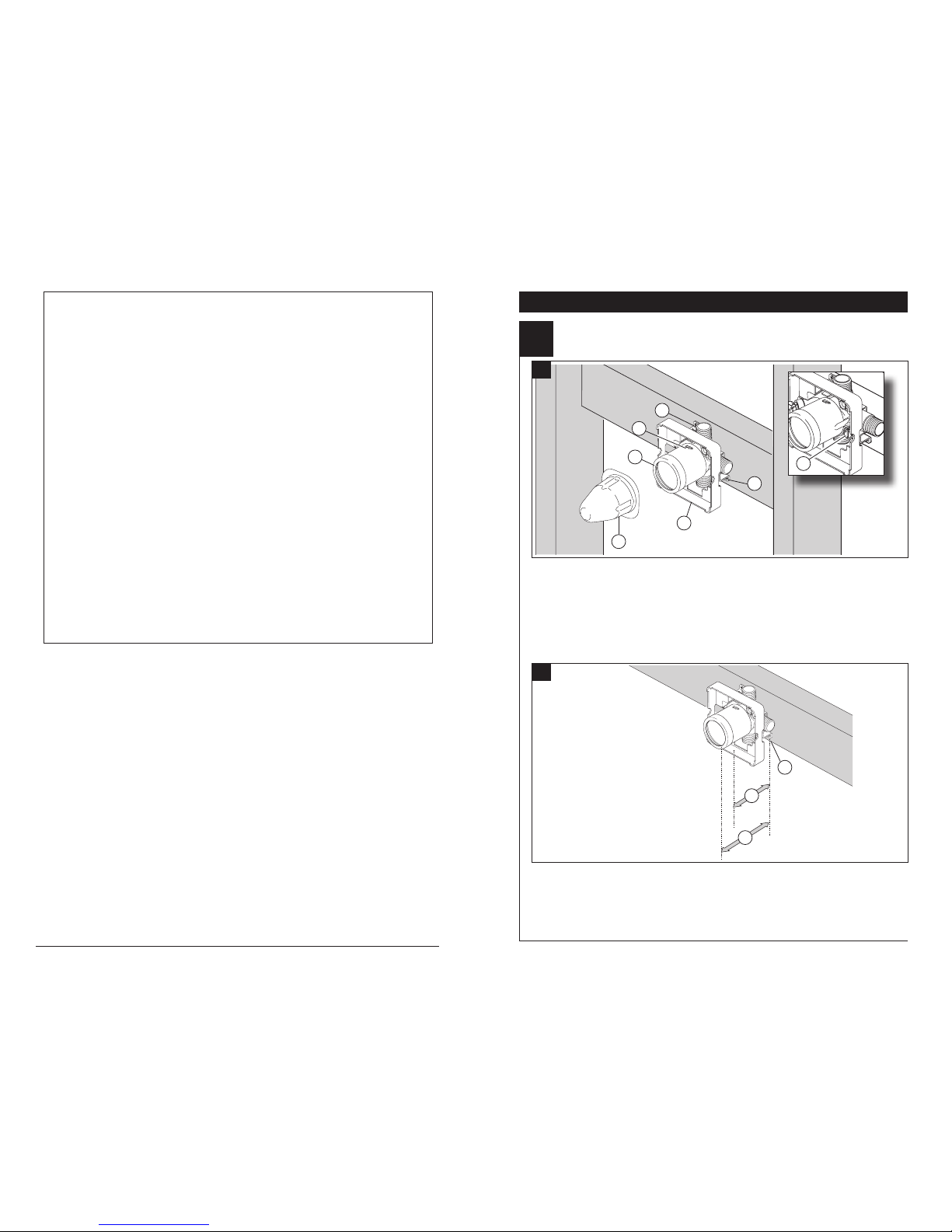
SHUT OFF WATER SUPPLIES.
Consider the type and thickness of your
finished wall before placing your stringer
back plate. Install the body (1) so the
surface of the finished wall is flush with the
front of the plasterguard (2) ± 3/8". Note:
For models with stops (3), plasterguard
MultiChoice® Rough-In Installation
1
A.
B.
Distance (1) from the stringer (2) to the
front of the plasterguard is 2.8" (71 mm).
Distance (3) from the stringer (2) to the
front of the bonnet is 3.9" (99 mm).
2
must be flush or subflush 3/8" to
finished wall. Mount body using the two
stringer mounting holes (4) on the bracket.
Note: Remove cover (5) to access
mounting holes. Make sure the word
“UP” (6) is on top of the valve body when
installing.
If a thin wall is used, be sure to have the
plasterguard behind the wall, otherwise
the wall should always be flush with the
front of the plasterguard. See instruction
on the bag for thin wall mounting.
1
2
6
5
4
4
1
3
2
3
3
© 2012 Masco Corporation of Indiana
Parts and Finish
All parts (other than electronic parts and batteries) and finishes of this Delta® faucet are warranted to the original
consumer purchaser to be free from defects in material and workmanship for as long as the original consumer
purchaser owns the home in which the faucet was first installed or, for commercial users, for 5 years from the
date of purchase.
Electronic Parts and Batteries (if applicable)
Electronic parts (other than batteries), if any, of this Delta® faucet are warranted to the original consumer
purchaser to be free from defects in material and workmanship for 5 years from the date of purchase or, for
commercial users, for one year from the date of purchase. No warranty is provided on batteries.
Delta Faucet Company will replace, FREE OF CHARGE, during the applicable warranty period, any part or
finish that proves defective in material and/or workmanship under normal installation, use and service. If repair
or replacement is not practical, Delta Faucet Company may elect to refund the purchase price in exchange for
the return of the product. These are your exclusive remedies.
Delta Faucet Company recommends using a professional plumber for all installation and repair. We also
recommend that you use only genuine Delta® replacement parts.
Delta Faucet Company shall not be liable for any damage to the faucet resulting from misuse, abuse, neglect
or improper or incorrectly performed installation, maintenance or repair, including failure to follow the applicable
care and cleaning instructions.
Replacement parts may be obtained by calling the applicable number below or by writing to:
In the United States and Mexico: In Canada:
Delta Faucet Company Masco Canada Limited, Plumbing Group
Product Service Technical Service Centre
55 E. 111th Street 350 South Edgeware Road
Indianapolis, IN 46280 St. Thomas, Ontario, Canada N5P 4L1
1-800-345-DELTA (3358) 1-800-345-DELTA (3358)
customerservice@deltafaucet.com customerservice@mascocanada.com
Proof of purchase (original sales receipt) from the original purchaser must be made available to Delta Faucet
Company for all warranty claims unless the purchaser has registered the product with Delta Faucet Company.
This warranty applies only to Delta® faucets manufactured after January 1, 1995 and installed in the United
States of America, Canada and Mexico.
DELTA FAUCET COMPANY SHALL NOT BE LIABLE FOR ANY SPECIAL, INCIDENTAL OR CONSEQUENTIAL
DAMAGES (INCLUDING LABOR CHARGES) FOR BREACH OF ANY EXPRESS OR IMPLIED WARRANTY
ON THE FAUCET. Some states/provinces do not allow the exclusion or limitation of special, incidental or
consequential damages, so these limitations and exclusions may not apply to you. This warranty gives you
special legal rights. You may also have other rights which vary from state/province to state/province.
This is Delta Faucet Company’s exclusive written warranty and the warranty is not transferable.
If you have any questions or concerns regarding our warranty, please view our Warranty FAQs at www.
deltafaucet.com, email us at customerservice@deltafaucet.com or call us at the applicable number above.
Limited Warranty on Delta® Faucets
Page 5
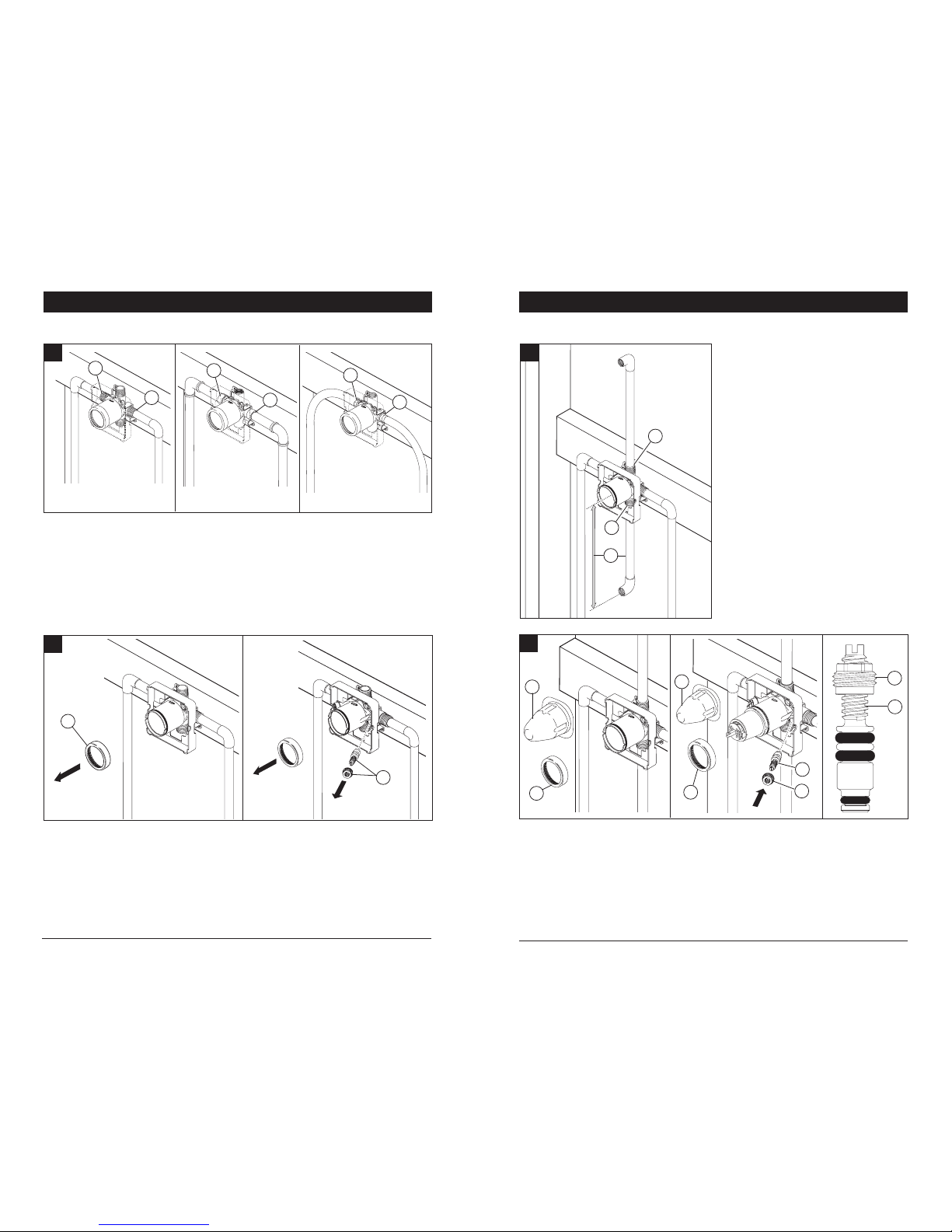
Connect top outlet (1) to shower pipe with
proper fittings. Connect bottom outlet (2) to tub
spout pipe with proper fittings. Pipe (3) between
valve body and tub spout must be a minimum of
1/2" (13 mm) copper pipe or 1/2" (13 mm) iron
pipe in a straight drop no less than 8" (203 mm)
but no more than 18" (457 mm) long with only
one iron pipe or copper 90 degree elbow to the
tub spout nipple. Do not use PEX tubing for
tub spout drop.
Prior to testing, remove cover (1) and bonnet
nut (2). Insert cartridge and tighten bonnet nut.
Turn cartridge stem counter clockwise until it will
no longer rotate. Plug both outlets with proper
fittings. Check for leaks. After testing, remove
cartridge, shower and/or tub spout plug and
flush system by slowly turning on water supply
to purge valve system of debris. After flushing,
reinstall cartridge (see page 6), bonnet nut
and cover. Install stops (3 & 4) in the models
with stops and set to full open. Note: Install
stops as follows: Thread nut (3) onto stem
(4) as shown. Then press stem and nut
assembly into body and tighten using a 3/8",
6 point, deep well socket. With a flat head
screwdriver, adjust stem clockwise to close
and counterclockwise to open.
Connect valve body to water supplies using
the proper fittings for your valve body type
(copper tubing, iron pipe or Pex). Note: (1) is
the cold inlet port and (2) is the hot inlet
port. If either of the two outlet ports is to be
unused, seal the port with a pipe plug.
Remove bonnet (1). Warning: Avoid
soldering at high temperatures.
Be sure stops (2) are removed from the
w/stops version before soldering. (Do not
install stops before soldering.)
If you are making a back to back or
reverse installation (hot on right and
cold on left) install the valve body as
described, but the water supply lines will
be reversed. Note: (1) is the hot inlet
port and (2) is the cold inlet port.
E.
F.
Copper Tubing Iron Pipe
Pex
C.
1
2
1
2
1
2
MultiChoice® Rough-In InstallationMultiChoice® Rough-In Installation
1
2
3
PRESSURE TESTING & FLUSHING THE INSTALLATION
1
2
1
2
4
3
4
5
3
4
D.
1
2
Page 6
13 / 14 Series Installation
2
Cartridge Installation
C.
Turn off water supplies. Remove
cover (1) and bonnet nut (2) from the
body, if necessary. If this is not a thin
wall mounting, the entire plasterguard (3)
may be removed.
For back to back or reverse installations
(hot on right and cold on left) insert the
cartridge with the “hot side” on the right.
If you are not making a reverse or back
to back installation skip this step and
continue with step 1C.
Slide bonnet nut (1) over the cartridge
and thread onto the body. Hand tighten
securely.
B.
Rotate the cartridge (1) so the words
“hot side” (2) appear on the left. Insert
cartridge into valve body as shown. Make
sure the cartridge tubes and O-rings (3)
are properly seated in holes at the base of
the body. Ensure the keys on the body are
fully engaged with the slots in the body (4).
Back to back Installation
Normal Installation (changes not required)
Reverse
Installation
Cold
Hot
1
4
4
2
3
1
6
13 / 14 Series Installation
3
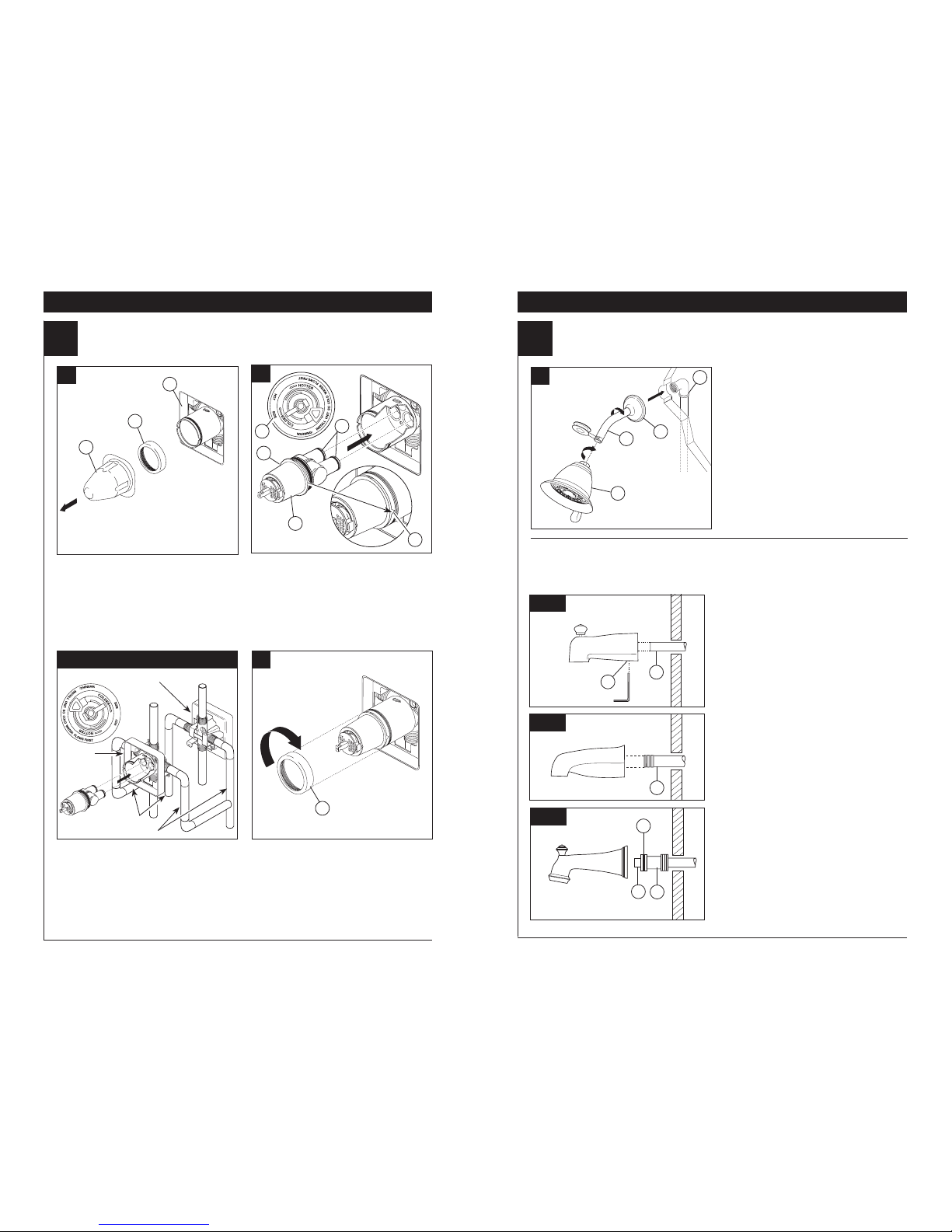
Showerhead and Tub Spout Installation
FOR SHOWERHEAD INSTALLATION:
Connect top outlet (1) to shower arm (2)
with proper fittings. To prevent damage
to finish on shower arm, insert wall end
of shower arm into shower flange (3)
before screwing arm into riser connection.
Thread showerhead (4) onto shower
arm. Apply plumber tape to pipe threads
on both ends. Do not overtighten
showerhead.
A.
3
2
1
Slip-On Installation
The copper tube (1) must be 1/2” nominal
copper. Important: If it is necessary to cut
the copper tube, the end must be chamfered free of burrs to prevent cutting or
nicking O-ring inside the spout. Slide spout
over copper tube flush with the finished tub
or wall surface. Tighten set screw (2), but
do not overtighten.
4
1
7
FOR TUB SPOUT INSTALLATION:
Refer to the installation instructions supplied with your spout. Do not connect deck mount
spouts to in-wall valves. Do not use hand showers connected in lieu of a tub spout to a
tub/shower valve. Do not use PEX tubing for tub spout drop.
B-1
B-2
B-3
Iron Pipe Installation
Install threaded pipe nipple (1) to extend
past finished wall. Apply plumber tape to
threads on pipe nipple and screw on
tub spout.
Copper Sweat Installation
Remove O-ring (1) from adapter (2). Solder
adapter to tube taking care to keep solder
away from O-ring groove. CAUTION: NO
SOLDER PERMITTED ON OUTSIDE
DIAMETER OF ADAPTER ADJACENT
TO O-RING GROOVE. Cut off tube (3) and
replace O-ring on groove of brass adapter.
Thread tub/spout onto adapter, taking care
not to damage O-ring, and hand tighten until
spout is firmly against finished wall and all
slack is taken up behind wall.
2
1
1
2
3
A.
1
2
3
Page 7

13 / 14 Series Installation
8
13 / 14 Series Installation
4
Adjusting the Rotational Limit Stop
IMPORTANT:
The Rotational Limit Stop is used to limit the
amount of hot water available such that, if set
properly, the user will not be scalded if the handle accidentally is rotated all the way to “hot”
when a person is showering or filling a tub. The
first position allows the LEAST amount of hot
water to mix with the cold water in the system.
In the first position the water will be the coldest
possible when the handle is turned all the way
to hot. As you move the Rotational Limit Stop
counterclockwise, you progressively add more
and more hot water in the mix. The last position
to the left will result in the greatest amount of
hot water to the mix, and the greatest risk of
scald injury if someone accidentally turns the
valve handle all the way to the hot side while
showering or filling a tub.
WARNING: In some instances, setting the
Rotational Limit Stop in the hottest position
(full counterclockwise) could result in scald
injury. It is necessary to adjust the Rotational Limit Stop so that the water coming out
of the valve will not scald the user when the
handle of the valve is rotated to the hot side.
• According to the majority of industry standards, the maximum allowable temperature of
the water exiting the valve is 120°F (Your local
plumbing codes may require a water temperature less than 120°F).
• The Rotational Limit Stop may need to be readjusted seasonally if the inlet water temperature changes. For example, during the winter,
the cold water temperature is colder than it is
during the summer which could result in varying outlet temperatures. A water temperature
for a comfortable bath or shower is typically
between 90°F - 110°F.
• Run the water so that the cold water is as
cold as it will get and hot water is as hot as
it will get. Place the handle on the stem (see
page 9, step 5D) and rotate the handle counterclockwise until the handle stops.
• Place a thermometer in a plastic tumbler
and hold in the water stream. If the water
temperature is above 120°F, the Rotational
Limit Stop must be repositioned clockwise to
decrease valve outlet water temperature to
be less than 120°F or to meet the requirements of your local plumbing codes.
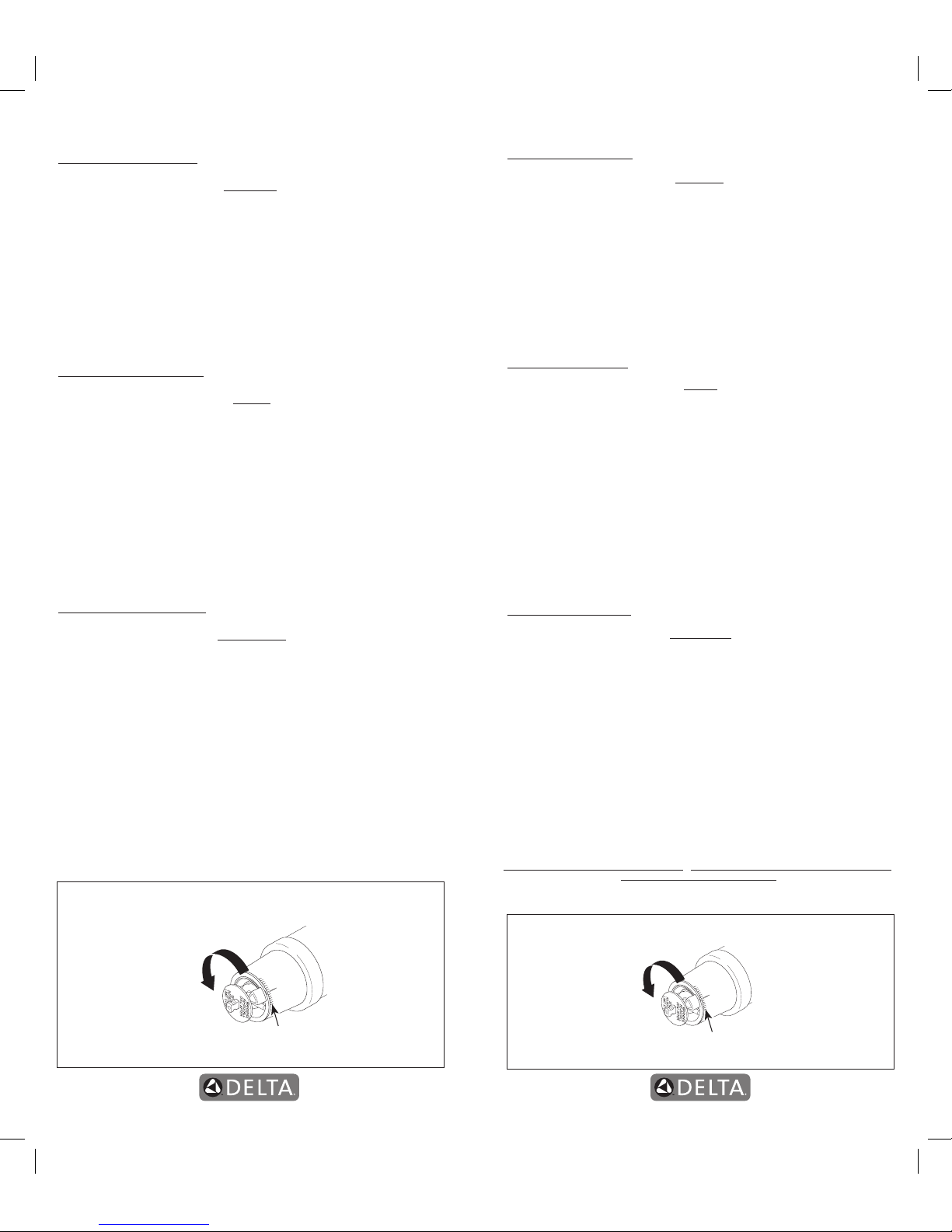
• To adjust the temperature of the water
coming out of the valve, pull the disc back to
a position where it is possible to remove the
Rotational Limit Stop and readjust the teeth
engagement position to the desired temperature. Clockwise will decrease the outlet
temperature, counterclockwise will increase
the outlet temperature. Temperature change
per tooth (notch) could be 4° - 16°F based on
inlet water conditions. Repeat as necessary.
Push disc until fully seated.
WARNING: Failure to re-install Disc after
setting Rotational Limit Stop could result
in scald injury.
• MAKE SURE COLD WATER FLOWS
FROM THE VALVE FIRST. MAKE SURE
WATER FLOWING FROM THE VALVE
AT THE HOTTEST FLOW POSSIBLE
DOES NOT EXCEED 120°F OR THE
MAXIMUM ALLOWED BY YOUR LOCAL
PLUMBING CODE.
1st Position
Hotter
Rotational Limit Stop
Stem
Disc
13 / 14 Series Installation
5
Trim Installation
C.
D.
A.
B.
Slide O-ring (1) over cartridge and the
bonnet nut (2). The O-ring, which acts as
a spacer to steady the sleeve, should rest
behind the bonnet nut.
If your model requires a spacer (1), insert
it into the sleeve (2) and push it to the
front. Slide the sleeve over the cartridge,
body and O-ring.
Secure the escutcheon (1) and backplate
(2) (if your model has one) to the bracket
(3) using the 2 screws provided (4). Do not
overtighten escutcheon screws.
Using an Allen wrench to secure the set
screw, install the handle onto the stem.
1
2
1
2
1
1
2
3
4
9
Page 8

Faucet leaks from tub spout/showerhead:
SHUT OFF WATER SUPPLIES.
Replace seats and springs–Repair
Kit RP4993. Check condition of lower O-rings and
replace if necessary RP14414. See Helpful Hints
1, 2, & 3.
If leak persists:
SHUT OFF WATER SUPPLIES.
Replace valve cartridge RP46074.
See Helpful Hints 1, 2, 3 & 5.
Unable to maintain constant water temperature:
Replace valve cartridge RP46074 or follow
instructions in Helpful Hints 1, 2, 4 & 5.
Helpful Hints:
1. Before removing valve cartridge assembly for any
maintenance, be sure to note the position of the
rotational limit stop on the cap. The valve cartridge
assembly must always be put back in the same
position. BE SAFE! After you have finished the
installation, turn on valve to make sure COLD
WATER FLOWS FIRST.
2. To remove valve cartridge from body, shut off
water supplies and remove handle and bonnet
nut. Do not pry the valve cartridge out of the body
with a screwdriver. Place handle on stem and rotate
counterclockwise approximately 1/4 turn after the stop
has been contacted. Lift valve cartridge out of body.
3. To remove seats and springs, remove valve
cartridge. Separate cap assembly from the
housing assembly by rotating the cap assembly
counterclockwise 90o (degrees). Separate cap
and housing assemblies. Remove seats and
springs and replace. Place the largest diameter
of the spring into the seat pocket first and then
press the tapered end of the seal over the spring.
Reassemble valve cartridge and replace in body
following instructions given in 1 above.
4. If the water in your area has lime, rust, sand or
other contaminants in it, your pressure balance
valve will require periodic inspection. The
frequency of the inspection will depend on the
amount of contaminants in the water. To inspect
valve cartridge remove it and follow the steps
in note 1 above. Turn the valve to the full mix
position and shake the cartridge vigorously. If
there is a rattling sound, the unit is functional and
can be reinstalled following instructions given in
note 1 above. If there is no rattle, replace valve
cartridge RP46074.
5. Push disc until fully seated. See page 8 for
more details.
To order replacement parts, visit
www.deltafaucet.com or call 1-800-354-3358
13/14 Series Maintenance
10
Cleaning and Care
Care should be given to the cleaning of this product. Although its finish is extremely durable, it can
be damaged by harsh abrasives or polish. To clean,
simply wipe gently with a damp cloth and blot dry
with a soft towel.
Warning: Scrubbing Bubbles® Bathroom Cleaner
and Lysol® Basin Tub and Tile Cleaner must not be
used on the clear knob handles and levers. Use of
these cleaners can result in cracked or severely
damaged handles. If overspray gets onto the
handles, immediately wipe them dry with a soft
cotton cloth
MultiChoice® 13/14
Grey
Off White
Longer
Lower Housing
Order RP46074 to
Replace Cartridge.
Old
Monitor® 1300/1400
White
Blue
or
Off White
Shorter Lower Housing
Order RP19804 to
Replace Cartridge.
White
Blue
Shorter Lower Housing
Order RP19804 to
Replace Cartridge.
New
Monitor® 1300/1400
Cartridge Summary Reference
Units shipped in March
2006 and after.
Replacement cartridges
shipped in July 2006
and after.
Units shipped before
March 2006.
Instrucciones para la
Instalación del Accesorio
para Válvulas MultiChoice
®
Manual para los
Propietarios
13 y 14
Series
Escriba aquí el número del modelo comprado.
ASME A112.18.1 / CSA B125.1
ASSE 1016
ESTA VÁLVULA CUMPLE O EXCEDE LAS
SIGUIENTES NORMAS:
ASME A112.18 1 / CSA B125.1 y ASSE 1016.
ADVERTENCIA: El instalador debe apostar
este systema/divisa para garantizar temperatura
maximo y seguro. Cualqueir cambio en el ajuste
puede subir la temperatura del agua de descarga
sobre el límite considerado seguro y puede
resultar en quemaduras de agua caliente.
AVISO PARA EL INSTALADOR: PRECAUCIÓN
– Como instalador de esta válvula, es su
responsabilidad de INSTALAR Y AJUSTAR
apropiadamente esta válvula como se describe
en las instrucciones, por lo tanto, debe haber
una persona para hacer los ajustes necesarios
del Tope del Límite Rotacional y del pomo
para la temperatura en el momento que se
haga la instalación y pueda necesitar ajustes
adicionales por los cambios estacionales
de la temperatura del agua. USTED DEBE
informarle al dueño/usuario sobre este
requisito siguiendo las instrucciones. Si usted
o el dueño/usuario no están seguros como
hacer estos ajustes apropiadamente, por favor
refiérase al Página 8 y si todavía no está seguro,
llámenos al 1-800-345-DELTA.
Después de hacer la instalación y el ajuste,
usted puede agregarle a la etiqueta de aviso
proporcionada, su nombre, el nombre de la
compañía y la fecha cuando ajustó el Tope del
Límite Rotacional y el pomo para la temperatura y
aplicar o fijar la etiqueta al dorso de la puerta del
gabinete más cercano y la etiqueta de aviso al
calentador de agua. Deje la Hoja de Instrucciones
para referencia del dueño/usuario.
ADVERTENCIA: Esta válvula de presión
balanceada y termostática está diseñada
para minimizar los efectos de los cambios
de temperatura de agua por causa de los
cambios de presión en el agua de entrada,
comúnmente causados por lavadoras de
platos, lavadoras de ropa, inodoros, y otros
aparatos por el estilo. Puede no proporcionar
protección de quemaduras de agua caliente
cuando hay alguna falla de otros aparatos
para el control de temperatura en otro
sitio en el sistema de plomería. También
no proporcionará protección si el tope del
límite rotacional y el pomo para el ajuste de
la temperatura no está apropiadamente fijo
o si cambia la temperatura del agua caliente
después de hacer los ajustes o si los cambios
del agua de entrada son por los cambios
estacionales.
ADVERTENCIA: No instale un aparato de corte
o cierre en cualquiera de las tomas de esta
válvula. Cuando este tipo de aparato cierra el
flujo de agua, puede hacer fallar la habilidad
de la válvula de balancear las presiones del
agua caliente y fría.
Contenido:
Garantías ........................................................................... Página 2
La instalación de la plomería MultiChoice® ......................... Páginas 3 - 5
Instrucciones de Instalación para la Series 13 / 14............. Páginas 6 - 9
Mantenimiento .................................................................... Página 10
Hoja resumen de referencia para el cartucho .................... Página 10
Para ordenar las piezas de repuesto, visítenos en www.deltafaucet.com
1
Usted puede necesitar
12/20/1272264 Rev. B
T
E
F
L
O
N
Page 9

2
CIERRE LOS SUMINISTROS DE AGUA.
Considere el tipo y el grosor de su pared
terminada antes de colocar su placa trasera
de acoplamiento de las tuberías. Instale la
pieza (1) de manera que la superficie de la
pared terminada quede al ras con el frente
del protector de yeso (2) ± 3/8". Nota: Para
con los modelos de las paradas (3), el
protector del yeso debe ser el rubor
Instalación de la plomería MultiChoice®
1
A.
B.
La distancia (1) del empalme de tuberías
(2) al frente del protector de yeso es 2.8"
(71 mm). La distancia (3) del empalme de
tuberías (2) al frente de la tuerca tapa o
capuchón es 3.9" (99 mm).
rasante o secundario el 3/8”a la pared
acabada. Instale la pieza usando los dos
agujeros de instalación del acoplamiento
(4) en el soporte. Nota: Quite la cubierta
(5) para tener acceso a los agujeros
de instalación. Cuando esté haciendo la
instalación, asegúrese que la palabra
“UP” (6) quede arriba de la válvula.
Si usted está trabajando en una pared
delgada, asegúrese de tener un protector
de yeso detrás de la pared, si no la pared
siempre deberá estar al ras con el frente
del protector de yeso.
1
2
6
5
4
4
1
3
2
3
3
© 2012 Masco Corporación de Indiana
Piezas y acabado
Todas las piezas (excepto las piezas electrónicas y las pilas) y los acabados de esta llave de agua Delta® están
garantizados al consumidor comprador original de estar libres de defectos en material y fabricación durante el
tiempo que el comprador original posea la vivienda en la que la llave de agua fue originalmente instalada o,
para los consumidores comerciales, durante 5 años a partir de la fecha de compra.
Componentes electrónicos y pilas (si aplicable)
Todas las piezas (salvo las pilas), si hay, de esta llave de agua Delta® están garantizadas al consumidor
comprador original de estar libres de defectos en materiales y fabricación durante 5 años a partir de la fecha de
compra o, para los usuarios comerciales, por un año a partir de la fecha de compra. No se garantizan las pilas.
Delta Faucet Company reemplazará, SIN CARGO, durante el período de garantía aplicable, cualquier pieza o
acabado que pruebe tener defectos de material y/o fabricación bajo la instalación, uso y servicio normal. Si la
reparación o su reemplazo no es práctico, Delta Faucet Company tiene la opción de reembolsarle su dinero por
la cantidad del precio de compra a cambio de la devolución del producto. Estos son sus únicos recursos.
Delta Faucet Company recomienda que use los servicios de un plomero profesional para todas las instalaciones
y reparaciones. También le recomendamos que utilice sólo las piezas de repuesto or iginales de Delta®.
Delta Faucet Company no será responsable por cualquier daño a la llave de agua que resulte del mal uso,
abuso, negligencia o mala instalación o mantenimiento o reparación incorrecta, incluyendo el no seguir los
cuidados aplicables y las instrucciones de limpieza.
Las piezas de repuesto se pueden obtener llamando al número correspondiente más abajo, o escribiendo a:
En los Estados Unidos y México: En Canadá:
Delta Faucet Company Masco Canada Limited, Plumbing Group
Product Service Technical Service Centre
55 E. 111th Street 350 South Edgeware Road
Indianapolis, IN 46280 St. Thomas, Ontario, Canada N5P 4L1
1 800 345 DELTA (3358) 1 800 345 DELTA (3358)
customerservice@deltafaucet.com customerservice@mascocanada.com
La prueba de compra (recibo original) del comprador original debe ser disponible a Delta Faucet Company para
todos los reclamos a menos que el comprador haya registrado el producto con Delta Faucet Company. Esta
garantía le aplica sólo a las llaves de agua de Delta® fabricadas después del 1 de enero 1995 e instaladas en
los Estados Unidos de América, Canadá y México.
DELTA FAUCET COMPANY NO SE HACE RESPONSABLE POR CUALQUIER DAÑO ESPECIAL, INCIDENTAL
O CONSECUENTE (INCLUYENDO LOS GASTOS DE MANO DE OBRA) POR EL INCUMPLIMIENTO DE
CUALQUIER GARANTÍA EXPRESA O IMPLÍCITA DE LA LLAVE DE AGUA. Algunos estados/provincias
no permiten la exclusión o limitación de daños especiales, incidentales o consecuentes, por lo que estas
limitaciones y exclusiones pueden no aplicarle a usted. Esta garantía le otorga derechos legales. Usted también
puede tener otros derechos que varían de estado/provincia a estado/provincia.
Esta es la garantía exclusiva por escrito de Delta Faucet Company y la garantía no es transferible.
Si usted tiene alguna pregunta o inquietud acerca de nuestra garantía, por favor, vea nuestra sección de preguntas
frecuentes FAQ sobre la garantía en www.deltafaucet.com, también puede enviarnos un correo electrónico a
customerservice@deltafaucet.com o llámenos al número que le corresponda anteriormente incluido.
Garantía Limitada de las Llaves de Agua (grifos) Delta®
Page 10

Conecte el cuerpo de la válvula a los suministros de agua usando los accesorios apropiados para el tipo de su válvula (tubería de
cobre, hierro o Pex). Nota: (1) es la entrada
del agua fría y el (2) es la entrada del agua
caliente. Si no va a usar alguna de las dos
entradas de agua, séllela con un tapón
de tubería.
Si está hacienda una instalación dorso
con dorso o a la inversa (caliente en la
derecha y fría en la izquierda) instale el
cuerpo de la válvula como se describe
arriba, pero coloque al inverso las líneas
de suministro de agua. Nota: (1) es
la entrada de agua caliente (2) es la
entrada del agua fría.
Tubería de
Cobre
Hierro
Pex
Instalación de la plomería MultiChoice®
4
Conecte la salida de arriba (1) a la tubería de
la regadera con los accesorios apropiados.
Conecte la salida de abajo (2) a la tubería
del surtidor de la bañera con los accesorios
apropiados. La tubería (3) entre el cuerpo de
la válvula y el de la bañera debe ser de un
mínimo de 1/2" (13 mm) de tubería de cobre
ó 1/2" (13 mm) de tubería de hierro en caída
recta no menos de 8" (203 mm) pero no más
de 18" (457 mm) de largo a la entrerrosca del
surtidor de la bañera y con sólo un codo de 90
grados, de tubería de hierro o cobre. No use la
tubería PEX como tubería entre la válvula y
el surtidor de la bañera.
E.
Instalación de la plomería MultiChoice
®
1
2
3
5
D.
Quite el capuchón (1). Advertencia: Evite
soldar a temperaturas altas.
Sea seguro que las válvulas apagadas
(2) están quitadas de la versión con las
paradas antes de soldar. (no instale las
válvulas apagadas antes de soldar.)
1
2
C.
1
2
1
2
1
2
Antes de probarlo, retire la tapa (1) y la tuerca
del capuchón (2). Inserte el cartucho y apriete
la tuerca del capuchón. Gire la espiga del
cartucho hacia la derecha hasta que ya no gire
más. Conecte las dos salidas con los accesorios
adecuados. Revise si hay fugas. Después de la
prueba, retire el cartucho, el tapón del surtidor de
la regadera y/o bañera y deje correr el agua por
las tuberías lentamente abriendo el suministro
de agua para purgar el sistema de válvulas de
residuos. Después de descargar el agua, vuelva
a instalar el cartucho (consulte la página 6), la
tuerca tapa y la cubierta. Instale los topes (3 y 4)
en los modelos con topes y abra completamente.
Nota: Instale las paradas en con la versión de
las válvulas apagadas como sigue: Rosque
la tuerca (6) en el vástago (7) según lo
demostrado. Después presione el montaje del
vástago y de tuerca en cuerpo (8) y apriete con
un 3/8”, 6 puntos, zócalo bien profundo. Con un
destornillador principal plano, ajuste el vástago
a la derecha al cierre y a la izquierda abrirse.
F.
PRUEBA DE PRESIÓN Y LIMPIEZA DE LA INSTALACIÓN
1
2
1
2
4
3
3
4
Page 11

Instalación de las Series 13 / 14
2
Instalación del Cartucho
C.
En las instalaciones dorso con dorso o al
reverso (caliente en la derecha y fría en
la izquierda) introduzca el cartucho con la
inscripción “hot side” a la derecha. Si usted
no está instalando al reverso o dorso con
dorso omita este paso y continúe con el
paso 1C.
Deslice la tuerca tapa (1) sobre el cartucho
y enrosque en el cuerpo de la válvula.
Apriete a mano bien.
B.
Gire el cartucho (1) de manera que las palabras
‘hot side’ (lado caliente) (2) aparezcan a la
izquierda. Introduzca el cartucho en la válvula
como se muestra. Asegúrese que los tubos del
cartucho y los aros-O (3) estén apropiadamente
sentados en los agujeros en la base del cuerpo
de la válvula. Asegúrese que la parte dentada en
el cuerpo de la pieza encaje completamente en
las muescas de éste (4).
Instalación de Espalda a Espalda
Instalación Normal (No serequerá cambios)
Instalación
Invertido
Fría
Caliente
1
4
4
2
3
1
6
PARA LAS INSTALACIONES DE LAS
CABEZAS DE REGADERA: Conecte
la toma de salida de agua superior (1) al
brazo de la regadera (2) con los accesorios
apropiados. Para prevenir daño al acabado
del brazo de la regadera, introduzca el
extremo que va hacia la pared del brazo
de la regadera dentro del reborde (3) antes
de atornillar el brazo en la conexión de la
tubería vertical. Aplique cinta para plomero
los enrosques de la tubería. No apriete
demasiado la cabeza de la regadera (4).
A.
3
2
1
Instalación de las Series 13 / 14
3
Instalación de la Cabeza de la Regadera y el Surtidor de la Bañera
7
Instalación deslizable
El tubo de cobre (1) debe ser de1/2" de cobre
nominal. Importante: Si es necesario cortar el
tubo de cobre, el extremo debe biselarse que
quede libre de rebabas para prevenir cortar
o mellar el aro O dentro del tubo de cobre.
Deslice el surtidor sobre el tubo de cobre al
ras con la bañera o la superficie de la pared
acabada. Apriete el tornillo de ajuste (2), pero
no apriete demasiado.
1
PARA LA INSTALACIÓN DEL SURTIDOR DE LA BAÑERA: Refiérase a las instrucciones
para la instalación suministradas con su surtidor. No conecte los surtidores para las instalaciones en las superficies horizontales en las válvulas dentro de las paredes. No use las regaderas
de mano en vez de un surtidor de bañera conectado a una válvula de bañera/regadera. No use
la tubería PEX como tubería entre la válvula y el surtidor de la bañera.
B-1
B-2
B-3
Instalación de la tubería de Hierro
IInstale una entrerrosca de tubo enroscado
de 1/2” (13 mm) (1) para extenderse por
delante de la pared acabada. Aplique cinta
para plomero las roscas en la entrerrosca de
tubo y atornille el surtidor de la bañera.
Instalación de Soldadura de Cobre
Quite el aro O (1) del adaptador (2). Suelde el
adaptador al tubo asegurando de mantener
la soldadura lejos de las muesca del aro O.
AVISO: NO SE PERMITE SOLDAR EN EL
DIAMETRO EXTERIOR DEL ADAPTADOR
ADJUNTO A LA MUESCA DEL ARO O. Corte
el tubo (3) y coloque otra vez el aro O en la
muesca del adaptador de latón. Atornille la
bañera/surtidor al adaptador, asegurando no
dañar el aro O, y apriete a mano bien hasta que
el surtidor quede firmemente contra la pared
acabada y no quede flojo detrás de la pared.
2
1
1
2
3
4
A.
Cierre los suministros de agua. Retire
la cubierta (1) y la tuerca tapa (2) del
cuerpo, si es necesario. Si no es una instalación en pared delgada, puede quitar
el protector de yeso (3) completo.
1
2
3
Page 12

8
Instalación de las Series 13 / 14
4
El Ajuste del Tope que Limita la Rotación
IMPORTANTE:
El Ajuste del Tope que Limita la Rotación
se usa para limitar la cantidad de agua
caliente disponible de manera que, si
ajustado apropiadamente, el usuario no se
quemará si la manija se gira accidentalmente
completamente a “hot” (“caliente”) cuando
una persona se está duchando o llenando
la bañera. La primera posición permite la
cantidad MÍNIMA de agua caliente mixta con
la fría en el sistema. En la primera posición
el agua estará lo más fría posible cuando
la manija se gira completamente a caliente.
Mientras que mueve el Ajuste del Tope que
Limita la Rotación en dirección contrario a
las manecillas del reloj, progresivamente
aumentará el agua caliente en la mezcla
más y más. La última posición a la izquierda
es la de mayor cantidad de agua caliente en
la mezcla, y tiene el mayor riesgo de lesión
por quemadura si alguien accidentalmente
abre la manija de la válvula completamente
a la posición caliente mientras que se baña o
llena la bañera.
ADVERTENCIA: En algunos casos,
ajustar el Ajuste del Tope que Limita la
Rotación en la posición más caliente
(completamente en el sentido contrario
a la dirección de las manecillas del reloj)
puede resultar en lesión por quemadura.
Es necesario ajustar el Tope que Limita
la Rotación de manera que el agua que
sale de la válvula no queme o escalde al
usuario cuando la manija de la válvula se
gira al lado caliente.
De acuerdo con la mayoría de los estándares
de la industria, la temperatura máxima
permisible del agua que sale es 120°F (Sus
códigos locales de plomería pueden requerir
una temperatura de agua menor de 120°F).
El Tope que Limita la Rotación puede
requerir el ajuste estacional si la temperatura
del agua cambia. Por ejemplo, durante el
invierno, la temperatura del agua fría es más
fría que durante el verano resultando en temperaturas variadas en el agua de salida. Una
temperatura de agua para un baño o ducha
confortable típicamente es entre 90°F - 110°F.
Deje que el agua corra de manera que el agua
fría esté lo más fría posible y la caliente esté
lo más caliente posible. Coloque la manija en
la espiga (vea la página 9, paso 5D) y gire la
manija en dirección contraria a las manecillas
del reloj hasta que la manija pare.
Coloque el termómetro en un vaso plástico y
sosténgalo bajo el chorro de agua. Si la temperatura de agua está por encima de 120°F el
tope que limita la rotación debe ajustarse otra
vez moviéndolo en sentido de las manecillas
del reloj para reducir la temperatura del agua
de salida de la válvula a menos de 120°F o
para que cumpla con los requisitos de sus
códigos locales de plomería.
Para ajustar la temperatura del agua que
sale de la válvula, hale el disco otra vez a la
posición donde se puede remover el Tope
del Límite Rotacional y reajuste el engranaje
de los dientes a la posición para la temperatura deseada. Al mover en dirección de las
manecillas del reloj reducirá la temperatura
del agua de salida, y al contrario aumentará la
temperatura del agua de salida. El cambio de
temperatura por cada diente (muesca) puede
ser de 4°F-16°F dependiendo de la condición
del agua de entrada. Si es necesario repítalo.
Presione el disco hasta que está asentado
completamente. ADVERTENCIA: Si no rein-
stala el Disco después de hacer el ajuste
del Tope del Límite Rotacional pudiera
escaldarse con agua demasiado caliente.
ASEGÚRESE QUE EL AGUA FRÍA FLUYA DE
LA VÁLVULA PRIMERO. ASEGÚRESE QUE
EL AGUA QUE FLUYE DE LA VÁLVULA EN LA
POSICIÓN MÁS CALIENTE POSIBLE NO EXCEDA 120°F O EL MÁXIMO PERMITIDO POR
SUS CÓDIGOS LOCALES DE PLOMERÍA.
Posición Primera
Más
Caliente
Unidad
del Vástago
Tope de Limite de Girar
Disco
Instalación de las Series 13 / 14
5
Instalación Final
C.
D.
A.
B.
Deslice el aro O (1) sobre el cartucho y la
tuerca tapa (2). El aro O, el cual funciona
como un separador para estabilizar la manga,
debe quedar apoyado en la tuerca tapa.
Si su modelo requiere un separador (1),
insértelo en la manga (2) y empújelo hacia el
frente. Deslice la manga sobre el cartucho,
el cuerpo de la pieza y el aro O.
Fije la roseta con orificio (1) y la placa de
atrás (2) (si su modelo tiene una) al soporte
(3) usando los 2 tornillos suministrados (4).
No apriete demasiado los tornillos de la
roseta.
Instale la manija en la espiga, usando una
llave Allen para fijar el tornillo de ajuste.
1
2
1
2
1
1
2
3
4
9
Page 13

Tenga cuidado al ir a limpiar este producto.
Aunque su acabado es sumamente durable,
puede ser afectado por agentes de limpieza o
para pulir abrasivos. Para limpiar su llave, simplemente frótela con un trapo húmedo y luego
séquela con una toalla suave.
Limpieza y Cuidado de su Llave
¡ADVERTENCIA! No se puede usar
SCRUBBING BUBBLES® BATHROOM
CLEANER o LYSOL® BASIN TUB AND TILE
CLEANER en las manijas transparentes. El
uso de estos productos pueden resultar en manijas rajados o severamente dañados. Si estos productos caen sobre la manija, séquelo inmediatamente con una toalla de algodón suave.
La llave tiene fugas de agua en la
salida de tina/cabeza deregadera–
CIERRE LOS SUMINISTROS DE AGUA.
Reemplace Asientos y Resortes–Equipo de
Reparaciones RP4993 Verifica el condición de los
anillos “O” más bajo y repongalos si será necesario
RP14414. Vea Sugerencias Utiles 1, 2, y 3.
Si la fuga de agua persiste–
CIERRE LOS SUMINISTROS DE AGUA.
Reemplace la válvula de cartucho RP46074.
Vea Sugerencia Utiles 1, 2, 3 y 5.
No se puede mantener temperatura de
agua constante:
Reemplace la válvula de cartucho RP46074 o sigue
los instrucciones en Sugerencias Utiles 1, 2, 4 y 5.
Sugerencia Utiles:
1. Antes de remover el ensamble del cartucho de
la válvula para hacerle cualquier servicio, fíjese en
la posición del tope del límite rotacional ubicado en
la tapa. Siempre se debe reponer el ensamble de
cartucho de válvula en el mismo posición. TENGA
CUIDADO después de cumplir el instalación dele
vuelta a la válvula para asegurar que AGUA FRIA
SALGA PRIMERO.
2. Para quitar el cartucho de válvula del cuerpo, cierre
los suministros de agua y quite el maneral y bonete.
No se debe quitar el cartucho de válvula del cuerpo
con atornillador. Ponga el maneral encima el vástago y
giralo en el sentido contrario al de las agujas del reloj
aproximado 1/4 vuelta. Levanta el cartucho de válvula
aguera el cuerpo.
3. Para quitar los asientos y resortes, quite el
cartucho de válvula, (vea arriba). Separa ensamble
de botón de ensamble de caja girando el botón
90o en el sentido contrario al de las agujas del
reloj. Separa ensambles de botón y caja. Quite los
asientos y resortes y ponga los asientos y resortes
nuevos. Ponga primero el diámetro mas grande del
resorte adentro la bolsa del asiento y luego apreta
el remate ahusado del sello hacia arriba el resorte.
Reensembla el cartucho de válvula y repongalo en el
cuerpo siguendo los instrucciones en nota 1 arriba.
4. Si la agua en su area contiene cal, orín, arena
o otros contaminamientos, su válvula de equilibrio
de presión requerá inspecciones periódico. La
frequencía de los inspecciones depende en el
tamaño de contaminamientos en la agua. Para
inspectar el cartucho, quite el cartucho, sigue los
pasos apuntado en nota 1 arriba. Dele vuelta al
válvula hasta el posición completamente mixto
y sacude el cartucho riguroso. Si hay traqueteo,
funciona el unidad y se puede reinstalar siguendo
nota 1 de arriba. Si no hay traqueteo, reemplace la
válvula de cartucho RP46074.
5. Presione el disco hasta que está asentado
completamente. Vea la página 8 para más detalles.
Para ordenar las piezas de repuesto, visítenos
en www.deltafaucet.com
Mantenimiento de las Series 13 / 14
10
MultiChoice® 13/14
Gris
Blancuzco
Bastidor más Largo
Ubicado más Abajo
Ordene el Repuesto RP46074
para cambiar el cartucho.
Viejo
Monitor® 1300/1400
Blanco
Azul o
Blancuzco
Más corto Más abajo Bastidor
Ordene el Repuesto RP19804
para cambiar el cartucho.
Blanco
Azul
Nuevo
Monitor® 1300/1400
Hoja resumen de referencia para el cartucho
Unidades enviadas en
Marcha de 2006 y después.
Los cartuchos del reem-
plazo enviaron en julio de
2006 y después.
Unidades enviadas antes de
Marcha de 2006.
Ordene el Repuesto RP19804
para cambiar el cartucho.
Más corto Más abajo Bastidor
Instructions d’installation
Finition de la soupape
MultiChoice
®
Guide d’utilisation
13 et 14
Séries
Inscrivez le numéro de modèle ici.
ASME A112.18.1 / CSA B125.1
ASSE 1016
®
®
U
P
C
Table des matières
Garanties ............................................................................ Page 2
Installation de la plomberie brute MultiChoice® .................. Pages 3 - 5
Instructions d’installation - Séries 13 et 14 ......................... Pages 6 - 9
Maintenance ....................................................................... Page 10
Fiche de référence sommaire de la cartouche ................... Page 10
Pour commander des pièces de rechange, visitez www.deltafaucet.com
1
Articles dont vous pouvez avoir besoin:
12/20/12
72264 Rev. B
Ce robinet satisfait aux exigences des normes
ASME A112.18.1/CSA B125.1 et ASSE 1016 ou
les surpasse.
ATTENTION: L’installateur doit régler l’appareil
pour que la température maximale de l’eau chaude
soit sans danger. Toute modification des réglage
peut entraîner une élévation de la température à
la sorite du robinet au delà de la température sans
danger et pourrait causer un échaudage.
AVIS À L’INSTALLATEUR : ATTENTION! – En
qualité d’installateur, vous êtes tenu
d’INSTALLER et de RÉGLER ce robinet
conformément aux instructions. Ce robinet ne
s’adapte pas automatiquement aux fluctuations
de la température de l’eau d’alimentation. Par
conséquent, il faut régler la butée limitatrice de
température ou le bouton de température au
moment de l’installation et il peut être
nécessaire de faire de nouveaux réglages par
la suite en raison des fluctuations saisonnières
de la température de l’eau. VOUS DEVEZ
informer le propriétaire ou l’utilisateur de cette
exigence. En cas de doute quant à la marche à
suivre pour faire ces réglages, veuillez
consulter page 8 si un doute persiste, et si
cette incertitude persiste, appelez-nous au
1-800-345-DELTA.
Après avoir terminé l’installation et le réglage, vous
devez inscrire, sur l’étiquette de mise en garde
fournie, votre nom, le nom de votre entreprise et la
date à laquelle vous avez réglé la butée limitatrice
de température ou le bouton de température, puis
fixer l’étiquette à l’endos de la porte de la coiffeuse.
Vous devez également fixer l’étiquette
d’avertissement au chauffe-eau. Veuillez laisser ce
feuillet d’instructions au propriétaire ou à
l’utilisateur pour qu’il puisse le consulter
au besoin.
MISE EN GARDE – Ce robinet thermostatique
à équilibrage de pression pour baignoire est
conçu pour limiter les effets des fluctuations de
température de l’eau causées par les variations
de la pression d’alimentation attribuables au
fonctionnement d’un lave-vaisselle, d’une
machine à laver, d’un cabinet d’aisances ou
d’un autre appareil qui consomme de l’eau.
Il peut ne pas protéger l’utilisateur contre
l’échaudage en cas de défectuosité d’un autre
dispositif de régulation de la température,
si le réglage de la butée limitatrice de haute
température ou du bouton de température
est mauvais, si la température de l’eau
chaude a été modifiée après que les réglages
ont été effectués ou si la température de
l’eau d’alimentation a changé en raison du
changement de saison.
MISE EN GARDE – N’installez pas de dispositif
d’arrêt sur une sortie quelconque de ce robinet.
En interrompant l’écoulement de l’eau, ce
dispositif peut empêcher le robinet d’équilibrer
les pressions d’eau chaude et d’eau froide.
T
E
F
L
O
N
Page 14

2
INTERROMPEZ L’ALIMENTATION EN EAU.
Déterminez le type de la paroi et son
épaisseur totale avant de placer la plaque
arrière. Installez le corps (1) de sorte que
la surface finie de la paroi soit à égalité
avec l’avant du protecteur (2) ± 3/8 po.
Note : Pour avec des modèles d’arrêts
(3), la garde de plâtre doit être l’éclat
affleurant ou secondaire 3/8 po au
Installation de la plomberie brute MultiChoice
®
1
mur fini. Installez le corps utilisez les
deux trous (4) de la fixation qui donnent
sur l’entretoise. Note : Enlevez le cou-
vercle (5) pour découvrir les trous de
montage. Au moment de l’installation,
assurez-vous que le mot « UP » (6) sur
le dessus du corps de robinet se trouve
en haut.
3
A.
B.
1
2
6
5
4
4
1
3
2
3
Distance (1) from the stringer (2) to the
front of the plasterguard is 2.8" (71 mm).
Distance (3) from the stringer (2) to the
front of the bonnet is 3.9" (99 mm).
If a thin wall is used, be sure to have the
plasterguard behind the wall, otherwise
the wall should always be flush with the
front of the plasterguard. See instruction
on the bag for thin wall mounting.
© 2012 Division de Masco Indiana
Pièces et finis
Toutes les pièces (à l’exception des composants électroniques et des piles) et tous les finis de ce robinet Delta®
sont protégés contre les défectuosités du matériau et les vices de fabrication par une garantie qui est consentie
au premier acheteur et qui demeure valide tant que celui-ci demeure propriétaire de la maison dans laquelle le
robinet a été installé. Dans le cas d’une utilisation commerciale, la garantie est de 5 ans à compter de la date
d’achat.
Composants électroniques et piles (le cas échéant)
Si ce robinet Delta® comporte des composants électroniques, ces composants (à l’exception des piles) sont
protégés contre les défectuosités du matériau et les vices de fabrication par une garantie consentie au premier
acheteur qui est d’une durée de 5 ans à compter de la date d’achat. Dans le cas d’une utilisation commerciale, la
garantie est d’un an à compter de la date d’achat. Aucune garantie ne couvre les piles.
Delta Faucet Company remplacera, GRATUITEMENT, pendant la période de garantie applicable, toute pièce ou
tout fini qui présentera une défectuosité du matériau et/ou un vice de fabrication pour autant que le robinet ait été
installé, utilisé et entretenu normalement. S’il est impossible de réparer ou de remplacer le robinet, Delta Faucet
Company pourra décider de rembourser le prix d’achat du produit pour autant que celui-ci lui soit retourné. Il
s’agit de vos seuls recours.
Delta Faucet Company recommande de confier l’installation et la réparation à un plombier professionnel. Nous
vous recommandons également d’utiliser uniquement des pièces de rechange authentiques Delta®.
Delta Faucet Company se dégage de toute responsabilité à l’égard des dommages causés au robinet en raison
d’un mauvais usage, d’un usage abusif, de la négligence ou de l’utilisation d’une méthode d’installation, de
maintenance ou de réparation incorrecte ou inadéquate, y compris les dommages résultant du non-respect des
instructions de nettoyage et d’entretien applicables.
Pour obtenir des pièces de rechange, veuillez appeler au numéro applicable ci-dessous ou écrire à l’adresse
applicable ci-dessous.
Aux États-Unis et au Mexique : Au Canada:
Delta Faucet Company Masco Canada Limited, Plumbing Group
Product Service Technical Service Centre
55 E. 111th Street 350 South Edgeware Road
Indianapolis, IN 46280 St. Thomas, Ontario, Canada N5P 4L1
1-800-345-DELTA (3358) 1-800-345-DELTA (3358)
customerservice@deltafaucet.com customerservice@mascocanada.com
La preuve d’achat (reçu original) du premier acheteur doit être présentée à Delta Faucet Company pour toutes
les demandes en vertu de la garantie, sauf si le produit a été enregistré auprès de Delta Faucet Company. La
présente garantie s’applique uniquement aux robinets Delta® fabriqués après le 1er janvier 1995 et installés aux
États-Unis d’Amérique, au Canada et au Mexique.
DELTA FAUCET COMPANY SE DÉGAGE DE TOUTE RESPONSABILITÉ À L’ÉGARD DES DOMMAGES
PARTICULIERS, CONSÉCUTIFS OU INDIRECTS (Y COMPRIS LES FRAIS DE MAIN-D’OEUVRE) QUI
POURRAIENT RÉSULTER DE LA VIOLATION D’UNE GARANTIE IMPLICITE OU EXPLICITE QUELCONQUE
SUR LE ROBINET. Dans les États ou les provinces où il est interdit de limiter ou d’exclure la responsabilité à
l’égard des dommages particuliers, consécutifs ou indirects, les limites et les exclusions susmentionnées ne
s’appliquent pas. La présente garantie vous donne des droits précis qui peuvent varier selon l’État ou la province
où vous résidez.
La présente garantie écrite est la garantie exclusive offerte par Delta Faucet Company et elle n’est pas
transférable.
Si vous avez des questions ou des préoccupations en ce qui concerne notre garantie, veuillez consulter la page
Warranty FAQs à www.deltafaucet.com, faire parvenir un courriel à customerservice@deltafaucet.com ou nous
appeler au numéro applicable.
Garantie limitée des robinets Delta
®
Page 15

ESSAI SOUS PRESSION ET RINÇAGE DE L’INSTALLATION
Raccorder le corps de robinet à la tuyauterie
(cuivre, fer ou Pex). Note : (1) correspond à
l’entrée d’eau froide et (2) correspond à
l’entrée d’eau chaude. Si l’une des entrées
est inutilisée, obturez-la avec un bouchon.
Dans le cas d’une installation dos à dos
ou inversée (eau chaude à droite et eau
froide à gauche), installez le corps de
robinet de la manière indiquée ci-dessus.
La tuyauterie d’alimentation doit toutefois
être inversée. Note : (1) est l’entrée d’eau
chaude et (2) est l’entrée d’eau froide.
Installation de la plomberie brute MultiChoice
®
4
À l’aide des raccords appropriés, raccordez
l’orifice supérieur (1) au tuyau de la douche
et l’orifice inférieur (2) au tuyau du bec de
baignoire. Le corps de robinet doit être relié au
bec de baignoire par un tuyau de cuivre d’au
moins 1/2 po (13 mm) ou un tuyau de fer d’au
moins 1/2 po (13 mm). Ce tuyau (3) doit être
droit et il doit avoir une longueur d’au moins 8
po (203 mm) et d’au plus 18 po (457 mm); il
doit être relié au tuyau du bec de baignoire par
un seul coude à 90 degrés en cuivre ou en fer.
N’utilisez pas de tube PEX pour raccorder
le bec.
E.
Installation de la plomberie brute MultiChoice
®
1
2
3
5
Enlevez le chapeau (1). Mise en garde :
évitez le brasage à haute température.
Soyez sûr que des valves coupées (2) sont
enlevées de la version avec des arrêts
avant la soudure. (n’installez des valves
coupées avant la soudure.)
Cuivre Fer
Pex
C.
1
2
1
2
1
2
D.
1
2
Avant d’effectuer l’essai, enlevez le couvercle (1) et
l’écrou-chapeau (2). Insérez la cartouche et serrez
l’écrou-chapeau. Tournez la tige de la cartouche
dans le sens anti-horaire jusqu’à ce qu’elle ne
tourne plus. Obturez les deux sorties à l’aide des
bouchons appropriés. Vérifiez l’étanchéité. Après
avoir effectué la vérification, enlevez la cartouche
ainsi que le bouchon de la sortie de la douche
et/ou du bec de bain, puis rincez l’installation en
rétablissant lentement l’alimentation en eau pour
évacuer les corps étrangers. Une fois le rinçage
terminé, reposez la cartouche (consultez la page
6), l’écrou-chapeau et la coiffe. Sur les modèles
qui en sont munis, installez les robinets d’arrêt
(3 et 4) et ouvrez-les.
Note : Installez les arrêts dans avec la version
de valves coupées comme suit : Filetez l’écrou
(3) sur la tige (4) comme montré. Alors serrez
l’ensemble de tige et d’écrou dans le corps et
serrez en utilisant un 3/8 po, 6 points, douille
bonne profonde. Avec un tournevis principal
plat, ajustez la tige dans le sens des aiguilles
d’une montre sur la fin et s’ouvrir dans le sens
contraire des aiguilles d’une montre.
F.
1
2
1
2
4
3
3
4
Page 16

Installation – Séries 13 et 14
3
Installation de la pomme de douche et du bec de baignoire
INSTALLATION DE LA POMME DE
DOUCHE : Raccordez la sortie supérieure
(1) au tuyau d’alimentation de la pomme de
douche (2) à l’aide des raccords appropriés.
Pour éviter d’abîmer le fini du tuyau de la
pomme de douche, introduisez le côté « mur
» de celui-ci dans la collerette (3) avant de
le visser dans le raccord du tuyau vertical.
Appliquez du ruban de plomberie sur les
filets. Vissez la pomme de douche (4) sur le
tuyau. Appliquez du ruban de plomberie sur
les filets. Prenez garde de serrer la pomme
de douche excessivement.
A.
3
2
1
4
7
Installation d’un bec coulissant
Le tube de cuivre (1) doit avoir un diamètre
nominal de1/2 po. Important : Si vous devez
couper le tube de cuivre, chanfreinez son
extrémité de sorte qu’elle ne risque pas
d’endommager le joint torique à l’intérieur du
bec. Faites glisser le bec sur le tube de cuivre
de sorte qu’il s’appuie contre la surface finie
de la baignoire ou du mur. Serrez la vis de
calage (2), mais prenez garde de la serrer
excessivement.
1
INSTALLATION DU BEC DE BAIGNOIRE : Consultez les instructions d’installation fournies avec
le bec. Ne raccordez pas à une soupape murale à un bec conçu pour être monté sur une plage. Ne
raccordez pas une douche à main à la sortie d’un robinet de baignoire-douche prévue pour un bec
de baignoire.
N’utilisez pas de tube PEX pour raccorder le bec.
B-1
B-2
B-3
Installation à l’aide d’un tuyau de fer
Installez le manchon fileté (1) 1/2 po (13 mm)
de manière que sa saillie par rapport à la
surface finie du mur. Appliquez du ruban de
plomberie sur les filets du manchon et fixez
celui-ci au bec de baignoire en vissant.
Installation à l’aide d’un tuyau de cuivre brasé
Retirez le joint torique (1) de l’adaptateur (2).
Brasez l’adaptateur au tube en prenant garde
d’échapper du métal d’apport dans la rainure
pour le joint torique. ATTENTION : IL NE
DOIT PAS Y AVOIR DE MÉTAL D’APPORT
SUR LA CIRCONFÉRENCE EXTÉRIEURE
DE L’ADAPTATEUR PRÈS DE LA RAINURE
POUR LE JOINT TORIQUE. Coupez le tube
(3) et remettez le joint torique en place dans
la raInure de l’adaptateur en laiton. Vissez le
bec de baignoire sur l’adaptateur et prenant
garde d’abîmer le joint torique. Serrez le bec
à la main jusqu’à ce qu’il s’appuie solidement
contre la surface finie de la paroi et qu’il
n’y ait plus de jeu derrière le mur.
2
1
1
2
3
Installation – Séries 13 et 14
2
Installation de la cartouche
C.
Dans le cas d’une installation dos à dos
ou inversée (eau chaude à droite et eau
froide à gauche), introduisez la cartouche
de sorte que la mention « hot side » se
trouve du côté droit. S’il ne s’agit pas d’une
installation dos à dos ou inversée, sautez
la présente étape et passez à l’étape 1C.
Faites glisser l’écrou à portée sphérique
(1) sur la cartouche et vissez-le sur le
corps. Serrez à la main fermement.
B.
Tournez la cartouche (1) de sorte que la
mention « hot side » (2) se trouve du côté
gauche. Introduisez la cartouche dans le
corps de la soupape comme le montre la
figure. Assurez-vous que les tubes et les
joints toriques (3) de la cartouche sont bien
calés à la base du corps. Assurez-vous que
les ergots sur le corps sont parfaitement
engagés dans les rainures du corps (4).
Installation dos à dos
Installation normale (Non modifiée)
Installation
Inversée
Eau Froides
Eau Chaude
1
4
4
2
3
1
6
Interrompez l’arrivée d’eau. Enlevez la
coiffe (1) et l’écrou-chapeau (2) du corps,
au besoin. Si l’installation n’est pas effectuée sur un mur mince, vous pouvez
enlever le protecteur (3).
A.
1
2
3
Page 17

Installation – Séries 13 et 14
5
Installation des pièces de finition
C.
D.
A.
B.
Faites glisser le joint torique (1) sur la
cartouche et l’écrou à portée sphérique
(2). Le joint sert de pièce d’espacement
et il stabilise le manchon; il doit se trouver
derrière l’écrou à portée sphérique.
Si le modèle que vous installez nécessite
une pièce d’espacement (1), introduisezla dans le manchon (2) et poussez-la vers
l’avant. Faites glisser le manchon sur la
cartouche, le corps et le joint torique.
Fixez la rosace (1) et la plaque arrière (2)
(si le modèle que vous installez en
comporte une) sur le support (3) à l’aide
des 2 vis fournies (4). Prenez garde de
serrer les vis de la rosace excessivement.
Montez la manette sur la tige et bloquez-la
en place en serrant la vis de calage avec
une clé Allen.
1
2
1
2
1
1
2
3
4
9
8
Installation – Séries 13 et 14
4
Réglage de la butée anti-échaudage
IMPORTANT :
La butée antiéchaudage sert à limiter la
quantité d’eau chaude disponible de sorte que
l’utilisateur ne risque pas d’être ébouillanté
si la manette est amenée à l’extrémité
de la plage du côté « Eau chaude » par
inadvertance alors que quelqu’un se trouve
sous la douche ou dans la baignoire. La
première position est celle qui laisse passer
le MOINS d’eau chaude à mélanger avec
l’eau froide. À la première position, l’eau
est aussi froide que possible alors que la
manette se trouve à l’extrémité de la plage
du côté « Eau chaude ». En tournant la butée
antiéchaudage, vous ajoutez progressivement
de plus en plus d’eau chaude au mélange.
La dernière position à gauche est celle qui
laisse passer le plus d’eau chaude et le risque
d’ébouillantage est plus élevé si quelqu’un
amène la manette à l’extrémité de la plage
du côté « Eau chaude » par inadvertance
alors que quelqu’un d’autre se trouve sous la
douche ou dans la baignoire.
MISE EN GARDE : Dans certains cas,
l’ébouillantage est possible si la butée
antiéchaudage se trouve à la position
la plus chaude (à l’extrémité de la plage
dans le sens antihoraire). Il faut régler la
butée antiéchaudage de manière que l’eau
s’écoulant du robinet ne puisse causer de
brûlures à l’usager alors que la manette est
à la position « Eau chaude ».
• Selon la plupart des normes en vigueur dans
l’industrie, la température de l’eau à la sortie du
robinet ne doit pas dépasser 120 °F (certains
codes de plomberie peuvent prescrire une
température inférieure à cette valeur).
• La butée antiéchaudage peut devoir être
réglée à chaque saison si la température de
l’eau d’alimentation change. Par exemple, la
température de l’eau froide est plus basse
en hiver qu’en été, ce qui peut entraîner une
variation de la température à la sortie du
robinet. La température idéale pour la douche
ou le bain se situe généralement entre
90 °F - 110 °F.
• Faites couler l’eau de sorte qu’elle soit aussi
froide que possible et aussi chaude que
possible. Placez ensuite la manette sur la
tige (reportez-vous à la page 9, étape 5D) et
tournez la manette dans le sens antihoraire
jusqu’à l’extrémité de la plage.
• Placez un thermomètre dans un gobelet en
plastique et mettez celui-ci sous le jet d’eau.
Si la température de l’eau est supérieure à
120°F, tournez la butée antiéchaudage dans
le sens horaire pour abaisser la température
de l’eau à la sortie du robinet sous 120°F
ou à une valeur conforme aux exigences du
code de plomberie de votre région.
• Pour régler la température de l’eau qui
s’écoule de la soupape, amenez le disque
dans une position où il est possible d’enlever
la butée de température et engagez les
dents dans les encoches qui correspondent
à la température désirée. La température
diminue dans le sens horaire et augmente
dans le sens antihoraire. La variation de
température est de 4 à 16 °F par cran,
selon la température de l’eau d’alimentation.
Refaites le réglage au besoin. Remettez le
disque jusqu’à ce qu’entièrement assis.
MISE EN GARDE : Il y a risque
d’ébouillantage si on omet de réinstaller
le disque après avoir réglé la butée de
température.
• ASSUREZ-VOUS QUE L’EAU FROIDE
S’ÉCOULE DE LA SOUPAPE EN PREMIER.
ASSUREZ-VOUS QUE LA TEMPÉRATURE
DE L’EAU NE PEUT DÉPASSER 120 °F OU
LA VALEUR MAXIMALE AUTORISÉE PAR LE
CODE DE PLOMBERIE DE VOTRE RÉGION.
1ère Position
Plus
chaude
Butée anti-échaudage
Obturateurs
Disque
Page 18

Il faut le nettoyer avec soin. Même si son fini est
extrêmement durable, il peut être abîmé par des
produits fortement abrasifs ou des produits de
polissage. Il faut simplement le frotter doucement
avec un chiffon humide et le sécher à l'aide d'un
chiffon doux.
Instructions de nettoyage
AVERTISSEMENT: N’employez pas le nettoyant
pour salle de bain Scrubbing Bubbles® ni le Nettoyant de Lavabos, de Baignoires et de Carreaux
Lysol® sur les manettes et les poignées sphériques
transparentes. Ces produits peuvent faire fissurer les
poignées et les manettes ou les abîmer gravement.
Si ces poigneés ou ces manettes sont aspergées
accidentellement par l’un ou l’autre des produits
mentionnés, les essuyer immédiatement à l’aide d’un
chiffon de coton doux.
Le robinet fuit par le bec ou la pomme de
douche. COUPER L’EAU.
Remplacer les sièges et les ressorts (kit de
réparation RP4993. Vérifier l’état des joints toriques
inférieurs et remplacer ceux-ci au besoin (RP14414).
Voir les conseils 1, 2, et 3.
Si la fuite persiste, COUPER L’EAU.
Remplacez la cartouche RP46074. Voir les conseils
1, 2, 3 et 5.
La tempétature de l’eau n’est pas constante.
Remplacez la cartouche RP46074 ou suivre les
instructions des conseils 1, 2, 4 et 5.
Conseils:
1. Avant d’enlever la cartouche de la soupape aux
fins d’entretien, prenez note de la position de la
butée de température maximale sur le chapeau.
La cartouche doit toujours être reposée dans la
même position. NE PAS PRENDRE DE RISQUES
INUTILEMENT. Une fois l’installation terminée,
ouvrir le robinet pour s’assurer que L’EAU FROIDE
S’ÉCOULE EN PREMIER.
2. Pour déposer la cartouche du corps, couper l’eau,
puis retirer la poignée et le chapeau fileté. Ne pas
utiliser un tournevis comme levier pour extraire la
cartouche. Placer la poignée sur la tige et la tourner
dans le sens antihoraire d’environ 1/4 de tour après
contact des butées. Soulever la cartouche pour la
retirer du corps.
3. Pour déposer les sièges et les ressorts, enlever
la cartouche. Séparer la soupape du boîtier en la
tournant de 90o degrés dans le sens antihoraire.
Écarter ensuite la soupape du boîtier. Enlever
les sièges et les ressorts, puis les reposer.
Placer d’abord l’extrémité du ressort du plus
grand diamètre dans le logement du siège, puis
abaisser l’extrémité conique du siège sur le ressort.
Remonter la cartouche et la reposer dans le corps
conformément aux instruction figurant en “1”
ci-dessus.
4. Si l’eau d’alimentation du robinet à équilibrage
de pression renferme du calcaire, du fer, du sable
ou d’autres corps étrangers, celui-ci doit faire
l’objet d’inspections périodiques. La fréquence des
inspections dépend de la quantité de corps étrangers
dans l’eau. Pour inspecter la cartouche, la déposer et
suivre et les instructions de la note 1 ci-dessus. Ouvrir
la soupape en position de plein mélange et secouer
la cartouche vigoureusement. Si des cliquetis se font
entendre, le composant est en bon état et peut être
reposé conformément aux instructions de la note 1
ci-dessus. Si on n’entend pas de cliquetis,
remplacez la cartouche RP46074.
5. Remettez le disque jusqu’à ce qu’entièrement
assis. Voir la page 8 pour plus de détails.
Pour commander des pièces de rechange,
visitez www.deltafaucet.com
Maintenance – Séries 13 et 14
10
MultiChoice® 13/14
Gris
blanc cassé
Logement inférieur
plus long
Commandez le kit RP46074
pour remplacer la cartouche.
Vieux
Monitor® 1300/1400
Blanc
Bleu ou
blanc
cassé
Logement inférieur plus court
Blanc
Bleu
Logement inférieur plus court
Nouveau
Monitor® 1300/1400
Fiche de référence sommaire de la cartouche
Unités expédiées en
Mars 2006 et après.
Les cartouches de rechange
se sont transportées en
juillet 2006 et ensuite.
Unités expédiées avant
Mars 2006.
Commandez le kit RP19804
pour remplacer la cartouche.
Commandez le kit RP19804
pour remplacer la cartouche.
Notes / Notas / Notes
Page 19

Delta Faucet Company
Product Service
55 E. 111th Street
Indianapolis, IN 46280
 Loading...