

Delta Modulon DPH series, Modulon DPH 200kVA, Modulon DPH 500kVA, Modulon DPH 300kVA, Modulon DPH 400kVA User Manual
Page 1
The power behind competitiveness
Delta UPS - Modulon Family
DPH Series, Three Phase
200-500 kVA
User Manual
www.deltapowersolutions.com
Page 2

Save This Manual
This manual contains important instructions and warnings that you should follow
during the installation, operation, storage and maintenance of this product. Failure
to heed these instructions and warnings will void the warranty.
Copyright © 2018 by Delta Electronics Inc. All Rights Reserved. All rights of this User Manual
(“Manual”), including but not limited to the contents, information, and figures are solely owned and
reserved by Delta Electronics Inc. (“Delta”). The Manual can only be applied to the operation or the
use of this product. Any disposition, duplication, dissemination, reproduction, modification, translation,
extraction, or usage of this Manual in whole or in part is prohibited without the prior written permission
of Delta. Given that Delta will continuously improve and develop the product, changes may be
made to the information in this Manual at any time without obligation to notify any person of such
revision or changes. Delta will make all possible efforts to secure the accuracy and the integrity of this
Manual. Delta disclaims any kinds or forms of warranty, guarantee, or undertaking, either expressly
or implicitly, including but not limited to the completeness, faultlessness, accuracy, non-infringement,
merchantability or fitness for a particular purpose of the Manual.
Modulon DPH Series
II
Page 3

Table of Contents
Table of Contents
1. Important Safety Instructions ---------------------------------------------- 1-1
1.1 Installation Warnings ---------------------------------------------------------------------- 1-2
1.2 Connection Warnings --------------------------------------------------------------------- 1-2
1.3 Usage Warnings --------------------------------------------------------------------------- 1-4
1.4 Storage Warnings ------------------------------------------------------------------------- 1-6
1.5 Standard Compliance -------------------------------------------------------------------- 1-6
2. Introduction ---------------------------------------------------------------------- 2-1
2.1 General Overview ------------------------------------------------------------------------- 2-2
2.2 Package Inspection ----------------------------------------------------------------------- 2-2
2.3 Functions & Features --------------------------------------------------------------------- 2-4
2.4 Exterior and Dimensions ----------------------------------------------------------------- 2-6
2.5 Front View ----------------------------------------------------------------------------------- 2-6
2.6 Internal View ------------------------------------------------------------------------------- 2-8
2.7 Rear View------------------------------------------------------------------------------------ 2-9
2.8 Tri-color LED Indicator & Buzzers --------------------------------------------------- 2-11
3. Operation Modes --------------------------------------------------------------- 3-1
3.1 Single Input --------------------------------------------------------------------------------- 3-4
3.1.1 Online Mode_ Single Input_ Single Unit ---------------------------------- 3-4
3.1.2 Battery Mode_ Single Input_ Single Unit---------------------------------- 3-5
3.1.3 Bypass Mode_ Single Input_ Single Unit -------------------------------- 3-6
3.1.4 Manual Bypass Mode_ Single Input_ Single Unit----------------------- 3-6
3.1.5 ECO Mode_ Single Input_ Single Unit ------------------------------------ 3-8
3.1.6 Frequency Conversion Mode_ Single Input_ Single Unit ------------ 3-8
3.1.7 Green Mode _ Single Input_ Single Unit --------------------------------- 3-9
3.1.8 Energy Recycle Mode _ Single Input_ Single Unit --------------------3-10
3.1.9 Online Mode_ Single Input_ Parallel Units -----------------------------3-11
3.1.10
3.1.11
3.1.12
3.1.13
3.1.14
3.1.15
3.2 Dual Input -----------------------------------------------------------------------------------3-19
3.2.1 Online Mode_ Dual Input_ Single Unit -----------------------------------3-19
3.2.2 Battery Mode_ Dual Input_ Single Unit ----------------------------------3-19
Battery Mode _ Single Input_ Parallel Units ----------------------------3-12
Bypass Mode_ Single Input_ Parallel Units -----------------------------3-13
Manual Bypass Mode_ Single Input_ Parallel Units ------------------3-14
ECO Mode_ Single Input_ Parallel Units --------------------------------3-16
Frequency Conversion Mode_ Single Input_ Parallel Units --------3-17
Green Mode_ Single Input_ Parallel Units-------------------------------3-18
III
Page 4

3.2.3 Bypass Mode_ Dual Input_ Single Unit ----------------------------------3-20
3.2.4 Manual Bypass Mode_ Dual Input_ Single Unit ------------------------3-21
3.2.5 ECO Mode_ Dual Input_ Single Unit -------------------------------------3-22
3.2.6 Frequency Conversion Mode_ Dual Input_ Single Unit -------------3-23
3.2.7 Green Mode _ Dual Input_ Single Unit ----------------------------------3-24
3.2.8 Online Mode_ Dual Input_ Parallel Units --------------------------------3-25
3.2.9 Battery Mode _ Dual Input_ Parallel Units ------------------------------3-26
3.2.10
Bypass Mode_ Dual Input_ Parallel Units ------------------------------3-27
3.2.11
Manual Bypass Mode_ Dual Input_ Parallel Units --------------------3-28
3.2.12
ECO Mode_ Dual Input_ Parallel Units ----------------------------------3-30
3.2.13
Frequency Conversion Mode_ Single Input_ Parallel Units --------3-31
3.2.14
3.3 Hot Standby Redundancy (Only For Dual Input & At Least Two UPSs) ----3-33
3.4 Common Battery (Only for Parallel UPSs connecting to -----------------------------the Same External Battery Cabinet(s)) ----------------------------------------------3-34
Green Mode_ Dual Input_ Parallel Units --------------------------------3-32
4. Communication Interfaces -------------------------------------------------- 4-1
4.1 Communication Interfaces on the Front of the UPS with Front Door Open 4-2
4.1.1 Display Port ---------------------------------------------------------------------- 4-3
4.1.2 REPO Dry Contacts ------------------------------------------------------------ 4-3
4.1.3 External Battery Temperature Dry Contacts ----------------------------- 4-5
4.1.4 External Switch/ Breaker Status Dry Contacts -------------------------- 4-6
4.1.5 Output Dry Contacts ------------------------------------------------------------ 4-7
4.1.6 Input Dry Contacts -------------------------------------------------------------4-10
4.1.7 Parallel Communication Cards --------------------------------------------- 4-11
4.1.8 Parallel Ports -------------------------------------------------------------------- 4-11
4.1.9 SMART Slot ---------------------------------------------------------------------4-12
4.1.10
4.1.11
4.1.12
4.2 Communication Interfaces at the Rear of the Touch Panel --------------------4-13
USB Port & RS-232 Port -----------------------------------------------------4-12
Auxiliary Power Cards --------------------------------------------------------4-12
Battery Start Buttons ----------------------------------------------------------4-13
5. Installation and Wiring -------------------------------------------------------- 5-1
5.1 Before Installation and Wiring ---------------------------------------------------------- 5-2
5.2 Installation Environment ----------------------------------------------------------------- 5-3
5.3 UPS Transportation ----------------------------------------------------------------------- 5-5
5.4 Fixing the UPS ---------------------------------------------------------------------------- 5-6
5.5 Wiring ----------------------------------------------------------------------------------------- 5-8
5.5.1 Pre-wring Warnings------------------------------------------------------------- 5-8
Modulon DPH Series
IV
Page 5

Table of Contents
5.5.2 Single Input/ Dual Input Modification --------------------------------------5-10
5.5.3 Single Unit Wiring --------------------------------------------------------------5-12
5.5.4 Parallel Units Wiring ----------------------------------------------------------5-21
5.6 External Battery Cabinet Connection Warnings ---------------------------------5-25
5.7 STS Module --------------------------------------------------------------------------------5-32
5.7.1 STS Module Installation ------------------------------------------------------5-33
5.7.2 STS Module Removal -------------------------------------------------------5-35
5.7.3 STS Module’s LED Indicator ------------------------------------------------5-37
5.8 Power Module (Optional) ---------------------------------------------------------------5-37
5.8.1 Power Module Installation ---------------------------------------------------5-38
5.8.2 Power Module Removal -----------------------------------------------------5-40
5.8.3 Power Module’s LED Indicator ---------------------------------------------5-42
6. UPS Operation------------------------------------------------------------------- 6-1
6.1 Pre Start-up & Pre Turn-off Warnings for Single Unit --------------------------------and Parallel Units -------------------------------------------------------------------------- 6-2
6.2 Start-up Procedures ---------------------------------------------------------------------- 6-4
6.2.1 Online Mode Start-up Procedures ------------------------------------------ 6-4
6.2.2 Battery Mode Start-up Procedures ----------------------------------------- 6-8
6.2.3 Bypass Mode Start-up Procedures ----------------------------------------6-10
6.2.4 Manual Bypass Mode Start-up Procedures -----------------------------6-13
6.2.5 ECO Mode Start-up Procedures -------------------------------------------6-18
6.2.6 Frequency Conversion Mode Start-up Procedures--------------------6-22
6.2.7 Green Mode Start-up Procedures -----------------------------------------6-26
6.2.8 Energy Recycle Mode Start-up Procedures -----------------------------6-30
6.3 Turn-off Procedures ----------------------------------------------------------------------6-34
6.3.1 Online Mode Turn-off Procedures -----------------------------------------6-34
6.3.2 Battery Mode Turn-off Procedures -----------------------------------------6-36
6.3.3 Bypass Mode Turn-off Procedures ----------------------------------------6-38
6.3.4 Manual Bypass Mode Turn-off Procedures ------------------------------6-39
6.3.5 ECO Mode Turn-off Procedures --------------------------------------------6-39
6.3.6 Frequency Conversion Mode Turn-off Procedures --------------------6-42
6.3.7 Green Mode Turn-off Procedures ------------------------------------------6-45
6.3.8 Energy Recycle Mode Turn-off Procedures -----------------------------6-48
7. LCD Display & Settings ------------------------------------------------------ 7-1
7.1 LCD Display Hierarchy ------------------------------------------------------------------- 7-2
7.2 Turning on the Touch Panel ------------------------------------------------------------- 7-3
7.3 ON/ OFF Button ---------------------------------------------------------------------------- 7-5
V
Page 6

7.4 Introduction of Touch Panel and Function Keys ----------------------------------- 7-7
7.5 Password Entry --------------------------------------------------------------------------- 7-11
7.6 Main Screen -------------------------------------------------------------------------------7-12
7.7 Main Menu ---------------------------------------------------------------------------------7-16
7.8 Power Flow & Summary & System Status -----------------------------------------7-17
7.9 Check System Readings ---------------------------------------------------------------7-19
7.9.1 Main Input ------------------------------------------------------------------------7-19
7.9.2 Bypass Input --------------------------------------------------------------------7-20
7.9.3 Inverter Output ------------------------------------------------------------------7-20
7.9.4 Power Module Summary -----------------------------------------------------7-21
7.9.5 UPS Output ----------------------------------------------------------------------7-21
7.9.6 Battery Status -------------------------------------------------------------------7-22
7.10 UPS Settings ------------------------------------------------------------------------------7-23
7.10.1
7.10.2
7.10.3
7.10.4 Battery & Charging Setting --------------------------------------------------7-26
7.10.5
7.10.6
7.10.7
7.10.8
7.10.9
7.11 System Maintenance --------------------------------------------------------------------7-35
7.11.1
7.11.2
7.11.3
7.11.4
7.11.5
7.11.6 Advanced Diagnosis ----------------------------------------------------------7-39
7.11.7
Bypass Setting ------------------------------------------------------------------7-23
Mode Setting --------------------------------------------------------------------7-24
Output Setting -------------------------------------------------------------------7-25
Parallel Setting ------------------------------------------------------------------7-28
Dry Contact Setting -----------------------------------------------------------7-29
General Setting -----------------------------------------------------------------7-31
IP Setting -------------------------------------------------------------------------7-33
Control ----------------------------------------------------------------------------7-34
Alarm Warning ------------------------------------------------------------------7-35
Historical Event -----------------------------------------------------------------7-36
Statistics --------------------------------------------------------------------------7-37
Test --------------------------------------------------------------------------------7-38
Clear -------------------------------------------------------------------------------7-38
Version & S/N -------------------------------------------------------------------7-40
8. Optional Accessories -------------------------------------------------------- 8-1
9. Maintenance ---------------------------------------------------------------------- 9-1
10. Troubleshooting ---------------------------------------------------------------10-1
Appendix 1: Technical Specifications ---------------------------------------- A1-1
Appendix 2: Warranty -------------------------------------------------------------- A2-1
Modulon DPH Series
VI
Page 7

ௐ
ௐ
1
Important Safety Instructions
1
Important Safety
Instructions
1.1 Installation Warnings
1.2 Connection Warnings
1.3 Usage Warnings
1.4 Storage Warnings
1.5 Standard Compliance
1-1
Page 8

1.1 Installation Warnings
y This is a three-phase four-wire on-line uninterruptible power supply (hereafter referred to
as ‘UPS’). It can be used for commercial and industrial applications.
y Install the UPS in a well-ventilated indoor area, away from excess moisture, heat, dust,
flammable gas or explosives.
y Leave adequate space around all sides of the UPS for proper ventilation and maintenance.
Please refer to 5.2 Installation Environment.
y Only authorized Delta engineers or service personnel can perform installation and
maintenance. If you want to install the UPS by yourself, please install it under the
supervision of authorized Delta engineers or service personnel
y Follow the IEC 60364-4-42 standard to install the UPS.
1.2 Connection Warnings
y Before applying electrical power to the UPS, make sure the UPS is grounded to avoid a
possible risk of current leakage.
y You can parallel at maximum eight UPS units.
y The UPS must be connected with an external battery cabinet (user-supplied, handled and
configured by Delta service personnel). Please refer to 5.6 External Battery Cabinet
Connection Warnings for relevant information.
y The UPS must be connected with a Delta or non-Delta external maintenance bypass
cabinet. The Delta external maintenance bypass cabinet is optional, and the non-Delta
external maintenance bypass cabinet is user-supplied and should be handled and
configured by Delta service personnel. For the Delta or non-Delta external maintenance
bypass cabinet’s information, please refer to the table below.
There are two models for selection. Please refer to the table below.
Delta External Maintenance Bypass Cabinet (Optional)
Model 3915101965-S 3915101964-S
Delta External
Maintenance
Bypass
Cabinet
(Optional)
3 Switches
Switch Q’ty
Wiring Type Top & Bottom Wiring Top & Bottom Wiring
NOTE:)RU PRUH LQIRUPDWLRQ DERXW WKH 'HOWD H[WHUQDO
maintenance bypass cabinet (optional), please refer to its
user manual.
(Input Switch/ Manual
Bypass Switch/ Output
Switch)
4 Switches
(Input Switch/ Bypass
Switch/ Manual Bypass
Switch/ Output Switch)
Modulon DPH Series
1-2
Page 9
Non-Delta
External
Maintenance
Bypass
Cabinet
(User-supplied,
handled and
configured by
Delta service
personnel)
127(If there are switches but not breakers installed in the external
maintenance bypass cabinet, please install (1) an additional protective device
between the input power and the external maintenance bypass cabinet and (2)
an additional protective device between the connected critical loads and the
external maintenance bypass cabinet. The protective device could be a breaker
or a fuse. For the protective device’s rating current, please refer to the table
below.
ௐ
ௐ
1
Important Safety Instructions
For configurations of the non-Delta external maintenance bypass
cabinet, please refer to the following.
a. Selection of three or four breakers (switches):
(1) Three breakers (switches):
An input breaker (switch), a manual bypass breaker (switch)
and an output breaker (switch) should be installed.
(2) Four breakers (switches):
An input breaker (switch), a bypass breaker (switch), a
manual bypass breaker (switch) and an output breaker
(switch) should be installed.
b. Each breaker (switch) mentioned above must be a 3-pole (R/ S/
T) device and meets the specifications defined in Table 5-3.
c. It is suggested that each breaker (switch) should be configured
with an auxiliary contactor. For relevant information, please refer
to 4.1.4 External Switch/ Breaker Status Dry Contacts.
d. Install the non-Delta external maintenance bypass cabinet next
to the UPS or align it with the UPS for convenient operation.
200kVA 300kVA 400kVA 500kVA
400A 600A 800A 1000A
y In this user manual, the meaning of Q0, Q1, Q2, Q3, Q4 and Q5 represents the following.
Code Meaning
Q0 UPS’s Bypass Switch
Q1
Q2
Q3
Q4
Q5 External Battery Cabinet’s Breaker
Delta or non-Delta External Maintenance Bypass Cabinet’s Input Breaker
or Switch
Delta or non-Delta External Maintenance Bypass Cabinet’s Bypass Breaker
or Switch
Delta or non-Delta External Maintenance Bypass Cabinet’s Manual Bypass
Breaker or Switch
Delta or non-Delta External Maintenance Bypass Cabinet’s Output Breaker
or Switch
1-3
Page 10

y The installation of protective devices is highly recommended when the UPS is connected
to power sources.
y The protective devices connecting to the UPS must be installed near the UPS and easily
accessible for operation.
y Protective Devices:
1. It is suggested that you install appropriate protective devices between the UPS and
input AC power. The protective devices should have the functions of over current
protection, short circuit protection, insulating protection and shunt trip feature. Please
refer to the table below for different UPS’s cut off current (Icc).
200kVA 300kVA 400kVA 500kVA
10kA 10kA 12.12kA 15.15kA
2. For selection of the protective devices, please take each power cable’s current
capacity and the system’s overload capacity (please refer to Appendix 1: Technical
Specifications) into consideration. Besides, the short-circuit capacity of the upstream
protective devices must be equal to or higher than the capacity of the UPS’s protective
devices.
3. For single input, when the UPS has abnormalities and input short current reaches
20kA, the UPS’s internal semi-conductor fast-acting fuses need 8ms ~ 10ms to be
fused. Thus, the upstream protective devices’ reaction time should be more than
10ms to let the UPS’s internal protective devices block breakdown and let the UPS
transfer to bypass mode.
4. For dual input, please install the protective devices between the UPS and the main
AC source as well as between the UPS and the bypass AC source.
y If the UPS is supplied by a power source whose neutral is grounded, the backfeed
protective device installed as UPS input protection must be a 3-pole type. If the UPS
is supplied by a power source whose neutral is not grounded, the backfeed protective
device installed as UPS input protection must be a 4-pole type.
y The recommended electrical rating of the backfeed protective device is as follows.
200kVA 300kVA 400kVA 500kVA
690V/ 400A 690V/ 600A 690V/ 800A 690V/ 1000A
1.3 Usage Warnings
y Before installation, wiring and working on the UPS’s internal circuits, please completely
cut off all power supplying to the UPS, including the input power and battery power.
Modulon DPH Series
1-4
Page 11

ௐ
ௐ
1
Important Safety Instructions
y The UPS is specifically designed for information technology equipment and used to
power computers, servers, and associated peripheral devices. If you want to connect
any capacitive loads or non-linear loads (that have serious surge current) to the UPS,
it needs to be de-rated according to on-site applications. For such special applications,
please contact Delta service personnel for the accurate UPS sizing. The UPS is not
suitable for connecting with any asymmetrical loads.
y The external slits and openings in the UPS are provided for ventilation. To ensure reliable
operation of the UPS and to protect the UPS from overheating, these slits and openings
must not be blocked or covered. Do not insert any object into the slits and openings that
may hinder ventilation.
y Before applying electrical power to the UPS, you must allow the UPS to adjust to room
temperature (20°C~25°C) for at least one hour to avoid moisture condensing inside the
UPS.
y Do not put beverages on the UPS, external battery cabinet, Delta or non-Delta external
maintenance bypass cabinet or any other accessory associated with the UPS.
y Do not open or remove the covers or panels of the UPS to avoid high voltage electric
shock. Only authorized Delta engineers or service personnel can do so for installation or
maintenance. If you want to open or remove the covers or panels, do it only under the
supervision of authorized Delta engineers or service personnel.
y It is strictly forbidden to connect the UPS to any regenerative loads.
y The risk of dangerous high voltage is possible when batteries are still connected to the
UPS even though the UPS is disconnected from the power sources. Before maintenance,
turn off the external battery cabinet’s circuit breaker to completely cut off the battery
power from the UPS.
y Do not dispose of the battery or batteries in a fire. The batteries may explode.
y Do not open or damage the battery or batteries. The released electrolyte is harmful to the
skin and eyes and may be toxic.
y The UPS is electronic equipment that runs 24 hours continuously. To ensure its normal
lifetime, regular maintenance of the UPS and batteries is of vital importance and
necessary.
y Some components like batteries, power capacitors, and fans will become worn-out due
to long-term usage, and this will increase the risk of UPS failure. To replace and maintain
the components, please contact Delta service personnel.
y A battery can present a risk of electric shock and high short-circuit current. The following
precautions should be observed before replacement of batteries:
1. Remove watches, rings, or other metal objects.
2. Use tools with insulated handles.
1-5
Page 12

3. Wear insulating gloves and boots.
4. Do not lay tools or metal parts on the top of batteries.
5. Disconnect the charging source prior to connecting or disconnecting the batteries’
terminals.
y You must contact Delta customer service if either of the following events occur:
1. Liquid is poured or splashed on the UPS.
2. The UPS does not run normally after carefully following the instructions in this User
Manual.
1.4 Storage Warnings
y Use the original packing material to pack the UPS to prevent any possible damage from
rodents.
y If the UPS needs to be stored prior to installation, it should be placed in a dry indoor area.
The allowable storage temperature is below 70°C and relative humidity is below 95%.
1.5 Standard Compliance
y EN 62040-1
y EN 61000-6-4
y EN 62040-2 Category C3
y EN 61000-4-2
y EN 61000-4-3
y EN 61000-4-4
y EN 61000-4-5
y EN 61000-4-6
y EN 61000-4-8
y EN 61000-2-2
y YD/ T 2165-2010
y YD 5083-2005
y YD/ T 5096-2016
Modulon DPH Series
1-6
Page 13

ௐ
ௐ
2
Introduction
2
Introduction
2.1 General Overview
2.2 Package Inspection
2.3 Functions & Features
2.4 Exterior and Dimensions
2.5 Front View
2.6 Internal View
2.7 Rear View
2.8 Tri-color LED Indicator &
Buzzers
2-1
Page 14
2.1 General Overview
The DPH series UPS, a three-phase four-wire online uninterruptible power supply, is a
dedicated design for data centers, factory facilities and large scale power systems. The
unit not only adopts advanced IGBT technology to provide high quality, low noise, pure and
uninterruptible output power to the connected loads, but also applies the latest design of DSP
digital control technology and highest quality components.
The UPS supports high efficient operation modes and its modular and hot-swappable design
makes maintenance easy and quick. You can add power modules (optional) according to
on-site applications to expand overall system capacity, which realizes a highly cost-effective
solution to your power requirements and produces greater electric power efficiency at less
cost.
The unit provides diversified communication interfaces and has built-in SNMP and MODBUS
cards for the user to facilitate remote control and management. You can parallel at maximum
eight UPS units to increase the system capacity and redundancy and enhance the unit’s
availability and reliability.
2.2 Package Inspection
y External
During UPS transportation, some unpredictable situations might occur. It is recommended
that you inspect the UPS exterior packaging. If you notice any damage, please immediately
contact the dealer from whom you purchased the unit.
y Internal
1. Check the rating label attached to the UPS and make sure the device No. and capacity
match what you ordered.
2. Examine if any parts are loose or damaged.
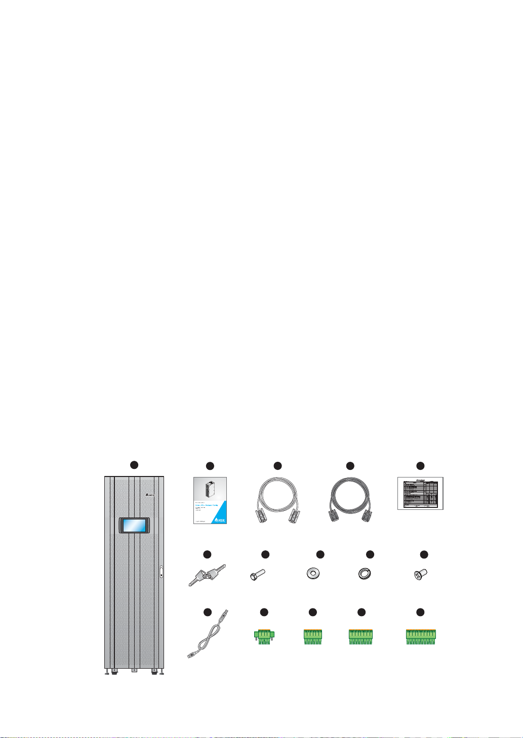
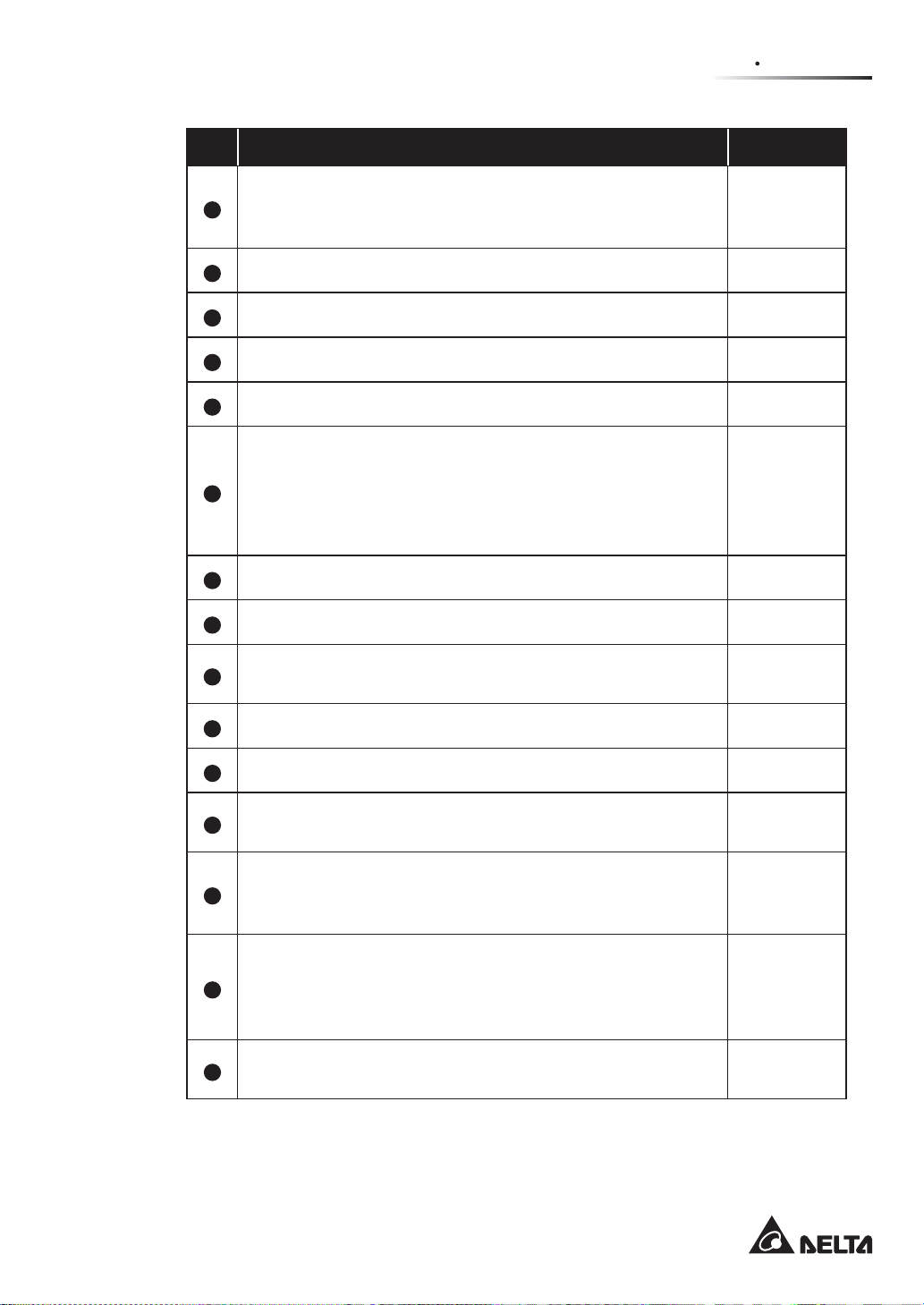
3. The UPS package contains the following items. Please check if any items are missing.
Modulon DPH Series
1
2
6 7 8 9
11
3
×35
12 13 14 15
2-2
4
×35
×2
5
10
×10×35
×2
Page 15
ௐ
ௐ
2
Introduction
No. Item Q’ty
UPS
(two pieces of 50ppi dust filters have been installed on the inner
1
side of the UPS front door before shipment)
User Manual 1 PC
2
RS-232 Cable (1.8 meters) 1 PC
3
Parallel Cable (3 meters) 1 PC
4
Test Report 1 PC
5
Key
6
1 PC
1 PC
(two copies
placed inside
the UPS
cabinet)
M12 Screw (used for input/ output/ battery/ grounding wiring) 35 PCS
7
Washer (used for input/ output/ battery/ grounding wiring) 35 PCS
8
Washer Spring (used for input/ output/ battery/ grounding
9
wiring)
M4 Screw (used to fix the parallel fasteners) 10 PCS
10
USB Cable 1 PC
11
4-Pin Dry Contact Terminal Block
12
(used for REPO dry contacts; please refer to Figure 4-3)
6-Pin Dry Contact Terminal Block
(used for MODBUS and BMS ports located at the rear of the
13
touch panel; please refer to Figure 4-15)
8-Pin Dry Contact Terminal Block
(used for (1) external battery temperature dry contacts and (2)
14
external switch/ breaker status dry contacts; please refer to
Figure 4-3)
10-Pin Dry Contact Terminal Block (used for input and output
15
dry contacts; please refer to Figure 4-3)
35 PCS
1 PC
1 PC
2 PCS
2 PCS
4. If there is any damage or anything missing, please immediately contact the dealer
from whom you purchased the unit.
2-3
Page 16

5. If the UPS needs to be returned, carefully repack the UPS and all of the accessories
using the original packing material that came with the unit.
2.3 Functions & Features
y Hot swappable STS module, communication interfaces and power modules (optional)
realize on-line maintenance, reduce the MTTR (Mean Time to Repair) and expand
system capacity flexibly (200 ~ 500kVA).
y Input power factor > 0.99 and input THDi < 3% save on installation cost and diminish
power contamination.
y Output power factor= 1 (for 500kVA, output power factor is 0.9).
y Efficiency > 96% saves on operation cost.
y Automatic input frequency detection enables operation at 50Hz or 60Hz.
y Automatic restart:
1. The UPS will restart in normal mode automatically right after the AC line resumes
following a low battery shutdown.
2. The UPS returns automatically to normal mode from bypass mode after an overload
condition is cleared.
y Automatically detects whether bypass voltage is out of rating voltage (default: voltage
±15% & frequency ±3Hz). If yes, the UPS will stop supplying power to the critical loads to
protect your electronic equipment.
y Supports ECO mode: when input voltage and frequency are within the range of rating
voltage ±10% and rating frequency ±3Hz, the UPS will transfer to bypass mode; otherwise,
the UPS will transfer to normal mode to reach higher efficiency.
y Both auxiliary power and control circuit adopt redundancy design, which doubly enhances
UPS reliability.
y Suitable for top and bottom wiring by use of the Delta external maintenance bypass
cabinet (optional).
y Generator compatible
y Surge protection and EMI filter functions.
y Remote emergency power off.
y Single input and dual input functions.
y Supports external switch/ breaker status detection.
Modulon DPH Series
2-4
Page 17

ௐ
ௐ
2
Introduction
y Wide AC input voltage range (140Vac~276Vac) reduces frequent transfer from normal
mode to battery mode to save battery consumption and prolong battery life.
y AC start-up function even when the UPS is not connected to the batteries.
WARNING:
Please note that when the UPS is not connected to the batteries, it will not
protect your equipment if the utility power is lost.
y Connects at maximum four external battery cabinets to extend backup time.
y Schedulable battery test and battery replacement alarm.
y Battery temperature monitoring and compensation.
y Battery monitoring system allows measurement of per battery cell’s voltage and current.
y Smart battery charger design allows auto-charging or manual charging to shorten
charging time.
y Provides communication interfaces and a smart slot (where you can install the optional
Relay I/O card for dry contact expansion). Please refer to 4. Communication Interfaces.
y Built-in RS-232 port and USB port located on the communication interfaces allow
monitoring and management of the UPS. For relevant location and information, please
refer to Figure 4-3 and Page 4-11.
y Built-in SNMP card and MODBUS card located at the rear of the touch panel provide
network communication and MODBUS communication respectively. For relevant location
and information, please refer to Page 4-12 and Page 4-13.
y Built-in SNMP card located at the rear of the touch panel allows remote monitoring,
management and event log download of the UPS. For relevant location and information,
please refer to Page 4-12 and Page 4-13.
y Built-in USB ports ( ) located at the rear of the touch panel allow upgrade of the UPS,
touch panel, power modules, system control card and parallel communication cards’
firmware and event log download. For relevant location and information, please refer to
Page 4-12 and Page 4-13.
y Built-in SRAM records at maximum 10000 event logs.
y 10-inch graphic and color touch panel enables the user to easily operate the UPS and
understand the UPS status.
y Fan speed auto adjustment prolongs fan life and reduces noise when the critical loads
decrease. Moreover, fan failure detection circuit is established.
y State-of-the-art microprocessor technology performs self-detection and monitors fan
speed in real time, which provides complete and detailed operating status of the UPS.
2-5
Page 18
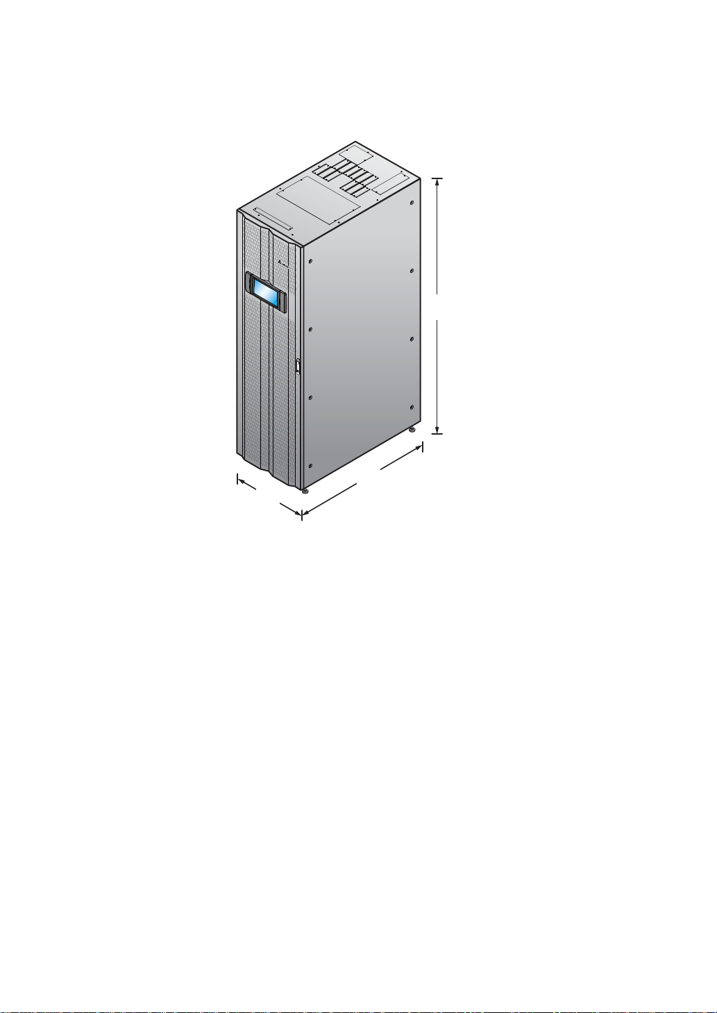
2.4 Exterior and Dimensions
600
mm
2000
mm
1100
mm
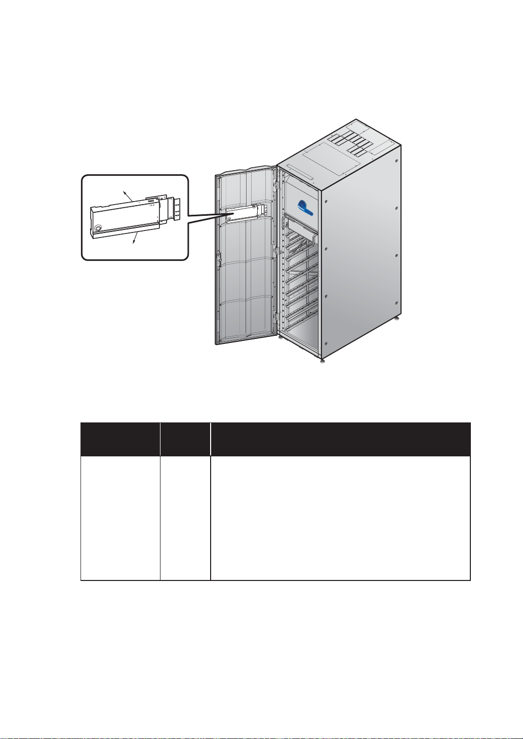
2.5 Front View
On the front of the UPS, there are a 10” color touch panel, a tri-color LED indictor, a door
switch, six casters and four leveling feet. Please see Figure 2-2.
1. For information about the 10” color touch panel, please refer to 7. LCD Display &
Settings.
2. For information about the tri-color LED indicator, please refer to 2.8 Tri-color LED
Indicator & Buzzers.
3. The casters at the bottom of the UPS can be used to move over short distances, and
the leveling feet fix and stabilize the UPS on the ground. Please refer to 5.3 UPS
Transportation for relevant information.
4. Please refer to Figure 2-3 for how to open the UPS front door.
(Figure 2-1: Exterior & Dimensions)
Modulon DPH Series
2-6
Page 19
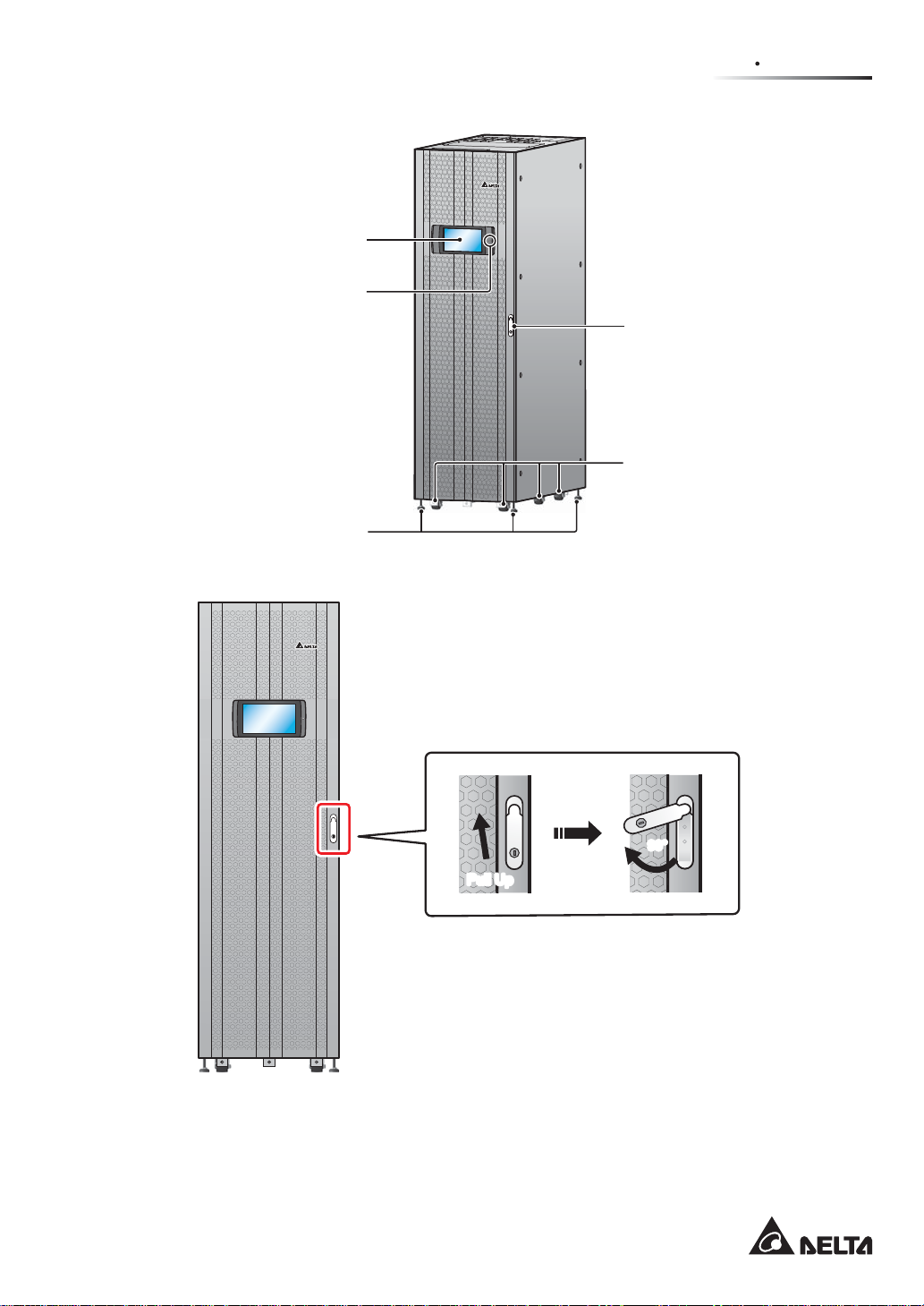
10” Color Touch Panel
Tri-color LED Indictor
Levelling Feet
(Figure 2-2: UPS Front View)
Door Switch
Casters
ௐ
ௐ
2
Introduction
Pull Up
(Figure 2-3: How to Open the UPS Front Door)
2-7
90°90°
Page 20
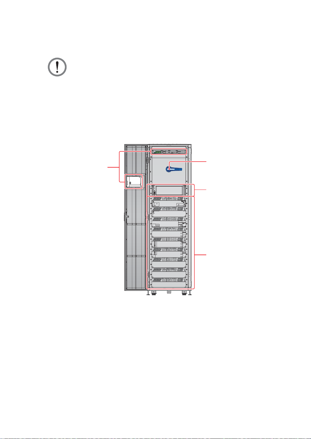
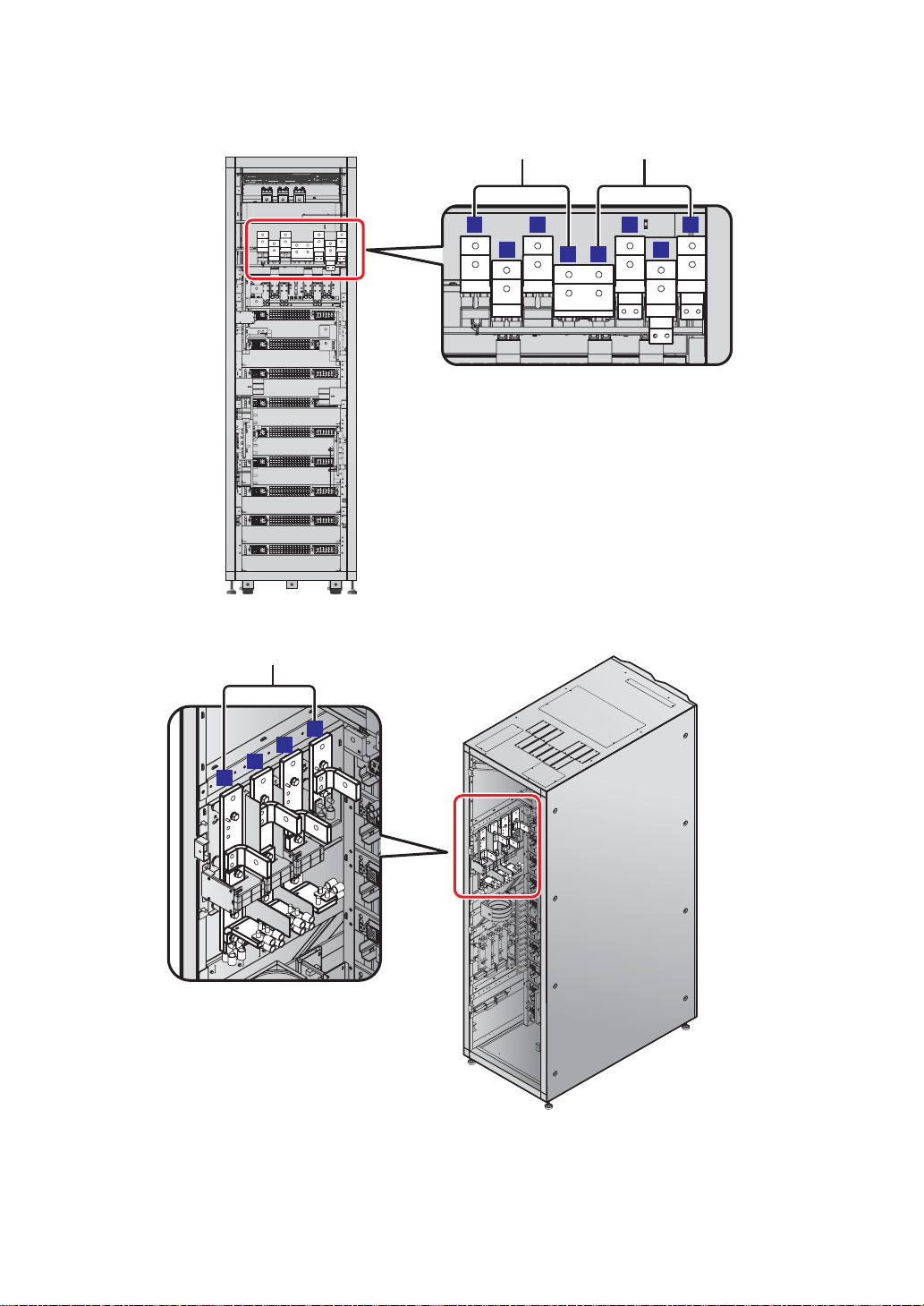
2.6 Internal View
WARNING:
Only authorized Delta engineers or service personnel can perform installation,
wiring, panel & cover removal, maintenance and operation. If you want to execute
any action mentioned above by yourself, the action must be under the supervision
of authorized Delta engineers or service personnel.
After you open the UPS’s front door, you will see the internal mechanisms including
communication interfaces, a bypass switch (Q0), an STS module, and nine power module
slots. Please refer to Figure 2-4.
Communication Interfaces
Internal View
(Front View with Door Open)
DISPLAY
I/P DRY
O/P DRY
EXT.SWITCH
EXT. BATT
CONTACT
CONTACT
STATUS
TEMP.
P1P2
S1S2
P1P2 P3
BT1BT2
REPO
NCNO
BT4
BT3
P4
P5P6
S3S4
P3
P4
N
G
D
A
G
N
D
B
A
B
RESET
M
OD
B
US
BM
S
Y
A
L
ISP
D
LE
O
EMS
ONS
C
I
PARALLEL
PARALLEL
BYPASS SWITCH
O OFF
BATT.
START
BATT.
START
USB RS-232
ON I
Bypass Switch (Q0)
STS Module
1. For information about the communication interfaces, please refer to 4. Communication
Interfaces.
2. For how to turn on/ off the bypass switch (Q0), please refer to Figure 2-5.
Modulon DPH Series
Power Module Slots
(Figure 2-4: UPS Internal View (Front View with Door Open))
2-8
Page 21
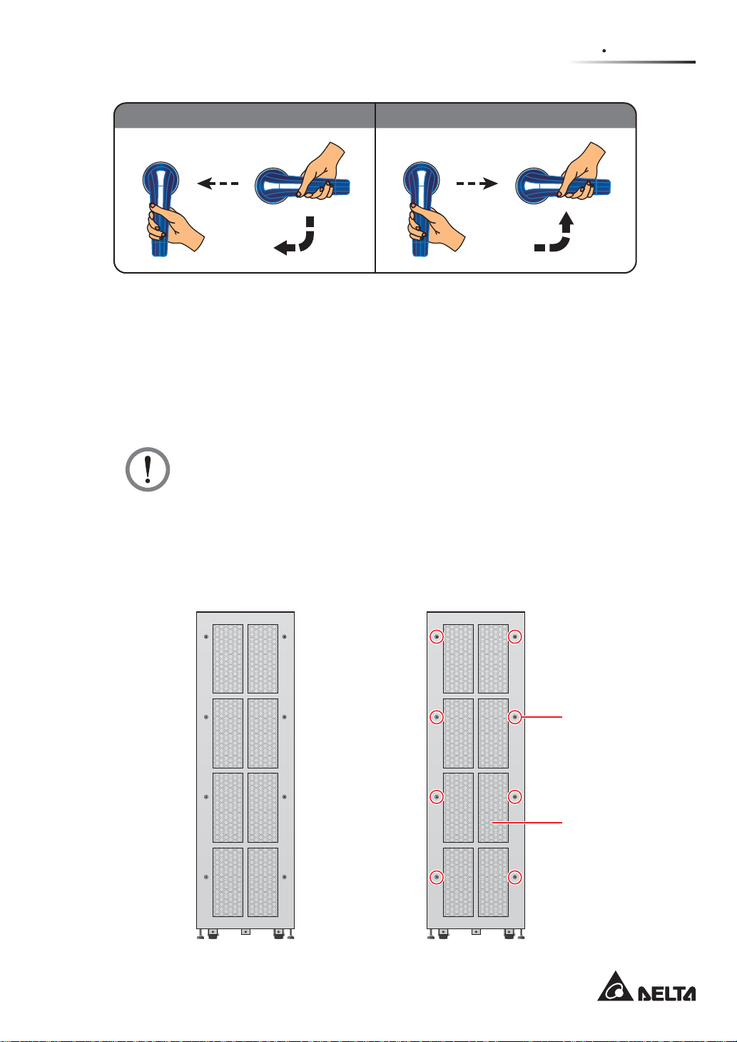
Turn on the Bypass Switch (Q0) Turn off the Bypass Switch (Q0)
ௐ
ௐ
2
Introduction
(ON) (OFF)
ON I
O OFF
3. For STS module information, please refer to 5.7 STS Module.
4. For the power module slots, please follow on-site requirements to install appropriate
number of power modules (optional) into the slots. Please refer to 5.8 Power Module
(Optional) for relevant information.
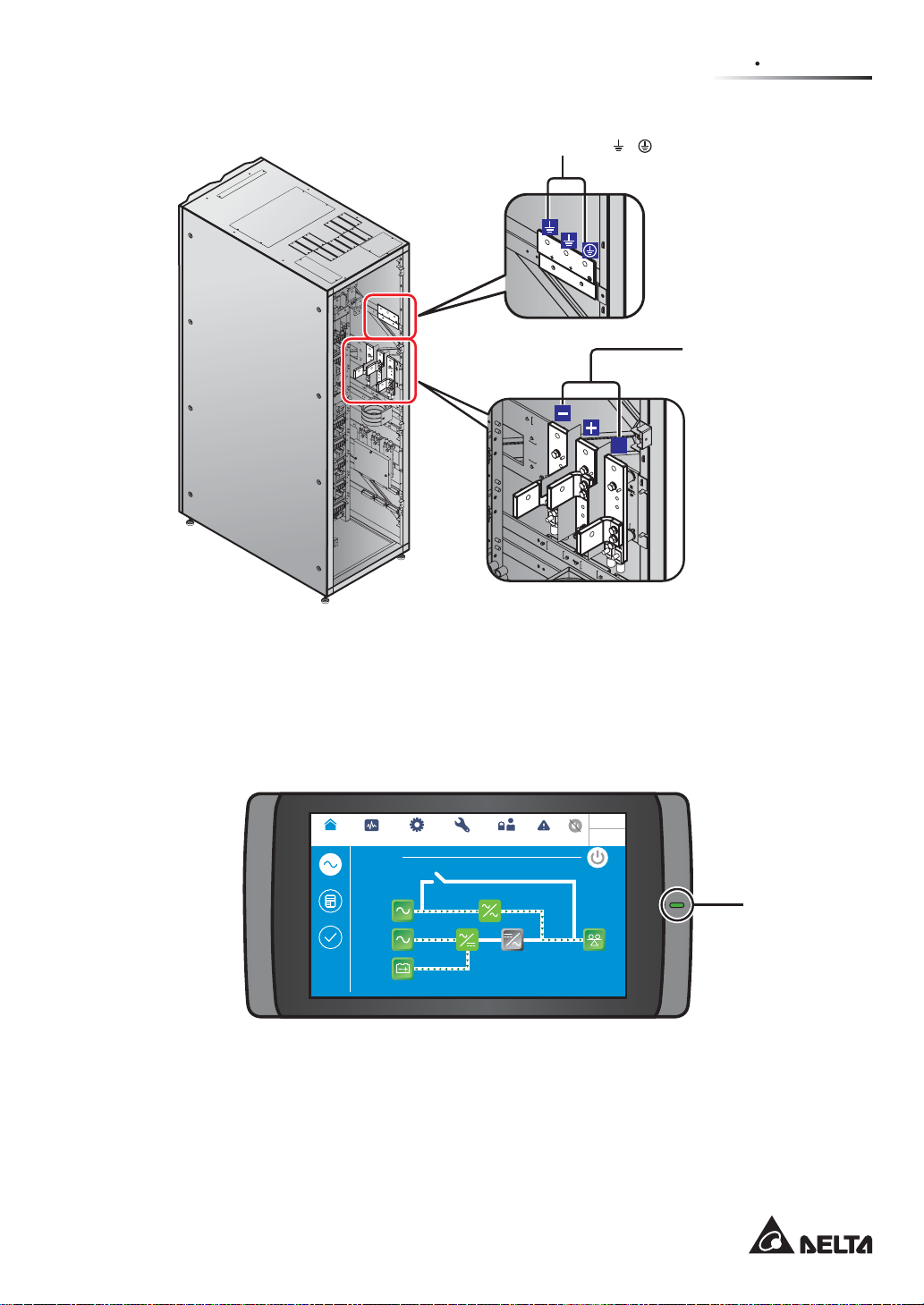
2.7 Rear View
WARNING:
Only authorized Delta engineers or service personnel can perform installation,
wiring, panel & cover removal, maintenance and operation. If you want to execute
any action mentioned above by yourself, the action must be under the supervision
of authorized Delta engineers or service personnel.
The rear view of the UPS is shown in Figure 2-6. Please remove the rear panel (there are
eight screws (see Figure 2-7) to see the wiring terminals shown in Figure 2-8 ~ Figure 2-10.
(ON) (OFF)
ON I
O OFF
ON I
O OFF
90°
(Figure 2-5: Turn On/ Off the Bypass Switch (Q0))
ON I
O OFF
90°
(Rear) (Rear)
M5 Screw X 8
Rear Panel
(Figure 2-6: UPS Rear View) (Figure 2-7: UPS Rear Panel and Screw Location)
2-9
Page 22
32
32
32
32
32
32
35
T
S
R
N
N
BYPASS I/P
BYPASS I/P BYPASS I/P MAIN I/P
T
MAIN I/P
R
MAIN I/P
(Rear View after Rear Panel Removal)
42
42
42
41
Bypass Input T erminals AC Input Terminals
32
32
323232
32
35
BYPASS I/P BYPASS I/P BYPASS I/P MAIN I/PTMAIN I/PRMAIN I/P
BYPASS I/P
TSRNN
22 22 2221 21 21
(Figure 2-8: Wiring Terminals_ AC Input & Bypass Input)
UPS Output Terminals
N
T
S
R
T T
BYPASS I/P
R R
S S
N N
(Rear View after Rear Panel Removal)
Modulon DPH Series
41
42
42
42
(Figure 2-9: Wiring Terminals_ UPS Output)
2-10
Page 23
ௐ
ௐ
2
Introduction
(Rear View after Rear Panel Removal)
(Figure 2-10: Wiring Terminals_ Battery Input & Grounding)
Grounding Terminals
( & )
Battery Input
Terminals
N
2.8 Tri-color LED Indicator & Buzzers
Please see Figure 2-11 for the location of the tri-color LED indictor. For information about the
tri-color LED indicator, please refer to Table 2-1. For information about the 10” color touch
panel, please refer to 7. LCD Display and Settings.
MEASUREMENT
UPS-1.1 SETUP MAINTENANCE
Power Flow
POWER FLOW
Maintenance
Power Flow
Bypass
Bypass
Summary
Mains
System Status
90 %
5 mins
(Figure 2-11: Tri-color LED Indictor Location)
LOG IN
EVENT LOG
User
Load
30 %
10:15
May 25,2018
Bypass
Tri-color
LED Indicator
2-11
Page 24
Open the UPS front door and find the buzzers at the rear of the UPS front door. Please see
Figure 2-12.
(UPS Front View with Door Open)
Buzzer
BYPASS SWITCH
A
B
D
N
G
A
B
D
N
G
T
SE
E
BMS
R
US
MODB
DISPLAY
EMS
ICONSOLE
A
B
D
N
G
A
B
D
N
G
S
BM
S
DBU
O
M
ET
RES
DISPLAY
EMS
ICONSOLE
ON I
Buzzer
(Figure 2-12: Buzzers Location)
Please refer to the table below for the status of the tri-color LED indicator and buzzers.
Table 2-1: Tri-color LED Indicator & Buzzers
Tri-color LED
Indicator
Status Meaning
1. The UPS is running in online mode and the text ‘OnLine’ appears in the upper right corner of the screen.
2. The UPS is running in ECO mode and the text ‘ECO’
appears in the upper right corner of the screen.
Green ON
3. The UPS is running in frequency conversion mode and
the text ‘Frequency Conversion’ appears in the upper
right corner of the screen.
4. The UPS is running in green mode and the text ‘Green’
appears in the upper right corner of the screen.
Modulon DPH Series
2-12
Page 25
ௐ
ௐ
2
Introduction
Tri-color LED
Indicator
Yellow ON
Status Meaning
1. The UPS is running in bypass mode and the text
‘Bypass’ appears in the upper right corner of the
screen.
2. The UPS is running in battery mode and the text
‘Battery’ appears in the upper right corner of the screen.
3. The UPS is running in standby mode and the text
‘Standby’ appears in the upper right corner of the
screen.
4. The UPS is in the soft start status and the text ‘Softstart’
appears in the upper right corner of the screen.
5. The UPS is in the energy recycle status and the text
‘Energy Recycle’ appears in the upper right corner of
the screen.
6. There is a minor or medium warning and the buzzers
sound.
Warning Level Buzzer Frequency
Minor
Medium
The buzzers beep 0.5 second for
every three seconds.
The buzzers beep 0.5 second for
every second.
Red ON
To clear the warning, please refer to 10. Troubleshooting.
There is a major warning and the buzzers sound.
Warning Level Buzzer Frequency
Major Long beep
To clear the warning, please refer to 10. Troubleshooting.
2-13
Page 26

Modulon DPH Series
2-14
Page 27

ௐ
ௐ
3
Operation Modes
3
Operation Modes
3.1 Single Input
3.2 Dual Input
3.3 Hot Standby Redundancy
(Only For Dual Input & At
Least Two UPSs)
3.4 Common Battery (Only
For At Least Two Parallel
UPSs)
3-1
Page 28
The UPS runs in eight basic operation modes, which are online mode, battery mode, bypass mode,
manual bypass mode, ECO mode, frequency conversion mode, green mode and energy recycle
mode. Besides these eight operation modes, the UPS is also designed for common battery application
and hot standby redundancy. Please see the following sections for relevant information.
127(
1. The UPS must be connected with a Delta or non-Delta external maintenance bypass
cabinet. The Delta external maintenance bypass cabinet is optional, and the non-Delta
external maintenance bypass cabinet is user-supplied and should be handled and
configured by Delta service personnel. For the Delta or non-Delta external maintenance
bypass cabinet’s information, please refer to the table below.
There are two models for selection. Please refer to the table below.
Delta External Maintenance Bypass Cabinet (Optional)
Model 3915101965-S 3915101964-S
Delta External
Maintenance
Bypass Cabinet
(Optional)
Non-Delta
External
Maintenance
Bypass Cabinet
(User-supplied,
handled and
configured by
Delta service
personnel)
3 Switches (Input
Switch Q’ty
Wiring Type Top & Bottom Wiring Top & Bottom Wiring
NOTE:)RU PRUH LQIRUPDWLRQ DERXW WKH 'HOWD H[WHUQDO
maintenance bypass cabinet (optional), please refer to its
user manual.
For configurations of the non-Delta external maintenance bypass
cabinet, please refer to the following.
a. Selection of three or four breakers (switches):
(1) Three breakers (switches):
An input breaker (switch), a manual bypass breaker (switch)
and an output breaker (switch) should be installed.
(2) Four breakers (switches):
An input breaker (switch), a bypass breaker (switch), a manual
bypass breaker (switch) and an output breaker (switch) should
be installed.
c. Each breaker (switch) mentioned above must be a 3-pole (R/ S/
T) device and meets the specifications defined in Table 5-3.
d. It is suggested that each breaker (switch) should be configured
with an auxiliary contactor. For relevant information, please refer
to 4.1.4 External Switch/ Breaker Status Dry Contacts.
e. Install the non-Delta external maintenance bypass cabinet next
to the UPS or align it with the UPS for convenient operation.
Switch/ Manual Bypass
Switch/ Output Switch)
4 Switches (Input
Switch/ Bypass Switch/
Manual Bypass Switch/
Output Switch)
Modulon DPH Series
3-2
Page 29
ௐ
ௐ
3
Operation Modes
127(If there are switches but not breakers installed in the external
maintenance bypass cabinet, please install (1) an additional protective device
between the input power and the external maintenance bypass cabinet and (2)
an additional protective device between the connected critical loads and the
external maintenance bypass cabinet. The protective device could be a breaker
or a fuse. For the protective device’s rating current, please refer to the table
below.
200kVA 300kVA 400kVA 500kVA
400A 600A 800A 1000A
2. In this user manual, the meaning of Q0, Q1, Q2, Q3, Q4 and Q5 represents the following.
Code Meaning
Q0 UPS’s Bypass Switch
Q1
Q2
Q3
Q4
Delta or non-Delta External Maintenance Bypass Cabinet’s Input Breaker
or Switch
Delta or non-Delta External Maintenance Bypass Cabinet’s Bypass Breaker
or Switch
Delta or non-Delta External Maintenance Bypass Cabinet’s Manual Bypass
Breaker or Switch
Delta or non-Delta External Maintenance Bypass Cabinet’s Output Breaker
or Switch
Q5 External Battery Cabinet’s Breaker
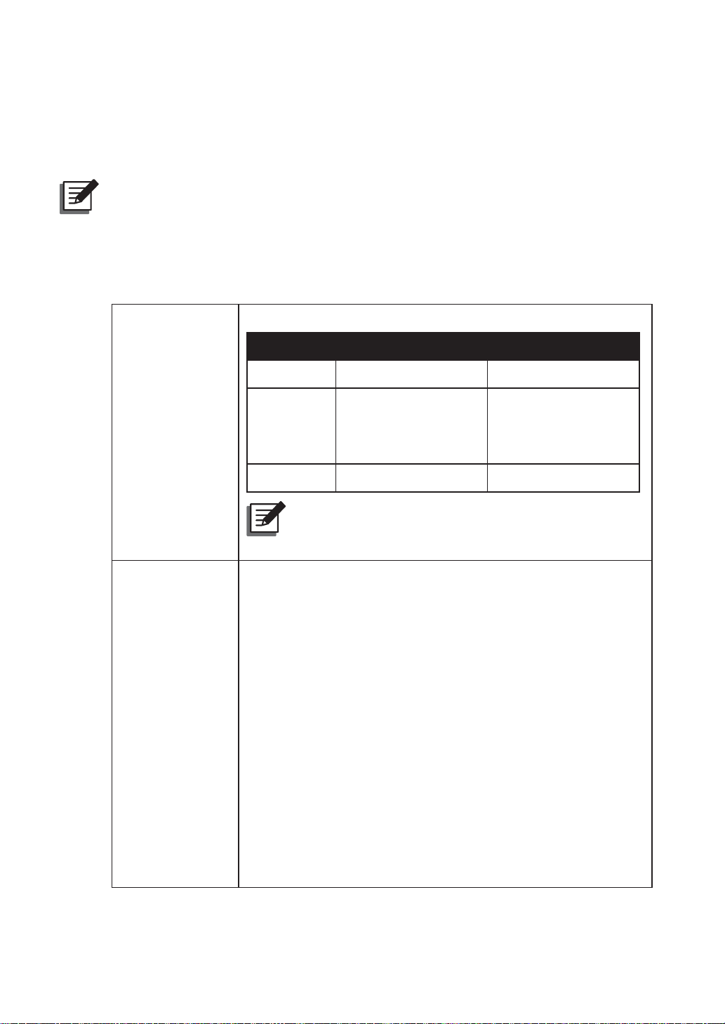
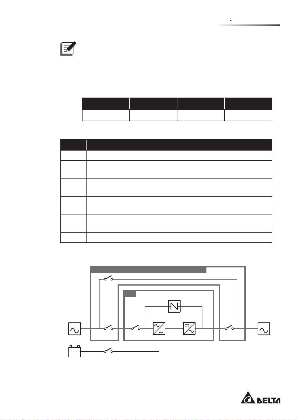
3. The structure of the UPS and the Delta or non-Delta external maintenance bypass cabinet
is shown in Figure 3-1 (single input application) and Figure 3-2 (dual input application).
Delta or non-Delta External Maintenance Bypass Cabinet
Q3
UPS
MAIN LOAD
Q1 Q0 Q4
Static Switch
Rectifier Inverter
Batteries
(Figure 3-1: Single Input Application_ UPS and Delta or non-Delta
Q5
External Maintenance Bypass Cabinet Structure)
3-3
Page 30
Delta or non-Delta External Maintenance Bypass Cabinet
Q3
UPS
BYPA.
Q0Q2
MAIN LOAD
Q1 Q4
Q5
Batteries
(Figure 3-2: Dual Input Application_ UPS and Delta or non-Delta
External Maintenance Bypass Cabinet Structure)
Static Switch
Rectifier Inverter
4. Up to eight UPS units can be paralleled for redundancy and capacity expansion. Only
UPSs with the same capacity, voltage and frequency can be paralleled. Please only use
the provided parallel cable to parallel the UPS units. Otherwise, parallel functions will fail.
3.1 Single Input
3.1.1 Online Mode_ Single Input_ Single Unit
In online mode, the main AC source supplies AC power via the Delta or non-Delta external
maintenance bypass cabinet’s Input Breaker or Switch (Q1) and the UPS’s Bypass Switch
(Q0) to the rectifier, and the rectifier converts the AC power to DC power and supplies the DC
power to the inverter. In the meantime, the rectifier provides charging power to the batteries.
After receiving the DC power, the inverter converts it into clean and stable AC power to the
connected critical loads via the Delta or non-Delta external maintenance bypass cabinet’s
Output Breaker or Switch (Q4). Please refer to Figure 3-3. During online mode, the UPS’s
tri-color LED illuminates green and the text ‘On-Line’ appears in the upper right corner of
the screen.
Modulon DPH Series
3-4
Page 31

Delta or non-Delta External Maintenance Bypass Cabinet
Q3
ௐ
ௐ
3
Operation Modes
UPS
MAIN LOAD
Q1 Q0 Q4
Q5
Batteries
Static Switch
Rectifier Inverter
(Figure 3-3: Online Mode Diagram_ Single Input Single Unit)
3.1.2 Battery Mode_ Single Input_ Single Unit
The UPS transfers to battery mode automatically if the main AC source cannot supply power,
for example, when unstable voltage or a power outage occurs. In battery mode, the batteries
provide DC power and the UPS converts it into AC power and supplies it to the connected
critical loads via the Delta or non-Delta external maintenance bypass cabinet’s Output
Breaker or Switch (Q4). During the conversion process, output voltage remains the same.
Please see Figure 3-4. During battery mode, the UPS’s tri-color LED illuminates yellow and
the text ‘Battery’ appears in the upper right corner of the screen.
Delta or non-Delta External Maintenance Bypass Cabinet
Q3
UPS
MAIN LOAD
Q1 Q0 Q4
Q5
Batteries
Static Switch
Rectifier Inverter
(Figure 3-4: Battery Mode Diagram_ Single Input Single Unit)
3-5
Page 32

3.1.3 Bypass Mode_ Single Input_ Single Unit
When the inverter encounters abnormal situations such as over temperature, overload, short
circuit, abnormal output voltage or low battery, it will automatically shut itself down. If the
UPS detects the bypass AC source is normal, it will automatically switch to bypass mode to
protect the connected critical loads from power interruption. Please refer to Figure 3-5. After
the above-mentioned abnormalities are eliminated, the UPS will switch back to online mode
from bypass mode. During bypass mode, the UPS’s tri-color LED illuminates yellow and the
text ‘Bypass’ appears in the upper right corner of the screen.
Delta or non-Delta External Maintenance Bypass Cabinet
Q3
UPS
MAIN LOAD
Q1 Q0 Q4
Q5
Batteries
(Figure 3-5: Bypass Mode Diagram_ Single Input Single Unit)
Static Switch
Rectifier Inverter
3.1.4 Manual Bypass Mode_ Single Input_ Single Unit
When the UPS needs maintenance, you can manually switch the UPS to manual bypass
mode. To let the UPS run in manual bypass mode, please follow the procedures below:
Confirm that the bypass AC source and the STS module are normal.
1
Press the LCD's ON/ OFF button ( ) once and the ‘POWER OFF?’ screen will pop
2
up to ask you if you want to power off the inverter. Please select ‘YES’.
Turn on the Delta or non-Delta external maintenance bypass cabinet’s Manual Bypass
3
Breaker or Switch (Q3).
Turn off the UPS’s Bypass Switch (Q0).
4
Turn off the Delta or non-Delta external maintenance bypass cabinet’s Input Breaker or
5
Switch (Q1) and Output Breaker or Switch (Q4).
Turn off each external battery cabinet’s breaker (Q5).
6
Modulon DPH Series
3-6
Page 33

ௐ
ௐ
3
Operation Modes
In manual bypass mode, all power inside the UPS is completely cut off and maintenance
personnel can perform maintenance safely. For manual bypass mode diagram, please see
Figure 3-6. During manual bypass mode, the UPS’s tri-color LED and LCD are both off.
WARNING:
1. In manual bypass mode, make sure that all of the breakers or switches (except
the Delta or non-Delta external maintenance bypass cabinet’s Manual Bypass
Breaker or Switch (Q3)) are in the OFF position before working on the UPS’s
internal circuits. This avoids electric shock.
2. After the power inside the UPS is completely cut off, there is no high voltage in
the UPS but in the Delta or non-Delta external maintenance bypass cabinet. Do
not touch the Delta or non-Delta external maintenance bypass cabinet during
UPS maintenance process to avoid electric shock.
3. During manual bypass mode, the UPS’s input power is completely cut off and the
connected critical loads are not protected.
Delta or non-Delta External Maintenance Bypass Cabinet
Q3
UPS
MAIN LOAD
Q1 Q0 Q4
Q5
Batteries
(Figure 3-6: Manual Bypass Mode Diagram_ Single Input Single Unit)
Static Switch
Rectifier Inverter
3-7
Page 34

3.1.5 ECO Mode_ Single Input_ Single Unit
To activate ECO mode, please refer to 6.2.5 ECO Mode Start-up Procedures, 7.6 Main
Screen and 7.10.2 Mode Setting.
In ECO mode, when bypass AC source’s input voltage and frequency are within the range of
rating voltage ±10% and rating frequency ±3Hz, the UPS works in bypass mode; otherwise,
the UPS runs in online mode. For ECO mode diagram, please see Figure 3-7. During ECO
mode, the UPS’s tri-color LED illuminates green and the text ‘ECO’ appears in the upper right
corner of the screen.
Delta or non-Delta External Maintenance Bypass Cabinet
Q3
UPS
MAIN LOAD
Q1 Q0 Q4
Q5
Batteries
(Figure 3-7: ECO Mode Diagram_ Single Input Single Unit)
Static Switch
Rectifier Inverter
3.1.6 Frequency Conversion Mode_ Single Input_ Single Unit
To activate frequency conversion mode, please refer to 6.2.6 Frequency Conversion Mode
Start-up Procedures, 7.6 Main Screen and 7.10.2 Mode Setting.
After the UPS is manually set in frequency conversion mode, the inverter will automatically
select 50Hz or 60Hz as the fixed output frequency. After the output frequency is determined,
the system will automatically disable the bypass function. Please note that, once the inverter
shuts down, there is no bypass output. For the diagram of frequency conversion mode, please
see Figure 3-8. During frequency conversion mode, the UPS’s tri-color LED illuminates
green and the text ‘Frequency Conversion’ appears in the upper right corner of the screen.
Modulon DPH Series
127(During frequency conversion mode, once the inverter shuts down, there is
no bypass output.
3-8
Page 35

Delta or non-Delta External Maintenance Bypass Cabinet
Q3
ௐ
ௐ
3
Operation Modes
UPS
MAIN LOAD
Q1 Q0 Q4
Q5
Batteries
Static Switch
Rectifier Inverter
(Figure 3-8: Frequency Conversion Mode Diagram_ Single Input Single Unit)
3.1.7 Green Mode _ Single Input_ Single Unit
To activate green mode, please refer to 6.2.7 Green Mode Start-up Procedures, 7.6 Main
Screen and 7.10.2 Mode Setting.
Green mode is the same as online mode, but the difference is that the system will automatically
detect the output status (i.e. total load capacity %) to decide which specific power modules
should be fully powered on or idle in order to achieve higher efficiency of the UPS. For the
green mode diagram, please see Figure 3-9. During green mode, the UPS’s tri-color LED
illuminates green and the text ‘Green’ appears in the upper right corner of the screen.
Delta or non-Delta External Maintenance Bypass Cabinet
Q3
UPS
MAIN LOAD
Q1 Q0 Q4
Q5
Batteries
Static Switch
Rectifier Inverter
(Figure 3-9: Green Mode Diagram_ Single Input Single Unit)
3-9
Page 36

3.1.8 Energy Recycle Mode _ Single Input_ Single Unit
127(Energy recycle mode is only applicable to single input and single unit
application.
Energy recycle mode is only applicable to UPS self-test only. Without connection of any
critical loads, the UPS can execute current test under full load condition. Before you activate
energy recycle mode, please make sure that the Delta or non-Delta external maintenance
bypass cabinet’s Manual Bypass Breaker or Switch (Q3), Output Breaker or Switch (Q4) and
each external battery cabinet’s battery breaker (Q5) are in the OFF status.
To activate energy recycle mode (only qualified service personnel can do so), please refer
to 6.2.8 Energy Recycle Mode Start-up Procedures, 7.6 Main Screen and 7.10.2 Mode
Setting.
For the diagram of energy recycle mode, please see Figure 3-10. During energy recycle
mode, the UPS’s tri-color LED illuminates yellow and the text ‘Energy Recycle’ appears in
the upper right corner of the screen.
Delta or non-Delta External Maintenance Bypass Cabinet
Q3
UPS
MAIN LOAD
Q1 Q0 Q4
Q5
Batteries
(Figure 3-10: Energy Recycle Mode Diagram_ Single Input Single Unit)
Static Switch
Rectifier Inverter
Modulon DPH Series
3-10
Page 37

3.1.9 Online Mode_ Single Input_ Parallel Units
In online mode (parallel), the total loads will be equally shared by the parallel UPSs. If one
of the parallel units fails and its load is less than the total capacity of the remaining parallel
units, the failing UPS’s output will be switched off and its load will be equally shared by
the remaining parallel units. If the failing UPS’s load is larger than the total capacity of the
remaining parallel units, all UPSs’ inverters will turn off and the total loads will be supplied
by bypass power. During online mode, each UPS’s tri-color LED illuminates green and each
UPS’s LCD shows the text ‘On-Line’ in the upper right corner. Please refer to Figure 3-11 for
the path of electrical power through the parallel UPSs in online mode.
ௐ
ௐ
3
Operation Modes
1
MAIN
Batteries
2
Delta or non-Delta External Maintenance Bypass Cabinet
Q3
UPS
Q1 Q0 Q4
Q5
ՕۋஂՕטঢҒݳષߒ
Delta or non-Delta External Maintenance Bypass Cabinet
Q3
UPS
Static Switch
Rectifier Inverter
Static Switch
LOAD
MAIN
Batteries
Rectifier Inverter
Q1 Q0 Q4
Q5
(Figure 3-11: Online Mode Diagram_ Single Input Parallel Units)
3-11
Page 38

3.1.10
Battery Mode _ Single Input_ Parallel Units
If the main AC source cannot supply power, for example, when unstable voltage or a power
outage occurs, all parallel UPSs will automatically transfer from online mode to battery mode.
During the conversion process, output voltage remains the same, and during battery mode,
each UPS’s tri-color LED illuminates yellow and each UPS’s LCD shows the text ‘Battery’ in
the upper right corner. Please refer to Figure 3-12 for the path of electrical power through the
parallel UPSs in battery mode.
1
MAIN
Batteries
2
Delta or non-Delta External Maintenance Bypass Cabinet
Q3
UPS
Q1 Q0 Q4
Q5
Delta or non-Delta External Maintenance Bypass Cabinet
Q3
UPS
Static Switch
Rectifier Inverter
Static Switch
LOAD
MAIN
Batteries
Modulon DPH Series
Rectifier Inverter
Q1 Q0 Q4
Q5
Figure 3-12: Battery Mode Diagram_ Single Input Parallel Units
3-12
Page 39

ௐ
ௐ
3
Operation Modes
3.1.11
Bypass Mode_ Single Input_ Parallel Units
In parallel mode, when all inverters encounter abnormal situations such as overload, short
circuit, abnormal output voltage or low battery, they will automatically shut themselves down.
Meanwhile, if all UPSs detect the bypass AC source is normal, they will automatically switch
to bypass mode to protect the connected critical loads from power interruption. The critical
loads will be equally shared by all parallel units. After the abnormalities mentioned above
are eliminated, the UPSs will switch back to online mode from bypass mode. During bypass
mode, each UPS’s tri-color LED illuminates yellow and each UPS’s LCD shows the text
‘Bypass’ in the upper right corner. Please see Figure 3-13 for the path of electrical power
through the parallel UPSs in bypass mode.
1
MAIN
Delta or non-Delta External Maintenance Bypass Cabinet
Q3
UPS
Q1 Q0 Q4
Static Switch
Rectifier Inverter
Batteries
2
MAIN
Batteries
Q5
Delta or non-Delta External Maintenance Bypass Cabinet
Q3
UPS
Q1 Q0 Q4
Q5
(Figure 3-13: Bypass Mode Diagram_ Single Input Parallel Units)
Static Switch
Rectifier Inverter
LOAD
3-13
Page 40

3.1.12
Manual Bypass Mode_ Single Input_ Parallel Units
In parallel mode, if one of the parallel UPSs needs maintenance, please first confirm that
the bypass AC source and each parallel UPS’s STS module are normal. After confirmation,
please follow the procedures below to manually switch each of the parallel UPSs to manual
bypass mode.
Press each LCD’s ON/ OFF button ( ) once and the ‘POWER OFF?’ screen will pop
1
up to ask you if you want to power off the inverter. Please select ‘YES’.
Turn on each Delta or non-Delta external maintenance bypass cabinet’s Manual Bypass
2
Breaker or Switch (Q3).
Turn off each UPS’s Bypass Switch (Q0).
3
Turn off each Delta or non-Delta external maintenance bypass cabinet’s Input Breaker
4
or Switch (Q1) and Output Breaker or Switch (Q4).
Turn off each external battery cabinet’s breaker (Q5).
5
In manual bypass mode, all power inside the parallel UPSs is completely cut off and
maintenance personnel can perform maintenance safely. The connected critical loads will
be supplied by the manual bypass. During manual bypass mode, all parallel UPSs’ tri-color
LEDs and LCDs are off. Please see Figure 3-14 for the path of electrical power through the
parallel UPSs in manual bypass mode.
WARNING:
1. In manual bypass mode, make sure that all of the breakers or switches (except
each Delta or non-Delta external maintenance bypass cabinet’s Manual Bypass
Breaker or Switch (Q3)) are in the OFF position before working on any of the
parallel UPSs’ internal circuits. This avoids electric shock.
2. After the power inside all parallel UPSs is completely cut off, there is no high
voltage in the parallel UPSs but in every Delta or non-Delta external maintenance
bypass cabinet. Do not touch any Delta or non-Delta external maintenance
bypass cabinet during UPS maintenance process to avoid electric shock.
3. During manual bypass mode, each parallel UPS’s input power is completely cut
off and the connected critical loads are not protected.
127(For parallel UPSs, if you want to turn off one of the parallel UPSs for
maintenance, please make sure the total connected critical loads will not exceed the
remaining parallel units’ total capacity.
Modulon DPH Series
3-14
Page 41

ௐ
ௐ
3
Operation Modes
1
MAIN
Batteries
2
Delta or non-Delta External Maintenance Bypass Cabinet
Q3
UPS
Q1 Q0 Q4
Q5
Delta or non-Delta External Maintenance Bypass Cabinet
Q3
UPS
Static Switch
Rectifier Inverter
Static Switch
LOAD
MAIN
Batteries
Rectifier Inverter
Q1 Q0 Q4
Q5
(Figure 3-14: Manual Bypass Mode Diagram_ Single Input Parallel Units)
3-15
Page 42

3.1.13
ECO Mode_ Single Input_ Parallel Units
To activate ECO mode, please refer to 6.2.5 ECO Mode Start-up Procedures, 7.6 Main
Screen and 7.10.2 Mode Setting.
In ECO mode (parallel), when each UPS’s bypass input voltage and frequency are within the
range of rating voltage ±10% and rating frequency ±3Hz, each UPS works in bypass mode;
otherwise, each UPS runs in online mode. During ECO mode, each UPS’s tri-color LED
illuminates green and each UPS’s LCD shows the text ‘ECO’ in the upper right corner. Please
see Figure 3-15 for the path of electrical power through the parallel UPSs in ECO mode.
1
MAIN
Batteries
2
MAIN
Delta or non-Delta External Maintenance Bypass Cabinet
Q3
UPS
Q1 Q0 Q4
Q5
Delta or non-Delta External Maintenance Bypass Cabinet
Q3
UPS
Q1 Q0 Q4
Static Switch
Rectifier Inverter
Static Switch
Rectifier Inverter
LOAD
Batteries
Modulon DPH Series
Q5
(Figure 3-15: ECO Mode Diagram_ Single Input Parallel Units)
3-16
Page 43

ௐ
ௐ
3
Operation Modes
3.1.14
Frequency Conversion Mode_ Single Input_ Parallel Units
To activate frequency conversion mode, please refer to 6.2.6 Frequency Conversion Mode
Start-up Procedures, 7.6 Main Screen and 7.10.2 Mode Setting.
For parallel application, after each of the parallel UPSs is manually set in frequency conversion
mode, each inverter will automatically select 50Hz or 60Hz as the fixed output frequency.
After the output frequency is determined, each system will automatically disable the bypass
function. Please note that, once each inverter shuts down, there is no bypass output. During
frequency conversion mode, each UPS’s tri-color LED illuminates green and each UPS’s
LCD shows the text ‘Frequency Conversion’ in the upper right corner. Please see Figure
3-16 for the path of electrical power through the parallel UPSs in frequency conversion mode.
127(During frequency conversion mode (parallel), once all of the UPSs’ inverters
shut down, there is no bypass output.
1
MAIN
Delta or non-Delta External Maintenance Bypass Cabinet
Q3
UPS
Q1 Q0 Q4
Static Switch
Rectifier Inverter
Batteries
2
MAIN
Batteries
(Figure 3-16: Frequency Conversion Mode Diagram_ Single Input Parallel Units)
Q5
ՕۋஂՕטঢҒݳષߒ
Delta or non-Delta External Maintenance Bypass Cabinet
Q3
UPS
Q1 Q0 Q4
Q5
Static Switch
Rectifier Inverter
3-17
LOAD
Page 44

3.1.15
Green Mode_ Single Input_ Parallel Units
To activate green mode, please refer to 6.2.7 Green Mode Start-up Procedures, 7.6 Main
Screen and 7.10.2 Mode Setting.
For parallel application, green mode is the same as online mode, but the difference is that
each system will automatically detect its UPS’s output status (i.e. total load capacity %) to
decide which specific power modules should be fully powered on or idle in order to achieve
higher efficiency of the UPS. During green mode, each UPS’s tri-color LED illuminates green
and each UPS’s LCD shows the text ‘Green’ in the upper right corner. Please see Figure
3-17 for the path of electrical power through the parallel UPSs in green mode.
1
MAIN
Batteries
2
Delta or non-Delta External Maintenance Bypass Cabinet
Q3
UPS
Q1 Q0 Q4
Q5
ՕۋஂՕטঢҒݳષߒ
Delta or non-Delta External Maintenance Bypass Cabinet
Q3
UPS
Static Switch
Rectifier Inverter
Static Switch
LOAD
MAIN
Batteries
Modulon DPH Series
Rectifier Inverter
Q1 Q0 Q4
Q5
(Figure 3-17: Green Mode Diagram_ Single Input Parallel Units)
3-18
Page 45

3.2 Dual Input
3.2.1 Online Mode_ Dual Input_ Single Unit
In online mode, the main AC source supplies AC power via the Delta or non-Delta external
maintenance bypass cabinet’s Input Breaker or Switch (Q1) to the rectifier and the rectifier
converts the AC power to DC power and supplies the DC power to the inverter. In the
meantime, the rectifier provides charging power to the batteries. After receiving the DC power,
the inverter converts it into clean and stable AC power to the connected critical loads via the
Delta or non-Delta external maintenance bypass cabinet’s Output Breaker or Switch (Q4).
Please see Figure 3-18 for online mode diagram. During online mode, the UPS’s tri-color
LED illuminates green and the text ‘On-Line’ appears in the upper right corner of the screen.
Delta or non-Delta External Maintenance Bypass Cabinet
Q3
ௐ
ௐ
3
Operation Modes
UPS
BYPA.
Q0Q2
MAIN LOAD
Q1 Q4
Batteries
(Figure 3-18: Online Mode Diagram_ Dual Input Single Unit)
Q5
Static Switch
Rectifier Inverter
3.2.2 Battery Mode_ Dual Input_ Single Unit
The UPS transfers to battery mode automatically if the main AC source cannot supply power,
for example, when unstable voltage or a power outage occurs. In battery mode, the batteries
provide DC power and the UPS converts it into AC power and supplies it to the connected
critical loads via the Delta or non-Delta external maintenance bypass cabinet’s Output
Breaker or Switch (Q4). During the conversion process, output voltage remains the same.
Please see Figure 3-19 for battery mode diagram. During battery mode, the UPS’s tri-color
LED illuminates yellow and the text ‘Battery’ appears in the upper right corner of the screen.
3-19
Page 46

Delta or non-Delta External Maintenance Bypass Cabinet
Q3
UPS
BYPA.
Q0Q2
MAIN LOAD
Q1 Q4
Batteries
Q5
Static Switch
Rectifier Inverter
(Figure 3-19: Battery Mode Diagram_ Dual Input Single Unit)
3.2.3 Bypass Mode_ Dual Input_ Single Unit
When the inverter encounters abnormal situations such as over temperature, overload, short
circuit, abnormal output voltage or low battery, it will automatically shut itself down. If the UPS
detects the bypass AC source is normal, it will automatically switch to bypass mode to protect
the connected critical loads from power interruption. Please refer to Figure 3-20. After the
above-mentioned abnormalities are eliminated, the UPS will switch back to online mode from
bypass mode. During bypass mode, the UPS’s tri-color LED illuminates yellow and the text
‘Bypass’ appears in the upper right corner of the screen.
Batteries
Modulon DPH Series
Delta or non-Delta External Maintenance Bypass Cabinet
Q3
UPS
BYPA.
Q0Q2
MAIN LOAD
Q1 Q4
Q5
Static Switch
Rectifier Inverter
(Figure 3-20: Bypass Mode Diagram_ Dual Input Single Unit)
3-20
Page 47

3.2.4 Manual Bypass Mode_ Dual Input_ Single Unit
When the UPS needs maintenance, you can manually switch the UPS to manual bypass
mode. To let the UPS run in manual bypass mode, please follow the procedures below:
Confirm that the bypass AC source and the STS module are normal.
1
Press the LCD's ON/ OFF button ( ) once and the ‘POWER OFF?’ screen will pop
2
up to ask you if you want to power off the inverter. Please select ‘YES’.
Turn on the Delta or non-Delta external maintenance bypass cabinet’s Manual Bypass
3
Breaker or Switch (Q3).
Turn off the UPS’s Bypass Switch (Q0).
4
Turn off the Delta or non-Delta external maintenance bypass cabinet’s Input Breaker or
5
Switch (Q1), Bypass Breaker or Switch (Q2) and Output Breaker or Switch (Q4).
Turn off each external battery cabinet’s breaker (Q5).
6
In manual bypass mode, all power inside the UPS is completely cut off and maintenance
personnel can perform maintenance safely. For manual bypass mode diagram, please see
Figure 3-21. During manual bypass mode, the UPS’s tri-color LED and LCD are both off.
WARNING:
1. In manual bypass mode, make sure that all of the breakers or switches (except
the Delta or non-Delta external maintenance bypass cabinet’s Manual Bypass
Breaker or Switch (Q3)) are in the OFF position before working on the UPS’s
internal circuits. This avoids electric shock.
2. After the power inside the UPS is completely cut off, there is no high voltage in
the UPS but in the Delta or non-Delta external maintenance bypass cabinet. Do
not touch the Delta or non-Delta external maintenance bypass cabinet during
UPS maintenance process to avoid electric shock.
3. During manual bypass mode, the UPS’s input power is completely cut off and the
connected critical loads are not protected.
ௐ
ௐ
3
Operation Modes
3-21
Page 48

Delta or non-Delta External Maintenance Bypass Cabinet
Q3
UPS
BYPA.
Q0Q2
MAIN LOAD
Q1 Q4
Batteries
Q5
Static Switch
Rectifier Inverter
(Figure 3-21: Manual Bypass Mode Diagram_ Dual Input Single Unit)
3.2.5 ECO Mode_ Dual Input_ Single Unit
To activate ECO mode, please refer to 6.2.5 ECO Mode Start-up Procedures, 7.6 Main
Screen and 7.10.2 Mode Setting.
In ECO mode, when the bypass AC source’s input voltage and frequency are within the
range of rating voltage ±10% and rating frequency ±3Hz, the UPS works in bypass mode;
otherwise, the UPS runs in online mode. For ECO mode diagram, please see Figure 3-22.
During ECO mode, the UPS’s tri-color LED illuminates green and the text ‘ECO’ appears in
the upper right corner of the screen.
Delta or non-Delta External Maintenance Bypass Cabinet
Batteries
Modulon DPH Series
Q3
UPS
BYPA.
Q0Q2
MAIN LOAD
Q1 Q4
Q5
Static Switch
Rectifier Inverter
(Figure 3-22: ECO Mode Diagram_ Dual Input Single Unit)
3-22
Page 49

ௐ
3
3.2.6 Frequency Conversion Mode_ Dual Input_ Single Unit
To activate frequency conversion mode, please refer to 6.2.6 Frequency Conversion Mode
Start-up Procedures, 7.6 Main Screen and 7.10.2 Mode Setting.
After the UPS is manually set in frequency conversion mode, the inverter will automatically
select 50Hz or 60Hz as the fixed output frequency. After the output frequency is determined,
the system will automatically disable the bypass function. Please note that, once the inverter
shuts down, there is no bypass output. For the diagram of frequency conversion mode, please
see Figure 3-23. During frequency conversion mode, the UPS’s tri-color LED illuminates
green and the text ‘Frequency Conversion’ appears in the upper right corner of the screen.
127(During frequency conversion mode, once the inverter shuts down, there is
no bypass output.
Delta or non-Delta External Maintenance Bypass Cabinet
Q3
ௐ
Operation Modes
UPS
BYPA.
Q0Q2
MAIN LOAD
Q1 Q4
Batteries
(Figure 3-23: Frequency Conversion Mode Diagram_ Dual Input Single Unit)
Q5
Static Switch
Rectifier Inverter
3-23
Page 50

3.2.7 Green Mode _ Dual Input_ Single Unit
To activate green mode, please refer to 6.2.7 Green Mode Start-up Procedures, 7.6 Main
Screen and 7.10.2 Mode Setting.
Green mode is the same as online mode, but the difference is that the system will automatically
detect the output status (i.e. total load capacity %) to decide which specific power modules
should be fully powered on or idle in order to achieve higher efficiency of the UPS. For the
green mode diagram, please see Figure 3-24. During green mode, the UPS’s tri-color LED
illuminates green and the text ‘Green’ appears in the upper right corner of the screen.
Delta or non-Delta External Maintenance Bypass Cabinet
Q3
UPS
BYPA.
Q0Q2
MAIN LOAD
Q1 Q4
Batteries
Q5
Static Switch
Rectifier Inverter
(Figure 3-24: Green Mode Diagram_ Dual Input Single Unit)
Modulon DPH Series
3-24
Page 51

3.2.8 Online Mode_ Dual Input_ Parallel Units
In online mode (parallel), the total loads will be equally shared by the parallel UPSs. If one
of the parallel units fails and its load is less than the total capacity of the remaining parallel
units, the failing UPS’s output will be switched off and its load will be equally shared by
the remaining parallel units. If the failing UPS’s load is larger than the total capacity of the
remaining parallel units, all UPSs’ inverters will turn off and the total loads will be supplied
by bypass power. During online mode, each UPS’s tri-color LED illuminates green and each
UPS’s LCD shows the text ‘On-Line’ in the upper right corner. Please refer to Figure 3-25
for the path of electrical power through the parallel UPSs in online mode.
ௐ
ௐ
3
Operation Modes
1
BYPA.
MAIN
Batteries
2
BYPA.
MAIN
Delta or non-Delta External Maintenance Bypass Cabinet
Q3
UPS
Q0Q2
Q1 Q4
Q5
Delta or non-Delta External Maintenance Bypass Cabinet
Q3
UPS
Q0Q2
Q1 Q4
Static Switch
Rectifier Inverter
Static Switch
Rectifier Inverter
LOAD
Batteries
Q5
(Figure 3-25: Online Mode Diagram_ Dual Input Parallel Units)
3-25
Page 52

3.2.9 Battery Mode _ Dual Input_ Parallel Units
If the main AC source cannot supply power, for example, when unstable voltage or a power
outage occurs, all parallel UPSs will automatically transfer from online mode to battery mode.
During the conversion process, output voltage remains the same, and during battery mode,
each UPS’s tri-color LED illuminates yellow and each UPS’s LCD shows the text ‘Battery’ in
the upper right corner. Please refer to Figure 3-26 for the path of electrical power through the
parallel UPSs in battery mode.
1
BYPA.
MAIN
Batteries
2
BYPA.
MAIN
Delta or non-Delta External Maintenance Bypass Cabinet
Q3
UPS
Q0Q2
Q1 Q4
Q5
ՕۋஂՕטঢҒݳષߒ
Delta or non-Delta External Maintenance Bypass Cabinet
Q3
UPS
Q0Q2
Q1 Q4
Static Switch
Rectifier Inverter
Static Switch
Rectifier Inverter
LOAD
Batteries
Modulon DPH Series
Q5
(Figure 3-26: Battery Mode Diagram_ Dual Input Parallel Units)
3-26
Page 53

ௐ
ௐ
3
Operation Modes
3.2.10
Bypass Mode_ Dual Input_ Parallel Units
In parallel mode, when all inverters encounter abnormal situations such as overload, short
circuit, abnormal output voltage or low battery, they will automatically shut themselves down.
Meanwhile, if all UPSs detect the bypass AC source is normal, they will automatically switch
to bypass mode to protect the connected critical loads from power interruption. The critical
loads will be equally shared by all parallel units. After the abnormalities mentioned above
are eliminated, the UPSs will switch back to online mode from bypass mode. During bypass
mode, each UPS’s tri-color LED illuminates yellow and each UPS’s LCD shows the text
‘Bypass’ in the upper right corner. Please see Figure 3-27 for the path of electrical power
through the parallel UPSs in bypass mode.
1
BYPA.
MAIN
Delta or non-Delta External Maintenance Bypass Cabinet
Q3
UPS
Q0Q2
Q1 Q4
Static Switch
Rectifier Inverter
Batteries
2
BYPA.
MAIN
Batteries
Q5
ՕۋஂՕטঢҒݳષߒ
Delta or non-Delta External Maintenance Bypass Cabinet
Q3
UPS
Q0Q2
Q1 Q4
Q5
Static Switch
Rectifier Inverter
(Figure 3-27: Bypass Mode Diagram_ Dual Input Parallel Units)
LOAD
3-27
Page 54

3.2.11
Manual Bypass Mode_ Dual Input_ Parallel Units
In parallel mode, if one of the parallel UPSs needs maintenance, please first confirm that
the bypass AC source and each parallel UPS’s STS module are normal. After confirmation,
please follow the procedures below to manually switch each of the parallel UPSs to manual
bypass mode.
Press each LCD’s ON/ OFF button ( ) once and the ‘POWER OFF?’ screen will pop
1
up to ask you if you want to power off the inverter. Please select ‘YES’.
Turn on each Delta or non-Delta external maintenance bypass cabinet’s Manual Bypass
2
Breaker or Switch (Q3).
Turn off each UPS’s Bypass Switch (Q0).
3
Turn off each Delta or non-Delta external maintenance bypass cabinet’s Input Breaker
4
or Switch (Q1), Bypass Breaker or Switch (Q2) and Output Breaker or Switch (Q4).
Turn off each external battery cabinet’s breaker (Q5).
5
In manual bypass mode, all power inside the parallel UPSs is completely cut off and
maintenance personnel can perform maintenance safely. The connected critical loads will
be supplied by the manual bypass. During manual bypass mode, all parallel UPSs’ tri-color
LEDs and LCDs are off. Please see Figure 3-28 for the path of electrical power through the
parallel UPSs in manual bypass mode.
WARNING:
1. In manual bypass mode, make sure that all of the breakers or switches (except
each Delta or non-Delta external maintenance bypass cabinet’s Manual Bypass
Breaker or Switch (Q3)) are in the OFF position before working on any of the
parallel UPSs’ internal circuits. This avoids electric shock.
2. After the power inside all parallel UPSs is completely cut off, there is no high
voltage in the parallel UPSs but in every Delta or non-Delta external maintenance
bypass cabinet. Do not touch any Delta or non-Delta external maintenance
bypass cabinet during UPS maintenance process to avoid electric shock.
3. During manual bypass mode, each parallel UPS’s input power is completely cut
off and the connected critical loads are not protected.
Modulon DPH Series
127(For parallel UPSs, if you want to turn off one of the parallel UPSs for
maintenance, please make sure the total connected critical loads will not exceed the
remaining parallel units’ total capacity.
3-28
Page 55

ௐ
ௐ
3
Operation Modes
1
BYPA.
MAIN
Batteries
2
BYPA.
MAIN
Delta or non-Delta External Maintenance Bypass Cabinet
Q3
UPS
Q0Q2
Q1 Q4
Q5
ՕۋஂՕטঢҒݳષߒ
Delta or non-Delta External Maintenance Bypass Cabinet
Q3
UPS
Q0Q2
Q1 Q4
Static Switch
Rectifier Inverter
Static Switch
Rectifier Inverter
LOAD
Batteries
Q5
(Figure 3-28: Manual Bypass Mode Diagram_ Dual Input Parallel Units)
3-29
Page 56

3.2.12
ECO Mode_ Dual Input_ Parallel Units
To activate ECO mode, please refer to 6.2.5 ECO Mode Start-up Procedures, 7.6 Main
Screen and 7.10.2 Mode Setting.
In ECO mode (parallel), when each UPS’s bypass input voltage and frequency are within the
range of rating voltage ±10% and rating frequency ±3Hz, each UPS works in bypass mode;
otherwise, each UPS runs in online mode. During ECO mode, each UPS’s tri-color LED
illuminates green and each UPS’s LCD shows the text ‘ECO’ in the upper right corner. Please
see Figure 3-29 for the path of electrical power through the parallel UPSs in ECO mode.
1
BYPA.
MAIN
Batteries
2
BYPA.
MAIN
Delta or non-Delta External Maintenance Bypass Cabinet
Q3
UPS
Q0Q2
Q1 Q4
Q5
Delta or non-Delta External Maintenance Bypass Cabinet
Q3
UPS
Q0Q2
Q1 Q4
Static Switch
Rectifier Inverter
Static Switch
Rectifier Inverter
LOAD
Batteries
Modulon DPH Series
Q5
(Figure 3-29: ECO Mode Diagram_ Dual Input Parallel Units)
3-30
Page 57

ௐ
ௐ
3
Operation Modes
3.2.13
Frequency Conversion Mode_ Single Input_ Parallel Units
To activate frequency conversion mode, please refer to 6.2.6 Frequency Conversion Mode
Start-up Procedures, 7.6 Main Screen and 7.10.2 Mode Setting.
For parallel application, after each of the parallel UPSs is manually set in frequency conversion
mode, each inverter will automatically select 50Hz or 60Hz as the fixed output frequency.
After the output frequency is determined, each system will automatically disable the bypass
function. Please note that, once each inverter shuts down, there is no bypass output. During
frequency conversion mode, each UPS’s tri-color LED illuminates green and each UPS’s
LCD shows the text ‘Frequency Conversion’ in the upper right corner. Please see Figure
3-30 for the path of electrical power through the parallel UPSs in frequency conversion mode.
127(During frequency conversion mode (parallel), once all of the UPSs’ inverters
shut down, there is no bypass output.
1
BYPA.
MAIN
Delta or non-Delta External Maintenance Bypass Cabinet
Q3
UPS
Q0Q2
Q1 Q4
Static Switch
Rectifier Inverter
Batteries
2
BYPA.
MAIN
Batteries
Q5
Delta or non-Delta External Maintenance Bypass Cabinet
Q3
UPS
Q0Q2
Q1 Q4
Q5
Static Switch
Rectifier Inverter
(Figure 3-30: Frequency Conversion Mode Diagram_ Dual Input Parallel Units)
3-31
LOAD
Page 58

3.2.14
Green Mode_ Dual Input_ Parallel Units
To activate green mode, please refer to 6.2.7 Green Mode Start-up Procedures, 7.6 Main
Screen and 7.10.2 Mode Setting.
For parallel application, green mode is the same as online mode, but the difference is that
each system will automatically detect its UPS’s output status (i.e. total load capacity %) to
decide which specific power modules should be fully powered on or idle in order to achieve
higher efficiency of the UPS. During green mode, each UPS’s tri-color LED illuminates green
and each UPS’s LCD shows the text ‘Green’ in the upper right corner. Please see Figure
3-31 for the path of electrical power through the parallel UPSs in green mode.
1
BYPA.
MAIN
Batteries
2
BYPA.
MAIN
Delta or non-Delta External Maintenance Bypass Cabinet
Q3
UPS
Q0Q2
Q1 Q4
Q5
Delta or non-Delta External Maintenance Bypass Cabinet
Q3
UPS
Q0Q2
Q1 Q4
Static Switch
Rectifier Inverter
Static Switch
Rectifier Inverter
LOAD
Batteries
Modulon DPH Series
Q5
(Figure 3-31: Green Mode Diagram_ Dual Input Parallel Units)
3-32
Page 59

ௐ
ௐ
3
Operation Modes
3.3 Hot Standby Redundancy (Only For Dual Input & At Least
Two UPSs)
To provide customers more application choices, the UPS with a dual-input configuration can
have a hot standby redundancy function. If you use two UPSs and wish them to work in hot
standby redundancy mode, please connect the output of UPS1 to the bypass AC source of
UPS 2. Please see Figure 3-23. For more information about the hot standby redundancy
application, please contact service personnel.
In normal condition, it is the UPS 2 inverter that supplies power to the critical loads. Both UPS
1 & UPS 2 tri-color LEDs illuminate green.
When the UPS 2 inverter becomes abnormal, the UPS 2 will automatically transfer to bypass
mode and the UPS 1 inverter will supply power to the critical loads. Under such circumstances,
the UPS 1 tri-color LED illuminates green and the UPS 2 tri-color LED illuminates yellow.
1
BYPA.
MAIN
Batteries
2
BYPA.
MAIN
Delta or non-Delta External Maintenance Bypass Cabinet
Q3
UPS
Q0Q2
Q1 Q4
Q5
Delta or non-Delta External Maintenance Bypass Cabinet
Q3
UPS
Q2 Q0
Q1 Q4
Static Switch
Rectifier Inverter
Static Switch
Rectifier Inverter
LOAD
Batteries
Q5
(Figure 3-32: Hot Standby Redundancy Diagram (only for Dual Input & at Least Two UPSs))
3-33
Page 60

3.4 Common Battery (Only for Parallel UPSs connecting to
the Same External Battery Cabinet(s))
To save on your costs and installation space, the parallel UPSs can share their connected
external battery cabinet(s). For common battery application, please install an isolated switch
between each parallel UPS and its connected external battery cabinet(s). Please see Figure
3-33 for two parallel UPSs sharing one external battery cabinet as an example.
If the parallel UPSs share the external battery cabinet(s), you should use the LCD to set up
relevant parameters such as ‘Battery Type’, ‘Capacity’, ‘Battery Strings’, ‘Float Charge
Voltage’, ‘Equalized Charge Voltage’, ‘Charge Current (Max)’, etc. For more information,
please refer to 7.10.4 Battery & Charging Setting.
127(
For common battery application, please use the LCD to set each UPS’s float charge
voltage (default: 272V) the same, each UPS’s equalized charge voltage (default:
280V) the same, and each UPS’s charge current even.
For example:
A. When (1) two UPSs are paralleled, (2) they share one external battery cabinet,
(3) the battery type is 200AH, (4) there are a total of 4 battery strings, and (5)
the charge current is 80A, please use the LCD to set each UPS’s ‘Battery Type’
the same, ‘Capacity’ as 200AH, ‘Battery Strings’ as 2, and ‘Charge Current
(Max)’ as 40A.
B. When (1) three UPSs are paralleled, (2) they share one external battery cabinet,
(3) the battery type is 300AH, (4) there are a total of 3 battery strings, and (5)
the charge current is 90A, please use the LCD to set each UPS’s ‘Battery Type’
the same, ‘Capacity’ as 300AH, ‘Battery Strings’ as 1, and ‘Charge Current
(Max)’ as 30A.
Modulon DPH Series
3-34
Page 61

ௐ
ௐ
3
Operation Modes
Batteries
1
MAIN
2
MAIN
Delta or non-Delta External Maintenance Bypass Cabinet
Q3
UPS
Q1 Q0 Q4
Q5
Delta or non-Delta External Maintenance Bypass Cabinet
Q3
UPS
Q1 Q0 Q4
Static Switch
Rectifier Inverter
Static Switch
Rectifier Inverter
LOAD
Q5
(Figure 3-33: Common Battery Diagram_ only for Parallel UPSs
Connecting to the Same External Battery Cabinet(s))
3-35
Page 62

Modulon DPH Series
3-36
Page 63

ௐ
ௐ
4
Communication Interfaces
4
Communication
Interfaces
4.1 Communication Interfaces
on the Front of the UPS
with Front Door Open
4.2 Communication Interfaces
at the Rear of the Touch
Panel
4-1
Page 64

The communication interfaces are hot swappable and located at two different places. One is on the
front of the UPS with front door open and the other is at the rear of the touch panel. Please see Figure
4-1.
Internal View
(Front View with Door Open)
4.2 Communication Interfaces
(at the Rear of the Touch Panel)
DISPLAY
O/P DRY
I/P DRY
EXT.SWITCH
EXT. BATT
CONTACT
CONTACT
STATUS
TEMP.
P1P2
S1S2
BT1BT2
P1P2 P3
PARALLEL
REPO
NCNO
BT4
BT3
PARALLEL
P4
P5P6
S3S4
P3
P4
BYPASS SWITCH
O OFF
G
ND
A
G
ND
B
A
B
R
E
SE
T
M
O
DB
US
M
B
S
AY
DISPL
OLE
S
M
E
ICONS
BATT.
START
BATT.
START
USB RS-232
4.1 Communication Interfaces
(on the Front of the UPS with
ON I
Front Door Open)
(Figure 4-1: Communication Interfaces Location)
4.1 Communication Interfaces on the Front of the UPS with
Front Door Open
The following communication interfaces are located on the front of the UPS with front door
open. Please see the description below.
2 3
DISPLAY
NC NO
EXT.SWITCH
EXT. BATT
TEMP.
S1 S2
BT1 BT2
REPO
BT4
BT3
S3 S4
1
(Figure 4-2: Communication Interfaces_ on the Front of the UPS with Front Door Open)
Modulon DPH Series
STATUS
O/P DRY
CONTACT
P1 P2 P3
P4
P5 P6
I/P DRY
CONTACT
P1 P2
P3
PARALLEL
P4
PARALLEL
USB RS-232
4 5
4-2
BATT.
START
BATT.
START
Page 65

ௐ
ௐ
4
Communication Interfaces
No. Item Q’ty Description
Includes a display port, REPO dry contacts,
Dry Contact Card 1 PC
1
external battery temperature dry contacts,
external switch/ breaker status dry contacts,
output dry contacts and input dry contacts.
Display
Port
Contacts
2
3
4
5
External
Battery
Temperature
Dry Contacts
DISPLAY
EXT. BATT
TEMP.
BT1 BT2
REPO
NC NO
BT3
REPO
Dry
Parallel Communication
Card
2 PCS
SMART Slot 1 PC
Each card includes two parallel ports and one
LED indicator.
You can install the optional Relay I/O card for
dry contact expansion.
System Control Card 1 PC Includes a USB port and an RS-232 port.
Auxiliary Power Card 2 PCS
External Switch/
Breaker Status
O/P DRY
EXT.SWITCH
CONTACT
STATUS
S1 S2
P1 P2 P3
BT4
P4
S3 S4
Output
Dry
Contacts
Dry Contacts
I/P DRY
CONTACT
P1 P2
P5 P6
P3
P4
Input
Dry
Contacts
(Figure 4-3: Communication Interfaces Functions)
Backup Parallel
Communication
Card’s LED Indicator
PARALLEL
PARAL LEL
Master
Parallel
Parallel
Ports
Communication
Card’s LED Indicator
Each card includes a LED indicator and a
battery start button.
SMART
USB RS-232
USB
Port
Slot
RS-232
Port
Auxiliary
Power
Card
Auxiliary
Power Card
Auxiliary
Power
Card’s LED
Indicator
BATT.
START
BATT.
START
Auxiliary Power
Card’s LED
Indicator
Battery
Start
Button
4.1.1 Display Port
Before shipment, the display port has been connected to the 10” touch panel with the
designated cable in Delta factory.
4.1.2 REPO Dry Contacts
The REPO dry contacts provide you with quick and convenient interfaces to shut down the
UPS safely when an emergency occurs. Connect the REPO dry contacts to a user-supplied
switch and you can remotely shut down the UPS. The REPO dry contacts provide normally
open (NO) and normally closed (NC) these two options for use.
4-3
Page 66

REPO
NC NO
5V
DISPLAY
NC NO
REPO
Buffer
3
4
NO
5V
Buffer
1
2
NC
UPS
(Figure 4-4: REPO Dry Contacts Design)
127(If you want to enable the normally closed (NC) function, please take out
the dry contact card (see Figure 4-5) and remove its Jump CNR3 (see Figure 4-6)
before you turn on the UPS.
Screw x 2
BATT.
EXT. BATT
TEMP.
BT1 BT2
BT3
BT4
EXT.SWITCH
STATUS
S1 S2
S3 S4
O/P DRY
CONTACT
P1 P2 P3
P4
P5 P6
I/P DRY
CONTACT
P1 P2
P3
PARALLEL
P4
PARAL LEL
USB RS-232
START
BATT.
START
Dry Contact Card
Modulon DPH Series
(Figure 4-5: Dry Contact Card Location)
4-4
Page 67

Jump CNR3
Dry Contact Card
ௐ
ௐ
4
Communication Interfaces
(Figure 4-6: Jump CNR3 Location)
4.1.3 External Battery Temperature Dry Contacts
You can use the external battery temperature dry contacts (BT1, BT2, BT3 and BT4) to detect
at maximum four external battery cabinets’ temperature. You need to purchase the battery
cabinet temperature sensor cable (optional).
EXT. BATT
TEMP.
BT1 BT2
BT4
BT3
(Figure 4-7: External Battery Temperature Dry Contacts Design)
4-5
Page 68

4.1.4 External Switch/ Breaker Status Dry Contacts
There are four sets of external switch/ breaker status dry contacts (S1, S2, S3 and S4), which
can be used to detect the status of input, bypass, manual bypass and output switches or
breakers. Please follow the table below to connect the dry contacts to normally open (NO) or
normally closed (NC) devices.
Type Connection
Dry Contact_ S1 Normally closed (NC) device
Dry Contact_ S2 Normally closed (NC) device
Dry Contact_ S3 Normally closed (NC) device
Dry Contact_ S4 Normally open (NO) device
EXT.SWITCH
STAT US
S1 S2
S4
S3
5V
Buffer
Buffer
Buffer
Buffer
9
11
2mA. Max
5V
13
15
2mA. Max
5V
5V
10
12
14
16
2mA. Max
2mA. Max
S1
S2
S3
S4
UPS
(Figure 4-8: External Switch/ Breaker Status Dry Contacts Design)
Modulon DPH Series
4-6
Page 69

ௐ
ௐ
4
Communication Interfaces
No. Event Description
External input switch or breaker
1
detection.
External bypass switch or
2
breaker detection.
External output switch or
3
breaker detection.
External manual bypass switch
4
or breaker detection.
4.1.5 Output Dry Contacts
There are six sets of programmable output dry contacts (see Figure 4-9). Please use the
touch panel to set each dry contact as normally open (NO) or normally closed (NC). Each dry
contact can be assigned with a specific event. Six out of twenty-one events can be assigned
according to your applications. To learn how to set up, please contact your local dealer and
refer to 7.10.6 Dry Contact Setting. For the twenty-one events, please refer to the table
below.
127(Since the output dry contacts belong to the secondary circuit, the voltage of
each dry contact’s connected device should not exceed 60Vdc/ Vac to avoid electric
shock and insufficient insulation.
Detect the external input switch or breaker’s
status (default: S1).
Detect the external bypass switch or breaker’s
status (default: S2).
Detect the external output switch or breaker’s
status (default: S3).
Detect the external manual bypass switch or
breaker’s status (default: S4).
4-7
Page 70

O/P DRY
CONTACT
P1 P2 P3
P4
P5 P6
P6 (Max. 0.5A/12V)
P5 (Max. 0.5A/12V)
P4 (Max. 0.5A/12V)
P3 (Max. 0.5A/12V)
P2 (Max. 0.5A/12V)
P1 (Max. 0.5A/12V)
112
10
6
8
2
4
9
11
5
7
1
3
UPS
DRY F_NO
COMM_F
DRY E_NO
COMM_E
DRY D_NO
COMM_D
DRY C_NO
COMM_C
DRY B_NO
COMM_B
DRY A_NO
COMM_A
1
4
2
3
1
4
2
3
1
4
2
3
1
4
2
3
1
4
2
3
1
4
2
3
+12VS
DRY 6
+12VS
DRY 5
+12VS
DRY 4
+12VS
DRY 3
+12VS
DRY 2
+12VS
DRY 1
Modulon DPH Series
(Figure 4-9: Output Dry Contacts Design)
4-8
Page 71

ௐ
ௐ
4
Communication Interfaces
No. Event Description
1 None No set-up.
2 Load On Inverter The UPS works in online mode.
3 Load On Bypass The UPS works in bypass mode.
4 Load On Battery
5 Battery Low
6 Bypass Input Abnormal
7 Battery Test Fail
8 Internal Comm. Fail
When the main AC source fails, the batteries supply
power to the critical loads.
When the UPS runs in battery mode, battery voltage
is lower than the setup limit (default: 220Vdc).
The bypass voltage, frequency or phase sequence
is abnormal.
During the battery test, the battery voltage is out of
the setup limit.
The #n power module’s internal communication is
abnormal.
9 External Parallel Comm. Fail In parallel mode, parallel communication is abnormal.
10 Output Overload
11 EPO Activated
12 Load On Manual Bypass
13 Battery Over Temperature
The UPS is overloaded or the UPS shuts down to let
the bypass supply power to the critical loads.
The EPO button is pressed to urgently power off the
UPS.
The Manual Bypass Breaker or Switch (Q3) is turned
on and the UPS transfers to manual bypass mode.
The external battery cabinet’s temperature is too
high.
14 Output Voltage Abnormal The output voltage is too high or too low.
15 Battery Need Replacement The battery replacement date is due.
16 Bypass Over Temperature The bypass static switch temperature is too high.
17 Bypass Static Switch Fault The bypass static switch has an open/ short issue.
18 UPS Over Temperature The UPS temperature is too high.
When the EPO button is pressed or low battery
19 Battery Breaker Shunt Trip
shutdown occurs, the UPS will send a signal to the
connected external shunt trip device to cut off the
battery power.
When the UPS’s bypass SCR has an open/ short
20 Backfeed Protection
issue, the UPS will send a signal to the connected
external shunt trip device to cut off the backfeed
voltage.
21 General Alarm
When any UPS alarm occurs, the UPS will send an
I/O signal.
4-9
Page 72

4.1.6 Input Dry Contacts
There are four sets of programmable input dry contacts (see Figure 4-10). Please use the
touch panel to set each dry contact as normally open (NO) or normally closed (NC). The
input dry contacts allow the UPS to receive external signals from peripheral devices and let
the UPS response accordingly. Each input dry contact can be assigned with a specific event.
There are four events can be assigned according to your applications. To learn how to set
up, please contact your local dealer and refer to 7.10.6 Dry Contact Setting. For information
about the four events, please refer to the table below.
I/P DRY
CONTACT
P1 P2
P3
P4
Dry-1
Dry-2
Dry-3
Dry-4
5V
Buffer
5V
Buffer
5V
Buffer
5V
Buffer
13
15
2mA. Max
17
19
2mA. Max
14
16
2mA. Max
18
20
2mA. Max
UPS
(Figure 4-10: Input Dry Contacts Design)
P1
P2
P3
P4
Modulon DPH Series
4-10
Page 73

ௐ
ௐ
4
Communication Interfaces
No. Event Description
1 None No set-up.
2 Generator Status Generator status detection.
3 Battery Ground Fail Battery leakage detection.
External Battery Breaker
4
Detection
Status detection of the external battery cabinet’s
breaker or switch.
4.1.7 Parallel Communication Cards
The UPS has two parallel communication cards, which are master parallel communication
card and backup parallel communication card. Each card has one LED indicator. Please see
Figure 4-11 for their location.
If both cards work normally, the master parallel communication card’s LED indicator will
illuminate green and the backup parallel communication card’s LED indicator will illuminate
yellow.
If one card works normally and the other works abnormally, the normal card’s LED indicator
will illuminate green and the abnormal card’s LED indicator will illuminate red.
During initialization process, both cards’ LED indicators flash yellow.
Backup Parallel Communication Card’s
LED Indicator
DISPLAY
NC NO
EXT.SWITCH
EXT. BATT
STATUS
TEMP.
S1 S2
BT1 BT2
REPO
BT4
BT3
S3 S4
O/P DRY
CONTACT
P1 P2 P3
P4
P5 P6
I/P DRY
CONTACT
P1 P2
P3
P4
Backup Parallel
Communication Card
PARAL LEL
PARALLEL
USB RS-232
BATT.
START
BATT.
START
Master Parallel Communication Card’s
(Figure 4-11: Location of Parallel Communication Cards and Their LED Indicators)
4.1.8 Parallel Ports
The parallel ports are used to connect parallel UPSs to increase the system capacity and
redundancy. With the provided parallel cable, up to eight UPS units with the same capacity,
voltage and frequency can be paralleled. To enhance parallel reliability, please adopt Daisy
Chain method (see Figure 5-41 & Figure 5-43) to execute parallel configuration.
WARNING:
The provided parallel cable is placed in the accessory package. Using other types
of cables to connect the parallel UPSs may cause parallel failure, malfunctions and
accidents.
LED Indicator
Master Parallel
Communication Card
4-11
Page 74

4.1.9 SMART Slot
You can install the optional Relay I/O card (for dry contact expansion) into the SMART slot
shown in Figure 4-12. For relevant installation and application information, please contact
Delta customer service.
SMART Slot
4.1.10
4.1.11
DISPLAY
REPO
NC NO
EXT. BATT
TEMP.
BT1 BT2
BT3
BT4
EXT.SWITCH
STATUS
S1 S2
S3 S4
O/P DRY
CONTACT
P1 P2 P3
P4
P5 P6
I/P DRY
CONTACT
P1 P2
P3
PARALLEL
P4
PARAL LEL
USB RS-232
BATT.
START
BATT.
START
(Figure 4-12: SMART Slot Location)
USB Port & RS-232 Port
You can use the provided RS-232 cable or the USB cable to connect the UPS’s RS-232 port
or USB port with a computer, and use either the USB port or the RS-232 port to upgrade the
firmware of UPS, power modules, system control card and parallel communication cards and
download event logs.
127(Do not use the RS-232 port and the USB port at the same time.
Auxiliary Power Cards
The UPS has two auxiliary power cards. Each card has one LED indicator. Please see Figure
4-13 for their location.
If the auxiliary power card works normally, its LED indicator will illuminate green. If the
auxiliary power card is off or abnormal, its LED indicator will be off.
DISPLAY
NC NO
EXT.SWITCH
EXT. BATT
STATUS
TEMP.
S1 S2
BT1 BT2
REPO
BT4
BT3
S3 S4
Modulon DPH Series
Auxiliary
Auxiliary Power Card’s
Power Card
I/P DRY
O/P DRY
CONTACT
CONTACT
P1 P2
P1 P2 P3
P4
P5 P6
P3
P4
PARALLEL
PARALLEL
USB RS-232
Auxiliary
Auxiliary Power Card’s
Power Card
(Figure 4-13: Location of Auxiliary Power Cards and their LED Indicators)
4-12
LED Indicator
BATT.
START
BATT.
START
LED Indicator
Page 75

ௐ
MODBUS
BMS
GND
B
A
GND
B
A
DISPLAY
EMS
ICONSOLE
RESET
ௐ
4
Communication Interfaces
4.1.12
Battery Start Buttons
Please refer to 6.2.2 Battery Mode Start-up Procedures for relevant information.
Battery Start Button
DISPLAY
NC NO
EXT. BATT
STATUS
TEMP.
S1 S2
BT1 BT2
REPO
BT4
BT3
S3 S4
CONTACT
P1 P2 P3
P4
P5 P6
CONTACT
P1 P2
P3
PARAL LEL
P4
PARALLEL
USB RS-232
I/P DRY
O/P DRY
EXT.SWITCH
Battery Start Button
BATT.
START
BATT.
START
(Figure 4-14: Location of Battery Start Buttons)
4.2 Communication Interfaces at the Rear of the Touch Panel
The following communication interfaces are located at the rear of the touch panel. Please see
the description below.
(Front View with Door Open)
1 2
3
BYPASS SWITCH
A
B
D
N
G
A
B
D
N
G
MS
B
DBUS
MO
SET
RE
DISPLAY
EMS
ICONSOLE
6 7
5
4
ON I
(Figure 4-15: Communication Interfaces_ at the Rear of the Touch Panel)
4-13
Page 76

No. Item Description
1
2
(Built-in MODUBS card)
3
4
5
6
RESET Press the RESET button once to restart the LCD.
MODBUS
BMS
DISPLAY
EMS/ CONSOLE
(USB Ports)
7
(Built-in SNMP card)
1. Lets the UPS have MODBUS communication
function.
2. Connects to a user-supplied monitoring system.
Connects to a user-supplied battery management
system or Delta battery management system
(optional).
1. Connects to the display port shown in Figure 4-3.
2. Before shipment, the display port has been
connected to the 10” touch panel with the
designated cable in Delta factory.
Connects to a user-supplied environmental monitoring
system or Delta EnviroProbe 1000/ 1100/ 1200
(optional).
There are two USB ports. Connect a user-supplied
USB flash drive to any of the USB ports to (1) upgrade
the UPS and LCD’s firmware and (2) download event
logs.
1. Lets the UPS have network communication function.
2. Connects to a user-supplied monitoring system.
Modulon DPH Series
4-14
Page 77

ௐ
ௐ
5
Installation and Wiring
5
Installation and
Wiring
5.1 Before Installation and
Wiring
5.2 Installation Environment
5.3 UPS Transportation
5.4 Fixing the UPS
5.5 Wiring
5.6 External Battery Cabinet
Connection Warnings
5.7 STS Module
5.8 Power Module (Optional)
5-1
Page 78

5.1 Before Installation and Wiring
1. Please read this user manual thoroughly before installation, wiring and usage. Only
authorized Delta engineers or service personnel can perform installation, wiring, panel &
cover removal, maintenance and operation. If you want to execute any action mentioned
above by yourself, the action must be under the supervision of authorized Delta engineers
or service personnel. If you use a forklift or other equipment to move the UPS, please
make sure its load bearing is sufficient. Please refer to Table 5-1.
2. The UPS must be connected with an external battery cabinet (user-supplied, handled and
configured by Delta service personnel). Please refer to 5.6 External Battery Cabinet
Connection Warnings for relevant information.
3. The UPS must be connected with a Delta or non-Delta external maintenance bypass
cabinet. The Delta external maintenance bypass cabinet is optional, and the non-Delta
external maintenance bypass cabinet is user-supplied and should be handled and
configured by Delta service personnel. For the Delta or non-Delta external maintenance
bypass cabinet’s information, please refer to the table below.
There are two models for selection. Please refer to the table below.
Delta External Maintenance Bypass Cabinet (Optional)
Model 3915101965-S 3915101964-S
Delta External
Maintenance
Bypass
Cabinet
(Optional)
Switch Q’ty
Wiring Type Top & Bottom Wiring Top & Bottom Wiring
3 Switches (Input Switch/
Manual Bypass Switch/
Output Switch)
4 Switches (Input Switch/
Bypass Switch/ Manual
Bypass Switch/ Output
Switch)
Non-Delta
External
Maintenance
Bypass
Cabinet
(User-supplied,
handled and
configured by
Delta service
personnel)
Modulon DPH Series
NOTE:)RU PRUH LQIRUPDWLRQ DERXW WKH 'HOWD H[WHUQDO
maintenance bypass cabinet (optional), please refer to its
user manual.
For configurations of the non-Delta external maintenance bypass
cabinet, please refer to the following.
a. Selection of three or four breakers (switches):
(1) Three breakers (switches):
An input breaker (switch), a manual bypass breaker (switch) and
an output breaker (switch) should be installed.
(2) Four breakers (switches):
An input breaker (switch), a bypass breaker (switch), a manual
bypass breaker (switch) and an output breaker (switch) should
be installed.
b. Each breaker (switch) mentioned above must be a 3-pole (R/ S/ T)
device and meets the specifications defined in Table 5-3.
c. It is suggested that each breaker (switch) should be configured with
an auxiliary contactor. For relevant information, please refer to 4.1.4
External Switch/ Breaker Status Dry Contacts.
d. Install the non-Delta external maintenance bypass cabinet next to
the UPS or align it with the UPS for convenient operation.
5-2
Page 79

ௐ
ௐ
5
Installation and Wiring
127(If there are switches but not breakers installed in the external
maintenance bypass cabinet, please install (1) an additional protective device
between the input power and the external maintenance bypass cabinet and (2)
an additional protective device between the connected critical loads and the
external maintenance bypass cabinet. The protective device could be a breaker
or a fuse. For the protective device’s rating current, please refer to the table
below.
200kVA 300kVA 400kVA 500kVA
400A 600A 800A 1000A
4. In this user manual, the meaning of Q0, Q1, Q2, Q3, Q4 and Q5 represents the following.
Code Meaning
Q0 UPS’s Bypass Switch
Q1
Q2
Q3
Q4
Q5 External Battery Cabinet’s Breaker
Delta or non-Delta External Maintenance Bypass Cabinet’s Input Breaker
or Switch
Delta or non-Delta External Maintenance Bypass Cabinet’s Bypass Breaker
or Switch
Delta or non-Delta External Maintenance Bypass Cabinet’s Manual Bypass
Breaker or Switch
Delta or non-Delta External Maintenance Bypass Cabinet’s Output Breaker
or Switch
5.2 Installation Environment
y Install the UPS indoors. Do not place it outdoors.
y Make sure that transportation routes (e.g. corridors, door gates, elevators, etc.) and
installation area can accommodate and bear the weight of the UPS, external battery
cabinet, Delta or non-Delta external maintenance bypass cabinet (refer to 5.1 Before
Installation and Wiring for relevant information) and handling equipment. Please refer
to Table 5-1 for floor weight loading information.
Table 5-1: UPS Floor Weight Loading Table
DPH Series UPS_ 200~500kVA
UPS Weight: 317 kg (without power modules)
UPS Weight Loading: 480.3 kg/m
UPS Capacity
Power Module Q’ty 4 6 8 9
Weight 461 kg 533 kg 605 kg 641 kg
Weight Loading 698.5 kg/m
200kVA/
200kW
2
5-3
2
(without power modules)
300kVA/
300kW
807.6 kg/m
2
400kVA/
400kW
916.7 kg/m
2
500kVA/
450kW
971.2 kg/m
2
Page 80

y The UPS adopts top wiring. Please leave adequate space on the top of the UPS to allow
cable entry. If you use the Delta external maintenance bypass cabinet (optional), top
wiring and bottom wiring are both applicable.
y Ensure that the installation area is big enough for maintenance and ventilation. Since
the UPS adopts the design of air inlet at the front and air outlet at the rear and external
battery cabinets must be placed next to the UPS, we suggest that you:
1. Keep a distance of 100cm from the front of the UPS for maintenance and ventilation.
2. Keep a distance of at least 35cm from the back of the UPS for ventilation, or at least
50cm for maintenance.
3. Keep a distance of 50cm from the top of the UPS for maintenance, wiring and
ventilation.
Air Outlet
Air Inlet
(Figure 5-1: UPS Air Inlet & Outlet Direction)
y Keep the installation area clean. Please note that wiring routes must be hermetic to
prevent possible damage from rodents.
y Keep the installation area’s temperature around 25°C and humidity below 95%. The
highest operating altitude is 1000 meters above sea level.
y For safety concerns, we suggest that you:
1. Equip surroundings of the installation area with CO
2. Install the UPS in an environment where fireproof materials are used to construct the
walls, floors and ceilings.
3. Install the UPS on a floor that is made of noncombustible materials.
or dry powder fire extinguishers.
2
Modulon DPH Series
5-4
Page 81

y Do not allow unauthorized personnel to enter the installation area and assign specified
personnel to keep the UPS key.
WARNING:
Do not use air conditioners or similar equipment to blow into the rear of the UPS and
hinder ventilation.
5.3 UPS Transportation
y At the bottom of the UPS, there are six casters to help you to move the UPS to a designated
area. Before you move the UPS, please turn the four leveling feet counterclockwise to
raise them off the ground. This protects the leveling feet from damage when moving the
UPS. Please use sufficient manpower (at least six people) and equipment (e.g. forklift) to
carefully move the UPS from its pallet to ground. Please pay attention to the movement
of the casters to avoid accidents.
ௐ
ௐ
5
Installation and Wiring
Caster
(Figure 5-2: UPS Leveling Foot and Caster)
WARNING:
1. The UPS is fixed on the pallet with two balance supports. When taking apart the
two balance supports from the UPS, please pay attention to the movement of the
casters to avoid accidents.
2. Please refer to the Unpacking Guide attached to the UPS external wooden box
for location of the balance supports.
Leveling Foot
y The casters are designed to move on level ground. Do not move the UPS on an uneven
surface. This might cause damage to the casters or tip the UPS which could damage the
unit.
y After the UPS has been removed from the pallet to ground, we suggest that at least
three people move the UPS to the installation area. One person use their hands to hold a
lateral side of the UPS, one person hold the other lateral side of the UPS with their hands,
and one person use their hands to push the UPS either from the front side or from the
backside to move the unit to the installation area and avoid tipping the UPS.
y If you need to move the UPS over a long distance, please use appropriate equipment like
a forklift. Do not use the UPS casters to move the unit over a long distance.
5-5
Page 82

5.4 Fixing the UPS
Please follow the steps below:
Before fixing the UPS in a designated installation area, please double check whether
1
the area’s floor weight loading is sufficient to bear the UPS, external battery cabinet,
Delta or non-Delta external maintenance bypass cabinet and handling equipment (i.e.
forklift) to avoid accidents. For UPS floor weight loading information, please refer to
Table 5-1.
After the UPS is moved to the designated installation area, use a #17 wrench to stabilize
2
the UPS four leveling feet on the floor. Please note that the UPS must stand on the floor
stably and levelly without any tipping.
Use a 17mm socket wrench and three M10 screws 1 (originally used to fix the front
3
balance support on the pallet) to install the front balance support (removed during
the unpacking process) at the front of the UPS. Use the three expansion screws
(provided by qualified service personnel) to fix the front balance support on the ground
to avoid UPS movement. Please see Figure 5-3.
(Front View)
2
Expansion Screw
& Nut X 3
2
Use a 17mm socket wrench and three M10 screws 1 (originally used to fix the rear
4
balance support on the pallet) to install the rear balance support (removed during the
unpacking process) at the rear of the UPS. Use the three expansion screws
by qualified service personnel) to fix the rear balance support on the ground to avoid
UPS movement. Please see Figure 5-4.
Modulon DPH Series
1
M10 Screw
X 3
(Figure 5-3: Install the Balance Support at the Front of UPS)
5-6
Balance
Support
Ground
(provided
2
Page 83

ௐ
ௐ
5
Installation and Wiring
(Rear View)
2
Expansion Screw
& Nut X 3
Balance
Support
1
M10 Screw
X 3
Ground
(Figure 5-4: Install the Balance Support at the Rear of UPS)
WARNING:
If you don’t use the balance supports to fix the UPS on the ground, the unit might
topple over. For safety concerns, please use the balance supports to fix the UPS to
the floor.
Follow 5.5 Wiring to perform wiring procedures.
5
Follow 5.6 External Battery Cabinet Connection Warnings to connect the external
6
battery cabinet(s).
Follow 5.8 Power Module (Optional) to install the power modules.
7
After finishing the procedures above, close the UPS front door.
8
5-7
Page 84

5.5 Wiring
5.5.1 Pre-wring Warnings
127(
1. Before wiring, please ensure that you have followed 5.4 Fixing the UPS to fix the
UPS in the designated installation area firmly.
2. Before wiring, please read 5.5 Wiring thoroughly.
3. Only authorized Delta engineers or service personnel can perform installation,
wiring, panel & cover removal, maintenance and operation. If you want to
execute any action mentioned above by yourself, the action must be under the
supervision of authorized Delta engineers or service personnel.
4. The UPS must be connected with a Delta or non-Delta external maintenance
bypass cabinet. The Delta external maintenance bypass cabinet is optional,
and the non-Delta external maintenance bypass cabinet is user-supplied and
should be handled and configured by Delta service personnel. For the Delta or
non-Delta external maintenance bypass cabinet’s information, please refer to 1.2
Connection Warnings.
y Before wiring or making any electrical connection, make sure that the power supplied to
the input and output of the UPS is completely cut off.
y The UPS adopts top wiring. Please leave adequate space on the top of the UPS to allow
cable entry. If you use the Delta external maintenance bypass cabinet (optional), top
wiring and bottom wiring are both applicable.
y Check that the size, diameter, phase, polarity are correct for each cable that needs
connecting to the UPS, external battery cabinet and external maintenance bypass
cabinet. Please refer to Table 5-2 for the specifications of input/ output/ battery cables,
switches and breakers.
Table 5-2: Specifications of Input/ Output/ Battery Cables, Switches and Breakers
Input
Modulon DPH Series
127(Table 5-2 is based on (1) default input/ output voltage: 220V, (2) default
battery Q’ty: 40PCS and (3) default charge current per power module: 5A. For
other conditions different from Table 5-2, please contact service personnel for
relevant values.
DPH 200~500kVA
Capacity
Power Module Q’ty 4689
Rated current at input
voltage 220V (in
the status of battery
charging)
200kVA/
200kW
340A 510A 680A 765A
5-8
300kVA/
300kW
400kVA/
400kW
500kVA/
450kW
Page 85

DPH 200~500kVA
200kVA/
200kW
95mm
2 PCS
300mm
3 PCS
Input
Capacity
Recommended cable
size (R/ S/ T/ N)
Maximum cable size
(R/ S/ T/ N)
Cable lug width 50mm 50mm 50mm 50mm
Screw size M12 M12 M12 M12
Output
Rated current at output
voltage 220V
Recommended cable
size (R/ S/ T/ N)
Maximum cable size
(R/ S/ T/ N)
303A 455A 606A 758A
95mm
2 PCS
300mm
3 PCS
Cable lug width 50mm 50mm 50mm 50mm
Screw size M12 M12 M12 M12
Battery
Rated current (12V x 40
PCS batteries)
Recommended cable
size (+/ -/ N)
Maximum cable size
(+/ -/ N)
440A 660A 880A 990A
120mm
2 PCS
240mm
4 PCS
Cable lug width 50mm 50mm 50mm 50mm
Screw size M12 M12 M12 M12
Tightening Torque M12=500±20Kgf.cm
UPS’s Bypass Switch (Q0) 1000A
Delta or non-Delta External
Maintenance Bypass Cabinet’s
400A 600A 800A 1000A
Input Breaker or Switch (Q1)
Delta or non-Delta External
Maintenance Bypass Cabinet’s
400A 600A 800A 1000A
Bypass Breaker or Switch (Q2)
Delta or non-Delta External
Maintenance Bypass Cabinet’s
Manual Bypass Breaker or
400A 600A 800A 1000A
Switch (Q3)
Delta or non-Delta External
Maintenance Bypass Cabinet’s
400A 600A 800A 1000A
Output Breaker or Switch (Q4)
External Battery Cabinet’s
Breaker (Q5)
500A 800A 1000A 1200A
2
x
2
x
2
x
2
x
2
x
2
x
300kVA/
300kW
150mm2 x
2 PCS
300mm2 x
3 PCS
150mm2 x
2 PCS
300mm2 x
3 PCS
240mm2 x
2 PCS
240mm2 x
4 PCS
ௐ
ௐ
5
Installation and Wiring
400kVA/
400kW
240mm2 x
2 PCS
300mm2
3 PCS
240mm2 x
2 PCS
300mm2 x
3 PCS
185mm2 x
3 PCS
240mm2 x
4 PCS
500kVA/
450kW
185mm2 x
3 PCS
300mm2 x
3 PCS
185mm2 x
3 PCS
300mm2 x
3 PCS
240mm2 x
3 PCS
240mm2 x
4 PCS
5-9
Page 86

127(
1. In accordance with National Electrical Codes (NEC), please install a suitable
conduit and bushing for cable protection.
2. Please refer to national and local electrical codes for acceptable non-fuse
switches, breakers and cable size.
3. The cables mentioned in Table 5-2 with PVC material and with temperature
resistance up to 105°C are suggested.
4. The tightening torque for M12 screw should be 500±20Kgf.cm.
y To avoid UPS failure, the input of the UPS must be a Y connection.
y If there is a floating voltage between the input power’s neutral (N) and the ground ( ), and
you require that the VNG of the UPS should be zero, we suggest that you install an isolation
transformer in front of the input side of the UPS, and connect the isolation transformer’s
secondary neutral (N) and the ground (
) to the nearest place of the transformer.
y The main AC source must be a three-phase four-wire system and meets the specifications
specified on the UPS rating label. For main AC source connection, make sure it is in
positive phase sequence. Please refer to 5.5.3 Single Unit Wiring and 5.5.4 Parallel
Units Wiring for wiring information.
y For external battery cabinet connection, please check the battery polarity. Do not connect
the batteries in reverse. Please refer to 5.6 External Battery Cabinet Connection
Warnings.
y &RQQHFWWKHH[WHUQDOEDWWHU\FDELQHW¶VJURXQGLQJWHUPLQDOௗௗ ௗௗWRWKH'HOWDRUQRQ'HOWD
H[WHUQDOPDLQWHQDQFH E\SDVVFDELQHW¶VJURXQGLQJWHUPLQDOௗௗ
5-16 and Figure 5-19 for grounding information.
y 7KH836¶VJURXQGLQJWHUPLQDOௗௗ ௗௗPXVW EH JURXQGHG 3OHDVH XVHULQJW\SHWHUPLQDOV
ZKHQ ZLULQJ )RU WKH ORFDWLRQ RI WKH 836¶V JURXQGLQJ WHUPLQDOௗௗ
Figure 5-14.
WARNING:
1. Wrong wiring will cause damage to the UPS and electric shock.
2. The UPS will not work normally if the main AC source’s neutral (N) is not firmly
connected or not connected to the Delta or non-Delta external maintenance
bypass cabinet’s AC Input neutral (N) terminal.
3. If the UPS is not grounded, the power boards and components might be
damaged after the UPS is powered on.
5.5.2 Single Input/ Dual Input Modification
WARNING:
Only authorized Delta engineers or service personnel can modify single input/ dual
input setup.
The UPS default setting is single input. If you want to modify it into dual input, please follow
the procedures below.
ௗ3OHDVH UHIHUWRFigure
ௗ SOHDVH UHIHU WR
Modulon DPH Series
5-10
Page 87

ௐ
32
32
32
32
32
32
35
BYPASS I/P
T
S
R
N
N
BYPASS I/P
BYPASS I/P BYPASS I/P MAIN I/P
T
MAIN I/P
R
MAIN I/P
ௐ
5
Installation and Wiring
Unscrew the eight M5 screws to remove the rear panel (see Figure 5-5 and Figure
1
5-6). After removing the real panel, you will see the AC Input terminals and Bypass Input
terminals shown in Figure 5-7.
(Rear) (Rear)
M5 Screw X 8
Rear Panel
(Figure 5-5: UPS Rear View) (Figure 5-6: Rear Panel & Screw Location)
(Rear View after Rear Panel Removal)
32
32
323232
32
BYPASS I/P
35
BYPASS I/P BYPASS I/P BYPASS I/P MAIN I/PTMAIN I/PRMAIN I/P
TSRNN
22 22 2221 21 21
Bypass Input Terminals AC Input Terminals
T T
R R
S S
N N
(Figure 5-7: Wiring Terminals_ AC Input & Bypass Input)
5-11
Page 88

Unscrew the six screws and six nuts to remove the nine cables connected between the
2
AC Input Terminals (R/ S/ T) and the Bypass Input terminals (R/ S/ T) in order to modify
the UPS from single input into dual input. Please refer to Figure 5-8.
Rear View after Rear Panel Removal
32
32
323232
32
BYPASS
35
BYPASS I/P BYPASS I/P BYPASS I/P MAIN I/PTMAIN I/PRMAIN I/P
TSRNN
22 22 2221 21 21
(Figure 5-8: Remove the Nine Cables that Connect the AC Input Terminals
(R/ S/ T) and the Bypass Input Terminals (R/ S/ T))
Remove the 3 Cables, 2 Screws
and 2 Nuts that Connect the AC
Input and Bypass Input’s T Terminals
Remove the 3 Cables, 2 Screws
and 2 Nuts that Connect the AC
Input and Bypass Input’s R Terminals
Remove the 3 Cables, 2 Screws
and 2 Nuts that Connect the AC
Input and Bypass Input’s S Terminals
127(
1. Please keep the six screws, six nuts and the nine cables well for future use.
2. If you want to modify the UPS from dual input into single input, please use the
removed six screws and six nuts to reinstall the removed nine cables.
5.5.3 Single Unit Wiring
127(
1. Only authorized Delta engineers or service personnel can perform installation,
wiring, panel & cover removal, maintenance and operation. If you want to
execute any action mentioned above by yourself, the action must be under the
supervision of authorized Delta engineers or service personnel.
2. The UPS rating voltage is 220/ 380Vac, 230/ 400Vac or 240/ 415Vac.
3. The external battery cabinet’s rating voltage is ±240Vdc.
4. Before wiring, please read 5.5 Wiring thoroughly.
Modulon DPH Series
5-12
Page 89

ௐ
ௐ
5
Installation and Wiring
y Single Input (Single Unit)
When there is only one AC power source, single unit wiring procedures are as follows.
The UPS adopts top wiring. Please leave adequate space on the top of the UPS to
1
allow cable entry.
127(If you use the Delta external maintenance bypass cabinet
(optional), top wiring and bottom wiring are both applicable. For relevant
information, please refer to Delta External Maintenance Bypass Cabinet
User Manual.
Remove the eleven covers on the top of the UPS for cable entry. Each top cover
2
has two #6-32 screws. For the location of top covers, please refer to the white areas
shown in Figure 5-9.
(Top of the UPS)
(Figure 5-9: Location of Top Covers)
Unscrew the eight M5 screws to remove the rear panel (see Figure 5-10 and
3
Figure 5-1 1). After removing the real panel, you will see the wiring terminals shown
in Figure 5-12 ~ Figure 5-14.
5-13
Page 90

(Rear) (Rear)
32
32
32
32
32
32
35
BYPASS I/P
T
S
R
N
N
BYPASS I/P
BYPASS I/P BYPASS I/P MAIN I/P
T
MAIN I/P
R
MAIN I/P
M5 Screw X 8
Rear Panel
(Figure 5-10: UPS Rear View) (Figure 5-11: Rear Panel & Screw Location)
(Rear View after Rear Panel Removal)
32
32
323232
32
BYPASS I/P
35
BYPASS I/P BYPASS I/P BYPASS I/P MAIN I/PTMAIN I/PRMAIN I/P
TSRNN
22 22 2221 21 21
(Figure 5-12: Wiring Terminals_ AC Input & Bypass Input)
Bypass Input Terminals AC Input Terminals
T T
R R
S S
N N
Modulon DPH Series
5-14
Page 91

ௐ
42
42
42
41
ௐ
5
Installation and Wiring
UPS Output Terminals
N
T
S
R
(Figure 5-13: Wiring Terminals_ UPS Output)
(Rear View after Rear Panel Removal)
(Rear View after Rear Panel Removal)
1
4
42
2
4
42
Grounding Terminals
( & )
Battery Input
Terminals
N
(Figure 5-14: Wiring Terminals_ Battery Input & Grounding)
5-15
Page 92

For how to perform wiring between the UPS and the Delta or non-Delta external
4
maintenance bypass cabinet, please refer to T able 5-3. For the detailed information
about the Delta or non-Delta external maintenance bypass cabinet, please refer to
5.1 Before Installation and Wiring.
Table 5-3: Wiring between the UPS and the Delta or non-Delta External
Maintenance Bypass Cabinet
No. Item*
AC Input
1
Terminals
Bypass
2
3
4
Input
Terminals
UPS
Output
Terminals
Battery
Input
Terminals
1
Description Function
• Single Input: There is no need to
connect these AC Input Terminals.
Include R/ S/ T/
N terminals.
• Dual Input: The terminals connect
to the Delta or non-Delta external
maintenance bypass cabinet’s input
breaker or switch (Q1).
• Single Input: The terminals connect
to the Delta or non-Delta external
maintenance bypass cabinet’s input
Include R/ S/ T/
N terminals.
breaker or switch (Q1).
• Dual Input: The terminals connect
to the Delta or non-Delta external
maintenance bypass cabinet’s bypass
breaker or switch (Q2).
Include R/ S/ T/
N terminals.
Connect to the Delta or non-Delta
external maintenance bypass cabinet’s
output breaker or switch (Q4).
• If you choose to use the Delta external
maintenance bypass cabinet (optional),
please connect these terminals to
the Delta external maintenance
Include +/ -/ N
terminals.
bypass cabinet’s Battery Input
Terminals.
• If you choose to use the non-Delta
external maintenance bypass cabinet,
please contact service personnel for
battery configurations.
Modulon DPH Series
Includes one
grounding
5
terminal (for the
UPS’s protective
• Connects to the Delta or non-Delta
external maintenance bypass
cabinet’s grounding terminal (
earthing).
127(*
1
The items listed in the above ‘Item’ column are all located at the
rear of the UPS. Please refer to Figure 5-12 ~ Figure 5-14.
5-16
).
Page 93

ௐ
ௐ
5
Installation and Wiring
For how to perform wiring for the Delta or non-Delta external maintenance bypass
5
cabinet, please refer to Table 5-4. For the detailed information about the Delta
or non-Delta external maintenance bypass cabinet, please refer to 5.1 Before
Installation and Wiring.
Table 5-4: Delta or non-Delta External Maintenance Bypass Cabinet Wiring
Information
Input
2
Description Function
Includes
R/ S/ T/ N
terminals*
The breaker or switch (Q1) connects to
the main AC source.
3
.
No. Item*
1
Breaker or
Switch (Q1)
Bypass
2
Breaker or
Switch (Q2)
(Only for
dual input
Includes
R/ S/ T/ N
terminals*
The breaker or switch (Q2) connects to
the bypass AC source.
3
.
application)
3
4
Manual
Bypass
Breaker or
Switch (Q3)
Output
Breaker or
Switch (Q4)
Includes
R/ S/ T/ N
terminals*
Includes
R/ S/ T/ N
terminals*
• Single Input: The breaker or switch (Q3)
connects to the main AC source.
• Dual Input: The breaker or switch (Q3)
3
.
connects to the bypass AC source.
The breaker or switch (Q4) connects to
the critical loads.
3
.
• If you choose to use the Delta external
maintenance bypass cabinet (optional),
please connect these terminals to the
Battery Input
5
Terminals
Include +/ -/
N terminals.
external battery cabinet.
• If you choose to use the non-Delta
external maintenance bypass cabinet,
please contact service personnel for
battery configurations.
Includes one
6
grounding
terminal.
For the Delta or non-Delta external
maintenance bypass cabinet’s protective
earthing.
The three grounding terminals shall
connect to
Includes at
7
least three
grounding
terminals.
1. the UPS’s grounding terminal (
2. the external battery cabinet’s grounding
terminal (
), and
3. the connected critical loads’ grounding
terminal (
).
),
Please refer to Figure 5-16 and Figure
5-19.
5-17
Page 94

127(
1. *2 If you choose to use the non-Delta external maintenance bypass
cabinet (user-supplied), all breakers, switches and terminals listed in
the above ‘Item’ column must be installed. For the configurations of
the non-Delta external maintenance bypass cabinet, please refer to 5.1
Before Installation and Wiring.
3
2. *
If you choose to use the Delta external maintenance bypass cabinet
(optional), please note that each switch only has R/ S/ T terminals.
The N terminals are located on the cabinet’s copper bars. For relevant
information, please refer to Delta External Maintenance Bypass
Cabinet User Manual.
Confirm that the UPS’s Bypass Switch (Q0) is in the OFF position.
6
Confirm that the Delta or non-Delta external maintenance bypass cabinet’s Input
7
Breaker or Switch (Q1), Manual Bypass Breaker or Switch (Q3) and the Output
Breaker or Switch (Q4) are in the OFF position.
Follow Table 5-2 to select proper input, output and battery cables.
8
Connect the main AC source/ output/ external battery cabinet’s cables to the UPS
9
and the Delta or non-Delta external maintenance bypass cabinet. For wiring, please
refer to the following.
Figure 3-1: Single Input Application_ UPS and Delta or non-Delta External
Maintenance Bypass Cabinet Structure
Figure 5-12: Wiring Terminals_ AC Input & Bypass Input
Figure 5-13: Wiring Terminals_ UPS Output
Figure 5-14: Wiring Terminals_ Battery Input & Grounding
Table 5-3: Wiring between the UPS and the Delta or non-Delta External
Maintenance Bypass Cabinet
Table 5-4: Delta or non-Delta External Maintenance Bypass Cabinet Wiring
Information
Figure 5-15: Single Unit Single Input Wiring Diagram
5.6 External Battery Cabinet Connection Warnings
Modulon DPH Series
5-18
Page 95

ௐ
ௐ
5
Installation and Wiring
Main AC Source
Main AC Source
Loads
Delta or non-Delta External
Maintenance Bypass Cabinet
Input Breaker
or Switch (Q1)
Manual Bypass
Breaker or
Switch (Q3)
Output Breaker
or Switch (Q4)
(Figure 5-15: Single Unit Single Input Wiring Diagram)
the UPS
Bypass Input
Terminals
(R/ S/ T/ N)
UPS Output
Terminals
(R/ S/ T/ N)
Battery Input
Terminals
External Battery Cabinet
Rear of
(+/ -/ N)
Follow Figure 5-16 to ground the UPS, external battery cabinet(s), Delta or non-
10
Delta external maintenance bypass cabinet and connected critical loads.
Load Load Load
Load Grounding
Load Grounding
127(The UPS will not work normally if the main AC source’s neutral (N)
is not firmly connected or not connected to the Delta or non-Delta External
Maintenance Bypass Cabinet’s AC Input neutral (N) terminal.
(At Maximum Four)
Load
Grounding
Protective Earthing
(Figure 5-16: Grounding Diagram_ Single Unit)
Delta or non-Delta
External Maintenance
Bypass Cabinet
Grounding
Grounding
UPS
UPS
UPS
External Battery
Cabinet Grounding
External
Battery
Cabinet
External
Battery
Cabinet
External
Battery
Cabinet
External
Battery
Cabinet
5-19
Page 96

y Dual Input (Single Unit)
When there are two AC power sources, single unit wiring procedures are as follows.
Follow 5.5.2 Single Input/ Dual Input Modification to modify the UPS from single
1
input into dual input.
Follow the procedures 1 ~
2
Confirm that the UPS’s Bypass Switch (Q0) is in the OFF position.
3
Confirm that the Delta or non-Delta external maintenance bypass cabinet’s Input
4
stated in the section of Single Input (Single Unit).
5
Breaker or Switch (Q1), Bypass Breaker or Switch (Q2), Manual Bypass Breaker or
Switch (Q3) and the Output Breaker or Switch (Q4) are in the OFF position.
Follow Table 5-2 to select proper input, output and battery cables.
5
Connect the main AC source/ bypass AC source/ output/ external battery cabinet's
6
cables to the UPS and the Delta or non-Delta external maintenance bypass cabinet.
For wiring, please refer to the following.
Figure 3-2: Dual Input Application_ UPS and Delta or non-Delta External
Maintenance Bypass Cabinet Structure
Figure 5-12: Wiring Terminals_ AC Input & Bypass Input
Figure 5-13: Wiring Terminals_ UPS Output
Figure 5-14: Wiring Terminals_ Battery Input & Grounding
Table 5-3: Wiring between the UPS and the Delta or non-Delta External
Maintenance Bypass Cabinet
Table 5-4: Delta or non-Delta External Maintenance Bypass Cabinet Wiring
Information
Modulon DPH Series
Figure 5-17: Single Unit Dual Input Wiring Diagram
5.6 External Battery Cabinet Connection Warnings
5-20
Page 97

ௐ
ௐ
5
Installation and Wiring
Main AC Source
Bypass AC Source
Bypass AC Source
Loads
Delta or non-Delta External
Maintenance Bypass Cabinet
Input Breaker
or Switch (Q1)
Bypass Breaker
or Switch (Q2)
Manual Bypass
Breaker or
Switch (Q3)
Output Breaker or
Switch (Q4)
(Figure 5-17: Single Unit Dual Input Wiring Diagram)
AC Input Terminals
Bypass Input Terminals
UPS Output Terminals
Battery Input Terminals
External Battery Cabinet
Rear of
the UPS
(R/ S/ T/ N)
(R/ S/ T/ N)
(R/ S/ T/ N)
(+/ -/ N)
127(The UPS will not work normally if the main AC source’s neutral (N)
is not firmly connected or not connected to the Delta or non-Delta External
Maintenance Bypass Cabinet’s AC Input neutral (N) terminal.
Follow Figure 5-16 to ground the UPS, external battery cabinet(s), Delta or non-
7
Delta external maintenance bypass cabinet and connected critical loads.
5.5.4 Parallel Units Wiring
127(
1. Only authorized Delta engineers or service personnel can perform installation,
wiring, panel & cover removal, maintenance and operation. If you want to
execute any action mentioned above by yourself, the action must be under the
supervision of authorized Delta engineers or service personnel.
2. Up to eight UPS units can be paralleled for redundancy and capacity expansion.
Only UPSs with the same capacity, voltage and frequency can be paralleled.
Please only use the provided parallel cable to parallel the UPS units. Otherwise,
parallel functions will fail.
3. When UPSs are paralleled, the length of each unit’s bypass input cables plus
output cables must be the same. This ensures that the parallel UPSs can equally
share the critical loads in bypass mode.
4. The UPS rating voltage is 220/ 380Vac, 230/ 400Vac or 240/ 415Vac.
5. The external battery cabinet’s rating voltage is ±240Vdc.
6. Before wiring, please read 5.5 Wiring thoroughly.
5-21
Page 98

y Single Input (Parallel Units)
When there is only one AC power source, parallel units’ wiring procedures are as follows.
Follow the procedures 1 ~
1
Confirm that each UPS’s Bypass Switch (Q0) is in the OFF position.
2
Confirm that each Delta or non-Delta external maintenance bypass cabinet’s Input
3
stated in the section of Single Input (Single Unit).
5
Breaker or Switch (Q1), Manual Bypass Breaker or Switch (Q3) and the Output
Breaker or Switch (Q4) are in the OFF position.
Follow Table 5-2 to select proper input, output and battery cables.
4
Connect the main AC source/ output/ external battery cabinet’s cables to each UPS
5
and each Delta or non-Delta external maintenance bypass cabinet. For wiring,
please refer to the following.
Figure 3-1: Single Input Application_ UPS and Delta or non-Delta External
Maintenance Bypass Cabinet Structure
Figure 5-12: Wiring Terminals_ AC Input & Bypass Input
Figure 5-13: Wiring Terminals_ UPS Output
Figure 5-14: Wiring Terminals_ Battery Input & Grounding
Table 5-3: Wiring between the UPS and the Delta or non-Delta External
Maintenance Bypass Cabinet
Table 5-4: Delta or non-Delta External Maintenance Bypass Cabinet Wiring
Information
Modulon DPH Series
Figure 5-15: Single Unit Single Input Wiring Diagram
Figure 5-18: Parallel Units Single Input Wiring Diagram
5.6 External Battery Cabinet Connection Warnings
5-22
Page 99

ௐ
ௐ
5
Installation and Wiring
Main AC Source
AC Input
Terminals
UPS Output
Terminals
Daisy
Chain
Method
Parallel Port
3Ø4W
UPS 1
AC Input
Terminals
UPS 2
AC Input
Terminals
Parallel Port
UPS Output
Terminals
Parallel Port
Parallel Port
UPS Output
Terminals
Parallel Cable
3Ø4W
Loads
Parallel Cable
Parallel Cable
Parallel Port
UPS 8
Parallel Port
(Figure 5-18: Parallel Units Single Input Wiring Diagram)
127(The UPS will not work normally if the main AC source’s neutral (N)
is not firmly connected or not connected to the Delta or non-Delta External
Maintenance Bypass Cabinet’s AC Input neutral (N) terminal.
Load Load Load
Load
Grounding
Load Grounding
Load Grounding
Use the provided parallel cable to connect the parallel ports on the parallel units,
6
Please refer to Figure 4-3 for the parallel port location.
Follow Figure 5-19 to ground the parallel UPS units, external battery cabinet(s),
7
Delta or non-Delta external maintenance bypass cabinets and the connected critical
loads.
(UPS: At Maximum 8 Units) (At Maximum Four)
Delta or
non-Delta
External
Maintenance
Bypass
Cabinet
Grounding
UPS Grounding
UPS
External
Battery
Cabinet
5-23
External
Battery
Cabinet
External
Battery
Cabinet
External
Battery
Cabinet
Delta or non-Delta
External Maintenance
Bypass Cabinet
Protective Earthing
(UPS: At Maximum 8 Units)
UPS UPS UPS UPS
UPS
Grounding
UPS Grounding
Delta or non-Delta External
Maintenance Bypass Cabinet Grounding
External Battery Cabinet Grounding
(Figure 5-19: Grounding Diagram_ Parallel Units)
Page 100

WARNING:
Before start-up of the parallel units, qualified service personnel must set
each UPS’s ‘Parallel Group ID’ (1 or 2) and ‘Parallel ID’ (1~8) through
the LCD. Otherwise, the parallel UPSs cannot be started. Please refer to
7.10.5 Parallel Setting.
y Dual Input (Parallel Units)
When there are two AC power sources, parallel units’ wiring procedures are as follows.
Follow 5.5.2 Single Input/ Dual Input Modification to modify the UPS from single
1
input to dual input.
Follow the procedures 1 ~
2
Confirm that each UPS’s Bypass Switch (Q0) is in the OFF position.
3
Confirm that each Delta or non-Delta external maintenance bypass cabinet’s Input
4
stated in the section of Single Input (Single Unit).
2
Breaker or Switch (Q1), Bypass Breaker or Switch (Q2), Manual Bypass Breaker or
Switch (Q3) and the Output Breaker or Switch (Q4) are in the OFF position.
Follow Table 5-2 to select proper input, output and battery cables.
5
Connect the main AC source/ bypass AC source/ output/ external battery cabinet's
6
cables to each UPS and each Delta or non-Delta external maintenance bypass
cabinet. For wiring, please refer to the following.
Figure 3-2: Dual Input Application_ UPS and Delta or non-Delta External
Maintenance Bypass Cabinet Structure
Figure 5-12: Wiring Terminals_ AC Input & Bypass Input
Figure 5-13: Wiring Terminals_ UPS Output
Figure 5-14: Wiring Terminals_ Battery Input & Grounding
Table 5-3: Wiring between the UPS and the Delta or non-Delta External
Maintenance Bypass Cabinet
Table 5-4: Delta or non-Delta External Maintenance Bypass Cabinet Wiring
Information
Modulon DPH Series
Figure 5-17: Single Unit Dual Input Wiring Diagram
Figure 5-20: Parallel Units Dual Input Wiring Diagram
5.6 External Battery Cabinet Connection Warnings
5-24
 Loading...