

Page 1
The power behind competitiveness
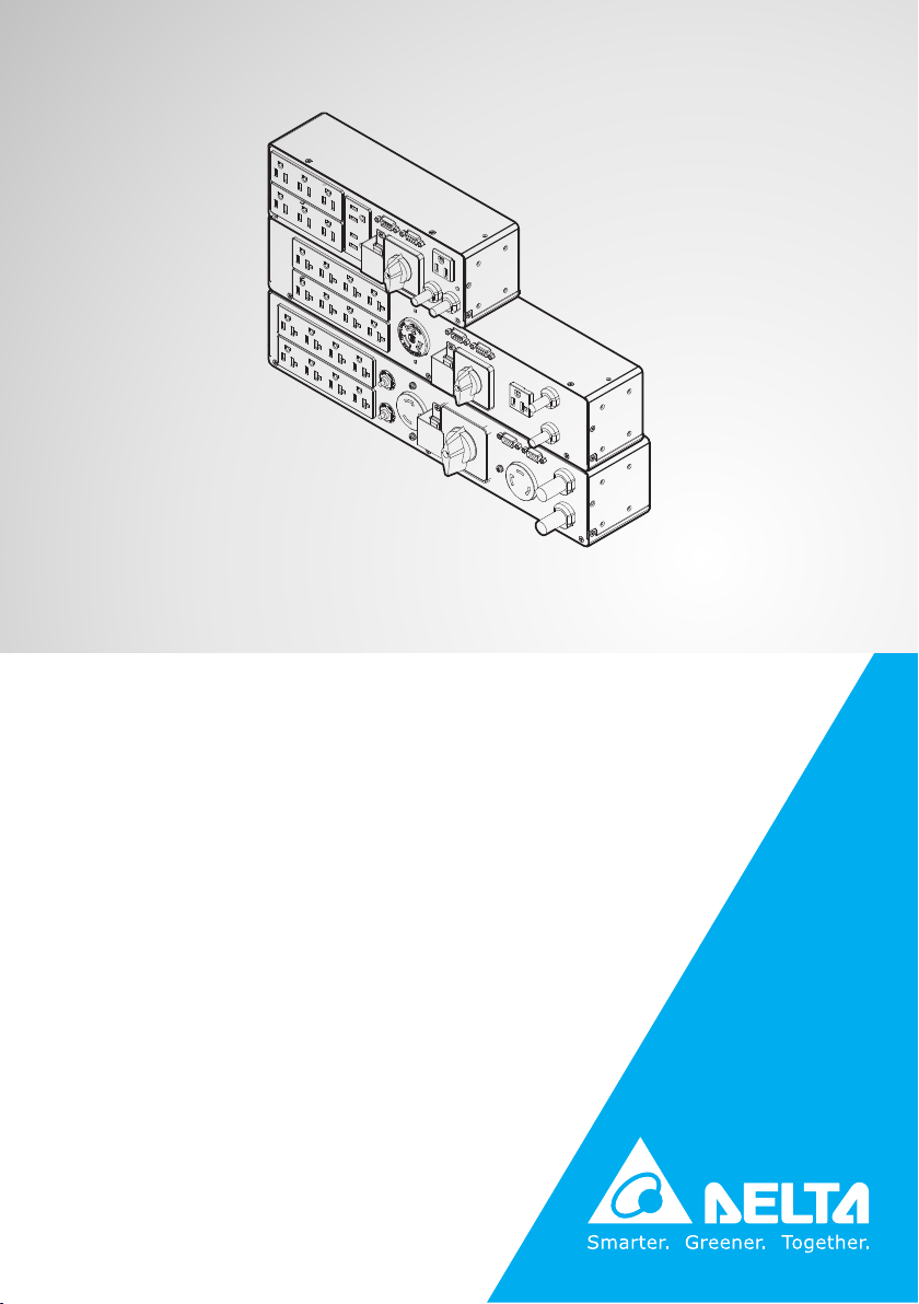
Delta UPS - Amplon Family
RT Series, Single Phase
1/ 1.5/ 2/ 3 kVA
Maintenance Bypass Box
User Manual
www.deltapowersolutions.com
Page 2

Save This Manual
This manual contains important instructions and warnings that you should
follow during the installation, operation, storage and maintenance of this
product. Failure to heed these instructions and warnings will void the warranty.
Copyright © 2019 by Delta Electronics Inc. All Rights Reserved. All rights of this
User Manual (“Manual”), including but not limited to the contents, information,
and figures are solely owned and reserved by Delta Electronics Inc. (“Delta”).
The Manual can only be applied to the operation or the use of this product. Any
disposition, duplication, dissemination, reproduction, modification, translation,
extraction, or usage of this Manual in whole or in part is prohibited without the prior
written permission of Delta. Given that Delta will continuously improve and develop
the product, changes may be made to the information in this Manual at any time
without obligation to notify any person of such revision or changes. Delta will make
all possible efforts to secure the accuracy and the integrity of this Manual. Delta
disclaims any kinds or forms of warranty, guarantee, or undertaking, either expressly
or implicitly, including but not limited to the completeness, faultlessness, accuracy,
non-infringement, merchantability or tness for a particular purpose of the Manual.
Amplon RT Series
II
Page 3

Table of Contents
Table of Contents
Chapter 1 : Product Introduction --------------------------------------- 1
Chapter 2 : Important Safety Instructions --------------------------- 2
Chapter 3 : Package List -------------------------------------------------- 4
Chapter 4 : Standard Compliance -------------------------------------- 7
Chapter 5 : Rear View ------------------------------------------------------ 8
Chapter 6 : How to Install the Maintenance Bypass
Box on the UPS ---------------------------------------------10
Chapter 7 : How to Install the Maintenance Bypass
Box on the External Battery Pack --------------------13
Chapter 8 : How to Install the Maintenance
Bypass Box on the Rack ---------------------------------17
Chapter 9 : How to Install the Maintenance Bypass
Box into the Tower Stands ------------------------------23
Chapter 10 : Wiring ---------------------------------------------------------25
Chapter 11 : Start-up Operation ----------------------------------------27
Chapter 12 : Maintenance ------------------------------------------------28
Chapter 13 : Technical Specications -------------------------------30
Appendix 1 : Warranty ----------------------------------------------------33
III
Page 4

Page 5

Chapter 1 Product Introduction
Chapter 1 : Product Introduction
The Maintenance Bypass Box (MBB) is designed to operate in conjunction with the
Delta RT series 1 ~ 3kVA UPS. It ensures that the connected critical loads continue
to be powered by the input power during UPS maintenance or during the unlikely
event of a UPS failure.
1
Page 6

Chapter 2 : Important Safety Instructions
z
z
Only qualied service personnel can perform installation and maintenance of the
Maintenance Bypass Box.
z
z
The Maintenance Bypass Box must operate in conjunction with Delta RT series
1 ~ 3kVA UPS. Please refer to the following table.
Maintenance
Bypass Box
Model
Applicable to
Delta RT series
UPS Model
z
z
Before installation of the Maintenance Bypass Box, please completely turn o
MBB-RT-1.5K
PDB1115A1300B8
RT-1K
RT-1.5K
MBB-RT-2K
PDB1116A1300B8
RT-2K RT-3K
MBB-RT-3K
PDB1117A1300B8
the UPS and cut o the input power and battery power (if applicable).
z
z
To reduce the risk of re, only connect the Maintenance Bypass Box to a circuit
with branch circuit overcurrent protection in accordance with the National Electrical Code, ANSI/ NFPA 70 and the Canadian Electrical Code, Part 1, C22.1. The
suggested branch circuit breaker’s current capacity is listed in the table below.
Model
Maximum Current of
Branch Circuit Breaker
MBB-RT-1.5K (PDB1115A1300B8) 20A
MBB-RT-2K (PDB1116A1300B8) 20A
MBB-RT-3K (PDB1117A1300B8) 30A
z
z
Failure to properly install the Maintenance Bypass Box may result in severe
damage to your UPS or load equipment.
z
z
Please install the Maintenance Bypass Box in an indoor temperature controlled
environment that is free of conductive contaminants.
Amplon RT Series
2
Page 7

Chapter 2 Important Safety Instructions
z
z
Do not operate the unit in an extremely dusty/ unclean area or a location near
heating devices, water and excessive humidity. Do not expose the unit to direct
sunlight.
z
z
Select a location where provides good air circulation for the unit at all times.
z
z
Properly route power cords so they cannot be walked on or damaged.
z
z
The Maintenance Bypass Box must be well grounded due to a possible risk of
current leakage.
z
z
The Maintenance Bypass Box is not intended for use in direct patient care or
life support applications.
3
Page 8
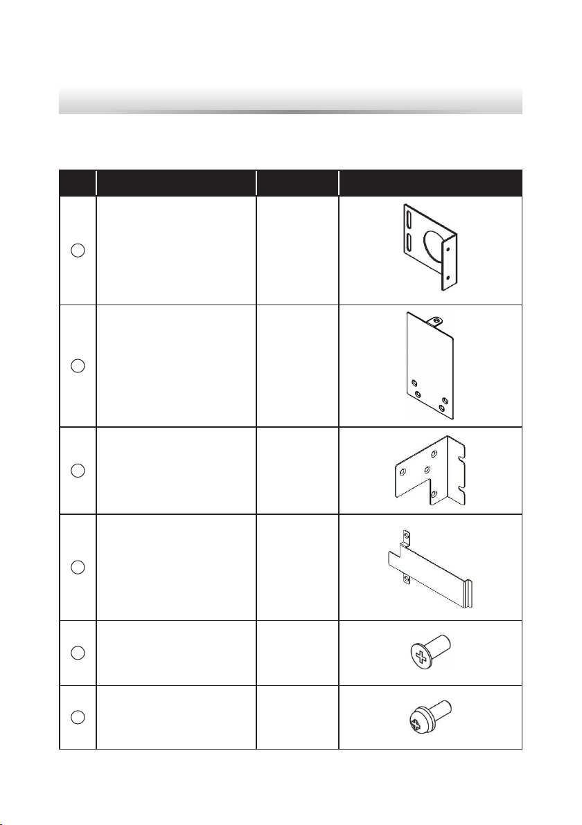
Chapter 3 : Package List
For PDB1115A1300B8
No. ITEM Q’ty Drawing
1
MBB EAR (For Rack) 2 PCS
2
MBB EAR (For Tower) 1 PC
3
MBB EAR (For Tower) 1 PC
4
UPS Output Cover 1 PC
5
M4 Screw (Flat Head) 4 PCS
6
M4 Screw (Pan Head) 2 PCS
Amplon RT Series
4
Page 9
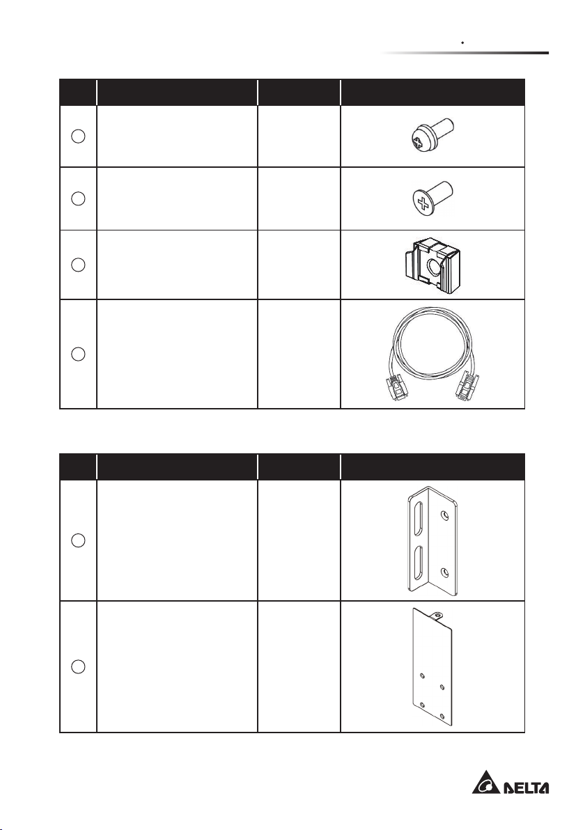
Chapter 3 Package List
No. ITEM Q’ty Drawing
7
M5 Screw 4 PCS
8
#6-32 Screw 3 PCS
9
M5 Cage Nut 4 PCS
10
RS-232 Cable 1 PC
For PDB1116A1300B8 & PDB1117A1300B8
No. ITEM Q’ty Drawing
1
MBB EAR (For Rack) 2 PCS
2
MBB EAR (For Tower) 1 PC
5
Page 10
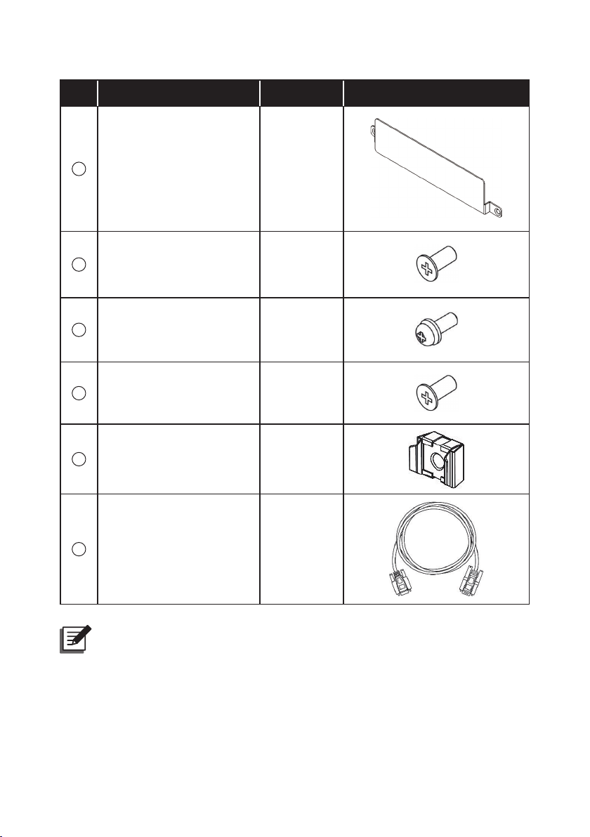
No. ITEM Q’ty Drawing
3
UPS Output Cover 1 PC
4
M4 Screw 4 PCS
5
M5 Screw 4 PCS
6
#6-32 Screw 4 PCS
7
M5 Cage Nut 4 PCS
8
RS-232 Cable 1 PC
NOTE :
1. If there is any damage or anything missing, please immediately contact
the dealer from whom you purchased the unit.
2. If the Maintenance Bypass Box needs to be returned, carefully repack
the Maintenance Bypass Box and all of the accessories using the original
packing material that came with the unit.
Amplon RT Series
6
Page 11

Chapter 4 : Standard Compliance
z
z
UL/ CE
z
z
IEC/ EN 62040-1
z
z
IEC/ EN 62040-2 CATEGORY C2
Chapter 4 Standard Compliance
7
Page 12
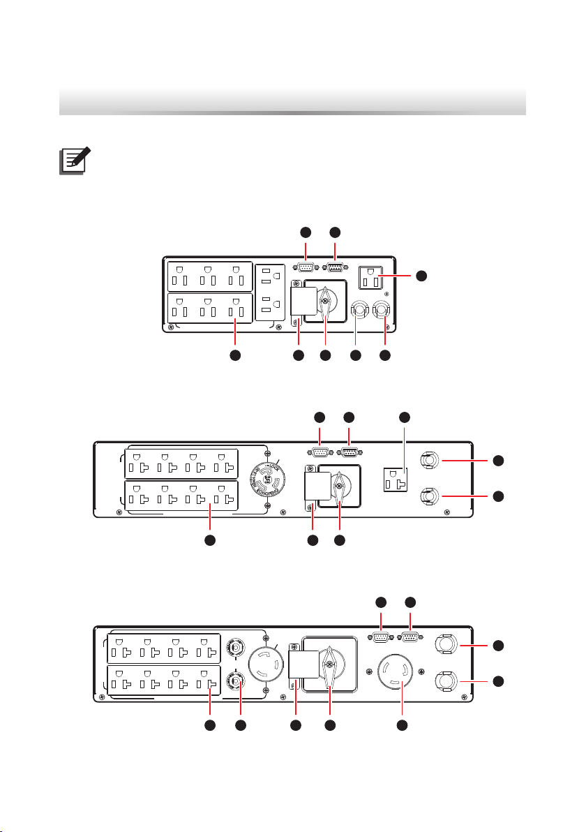
Chapter 5 : Rear View
NOTE :
There are no operational components or interfaces on the front of the MBB.
z
z
PDB1115A1300B8
7 8
UPS INPUT
z
z
PDB1116A1300B8
16A MAX. EACH BANK
(
12A MAX. EACH BANK & TOTAL OUTPUT
OUTPUT SOCKET
OUTPUT SOCKET(16A MAX. TOTAL OUTPUT
RS-232UPS RS-232
NORMAL
WARNING:
OPENING THIS COVER
PLATE WILL CAUSE
INVERTER SHUTDOWN.
ONLY AUTHORIZED
SERVICE PERSONNEL
CAN OPEN AND
OPERATE IT.
)
MANUAL BYPASS SWITCH
BY
PASS
AC INPUTUPS OUTPUT
2 15 46
16A MAX.
UPS RS-232 RS-232
NORMAL
WARNING:
OPENING THIS COVER
PLATE WILL CAUSE
INVERTER SHUTDOWN.
ONLY AUTHORIZED
SERVICE PERSONNEL
CAN OPEN AND
OPERATE IT.
)
MANUAL BYPASS SWITCH
BY
PASS
UPS INPUT
3
37 8
AC INPUT
UPS OUTPUT
1
2
z
z
PDB1117A1300B8
20A MAX. EACH BANK
Amplon RT Series
OUTPUT SOCKET
24A MAX. TOTAL OUTPUT
(
5 46
7 8
24A MAX.
BREAKER
)
WARNING:
OPENING THIS COVER
PLATE WILL CAUSE
INVERTER SHUTDOWN.
ONLY AUTHORIZED
SERVICE PERSONNEL
CAN OPEN AND
OPERATE IT.
NORMAL
MANUAL BYPASS SWITCH
PASS
RS-232UPS RS-232
BY
AC INPUT
1
2
UPS OUTPUTUPS INPUT
5 46 39
8
Page 13
No. Item Connection
1
AC Input Connects to the main AC utility.
2
UPS Output Connects to the UPS’s output socket.
3
UPS Input Connects to the UPS’s AC input power cord.
Chapter 5 Rear View
Manual Bypass
4
Switch
No connection is needed. The function is to switch
the UPS into manual bypass mode for maintenance
without power supply interruption.
No connection is needed. After you unscrew the
Manual Bypass
5
Switch Cover Plate
two screws shown in Figure 27 to remove the
cover plate, the MBB’s detector will automatically
activate and send a message to the UPS to ask it
to transfer into bypass mode.
6
Output Sockets Connect to the critical loads.
7
UPS RS-232 Connects to the UPS’s RS-232 port.
8
RS-232 Connects to your computer’s RS-232 port.
No connection is needed. The function is to prevent
9
Output Breakers
the output socket(s) from damage caused by
overload.
9
Page 14

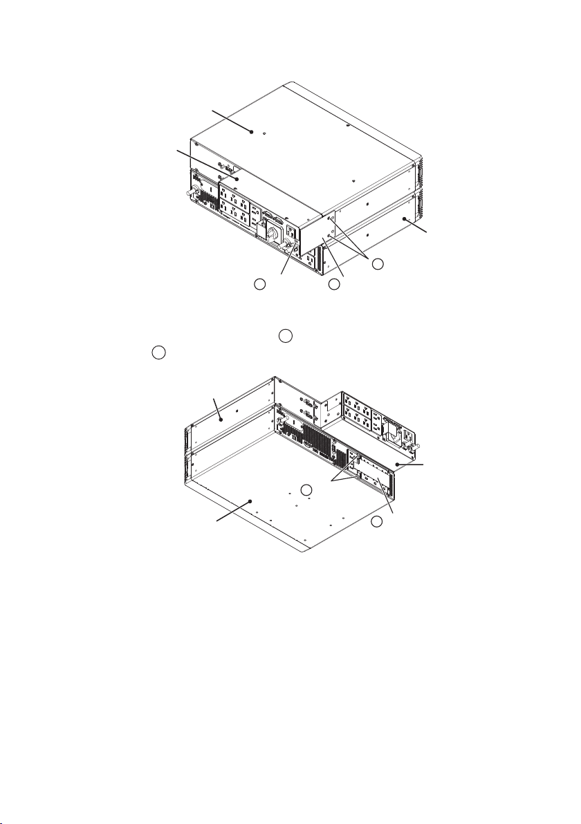
Chapter 6 : How to Install the
UPS
Maintenance Bypass Box on the UPS
NOTE :
1. In this User Manual, MBB means Maintenance Bypass Box.
2. For the meaning of
z
z
PDB1115A1300B8
1. Fix the MBB Ear (
screws (
6
5
). Please refer to Figure 1.
UPS
) and at the left side of the MBB with two pan-head M4 screws (
1
~ 10 shown in this chapter, please refer to Figure 3.
3
) on the top cover of the UPS with two at-head M4
6
× 2 PCS
3
× 1 PC
5
× 2 PCS
(Figure 1)
MBB
2. Fix the MBB Ear ( 2 ) at the right side of the UPS with two at-head M4
screws (
Please refer to Figure 2.
Amplon RT Series
5
) and at the right side of the MBB with one #6-32 screw ( 8 ).
MBB
8
× 1 PC
2
× 1 PC
5
× 2 PCS
(Figure 2)
10
Page 15

Chapter 6 How to Install the Maintenance
Bypass Box on the UPS
3. Install the UPS Output Cover ( 4 ) at the back of the UPS with two #6-32
screws (
z
z
PDB1116A1300B8/ PDB1117A1300B8
8
).
MBB
UPS
4
× 1 PC
8
× 2 PCS
(Figure 3)
NOTE :
Since models PDB1115A1300B8 and PDB1117A1300B8 have the same
standard accessories and the accessory installation methods are the
same, only model PDB1115A1300B8 is used for illustration (please see
Figure 4 ~ Figure 6).
1. Fix the MBB Ear (
2
) at the left side of the UPS with two M4 screws ( 4 )
and at the left side of the MBB with one #6-32 screw (
Figure 4.
UPS
6
× 1 PC
2
× 1 PC
(Figure 4)
11
4
× 2 PCS
MBB
6
). Please refer to
Page 16

2. Fix the MBB Ear ( 2 ) at the right side of the UPS with two M4 screws ( 4 )
and at the right side of the MBB with one #6-32 screw (
UPS
MBB
6
× 1 PC
× 1 PC
2
× 2 PCS
4
(Figure 5)
6
).
3. Install the UPS Output Cover ( 3 ) at the back of the UPS with two #6-32
screws (
6
).
MBB
UPS
3
× 1 PC
Amplon RT Series
(Figure 6)
12
6
× 2 PCS
Page 17

Chapter 7 How to Install the Maintenance
Bypass Box on the External Battery Pack
Chapter 7 : How to Install the Maintenance Bypass
Box on the External Battery Pack
NOTE :
1. In this User Manual, MBB means Maintenance Bypass Box.
2. For the meaning of
z
z
PDB1115A1300B8
1. Fix the MBB Ear (
head M4 screws (
screws (
5
). Please see Figure 7.
Battery Pack
1
~ 10 shown in this chapter, please refer to Figure 3.
3
) at the rear of the external battery pack with two pan-
6
) and at the left side of the MBB with two at-head M4
External
MBB
5
× 2 PCS
6
× 2 PCS
UPS
(Figure 7)
3
× 1 PC
2. Fix the MBB Ear ( 2 ) at the right side of the external battery pack with two
at-head M4 screws (
screw (
8
).
5
) and at the right side of the MBB with one #6-32
13
Page 18
External
Battery Pack
MBB
UPS
5
× 2 PCS
8
× 1 PC
2
× 1 PC
(Figure 8)
3. Install the UPS Output Cover ( 4 ) at the back of the UPS with two #6-32
screws (
8
).
External
Battery Pack
MBB
Amplon RT Series
UPS
8
(Figure 9)
14
× 2 PCS
4
× 1 PC
Page 19

z
× 2 PCS
z
PDB1116A1300B8/ PDB1117A1300B8
NOTE :
Since models PDB1115A1300B8 and PDB1117A1300B8 have the same
standard accessories and the accessory installation methods are the
same, only model PDB1115A1300B8 is used for illustration (please see
Figure 10 ~ Figure 12).
Chapter 7 How to Install the Maintenance
Bypass Box on the External Battery Pack
1. Fix the MBB Ear (
M4 screws (
UPS
2
) at the left side of the external battery pack with two
4
) and at the left side of the MBB with one #6-32 screw ( 6 ).
External
Battery Pack
6
× 1 PC
2
× 1 PC
4
(Figure 10)
MBB
2. Fix the MBB Ear ( 2 ) at the right side of the external battery pack with two
M4 screws (
4
) and at the right side of the MBB with one #6-32 screw ( 6 ).
External
MBB
Battery Pack
(Figure 11)
15
6
× 1 PC
2
4
× 2 PCS
× 1 PC
UPS
Page 20

3. Install the UPS Output Cover ( 3 ) at the back of the UPS with two #6-32
screws (
6
).
External
Battery Pack
MBB
3
× 1 PC
6
UPS
(Figure 12)
× 2 PCS
Amplon RT Series
16
Page 21
Chapter 8 How to Install the Maintenance
Bypass Box on the Rack
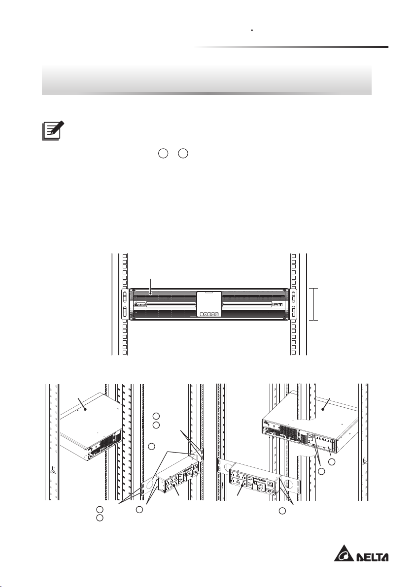
Chapter 8 : How to Install the Maintenance
Bypass Box on the Rack
NOTE :
1. In this User Manual, MBB means Maintenance Bypass Box.
2. For the meaning of
z
z
PDB1115A1300B8
Scenario 1: Only the UPS and MBB need to be installed on the rack. For such
application, the UPS must be installed at the front of the rack, the MBB at the
rear of the rack (see Figure 13 and Figure 14), and the total height is 2U (see
Figure 13)
1
~ 10 shown in this chapter, please refer to Figure 3.
UPS
ESC
Height :
2U
UPS
1
7
× 2 PCS5× 2 PCS
9
× 2 PCS
(Figure 13)
7
× 2 PCS
9
× 2 PCS
× 2 PCS
MBB MBB
(Figure 14)
17
5
× 2 PCS
UPS
4
8
× 2 PCS
× 1 PC
Page 22

For how to install, please refer to the following instructions.
1. Use the bracket ears provided in your RT 1-3kVA UPS to install the UPS at
the front of the rack. Please refer to Figure 13 and your UPS’s Installation
& Operation Quick Guide.
2. Use the four at-head M4 screws (
5
) to install the two MBB Ears ( 1 ) at
the left and right sides of the MBB. Please see Figure 14.
3. Fix the four M5 cage nuts (
9
) at the two sides of the rack. Please note
that the MBB should be installed at the rear of the rack. Please see Figure
14.
4. Use the four M5 screws (
9
).
5. Install the UPS Output Cover (
screws (
8
). Please see Figure 14.
7
) to secure the MBB on the rack’s M5 cage nuts (
4
) at the back of the UPS with two #6-32
Scenario 2: The UPS, MBB and external battery pack need to be installed
on the rack. For such application, the UPS and external battery pack must be
installed at the front of the rack, the MBB at the back of the external battery pack
(see Figure 15 and Figure 16), and the total height is 4U (see Figure 15).
External Battery Pack
BATTERY PACK
Height :
4U
ESC
Amplon RT Series
UPS
(Figure 15)
18
Page 23

Chapter 8 How to Install the Maintenance
Bypass Box on the Rack
8
× 1 PC2× 1 PC
5
× 2 PCS
MBB
5
× 2 PCS
3
× 1 PC
8
× 2 PCS
4
× 1 PC
UPS
External
Battery
Pack
6
× 2 PCS
(Figure 16)
For how to install, please refer to the following instructions.
1. Use the bracket ears provided in your RT 1-3kVA UPS to install the UPS at
the front of the rack. Please refer to Figure 15 and your UPS’s Installation
& Operation Quick Guide.
2. Use the bracket ears provided in your RT 1-3kVA external battery pack
to install the external battery pack at the front of the rack. Please refer to
Figure 15 and your external battery pack’s User Manual.
3. Fix the MBB Ear (
head M4 screws (
screws (
5
). Please see Figure 16.
3
) at the rear of the external battery pack with two pan-
6
) and at the left side of the MBB with two at-head M4
External
Battery
Pack
UPS
4. Fix the MBB Ear (
M4 screws (
2
) at the right side of the external battery pack with two
6
) and at the right side of the MBB with one #6-32 screw ( 8 ).
Please see Figure 16.
5. Install the UPS Output Cover (
screws (
z
z
PDB1116A1300B8/ PDB1117A1300B8
8
). Please see Figure 16.
NOTE :
Since models PDB1115A1300B8 and PDB1117A1300B8 have the same
standard accessories and the accessory installation methods are the
same, only model PDB1115A1300B8 is used for illustration (please see
Figure 17 ~ Figure 20).
4
) at the back of the UPS with two #6-32
19
Page 24

Scenario 1: Only the UPS and MBB need to be installed on the rack. For such
application, the UPS must be installed at the front of the rack, the MBB at the
rear of the rack (see Figure 17 and Figure 18), and the total height is 2U (see
Figure 17).
UPS
Height :
ESC
(Figure 17)
2U
UPS
5
× 2 PCS
7
× 2 PCS
1
× 1 PC
MBB MBB
4
× 2 PCS
4
× 2 PCS1× 1 PC
3
× 1 PC
UPS
6
× 2 PCS
5
× 2 PCS
7
× 2 PCS
(Figure 18)
For how to install, please refer to the following instructions.
1. Use the bracket ears provided in your RT 1-3kVA UPS to install the UPS at
the front of the rack. Please refer to Figure 17 and your UPS’s Installation
& Operation Quick Guide.
2. Use the four M4 screws (
4
) to install the two MBB Ears ( 1 ) at the left
and right sides of the MBB. Please see Figure 18.
Amplon RT Series
20
Page 25

Chapter 8 How to Install the Maintenance
Bypass Box on the Rack
3. Fix the four M5 cage nuts ( 7 ) at the two sides of the rack. Please note
that the MBB should be installed at the rear of the rack. Please see Figure
18.
4. Use the four M5 screws (
7
).
5. Install the UPS Output Cover (
screws (
6
). Please see Figure 18.
5
) to secure the MBB on the rack’s M5 cage nuts (
3
) at the back of the UPS with two #6-32
Scenario 2: The UPS, MBB and external battery pack need to be installed
on the rack. For such application, the UPS and external battery pack must be
installed at the front of the rack, the MBB at the rear of the rack (see Figure 19
and Figure 20), and the total height is 4U (see Figure 19).
External Battery Pack
BATTERY PACK
Height :
4U
ESC
UPS
(Figure 19)
External
Battery
Pack
UPS
1
× 1 PC
MBB MBB
5
× 2 PCS4× 2 PCS
7
× 2 PCS
(Figure 20)
21
4
× 2 PCS1× 1 PC
3
× 1 PC
6
× 2 PCS
5
× 2 PCS
7
× 2 PCS
External
Battery
Pack
UPS
Page 26

For how to install, please refer to the following instructions.
1. Use the bracket ears provided in your RT 1-3kVA UPS to install the UPS at
the front of the rack. Please refer to Figure 19 and your UPS’s Installation
& Operation Quick Guide.
2. Use the bracket ears provided in your RT 1-3kVA external battery pack
to install the external battery pack at the front of the rack. Please refer to
Figure 19 and your external battery pack’s User Manual.
3. Use the four M4 screws (
4
) to install the two MBB Ears ( 1 ) at the left
and right sides of the MBB. Please see Figure 20.
4. Fix the four M5 cage nuts (
7
) at the two sides of the rack. Please note
that the MBB should be installed at the rear of the rack. Please see Figure
20.
5. Use the four M5 screws (
7
). Please see Figure 20.
6. Install the UPS Output Cover (
screws (
6
). Please see Figure 20.
5
) to secure the MBB on the rack’s M5 cage nuts (
3
) at the back of the UPS with two #6-32
Amplon RT Series
22
Page 27
Chapter 9 How to Install the Maintenance
Bypass Box into the Tower Stands
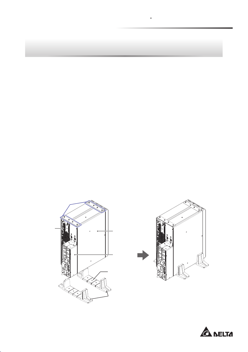
Chapter 9 : How to Install the Maintenance
Bypass Box into the Tower Stands
Please follow the procedures below and refer to Figure 21 ~ Figure 22 to install the
MBB into the tower stands.
1. Connect the tower stands (provided in your UPS’s package) to tower stand
extenders (provided in your external battery pack’s package) and adjust the total
width to 4U.
2. Follow Chapter 7: How to Install the Maintenance Bypass Box on the
External Battery Pack to x the MBB at the back of the external battery pack.
3. Upright the external battery pack with the MBB and place them into the tower
stands.
4. Upright the UPS and place it into the tower stands.
5. Use the fastener(s) provided in your external battery pack’s package to join the
top of the UPS and external battery pack together.
z
z
PDB1115A1300B8
Fasteners
UPS
External
Battery Pack
MBB
Tower Stand
Extenders
Tower Stands
(Figure 21)
23
Page 28
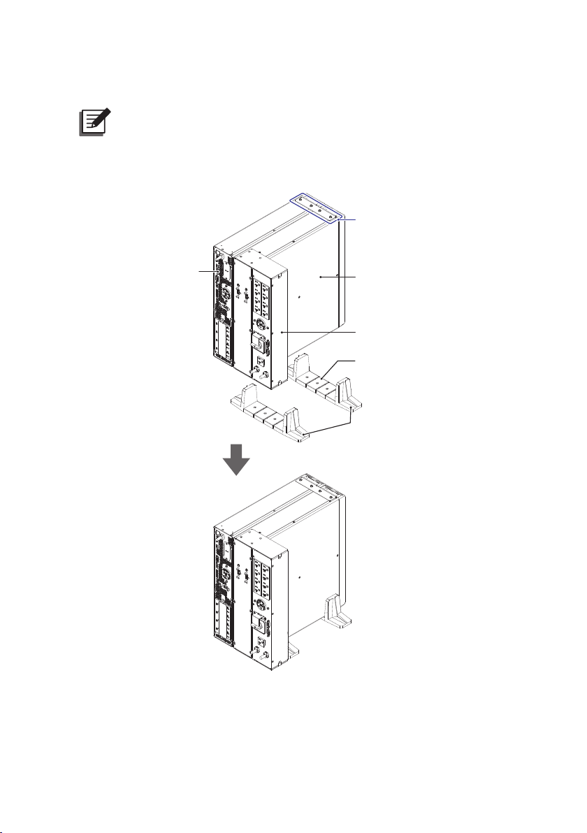
z
z
PDB1116A1300B8/ PDB1117A1300B8
NOTE :
Since models PDB1115A1300B8 and PDB1117A1300B8 have the same
installation methods, only model PDB1115A1300B8 is used for illustration
(see Figure 22).
Fastener
UPS
External
Battery Pack
MBB
Tower Stand
Extenders
Tower Stands
Amplon RT Series
(Figure 22)
24
Page 29

Chapter 10 Wiring
Chapter 10 : Wiring
WARNING:
1. Follow Chapter 2 : Important Safety Instructions.
2. When connecting the Maintenance Bypass Box to the mains and the
loads, you must install protective devices. The protective devices must be
approved components that meet safety certications.
3. Ensure that all of the breakers/ switches are in the OFF position before
wiring.
4. Please refer to the following gures for wiring connection with the UPS.
z
z
PDB1115A1300B8
External
Battery Pack
MBB
Main AC
Utility
UPS
RS-232 Cable
(Figure 23)
25
Page 30

z
z
PDB1116A1300B8
External
Battery Pack
z
z
PDB1117A1300B8
Main AC
Utility
MBB
UPS
RS-232 Cable
(Figure 24)
Main AC
Utility
MBB
External
Battery Pack
Amplon RT Series
UPS
RS-232 Cable
(Figure 25)
26
Page 31

Chapter 11 Start-up Operation
Chapter 11 : Start-up Operation
All the equipment and the UPS system must be properly connected and there must
be acceptable AC voltage present.
Please refer to your UPS’s Installation & Operation Quick Guide and external
battery pack’s User Manual for more information.
NOTE :
Do not remove the cover plate of the Maintenance Bypass Box’s MANUAL
BYPASS SWITCH during operation.
1. Verify if the MBB's AC power cord meets with N, L & G of the wall socket.
2. Plug the MBB's AC power cord into the wall socket.
3. Press and hold the ON button of the UPS for 3 seconds and release it after you
hear one beep.
4. Follow below to set up the UPS.
a. Setting → Output → Standby Mode → Bypass output
b. Setting → Dry Contact Setting → DB9 - Manual Bypass → Enable
5. Press and hold the ON/ OFF button of the UPS for 3 seconds and release it after
you hear one beep to turn on the UPS to ONLIN mode.
ONLINE
Input
Output
100
120.0V
120.0V
(Figure 26)
27
%
60.0Hz
60.0Hz
1 2
75
%
Page 32

Chapter 12 : Maintenance
BY
PASS
BYPASS Position
1. Unscrew the screws shown in Figure 27 to remove the cover plate of the
MANUAL BYPASS SWITCH.
UPS INPUT
RS-232UPS RS-232
NORMAL
WARNING:
OPENING THIS COVER
PLATE WILL CAUSE
INVERTER SHUTDOWN.
ONLY AUTHORIZED
SERVICE PERSONNEL
CAN OPEN AND
OPERATE IT.
(
12A MAX. EACH BANK & TOTAL OUTPUT
OUTPUT SOCKET
)
(Figure 27)
NOTE :
Under the cover plate, there is a manual bypass detector (please
see Figure 28). Once the cover plate is removed, the detector will
automatically activate to send a message to the UPS. The message is to
ask the UPS to transfer into bypass mode. If there is a power interruption
while the UPS is running in bypass mode, the connected loads won’t be
protected.
(
12A MAX. EACH BANK & TOTAL OUTPUT
OUTPUT SOCKET
)
MANUAL BYPASS SWITCH
RS-232UPS RS-232
NORMAL
MANUAL BYPASS SWITCH
BY
PASS
UPS INPUT
BY
PASS
Screws
AC INPUTUPS OUTPUT
AC INPUTUPS OUTPUT
2. After you confirm that the UPS has been run in bypass mode, switch the
Amplon RT Series
Manual Bypass Detector
(Figure 28)
MANUAL BYPASS SWITCH to the BYPASS position (please see Figure 29).
UPS INPUT
RS-232UPS RS-232
NORMAL
AC INPUTUPS OUTPUT
OUTPUT SOCKET
(
12A MAX. EACH BANK & TOTAL OUTPUT
(Figure 29)
MANUAL BYPASS SWITCH
)
28
Page 33

Chapter 12 Maintenance
NOTE :
If there is a power interruption while the MANUAL BYPASS SWITCH is in
the BYPASS position, the connected loads won’t be protected.
3. Disconnect the power cables from the ‘UPS INPUT’ and ‘UPS OUTPUT’ of the
Maintenance Bypass Box.
4. Disconnect all of the communication cables from the rear panel of the UPS.
5. Now, the UPS and the external battery pack(s) can be removed to perform
maintenance.
6. Once the maintenance is completed, re-install the UPS and the external battery
pack(s).
7. Reconnect all of the power cables, battery cables and communication cables.
8. After you confirm that the UPS has been run in bypass mode, switch the
Maintenance Bypass Box’s MANUAL BYPASS SWITCH to the NORMAL
position (please see Figure 30).
UPS INPUT
RS-232UPS RS-232
NORMAL
BY
PASS
OUTPUT SOCKET
(
12A MAX. EACH BANK & TOTAL OUTPUT
MANUAL BYPASS SWITCH
)
AC INPUTUPS OUTPUT
NORMAL Position
(Figure 30)
9. Re-install the cover plate of the MANUAL BYPASS SWITCH on the Maintenance
Bypass Box. This will automatically inactivate the manual bypass detector.
10. Make sure that the AC input is normal. After conrmation, press and hold the
ON/ OFF button of the UPS for 3 seconds and release it after you hear one beep
to turn on the UPS to ONLIN mode.
29
Page 34

Chapter 13 : Technical Specications
Part No. PDB1115A1300B8
Rated Voltage 100/110/115/120Vac
Input
Output Power Factor 12A
Connection
(Please refer to
the printed text
shown on the
rear of the MBB
(see Page 8)).
Environment
Physical
Rated Frequency 50/60 Hz
Rated Current 12A
'AC INPUT' NEMA 5-15P
'UPS INPUT' NEMA 5-15R
'UPS OUTPUT' NEMA 5-15P
'OUTPUT SOCKET' NEMA 5-15R × 8
'UPS RS-232' DB9 Male
'RS-232' DB9 Female
Operating
Temperature
Storage
Temperature
Relative Humidity 0 ~ 95% (non-condensing)
0 ~ 3000m (0 ~ 10000 ft);
Operating Altitude
Dimensions
(W × D × H)
Weight 1.92 kg (4.2 lb)
0 ~ 1000m (0 ~ 3300 ft)
0 ~ 50°C
(32 ~ 122°F)*
-15 ~ 50°C
(-59 ~ 122°F)
(without de-rating)
270 × 75 × 88 mm
(10.6 x 3.0 x 3.5 inch)
1
Amplon RT Series
30
Page 35

Chapter 13 Technical Specications
Part No. PDB1116A1300B8
Rated Voltage 100/110/115/120Vac
Input
Rated Frequency 50/60 Hz
Rated Current 16A
Output Power Factor 16A
'AC INPUT' NEMA 5-20P
Connection
'UPS INPUT' NEMA 5-20R
(Please refer to
the printed text
shown on the
'UPS OUTPUT' NEMA L5-20P
'OUTPUT SOCKET' NEMA 5-15/20R x 8, L5-20R x 1
rear of the MBB
(see Page 8)).
'UPS RS-232' DB9 Male
'RS-232' DB9 Female
Environment
Operating
Temperature
Storage
Temperature
Relative Humidity 0 ~ 95% (non-condensing)
0 ~ 50°C
(32 ~ 122°F)*
-15 ~ 50°C
(-59 ~ 122°F)
0 ~ 3000m (0 ~ 10000 ft);
Operating Altitude
0 ~ 1000m (0 ~ 3300 ft)
(without de-rating)
Physical
Dimensions
(W × D × H)
440 × 75 × 88 mm
(17.3 x 3.0 x 3.5 inch)
Weight 2.88 kg (6.3 lb)
1
31
Page 36

Part No. PDB1117A1300B8
Rated Voltage 100/110/115/120Vac
Input
Rated Frequency 50/60 Hz
Rated Current 24A
Output Power Factor 24A
'AC INPUT' NEMA L5-30P
Connection
'UPS INPUT' NEMA L5-30R
(Please refer to
the printed text
shown on the
'UPS OUTPUT' NEMA L5-30P
'OUTPUT SOCKET' NEMA 5-15/20R x 8, L5-30R x 1
rear of the MBB
(see Page 8)).
'UPS RS-232' DB9 Male
'RS-232' DB9 Female
Operating Temperature
Storage Temperature
0 ~ 50°C
(32 ~ 122°F)*
-15 ~ 50°C
(-59 ~ 122°F)
Environment
Relative Humidity 0 ~ 95% (non-condensing)
0 ~ 3000m (0 ~ 10000 ft);
Operating Altitude
0 ~ 1000m (0 ~ 3300 ft)
(without de-rating)
Physical
Dimensions
(W × D × H)
440 × 85 × 88 mm
(17.3 x 3.3 x 3.5 inch)
Weight 4.12 kg (9.1 lb)
1
NOTE :
1. *1 When the operating temperature is at 40 ~ 50°C (104 ~ 122°F), the
UPS will be de-rated to 80% of its capacity.
2. Refer to the rating label for the safety rating.
3. All specications are subject to change without prior notication.
Amplon RT Series
32
Page 37

Appendix 1 Warranty
Appendix 1 : Warranty
Seller warrants this product, if used in accordance with all applicable instructions,
to be free from original defects in material and workmanship within the warranty
period. If the product has any failure problem within the warranty period, Seller will
repair or replace the product at its sole discretion according to the failure situation.
This warranty does not apply to normal wear or to damage resulting from improper
installation, operation, usage, maintenance or irresistible force (i.e. war, fire,
natural disaster, etc.), and this warranty also expressly excludes all incidental and
consequential damages.
Maintenance service for a fee is provided for any damage out of the warranty
period. If any maintenance is required, please directly contact the supplier or Seller.
WARNING:
The individual user should take care to determine prior to use whether the
environment and the load characteristic are suitable, adequate or safe for
the installation and the usage of this product. The User Manual must be
carefully followed. Seller makes no representation or warranty as to the
suitability or tness of this product for any specic application.
No. 501327220000
Version : V 0.0
Release Date : 2019_04_29
33
Page 38

Page 39

Page 40

5013272200
 Loading...