

Delta M88H_122 (CF) Quick Installation Manual

Solar power inverter
M88H_121 (ST, product version J)
M88H_122 (CF, product version D)
Quick Installation Guide
United KingdomEurope

This quick installation guide applies for the following
inverter models:
● M88H_121 (with DC terminal block, Delta part number
RPI883M121200, Product Version J)
● M88H_122 (with DC connections of Multi-Contact and
String fuses, Delta part number RPI883M122000, Product Version D)
with rmware versions:
DSP: 1.33 / RED: 1.03 / COM: 1.16 or higher
The Delta part number can be found on the type plate of the
inverter. The Product Version is shown by the last letters of the
serial number, which is also located on the type plate. The rmware versions are listed on the display in the Inverter Info.
menu.
The Delta manuals undergo continuous revision in order to provide you with complete information regarding the installation and
operation of our inverters. Therefore, before starting installation
work, always consult www.solar-inverter.com to check whether
a newer version of the Quick Installation Guide or of the comprehensive Installation and Operation Manual is available.
© Copyright – Delta Electronics (Netherlands) B.V. – All rights
reserved.
This manual is intended for installers.
The information in this manual is to be treated as condential and
no part of this manual may be reproduced without prior written
permission from Delta Electronics. The information in this manual
may not be used for any purpose not directly connected to the
use of the inverter.
All information and specications can be modied without prior
notice.
All translations of this manual not authorized by Delta Electronics
(Netherlands) B.V. must include the annotation: "Translation of
the original operation manual".
Delta Electronics (Netherlands) B.V.
Tscheulinstraße 21
79331 Teningen
Germany
Authorized representative for this product in the EU:
Delta Electronics (Netherlands) B.V.
Zandsteen 15
2132 MZ Hoofddorp
Netherlands

3
Quick Installation Guide for Solar Power Inverter M88H EU V3 EN 5013240202 02 2018-03-22
Table of Contents
Basic safety instructions. . . . . . . . . . . . . . . . . . . . . . . . . . . . . . . . . . . . . . . . . . . . . . . . . . . . . . . . .4
Scope of delivery – M88H_121 (ST)
. . . . . . . . . . . . . . . . . . . . . . . . . . . . . . . . . . . . . . . . . . . . . . . . . . . 6
Scope of delivery – M88H_122 (CF)
. . . . . . . . . . . . . . . . . . . . . . . . . . . . . . . . . . . . . . . . . . . . . . . . . . .7
Components of the M88H_121 (ST) inverter
. . . . . . . . . . . . . . . . . . . . . . . . . . . . . . . . . . . . . . . . . . . . . . 8
Components of the M88H_122 (CF) inverter
. . . . . . . . . . . . . . . . . . . . . . . . . . . . . . . . . . . . . . . . . . . . . 10
Display, buttons, and LEDs
. . . . . . . . . . . . . . . . . . . . . . . . . . . . . . . . . . . . . . . . . . . . . . . . . . . . . . 12
Information on the type plate
. . . . . . . . . . . . . . . . . . . . . . . . . . . . . . . . . . . . . . . . . . . . . . . . . . . . . 12
Hazard zones in the wiring box
. . . . . . . . . . . . . . . . . . . . . . . . . . . . . . . . . . . . . . . . . . . . . . . . . . . . 13
Planning the installation
. . . . . . . . . . . . . . . . . . . . . . . . . . . . . . . . . . . . . . . . . . . . . . . . . . . . . . . . 14
Dimensions
. . . . . . . . . . . . . . . . . . . . . . . . . . . . . . . . . . . . . . . . . . . . . . . . . . . . . . . . . . . . . . . 16
AC and DC cable requirements – M88H_121 (ST)
. . . . . . . . . . . . . . . . . . . . . . . . . . . . . . . . . . . . . . . . . . 18
AC and DC terminal blocks - general information
. . . . . . . . . . . . . . . . . . . . . . . . . . . . . . . . . . . . . . . . . . 18
AC cable
. . . . . . . . . . . . . . . . . . . . . . . . . . . . . . . . . . . . . . . . . . . . . . . . . . . . . . . . . . . . . . . 19
DC cables
. . . . . . . . . . . . . . . . . . . . . . . . . . . . . . . . . . . . . . . . . . . . . . . . . . . . . . . . . . . . . . 19
AC and DC cable requirements – M88H_122 (CF)
. . . . . . . . . . . . . . . . . . . . . . . . . . . . . . . . . . . . . . . . . . 20
AC cable
. . . . . . . . . . . . . . . . . . . . . . . . . . . . . . . . . . . . . . . . . . . . . . . . . . . . . . . . . . . . . . . 20
DC cables
. . . . . . . . . . . . . . . . . . . . . . . . . . . . . . . . . . . . . . . . . . . . . . . . . . . . . . . . . . . . . . 21
Special instructions for the use of aluminum cables
. . . . . . . . . . . . . . . . . . . . . . . . . . . . . . . . . . . . . . . . 22
Communications cable requirements
. . . . . . . . . . . . . . . . . . . . . . . . . . . . . . . . . . . . . . . . . . . . . . . . . 24
Routing the cables
. . . . . . . . . . . . . . . . . . . . . . . . . . . . . . . . . . . . . . . . . . . . . . . . . . . . . . . . . . . 25
Mounting the inverter
. . . . . . . . . . . . . . . . . . . . . . . . . . . . . . . . . . . . . . . . . . . . . . . . . . . . . . . . . . 26
Grounding the inverter housing
. . . . . . . . . . . . . . . . . . . . . . . . . . . . . . . . . . . . . . . . . . . . . . . . . . . . 29
Connecting the mains (AC) – general notes
. . . . . . . . . . . . . . . . . . . . . . . . . . . . . . . . . . . . . . . . . . . . . 30
Connecting the mains (AC) – Cable gland M88H_121 (ST)
. . . . . . . . . . . . . . . . . . . . . . . . . . . . . . . . . . . . . 32
Connecting the mains (AC) – Cable gland M88H_122 (CF)
. . . . . . . . . . . . . . . . . . . . . . . . . . . . . . . . . . . . . 34
Connecting the mains (AC) – Tips for M88H_121 (ST)
. . . . . . . . . . . . . . . . . . . . . . . . . . . . . . . . . . . . . . . . 36
Connecting the mains (AC) – Tips for M88H_122 (CF)
. . . . . . . . . . . . . . . . . . . . . . . . . . . . . . . . . . . . . . . . 37
Connecting solar modules (DC) – cable gland M88H_121 (ST)
. . . . . . . . . . . . . . . . . . . . . . . . . . . . . . . . . . . 38
Connecting solar modules (DC) – 1-/2-MPPT operation M88H_121 (ST)
. . . . . . . . . . . . . . . . . . . . . . . . . . . . . . 39
Connecting solar modules (DC) – M88H_122 (CF)
. . . . . . . . . . . . . . . . . . . . . . . . . . . . . . . . . . . . . . . . . . 41
Closing the wiring box
. . . . . . . . . . . . . . . . . . . . . . . . . . . . . . . . . . . . . . . . . . . . . . . . . . . . . . . . . 44
Overview of communications card
. . . . . . . . . . . . . . . . . . . . . . . . . . . . . . . . . . . . . . . . . . . . . . . . . . 45
Connecting a data logger via RS485
. . . . . . . . . . . . . . . . . . . . . . . . . . . . . . . . . . . . . . . . . . . . . . . . . 46
Connecting the digital inputs, dry contacts and external power-off (optional)
. . . . . . . . . . . . . . . . . . . . . . . . . . . 47
Attaching warning labels to the inverter
. . . . . . . . . . . . . . . . . . . . . . . . . . . . . . . . . . . . . . . . . . . . . . . 48
Commissioning – basic settings
. . . . . . . . . . . . . . . . . . . . . . . . . . . . . . . . . . . . . . . . . . . . . . . . . . . . 49
Date and time
. . . . . . . . . . . . . . . . . . . . . . . . . . . . . . . . . . . . . . . . . . . . . . . . . . . . . . . . . . . . 50
Inverter ID
. . . . . . . . . . . . . . . . . . . . . . . . . . . . . . . . . . . . . . . . . . . . . . . . . . . . . . . . . . . . . . 50
Baud rate for RS485
. . . . . . . . . . . . . . . . . . . . . . . . . . . . . . . . . . . . . . . . . . . . . . . . . . . . . . . . . 51
AC connection type
. . . . . . . . . . . . . . . . . . . . . . . . . . . . . . . . . . . . . . . . . . . . . . . . . . . . . . . . . . 51
External power-off (EPO)
. . . . . . . . . . . . . . . . . . . . . . . . . . . . . . . . . . . . . . . . . . . . . . . . . . . . . . . 52
Active power limitation
. . . . . . . . . . . . . . . . . . . . . . . . . . . . . . . . . . . . . . . . . . . . . . . . . . . . . . . . 52
Dry contacts (relays)
. . . . . . . . . . . . . . . . . . . . . . . . . . . . . . . . . . . . . . . . . . . . . . . . . . . . . . . . . 53
Technical Data – M88H_121 (ST)
. . . . . . . . . . . . . . . . . . . . . . . . . . . . . . . . . . . . . . . . . . . . . . . . . . . . 54
Technical data – M88H_122 (CF)
. . . . . . . . . . . . . . . . . . . . . . . . . . . . . . . . . . . . . . . . . . . . . . . . . . . . 56
Customer Service - Europe
. . . . . . . . . . . . . . . . . . . . . . . . . . . . . . . . . . . . . . . . . . . . . . . . . . . . . . 60
4
Quick Installation Guide for Solar Power Inverter M88H EU V3 EN 5013240202 02 2018-03-22
Basic safety instructions
Safety instructions for all M88H
WARNING
Electric shock
When the cover is removed from the wiring box,
this exposes voltage-carrying parts and protection conforming to IP65 is no longer guaranteed.
► Remove the cover only when absolutely
necessary.
► Do not remove the cover if water or dirt
might enter the inverter.
► After work is completed, ensure that the
cover is properly replaced and screwed in.
Check that the cover is properly sealed.
NOTICE
Incorrectly dimensioned solar system.
An solar system of the wrong size may cause
damage to the inverter.
► When calculating the module string, always
pay attention to technical data of the inverter
(input voltage range, maximum current
and maximum input power), see chapter
"Technical Data".
● To comply with the IEC 62109-5.3.3 safety requirements
and avoid injury or material damage, the inverter must be
installed and operated in accordance with the safety and
operating instructions set out in this manual. Delta Electronics is not responsible for damage resulting from failure to
follow the safety and operating instructions set out in this
manual.
● The inverter may only be installed and commissioned by
installers who have been trained and certied for the installation and operation of mains-based solar inverters.
● All repair work on the inverter must be carried out by Delta
Electronics. Otherwise, the warranty will be void.
● Warning instructions and warning symbols attached to the
inverter by Delta Electronics must not be removed.
● The inverter has a high leakage current value. The ground-
ing cable must be connected before commencing operation.
● Do not disconnect any cables while the inverter is under
load due to risk of a fault arc.
● To prevent damage due to lightning strikes, follow the provi-
sions that apply in your country.
● The surface of the inverter can get very hot during opera-
tion. Wear safety gloves when you touch the inverter (apart
from at the display).
● The inverter is very heavy. For hoisting and moving, use a
mechanical lifting device (e.g. crane or block and tackle).
At least three persons are required for manual hoisting and
moving.
● Only equipment in accordance with SELV (EN 60950) may
be connected to the RS485 interfaces.
● All connections must be sufciently insulated in order to
ensure the IP65 degree of protection. Unused connections
must be closed using cover caps.
Safety instructions for the M88H_121 (ST)
DANGER
Electric shock
Potentially fatal voltages are present at the
inverter during operation. When the inverter
is disconnected from all power sources, this
voltage remains in the inverter for up to 100
seconds.
Therefore, always carry out the following steps
before working on the inverter:
1. Disconnect the inverter from all AC and DC
voltage sources and make sure that none
of the connections can be accidentally
restored.
2. Wait at least 100 seconds until the internal
capacitors have discharged.
DANGER
Electric shock
Potentially fatal voltages are present at the
inverter DC connections. When light falls on the
solar modules, they immediately start to generate electricity. This also happens when light
does not fall directly on the solar modules.
► Never disconnect the inverter from the solar
modules when it is under load.
► Disconnect the connection to the mains so
that the inverter cannot supply energy to the
mains.
► Disconnect the inverter from all AC and DC
voltage sources. Ensure that none of the
connections can be restored accidentally.
► Ensure that the DC cables cannot be
touched accidentally.
5
Quick Installation Guide for Solar Power Inverter M88H EU V3 EN 5013240202 02 2018-03-22
Basic safety instructions
Safety instructions for the M88H_122 (CF)
DANGER
Electric shock
Potentially fatal voltages are present at the
inverter during operation. When the inverter
is disconnected from all power sources, this
voltage remains in the inverter for up to 100
seconds.
Therefore, always carry out the following steps
before working on the inverter
1. Turn the DC isolating switch to the 0 (OFF)
position.
2. Disconnect the inverter from all AC and DC
voltage sources and make sure that none
of the connections can be accidentally
restored.
3. Wait at least 100 seconds until the internal
capacitors have discharged.
DANGER
Electric shock
Potentially fatal voltages are present at the
inverter DC connections. When light falls on the
solar modules, they immediately start to generate electricity. This also happens when light
does not fall directly on the solar modules.
► Never disconnect the inverter from the solar
modules when it is under load.
► Turn the DC isolating switch to the 0 (OFF)
position.
► Disconnect the connection to the mains so
that the inverter cannot supply energy to the
mains.
► Disconnect the inverter from all AC and DC
voltage sources. Ensure that none of the
connections can be restored accidentally.
► Ensure that the DC cables cannot be
touched accidentally.
6
Quick Installation Guide for Solar Power Inverter M88H EU V3 EN 5013240202 02 2018-03-22
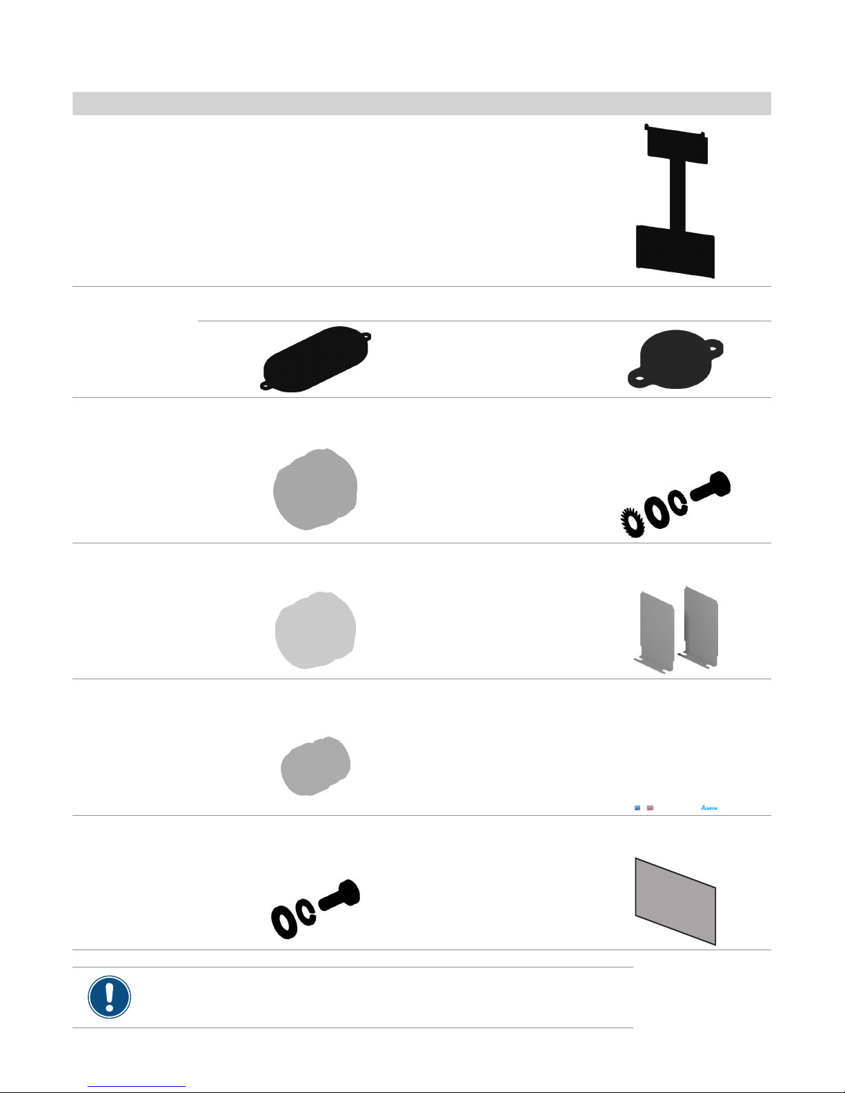
Scope of delivery – M88H_121 (ST)
Part Description Part Description
M88H_121 inverter
with wiring box
1
Mounting plate 1
Cover caps
For closing the upper cable feed-throughs on the junction box when the power module is removed from
the junction box. The cover caps are tted to the mounting plate.
2
1
Cable gland for AC
feed-through
1
For feeding the AC cable into the
junction box.
M6 grounding screw 1
For grounding the inverter housing;
with spring washer, washer and
toothed lock washer; mounted on
the inverter.
Cable gland for DC
feed-through
2
For feeding the DC cable into the
junction box.
Screening plate for the
air inlet
2
For covering the air inlets and preventing the entry of small animals.
Cable gland for the
communication connection
1
For fastening the communication
cables to the junction box.
Quick installation
guide and basic safety
instructions
1
Solar Power Inverters M88H_121 (ST) and M88H_122 (CF, Product Version D)
Quick Installation Guide
United KingdomEurope
M6 mounting screw 4
For fastening the wiring box to the
mounting plate; with spring washer
and washer.
Display cover 1
To protect the display against damage
Check the delivery for completeness and all components for damage before starting installation work.
Do not use any damaged components.
Keep the packaging.
7
Quick Installation Guide for Solar Power Inverter M88H EU V3 EN 5013240202 02 2018-03-22
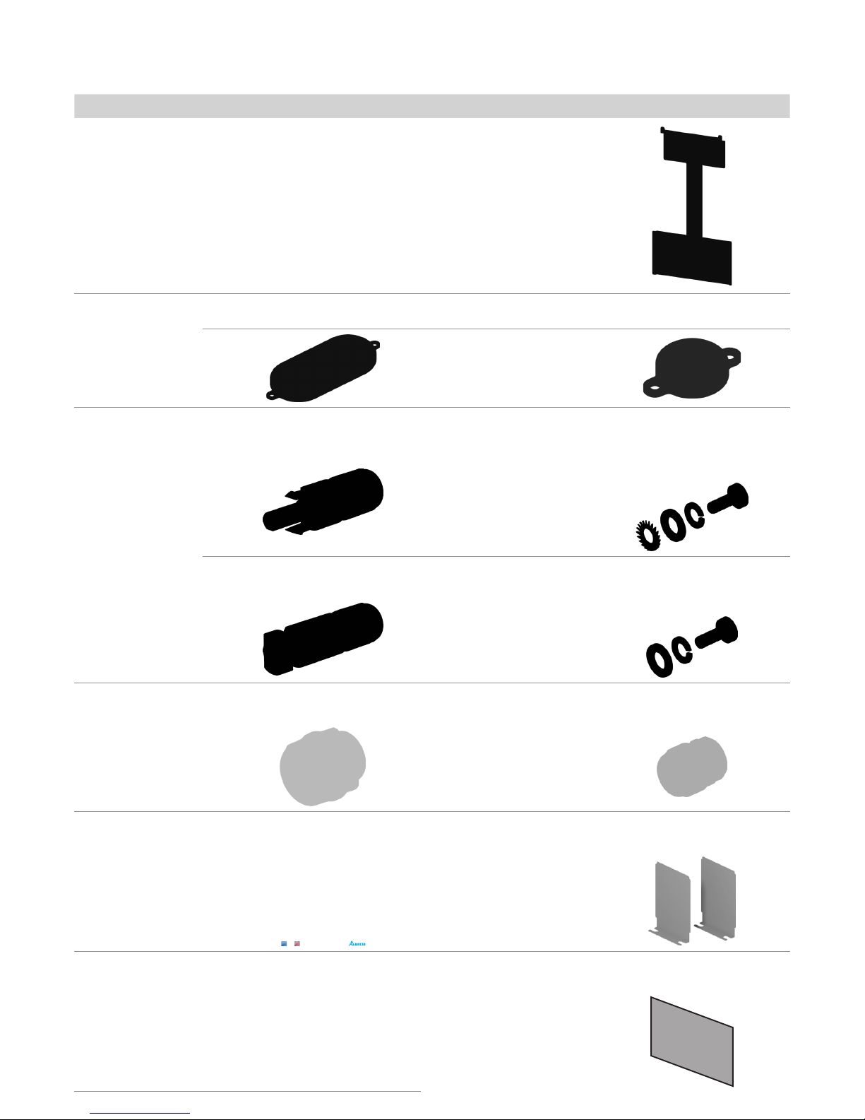
Scope of delivery – M88H_122 (CF)
Part Description Part Description
M88H_122 inverter
with wiring box
1
Mounting plate 1
Cover caps
For closing the upper cable feed-throughs on the wiring box when the inverter part is disconnected. The
cover caps are tted to the mounting plate.
2
1
DC plug
18
Multi-Contact MC4-plug for DC +
(32.0017P0001-UR for 4/6 mm2)
M6 grounding screw 1
For grounding the inverter housing;
with spring washer, washer and
toothed lock washer; mounted on
the inverter.
18
Multi-Contact MC4-plug for DC–
(32.0016P0001-UR for 4/6 mm2)
M6 mounting screw 4
For fastening the wiring box to the
mounting plate; with spring washer
and washer
Cable gland for the AC
connection
1
For feeding the AC cable into the
junction box
Cable gland for the
communication connection
1
For fastening the communication
cable to the wiring box
Quick installation
guide and basic safety
instructions
1
Solar Power Inverters M88H_121 (ST) and M88H_122 (CF, Product Version D)
Quick Installation Guide
United KingdomEurope
Screening plate for the
air inlet
2
For covering the air inlets and preventing the entry of small animals.
Display cover 1
To protect the display against damage
8
Quick Installation Guide for Solar Power Inverter M88H EU V3 EN 5013240202 02 2018-03-22
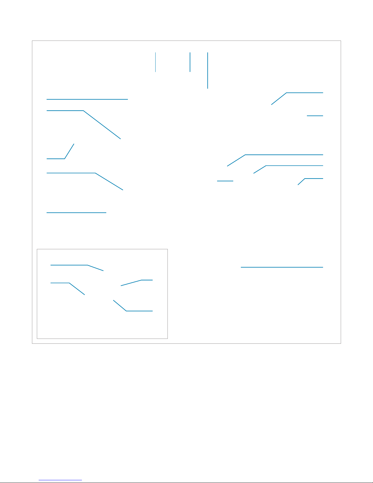
Components of the M88H_121 (ST) inverter
1 Power module 8 Grounding connection
2 Display, buttons, and LED 9 Mounting plate
3 Fan module 10 Cable gland for the communication connection
4 Filter for air outlet (2x) 11 Communication card
5 Filter for air inlet 12 AC cable gland
6 Cover panel for the air inlet (2x) 13 Cover panel for the wiring box
7 DC cable gland (2x)
11.1 RS485 connection
11.2 Digital inputs
11.3 Dry contacts
11.4 DIP switch for VCC and RS485 termination resistor
13
6.2
12
4.2
10
11
1 2
3
4.1
6.1
5
7
9
8
11
11.1
11.4
11.3
11.2
9
Quick Installation Guide for Solar Power Inverter M88H EU V3 EN 5013240202 02 2018-03-22
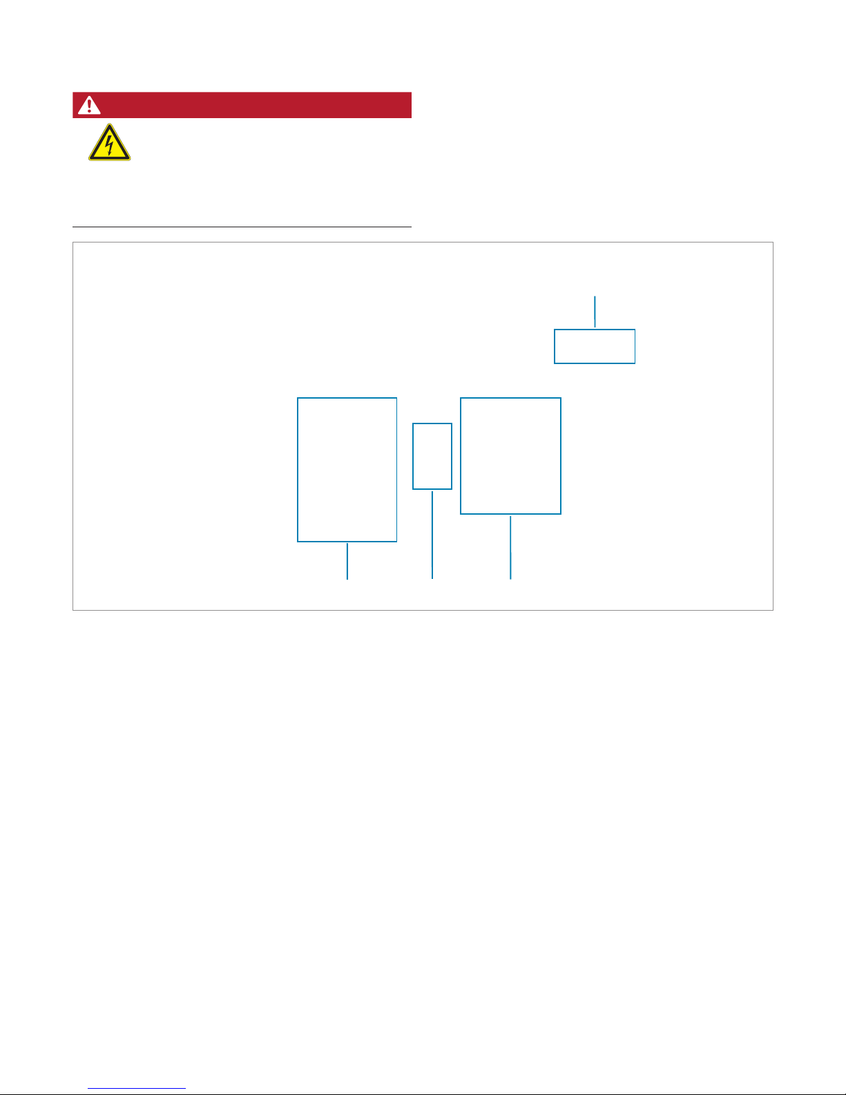
Components of the M88H_121 (ST) inverter
14 DC surge protection devices 16 AC surge protection devices
15 DC terminal block 17 AC terminal block
DANGER
Modied design of the DC connections
The design of the DC connections on the DC
terminal block has changed in comparison with
previous versions of the M88H_121 (ST)!
► You must comply with the correct use of plus
(+) and minus (-) when connecting the DC
cables.
14
1517
16
10
Quick Installation Guide for Solar Power Inverter M88H EU V3 EN 5013240202 02 2018-03-22
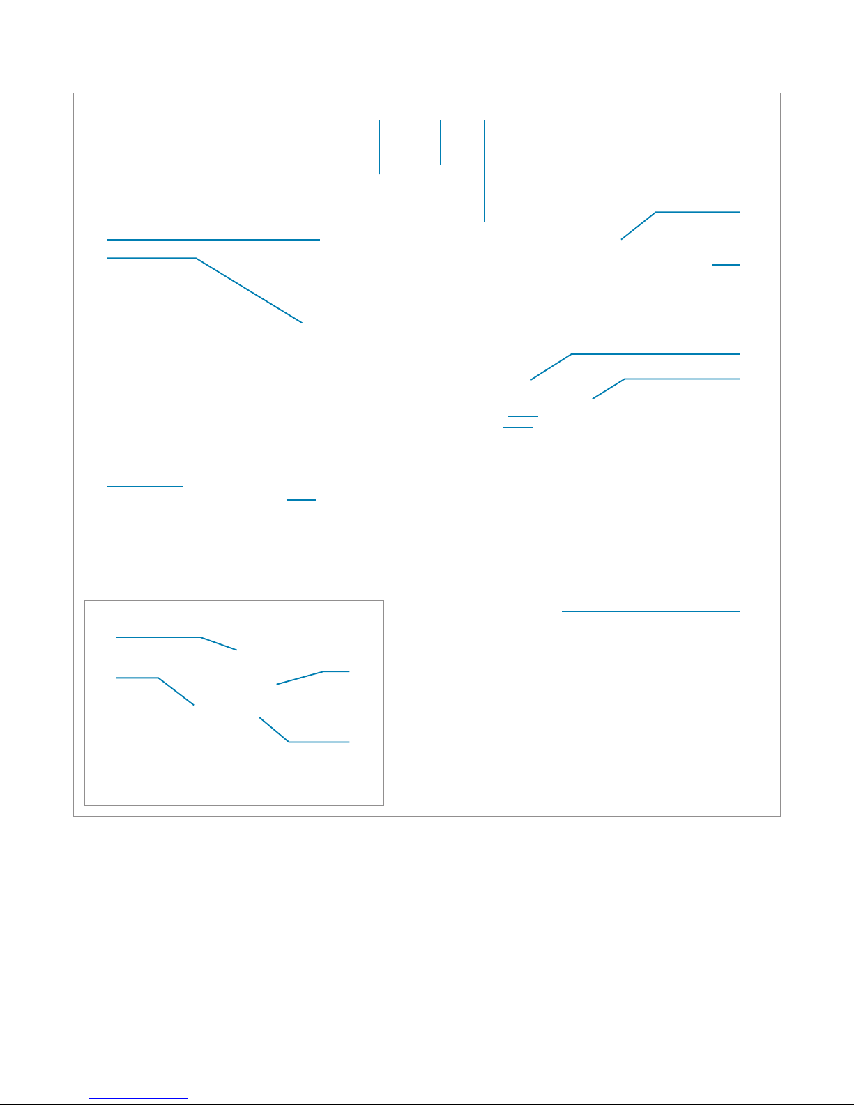
Components of the M88H_122 (CF) inverter
13
6.2
4.2
12
11
1 2
3
4.1
6.1
5
9
8
7
10
10.1
10.4
10.3
10.2
10
1 Power module 8 DC isolating switch
2 Display, buttons, and LED 9 Mounting plate
3 Fan module 10 Communication card
4 Filter for air outlet (2x) 11 Cable gland for the communication connection
5 Filter for air inlet 12 AC cable gland
6 Cover panel for the side air inlet (2x) 13 Cover panel for the wiring box
7 Grounding connection
10.1 RS485 connection
10.2 Digital inputs
10.3 Dry contacts
10.4 DIP switch for VCC and RS485 termination resistor
11
Quick Installation Guide for Solar Power Inverter M88H EU V3 EN 5013240202 02 2018-03-22
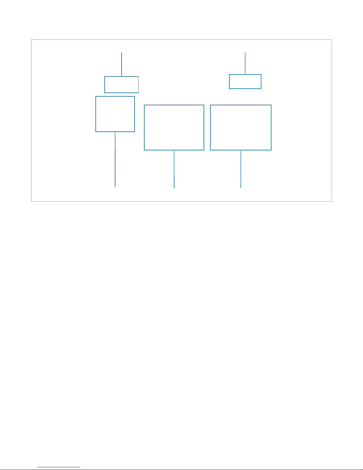
14
15
18
1617
14 AC surge protection devices 16 DC1 string fuses 18 AC terminal block
15 DC surge protection devices 17 DC2 string fuses
Components of the M88H_122 (CF) inverters
12
Quick Installation Guide for Solar Power Inverter M88H EU V3 EN 5013240202 02 2018-03-22
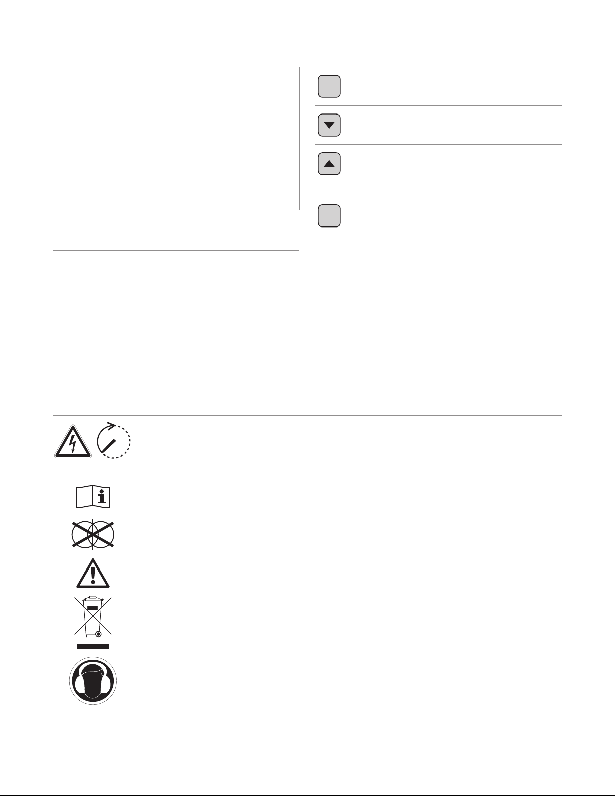
Display, buttons, and LEDs
100 seconds
Danger to life through electric shock
Potentially fatal voltage is present inside the inverter during operation and this voltage remains present for up to
100 seconds after disconnection from the power supply.
Only the wiring box may be opened. All other device parts may not be opened.
Before working on the inverter, read the supplied manual and follow the instructions contained therein.
This inverter is not separated from the grid by a transformer.
The housing of the inverter must be grounded if this is required by local regulations.
WEEE mark
The inverter must not be disposed of as standard household waste, but in accordance with the applicable electronic waste disposal regulations of your country or region.
This regulatory symbol does not apply to the EU because the noise level lies below the EU guidelines.
Information on the type plate
EXIT
EXIT
Exit the current menu.
Cancel the setting for a parameter.
Changes are not adopted.
Down
Move downwards in the menu.
Reduce the value of a congurable
parameter.
Up
Move upwards in the menu.
Increase the value of a congurable
parameter.
ENT
ENTER
Select menu item.
Open a congurable parameter for
editing.
Cancel the setting for a parameter.
Changes are adopted.
Grid
Grid
Green LED. Lights up when the
inverter is supplying electricity to the
mains grid.
AlArm
Alarm
Red LED. Indicates an error, a failure
or a warning.
13
Quick Installation Guide for Solar Power Inverter M88H EU V3 EN 5013240202 02 2018-03-22
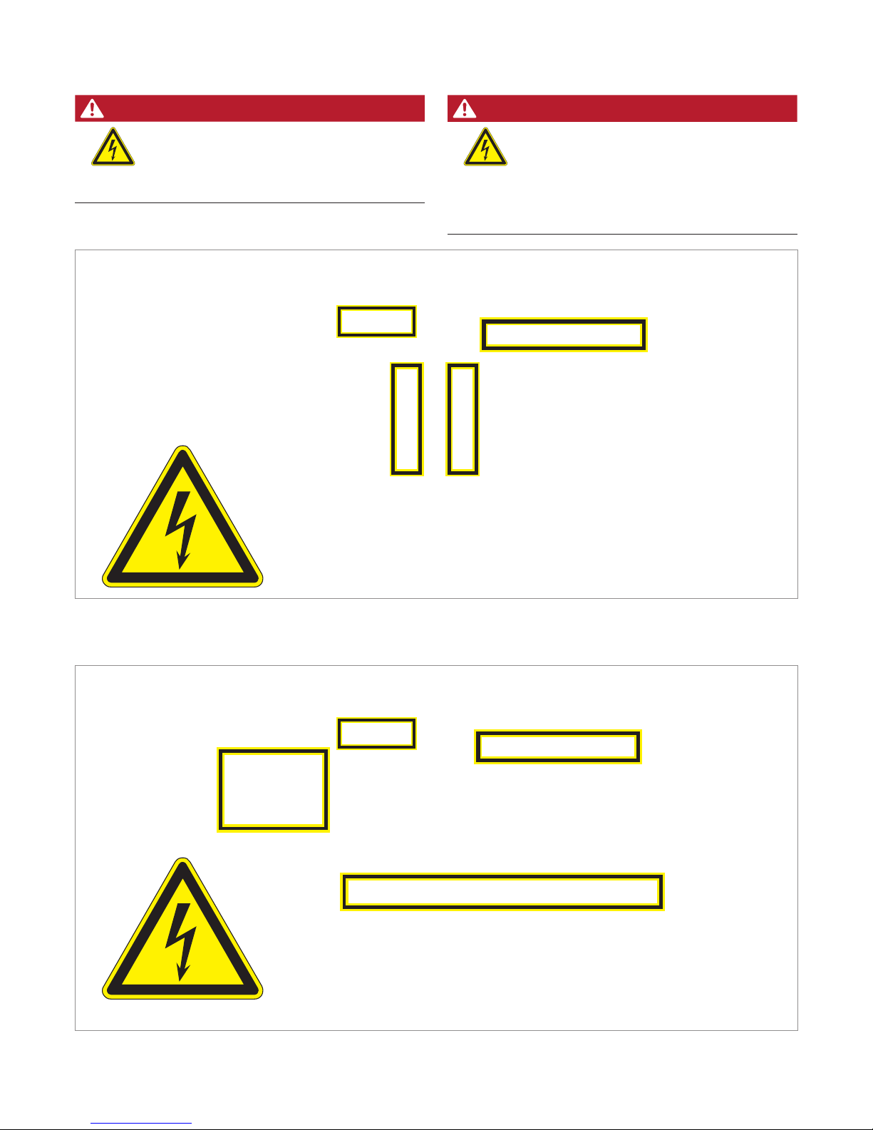
Hazard zones in the wiring box
DANGER
Modied design of the DC inputs
The design of the DC inputs on the DC terminal
block has changed in comparison with previous
versions of the M88H_121 (ST)!
► You must comply with the correct use of plus
(+) and minus (-) when connecting the DC
cables.
Hazard zones with potentially life-threatening currents and voltages – M88H_122 (CF)
Hazard zones with potentially life-threatening currents and voltages – M88H_121 (ST)
DANGER
Electric shock
The cover in the interior of the terminal box
does not need to be removed for cabling work.
All connections are accessible, even when the
internal cover is installed.
14
Quick Installation Guide for Solar Power Inverter M88H EU V3 EN 5013240202 02 2018-03-22
Outdoor installations
► The inverter has a protection degree of IP65 and can be
installed indoors and outdoors. Despite this, the inverter
should be protected by a roof against direct solar irradiation, rain and snow. For example, the power of the inverter
will be reduced if it is too heavily heated by solar radiation.
This is normal operating behavior for the inverter and is
necessary to protect the internal electronics.
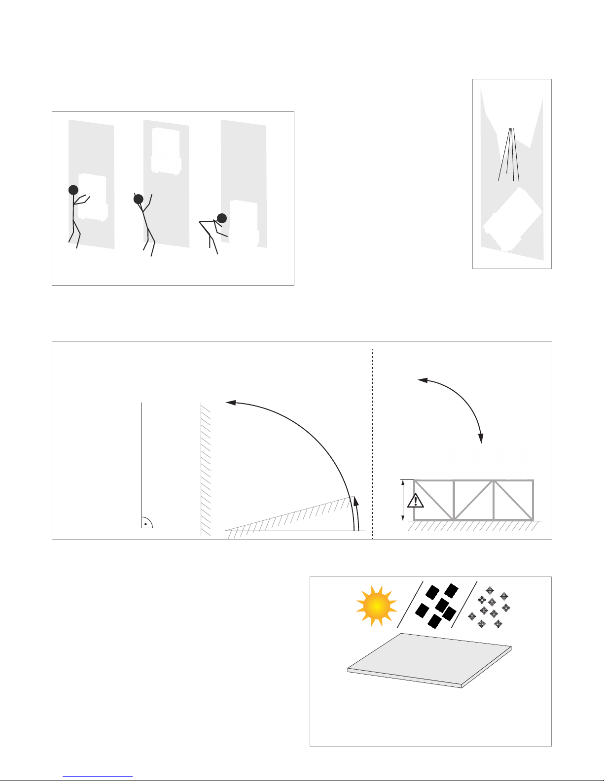
Installation location of the inverter
► Attach the inverter so that the information on the display
can be read and the buttons can be operated without any
problems.
?
?
?
?
✔
✘ ✘
► The inverter is very heavy. The wall
or mounting system must be able
to bear the heavy weight of the
inverter.
► Always use the mounting plate sup-
plied with the inverter.
► Use mounting materials (dowels,
screws etc.) that are suitable for the
wall or the mounting system, as well
as the heavy weight of the inverter.
► Mount the inverter on a vibration-
free wall to avoid disruptions.
► When using the inverter in residen-
tial areas or in buildings with animals, possible noise emissions can
be disturbing. Therefore, carefully
choose the place of installation.
► Mount the inverter on a reproof
wall.
Mounting alignment
Planning the installation
≥15°
≤90°
0° ... 90°
≥ 30 cm
Mounting without mounting rack Mounting with mounting rack

15
Quick Installation Guide for Solar Power Inverter M88H EU V3 EN 5013240202 02 2018-03-22
Planning the installation
► Ensure sufcient air circulation. Hot
air must be able to dissipate upwards.
Leave enough space around each
inverter.
► Do not install inverters above one an-
other so that they do not heat each other.
► Note the Operating temperature range
without derating and the Operating
temperature range. When the Operating temperature range without derating
is exceeded the inverter reduces the AC
power fed into the mains grid. When the
Operating temperature range is exceeded the inverter stops feeding AC power
into the grid. This is normal operating
behavior for the inverter and is necessary
to protect the internal electronics.
► In areas with many trees or elds, pollen
can clog the air inlets and outlets, hinder-
ing the air ow.
Installation clearances and air circulation
Lifting and transporting the inverter
► Screw eyebolts onto the upper side of the inverter. The
screw eyebolts are not included in the scope of delivery.
► Lift the inverter with a block and tackle or crane.
16
Quick Installation Guide for Solar Power Inverter M88H EU V3 EN 5013240202 02 2018-03-22
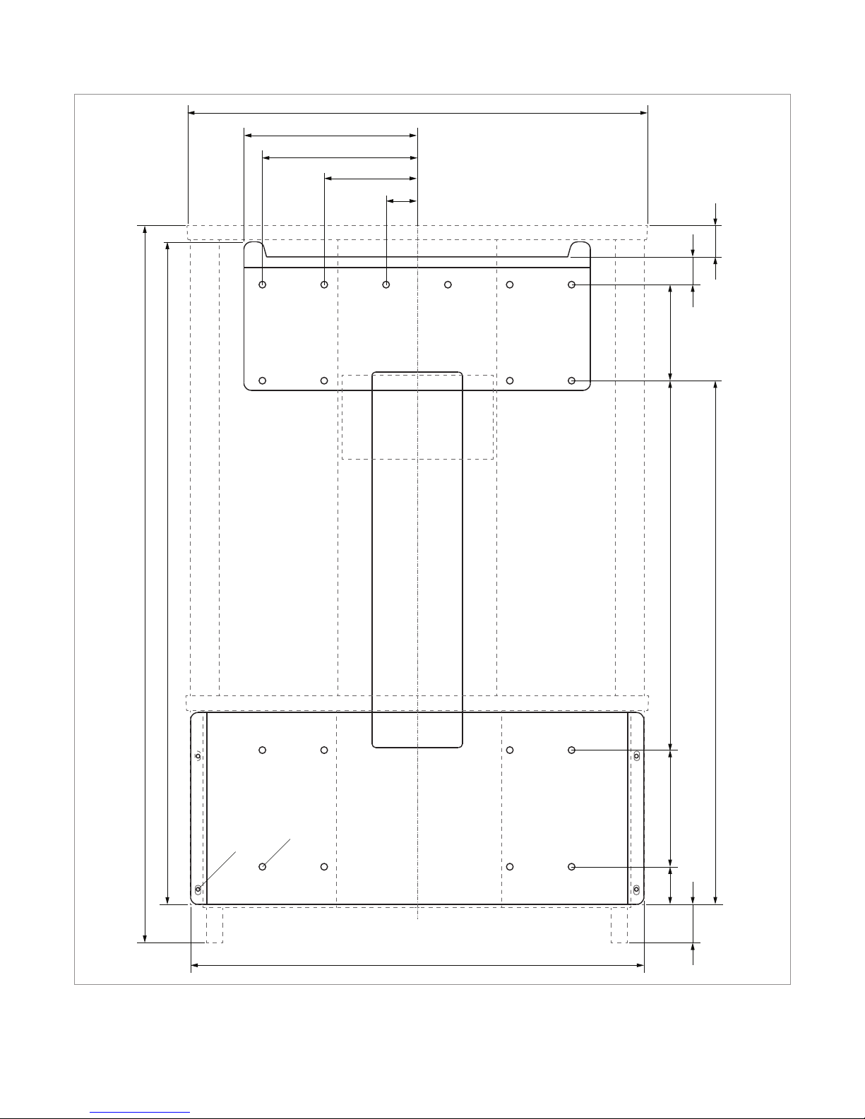
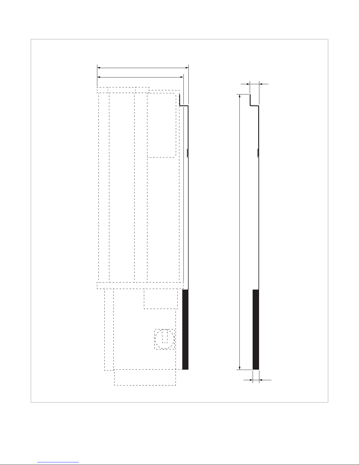
Dimensions
50
155 485 128
37
49
690
602
123
41
205
230
612
960
875
M6
∅8.5
42
17
Quick Installation Guide for Solar Power Inverter M88H EU V3 EN 5013240202 02 2018-03-22
293
275
30
26
875
Dimensions
18
Quick Installation Guide for Solar Power Inverter M88H EU V3 EN 5013240202 02 2018-03-22
AC and DC terminal blocks - general information
The section describes the general technical characteristics of the
AC and DC terminal blocks. The special features which apply to
the installation of the inverter are explained in the following sections.
AC and DC terminal blocks are of the same type.
The specications in this section have been
dened by Phoenix Contact. Check if the technical specications have change before starting
installation work, see www.phoenixcontact.com.
NOTICE
Danger of a cable re.
Bending and twisting causes damage to the
inner structure of the conductor, which leads to
punctiform increase in electrical resistance. This
can result in an overheating of the conductor
and destruction of the insulation.
► When bending and twisting cables or
conductors, always comply with the
manufacturer’s instructions.
AC and DC terminal block specications
Designation Phoenix Contact UKH 150
Connection type Screws with hexagon socket head
Screw thread M10
Rated current I
N
309 A
Rated voltage U
N
1000 V
Attaching the conductor
Type of attachment M10 screws with hexagon socket
head
Tightening torque
25 ... 30 Nm
Specication for copper cable
Min./max. Wire cross-section
Without wire end sleeve
● rigid cable 35 ... 150 mm
2
● exible cable 50 ... 150 mm
2
with wire end sleeve
● Flexible cable (wire end sleeve
without plastic sleeve)
50 ... 150 mm
2
● exible cable (wire end sleeve with
plastic sleeve)
50 ... 150 mm
2
Stripping length 40 mm
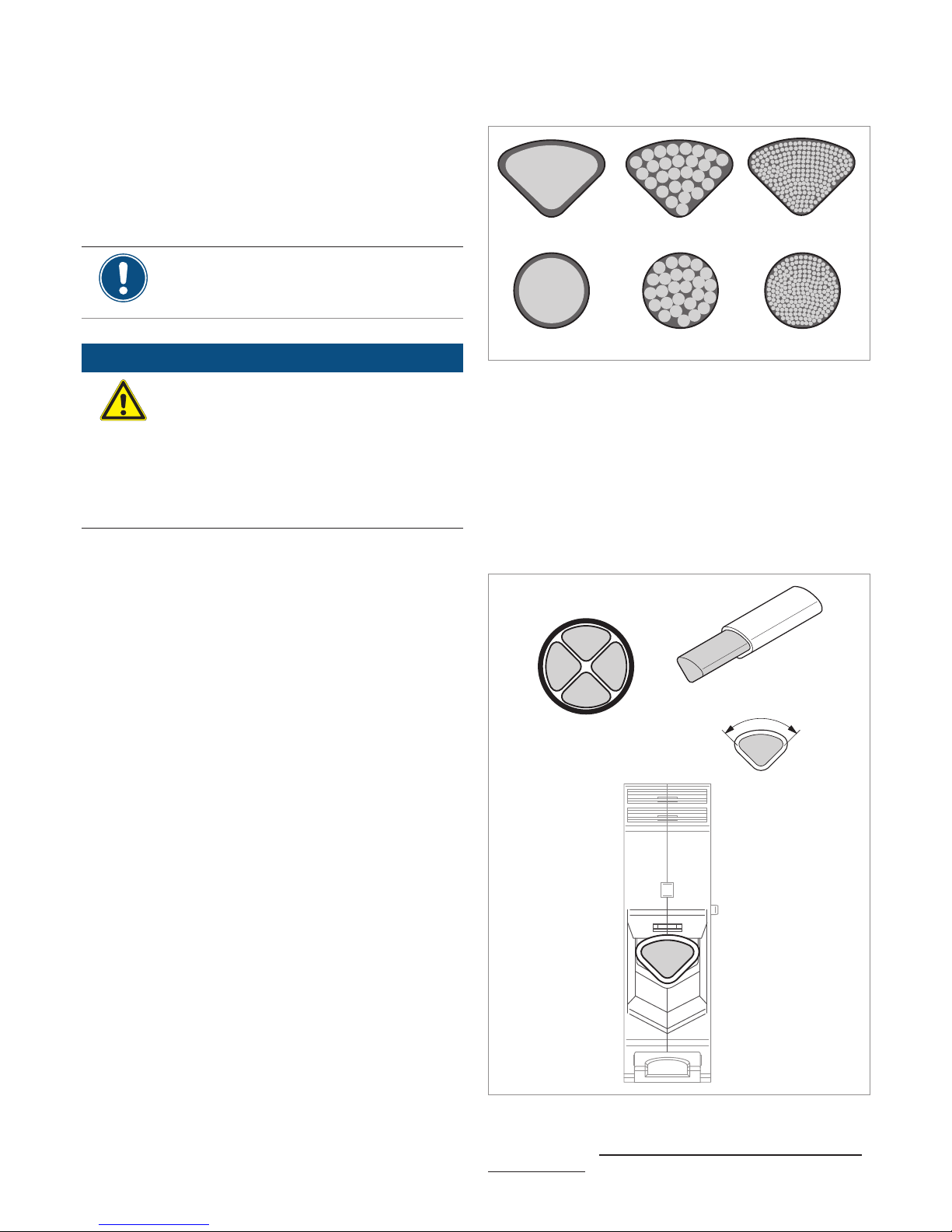
Specication for aluminum cable
SE SM-S SM-L
RE RM-S RM-L
SE sector-shaped, solid conductor
SM-S sector-shaped, multi-conductor, rigid wires
SM-L sector-shaped, multi-conductor, (stranded wires)
RE round, solid conductor
RM-S round, multi-conductor, rigid wires
RM-L round, multi-conductor, (stranded wires)
The terminals have been specially developed for direct connec-
tion of sector-shaped, solid (SE) aluminum cables:
Min./max. Conductor cross-section
120 / 150 mm
2
Stripping length 40 mm
SE
90°
If other types of aluminum cables are used, Al-Cu crimped connectors (such as those from Klauke, Elpress or Mecatraction)
must be used, see “Special instructions for the use of aluminum
cables”, page 22.
AC and DC cable requirements – M88H_121 (ST)
 Loading...