

Page 1

Quick Installation Guide
Solar Inverters
M88H_121 (ST) with Delta part number: RPI883M121300, Product version 0
M88H_122 (CF) with Delta part number: RPI883M122300, Product version 0
EuropeUnited Kingdom
solarsolutions.delta-emea.com
Page 2

This quick installation guide applies to the following inverter models:
● M88H_121 (with DC terminal block, Delta part number
RPI883M121300, product version 0)
● M88H_122 (with DC connections of multi-contact and
string fuses, Delta part number RPI883M122300, product version 0)
with rmware versions:
DSP: 1.42 / RED: 1.03 / COM: 1.21 or higher
The Delta part number can be found on the type plate of the
inverter. The product version is shown by the last letters of the
serial number, which is also located on the type plate. The rmware versions are listed on the display in the Inverter Info.
menu.
The Delta manuals undergo continuous revision in order to
provide you with complete information regarding the installation
and operation of our inverters. Therefore, before starting installation work, always consult solarsolutions.delta-emea.com to
check whether a newer version of the Quick Installation Guide
or of the comprehensive Installation and Operation Manual is
available.
© Copyright – Delta Electronics (Netherlands) B.V. – All rights
reserved.
This manual is intended for installers.
The information in this manual is to be treated as condential and
no part of this manual may be reproduced without prior written
permission from Delta Electronics. The information in this manual
may not be used for any purpose not directly connected to the
use of the inverter.
All information and specications can be modied without prior
notice.
All translations of this manual that are not authorized by Delta
Electronics (Netherlands) B.V. must be marked with the words
"Translation of the original operating instructions."
Delta Electronics (Netherlands) B.V.
Tscheulinstraße 21
79331 Teningen
Germany
Authorized representative for this product in the EU:
Delta Electronics (Netherlands) B.V.
Zandsteen 15
2132 MZ Hoofddorp
Netherlands
2
Quick installation guide for solar inverter M88H RPI883M121300 RPI883M122300 EU V1 EN 5017414200_00 2019-11-07
Page 3

Table of contents
Basic safety instructions. . . . . . . . . . . . . . . . . . . . . . . . . . . . . . . . . . . . . . . . . . . . . . . . . . . . . . . . .4
Scope of delivery . . . . . . . . . . . . . . . . . . . . . . . . . . . . . . . . . . . . . . . . . . . . . . . . . . . . . . . . . . . . . 6
M88H_121 (ST) . . . . . . . . . . . . . . . . . . . . . . . . . . . . . . . . . . . . . . . . . . . . . . . . . . . . . . . . . . . . 6
M88H_122 (CF) . . . . . . . . . . . . . . . . . . . . . . . . . . . . . . . . . . . . . . . . . . . . . . . . . . . . . . . . . . . . 7
Components of the inverter . . . . . . . . . . . . . . . . . . . . . . . . . . . . . . . . . . . . . . . . . . . . . . . . . . . . . . . 8
M88H_121 (ST) . . . . . . . . . . . . . . . . . . . . . . . . . . . . . . . . . . . . . . . . . . . . . . . . . . . . . . . . . . . . 8
M88H_122 (CF) . . . . . . . . . . . . . . . . . . . . . . . . . . . . . . . . . . . . . . . . . . . . . . . . . . . . . . . . . . . 10
Display, buttons, and LEDs / Type plate. . . . . . . . . . . . . . . . . . . . . . . . . . . . . . . . . . . . . . . . . . . . . . . . 12
Hazard zones in the wiring box . . . . . . . . . . . . . . . . . . . . . . . . . . . . . . . . . . . . . . . . . . . . . . . . . . . . 13
Planning the installation . . . . . . . . . . . . . . . . . . . . . . . . . . . . . . . . . . . . . . . . . . . . . . . . . . . . . . . . 14
Dimensions . . . . . . . . . . . . . . . . . . . . . . . . . . . . . . . . . . . . . . . . . . . . . . . . . . . . . . . . . . . . . . . 16
AC and DC cable requirements . . . . . . . . . . . . . . . . . . . . . . . . . . . . . . . . . . . . . . . . . . . . . . . . . . . . 18
M88H_121 (ST) – AC and DC terminal blocks . . . . . . . . . . . . . . . . . . . . . . . . . . . . . . . . . . . . . . . . . . . . 18
M88H_121 (ST) – AC and DC cable . . . . . . . . . . . . . . . . . . . . . . . . . . . . . . . . . . . . . . . . . . . . . . . . . 19
M88H_122 (CF) – AC Cable . . . . . . . . . . . . . . . . . . . . . . . . . . . . . . . . . . . . . . . . . . . . . . . . . . . . . 20
M88H_122 (CF) – DC cable . . . . . . . . . . . . . . . . . . . . . . . . . . . . . . . . . . . . . . . . . . . . . . . . . . . . . 21
Special instructions for the use of aluminum cables . . . . . . . . . . . . . . . . . . . . . . . . . . . . . . . . . . . . . . . . 22
Communications cable requirements . . . . . . . . . . . . . . . . . . . . . . . . . . . . . . . . . . . . . . . . . . . . . . . . . 24
Routing the cables . . . . . . . . . . . . . . . . . . . . . . . . . . . . . . . . . . . . . . . . . . . . . . . . . . . . . . . . . . . 25
Mounting the inverter. . . . . . . . . . . . . . . . . . . . . . . . . . . . . . . . . . . . . . . . . . . . . . . . . . . . . . . . . . 26
Grounding the inverter housing . . . . . . . . . . . . . . . . . . . . . . . . . . . . . . . . . . . . . . . . . . . . . . . . . . . . 29
Connecting to the grid (AC) . . . . . . . . . . . . . . . . . . . . . . . . . . . . . . . . . . . . . . . . . . . . . . . . . . . . . . 30
General notes . . . . . . . . . . . . . . . . . . . . . . . . . . . . . . . . . . . . . . . . . . . . . . . . . . . . . . . . . . . . 30
M88H_121 (ST) – Cable gland . . . . . . . . . . . . . . . . . . . . . . . . . . . . . . . . . . . . . . . . . . . . . . . . . . . . 32
M88H_121 (ST) – Tips . . . . . . . . . . . . . . . . . . . . . . . . . . . . . . . . . . . . . . . . . . . . . . . . . . . . . . . . 34
M88H_122 (CF) – Cable gland. . . . . . . . . . . . . . . . . . . . . . . . . . . . . . . . . . . . . . . . . . . . . . . . . . . . 35
M88H_122 (CF) – Tips . . . . . . . . . . . . . . . . . . . . . . . . . . . . . . . . . . . . . . . . . . . . . . . . . . . . . . . 37
Connecting to the solar modules (DC) . . . . . . . . . . . . . . . . . . . . . . . . . . . . . . . . . . . . . . . . . . . . . . . . 38
M88H_121 (ST) – Cable gland . . . . . . . . . . . . . . . . . . . . . . . . . . . . . . . . . . . . . . . . . . . . . . . . . . . . 38
M88H_121 (ST) – 1-/2-MPP Tracker operation . . . . . . . . . . . . . . . . . . . . . . . . . . . . . . . . . . . . . . . . . . . 39
M88H_122 (CF) . . . . . . . . . . . . . . . . . . . . . . . . . . . . . . . . . . . . . . . . . . . . . . . . . . . . . . . . . . . 41
Correctly closing the terminal box . . . . . . . . . . . . . . . . . . . . . . . . . . . . . . . . . . . . . . . . . . . . . . . . . . 44
Connecting the communication card . . . . . . . . . . . . . . . . . . . . . . . . . . . . . . . . . . . . . . . . . . . . . . . . . 45
Overview . . . . . . . . . . . . . . . . . . . . . . . . . . . . . . . . . . . . . . . . . . . . . . . . . . . . . . . . . . . . . . . 45
Connecting a data logger via RS485 . . . . . . . . . . . . . . . . . . . . . . . . . . . . . . . . . . . . . . . . . . . . . . . . . 46
Connecting the digital inputs, dry contacts and external power-off (optional) . . . . . . . . . . . . . . . . . . . . . . . . . . . . 47
Attaching warning labels to the inverter . . . . . . . . . . . . . . . . . . . . . . . . . . . . . . . . . . . . . . . . . . . . . . . 48
Commissioning – Basic settings . . . . . . . . . . . . . . . . . . . . . . . . . . . . . . . . . . . . . . . . . . . . . . . . . . . 49
Commissioning – Further settings (optional). . . . . . . . . . . . . . . . . . . . . . . . . . . . . . . . . . . . . . . . . . . . . 50
Date and time . . . . . . . . . . . . . . . . . . . . . . . . . . . . . . . . . . . . . . . . . . . . . . . . . . . . . . . . . . . . 50
Inverter ID . . . . . . . . . . . . . . . . . . . . . . . . . . . . . . . . . . . . . . . . . . . . . . . . . . . . . . . . . . . . . . 50
Baud rate for RS485 . . . . . . . . . . . . . . . . . . . . . . . . . . . . . . . . . . . . . . . . . . . . . . . . . . . . . . . . . 51
AC connection type. . . . . . . . . . . . . . . . . . . . . . . . . . . . . . . . . . . . . . . . . . . . . . . . . . . . . . . . . . 51
External shutdown (E-Power off, EPO). . . . . . . . . . . . . . . . . . . . . . . . . . . . . . . . . . . . . . . . . . . . . . . . 52
Active power limitation . . . . . . . . . . . . . . . . . . . . . . . . . . . . . . . . . . . . . . . . . . . . . . . . . . . . . . . . 52
Dry contacts (relays) . . . . . . . . . . . . . . . . . . . . . . . . . . . . . . . . . . . . . . . . . . . . . . . . . . . . . . . . . 53
Technical data. . . . . . . . . . . . . . . . . . . . . . . . . . . . . . . . . . . . . . . . . . . . . . . . . . . . . . . . . . . . . . 54
M88H_121 (ST) . . . . . . . . . . . . . . . . . . . . . . . . . . . . . . . . . . . . . . . . . . . . . . . . . . . . . . . . . . . 54
M88H_122 (CF) . . . . . . . . . . . . . . . . . . . . . . . . . . . . . . . . . . . . . . . . . . . . . . . . . . . . . . . . . . . 56
Customer Service - Europe . . . . . . . . . . . . . . . . . . . . . . . . . . . . . . . . . . . . . . . . . . . . . . . . . . . . . . 60
Quick installation guide for solar inverter M88H RPI883M121300 RPI883M122300 EU V1 EN 5017414200_00 2019-11-07
3
Page 4
Basic safety instructions
Safety instructions for all M88H
WARNING
Electric shock
When the cover is removed from the wiring box,
this exposes voltage-carrying parts and protection conforming to IP65 is no longer guaranteed.
► Remove the cover only when absolutely
necessary.
► Do not remove the cover if water or dirt
might enter the inverter.
► After work is completed, ensure that the
cover is properly replaced and screwed in.
Check that the cover is properly sealed.
NOTICE
Incorrectly dimensioned solar system.
A solar system of the wrong size may cause
damage to the inverter.
► When calculating the module string, always
pay attention to technical data of the inverter
(input voltage range, maximum current
and maximum input power); see chapter
"Technical Data."
● To comply with the IEC 62109-5.3.3 safety requirements
and avoid injury or material damage, the inverter must be
installed and operated in accordance with the safety and
operating instructions set out in this manual. Delta Electronics is not responsible for damage resulting from failure to
follow the safety and operating instructions set out in this
manual.
● The inverter may be installed and commissioned only by
installers who have been trained and certied for the installation and operation of mains-based solar inverters.
● All repair work on the inverter must be carried out by Delta
Electronics. Otherwise, the warranty will be void.
● Warning instructions and warning symbols attached to the
inverter by Delta Electronics must not be removed.
● The inverter has a high leakage current value. The groun-
ding cable must be connected before commencing operation.
● Do not disconnect any cables while the inverter is under
load due to risk of a fault arc.
● To prevent damage due to lightning strikes, follow the provi-
sions that apply in your country.
● The surface of the inverter can get very hot during operati-
on. Wear safety gloves when you touch the inverter (apart
from at the display).
● The inverter is very heavy. For lifting and moving use a me-
chanical lifting device (e.g. a crane or hoist). At least three
persons are required for manual hoisting and moving.
● Only equipment in accordance with SELV (EN 60950) may
be connected to the RS485 interfaces.
● All connections must be sufciently insulated in order to
ensure the IP65 degree of protection. Unused connections
must be closed using cover caps.
Safety instructions for the M88H_121 (ST)
DANGER
Electric shock
Potentially fatal voltages are present at the
inverter during operation. When the inverter
is disconnected from all power sources, this
voltage remains in the inverter for up to 100
seconds.
Therefore, always carry out the following steps
before working on the inverter:
1. Disconnect the inverter from all AC and DC
voltage sources and make sure that none
of the connections can be accidentally
restored.
2. Wait at least 100 seconds until the internal
capacitors have discharged.
DANGER
Electric shock
Potentially fatal voltages are present at the
inverter DC connections. When light falls on the
solar modules, they immediately start to generate electricity. This also happens when light does
not fall directly on the solar modules.
► Never disconnect the inverter from the solar
modules when it is under load.
► Disconnect the connection to the mains so
that the inverter cannot supply energy to the
mains.
► Disconnect the inverter from all AC and DC
voltage sources. Ensure that none of the
connections can be restored accidentally.
► Ensure that the DC cables cannot be
touched accidentally.
4
Quick installation guide for solar inverter M88H RPI883M121300 RPI883M122300 EU V1 EN 5017414200_00 2019-11-07
Page 5
Safety instructions for the M88H_122 (CF)
DANGER
Electric shock
Potentially fatal voltages are present at the
inverter during operation. When the inverter
is disconnected from all power sources, this
voltage remains in the inverter for up to 100
seconds.
Therefore, always carry out the following steps
before working on the inverter
1. Turn the DC isolating switch to the 0 (OFF)
position.
2. Disconnect the inverter from all AC and DC
voltage sources and make sure that none
of the connections can be accidentally
restored.
3. Wait at least 100 seconds until the internal
capacitors have discharged.
Basic safety instructions
DANGER
Electric shock
Potentially fatal voltages are present at the
inverter DC connections. When light falls on the
solar modules, they immediately start to generate electricity. This also happens when light does
not fall directly on the solar modules.
► Never disconnect the inverter from the solar
modules when it is under load.
► Turn the DC isolating switch to the 0 (OFF)
position.
► Disconnect the connection to the mains so
that the inverter cannot supply energy to the
mains.
► Disconnect the inverter from all AC and DC
voltage sources. Ensure that none of the
connections can be restored accidentally.
► Ensure that the DC cables cannot be
touched accidentally.
Quick installation guide for solar inverter M88H RPI883M121300 RPI883M122300 EU V1 EN 5017414200_00 2019-11-07
5
Page 6
Scope of delivery
M88H_121 (ST)
Part Description Part Description
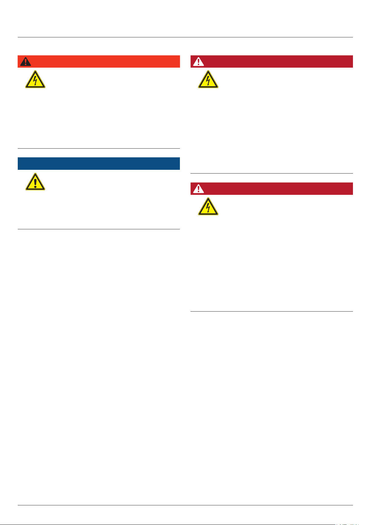
M88H_121 inverter
with wiring box
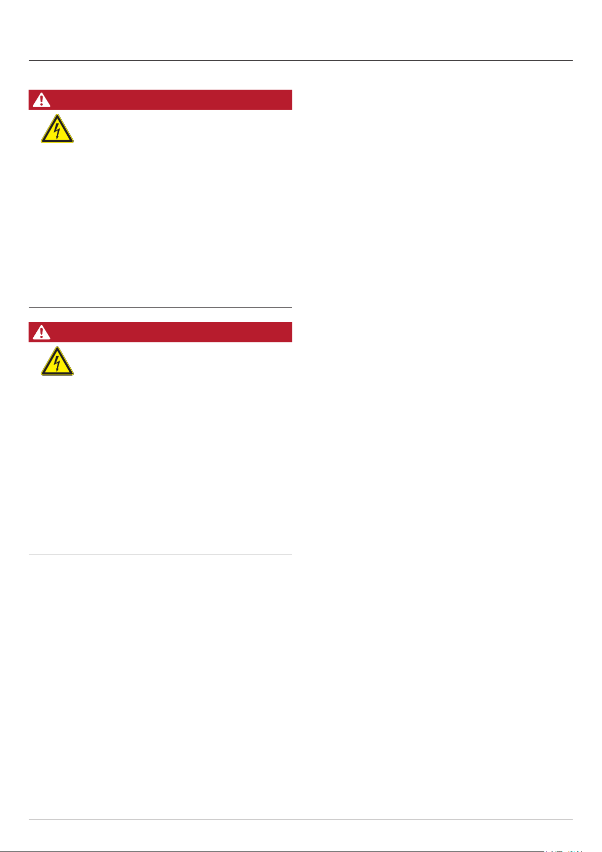
Cover caps
Cable gland for AC
feed-through
1
Mounting plate 1
For closing the upper cable feed-throughs on the wiring box when the power module is removed from
the wiring box. The cover caps are tted to the mounting plate.
2
1
For feeding the AC cable into the
wiring box.
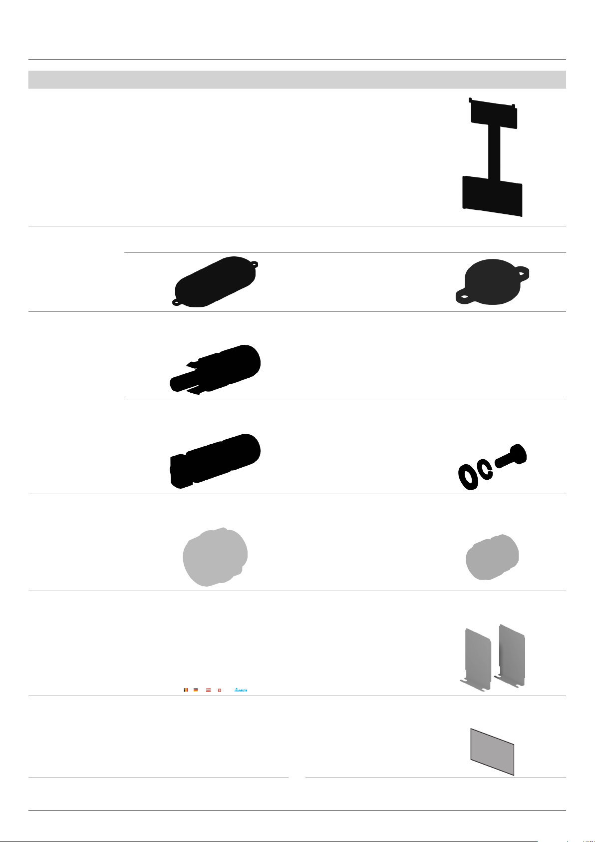
For grounding the inverter
1
M6 grounding material 1
housing; contains M6 nut, spring
washer and washer; mounted on
the inverter.
For feeding the DC cable into the
wiring box.
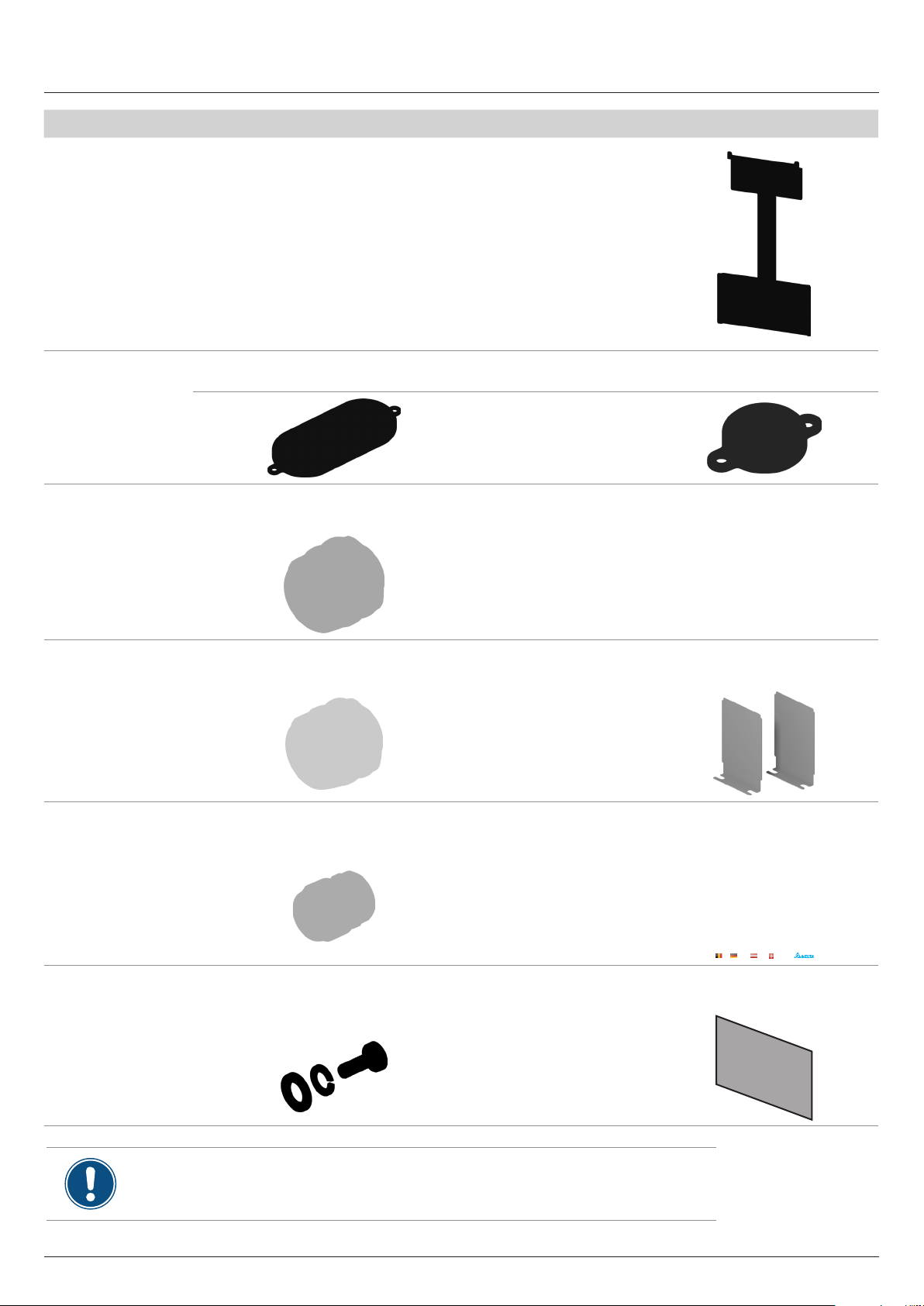
For covering the air inlets and preventing the entry of small animals.
Cable gland for DC
feed-through
Cable gland for the
communication connection
M6 mounting screw 5
Check the delivery for completeness and all components for damage before starting installation work.
Do not use any damaged components.
Keep the packaging.
2
For fastening the communication
cables to the wiring box.
1
For fastening the wiring box to the
mounting plate; with spring washer
and washer.
Screening plate for the
air inlet
Quick installation
guide and basic safety
instructions
Display cover 1
2
1
Installationskurzanleitung
Solar-Wechselrichter M88H_121 (ST) und M88H_122 (CF, Produktversion D)
Deutschland Österreich SchweizBelgien
To protect the display against
damage
6
Quick installation guide for solar inverter M88H RPI883M121300 RPI883M122300 EU V1 EN 5017414200_00 2019-11-07
Page 7
Scope of delivery
Part Description Part Description
M88H_122 (CF)
M88H_122 inverter
with wiring box
Cover caps
DC plug
1
Mounting plate 1
For closing the upper cable feed-throughs on the wiring box when the inverter part is disconnected.
The cover caps are tted to the mounting plate.
2
1
Multi-Contact MC4 plug for DC +
2
(32.0017P0001-UR for 4/6 mm
18
)
M6 grounding material 1
For grounding the inverter
housing; contains M6 nut, spring
washer and washer; mounted on
the inverter.
Multi-Contact MC4 plug for DC–
(32.0016P0001-UR for 4/6 mm
2
)
For fastening the wiring box to the
mounting plate; with spring washer
and washer
Cable gland for the
AC connection
Quick installation
guide and basic
safety instructions
18
For feeding the AC cable into the
wiring box
1
1
Installationskurzanleitung
Solar-Wechselrichter M88H_121 (ST) und M88H_122 (CF, Produktversion D)
Deutschland Österreich SchweizBelgien
M6 mounting screw 5
Cable gland for the
communication connection
Screening plate for the
air inlet
For fastening the communication
cable to the wiring box
1
For covering the air inlets and preventing the entry of small animals.
2
To protect the display against
damage
Display cover 1
Quick installation guide for solar inverter M88H RPI883M121300 RPI883M122300 EU V1 EN 5017414200_00 2019-11-07
7
Page 8
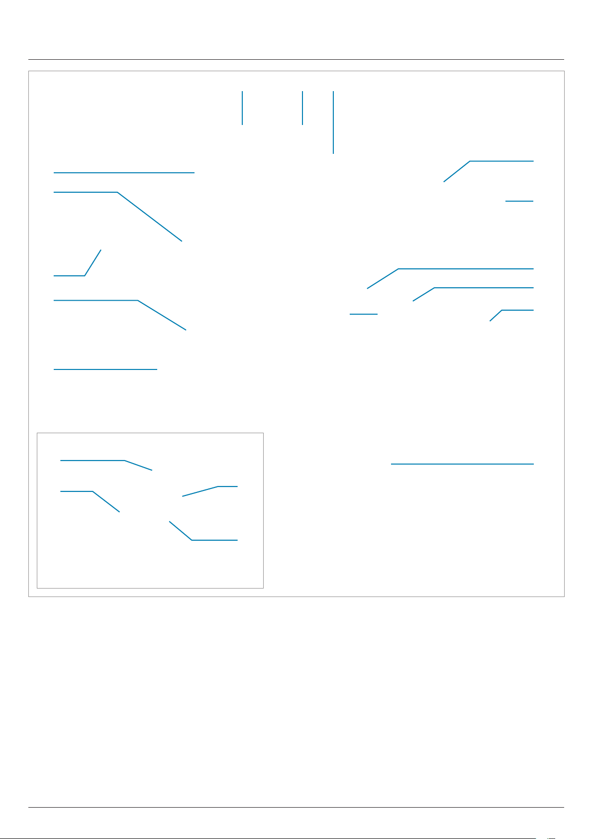
Components of the inverter
M88H_121 (ST)
13
6.2
12
11
10
4.2
1 2
3
4.1
5
6.1
8
7
11
11.4
11.3
1 Power module 8 Grounding connection
2 Display, buttons, and LED 9 Mounting plate
3 Fan module 10 Cable gland for the communication connection
4 Filter for air outlet (2x) 11 Communication card
5 Filter for air inlet 12 AC cable gland
6 Cover panel for the air inlet (2x) 13 Cover panel for the wiring box
7 DC cable gland (2x)
11.1 RS485 connection
11.2 Digital inputs
11.3 Dry contacts
11.4 DIP switch for VCC and RS485 termination resistor
11.1
11.2
9
8
Quick installation guide for solar inverter M88H RPI883M121300 RPI883M122300 EU V1 EN 5017414200_00 2019-11-07
Page 9
DANGER
Modied design of the DC connections
The design of the DC connections on the DC
terminal block has changed in comparison with
previous versions of the M88H_121 (ST)!
► You must comply with the correct use of plus
Components of the inverter
M88H_121 (ST)
(+) and minus (-) when connecting the DC
cables.
14
16
14 Type-2 DC surge protection devices 16 Type-2 AC surge protection devices
15 DC terminal block 17 AC terminal block
1517
Quick installation guide for solar inverter M88H RPI883M121300 RPI883M122300 EU V1 EN 5017414200_00 2019-11-07
9
Page 10
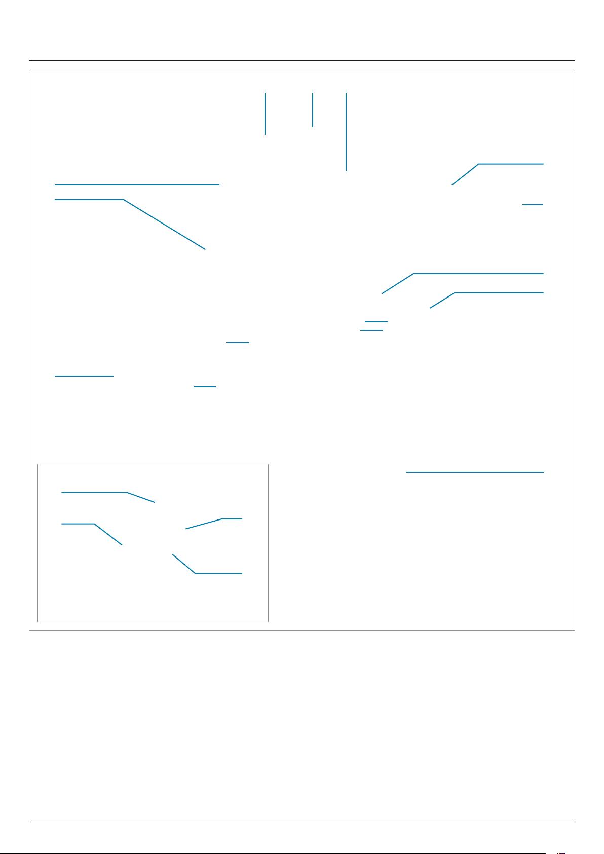
Components of the inverter
M88H_122 (CF)
13
6.2
12
11
10
4.2
1 2
3
4.1
5
6.1
7
8
10
10.4
10.3
1 Power module 8 DC Disconnection switch
2 Display, buttons, and LED 9 Mounting plate
3 Fan module 10 Communication card
4 Filter for air outlet (2x) 11 Cable gland for the communication connection
5 Filter for air inlet 12 AC cable gland
6 Cover panel for the side air inlet (2x) 13 Cover panel for the wiring box
7 Grounding connection
10.1 RS485 connection
10.2 Digital inputs
10.3 Dry contacts
10.4 DIP switch for VCC and RS485 termination resistor
10.1
10.2
9
10
Quick installation guide for solar inverter M88H RPI883M121300 RPI883M122300 EU V1 EN 5017414200_00 2019-11-07
Page 11
Components of the inverter
M88H_122 (CF)
18
14
15
1617
14 Type-2 AC surge protection devices 16 DC1 string fuses 18 AC terminal block
15 Type-2 DC surge protection devices 17 DC2 string fuses
Quick installation guide for solar inverter M88H RPI883M121300 RPI883M122300 EU V1 EN 5017414200_00 2019-11-07
11
Page 12
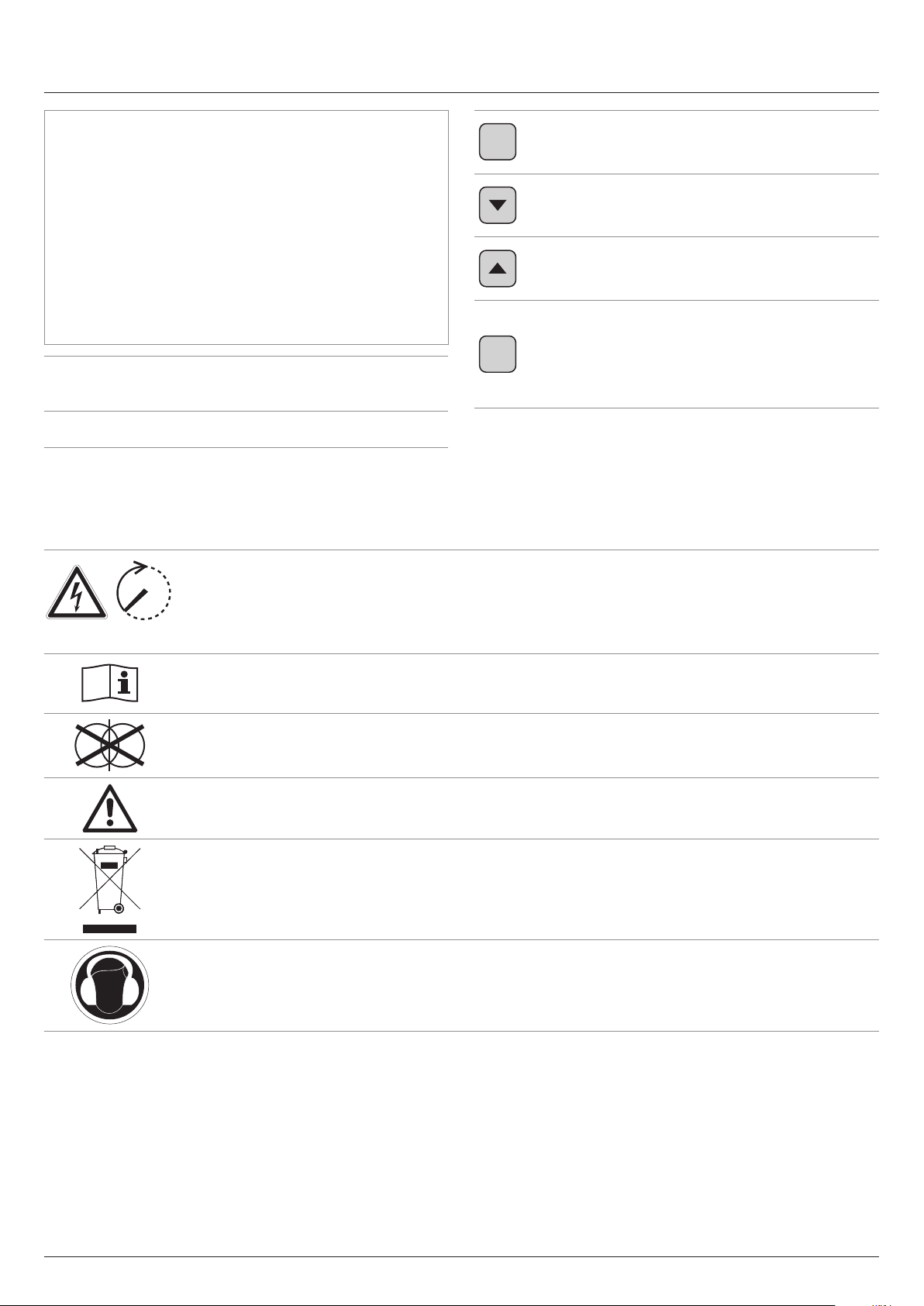
Display, buttons, and LEDs / Type plate
Green LED Lights up when the
Grid Grid
AlArm Alarm
inverter is supplying electricity to the
mains grid.
Red LED Indicates an error, a failure
or a warning.
EXIT
ENT
EXIT
Down
Up
ENTER
Exit the current menu.
Cancel the setting for a parameter.
Changes are not applied.
Move downwards in the menu.
Reduce the value of a congurable
parameter.
Move upwards in the menu.
Increase the value of a congurable
parameter.
Select menu item.
Open a congurable parameter for
editing.
Cancel the setting for a parameter.
Changes are adopted.
100 seconds
Danger to life through electric shock
Potentially fatal voltage is present inside the inverter during operation and this voltage remains present for up
to 100 seconds after disconnection from the power supply.
Only the wiring box may be opened. All other device parts may not be opened.
Before working on the inverter, read the supplied manual and follow the instructions contained therein.
This inverter is not separated from the grid by a transformer.
The housing of the inverter must be grounded if this is required by local regulations.
WEEE mark
The inverter must not be disposed of as standard household waste, but in accordance with the applicable
electronic waste disposal regulations of your country or region.
This regulatory symbol does not apply to the EU because the noise level lies below the EU guidelines.
12
Quick installation guide for solar inverter M88H RPI883M121300 RPI883M122300 EU V1 EN 5017414200_00 2019-11-07
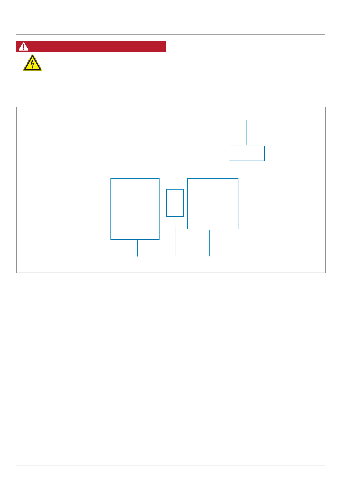
Page 13
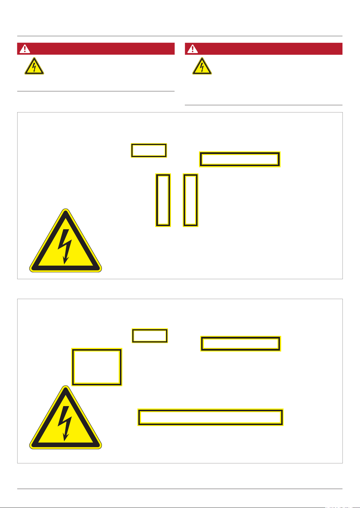
Hazard zones in the wiring box
DANGER
Electric shock
The cover in the interior of the wiring box does
not have to be removed for cabling work.
All connections are accessible, even when the
internal cover is installed.
DANGER
Modied design of the DC inputs
The design of the DC inputs on the DC terminal
block has changed in comparison with previous
versions of the M88H_121 (ST)!
► You must comply with the correct use of plus
(+) and minus (-) when connecting the DC
cables.
Hazard zones with potentially life-threatening currents and voltages – M88H_121 (ST)
Hazard zones with potentially life-threatening currents and voltages – M88H_122 (CF)
Quick installation guide for solar inverter M88H RPI883M121300 RPI883M122300 EU V1 EN 5017414200_00 2019-11-07
13
Page 14
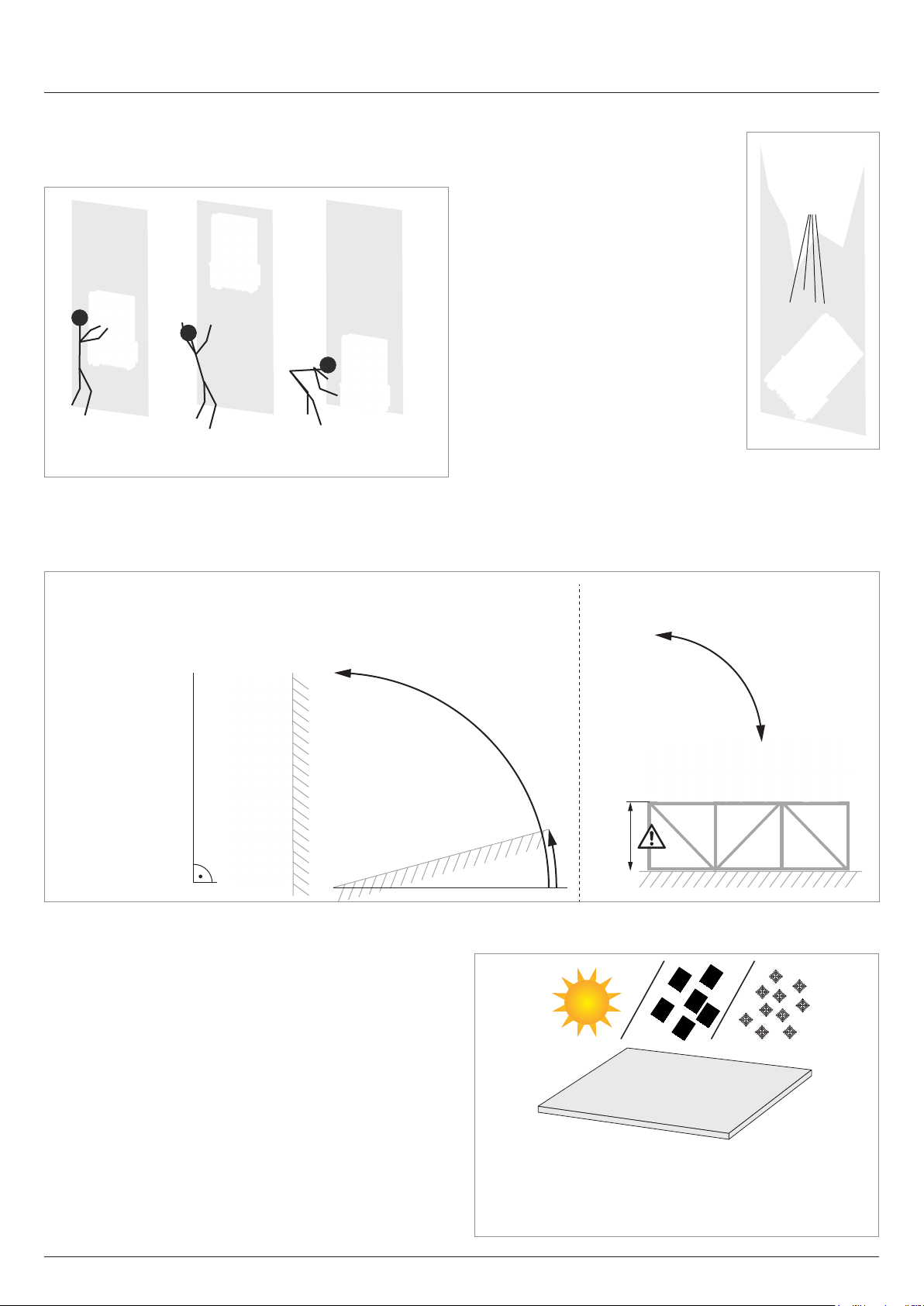
Planning the installation
Installation location of the inverter
► Attach the inverter so that the information on the display
can be read and the buttons can be operated without any
problems.
?
?
?
?
✔
✘ ✘
► The inverter is very heavy. The wall
or mounting system must be able
to bear the heavy weight of the
inverter.
► Always use the mounting plate
supplied with the inverter.
► Use mounting materials (dowels,
screws etc.) that are suitable for the
wall or the mounting system, as well
as the heavy weight of the inverter.
► Mount the inverter on a vibration-
free wall to avoid disruptions.
► When using the inverter in residenti-
al areas or in buildings with animals, possible noise emissions can
be disturbing. Therefore, carefully
choose the place of installation.
► Mount the inverter on a reproof
wall.
Mounting alignment
Mounting without mounting rack Mounting with mounting rack
≤90°
Outdoor installations
► The inverter has a protection degree of IP65 and can be
installed indoors and outdoors. Despite this, the inverter
should be protected by a roof against direct solar irradiation, rain and snow. For example, the power of the inverter
will be reduced if it is too heavily heated by solar radiation.
This is normal operating behavior for the inverter and is
necessary to protect the internal electronics.
0° ... 90°
≥ 30 cm
≥15°
14
Quick installation guide for solar inverter M88H RPI883M121300 RPI883M122300 EU V1 EN 5017414200_00 2019-11-07
Page 15
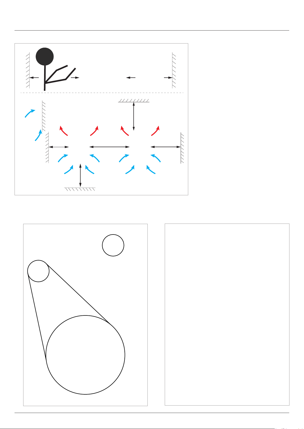
Installation clearances and air circulation
>40 cm
>80 cm
>60 cm
>60 cm
>60 cm
Planning the installation
► Ensure sufcient air circulation. Hot air
must be able to dissipate upwards. Leave enough space around each inverter.
► Do not install inverters above one ano-
ther so that they do not heat each other.
► Note the Operating temperature ran-
ge without derating and the Operating
temperature range. When the Operating
temperature range without derating is
exceeded, the inverter reduces the AC
power fed into the mains grid. When the
Operating temperature range is exceeded, the inverter stops feeding AC power
into the mains. This is normal operating
behavior for the inverter and is necessary
to protect the internal electronics.
► In areas with many trees or elds, pollen
can clog the air inlets and outlets, hinde-
ring the air ow.
>50 cm
Lifting and transporting the inverter
► Screw the eyebolts onto the top side of the inverter. The
screw eyebolts are not included in the scope of delivery.
► Lift the inverter using a block and tackle or crane.
Quick installation guide for solar inverter M88H RPI883M121300 RPI883M122300 EU V1 EN 5017414200_00 2019-11-07
15
Page 16
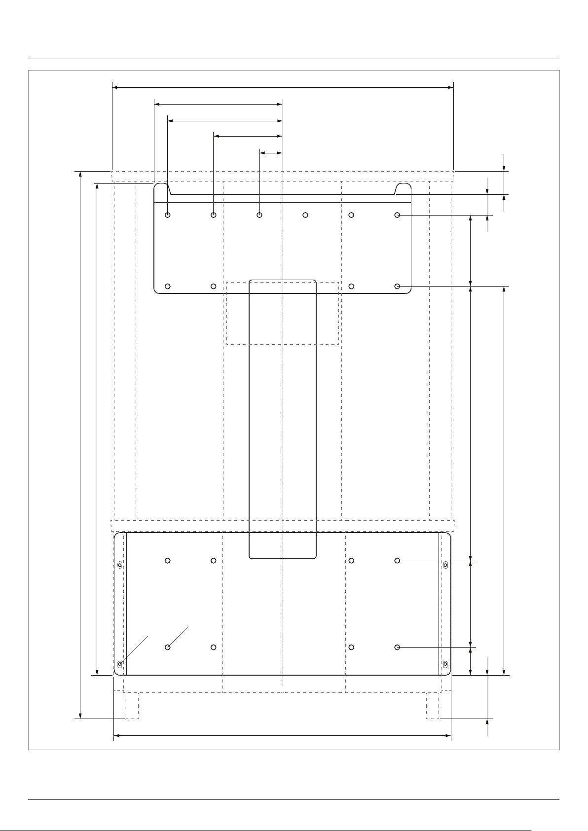
Dimensions
612
230
205
123
41
37
42
986
875
M6
690
155 485 128
∅8.5
50
75
602
16
Quick installation guide for solar inverter M88H RPI883M121300 RPI883M122300 EU V1 EN 5017414200_00 2019-11-07
Page 17
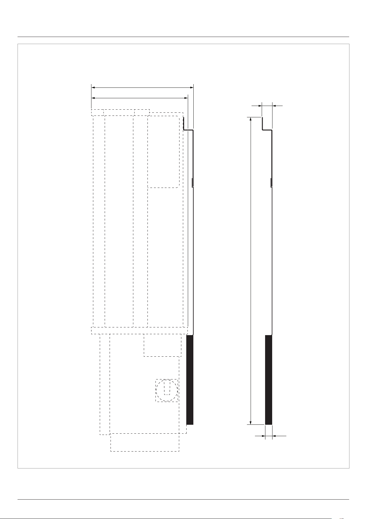
293
275
Dimensions
30
875
26
Quick installation guide for solar inverter M88H RPI883M121300 RPI883M122300 EU V1 EN 5017414200_00 2019-11-07
17
Page 18
AC and DC cable requirements
M88H_121 (ST) – AC and DC terminal blocks
General information
The section describes the general technical characteristics of
the AC and DC terminal blocks. The special features which
apply to the installation of the inverter are explained in the following sections.
AC and DC terminal blocks are of the same type.
The specications in this section have been
dened by Phoenix Contact. Check if the technical specications have changed before starting
installation work; see www.phoenixcontact.com.
NOTICE
Danger of a cable re.
Bending and twisting causes damage to the
inner structure of the conductor, which leads to
punctiform increase in electrical resistance. This
can result in an overheating of the conductor
and destruction of the insulation.
► When bending and twisting cables or
conductors, always comply with the
manufacturer’s instructions.
AC and DC terminal block specications
Naming Phoenix Contact UKH 150
Connection type Screws with hexagon socket head
Screw thread M10
Rated current I
Rated voltage U
N
N
Attaching the conductor
Type of attachment M10 screws with hexagon socket
Tightening torque 25 ... 30 Nm
Specication for copper cable
Min./max. Wire cross-section
Without wire end sleeve
● Rigid cable 35 ... 150 mm
● Flexible cable 50 ... 150 mm
with wire end sleeve
● Flexible cable (wire end sleeve
without plastic sleeve)
● Flexible cable (wire end sleeve with
plastic sleeve)
Stripping length 40 mm
309 A
1000 V
head
50 ... 150 mm
50 ... 150 mm
2
2
2
2
Specication for aluminum cable
SE SM-S SM-L
RE RM-S RM-L
SE sector-shaped, solid conductor
SM-S sector-shaped, multi-conductor, rigid wires
SM-L sector-shaped, multi-conductor, (stranded wires)
RE round, solid conductor
RM-S round, multi-conductor, rigid wires
RM-L round, multi-conductor, (stranded wires)
The terminals have been specially developed for direct connection of sector-shaped, solid (SE) aluminum cables:
Min./max. Conductor cross-section 120 / 150 mm
Stripping length 40 mm
90°
SE
2
18
If other types of aluminum cables are to be used, Al-Cu compression joints (e.g. fromKlauke, Elpress or Mecatraction) must
be used; see „Special instructions for the use of aluminum
cables“, page 22.
Quick installation guide for solar inverter M88H RPI883M121300 RPI883M122300 EU V1 EN 5017414200_00 2019-11-07
Page 19

AC and DC cable requirements
M88H_121 (ST) – AC and DC cable
AC cable
AC cable gland
The inverter has 1 AC cable gland with 1 cable feed-through.
Min./max. Cable diameter 23.9 ... 65.9 mm
Notes on calculating the cable cross-section
Consider the following factors when calculating the cable crosssection:
● Cable material
● Temperature conditions
● Cable length
● Installation type
● Voltage drop
● Loss of power in the cable
DC cables
DC cable gland
The inverter has 2 DC cable glands with 2 cable feed-throughs
each.
Min./max. Cable diameter 12.4 ... 25.7 mm
Instructions for the use of aluminum cables
See „Special instructions for the use of aluminum cables“,
page 22.
Always follow the installation regulations for AC cables applicable in your country.
France: Follow the installation instructions of UTE 15-712-1.
This standard contains requirements for minimum cable crosssections and to prevent overheating due to high currents.
Germany: Follow the installation instructions of VDE 0100-712.
This standard contains requirements for minimum cable crosssections and to prevent overheating due to high currents.
Quick installation guide for solar inverter M88H RPI883M121300 RPI883M122300 EU V1 EN 5017414200_00 2019-11-07
19
Page 20

AC and DC cable requirements
M88H_122 (CF) – AC Cable
AC cable
General information on the AC terminal block
The section describes the general technical characteristics of
the AC terminal blocks. The special features which apply to the
installation of the inverter are explained in the following sections.
The specications in this section have been
dened by Phoenix Contact. Check if the technical specications have changed before starting
installation work; see www.phoenixcontact.com.
NOTICE
Danger of a cable re.
Bending and twisting causes damage to the
inner structure of the conductor, which leads to
punctiform increase in electrical resistance. This
can result in an overheating of the conductor
and destruction of the insulation.
► When bending and twisting cables or
conductors, always comply with the
manufacturer’s instructions.
AC terminal block specications
Naming Phoenix Contact UKH 70
Connection type Screws with hexagon socket head
Screw thread M8
Rated current I
Rated voltage U
N
N
Attaching the conductor
Type of attachment M8 screws with hexagon socket
Tightening torque 8 ... 10 Nm
Specication for copper cable
Min./max. Wire cross-section
Without wire end sleeve
● Rigid cable 16 ... 95 mm
● Flexible cable 25 ... 70 mm
with wire end sleeve
● Flexible cable (wire end sleeve
without plastic sleeve)
● Flexible cable (wire end sleeve with
plastic sleeve)
Stripping length 24 mm
96 A
1000 V
head
16 ... 70 mm
16 ... 70 mm
2
2
2
2
Specication for aluminum cable
SE SM-S SM-L
RE RM-S RM-L
The most important cable types for aluminum cable
SE sector-shaped, solid conductor
SM-S sector-shaped, multi-conductor, rigid wires
SM-L sector-shaped, multi-conductor, (stranded wires)
RE round, solid conductor
RM-S round, multi-conductor, rigid wires
RM-L round, multi-conductor, (stranded wires)
The terminals have been specially developed for direct connection of sector-shaped solid conductor (SE) aluminum cables:
Conductor cross-section 50 / 70 mm
Stripping length 24 mm
90°
SE
2
20
Quick installation guide for solar inverter M88H RPI883M121300 RPI883M122300 EU V1 EN 5017414200_00 2019-11-07
Page 21

AC and DC cable requirements
M88H_122 (CF) – DC cable
Check whether it is permissible in your country
to utilize sector-shaped, solid aluminum cables.
For all other types of aluminum conductors, Al-Cu compression joints (e.g. fromKlauke, Elpress or Mecatraction) must be
used; see „Special instructions for the use of aluminum cables“,
page 22.
AC cable gland
DC cables
The DC plugs for all DC connections are supplied with the
inverter.
If you want to order more or need a different size, see the information in the following table.
b
a
DC connections on the
inverter
DC–
DC plugs for DC cables
^
The inverter has 1 AC cable gland with 1 cable feed-through.
Min./max. Cable diameter 23.9 ... 51.3 mm
Notes on calculating the cable cross-section
Consider the following factors when calculating the cable crosssection:
● Cable material
● Temperature conditions
● Cable length
● Installation type
● Voltage drop
● Loss of power in the cable
Always follow the installation regulations for AC cables applicable in your country.
France: Follow the installation instructions of UTE 15-712-1.
This standard contains requirements for minimum cable crosssections and to prevent overheating due to high currents.
Germany: Follow the installation instructions of VDE 0100-712.
This standard contains requirements for minimum cable crosssections and to prevent overheating due to high currents.
DC+
a b
2
mm
4/6
10 5.5-9 32.0034P0001-UR
4/6
10 5.5-9 32.0035P0001-UR
4/6
1)
Included in delivery
mm
Multi-contact
3-6 32.0014P0001-UR
5.5-9 32.0016P0001-UR
3-6 32.0015P0001-UR
5.5-9 32.0017P0001-UR
3-6 32.0015P0001-UR
5.5-9 32.0017P0001-UR
1)
1)
Quick installation guide for solar inverter M88H RPI883M121300 RPI883M122300 EU V1 EN 5017414200_00 2019-11-07
21
Page 22

Special instructions for the use of aluminum cables
The instructions contained in this section refer
specically to the use of aluminum cables with
this inverter. These instructions supplement the
specications of the manufacturer of the terminal blocks.
Handling aluminum conductors during installation work
The special properties of aluminum must be taken in to consideration when using aluminum:
● Aluminum "ows", i.e. it gives way under pressure.
● A thin non-conductive oxide layer forms within a few minu-
tes on de-insulation, which increases the contact resistance
between the conductor and clamping point.
● The specic conductivity and hence the current carrying
capacity is approximately one third less than that of copper.
ATTENTION
Extreme temperature rise at the clamping
point
If the contact resistance between the aluminum
conductor and clamping point is too high, the
clamping point can become very hot and even
catch re in extreme cases.
To ensure a safe and reliable contact, always
perform the following work steps:
► Use a conductor cross-section at least one
number larger due to the lower currentcarrying capacity.
► Keep the installation location as free
as possible from moisture or corrosive
atmospheres.
► Connect the aluminum cables quickly.
► Mechanically clean the stripped end of the
aluminum conductor (using for instance
a knife blade to scrape off the oxide
layer), then immediately dip the aluminum
conductor into acid-fee and alkaline-free (=
neutral) Vaseline and straight away insert it
into the terminal block.
► Tighten the clamping screw in the clamping
body with the maximum permissible
tightening torque.
Additional Al-Cu compression joints and heat-shrink sleeving are
required with non-sector-shaped, solid aluminum cables
► Use original tools from the manufacturer of the compression
joints for assembling the aluminum cables.
AC cabling using aluminum cables, compression joints and heatshrink sleeving
► The external diameter of the compression joints plus heat-
shrink sleeving must be smaller than the width of a clamping point on the terminal block.
UKH 70 (M88H_122 CF)
UKH 150 (M88H_121 ST)
Instructions regarding selection and utilization of Al-Cu
compression joints
When using aluminum cables with Al-Cu compression joints
(e.g. from Klauke, Elpress or Mecatraction) and heat-shrink
tubing, observe the following instructions.
► Select compression joints suitable for the type of cable that
is used.
► Comply with the installation instructions issued by the ma-
nufacturer of the compression joints.
► Secure the cables with an external strain relief element.
22
Quick installation guide for solar inverter M88H RPI883M121300 RPI883M122300 EU V1 EN 5017414200_00 2019-11-07
20,3 31
Width of a clamping point on the terminal block
► Pull the heat-shrink sleeving on so that the aluminum part
of the compression joint is completely covered.
Page 23

Special instructions for the use of aluminum cables
Pull the heat-shrink sleeving over the complete aluminum
part
► The length of the copper bolt on the Al-Cu compression
joint must be approximately equal to the stripping length
specied for copper cable by the manufacturer of the terminal block (see „AC and DC terminal block specications“,
page 18 for the M88H_121 or „AC terminal block specications“, page 20 for the M88H_122):
l
1
Type Stripping length l1 Copper bolts
UKH 70 24 mm ≈ 24 mm
UKH 150 40 mm ≈ 40 mm
Quick installation guide for solar inverter M88H RPI883M121300 RPI883M122300 EU V1 EN 5017414200_00 2019-11-07
23
Page 24

Communications cable requirements
Cable gland
∅ 10 mm
∅ 7,2 mm
∅ 8,7 mm
The inverter has 1 cable gland for the communications cable
with 2x2 cable feed-throughs.
Cable requirements
● Shielded twisted-pair cable (CAT5 or CAT6)
● Cable diameter: 7.2/8.7/10.0 mm
● Wire cross-section: 0.25 ... 1.5 mm
2
The communications cable is required for connection to the
following units:
● Data logger
● External alarm unit
● Ripple control receiver
● External power-off
● PC
24
Quick installation guide for solar inverter M88H RPI883M121300 RPI883M122300 EU V1 EN 5017414200_00 2019-11-07
Page 25

This section describes the optimum routing for the cables in the
region of the inverter.
When bending and twisting cables or conductors, always comply with the manufacturer’s
instructions so as to avoid breakage of the conductors or the insulation.
AC cable
Fasten the cable with a strain relief element.
Routing the cables
Recommended feeding of the AC cable for the M88H_121 (ST)
Recommended feeding of the AC cable for the M88H_122 (CF)
Communications cables
Lay the cable with a suitable clearance to the AC and DC
cables to prevent interference in the data connection.
Quick installation guide for solar inverter M88H RPI883M121300 RPI883M122300 EU V1 EN 5017414200_00 2019-11-07
25
Page 26

Mounting the inverter
The illustrations in this section show the
M88H_121 (ST). The procedure for the
M88H_122 (CF) is identical.
1. For vertical mounting of the inverter, attach the mounting
plate to the wall/the mounting system using 8 M8 screws
as shown in the illustration on the left.
Be sure to use these 8 xing points in any event when
using more than 8 screws.
For tilted or horizontal mounting of the inverter, attach
the mounting plate to the wall/the mounting system with
10 M8 screws in accordance with the illustration on the
left.
Be sure to use these 10 xing points in any event when
using more than 10 screws.
26
Quick installation guide for solar inverter M88H RPI883M121300 RPI883M122300 EU V1 EN 5017414200_00 2019-11-07
Page 27

Mounting the inverter
2. Mount the inverter on the mounting plate.
3. Check that the inverter is correctly mounted on the mounting plate.
Quick installation guide for solar inverter M88H RPI883M121300 RPI883M122300 EU V1 EN 5017414200_00 2019-11-07
27
Page 28

Mounting the inverter
4. Screw the inverter to the mounting plate with 4 M5 screws,
spring washer and washer. The screws are supplied in the
scope of delivery.
If desired, also mount the cover panels for the side air
inlets.
4 x
28
Quick installation guide for solar inverter M88H RPI883M121300 RPI883M122300 EU V1 EN 5017414200_00 2019-11-07
Page 29

Grounding the inverter housing
The illustrations in this section show the
M88H_121 (ST). The procedure for the
M88H_122 (CF) is identical.
WARNING
High current
► Always observe the local regulations relating
► To increase the safety of the system, always
► Always ground the inverter housing before
► The grounding cable cross-section must be
to grounding cable requirements.
ground the inverter housing even when this
is not required by the local regulations.
connecting the inverter to the mains and
solar modules.
2
at least 6 mm
.
DANGER
Electric shock
In IT grids, a twofold insulation fault can lead to
high residual currents on the inverter housing.
► Ground the housing of the inverter via the
grounding connection.
► Set up a permanent insulation monitoring
system.
► The rst time an insulation fault occurs,
this insulation fault must be rectied
immediately!
1. Bolt the grounding cable onto the inverter. M6 nut, spring
washer, and lock washer are already mounted on the
inverter.
2. Perform a continuity check of the grounding connection.
Quick installation guide for solar inverter M88H RPI883M121300 RPI883M122300 EU V1 EN 5017414200_00 2019-11-07
29
Page 30

PE L1 L3L2
Connecting to the grid (AC)
General notes
NOTICE
Ingress of moisture
If the wiring box cover is removed, the degree
of protection is no longer IP65.
► Do not remove the cover unless the inverter
is in a dry environment.
Important safety instructions
► Always follow the specic regulations of your country or
region.
► Always follow the specic regulations of your energy provi-
der.
► Install all the stipulated safety and protective devices (such
as automatic circuit breakers and/or surge protection devices).
► Protect the inverter with a suitable upstream circuit breaker:
Upstream line protection 125 A
L3
L2
to the
L1
inverter
PE
Integrated string fuses and surge protection devices
► Replace damaged string fuses with devices of the same
type and from the same manufacturer.
► Surge protection devices are available from Delta.
Grounding the inverter
The inverter must be grounded via the PE conductor. To do this,
connect the PE conductor of the AC cable to the AC plug pin
provided for the purpose.
Permissible grounding systems
DANGER
Electric shock
In IT grids, a twofold insulation fault can lead to
high residual currents on the inverter housing.
► Ground the housing of the inverter via the
grounding connection.
► Set up a permanent insulation monitoring
system.
► The rst time an insulation fault occurs,
this insulation fault must be rectied
immediately!
Grounding system TN-S TN-C TN-C-S TT IT
Allowed Yes Yes Ye s Yes Yes
► Selection of the protective devices for the grid cables to
the transformer of the mains feed-in point: Always take into
account the impedance between the PE of the inverter and
the system and/or operational ground of the distribution
network. This applies in particular to TT and IT networks.
Residual current circuit breaker
Due to its design, the inverter cannot supply the mains with DC
residual current. This means that the inverter meets the requirements of DIN VDE 0100-712.
Possible error events were assessed by Delta in accordance
with the current installation standards. The assessments
showed that no hazards arise from operating the inverter in
combination with an upstream, type A residual current circuit
breaker (FI circuit breaker, RCD). There is no need to use a
type B residual current circuit breaker.
Minimum tripping current of the type A residual
current circuit breaker
≥300 mA
The required tripping current of the residual cur-
rent circuit breaker depends rst and foremost
on the quality of the solar modules, the size
of the PV system, and the ambient conditions
(e.g. humidity). The tripping current must not,
however, be less than the specied minimum
tripping current.
Requirements for the grid voltage
3P3W Voltage Range 3P4W Voltage Range
L1-L2 400 V
L1-L3 400 V
L2-L3 400 V
L1-L2 480 V
L1-L3 480 V
L2-L3 480 V
± 30% L1-N 230 VAC ± 30%
AC
± 30% L2-N 230 VAC ± 30%
AC
± 30% L3-N 230 VAC ± 30%
AC
± 20% L1-N 277 VAC ± 20%
AC
± 20% L2-N 277 VAC ± 20%
AC
± 20% L3-N 277 VAC ± 20%
AC
Tools
Use an insulated torque wrench with an Allen key bit for the
contact screws.
Integrated residual current monitoring unit
The integrated, universal current-sensitive residual current
monitoring unit (RCMU) is certied in accordance with VDE
0126 1-1:2013-08, Section 6.6.2.
30
Quick installation guide for solar inverter M88H RPI883M121300 RPI883M122300 EU V1 EN 5017414200_00 2019-11-07
Page 31

Connecting to the grid (AC)
General notes
Wiring examples for the M88H_121 (ST)
135 mm
25 ... 30 Nm
N
L1
L2
L3
PE
Wiring example 1: With PE conductor, with neutral conductor
Wiring examples for the M88H_122 (CF)
8 ... 10 Nm
L1 L2 L3NPE
115 mm
Wiring example 1: With PE conductor, with neutral conductor
L1 L2 L3PE
L1
L2
L3
PE
Wiring example 2: With PE conductor, without neutral conductor
L1 L2 L3
Wiring example 2: With PE conductor, without neutral conductor
L1 L2 L3
Wiring example 3: Without PE conductor, without neutral conductor
Wiring example 3: Without PE conductor, without neutral conductor
Quick installation guide for solar inverter M88H RPI883M121300 RPI883M122300 EU V1 EN 5017414200_00 2019-11-07
31
Page 32

Connecting to the grid (AC)
M88H_121 (ST) – Cable gland
D5
P3
D4
D3
D1
D2
Overview of the parts of the AC cable glands
D5
∅ 53.5 ... 65.9 mm
P2
P1
D4
D3
D1
D2
Dimensions of the sealing rings
32
∅ 43.8 ... 53.5 mm
∅ 34.8 ... 43.8 mm
∅ 23.9 ... 27.2 mm
∅ 27.2 ... 34.8 mm
Quick installation guide for solar inverter M88H RPI883M121300 RPI883M122300 EU V1 EN 5017414200_00 2019-11-07
Page 33

D5
Connecting to the grid (AC)
M88H_121 (ST) – Cable gland
P3
D4
D3
D1
D2
P1
∅ 39.8 ... 49.8 mm
∅ 49.8 ... 58.8 mm
∅ 58.8 ... 65.8 mm
∅ 43.8 ... 53.5 mm
Assignment of the sealing rings to the cable diameters
Quick installation guide for solar inverter M88H RPI883M121300 RPI883M122300 EU V1 EN 5017414200_00 2019-11-07
∅ 53.5 ... 65.9 mm
33
Page 34

Connecting to the grid (AC)
M88H_121 (ST) – Tips
► Screw off the outer and inner ring of the cable gland as
well to make it easier to pull the AC cable into the wiring
box.
► Insert the conductors of the AC cable into the terminals
of the AC terminal block in accordance with the phase
assignment, and tighten (torque 25 ... 30 Nm). The illustration on the left shows the wiring for a 5-conductor system
with PE and N with copper cables or sector-shaped aluminum cables.
The illustration on the left shows the wiring for a 5-conductor system with PE and N when aluminum cables with
Al-Cu compression joints are used.
34
Quick installation guide for solar inverter M88H RPI883M121300 RPI883M122300 EU V1 EN 5017414200_00 2019-11-07
Page 35

P3
Connecting to the grid (AC)
M88H_122 (CF) – Cable gland
D4
D3
D2
D1
Overview of the parts of the AC cable glands
D4
∅ 43.5 ... 51.3 mm
P2
P1
D3
D2
D1
∅ 34.8 ... 43.5 mm
Dimensions of the sealing rings
Quick installation guide for solar inverter M88H RPI883M121300 RPI883M122300 EU V1 EN 5017414200_00 2019-11-07
∅ 27.2 ... 34.8 mm
∅ 23.9 ... 27.2 mm
35
Page 36

Connecting to the grid (AC)
M88H_122 (CF) – Cable gland
P3
D4
D3
D2
D1
P1
∅ 23.9 ... 27.2 mm
Assignment of the sealing rings to the cable diameters
∅ 27.2 ... 34.8 mm
∅ 34.8 ... 43.5 mm
∅ 43.5 ... 51.3 mm
36
Quick installation guide for solar inverter M88H RPI883M121300 RPI883M122300 EU V1 EN 5017414200_00 2019-11-07
Page 37

Connecting to the grid (AC)
M88H_122 (CF) – Tips
► Screw off the outer and inner ring of the AC cable gland
as well to make it easier to pull the AC cable through the
cover.
8 ... 10 Nm
Screws: 0.8 Nm
► Insert the conductors of the AC cable into the terminals
of the AC terminal block in accordance with the phase
assignment, and tighten (torque 8 ... 10 Nm).
The illustration on the left shows the wiring for a 5-conductor system with PE and N when aluminum cables with
Al-Cu compression joints are used.
Quick installation guide for solar inverter M88H RPI883M121300 RPI883M122300 EU V1 EN 5017414200_00 2019-11-07
37
Page 38

Connecting to the solar modules (DC)
M88H_121 (ST) – Cable gland
D3
D4
D2
∅ 21.9 ... 25.7 mm
∅ 14.0 ... 21.9 mm
D1
D4
∅ 12.4 ... 14.0 mm
D3
D2
∅ 14.0 ... 21.9 mm
38
∅ 21.9 ... 25.7 mm
∅ 12.4 ... 14.0 mm
Quick installation guide for solar inverter M88H RPI883M121300 RPI883M122300 EU V1 EN 5017414200_00 2019-11-07
Page 39

DANGER
Modied design of the DC inputs
The design of the DC inputs on the DC terminal
block has changed in comparison with previous
versions of the M88H_121 (ST)!
► You must comply with the correct use of plus
(+) and minus (-) when connecting the DC
cables.
The M88H_121 (ST) is designed by default for operation with
2 MPP trackers (MPPT). To accomplish this, the operating
point for the two DC inputs is adjusted separately. In cases
of 2-MPPT operation, two cables are connected per DC input
(DC1 and DC2), one each for DC+ and DC–.
Connecting to the solar modules (DC)
M88H_121 (ST) – 1-/2-MPP Tracker operation
DC cabling for 2 MPPT operation when using aluminum cables
with Al-Cu compression joints
As an alternative, the M88H_121 (ST) can be operated with
only 1 MPP tracker. If this is the case, then the DC connection
proceeds with only 2 cables (1 cable each for DC+ and DC–).
Phoenix Contact jumper for operation with 1 MPP tracker
In addition, 2 jumpers from Phoenix-Contact are required
(Phoenix order number EB 2-31/UKH - 0201388 for UKH 150).
The jumpers are not included in the scope of delivery and must
be ordered separately from commercial outlets
Quick installation guide for solar inverter M88H RPI883M121300 RPI883M122300 EU V1 EN 5017414200_00 2019-11-07
39
Page 40

Connecting to the solar modules (DC)
M88H_121 (ST) – 1-/2-MPP Tracker operation
CLICK
1. Insert one jumper each in DC1 and DC2 until they engage
in the DC terminal block.
2. Connect the red cable (DC+) to terminal DC1+ and the
black cable (DC–) to terminal DC2–.
The image on the left shows the cabling when copper
cables or sector-shaped aluminum cables are used.
The image on the left shows the cabling when aluminum
cables with Al-Cu compression joints are used.
40
Quick installation guide for solar inverter M88H RPI883M121300 RPI883M122300 EU V1 EN 5017414200_00 2019-11-07
Page 41

Connecting to the solar modules (DC)
M88H_122 (CF)
DANGER
ATTENTION
Electric shock
Potentially fatal voltages are present at the
inverter DC connections. When light falls on the
solar modules, they immediately start to generate electricity. This also happens when light does
not fall directly on the solar modules.
► Never disconnect the inverter from the solar
modules when it is under load.
► Turn the DC isolating switch to the 0 (OFF)
position.
► Disconnect the connection to the mains so
that the inverter cannot supply energy to the
mains.
► Disconnect the inverter from all AC and DC
voltage sources. Ensure that none of the
connections can be restored accidentally.
► Ensure that the DC cables cannot be
touched accidentally.
Maximum power at the DC connections.
Exceeding the maximum current can cause
overheating of the DC connections.
► Always take into account the maximum
current of the DC connections when
planning the installation.
Polarity of the DC voltage
► Check the polarity of the DC voltage of the DC strings befo-
re connecting the solar modules.
DC Disconnection switch
France: The DC isolating switch meets the regulations of
UTE 15-712-1 (VDE 0100 712).
Safety notice
► Turn the DC disconnector to the 0 (OFF) position before
connecting the solar modules.
ATTENTION
Ingress of moisture.
Moisture can enter via open DC connections.
► To ensure protection degree IP65, close un-
used DC connections with the rubber plugs
that are attached to the DC connections.
Integrated string fuses and DC surge protection devices
► Replace damaged string fuses with devices of the same
type and from the same manufacturer.
► Surge protection devices are available from Delta.
Tools
The protective caps lock the DC plug so
that it can only be disconnected from DC
connections using the mounting tool.
► Observe the local regulations with
regards to the protective caps.
France: The protective caps must be
used.
Mounting tool for disconnecting the DC
plug and the protective caps from the
DC connections. Available from MultiContact.
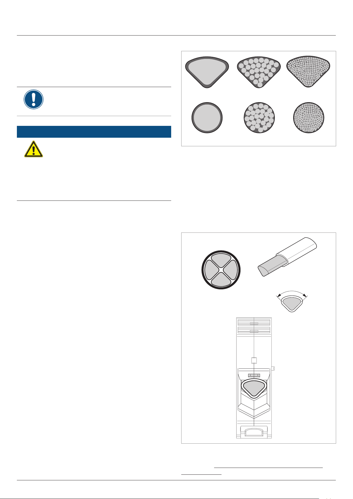
Utilization of thin lm modules
Quick installation guide for solar inverter M88H RPI883M121300 RPI883M122300 EU V1 EN 5017414200_00 2019-11-07
41
Page 42

Connecting to the solar modules (DC)
M88H_122 (CF)
Utilization of thin lm modules
Thin lm modules can be connected to a maximum of 2 DC
connections per DC input in accordance with the following connection diagram.
3
1
2
2
1
1 Use MC4 branch socket PV-AZB4 (Stäubli order number
32.0018) or MC4 branch socket PV-AZS4 (Stäubli order
number 32.0019).
2 Use MC4 fuses of the Stäubli "In-Line-Fuse PV-K/ILF"
series.
3 The M88H_122 (CF) is factory-equipped with 15A string
fuses in the wiring box. These can be replaced by string
fuses with a maximum of 20 A.
When doing so, use 20-A string fuses manufactured by
Littelfuse (Littelfuse part number: 0SPF020.T).
2 2
► Use only the original parts specied above
from Stäubli (formerly Multi-Contact) or
Littelfuse!
Protective devices
When selecting the necessary protective devices (e.g. fuses)
take into account the Maximum reverse current of the solar
modules.
42
Quick installation guide for solar inverter M88H RPI883M121300 RPI883M122300 EU V1 EN 5017414200_00 2019-11-07
Page 43

Connecting to the solar modules (DC)
M88H_122 (CF)
–
+
+ –
Assignment of the DC string fuses to the DC connections
The following illustration is also attached to the inner side of the
cover of the wiring box.
–
–
+
+
Quick installation guide for solar inverter M88H RPI883M121300 RPI883M122300 EU V1 EN 5017414200_00 2019-11-07
43
Page 44

Correctly closing the terminal box
ATTENTION
Impairment of operating response caused by
moisture and dirt.
In order to restore degree of protection IP65
after the completion of installation work,
attach the cover of the wiring box in accordance
with the following instructions.
1. Before screwing on the cover, check all the seals and
surfaces are clean and positioned correctly.
2. Fit the cover (1) and then slide it upwards (2). Do not tilt
the cover.
44
2,37 Nm
3. Tighten the screws by hand at rst and then use a torque
wrench to tighten them crosswise with a torque of 2.37
Nm.
Quick installation guide for solar inverter M88H RPI883M121300 RPI883M122300 EU V1 EN 5017414200_00 2019-11-07
Page 45

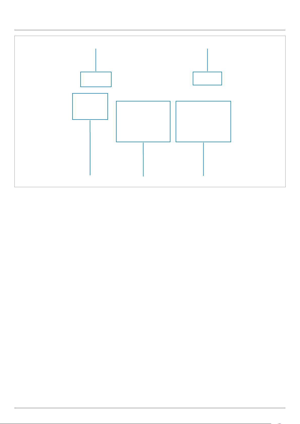
Overview of communications card
Connecting the communication card
Overview
4. Do not skew the screws. The screw heads must be ush
with the surface.
The connections for RS485, the digital inputs,
the dry contacts and the external power-off
(EPO) are all on the communication card. This
means that the installation work can be combined.
1 2
3
1 2 x dry contacts (terminal box)
2 DIP switch for RS485 termination resistor and VCC
3 Digital inputs and external power-off (terminal block)
4 RS485 (terminal block)
5 Protection against electromagnetic interference (EMI)
4 5
Connecting a PC via RS485
If you wish to use a PC with the Delta Service Software for setting up the inverter you will need a USB/RS485 adapter in order
to connect the PC to the inverter.
Inverter USB/RS485 adapter
DATA+ Terminal 3 or 5 D+
DATA– Terminal 4 or 6 D–
ATTENTION
Unwanted currents.
Unwanted currents can ow when multiple
inverters are connected via RS485.
► Do not use GND and VCC.
► If the cable shield is used for providing
lightning protection then the housing of only
one inverter in the RS485 chain should be
grounded.
Quick installation guide for solar inverter M88H RPI883M121300 RPI883M122300 EU V1 EN 5017414200_00 2019-11-07
45
Page 46

Connecting the communication card
Connecting a data logger via RS485
RS485 terminal block
1 2 3 4 5 6
1 VCC (+12 V; 0.5 A)
2 GND
3 DATA+ (RS485)
4 DATA– (RS485)
5 DATA+ (RS485)
6 DATA– (RS485)
Terminal pairs 3/4 or 5/6 can be used. The second terminal pair
is only required when connecting several inverters via RS485.
DIP switch for RS485 termination resistor and VCC
1 VCC (+12 V; 0.5 A)
2 RS485 termination resistor
Connecting a single inverter to a data logger
Termination resistor = ON
ON
Data format
Baud rate 9600, 19200, 38400; Standard: 19200
Data bits 8
Stop bit 1
Parity Not applicable
The baud rate can be set on the inverter display after commissioning; see „Baud rate for RS485“, page 51.
Connecting multiple inverters to a data logger
► If the data logger does not have an integrated RS485 termi-
nation resistor, switch the RS485 termination resistor on the
rst inverter to ON (1).
Termination resistor = OFF Termination resistor = OFFTermination resistor = ON
ON
1 2
Data logger
► Set a different inverter ID at each inverter during commissi-
oning, see „Commissioning – Basic settings“, page 49.
ON
ON
46
1 2
(1)
1 2
1 2
...
RS485
Data logger
Quick installation guide for solar inverter M88H RPI883M121300 RPI883M122300 EU V1 EN 5017414200_00 2019-11-07
Page 47

Connecting the communication card
Connecting the digital inputs, dry contacts and external power-off (optional)
Digital inputs and external power-off (EPO)
To control the active power, an external ripple control receiver
can be connected to the digital inputs.
Pin Short circuit Assigned action
V1 - -
K0 V1 + K0 External power-off (EPO)
K1 V1 + K1 Max. Active power 0%
K2 V1 + K2 Max. Active power 30 %
K3 V1 + K3 Max. Active power 60 %
K4 V1 + K4 Max. Active power 100 %
K5 V1 + K5 Reserved
K6 V1 + K6 Reserved
Dry contacts
The inverter has two dry contacts. The contacts are closed
when the relays energize.
Event Description
Disabled
On Grid Inverter is connected to the mains grid.
Fan failure The fans are defective.
Insulation Insulation test failed.
Alarm
Failure An error message is present.
Fault A failure message is present.
Warning A warning message is present.
The functions for the dry contacts are switched off.
An error, failure or warning message is
present.
After commissioning, the relays for the external power-off can
be dened on the display of the inverter as normally closed or
normally open relays.
An event can be assigned to the dry contacts can be set on the
inverter display after commissioning.
The default setting for both dry contacts is "Disabled".
Quick installation guide for solar inverter M88H RPI883M121300 RPI883M122300 EU V1 EN 5017414200_00 2019-11-07
47
Page 48

Do not work on this equipment until it is located
from both mains and on site generation supplies.
WARNING
Dual supply
Isolate on-site Generation Unit(s) at ____________________________________
Isolate mains supply at _____________________________________________
Attaching warning labels to the inverter
All countries
► Attach all necessary warning labels to the inverter. Always
follow the local regulations.
Some examples of warning labels are listed below.
ATTENTION :
Câbles courant continu
sous tension
ATTENTION :
Câbles courant continu
sous tension
Warning
Two voltage sources
available
Prior to any work, disconnect
both sources
- Distribution network
- PV modules
Examples of warning labels
France
As required by UTE 15-712-1 the following warning labels must
be attached:
Ne pas manœuvrer en charge
Ne pas manœuvrer en charge
Warning label on the wiring box cover
Warning label on the inside of the wiring box cover
48
Quick installation guide for solar inverter M88H RPI883M121300 RPI883M122300 EU V1 EN 5017414200_00 2019-11-07
Page 49

To make the settings as described in this chapter, the inverter must be powered with alternating current (mains grid).
Français
Select language
FRA-Is 60HZ
UK G59-3 230
FRANCE MV
Yes / No
UK G59-3 230
set country:
Are you sure to
Delta prot.
Yes / No
Sunspec prot.
set protocol:
Are you sure to
Yes / No
ID: 1
Are you sure to set
E-Today: 0kWh
Power: 0W
Status: On Grid
10.Sep 2018 14:55
The inverter also needs a DC voltage in order to operate fully from the energy provider.
English
Deutsch
FRA-Is 50HZ
FRA-Is 60HZ
Commissioning – Basic settings
1. Use the and buttons to select the English language and then press the
ENT
button.
2. Use the and buttons to select your country or mains type and then press
ENT
the
3. Check that the correct country or mains type is selected.
button.
Sunspec prot.
Setting ID:
ID=001
If the correct country is selected, use the
entry and then press the
To change the selection, press the
NOTE
The Delta protocol is the Delta Modbus protocol and is intended for utilization with the
Delta Service Software.
ENT
button.
EXIT
and buttons to select the Yes
button.
4. Use the and buttons to select SUNSPEC as RS485 protocol option and
then press the
ENT
button.
5. Check that the correct protocol is selected.
If the protocol is selected, use the
then press the
Press the
NOTE
If multiple inverters are connected to the PV system then a different inverter ID must be
set for each inverter. For example, the inverter ID is used by monitoring systems to uniquely identify each inverter.
ENT
button.
button to change the selection
EXIT
6. Use the and buttons to set the individual digits and then press the
and buttons to select the Yes entry and
ENT
button.
7. Check that the correct inverter ID is set.
If the correct inverter ID is selected, use the
entry and then press the
Press the
The basic settings are now complete. The standard menu is displayed.
þ
→ The inverter starts a self-test lasting approx. 2 minutes. The remaining time is
shown on the display.
button to change the selection
EXIT
Quick installation guide for solar inverter M88H RPI883M121300 RPI883M122300 EU V1 EN 5017414200_00 2019-11-07
ENT
and buttons to select the Yes
button.
49
Page 50

E-Today: 0kWh
Power: 0W
Status: On Grid
10.Sep 2018 14:55
Inverter Info.
General Settings
Active/Reactive Pwr
FRT
Protocol
E-Today: 0kWh
Power: 0W
Status: On Grid
10.Sep 2018 14:55
Inverter Info.
Active/Reactive Pwr
FRT
Password 0 * * *
energy production.
Adj. would affect
Warning:
Grid Settings
Inverter ID: 001
Commissioning – Further settings (optional)
Date and time
Install Settings
Language
Date & Time
Baud rate
10.Sep 2018 14:55
Inverter ID
1. If the default information is displayed, press the
Otherwise, press the
EXIT
button repeatedly until the main menu is displayed.
EXIT
button to open the main menu.
2. Use the and buttons to select the Geneneral Settings entry and then
press the
ENT
button.
3. Press the and buttons to select the entry Date and time and press the
ENT
button.
4. Use the and buttons to congure the value and then press the
Repeat the procedure for the other settings.
ENT
button.
If multiple inverters are connected to the PV system then a different inverter ID must be set for each inverter. For
example, the inverter ID is used by monitoring systems to uniquely identify each inverter.
General Settings
Install Settings
Insulation
Country
1. If the default information is displayed, press the
Otherwise, press the
EXIT
button repeatedly until the main menu is displayed.
EXIT
button to open the main menu.
2. Use the and buttons to select the Install Settings entry and then press
ENT
the
button.
3. This function is protected with password 5555.
Use the
Press the
and buttons to set the individual numerals.
ENT
button to conrm a numeral.
4. Use the and buttons to select the Inverter ID entry and then press the
ENT
button.
Setting ID:
ID=001
50
5. Use the and buttons to congure the value and then press the
Quick installation guide for solar inverter M88H RPI883M121300 RPI883M122300 EU V1 EN 5017414200_00 2019-11-07
ENT
button.
Page 51

Baud rate for RS485
E-Today: 0kWh
Power: 0W
Status: On Grid
10.Sep 2018 14:55
Inverter Info.
General Settings
Active/Reactive Pwr
FRT
Protocol
E-Today: 0kWh
Power: 0W
Status: On Grid
10.Sep 2018 14:55
Inverter Info.
Active/Reactive Pwr
FRT
Password 0 * * *
energy production.
Adj. would affect
Warning:
AC Connection: 3P4W
RCMU: ON
EPO: Normal Close
Anti-islanding: ON
Max. Power: 80000W
AC Connection: 3P3W
RCMU: ON
EPO: Normal Close
Anti-islanding: ON
Max. Power: 80000W
Commissioning – Further settings (optional)
Install Settings
Language
Date & Time
Baud rate
9600
19200
38400
AC connection type
1. If the default information is displayed, press the
Otherwise, press the
EXIT
button repeatedly until the main menu is displayed.
EXIT
button to open the main menu.
2. Use the and buttons to select the General Settings entry and then press
ENT
the
3. Use the buttons and to select the entry Baud Rate and press the
button.
4. Use the and buttons to congure a value and then press the
Repeat the procedure for the other settings.
button.
ENT
ENT
button.
By default, the AC connection type is set to 3P4W (3 phases + N + PE). You only need to change this setting if you
are using an AC system with 3 phases + PE (3P3W).
General Settings
Install Settings
1. If the default information is displayed, press the
Otherwise, press the
EXIT
button repeatedly until the main menu is displayed.
EXIT
button to open the main menu.
2. Use the and buttons to select the Install Settings entry and then press
ENT
the
button.
3. This function is protected with password 5555.
Use the
Press the
4. Use the buttons and to select the AC connection entry and press the
button.
and buttons to set the individual numerals.
ENT
button to conrm a numeral.
ENT
5. Use the and buttons to select the 3P3W entry and then press the
button.
Quick installation guide for solar inverter M88H RPI883M121300 RPI883M122300 EU V1 EN 5017414200_00 2019-11-07
ENT
51
Page 52

E-Today: 0kWh
Power: 0W
Status: On Grid
10.Sep 2018 14:55
Inverter Info.
General Settings
Active/Reactive Pwr
FRT
Password 0 * * *
energy production.
Adj. would affect
Warning:
AC Connection: 3P4W
RCMU: ON
EPO: Normal Close
Anti-islanding: ON
Max. Power: 80000W
E-Today: 0kWh
Power: 0W
Status: On Grid
10.Sep 2018 14:55
Inverter Info.
General Settings
Active/Reactive Pwr
FRT
Password 0 * * *
energy production.
Adj. would affect
Warning:
AC Connection: 3P4W
RCMU: ON
EPO: Normal Close
Anti-islanding: ON
Max. Power: 80000W
Commissioning – Further settings (optional)
External shutdown (E-Power off, EPO)
Install Settings
1. If the default information is displayed, press the
Otherwise, press the
EXIT
button repeatedly until the main menu is displayed.
EXIT
button to open the main menu.
2. Use the and buttons to select the Install Settings entry and then press
ENT
the
button.
3. This function is protected with password 5555.
Use the
Press the
4. Use the buttons and to select EPO entry and press the
5. Use the and buttons to select an option and then press the
Available options
and buttons to set the individual numerals.
ENT
button to conrm a numeral.
ENT
button.
ENT
button.
Active power limitation
Change this setting only after consultation with
Delta customer service.
Install Settings
Normally open: The relay operates as a normally open device.
Normally closed: The relay operates as a normally closed device.
To change this setting, you need a special
password that you receive from Delta customer
service. You can nd the contact information on
the back of this document.
1. If the default information is displayed, press the
Otherwise, press the
EXIT
button repeatedly until the main menu is displayed.
EXIT
button to open the main menu.
2. Use the and buttons to select the Installation Settings entry and then
press the
ENT
button.
3. Enter the password provided by Delta customer service.
Use the
Press the
and buttons to set the individual numerals.
ENT
button to conrm a numeral.
52
4. Use the and buttons to select Max. Power entry and then press the
button.
5. Use the and buttons to congure a value and then press the
Quick installation guide for solar inverter M88H RPI883M121300 RPI883M122300 EU V1 EN 5017414200_00 2019-11-07
ENT
button.
ENT
Page 53

Dry contacts (relays)
E-Today: 0kWh
Power: 0W
Status: On Grid
10.Sep 2018 14:55
Inverter Info.
General Settings
Active/Reactive Pwr
FRT
Password 0 * * *
energy production.
Adj. would affect
Warning:
Grid Settings
RCMU: ON
PID Function: ON
Dry Cont.B Disable
Dry Cont.A Disable
Insulation
Commissioning – Further settings (optional)
Install Settings
DC Injection
Dry Contact
1. If the default information is displayed, press the
Otherwise, press the
EXIT
button repeatedly until the main menu is displayed.
EXIT
button to open the main menu.
2. Use the and buttons to select the Install Settings entry and then press
ENT
the
button.
3. This function is protected with password 5555.
Use the
Press the
and buttons to set the individual numerals.
ENT
button to conrm a numeral.
4. Use the and buttons to select the Dry Contact entry and then press the
ENT
button.
5. Use the and buttons to select a dry contact and press the
ENT
button. The
Disable
On Grid
Fan Fail
current setting is shown after the name of the dry contact.
6. Use the and buttons to select an option and then press the
See „Connecting the digital inputs, dry contacts and external power-off (optional)“,
page 47 for the available options.
ENT
button.
Quick installation guide for solar inverter M88H RPI883M121300 RPI883M122300 EU V1 EN 5017414200_00 2019-11-07
53
Page 54

Technical data
M88H_121 (ST)
Input (DC) M88H_121 (ST)
for AC nominal voltage 400 V
Maximum recommended PV power 90 kW
AC
P
Maximum input power (total/per input)
Symmetrical design 76 kW/38 kW 91 kW/45.5 kW
Asymmetrical design 45.6 kW/30.4 kW 54.6 kW/36.4 kW
Rated Capacity 70 kW 84 kW
Maximum input voltage 1100 V
DC
Operating input voltage range 200 ... 1000 V
Nominal voltage 600 V
Cut-in voltage 250 V
DC
DC
Cut-in power 150 W
MPP input voltage range 200 ... 1000 V
MPP input voltage range with full power
Symmetrical design 540 ... 800 V
Asymmetrical design (60%/40%) 650/440 V
DC
DC
MPP input voltage range at rated power
Symmetrical design 500 ... 800 V
Asymmetrical design (60%/40%) 580/390 V
DC
DC
Asymmetrical design 60/40%; 40/60%
Maximum total input current (DC1/DC2) 140 A (70 A/70 A)
Maximum DC short-circuit current I
SC
180 A (90 A per DC input)
Maximum breaking current 120 A
Open-circuit voltage VOC 1000 V
Number of MPP trackers
Parallel inputs: 1 MPP tracker
Separate inputs: 2 MPP trackers
Number of DC inputs, total (DC1/DC2) 2 (1/1)
Electrical isolation No
Overvoltage category
Surge protection devices
1)
3)
Type 2, replaceable
II
480 V
110 kW
DC
710 V
DC
650 ... 800 V
780/520 V
600 ... 800 V
710/475 V
AC
P
DC
DC
DC
DC
DC
Output (AC) M88H_121 (ST)
AC nominal voltage 400 V
Max. Apparent power
4)
73 kVA
AC
5)
480 V
88 kVA
Rated apparent power 5) 66 kVA 80 kVA
Nominal voltage
7)
400 ± 30% ∆ and Y/480 VAC ± 20% ∆ and Y
3 phases + PE or 3 phases + N + PE
Nominal current 96 A
Maximum current 106 A
Maximum current under fault conditions 115.4 A
rms
Switch-on current 40 A/100 µs
Nominal frequency 50/60 Hz
Frequency range
7)
45 ... 65 Hz
Congurable power factor 0.8 kap ... 0.8 ind
Total harmonic distortion <3% at rated apparent power
DC injection <0.5% at nominal current
Power loss in night mode <3 W
Overvoltage category
1)
Surge protection devices
8)
Type 2, replaceable
III
AC
6)
54
Quick installation guide for solar inverter M88H RPI883M121300 RPI883M122300 EU V1 EN 5017414200_00 2019-11-07
Page 55

Technical data
M88H_121 (ST)
Mechanical details M88H_121 (ST)
Dimensions (W x H x D) 986 × 615 × 275 mm
Weight 84 kg (power module: 68 kg)
Cooling 3 fans
AC connection type Phoenix Contact UKH 150
DC connection type Phoenix Contact UKH 150
Communication Interfaces
General specications M88H_121 (ST)
Delta model name RPI M88H_121
Delta part number RPI883M121200
Maximum efciency 98.8%
EU efciency 98.5%
Operating temperature range -25 ... +60°C
Operating temperature range without derating -25 ... +40°C
Storage temperature range -25 ... +60°C
Relative Humidity 0 ... 100%, non-condensing
Max. operating height 3000 m above sea level.
Noise level (at a distance of 1 m) 75.8 dB(A)
2x RS485, 2x dry contacts, 1x external power-off,
6x digital inputs
Standards and guidelines M88H_121 (ST)
Protection degree IP65
Enclosure rating I
Pollution degree II
Overload behavior Current limit, power limit
Safety IEC 62109-1/-2, CE-compliance
EMC EN 61000-6-2, EN 61000-6-3
Fault-free operation IEC 61000-4-2/-3/-4/-5/-6/-8
Harmonic distortion EN 61000-3-2
Fluctuations and brillations EN 61000-3-3
Mains connection guidelines You will nd the current list at www.solar-inverter.com.
1)
IEC 60664-1, IEC 62109-1
2)
The specied value applies for a temperature of 25°C in the interior of the inverter. At higher temperatures, the value can drop down to 10 A.
3)
EN 50539-11
4)
For cos phi = 1 (VA = W)
5)
Possible under the following conditions: DC input voltage > 540 V; symmetrical design; ambient temperature < 35°C.
6)
Possible under the following conditions: DC input voltage > 650 V; symmetrical design; ambient temperature < 35°C.
7)
AC voltage and frequency range are programmed using the corresponding country specications.
8)
EN 61463-11
Quick installation guide for solar inverter M88H RPI883M121300 RPI883M122300 EU V1 EN 5017414200_00 2019-11-07
55
Page 56

Technical data
M88H_122 (CF)
Input (DC) M88H_122 (CF)
for AC nominal voltage 400 V
Recommended maximum PV power 90 kW
AC
P
Maximum input power (total/per input)
Symmetrical design 76 kW/38 kW 91 kW/45.5 kW
Asymmetrical design 45.6 kW/30.4 kW 54.6 kW/36.4 kW
Rated Capacity 70 kW 84 kW
Maximum input voltage 1100 V
DC
Operating input voltage range 200 ... 1000 V
Nominal voltage 600 V
Cut-in voltage 250 V
DC
DC
Cut-in power 150 W
MPP input voltage range 200 ... 1000 V
MPP input voltage range with full power
Symmetrical design 540 ... 800 V
Asymmetrical design (60%/40%) 650/440 V
DC
DC
MPP input voltage range at rated power
Symmetrical design 500 ... 800 V
Asymmetrical design (60%/40%) 580/390 V
DC
DC
Asymmetrical design 60/40%; 40/60%
Maximum total input current (DC1/DC2) 140 A (70 A/70 A)
Maximum DC short-circuit current I
SC
180 A (90 A per DC input, 10 A per DC string)
Maximum breaking current 120 A
Open-circuit voltage VOC 1000 V
Number of MPP trackers
Parallel inputs: 1 MPP tracker
Separate inputs: 2 MPP trackers
Number of DC inputs, total (DC1/DC2) 18 (9/9)
Electrical isolation No
Overvoltage category
String fuses 15 A
Surge protection devices
1)
3)
Type 2, replaceable
II
2)
480 V
110 kW
DC
710 V
DC
650 ... 800 V
780/520 V
600 ... 800 V
710/475 V
AC
P
DC
DC
DC
DC
DC
Output (AC) M88H_122 (CF)
AC nominal voltage 400 V
Max. Apparent power
4)
73 kVA
AC
5)
480 V
88 kVA
Rated apparent power 5) 66 kVA 80 kVA
Nominal voltage
7)
400 ± 30% ∆ and Y/480 VAC ± 20% ∆ and Y
3 phases + PE or 3 phases + N + PE
Nominal current 96 A
Maximum current 106 A
Maximum current under fault conditions 115.4 A
rms
Switch-on current 40 A/100 µs
Nominal frequency 50/60 Hz
Frequency range
7)
45 ... 65 Hz
Congurable power factor 0.8 kap ... 0.8 ind
Total harmonic distortion <3% at rated apparent power
DC injection <0.5% at nominal current
Power loss in night mode <3 W
Overvoltage category
1)
Surge protection devices
56
8)
Quick installation guide for solar inverter M88H RPI883M121300 RPI883M122300 EU V1 EN 5017414200_00 2019-11-07
Type 2, replaceable
III
AC
6)
Page 57

Technical data
M88H_122 (CF)
Mechanical details M88H_122 (CF)
Dimensions (W x H x D) 986 × 615 × 275 mm
Weight 84 kg (power module: 68 kg)
Cooling 3 fans
AC connection type Phoenix Contact UKH 70
DC connection type Multi-Contact MC4
Communication Interfaces
General specications M88H_122 (CF)
Delta model name RPI M88H_122
Delta part number RPI883M122000
Maximum efciency 98.8%
EU efciency 98.5%
Operating temperature range -25 ... +60°C
Operating temperature range without derating -25 ... +40°C
Storage temperature range -25 ... +60°C
Relative Humidity 0 ... 100%, non-condensing
Max. operating height 3000 m above sea level.
Noise level (at a distance of 1 m) 75.8 dB(A)
2x RS485, 2x dry contacts, 1x external power-off,
6x digital inputs
Standards and guidelines RPI M88H_12x
Protection degree IP65
Enclosure rating I
Pollution degree II
Overload behavior Current limit, power limit
Safety IEC 62109-1/-2, CE-compliance
EMC EN 61000-6-2, EN 61000-6-3
Fault-free operation IEC 61000-4-2/-3/-4/-5/-6/-8
Harmonic distortion EN 61000-3-2
Fluctuations and brillations EN 61000-3-3
Mains connection guidelines You will nd the current list at www.solar-inverter.com.
1)
IEC 60664-1, IEC 62109-1
2)
The specied value applies for a temperature of 25°C in the interior of the inverter. At higher temperatures, the value can drop down to 10 A.
3)
EN 50539-11
4)
For cos phi = 1 (VA = W)
5)
Possible under the following conditions: DC input voltage > 540 V; symmetrical design; ambient temperature < 35°C.
6)
Possible under the following conditions: DC input voltage > 650 V; symmetrical design; ambient temperature < 35°C.
7)
AC voltage and frequency range are programmed using the corresponding country specications.
8)
EN 61463-11
Quick installation guide for solar inverter M88H RPI883M121300 RPI883M122300 EU V1 EN 5017414200_00 2019-11-07
57
Page 58

Space for notes
58
Quick installation guide for solar inverter M88H RPI883M121300 RPI883M122300 EU V1 EN 5017414200_00 2019-11-07
Page 59

Space for notes
Quick installation guide for solar inverter M88H RPI883M121300 RPI883M122300 EU V1 EN 5017414200_00 2019-11-07
59
Page 60

Customer Service - Europe
Austria service.oesterreich@solar-inverter.com 0800 291 512 (toll-free)
Belgium support.belgium@solar-inverter.com 0800 711 35 (toll-free)
Bulgaria support.bulgaria@solar-inverter.com +421 42 4661 333
Czech Republic podpora.czechia@solar-inverter.com 800 143 047 (toll-free)
Denmark support.danmark@solar-inverter.com 8025 0986 (toll free)
France support.france@solar-inverter.com 0800 919 816 (toll-free)
Germany service.deutschland@solar-inverter.com 0800 800 9323 (toll-free)
Great Britain support.uk@solar-inverter.com 0800 051 4281 (toll-free)
Greece support.greece@solar-inverter.com +49 7641 455 549
Israel supporto.israel@solar-inverter.com 800 787 920 (toll-free)
Italy supporto.italia@solar-inverter.com 800 787 920 (toll-free)
Netherlands ondersteuning.nederland@solar-inverter.com 0800 022 1104 (toll-free)
Poland serwis.polska@solar-inverter.com +48 22 335 26 00
Portugal suporte.portugal@solar-inverter.com +49 7641 455 549
Slovakia podpora.slovensko@solar-inverter.com 0800 005 193 (toll-free)
Slovenia podpora.slovenija@solar-inverter.com +421 42 4661 333
Spain soporto.espana@solar-inverter.com 900 958 300 (toll-free)
Switzerland support.switzerland@solar-inverter.com 0800 838 173 (toll-free)
Turkey support.turkey@solar-inverter.com +421 42 4661 333
Other European countries support.europe@solar-inverter.com +49 7641 455 549
5017414200 00
© Copyright – Delta Electronics (Netherlands) B.V. – All rights reserved.
All information and specications can be modied without prior notice.
Quick installation guide for solar inverter M88H RPI883M121300 RPI883M122300 EU V1 EN 5017414200_00 2019-11-07
 Loading...