

Page 1
Operation and Installation Manual for AU Series
M5-TL
M4-TL
M3-TL
AU
Page 2

Page 3

1
This manual is subject to change.
Please check our website at http://www.delta-americas.com/SolarInverters.aspx
for the most up-to-date manual version.
© Copyright – DELTA ELECTRONICS (SHANGHAI) CO.,LTD. - All rights reserved.
This manual accompanies our equipment for use by the end users. The technical instructions and illustrations contained in this manual are to be treated as confidential and no part may be reproduced without the prior written permission of DELTA ELECTRONICS
(SHANGHAI) CO.,LTD. Service engineers and end users may not divulge the information contained herein or use this manual for
purposes other than those strictly connected with correct use of the equipment. All information and specifications are subject to
change without notice.
Page 4

2
Table of Contents
1 General safety information 4
1.1 Safety and Advisory symbols 5
1.2 Safety Instructions 6
2 Introduction 7
2.1 System 8
2.2 Data evaluation and communication 8
2.3 Technical structure of the solar inverter 9
2.4 Ambient temperature 10
2.5 Solar inverter PV input DC voltage range 10
2.6 Efficiency 11
2.7 Equipment overview 11
2.8 Inverter type and safety labels 12
3 Installation 15
3.1 Visual inspection 17
3.2 Installation Infomation 17
3.3 Mounting the inverter 18
3.4 Electrical connection 20
3.5 Mounting the inverter 21
4 Electrical connections 22
4.1 General safety 22
4.2 AC vgrid connection
23
4.3 External DC switch 23
4.4 AC circuit breaker requirements 24
4.5 Grounding conductor
24
4.6 Lightning and surge protection 24
4.7 Multiple inverters 24
4.8 PV string considerations 24
4.9 Inverter connections 25
4.9.1 General information 25
4.9.2 PV array string input information 28
4.9.3 Inverter AC output wire connections 30
5 Commissioning the PV system 30
5.1 Status LEDs 31
5.2 LED Indication 31
Page 5

3
5.2.1 Introduction 31
5.2.2 LED Message 31
5.3 Inverter turn-on procedure 32
5.4 Inverter turn-off procedure
5.3 M Series APP(Android) Manual 32
5.3.1 Introduction 32
5.3.2 Installation 32
5.3.3 Connection 33
5.3.4 Menu Structure 33
5.3.5 Functions 35
6 Production information 43
7 Repair 44
8 Decommissioning, transport, storage, disposal 44
8.1 Decommissioning 45
8.2 Packaging 45
8.3 Transport 46
8.4 Storage 46
8.5 Dispose 46
9 Certificate and technical data 46
9.1 Certificate 46
9.2 Technical data 46
10 Warranty 51
11 Glossary 52
Page 6

4
IMPORTANT SAFETY INSTRUCTIONS
SAVE THESE INSTRUCTIONS
1 General safety information
during installation and maintenance of the inverter. To reduce the risk of electrical shock, and to
ensure the safe installation and operation of the Delta M series inverter, follow these instructions.
AS/NZS and International safety standards. However, like all electrical and electronic equipment,
safety precautions must be observed and followed during installation and operation of the Delta M
series inverters to reduce the risk of personal injury and to ensure a safe installation.
inverters must only be performed by qualified personnel that are licensed and/or satisfy state and
local jurisdiction regulations.
through the entire manual and note all DANGER! WARNING! CAUTION! and NOTICE! statements.
regulations, and all applicable standard.
Page 7
5
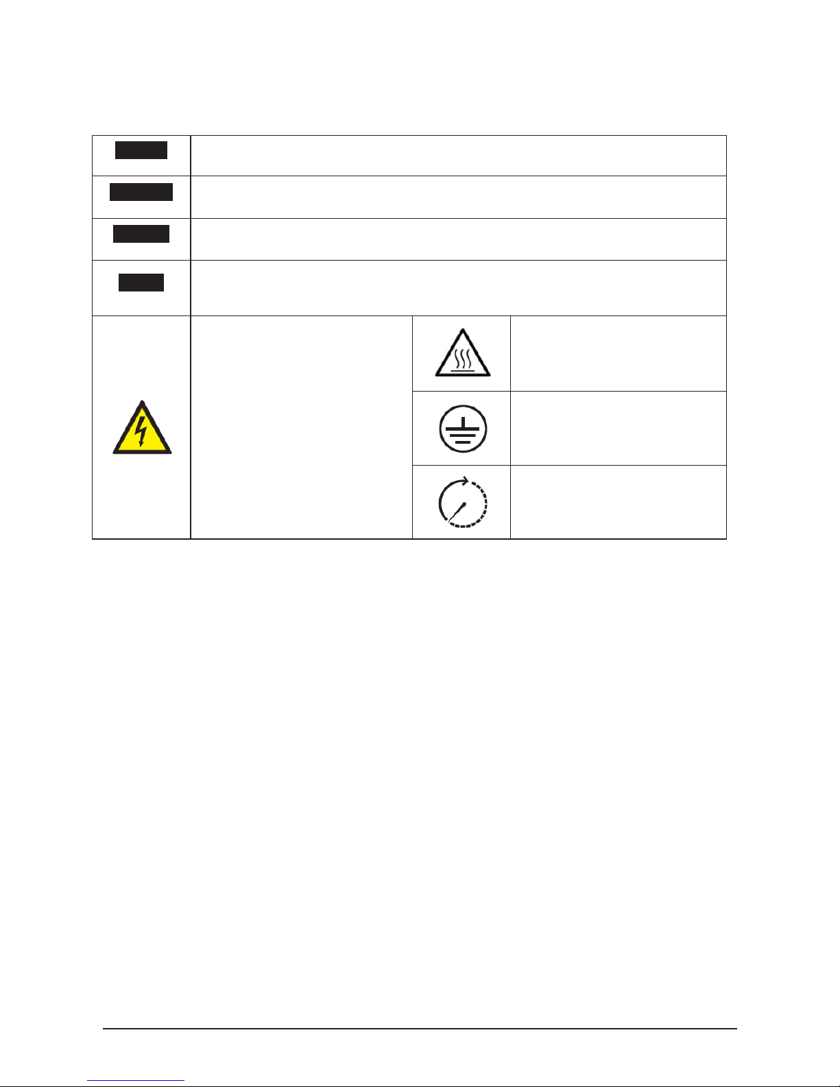
1.1 Safety and Advisory symbols
DANGER
DANGER indicates a hazardous situation which, if not avoided, will result in
death or serious injury.
WARNING
WARNING indicates a hazardous situation which, if not avoided, could result in
death or serious injury.
CAUTION
CAUTION indicates a hazardous situation which, if not avoided, could result in
minor or moderate injury.
NOTICE
NOTICE indicates a situation that can result in property damage if not avoided.
HIGH VOLTAGE WARNING!
Indicates hazardous high
voltages are present, which, if
not avoided, will result in death
or serious injury. Thus, only
authorized and trained
personnel should install and/or
maintain this product.
Hot surface
Equipment grounding
conductor
Wait for a prescribed amount
of time before engaging in the
indicated action.
Page 8

6
1.2 Safety Instructions
The inverter installation must be performed by an authorized electrician in accordance with the local
and SAI Global AS/NZS 5033:2014.
CAUTION - Risk of Electric Shock. When the PV array is exposed to light, it supplies a DC
voltage to this equipment.
CAUTION - Risk of Electric Shock. Do not remove cover. No user serviceable parts inside.
Refer servicing to qualified service personnel.
CAUTION - Risk of electric shock from energy stored in capacitor. Do not remove cover until 5
minutes after disconnecting all sources of supply.
WARNING - For continuous protection against risk of fire, replace only with same type and
ratings of fuse.
WARNING - The RSD Combiner surfaces may become hot. To reduce the risk of burns, do not
touch them.
CAUTION - Electrical installation and final application in Australian market shall consider the
requirements in AS/NZS 3000, AS/NZS 4777.1 and AS/NZS 5033.
CAUTION - Although DC switch may be integrated in product already, external DC switches
fulfill latest AS 60947.3 have to be installed out of the inverter in way per AS/NZS 5033.
CAUTION - DRM function is carried out by external ancillary equipment eShow, please connect
the equipment according to instruction strictly before use.
Page 9

7
2 Introduction
With this device you have acquired a solar inverter for connection of photovoltaic systems to the
grid. This solar inverter is characterized by an advanced housing design and state-of-the-art highfrequency technology, which enable the highest levels of efficiency.
The solar inverter includes series monitoring units, such as anti-islanding protection, display,
RS485 (EIA485) interfaces.
The inverter is usable indoor and outdoor. It fulfills the directives of AS/NZS 5033,AS/NZS 4777,
AS/NZS 4417, AS/NZS 3000 and IEC 62109 for parallel operation of power generation plants on
low-voltage network of regional electrical utility companies.
.
The function of the anti-islanding protection (automatic isolation point for in-plant generation sys-
tems) stipulates compliance with the specifications of AS/NZS 4777 and IEC 62109.2.
In the following technical description, the precise functions are explained to the installer, as well
as the user, which are required for the installation, operational start-up and handling of the solar
inverter.
The inverter not only meets the safety requirements of AS/NZS 5033, but also complies with
the specifications of AS/NZS 4777 for Grid Support Utility Interactive Inverters that support a
more stable utility grid. Delta M TL series were testing to the AS/NZS 4777.2 and AS/NZS 4417
for Regulatory Compliance Mark.
In the following technical description, the precise functions are explained to the installer, as well
as the user, which are required for the installation, operational start-up and handling of the
solar inverter.
Page 10

8
2.1 System
The content of renewable energy with respect to overall power consumption worldwide is increasing annually by approximately 25%. The reason for this rise can be primarily attributed to the constantly increasing demand for power, the increasing interest in environmentally friendly technologies, as well as the increasing costs of non-renewable energy.
By the use of renewable energy sources, the earth‘s atmosphere can be enormously relieved of
increases in CO2 and other harmful gases which result from power generation.
The solar inverter converts direct current from the solar cells into alternating current. This enables
you to feed your self-produced solar energy into the public grid.
Thanks to efficient MPP tracking, maximum capacity utilization of the solar energy plant is ensured even in cases of misty and cloudy skies.
The string concept means that PV modules are always connected in series (in a string) and/or
that strings with the same voltage are connected in parallel to the solar inverter with the aim of
significantly reducing the photovoltaic system’s cabling requirements.
The fact that the modules are connected in strings also means that the photovoltaic system can be
perfectly matched to the solar inverter’s input voltage range.
The inverter is transformer less type without galvanic isolation. Therefore, the inverter may only
be operated with ungrounded PV arrays. Furthermore, the PV array must be installed in
accordance with the AS/NZS 5033(Ungrounded Photovoltaic Power Systems) and the locally valid
regulations for ungrounded PV arrays. Additionally, the PV array (PV modules and cabling) must
have protective insulation and the PV modules used must be suitable for use with this inverter.
PV modules with a high capacity to ground may only be used if their coupling capacity does not
excessed 1,200 nF with 50Hz grid.
2.2 Data evaluation and communication
The integrated interface, processing and communication of the device enables easy operation of
the solar inverter. Monitoring of the operational status and signaling of operational failures are capable of being called up over the interface. The data interfaces enable the downloading of data which
can be evaluated with the aid of a PC system and allow continuous recording of operating data.
The best way of accessing this functionality is via a monitoring system connected to your inverter.
The read-out of the data
over the integrated interface (RS485, BLE4.0, WIFI) is possible only
in solar operation.
Page 11

9
2.3 Technical structure of the solar inverter
The photovoltaic voltage is adjusted so that the maximum power output of the PV modules is also
achieved with different solar irradiation levels and temperatures (MPP-Tracking). These inverters
have quite wide MPP range of suit for variety of PV modules by a variety of manufacturers. Measures must be taken to ensure that the maximum no-load voltage of 600 V is never exceeded.
Please note that the maximum no-load voltage will occur at the lowest temperatures anticipated.
You will find more detailed information about temperature dependency in the data sheet for the PV
modules.
The high-quality aluminum casing corresponds to protection degree IP65 and is
protected by an anti-corrosion finish. The heat sink on the M series inverters
is designed in such a way that operation of the inverter is possible at ambient temperatures from
-22°F to +140°F (-30°C to +60°C) at full power and optimal efficiency for 230 Vac
AC grids.
Metal fins designed into the rear side of the inverter chassis are used to dissipate heat and protect
the unit. An internal temperature control protects the interior of the device. In case of high ambient
temperatures, the maximum transferable power is limited.
The solar inverter is controlled by microcontrollers which provide interface communication and the
values and messages on the front-panel display.
Operator protection requirements are met by electrically isolating the grid from the PV module. The
electrical isolation between the grid and the PV module is equivalent to basic insulation. Maximum
operator protection is ensured by reinforced isolation between the grid,
PV modules and accessible
interfaces (display, RS485 interface ). Relevant standards concerning electromagnetic compatibility
(EMC) and safety are fulfilled.
The solar inverter is functional in grid-parallel operation exclusively. An automatically anti-islanding
function, which was accepted by a certification agency, guarantees secure disconnection in case of
circuit isolation or interruptions in power supply and avoid isolated operation.
Page 12

10
2.4 Ambient temperature
The inverter can be operated in an ambient temperature from -22 °F to 140 °F (-30°C to
+60°C). The following diagram illustrates how the output power of the solar inverter is reduced
automatically in accordance with ambient temperature.
The device should be installed in a well-ventilated, cool and dry location.
Due to tolerrance of temperature sensor and efficiency difference under different PV voltage, this
derating curve may be a litter different from actual behaviors of unit.
Figure 1: Typical derating curve of M series solar inverter
2.5 Solar inverter PV input DC voltage range
0.00%
20.00%
40.00%
60.00%
80.00%
100.00%
120.00%
-30 -20 -10 0 10 20 30 40 50 60 70 80
Maximum output power of unit
Ambient Temperature/°C
Non-
Operating
Range
0
1000
2000
3000
4000
5000
6000
0 100 200 300 400 500 600 700
Non-
operating
range
50V 150V 190V 230V
Voc*:Range of open
M5-TL-AU
M4-TL-AU
M3-TL-AU
Pac/W
Vin/V
120V 530V
Voc*
Range
Page 13
11
Figure 2: M5-TL DC voltage range
2.6 Efficiency
The best efficiency of the solar inverter is obtained at input voltages > 320V for 208V grid, and input
voltages > 380V for 230V grid. The curve is obtained at 230V,380V and 480V grid.
Figure 3: M5-TL efficiency plot
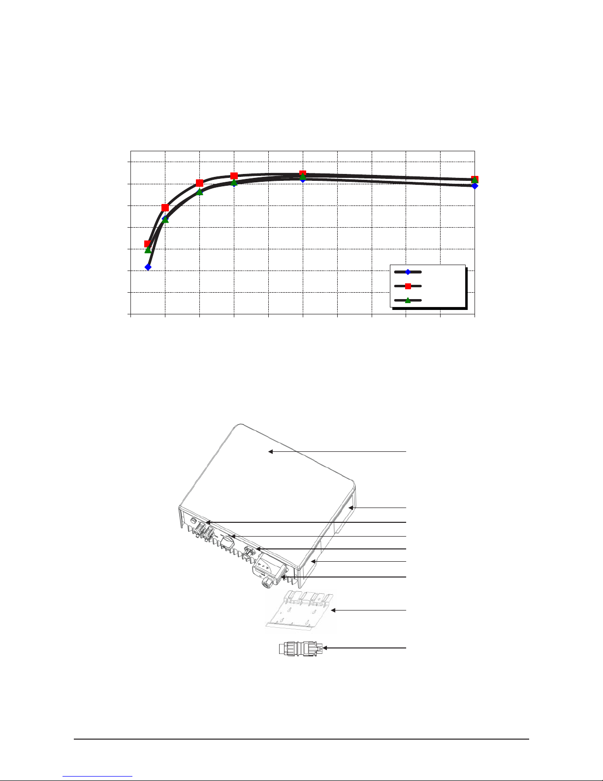
2.7 Equipment overview
Figure 4. Exterior view of solar inverter main components
A further description of the equipment features:
(1) Inverter - This is the inverter section of the assembly. This section is sealed at the factory and
85
87
89
91
93
95
97
99
0% 10% 20% 30% 40% 50% 60% 70% 80% 90% 100%
Efficiency, %
Percentage of Rated Output Power
230 Vdc
380 Vdc
480 Vdc
(1)
(2)
(3)
(4)
(5)
(6)
(7)
(8)
(9)
Page 14
12
there are no user-serviceable parts inside. All wiring to install the inverter is done outside.
(2) Product Label: Specification of product
(3) PV Terminal: Terminal to connect to PV panel
(4) DC Switch: Switch to operate or shutdown the inverter
(5) AC Terminal: Terminal to connect to AC grid
(6) Safety Label: Warnings and Information about safety operation
(7) Communication Box - Inverter operation mode displays and communication (BLE
4.0/WIFI/RS485, optional) to outer device is provided.
(8) Mounting Plate - The inverter ships with a mounting plate that allows easily assembly of the
inverter to a wall
(9) AC Connector: Connect to single phase AC grid line(LN) and ground line, plug it into the AC
Terminal
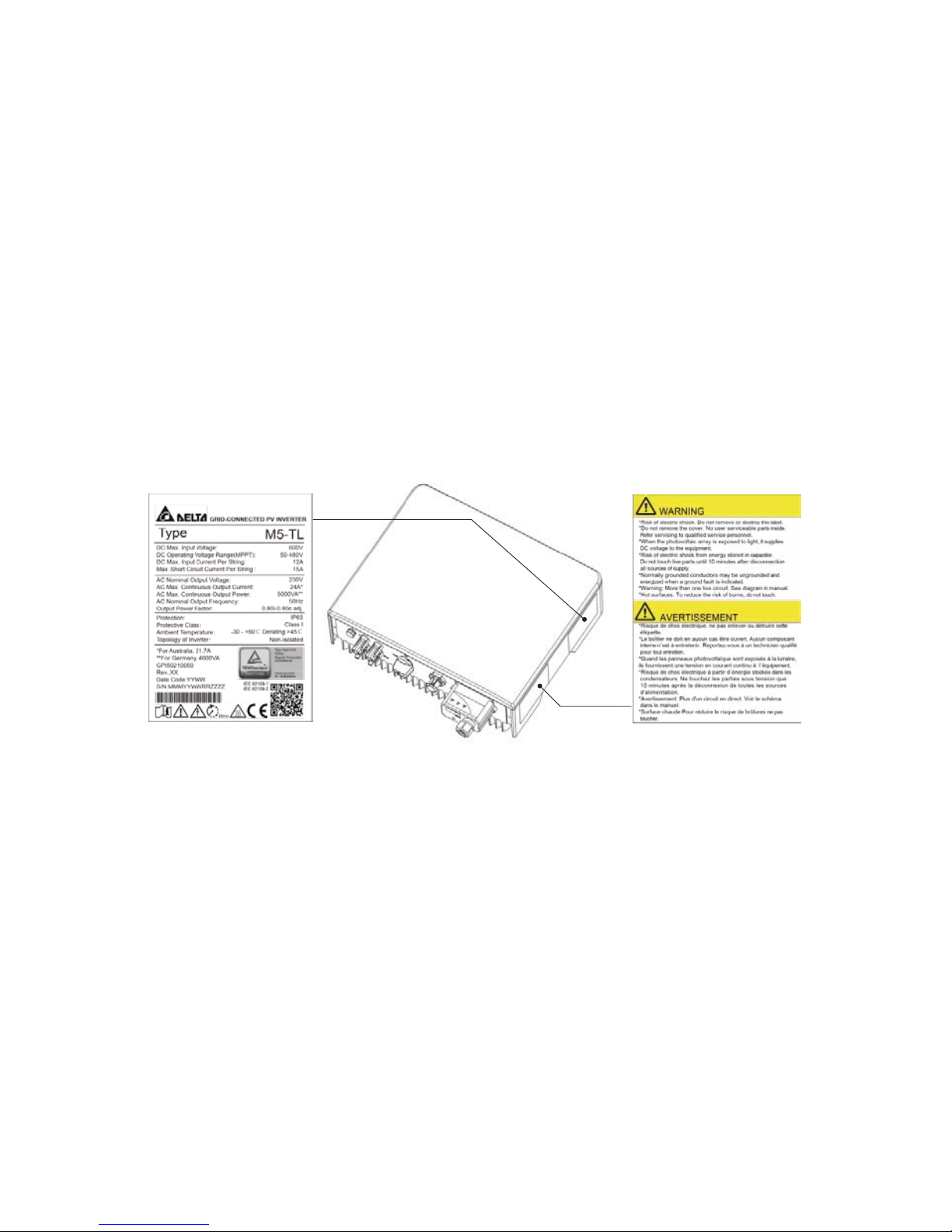
2.8 Inverter type and safety labels
Figure 5. Labels location
The type label is shown in figure 5. Different type labels can be found on the M series TL inverter,
the inverter serial number can be found on the type label. Please note that capital letters in
Serial Number are used as placeholders to indicate the variable information for the inverter.
The main caution label in English is on the left side of the inverter.
Page 15
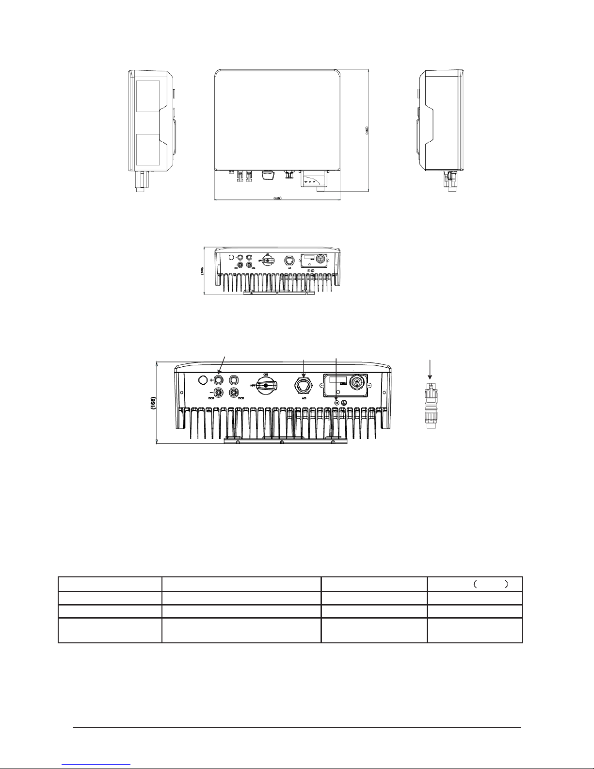
13
Figure 5. Dimensions of M series inverter
Figure 6. Wiring terminals of M series inverter
(1) PV terminals
(2) AC terminal (Output Side)
(3) Grounding terminal
(4) AC terminal (Wiring side)
The connection terminal is as below:
Model
Manufacturer
Wiring(AWG)
AC terminal
PRC 3-FC-FS6 8-21-1410661
Pheonix
10
DC terminal MALE
32.0013P0001-UR
MC
14
DC terminal
FEMALE
32.0012P0001-UR MC 14
(1) (2) (3) (4)
Page 16

14
Page 17
15
3 Installation
WARNING!
AVERTISSEMENT!
WARNING!
AVERTISSEMENT!
WARNING!
AVERTISSEMENT!
Read all of these instructions, cautions, and warnings for the Delta
M series inverter and associated PV array documentation.
Installation and commissioning must be performed by a licensed
electrician in accordance with local and SAI Global AS/NZS
5033:2014 requirements.
The installation and wiring methods used in the installation of this
inverter. Australia must comply with all local, utility, SAI Global
standards AS/NZS 5033:2014 and IEC 62109 requirements.
Page 18
16
WARNING!
AVERTISSEMENT!
These servicing instructions are for use by qualified personnel only.
To reduce the risk of electric shock, refer all servicing to factory
qualified service personnel. No user service parts are contained
inside the inverter.
CAUTION!
PRUDENCE!
CAUTION!
PRUDENCE!
CAUTION!
PRUDENCE!
INFORMATION!
INFORMATIONS!
The secondary short-circuit current rating is increased at the transfer connection point to the public electricity supply system by the
nominal current of the connected solar inverter.
To reduce the risk of fire, connect only to a circuit provided with
branch circuit overcurrent protection in accordance with AS/NZS
3000 requirements. PV overcurrent protective device with 20 A
per string is necessary for inverter connection to PV panel.
This unit or system is provided with fixed trip limits and shall not be
aggregated above 30KW on a single point of common connection.
In order to be able to carry out an energy measurement, a KWH
revenue meter must be attached between the networks feed-in
point and the solar inverter.
Page 19

17
3.1 Visual inspection
All Delta M series inverters are 100% tested, packaged in a heavy duty cardboard shipping carton,
and visually inspected before leaving our manufacturing facility. If you receive the inverter in a
damaged shipping carton, please reject the shipment and notify the shipping company.
Verify Delta M series shipping carton contains:
a. Correct Delta M series inverter model: M5-TL, M4-TL or M3-TL
b. Mounting plate
c. Quick Installation Guide
d. AC terminal
Visually inspect the Delta M series inverter for any physical damage such as a bent heatsink fin
and dented chassis.
If the inverter appears to be damaged or if the inverter needs to be returned, please contact your
local Delta representative.
No user serviceable parts are contained in the inverter section.
Do not attempt to open or repair the inverter. The inverter section
is factory sealed to maintain its IP65 rating and opening the top
cover of the power head will void the inverter warranty.
3.2 Installation Information
1. Install the inverter on a non-flammable support base.
2. The inverter must be mounted vertically on a flat surface.
3. A minimum distance of 6 inches (15.2 cm) of unobstructed clearance on all sides to promote
free convection is required.
4. Ensure the mounting hardware and structure can support the weight of the inverter.
5. Ensure the mounting hardware meets the appropriate building code.
6. Avoid installation on resonating surfaces (light construction walls etc.).
7. Installation can be indoors or in protected outdoor areas with shielding such as roof.
8. Avoid direct sun exposure.
9. Ensure inverter ambient temperature is within -22°F to +122°F (-30°C to +60°C) for optimal
efficiency of the PV system.
10. Chose a mounting height for easy viewing of the display.
11. Despite having a IP65 enclosure certification, the inverter must not be exposed to heavy
soiling.
12. Unused connectors and interfaces must be covered through sealing connectors.
Page 20

18
3.3 Mounting the inverter
Figure 7. Mounting the inverter vertically
Please make sure the inverter is installed vertically, especially if it is to be installed outdoors.
Figure 8. Inverter installation clearance
Please ensure the inverter is mounted with safe clearance and larger margin shall be left with higher
ambient temperature.
Page 21

19
Figure. 9 Dimension drawing of mounting plate
1. Mount the mounting plate to the wall with at least 4 screws and anchors (Ø 6mm). With 4
screws use 4 holes A or 4 holes B (see Figure 9). You can use the mounting plate as
a template for marking the positions of the boreholes.
2. Tighten the screws firmly to the wall.
Figure 10. Mounting the plate and the inverter to the wall
1. Figure 13: Installing the plate and inverter on a wood stud wall Using the mounting plate as a
template, mark four screw holes onto the wall. For 16 inches (40.6 cm) on center stud
mounting, use the four holes that are indicated for this purpose in the figure. Make sure the
holes are in the center of each stud before marking the drill location.
2. After marking the screw hole locations, drill the pilot holes for the appropriate screw type
that will hold the weight of the inverter in the selected material. 1/4“lag bolts are recom-
mended for mounting on wood framed walls.
3. Align the mounting plate over the pilot holes and install the mounting hardware to mounting
surface. Please tighten to the recommended torque necessary to hold the mounting plate
firmly to the wall surface type.
4. As the solar inverters are heavy, they should be lifted carefully.
5. With at least two persons on either side of the inverter, lift it up and place it carefully onto
the mounting plate. Install two screws as shown in the figure 9 to secure the
Page 22

20
device.
6. Check that the solar inverter is seated securely on the wall.
It is recommended to use stainless steel screws, especially if installed outdoors. Be sure to
verify sheer and pullout strength of anchors or other wall attachments.
3.4 Electrical connection
·Electrical connections shall conform to the installation specifications of the country/region
where the equipment is located.
·Make sure the PV and AC side are disconnected before connecting, otherwise the high voltage of
the inverter may lead to electric shock hazard.
Connect the PV terminal:
·Connect the PV terminal of the panel side to the PV terminal of the inverter side.
·Make sure the cable polarity is correct before the PV connection.
·When the click like “clatter” is heard, the input wire can’t be pull-out by hand,
the connection is successful.
Connect the AC terminal:
·Cross-sectional area of the wire: 4mm²-6mm²
·Applicable outer diameter of the cable: 8mm²-21mm²
Figure 11. Install AC terminal
Page 23

21
3.5 Install protective ground wire
·The inverter housing is grounded, as shown in Fig.12
·Cross-sectional area of wire: 4mm²-6mm².
·Screw torque: 1.4 N.m
Figure 12 Protective grounding
Page 24

22
4 Electrical connections
4.1 General safety
WARNING!
AVERTISSEMENT!
WARNING!
AVERTISSEMENT!
DANGER!
DANGER!
WARNING!
AVERTISSEMENT!
CAUTION!
PRUDENCE!
Read all of these instructions, cautions, and warnings for the Delta
M series inverter and associated PV array documentation.
Installation and commissioning must be performed by a licensed
electrician in accordance with local, state, and AS/NZS 5033
requirements. Use AWG14 for PV wiring and AWG10 for AC
wiring or greater 90°C (194 °F), copper solid or stranded wire for
all DC and AC wiring to the M series inverter to optimize system
efficiency.
PV solar arrays produce hazardous voltages and currents when
exposed to light which can create an electrical shock hazard. Using
dark opaque sheets cover the PV solar array before wiring or connecting cable terminations.
Before connecting the Delta M series inverter to the AC distribution grid, approval must be received by appropriate local utility as
required by national and state interconnection regulations, and must
be connected only by qualified personnel.
Do not attempt to open or repair the inverter as the inverter is factory
sealed to maintain its IP65 rating and will void the inverter warranty.
The PV AC output circuits are isolated from the enclosure. The PV
system PE Conductor when required by AS/NZS 3000.
Page 25

23
4.2 AC grid connection
M series TL AU inverters are designed for single phase grid. Nominal voltage is 230 Vac,
frequency is 50 Hz. Other technical requests should comply with the requirement of the local
public grid.
4.3 External DC switch
Although DC switch may be integrated in product already, external DC switches fulfill latest AS
60947.3 have to be installed out of the inverter in way per AS/NZS 5033. External DC switch
capacity shall be no less than 20 A per string.
Page 26

24
4.4 AC circuit breaker requirements
A dedicated circuit breaker in the building circuit panel is required for each Delta M series inverter
that is installed. There should be a circuit breaker or fuse to protect each AC line, L and N. The
circuit breaker should be able to handle the rated maximum output voltage and current of the
inverter. Please refer to the table below to determine the appropriate circuit breaker size to avoid
potential fire hazards. The SAI Global AS/NZS 5033 or applicable local electrical codes must be
followed when determining maximum branch-circuit over-current protection requirements.
Inverter model
Recommended AC branch protection
M3-TL
2-pole, 20 A 230 Vac
M4 -TL
2-pole, 25 A 230 Vac
M5 -TL
2-pole, 30 A 230 Vac
Please note that there is an exception to the requirement of a dedicated circuit breaker in the building circuit panel for each inverter if there exists a dedicated PV system AC subpanel that is used
to combine multiple inverters. In this case, only one breaker at the main building service panel
should be installed for a multiple inverter installation utilizing a dedicated PV system AC subpanel.
4.5 Grounding conductor
Per AS/NZS 5033, a grounding conductor must be installed, and the PE conductor must be sized
in accordance with AS/NZS 3000. The grounding conductor should be terminated at the PE screw
terminal inside the wiring box compartment. Grounding wire shall be selected based on the local
rules and its diameter is no less than 4 mm
2
. Green, yellow double color line is recommended for
protective grounding and secondary grounding terminal at the bottom of inverter shall be reliable
grounded as well as the grounding inside AC terminal, or personal injury may be caused.
4.6 Lightning and surge protection
Delta M series AU inverters are designed and certified to meet stringent AS/NZS 4777 and IEC
62109-2 AC lighting and surge requirements; however, every PV installation is unique, thus
additional external AS/NZS AC and DC surge protection and solid grounding practice is
recommended
4.7 Multiple inverters
Multiple Delta M series inverters are permitted at a common location if all applicable SAI global,
local building codes and local utility commissioning guidelines are met. In addition, each inverter
should have its own dedicated AC branch protection circuit breaker and a dedicated PV string/
array, not to exceed the inverter’s ratings.
Page 27

25
4.8 PV string considerations
There are a large number of PV module string combinations that will offer optimal performance
from either the M3-TL-AU, M4-TL-AU and M5-TL-AU inverters thanks to its wide full
power MPP range (50 V – 48
1
0 V)
1
INFORMATION!
INFORMATIONS!
Follow the temperature multiplication factors given in AS/NZS 5033
table and the PV module manufacturer specified V/Temp coefficient to ensure PV string voltage is less than < 600 Vdc. Maximum
inverter PV input voltage for all possible weather conditions in the
location of installation.
System wiring voltage losses should be no greater than 1 to 2
percent for optimal system efficiency and performance.
4.9 Inverter connections
4.9.1 General information
Installation and commissioning must be performed by a licensed
electrician in accordance with local, state, and AS/NZS 3000
requirements.
Inputs and output circuits of this unit are isolated from the enclosure. System grounding must be done in accordance with the
AS/NZS 3000 and Compliance is the responsibility of the installer.
Page 28

26
WARNING!
AVERTISSEMENT!
Ensure no live voltages are present on PV input and AC output
circuits, and verify that the DC disconnect, AC disconnect, and dedicated AC branch circuit breaker are in the “OFF” position, before
inverter installation.
DANGER!
DANGER!
CAUTION!
PRUDENCE!
INFORMATION!
INFORMATIONS!
WARNING!
AVERTISSEMENT!
PV solar arrays produce hazardous voltages and currents when
exposed to light which can create an electrical shock hazard.
Using dark opaque sheets cover the PV solar array before wiring
or connecting cable terminations
Before any electrical wiring can be connected to the inverter, the
inverter must be permanently mounted.
Use solid or stranded copper conductors only.
AWG14 for PV, AWG10 for AC, is recommended wire size.
.
Inverter warranty is VOID if the DC input voltage exceeds the inverter 600 Vdc maximum.
Page 29

27
DC-Bus
Power
controller
Antiislanding
protection
Communication
Operating and system control
A
String A
DC
DC
String B
-
MPP-
Tracker
-
-
~
AC
Public
grid
B
Booster
Inverter
M series AU inverter
Figure 11: M series TL Inverter electrical diagram
Page 30

28
4.9.2 PV array string input connections
To ensure maximum protection against hazardous contact voltages
while assembling photovoltaic installations, both the positive and
the negative leads must be strictly isolated electrically from the
protective ground potential (PE).
CAUTION!
PRUDENCE!
Verify DC conductor voltage polarity with voltage meter because
damage to the inverter could result if incorrect DC input polarity is
connected.
Risk of damage. Be sure that the polarity is correct when you make
the connection. Connecting it wrongly will cause damage to the
inverter.
Page 31

29
INFORMATION!
INFORMATIONS!
INFORMATION!
INFORMATIONS!
Risk of electric shock and fire. Use only with PV modules with a
maximum system voltage of rating of 600V or Higher.
Electric shock hazard. The DC conductors of this photovoltaic
system are ungrounded and may be energized.
Electric shock hazard. The DC conductors of this photovoltaic
system are ungrounded but will become intermittently grounded
without indication when the inverter measures the PV array
isolation.
The PV Array positive or negative leads must not be connected to
ground before the inverter!
All screw terminals accept solid or stranded copper 14 – 6 AWG
wire only.
B
D F
A
Page 32

30
4.9.3 Inverter AC output wire connections
WARNING!
AVERTISSEMENT!
– Read all of the instructions, cautions, and warnings for the
Delta M Series Inverter, associated PV array documentation.
– Installation and commissioning must be performed by a
licensed electrician in accordance with local, state, and
AS/NZS 3000 requirements.
– Ensure no live voltages are present on PV input and AC
output circuits, and verify that the DC disconnect, AC
disconnect, and dedicated AC branch circuit breaker are in
the “OFF” position, before inverter installation.
– Verify that dedicated 2-pole 230 Vac circuit
breaker in the building electrical service panel is turned-off.
5 Commissioning the PV system
WARNING!
AVERTISSEMENT!
WARNING!
AVERTISSEMENT!
WARNING!
AVERTISSEMENT!
Read all of these instructions, cautions, and warnings for the
Delta M series inverter and associated PV array documentation.
Installation and commissioning must be performed by a licensed
electrician in accordance with local, state, and AS/NZS 4777
requirements.
Verify that the dedicated 2-pole 230 Vac circuit breaker
in the building electrical service panel is turned-off.
Page 33

31
Disconnect in the “OFF” position, verify the PV input polarity
once more simply by carefully using a 600 V, DC rated digital
volt meter and probing the positive (+) and negative (-) PV array
connections.
5.1 Status LEDs
Label Designation Color
Power Operation Green
Fault Fault Red
Info Infomation Yellow
Information on the LED messages is provided in “8. Diagnosis and maintenance”.
5.2 LED Indication
5.2.1 Introduction
Function
There are 3 LEDs in the front side of the inverter
5.2.2 LED Message
The LEDs indicate the operational status of the inverter
Message
Category
LED Signal
Message Explanation
LED Color Status Behavior
Normal
Operating
POWER Green <On> Constant on The inverter feeds in grid.
Sync. POWER Green <Blink> 1s on, 1s off
The inverter is synchronizing
with grid.
Information INFO Yellow <On> Constant on
The inverter has alarm and
user can search for details via
APP.
Grounding
fault
FAULT Red <On> Constant on Grounding fault occurs.
Inverter
fault
FAULT Red <On> Constant on
The inverter has fault and user
can search for details via APP.
Firmware
upgrade
POWER
Green
<Blink>
0.5s on,0.5s off
The inverter is under firmware
upgrade.
INFO
Yellow
<Blink>
0.5s on,0.5s off
Initialization
POWER Green <On> On until done
Inverter initialize when the DC
voltage rise to startup
threshold.
INFO
Yellow <On> On until done
FAULT Red <On> On until done
Page 34

32
5.3 Inverter turn-on procedure
Compatibility
1. Turn on the DC disconnect (turn to “ON” position, if rapid shutdown device is connected
turn on AC disconnect firstly).
2. Check for inverter initialization (all three LED indicators are illuminated).
3. Turn on the dedicated 2-polo 230Vac circuit breaker in the building electrical service
panel (put in closed position).
4. If there is AC disconnect, turn on the AC disconnect.
5. Refer to section 6 for setup process that needs to be completed before the inverter can
begin feeding power to the grid.
5.4 Inverter turn-off procedural
1. If there is AC disconnect, turn off the AC disconnect.
2. Turn off the dedicated 2-polo 230Vac circuit breaker in the building electrical
service panel (put in open position).
3. Turn off the DC disconnect (turn to “OFF” position).
5.5 M Series APP(Android) Manual
5.5.1 Introduction
Function
M Series APP is a mobile application software to communicate with inverter system for real-time
status monitoring, parameter configuration, RMA request form generating and daily maintenance
via Bluetooth Low Energy.
5.5.2 Installation
Compatibility
1. Requires android 4.4(KitKat) or later.
2. BLE supported.
3. Internet over WIFI.
Procedure
Search “M Tool” in Google Play, download and install the application.
The app icon will show up on the desktop.
Page 35

33
5.5.3 Connection
Procedure
Step 1. Open app, allow all the permissions required.
Step 2. Close guide page, guide page only shows at the first time.
Step 3. Click on to refresh and display device list.
Step 4. Connect the device with the following method:
Press on to get connection with it.
Step 5. Wait in the monitor page until the progress bar finish and disappear.
5.5.4 Menu Structure
Page 36

34
Page 37

35
5.5.5 Functions
5.5.5.1 Monitor - Display Real-time Status and Power Curve
Procedure
Step 1. After connecting device, monitor page will show real-time status of today, including
power curve, PVs voltage, PVs current, AC voltage, AC current, energy and instant
power. It will show device name and firmware version, and synchronize date and time
automatically.
5.5.5.2 IV Scan
Step 1. Press on to display menu.
Page 38

36
Step 2. Press on “IV Scan” .
Step 3. Select a PV button to click, wait until the dialog disappear to show IV curve
and PV curve.
Page 39

37
5.5.5.3 Configuration
Press “App Settings” to enter configuration. Configuration contains basic settings and other
settings.
Page 40

38
Basic
1 Enable Guide
Guide page shows only once at the first time, enable the switch to show it one more time.
2 Enable Snack Bar
Snack bar pops up from the bottom of screen to show some tips. Click the switch to enable
or disable it.
3 Enable Device Filter
Device filter allows the scanner to ignore the irrelevant devices. Click the switch to enable
or disable it.
4 Keep Connection
Connection interruption will occur if the connection is not active in a period of time. Keep
connection allows app to send pin message to device regularly to avoid interruption. Click
the switch to enable or disable it.
Others
1 Version
Show current version number.
5.5.5.4 Error Log
Procedure
Step 1 Click on button to back to monitor.
Step 2 Press on
to display menu.
Step 3 Press on “Error Log”
Step 4 Press on “Read Log”
Page 41

39
5.5.5.5 History – Display PV and AC History
Procedure
Step 1 Click on to back to monitor.
Step 2 Press on
to display menu.
Step 3 Press on “History” to check history data.
Page 42

40
5.5.5.6 User Information
Procedure
Step 1 Click on to back to monitor.
Step 2 Press on to display menu.
Step 3 Press on “Edit” to enter user info page.
Step 4 Edit user information.
Page 43

41
Step 5 Click on “Save” to save data.
5.5.5.7 Update
Procedure
Step 1 Click on to back to monitor.
Step 2 Press on to display menu.
Step 3 Press on “Upgrade” to enter upgrade page.
Step 4 Pick one BIN file to update.
Page 44

42
5.5.5.8 RMA
Procedure
Step 1 Click on to back to monitor.
Step 2 Press on to display menu.
Step 3 Press on “RMA” to enter RMA page.
Step 4 Complete user info if it shows “incomplete”
Step 5 Click on RMA button.
Step 6 Pick your email app and send email.
Page 45

43
.
6 Production information
All production information is provided for orientation purposes
only. The measuring devices and meters provided by the electricity supply company are the authoritative source of information
for invoicing.
Page 46

44
7 Repair
Danger of death from hazardous voltage.
Hazardous voltage is applied to the solar power inverter during
operation. Hazardous voltage is still present 5 minutes after all
power sources have been disconnected.
Never open the solar power inverter. The solar power inverter
contains no components that are to be maintained or repaired by
the operator or installer. Opening the cover will void the warranty.
The solar power inverter contains no components that are to be
maintained by the operator or installer.
8 Decommissioning, transport, storage, disposal
Danger of death or severe injuries from dangerous voltage
Disconnect the solar inverter from the grid before removing or
inserting the AC connector.
Page 47

45
Danger of death or severe injuries from dangerous voltage
Dangerous voltages can be present at the DC connections of the
solar power inverter.
Never disconnect the PV modules when the solar power inverter is
under load. First switch off the grid connection so that the solar power
inverter cannot feed energy into the grid. Then open the DC
disconnector.
Secure the DC connections against being touched.
Danger of injury due to heavy weight
The solar power inverter is heavy (see “9.2 Technical data”).
Incorrect handling can lead to injuries.
The solar power inverter must be lifted and carried by two
people.
8.1 Decommissioning
1. Switch off the AC cable to be free of voltage.
2. Open the DC disconnector.
3. Remove all cables from the solar power inverter.
4. Unscrew the solar power inverter from the wall bracket.
5. Lift the solar power inverter from the wall bracket.
8.2 Packaging
Use the original packaging or packaging of the same quality.
Page 48

46
Input(DC)
V
MAX
PV
600 V
Nominal voltage
380 V
Max. Operating Voc
530 V
Operating MPP voltage range
50 ~ 480 V
Full Power MPP voltage range
150~480 V 190~480 V 230~480 V
Max. Input current (Per String)
12A
Max. short circuit current
@ STC
15A/15A
Start PV voltage
120 V
Stop PV voltage (PCE
shutdown)
50 V
Backfeed current
0
Allowed DC loading ratio
1.5
Overvoltage category
II
DC disconnect
Internal
MPP tracker
2
2 2
Input strings available
1-1 1-1 1-1
8.3 Transport
Always transport the solar power inverter in the original packaging or packaging of the same quality.
8.4 Storage
Always store the solar power inverter in the original packaging or packaging of the same quality.
Observe the specifications relating to storage conditions described in chapter “9.2 Technical data”.
8.5 Dispose
Dispose of the solar power inverter in a technically appropriate manner according to the legal
requirements of your country.
9 Certificate and technical data
9.1 Certificate
Please check our web site at: http://www.delta-americas.com/SolarInverters.aspx for the most
recent certificates.
9.2 Technical data
Model M3-TL-AU M4-TL-AU M5-TL-AU
Page 49

47
Array insulation resistance
detection
500 kΩ (> V
MAX
PV/30 mA)
Continuous residual current
threshold value
250 mA (I
LIMIT
: 300 mA)
Continuous residual current trip
time
180 ms(T
LIMIT
: 300 ms)
Sudden residual current threshold
value
20 mA(I
LIMIT
: 30 mA) 50 mA (I
LIMIT
: 60 mA) 130 mA (I
LIMIT
: 150 mA)
Sudden residual current trip time
180 ms (T
LIMIT
: 300 ms) 50 ms (T
LIMIT
: 150 ms) 0 ms (T
LIMIT
: 40 ms)
Output(AC)
Model
M3-TL-AU
M4-TL-AU
M5-TL-AU
Nominal power 3000 W 4000 W 5000 W
Maximum output power 3000 W 4000 W 5000 W
Maximum output power
3000 VA 4000 VA 5000 VA
Operating voltage range
180~275 V
Rated output voltage
230 V
Max continuous current 16A 20A 24 A(21.7 A for AU)
Maximum output overcurrent
protection
25 A 30 A 35 A
Maximum inrush current
5 A 5 A 5 A
Maximum output fault current
18 A 24 A 32 A
Nominal frequency
50 Hz
Operating frequency range
45.0 ~ 55.0 Hz
Standby power consumption
< 10 W
Night consumption
< 1 W
iTHD @ nominal power
< 3%
Acoustic noise
40 dB
Overvoltage category
III
Power factor @ nominal power
> 0.99
Adjustable power factor range
0.80i ~ 0.80c
Model
M3-TL M4-TL M5-TL
PV & GRID CONNECTION
Page 50

48
Type of inverter Non-isolated
Type of NS protection Integrated
Separated by Transformerless
Protective class I
Max. efficiency 98%
Pollution degree PD 3
CEC efficiency
97.2% @ 230V
Operating temperature range
"-30 ~ 60°C
derating above 45°C"
Storage temperature range
Humidity
-40 ~ 185°F (-40 ~ 85°C)
4 ~ 95%
Max. operating altitude
3000 m
CONSTRUCTION
Model
M3-TL M4-TL M5-TL
Page 51

49
Size L x W x D inches (L
x W
x D mm)
17.7 x 15 x 6.3 in. (450 x 383 x 160)
Weight
33 lbs (15 kg)
Cooling
AC connectors
Natural Convection
Spring terminals in connection box
Compatible Wiring Gauge
in AC
AWG 10 ~ AWG 6
DC connectors
BLE 4.0, RS485/WiFI (Optional)
Compatible Wiring Gauge
in DC
Diecast Aluminum and Plastic
Communication interface
Model
M3-TL M4-TL M5-TL
MECHANICAL DESIGN
Compatible with battery
Model
M3-TL M4-TL M5-TL
STANDARDS / DIRECTIVES
Enclosure protection rating
IP65
Safety AS/NZS 4777, IEC 62109-1, IEC 62109-2
EMC
IEC 61000-6
Anti-islanding Method
Reactive Power Injection
WARRANTY
Standard warranty 5 years
Page 52

50
Delta Electronics Australia Pty Ltd.
Melbourne Main Office :
Unit 20-21, 45 Normanby Road, Notting Hill VIC 3165, Australia
Sydney Office:
B46/24-32 Lexington Drive, Bella Vista NSW 2153,
Australia
Tel: +61 3 9543 3720
Fax: +61 3 9544 0606
Service Line : 1300 DELTA E ( 1300 333823 ) 24/7
Service Support email: Solarsupport@deltaww.com
Page 53

51
10 Warranty
The M series grid-tied inverter includes a standard 5-year warranty in effect from the time your
inverter is commissioned. For all the M series AU warranty terms and return procedures, please
refer to our web site at http://www.delta-americas.com/Sola- rInverters.aspx for further information.
For assistance with warranty repairs or returns you may contact our North America support hotline
at: 1-877-442-4832 or via email at support.usa@solar-inverter.com.
Page 54

52
11 Glossary
AC
Abbreviation for “Alternating Current”.
Anti-islanding protection
This is a unit for grid monitoring with assigned switching elements (anti-islanding protection) and is
an automatic isolation point for small power generation systems (to 30 kWp).
Basic Insulation
Insulation to provide basic protection against electric shock.
CEC
Abbreviation for the California Energy Commission
CEC Efficiency
CEC Efficiency is the California Energy Commission Efficiency rating, a performance rating for
modules and inverters based on the real environment that a system will be in.
CSA
Abbreviation for the Canadian Standards Association.
DC
Abbreviation for “Direct Current”.
EMC
The Electro-Magnetic Compatibility (EMC) concerns the technical and legal basics of the mutual
influencing of electrical devices through electromagnetic fields caused by them in electrical engineering.
Galvanic isolation
No conductive connection between two component parts.
GND
Ground
IEEE
The Institute of Electrical and Electronics Engineers or IEEE (read I-Triple-E) is an international
non-profit, professional organization for the advancement of technology related to electricity.
Page 55

53
Initialization
Under initialization (cf. English to initialize) is understood the part of the loading process of a program, in which the storage space required for the execution (e.g. variable, code, buffers ...) for the
program is reserved and is filled with initial values.
Local utility company
A local utility company is a company which generates electrical energy and distributes it over the
public grid.
MPP
The Maximum Power Point is the point on the current-voltage (I-V) curve of a module, where the
product of current and voltage has its maximum value.
Nominal power
Nominal power is the maximum permissible continuous power output indicated by the manufacturer
for a device or a system. Usually the device is also optimized so that the efficiency is at its maximum
in case of operation with nominal power.
Nominal current
Nominal current is the absorbed current in case of electrical devices if the device is supplied with
the nominal voltage and yields its nominal power.
PE
In electric systems and cables a protective earth conductor is frequently employed. This is also
called grounding wire, protective grounding device, soil, grounding or PE (English „protective
earth “).
Photovoltaics (abbr.: PV)
The conversion of PV energy into electrical energy.
The name is composed of the component parts: Photos - the Greek word for light - and Volta - after
Alessandro Volta, a pioneer in electrical research.
Power dissipation
Power dissipation is designated as the difference between
absorbed power and power of a device
or process yielded. Power dissipation is released mainly as heat.
PV cell
PV cells are large-surface photodiodes which convert light energy (generally sunlight) into electrical
energy. This comes about by utilization of the photoelectric effect (photovoltaics).
PV generator
System comprising of a number of PV modules.
Page 56

54
PV module
Part of a PV generator; converts PV energy into electrical energy.
RS485 (EIA485)
Differential voltage interface on which the genuine signal is transmitted on one core and the negated (or negative) signal on the other core.
Separate grid system
Energy supply equipment which is completely independent of an interconnected grid.
Solar inverter
is an electrical device which converts DC direct voltage into AC voltage and/or direct current into
alternating current?
String
Designates a group of electrical PV modules switched in series.
String solar inverter (solar inverter concept)
The PV generator is divided up into individual strings which feed into the grid over their own string
solar inverters in each case. In this way, the installation is considerably facilitated and the gain decrease, which can arise from the installation or from different shading conditions of the PV modules,
is considerably reduced.
VOC
Open Circuit Voltage
Page 57

55
Note
Page 58

Delta Products Corporation, Inc.
46101 Fremont Blvd.
Fremont, CA 94538
Sales Email: Inverter. Sales@deltaww.com
Support Email: Inverter. Support@deltaww.com
Sales Hotline: +1-877-440-5851 or
+1-626-369-8021
Support Hotline: +1-877-442-4832
Support (Intl.): +1-626-369-8019
Monday to Friday from 7am to 5pm PST (apart from Holidays)
www.delta-americas.com/solarinverters
January 19, 2018
 Loading...