

Page 1
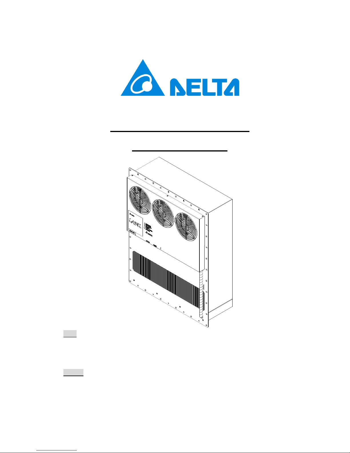
HEX150PC Heat Exchanger
Instruction Manual
USA
46101 Fremont Blvd, Fremont, CA 94538, U.S.A. TEL : 1-510-668-5100
FAX : 1-510-668-0680
Cabinet-Thermal-Solutions@deltaww.com
Taiwan
Delta Electronics, Inc.
252, Shang Ying Road, Kuei San District TEL : 886-(0)3-3591968
Taoyuan City 33341, Taiwan, R. O. C. FAX : 886-(0)3-3591991
Page 2

Table of contents
1. Version ......................................................................................................... 1
2. Description ................................................................................................... 1
2-1. General ................................................................................................ 1
2-2. Specification ....................................................................................... 1
2-3. Environmental condition ................................................................... 2
3. Installation ................................................................................................... 2
3-1. Outline drawing .................................................................................. 2
3-2. Mounting panel cutout and waterproof foam sticking .................... 3
4. Electrical specification ................................................................................ 3
4-1. Connection and LED indicator (on HEX panel) ................................ 3
4-2. Standalone control mode ................................................................... 5
5. Mechanical feature ...................................................................................... 6
5-1. Thermal path and Airflow baffle ....................................................... 6
5-2. Configuration ..................................................................................... 6
6. Maintenance and Replacement .................................................................. 7
6-1. Maintenance ....................................................................................... 7
6-2. Replacement ...................................................................................... 8
7. MTBF and Reliability ................................................................................... 8
7-1. MTBF................................................................................................... 8
7-2. Relibability ......................................................................................... 8
8. Safety ............................................................................................................ 9
9. Accessory .................................................................................................... 9
9-1. Power cable ........................................................................................ 9
9-2. Function cable ................................................................................... 9
10. General Safety and Warnings ................................................................... 9
Page 3
HEX150PC Heat Exchanger Instruction Manual
Page 1
1. Version
Rev. Description Drawn Approved Issue date
00 Issue spec. Nick Wang Adam Chen 2016/1/25
01 Add sectioni 10 Nick Wang Adam Chen 2016/6/10
2. Description
2-1 . General
Delta Heat Exchanger (HEX) is designed for direct air to air heat
exchange to remove heat from the cabinet.
The internal and the external air circulation loops of the HEX are
separated to prevent the introduction of dust, humidity and dirt. The fan on
the external air loop conforms to IP55 protection rating.
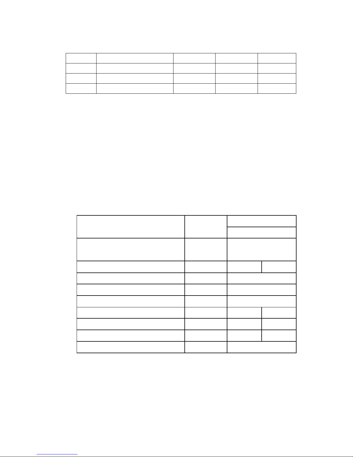
2-2 . Specification
Main feature Unit
Model Number
HEX150PC
Outline Dimension (H x W x D)
mm
(in)
690 x 550 x 242
(27 x 22 x 10)
Cooling Capacity (*Note 1)
W/K (W/℉)
100 (56) 135 (75)
Rated Voltage VDC 48
Rated Current (*Note 2) A 6.3
Operating Voltage Range VDC 40 - 60
Operating Current A 2.6 5.8
Operating Power Consumption W 125 279
Acoustic Noise at 1.5M (SPL) dB-A 65.0 73.0
Weight Kg (Lb) 20 (44)
* Note1 : The cooling capacity (W/K , W/°C or W/℉) is defined as Q/ (TI-TA)
Q : Heat dissipation (W) from inside of cabinet
TI : Return temperature of internal air circuit (K , °C or ℉)
TA : Ambient temperature of external air circuit (K , °C or ℉)
*Note 2 : Rated current is announcement of safety
Page 4
HEX150PC Heat Exchanger Instruction Manual
Page 2
2-3 . Environmental condition
Description Specification
Operating
-10°C ~ +65°C (-14°F ~ 149°F)
Storage
-40°C ~ +70°C (-40°F ~ 158°F)
Humidity
External air circuit: 0 ~ 100% RH
Ingress protection
(on external side)l
IEC60529 IP55 (NEMA 3)
GR-487 720hrs salt spray
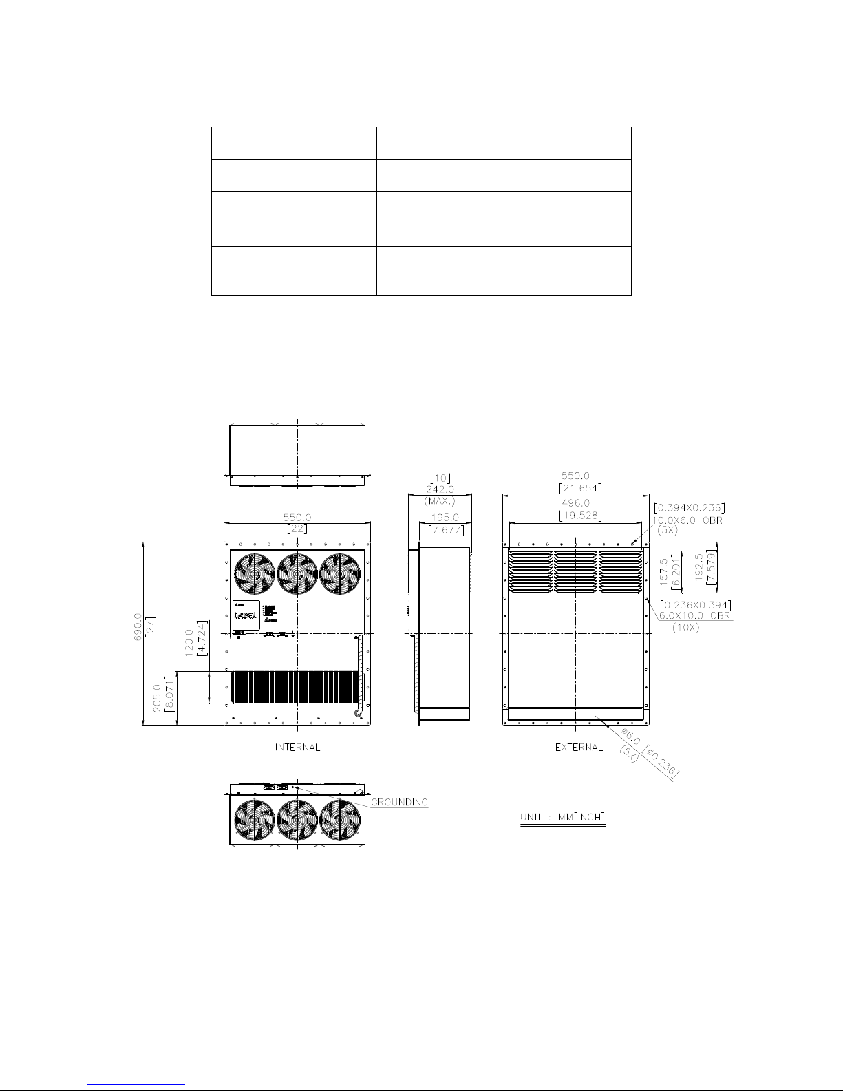
3. Installation
3-1 . Outline drawing
(1) Material : Aluminum sheet t=1.5mm
(2) Finish : Power paint , Color RAL7032
(3) Dimensional tolerance : ± 1mm [0.04”]
Page 5

HEX150PC Heat Exchanger Instruction Manual
Page 3
3-2 . Mounting panel cutout and waterproof foam sticking
:
:
4. Electrical specification
4-1. Connection and LED indicator (on HEX panel)
Power Connection
on panel plate : CVILUX 3W3CS0000100000
mate with : CVILUX 3W3CP0000100000
COMM connection
on panel plate : CVILUX CD5115PA100
mate with : CVILUX CD5115SA100
Page 6

HEX150PC Heat Exchanger Instruction Manual
Page 4
User can follow dry contact definition that is Normal Close (N.C.) to
detect abnormal status from pin 10 & pin 11
Definition N. C
Connection Pin 10 & Pin 11
Control board, NTC and fan are in
normal status
CLOSE
NTC resistance is over range such as
“open circuit” or “short circuit”
OPEN
Fan speed is lower than 50% of
definition or fan is locked
OPEN
Dry contact max. rating : 75VDC/50mA
LED indicator
INNER FAN / OUTER FAN / STATUS LEDs indicate fan and NTC
sensor status .
Depress "TEST" button to start auto-test of outer and inner fans
running from low to high speed. Turn off by depressing the “TEST” button
again .
INNER FAN
OUTER FAN STATUS
Normal GREEN
GREEN
GREEN
Failed* RED
RED
RED
Normal
(touch TEST / CLEAN)
Blinking
GREEN
Blinking
GREEN
N/A
Failed*
(touch TEST / CLEAN)
Blinking
RED
Blanking
RED
N/A
* FAN failed : Fan speed is lower than 50% of definition or fan is locked
* STATUS Failed : NTC resistance is over range such as “open circuit” or
“short circuit”
Page 7

HEX150PC Heat Exchanger Instruction Manual
Page 5
NTC temperature sensor
User can switch inner sensor (on control panel) or external
sensor (COMM port Pin7 & Pin8 ) via J13 connector on controller as
shown below to change sensor location .
4-2. Standalone control mode
HEX can detect ambient temperature to control cooling capacity .
Internal fan and external fan speed default settings are shown below
Cooling capacity (W/K) vs. Temperature
Inner fan speed vs. Temperature Outer fan speed vs. Temperature
Page 8

HEX150PC Heat Exchanger Instruction Manual
Page 6
5. Mechanical feature
5-1 . Thermal path and Airflow baffle
With forced convection using the axial fan, warm air generated by the
equipment will be blown into the internal return opening and pass though
the HEX, then flow out from internal supply opening. The air supply of the
cold air will be used to cool down the system; On the opposite side, cooler
air from the surrounding environment will be drawn in from the external air
inlet side , and push the heat of the HEX out from the external air exhaust
side. The thermal exchange path is shown in the figure below .
5-2 . Configuration
Item Q'ty
Description
1 1 Chassis assy
2 6 Fan guard
3 1 Controller
4 3 Internal fan
5 3 External fan
6 1 Heat exchange CORE
7 1 Internal plate assy
8 1 External plate assy
Page 9

HEX150PC Heat Exchanger Instruction Manual
Page 7
6. Maintenance and Replacement
Be sure to SHUT DOWN the power before proceeding with any
maintenance or component replacement .
6-1. Maintenance
Monthly
Use brush and low pressure air to remove dust or any debris on both
internal/external air inlet and air outlet opening .
Quarterly
Follow below maintenance sequence
Internal loop maintenance :
* The maintenance is from the internal side .
* Use screw driver to remove screw on upper
portion of chassis assy (Item 1) .
* Disassemble the internal plate assy (Item 7) and disconnect
fan from controller (Item 3) . Note the connection location .
* Use brush and low pressure air to remove dust on
internal plate assy (Item 7) , internal fan (item 4) and heat
exchange core opening .
* Hold internal plate assy (Item 7) and connect fan to controller
(Item 3) .
* Re-attach internal plate assy (Item 7) and use screw driver to
secure screw with chassis assy (Item 1) .
External loop maintenance :
* The maintenance is from the external side .
* Use screw driver to remove the screw on bottom portion of
chassis assy (Item 1) .
* Disassemble and hold external plate assy (Item 8) , no need
to disconnect external fan .
* Use brush and low pressure air to remove dust on external
plate assy (Item 8) , external fan (Item 5) and heat exchange
CORE opening .
* Re-attach external plate assy back (Item 8) and use screw
driver to secure screw with chassis assy (Item 1) .
Page 10

HEX150PC Heat Exchanger Instruction Manual
Page 8
Test
Power on and depress “TEST” button on panel to proceed with
auto test . Follow LED status to check that HEX has resumed to normal
function after maintenance .
6-2. Replacement
Delta HEX is designed with dry contact alarm output and LED
indicator on panel shown below to describe abnormal situation .
Refer to Section 4-1 for checking abnormal part is internal fan ,
external fan or controller for abnormalities .
In cases of parts abnormality , Delta will follow the reading and submit
spare part(s) below for replacement .
Internal fan P/N : AFB1548EH-BJ51
External fan P/N : AFB1548VH-CA18
Controller P/N : HEX150PC-000C
User can then refer to maintaince sequence on previous page , or
request Delta authorized support for assistance .
7. MTBF and Reliability
7-1. MTBF
L10 Fan life is expected to be minimum 80,000 hours continuous
operation at 40°C with 15 ~ 65%RH .@ label rated voltage
7-2. Relibability
Test item Condition
High temperature IEC 60068-2-2
Low temperature IEC 60068-2-1
High temp. / High humidity IEC 60068-2-14 TEST Nb
Temperature cycle IEC 60068-2-3
Vibration ETSI 300 019-1-4 CLASS 4.1
Ingress protection
(External side)
IEC 60529 IP55 (NEMA 3)
GR-487 720hrs salt spray
Package bump IEC 60068-2-29
Page 11

HEX150PC Heat Exchanger Instruction Manual
Page 9
8. Safety
9. Accessory
9-1. Power cable
9-2. Function cable
10. General Safety and Warnings
* Some electronic parts have a high operating temperature .
Use caution at all times.
* Incorrect installation may cause damage and/or injury.
* Installation and maintenance should be performed only by qualified
personnel . Use caution at all times.
* Ensure the grounding wire is connected before powering on the system.
* Ensure the cover and the mounting hardware are secure upon installation.
* All the cables connected to the unit must confirm to UL standards.
 Loading...