

Page 1

eZV-440
Application Guide
Edition 2.6
Page 2

Table of Contents
Copyright 8
About the eZV-440 9
About This Guide 9
Upgrading Firmware 9
Object Restriction Settings (ORS) 10
ORS Troubleshooting 10
About the enteliZONE ORCAview Configuration Graphic 11
Downloading the ORCAview Configuration Graphic 11
Installing the ORCAview Configuration Graphic 11
Opening the ORCAview Configuration Graphic 11
Method 1 (Recommended) 12
Method 2 12
Working with the ORCAview Configuration Graphic 12
Selecting Between Multiple Controllers 12
Save to Flash, Save to PC and Load from PC 13
Shortcuts 13
Configurable and Programmable enteliZONE Controllers 14
Differences Between Configurable and Programmable enteliZONE Controllers 14
LINKnet Devices 14
Data Exchange 15
Alarming 15
Trend Logs 16
Programming 17
eZV-440 Application Guide
Edition 2.6
Page 1 of 84
Page 3

enOcean Integration (firmware 2.2 and higher) 18
Upgrade to Fully Programmable Using Flash Loader (firmware 2.2 and higher) 18
VAV/VVT Programmable Objects 19
VAV/VVT Programmable Objects 19
Relationship Between Algorithm Unit Modules 20
General Tab 22
What is the General Tab? 22
Device Information 22
Network Settings 23
Global Settings 24
Local Inputs Tab 26
Setting Up a Hardwired Temperature Sensor 26
Set Up a Hardwired Temperature Sensor 26
Setting Up a Hardwired Occupancy Input 27
Set Up a Hardwired Occupancy Input 28
Setting Up a Hardwired CO2 Sensor 29
Setting Up Other Supporting Inputs 30
Set Up an Input 30
Setting Up an Airflow Sensor 31
Introduction 31
Setting Up Damper Feedback 31
Local Outputs Tab 33
Setting Up a VAV/VVT Output 33
Introduction 33
Set Up a VAV or VVT Output 33
Page 2 of 84 eZV-440 Application Guide
Edition 2.6
Page 4

Setting Up a Fan Output 34
Set Up a Fan Output 34
Setting Up Other Outputs 36
Set Up an Output 36
Setting Up a Damper Output 37
Set Up a Damper Output 37
LINKnet I/O Tab 38
Configuring an eZNS-T100 Network Sensor 38
Set Up the Temperature Sensor 38
Set Up the Humidity Sensor 39
Set Up the CO2 Sensor 39
Set Up the Occupancy Sensor 39
Assign Functions to the Buttons and Slider 40
Set Up the LCD Display 40
Assigning Buttons and Slider Elements on eZNS-T100 Network Sensor 41
Introduction 41
Set Up the Buttons and Slider Elements 43
Configuring DNS-24L Network Sensor 46
Introduction 46
Set Up the Temperature Sensor 46
Set Up the Humidity Sensor 46
Set Up the CO2 Sensor 47
Set Up the Occupancy Sensor 47
Assign Functions to the Buttons 47
Set Up the LCD Display 47
eZV-440 Application Guide
Edition 2.6
Page 3 of 84
Page 5

Assigning Buttons on DNS-24L Network Sensor 47
Introduction 47
Set Up the Button Elements 48
Setpoints Tab 50
What is the Setpoints Tab? 50
Space Temperature Setpoints 50
Occupied Heating Setpoint (OccHeatingSetpoint) 50
Unoccupied Heating Setpoint (UnOccHeatingSetpoint) 50
Occupied Cooling Setpoint (OccCoolingSetpoint) 50
Unoccupied Cooling Setpoint (UnOccCoolingSetpoint) 50
Occupied Setpoint Offset Range (OccSetpointOffsetRange) 50
Eco Mode Setback (EcoModeSetBack) 51
Standby Setback (StandbySetback) 51
Discharge Air Temperature Limiting Setpoint Differentials 51
Discharge Air Temperature High Limit Setpoint Differential (DATHiLimitSetpointDiff) 51
Discharge Air Temperature Low Limit Setpoint Differential (DATLowLimitSetpointDiff) 51
VAV/VVT Setpoints 51
VAV Box Size (VAVBoxSize) 51
Flow Factor (FlowFactor) 52
Airflow Failure Setpoint (AirflowFailureSetpoint) 52
CoolingMinimum 52
CoolingMaximum 52
HeatingMinimum 52
HeatingMaximum 52
StandbyMinimum 52
Page 4 of 84 eZV-440 Application Guide
Edition 2.6
Page 6

Controllers Tab 53
What is the Controllers Tab? 53
Controller Type 53
Proportional Band 53
Deadband 53
Integral Rate 53
Reset Band 53
Outdoor Air Temperature Heating Lockout Setpoint (OAT Htg Lockout) 54
Heating Demand Limit (Htg Demand Limit) 54
Outdoor Air Temperature Cooling Lockout Setpoint (OAT Clg Lockout) 54
Cooling Demand Limit (Clg Demand Limit) 54
Air Balancing Tab 55
What is the Air Balancing Tab? 55
Variable Air Volume (VAV) System Commissioning 55
Air Balancing 55
To auto zero-calibrate the airflow sensor: 56
To calibrate the airflow factor: 56
Check Duct Heater Airflow Safety 57
enteliZONE Sequence of Operations 58
Introduction 58
Setpoint Control 58
Setpoint Range Limits 58
Occupancy Modes 59
Switching Between Occupancy Modes 60
Setpoints and Occupancy Modes 62
eZV-440 Application Guide
Edition 2.6
Page 5 of 84
Page 7

Heating and Cooling (VAV) 63
Time-Proportional Heating and Cooling 64
Discharge Air Temperature 65
Fan (VAV) 65
Single Speed Parallel Fan Sequence 65
Modulating Speed Parallel Fan Sequence 66
Single Speed Series Fan Sequence 67
Modulating Speed Series Fan Sequence 67
Damper and Airflow Setpoint Control 67
Airflow Setpoints 67
Air Balancing 69
Demand Control Ventilation 70
Open Window Detection 70
enteliZONE Database Configuration Objects 71
Introduction 71
Input Configuration Objects 71
Occupancy Configuration Objects 73
Output Configuration Objects 74
Setpoint Configuration Objects 75
Device Instance/ BACnet Address Object 78
Control Types 79
What are Control Types? 79
Open Source Licensing 81
lwIP 81
ST Microelectronics 82
Page 6 of 84 eZV-440 Application Guide
Edition 2.6
Page 8

Document Revision History 83
eZV-440 Application Guide
Edition 2.6
Page 7 of 84
Page 9

Copyright
Copyright
Copyright © Delta Controls Inc. All rights reserved.
No part of this document may be reproduced, transmitted, transcribed, stored in a retrieval system,
or translated into any language (natural or computer), in any form or by any means, without the
prior written permission of Delta Controls Inc.
Limited permission is granted to reproduce documents released in Adobe® Portable Document
Format (PDF) electronic format in paper format. Documents released in PDF electronic format
may be printed by end-users for their own use using a printer such as an inkjet or laser device.
Authorized distributors of Delta Controls Inc. products (Delta Partners) may print PDF documents
for their own internal use or for use by their customers. Authorized Delta Partners may engage a
printing or copying company to produce copies of released PDF documents with the prior written
permission of Delta Controls Inc.
Information in this document is subject to change without notice and does not represent a
commitment to past versions of this document on the part of Delta Controls Inc. Delta Controls Inc.
may make improvements and/or changes to this document /the associated software/or associated
hardware at any time.
BACspec, BACstat, the Delta logo, ORCAview, ORCAweb, Earthright, enteliWEB, enteliBUS,
enteliMESH, enteliTOUCH, enteliZONE, enteliSTAT, and Virtual Stat are registered trademarks
of Delta Controls Inc.
All other trademarks are the property of their respective owners.
Document edition: 2.6
Published on Wednesday, August 23, 2017
Page 8 of 84 eZV-440 Application Guide
Edition 2.6
Page 10

About the eZV-440
The eZV-440 and eZVP-440 controllers are native BACnet controllers optimized for fan coil
applications. It features line voltage power input with a built-in 24 VAC inverter and line voltage
rated relays eliminating the need for a local control transformer or external relays to switch the fan.
The controller is also designed to be compatible with Delta Controls’ eZNS and DNS-24L network
sensors.
The eZV-440 comes preloaded with algorithms which you configure using a configuration graphic
to match your site’s needs. There are 2 types of eZV-440 controllers: both the configurable (eZV)
and programmable (eZVP) models use the configuration graphic for setup but only the
programmable controller allows you to overwrite the default sequences with General Control
Language (GCL) programming.
You can use ORCAview 3.40R3 and higher or enteliWEB 4.1 and higher to access the
configuration graphic.
About This Guide
This application guide introduces the controller and describes the differences between the
configurable and programmable models. The guide also shows you how to use the configuration
graphic in ORCAview 3.40 R3 and higher to set up your eZV-440 controller. The product name
eZV-440 in this guide refers to both the configurable and programmable models unless stated
otherwise.
The ORCAview configuration graphic version referenced in this guide is B-169041.1.
For help with the eZV-440 configuration page in enteliWEB 4.3 and higher, go to the online help in
enteliWEB. enteliWEB users require the applicable object permissions to change the settings on
the configuration page.
The installation guide for the eZV-440 can be found on the eZV-440 product web page on
the Delta Controls Support web site.
Upgrading Firmware
See the release notes of the firmware version you are upgrading to for more information.
Release notes are available on the Delta Controls Support web site
eZV-440 Application Guide
Edition 2.6
Page 9 of 84
Page 11

About the eZV-440
Object Restriction Settings (ORS)
The Object Restriction Settings (ORS) object allows the user to limit which database objects can be
viewed and edited. This is useful for hiding configuration settings which are not used in day-to-day
operation, to ensure a user cannot inadvertently change the configuration after initial system
commissioning. enteliZONE controllers support permission options of visible, read and write.
However, enteliZONE controllers do not support create or delete permissions as enteliZONE has a
fixed database structure where objects are editable but cannot be created or deleted. enteliZONE
controllers also do not support multiple ORS objects with temporary unlock permissions.
ORS security is turned on and off by locking and unlocking the controller. The ORS is unlocked in
the default database configuration. It must be unlocked in order to configure the controller. If the
controller is in a locked state, a message is displayed asking the user to unlock the controller.
To unlock the controller in ORCAview:
1. In the Navigator tree, right-click on the enteliZONE controller and point to Object Security
and then click Unlock.
2. Enter the unlock username and password. The default username is DELTA and the
password is login.
ORS Troubleshooting
If the controller time does not match the OWS time, the controller cannot be unlocked. To update
the controller time in ORCAview, on the Tools Menu, click Set Controller Time.
Without the correct username and password there is no way to unlock the controller. If the correct
username and password is unavailable, reload a copy of the default database into the controller,
this restores access to the controller, using the default username and password, however any
previous configuration changes will be lost.
Page 10 of 84 eZV-440 Application Guide
Edition 2.6
Page 12
About the enteliZONE ORCAview Configuration Graphic
The enteliZONE controller configuration graphic in ORCAview provides a user-friendly interface to
configure the controller’s algorithm and its corresponding objects and IO points. Each time a
change is made to a field or option,ORCAview updates the corresponding object references. The
topic enteliZONE Database Configuration Objects lists the fields and options, and their object
references.
In enteliWEB, the configuration page is available as a tab on the Object List page.
Downloading the ORCAview Configuration Graphic
You can download the configuration graphic from the enteliZONE controller product web page on
the Delta Controls Support web site and install it on your operator workstation.
Installing the ORCAview Configuration Graphic
To install the configuration graphic in ORCAview:
1. On your operator workstation, go to the graphic folder C:\Users\Public\Delta
Controls\3.40\Sites\<site name>\Graphics. The site name refers to the site where the
enteliZONE controller you are configuring resides.
2. Copy and paste the configuration graphic zip file into the Graphics folder.
3. Unzip the file.
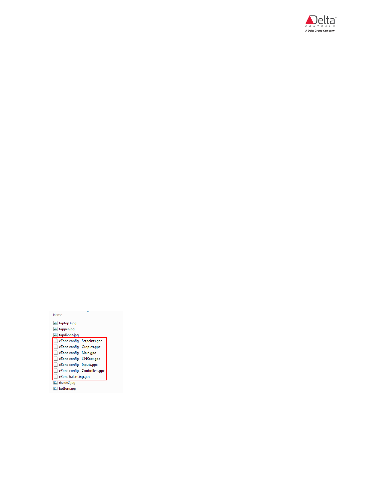
There are 7 configuration (.gpc) files associated with the enteliZONE controller. Each file
corresponds to a tab on the configuration graphic. The balancing file is not enabled on the eZFC424R4-24 or eZ-440R4-230 controller.
Opening the ORCAview Configuration Graphic
There are 2 ways to open the configuration graphic in ORCAview. Make sure the configuration
graphic is installed on your operator workstation before attempting any of these steps.
eZV-440 Application Guide
Edition 2.6
Page 11 of 84
Page 13

About the enteliZONE ORCAview Configuration Graphic
Method 1 (Recommended)
1. In the left window of the ORCAview navigator, right-click on the enteliZONE controller you
want to configure and click Open.
If this is your first time using the configuration graphic, the DEV object dialog opens.
2. On the Configuration tab, click and browse to the graphics folder and select the Main.gpc file
for the enteliZONE controller. Click OK.
3. In the left window of the ORCAview navigator, right-click on the enteliZONE controller again.
Click Open. Because you have set it up in step 2, the configuration graphic window should
open and will open this way each time you select Open from the right-click menu.
Right-clicking does not work if you have changed the name of the configuration
graphic file or if the Controller Graphic field in the Device object (in the controller
database) has been edited.
Method 2
1. In the left window of the ORCAview navigator, open the Graphics folder and double-click on
one of the configuration files. A new graphic window opens. You can access all the
configuration files from this window.
2. In the numerical field at the top of the window, enter the BACnet address of the enteliZONE
controller you want to configure and click Connect.
Working with the ORCAview Configuration Graphic
This graphic is interactive and dynamic in real-time. When you select an option in a field, other fields
and options are displayed in response to the initial option selected. What this also means is that any
changes made to the fields are saved and applied instantly.
Selecting Between Multiple Controllers
If you have multiple enteliZONE controllers of the same kind on the same network, instead of
opening the configuration graphic individually for each controller in the ORCAview navigator, you
can switch between controllers within the configuration graphic.
When you switch between controllers, any changes made in a previous session will be
saved automatically before you switch to the next controller.
Page 12 of 84 eZV-440 Application Guide
Edition 2.6
Page 14
To select between multiple controllers:
In the numerical field at the top of the window, enter the BACnet address of the enteliZONE
controller you want to configure and click Connect.
Save to Flash, Save to PC and Load from PC
These buttons are displayed at the top of the configuration graphic dialog. They minimize the need
to switch between the configuration graphic and the ORCAview Navigator when you are working
with multiple controllers.
The Save to Flash button is used to save the controller database to the controller’s flash memory.
The Save to PC button is used to save the controller database .pdb file to your computer.
The Load from PC button is used to load a controller database .pdb file from your computer onto
the enteliZONE controller.
Both Save to PC and Load from PC allow you to save your configuration graphic settings and copy
them onto multiple enteliZONE controllers using ORCAview.
Shortcuts
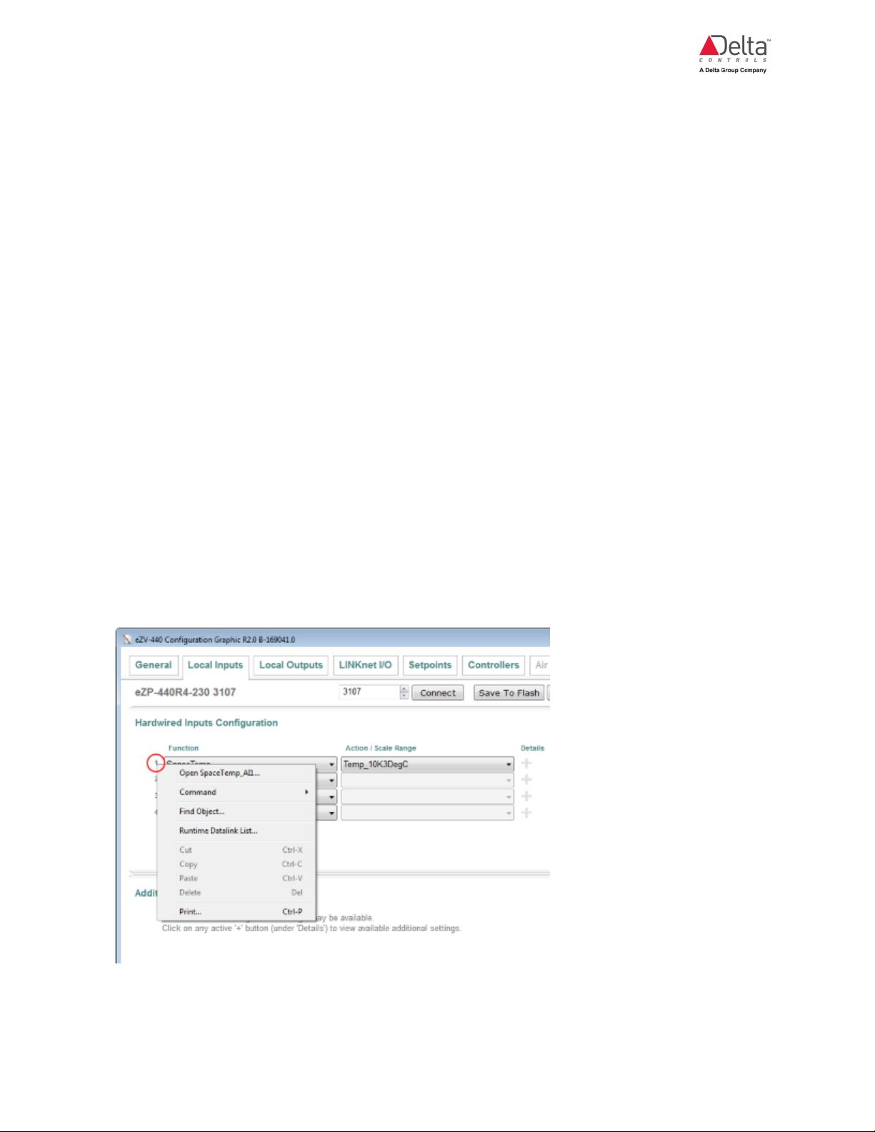
There is a quick way to open the ORCAview object dialogs by right-clicking on the configured input
and output numbers in the configuration graphic.
In the example below, when you right-click on the number 1 and select Open SpaceTemp_AI1,
the AI1 object dialog opens onscreen.
eZV-440 Application Guide
Edition 2.6
Page 13 of 84
Page 15

Configurable and Programmable enteliZONE Controllers
Configurable and Programmable enteliZONE Controllers
Differences Between Configurable and Programmable enteliZONE Controllers
This topic describes the main differences between these 2 types of controllers.
Using the ORCAview or enteliWEB configuration page, variables and setpoints are entered into
the algorithm and written to the appropriate preset objects (100 to 199 range, 1000+ range for
LINKnet device configuration) in the factory controller database.
In the configurable type of controllers, there are no program (PG) objects.
In the programmable controllers, even though it is recommended that you use the configuration
page to set up your programmable controller, local programming can be used to overwrite the
algorithm by writing to the objects in the 800 to 899 range.
There is a limit to the number of specific object types in these controllers. The number limits are
summarized in the table below. You cannot exceed this number by creating any new objects.
Object Type Configurable Programmable
LINKnet objects (LNK) 1 4
Event objects (EV)
Trend Logs (TL) 4 8
Programs (PG) 0 3
Gateway Translation objects (GWT)
(firmware 2.2 and higher)
For a complete list of enteliZONE supported object types and the number of instances allowed for
each object, go to the enteliZONE overview page on the Delta Controls Support web site.
LINKnet Devices
Configurable controllers can only connect to 1 LINKnet device at a time. This LINKnet device has to
have a device address of "1" in order for it to work with the controller algorithm. Multiple LINKnet
devices (up to 4) are only supported by the programmable controllers.
LCD and LINKnet objects are located on the enteliZONE controller and are numbered LCDx001
and LNKx001 respectively where x is the network sensor’s device address.
0 5
0 4
enteliZONE controllers only support eZNS and BACstat LINKnet network sensors. Other LINKnet
devices like Delta Field Modules (DFM) are not supported.
Page 14 of 84 eZV-440 Application Guide
Edition 2.6
Page 16

Data Exchange
This section describes how the enteliZONE controllers accept and initiate data exchanges in the
network.
The enteliZONE controller accepts these data exchange requests:
l Poll. The default data exchange type set up in the Data Exchange Settings object (DES) is
Poll. The poll interval can be adjusted in the DES object, at a recommended minimum of 1
second per MS/TP device on a segment.
l Change of Value (Confirmed and Unconfirmed). The enteliZONE controller is limited to
a maximum of 12 subscriptions (Delta Exchange Local or DEL objects).
The controller does not support the Optimized Broadcast and Broadcast Data Exchange request
types. If a controller attempts to subscribe using any of these exchange types, the exchange types
will fail and revert to polling.
The programmable controllers can initiate up to 12 data exchange polling requests (Delta
Exchange Remote or DER objects). Other types of Data Exchange initiating request types are not
supported.
The DES object for the controller lists the number of DER and DEL requests that are in use.
The controller supports Bulk Data Exchange (BDE) but is limited to 2 BDE objects. Each BDE
object can hold up to 12 tag and object entries on the object’s Transmit Entries tab.
For more information about Data Exchange types, go to the George Support knowledge base
article KBA 1813.
Alarming
The programmable controller supports up to 5 EV objects as well as intrinsic alarming on up to 5
input and output points (see below for more information about intrinsic alarming). These EV objects
support these alarm types:
Alarm
Description
Type
Change of
Used to monitor and alarm a binary value.
State
Command
Failure
Floating
Limit
Used when you have a binary value with feedback. An alarm is generated if
monitored values do not match the feedback value.
Used to alarm when an analog value varies more than a set limit from a variable
setpoint value.
eZV-440 Application Guide
Edition 2.6
Page 15 of 84
Page 17

Configurable and Programmable enteliZONE Controllers
Alarm
Description
Type
Out of
Used to alarm when an analog value varies outside of a set of fixed limits.
Range
The enteliZONE family of controllers does not support Change of Value or Change of Bitstring
alarm types.
Even though the configurable controller versions do not have EV objects, intrinsic alarming can be
enabled on input and output points, specifically analog input (AI), binary input (BI), analog output
(AO) and binary output (BO).
EV objects will send out auto generated messages to notify users about alarms. enteliZONE
controllers do not support alarm acknowledgments.
Custom alarm messages are supported by the following firmware versions:
l eZV-440 controller firmware version 2.1 and higher for EV objects only.
l eZFC-424R4-24 controller firmware version 2.2 and higher for EV objects only.
l eZ-440R4-230 controller firmware version 2.1 and higher for EV objects only.
For more information about how to set up an intrinsic alarm, see the webinar Intrinsic
Alarms in ORCA 3.40 on the Delta Controls support web site.
Trend Logs
A programmable enteliZONE controller supports up to 8 trend logs, 4 of which are user-defined.
The configurable controller version supports 4 trend log objects (TL1 to 4) which are pre configured
in the default database to monitor specific heating and cooling objects. However, all TLs can be
modified to monitor objects other than the default set object. You can also change the method of
data collection (Change of Value or polling) as well as the polling interval. However, fields that
display the maximum and total sample size are read-only.
It is not recommended to use Change of Value for objects that are expected to change at a rate
faster than every 5 seconds. TL objects have a 5-second record limit. Events that occur faster than
this record limit will result in “Log Enabled” or “Log Interrupted” entries that can be hard to interpret.
The default database TL objects are listed in the following table.
Trend Log Monitored Object
1 SpaceTemp (AV1)
2 CurrentHeatSetpoint (AV800)
Page 16 of 84 eZV-440 Application Guide
Edition 2.6
Page 18

Trend Log Monitored Object
3 CurrentCoolSetpoint (AV801)
4 HeatCoolLoad (AV802)
5 User-defined
6 User-defined
7 User-defined
8 User-defined
The enteliZONE trend logs also support Historian archiving. The enteliZONE controllers don’t
support buffer full notification events so make sure the Historian update interval is frequent enough
to avoid missing samples.
Programming
In the programmable controller, the 3 programs that exist alongside the configurable algorithm
allow you to either create your own custom algorithm or override portions of the configurable
algorithm to suit your needs. The maximum size of each program is 5 KB.
The programmable controller also allows you to create new I/O, AV, BV and MV objects in the 900999 range for use in your custom program.
Supported GCL+ Programming Functions, Statements and Operators
The Call Statement is not used in the programmable enteliZONE controllers. Unlike other
programmable Delta Controls controllers, the 3 programs in the programmable enteliZONE
controllers are automatically scanned. The scan rate is also designed to be a constant 10
scans/second.
A list of supported and unsupported GCL+ functions and statements for the enteliZONE
programmable controllers is recorded in KBA 2137 on the George Support web site. The
ORCAview and enteliWEB GCL editors are not aware of these limitations, so using an
unsupported function in an enteliZONE programmable controller will not register a syntax error in
these GCL editors.
Overwriting the Algorithm
You can overwrite the algorithm by programming specific objects numbered in the 800 range. For
example, if you want to change how the algorithm determines the occupancy state, you could write
your own GCL+ program to set the occupancy MV800 state.
Your program must write more frequently than every 5 seconds else the factory algorithm will
recapture control.
eZV-440 Application Guide
Edition 2.6
Page 17 of 84
Page 19

Configurable and Programmable enteliZONE Controllers
Click on a link below to find out more information about these programmable objects.
l VAV/VVT algorithm programmable objects
enOcean Integration (firmware 2.2 and higher)
Gateway Translation (GWT) and Gateway (GW) objects are available on the programmable
enteliZONE controllers so that you can integrate an enteliZONE programmable controller into an
enOcean wireless system using a CON-ENOC enOcean Gateway device.
For more information about how to configure the GWT objects, see the CON-ENOC Application
Guide on the CON-ENOC George Support product page.
Upgrade to Fully Programmable Using Flash Loader (firmware 2.2 and higher)
Delta Controls Flash Loader (Version 3.40 R4) can be used to upgrade controllers from
configurable to fully programmable versions. Flash Loader is part of the ORCAview suite of
software.
Flash Loader connects to and upgrades 1 controller at a time over the BACnet Ethernet network.
This upgrade requires 3 Flash credits on a Flash Loader key. Go to the Flash Loader page
on the George Support web site for more information.
1. Insert a Flash Loader key with sufficient credits into a USB port on your workstation.
2. Download the .FLS upgrade file from the George Support web site onto your workstation.
Save the file in the Flash Loader folder that was created when you installed Flash Loader,
like C:\Program Files(x86)\ Delta Controls\3.40\Flash Loader.
3. Back up the controller database by saving it. Flash Loader does not save the database
before the upgrade.
4. Open Flash Loader version 3.40 R4 on your workstation.
5. In the Filename dropdown list, select the upgrade file on your workstation.
For example, for firmware 2.1, the file name will be eZONE R2.1 B-xxxxxx.fls, where xxxxxx
is the build number.
6. Click the Enables Features box to check it. The eZONE section is displayed.
7. Click the Settings button.
1. In the Protocol dropdown list, select BACnet Network.
2. In the Adapter dropdown list, select the Ethernet adapter that connects the
workstation to the controller network.
Page 18 of 84 eZV-440 Application Guide
Edition 2.6
Page 20

3. Leave the Password field blank unless a password is defined in the Flash Loader
Password field on the Configuration tab of the controller’s DEV object.
4. Click OK to save changes made in the Settings window.
8. In the device Address field, enter the BACnet device address of the controller you want to
flash. This is the address displayed next to the controller in ORCAview Navigator.
9. In the eZONE section, click the Upgrade to Programmable box to check it.
10. Click Add Features.
Flash Loader transmits the new firmware to the controller. The Status and Progress fields in
the Flash Loader window display the status of the transmission.
11. When the upgrade is complete, the Status field displays an Update Complete message.
12. Close the Flash Loader program.
VAV/VVT Programmable Objects
VAV/VVT Programmable Objects
The following table displays all the programmable objects in the VAV/VVT enteliZONE algorithm.
For more information about programmable objects, go to the topic about programmable
controllers.
Algorithm Unit
Unit Module's Function Programmable Object
Module
Airflow Setpoint
Maintains the airflow setpoint in the duct. AV830 AirflowSetpoint
Manager
Box Mode
Controls “box mode” by monitoring the room
temperature and the inlet air temperature.
MV801
VAVDuct1BoxMode
For more information about box mode, see
the Heating and Cooling (VAV) sequence of
operation.
Controller Man-
ager
Cooling Stage
Manager
Determines the heating and cooling load on
the system.
Controls the VAV/VVT cooling sequence.
AV802 HeatCoolLoad
AV808 AirflowDemand
AV810 Fan1
Damper Manager Controls the damper position. AV832 DamperCmd
eZV-440 Application Guide
Edition 2.6
Page 19 of 84
Page 21

Configurable and Programmable enteliZONE Controllers
Algorithm Unit
Module
Duct Status Man-
ager
Flow Loop Man-
ager
Heat Stage Man-
ager
Occupancy Man-
ager
Temperature Set-
point Manager
Unit Module's Function Programmable Object
Determines if there is enough duct air for
BV800 AirflowStatus
heating and cooling.
Controls airflow through the damper. AV831 Damper-
Demand
Controls heating sequences of operations.
AV808 AirflowDemand
AV803 Heat1
AV804 Heat2
AV805 Heat3
AV810 Fan1
Determines the occupancy mode in the
space at any time.
Controls the active heating and cooling set-
points in the space.
MV800 Occu-
pancyMode
AV800
CurrentHeatingSetpoint
Demand Control
Ventilation Man-
ager
Controls the CO2 levels in the space.
See the Demand Control Ventilation
sequence of operation for more information.
Relationship Between Algorithm Unit Modules
The PDF displays the relationships between unit modules.
AV801
CurrentCoolingSetpoint
AV813
DemandCtrlVent
Page 20 of 84 eZV-440 Application Guide
Edition 2.6
Page 22
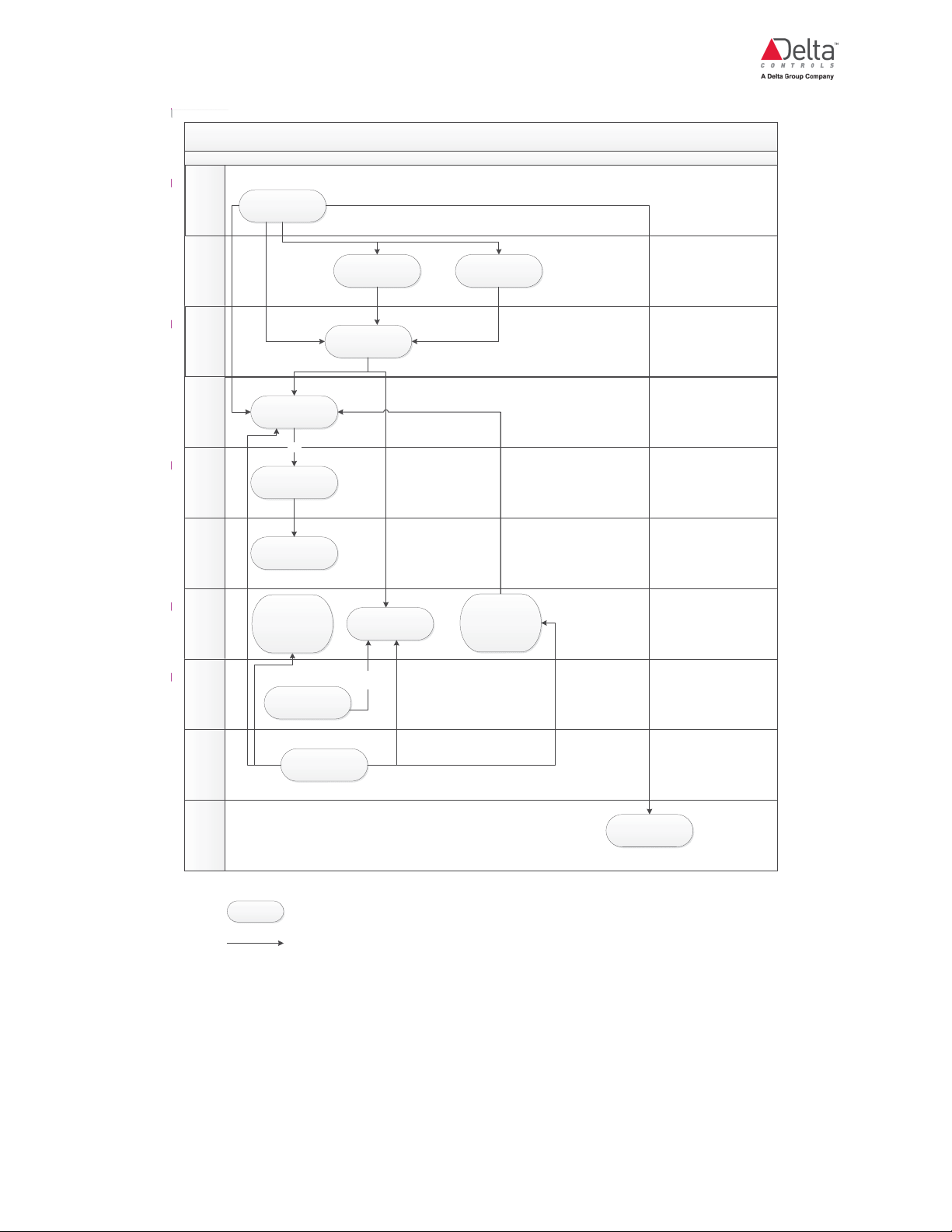
enteliZONE VAV Algorithm Flowchart
Temp Setpoint
Manager
Occupancy
Manager
Heat/Cool
Manager
Air Flow
Setpoint
Manager
Flow Loop
Manager
VAV/VVT
Damper
Manager
Heating Staging
Manager
Duct Status
Manager
Box Mode
Manager
Demand Control
Ventilation
MV800 Occupancy
Mode
AV800 CurrentHeating
Setpoint
AV801 CurrentCooling
Setpoint
AV802 HeatCool Load
AV830 Air Flow
Setpoint
AV831 Damper
Demand
VVT
AV832 DamperCmd
AV808 Air Flow
Demand
AV803 Heat1
AV804 Heat2
AV805 Heat3
BV800 Air Flow Status
Hydronic and
Electric Duct
MV801
VAVDuct1BoxMode
Point(s) in each algorithm manager box can be used to override the
algorithm manager
Relationship between points
AV810 Fan1
AV813 DemandCtrlVent
eZV-440 Application Guide
Edition 2.6
Page 21 of 84
Page 23

General Tab
General Tab
What is the General Tab?
The General tab on the enteliZONE controller configuration page is divided into 3 main sections.
The Device Information section contains basic controller information such as model number and
firmware version, and a device description field.
The Network Settings section contains the controller BACnet address, the network number as well
as the network speeds (baud rates).
In the Global Settings section, the options set here are applied to all tabs on the configuration page.
Device Information
The following fields are found in the Device Information section.
Field
Name
Name Displays the name of the controller as it appears in the Device Object.
Model
Name
Application
Version
Firmware
Version
Controller
Graphic
(ORCAview
only)
Device
Description
Description
Displays the controller's Delta Controls model number.
Displays the controller's algorithm version.
In the ORCAview configuration graphic, this field is called the Firmware
Version.
Displays the controller's firmware build number.
In the ORCAview configuration graphic, this field is called the Firmware Build.
Displays the configuration graphic file that opens every time you right-click on
the controller in the ORCAview navigator. You can also enter the name of a
dashboard graphic file and set it as the default graphic.
If you leave this field blank, the Device Object dialog opens instead.
You can enter and modify the controller's text description, up to 64 characters.
Page 22 of 84 eZV-440 Application Guide
Edition 2.6
Page 24

Network Settings
The following fields are found in the Network Settings section.
Field
Name
BACnet
Address
NFC
Password
DNA
Description
Displays the controller's BACnet address. This field is read-only when the DNA
box is checked. If you want to enter a new address, clear the DNA box.
Click here for more information about the BACnet address object.
Displays the password that secures access to the controller’s NFC chip. The
value range is 0 to 65535. The password is stored on the AV96 object.
The Device Password field on the Delta Controls mobile applications must match
the NFC password before any data can be written to the NFC chip.
Turns on or off Derived Network Addressing (DNA) automatic addressing. DNA
is turned on when the box is checked; the BACnet address also becomes readonly. To manually enter a new address, clear the DNA box.
Delta Controls products have the option to use DNA or Derived Network
Addressing, a system of organizing and configuring controllers in a network.
When DNA is enabled, addresses are automatically assigned to a device based
on the BACnet network type and the Delta Controls product type, so that a
device can work out-of-the-box without much set up.
NET1
Protocol
NET1
Speed
NET1
Number
NET1
MAC
Address
NET2
Protocol
NET2
Speed
Displays the network protocol currently enabled for the NET1 port. This is a read-
only field.
Displays the baud rate for the NET1 port. Any changes to the baud rate will be
applied immediately to all Delta Controls controllers in the network.
Displays the controller's BACnet network number.
Displays the controller’s network address typically set up by the controller’s DIP
switches.
Displays the network protocol currently enabled for the NET2 port. This is a read-
only field.
Displays the baud rate for the NET2 port. Any changes to the baud rate will be
applied immediately to all Delta Controls controllers in the network.
eZV-440 Application Guide
Edition 2.6
Page 23 of 84
Page 25
General Tab
Global Settings
The following fields are found in the Global Settings section.
Field Name Description
Application
Type
Temperature
Select the main HVAC system application for this controller. This determines
the algorithm that will be used for the controller.
The options for the eZV-440 are VAV-single duct, VVT and None.
The configurable controller has no functional state until you select an
algorithm.
In a fully programmable controller, when you select an algorithm, you can
override portions of the internal algorithm to suit your needs. See the section
in this guide about overwriting the algorithm. Select None if you want to
program a fully custom sequence of operations. When you select None, the
internal algorithms are disabled and all preconfigured algorithm I/O points and
variables are removed from the default database. Other object types, like AIC,
that were part of the algorithm can be used as is or reconfigured.
If you change an application type for another, the settings of the
previous application type will be deleted. You can save your
controller database before switching application types.
Displays the temperature units used by the controller.
Units
Airflow Units
Child
Controller
(enteliWEB
only)
Displays the airflow units used by the eZV-440 controller. Select between
CFM, l/s or m3/h.
In the configuration graphic, when VVT is selected as the application type, the
units are set to percentages which represent the damper min/max positions.
When VAV is selected as the application type, the AV124 to AV127 objects
and the air flow setpoint will use the units set up in the Airflow Units field.
If this controller reports to a parent controller, select this box. The child
controller polls these variables from its parent controller:
l HeatCoolLoad (AV802)
l OccupancyMode (MV800)
l DemandCtrlVent (AV813)
Page 24 of 84 eZV-440 Application Guide
Edition 2.6
Page 26

Field Name Description
Parent
Address
(enteliWEB
only)
Parent Child
Address
(ORCAview
only)
This field is enabled when the Child Controller box is checked. Enter the
parent's BACnet address in this field. If you are setting up a parent controller,
leave this field at its default zero value.
If the parent’s BACnet address changes in the future, you must manually
update this value to match the new address.
If this controller reports to a parent controller, enter the parent’s BACnet
address in this field. In all other cases, including setting up a parent controller,
leave this field at its default zero value.
If the parent’s BACnet address changes in the future, you must manually
update this value to match the new address.
The child controller polls these variables from its parent controller:
l HeatCoolLoad (AV802)
l OccupancyMode (MV800)
l DemandCtrlVent (AV813)
eZV-440 Application Guide
Edition 2.6
Page 25 of 84
Page 27

Local Inputs Tab
Local Inputs Tab
Setting Up a Hardwired Temperature Sensor
This topic describes how to set up a temperature sensor using the Local Inputs tab on the
configuration page.
Occupancy overrides can share the same input as the temperature sensor.
If you are setting up a LINKnet DNS-24L or eZNS network sensor to provide occupancy
input, use the LINKnet I/O tab on the configuration page.
Set Up a Hardwired Temperature Sensor
1. Wire your sensor to the controller's physical input.
2. Next to the input number that you've assigned to the sensor, in the Function field, select one
of the following options:
Function Select this option if you are using a:
DischargeAirTemp_ Duct temperature sensor that is located downstream from any
local heating or cooling stages that supply the air to that space.
InletAirTemp_ (VAV application type only) Duct temperature sensor that is
located upstream from local heating or cooling stages that
supply the air to that space.
SpaceTemp_ Space temperature sensor, or a network value from a DNS or
eZNS network sensor on LINKnet.
You can set up multiple SpaceTemp inputs and by default the
algorithm will calculate the average of all inputs and assign that
value to the AV1 object.
SpcTemp+
OccOvrdButton_
Space temperature sensor and the occupancy override push
button are wired into the same input.
This can be a normally open contact wired in parallel or a
normally closed contact wired in series with the temperature
sensor.
Page 26 of 84 eZV-440 Application Guide
Edition 2.6
Page 28

Function Select this option if you are using a:
SpcTemp+
OccToggleButton_
Space temperature sensor and the occupancy toggle push
button are wired into the same input.
This can be a normally open contact wired in parallel or a
normally closed contact wired in series with the temperature
sensor.
When setting up a temperature sensor, majority of the cases would require you to select
Temp_10K3DegC or Temp_10K3DegF as an option under Action/Scale, depending on
the temperature units set up on the General tab.
3. If you had selected the DischargeAirTemp_ option, in the additional settings, in the
DATHiLimitSetpointDiff and DATLowLimitSetpointDiff fields, enter the discharge air
temperature high limit and low limit setpoints differentials respectively.
4. (VAV application type only) If you had selected the InletAirTemp_ option, in the additional
settings, in the BoxChangeoverTempDiff field, enter the box changeover temperature
difference.
5. (enteliWEB only) The Input Name field displays the object's name. You can change this
name by clearing the field and entering a new name.
Multiple Space Temperature Inputs
You can set up multiple SpaceTemp inputs and by default the algorithm will calculate the
average of all inputs and assign that value to the AV1 object.
Setting Up a Hardwired Occupancy Input
This topic describes how to set up an occupancy input using the Local Inputs tab on the
configuration page.
Occupancy inputs can either be maintained-contact or momentary contact types. Occupancy
overrides can share the same input as the temperature sensor.
See the sequence of operations topic to learn more about occupancy modes in the algorithm.
If you are setting up a LINKnet DNS-24L or eZNS network sensor to provide occupancy
input, use the LINKnet I/O tab on the configuration page.
eZV-440 Application Guide
Edition 2.6
Page 27 of 84
Page 29

Local Inputs Tab
Set Up a Hardwired Occupancy Input
1. Next to the input number that you've assigned to the input, in the Function field, select one or
more of the following options:
Function Select this option if you are using a:
OccMotion_ Hardwired latching, momentary contact sensor type, or a
network sensor with an integrated motion sensor and want
to enable it for occupancy control.
OccMaintainedContact_ Any maintained contact device like a hotel keycard holder,
manual switch or mechanical time clock input.
OccOvrdButton_ Network sensor button as an occupancy override button.
When pushed during unoccupied mode it starts an
occupancy override timer. When an override has been
activated, pushing the button will extend the override time by
resetting the timer back to its max value.
During scheduled occupancy periods, you cannot switch
occupied to standby mode using the button. However if
occupancy is in standby mode, pressing the button will
switch the room back to occupied mode until the next
occupancy event change.
OccToggleButton_ Network sensor button to toggle between standby and
occupied modes during scheduled occupancy periods.
When pushed during unoccupied mode it starts an
occupancy override timer. When an override has been
activated, pushing the button again will cancel the override
and reset the override timer back to zero.
SpcTemp+
OccOvrdButton_
Space temperature sensor and the occupancy override
push button are wired into the same input.
This can be a normally open contact wired in parallel or a
normally closed contact wired in series with the temperature
sensor.
SpcTemp+
OccToggleButton_
Space temperature sensor and the occupancy toggle push
button are wired into the same input.
This can be a normally open contact wired in parallel or a
normally closed contact wired in series with the temperature
sensor.
In most cases Direct (contact closed = occupied) is the default action.
Page 28 of 84 eZV-440 Application Guide
Edition 2.6
Page 30

2. If you had selected the OccMotion_ option, in the additional settings, in the MotionOvrdTime
field, enter how long the occupancy override should last. This setting allows the use of
momentary contact style occupancy signals.
If you are using maintained-contact occupancy devices, enter zero in this field. In this case,
occupancy state is only based on contact position.
3. If you had selected any occupancy button options, in the additional settings, in the
PushButtonOvrdTime field, enter how long the button override should last.
4. (enteliWEB only) The Input Name field displays the object's name. You can change this
name by clearing the field and entering a new name.
With the OccToggleButton option, With the OccToggleButton option, it is recommended
to display the occupancy status on your network sensor. The occupancy status allows the
user to determine if a button press will start an override or cancel an active override.
Multiple Temp+Occ Inputs
You can set up multiple SpcTemp+OccOvrdButton and SpcTemp+OccToggleButton inputs
and by default the algorithm will calculate the average of all these temperature inputs. With multiple
occupancy inputs, the value will reflect the last value written.
Setting Up a Hardwired CO2 Sensor
This topic describes how to set up a carbon dioxide sensor using the Local Inputs tab on the
configuration page.
If you are setting up a LINKnet DNS-24L or eZNS network sensor to provide occupancy
input, use the LINKnet I/O tab on the configuration page.
Set Up a Hardwired CO2 Sensor
1. Wire your sensor to the controller's physical input.
2. Next to the input number that you've assigned to the input, in the Function field, select
SpaceCO2_. The default option in the Action/Scale column is CO2 0-2000ppm.
3. If you are using demand controlled ventilation with the CO2 sensors, in the additional
settings,
l In the DemandVentEnable field, select Enabled or On (enteliWEB only).
l In the CO2DemandVentSetpoint field, enter the CO2 setpoint value. Levels higher
than this setpoint will maintain the demand for ventilation.
eZV-440 Application Guide
Edition 2.6
Page 29 of 84
Page 31

Local Inputs Tab
4. In the additional settings, if you are using CO2 sensors to determine occupancy,
l (enteliWEB only) In the CO2 Occupancy On Setpoint field, enter the CO2 setpoint
value that will trigger an occupancy event. To disable CO2-based occupancy
detection, set this value to 2000 ppm.
l (enteliWEB only) In the CO2 Occupancy Off Setpoint field, enter the CO2 setpoint
value that will cancel an occupancy event.
5. (enteliWEB only) The Input Name field displays the object's name. You can change this
name by clearing the field and entering a new name.
For more information about demand control ventilation, see the Sequence of Operations topic.
For more information about using CO2 levels to trigger occupancy events, see the Sequence of
Operations topic.
Setting Up Other Supporting Inputs
This topic describes how to set up supporting inputs like fault and window monitoring using the
Local Inputs tab on the configuration page
Set Up an Input
1. Next to the input number that you've assigned to the device, in the Function field, select the
option that applies to your setup:
Function Select this option if you are using a:
AnalogMUX_ Creating an analog input that will be used for monitoring and
will not be used by the algorithm in the controller.
BinaryMUX_ Creating an binary input that will be used for monitoring and
will not be used by the algorithm in the controller.
WindowContact_ Setting up a window contact switch to detect open windows.
When an open window is detected, local heating or cooling
can be disabled as needed to save energy.
FilterStatus_ Adding a filter switch to detect if the fan coil filter is clean or
dirty.
FanStatus_ Adding a current or airflow switch that detects when the zone
supply fan is running.
Fault_ Creating an input to monitor the fault status of an equipment.
SpaceTempSetpoint_ Resistive slider or dial to control the space setpoint. The
resistance range must be within 0 to 20 kohms.
2. Select the associated action/scale option for the input.
Page 30 of 84 eZV-440 Application Guide
Edition 2.6
Page 32

3. If you had selected the SpaceTempSetpoint_ option to set up a resistive slider, in additional
settings, in the SetpointSliderMinResistance field, enter the minimum resistance of the
setpoint slider. In the SetpointSliderMaxResistance field, enter the maximum resistance
of the setpoint slider.
To enter the occupancy setpoint offset range for this resistive slider, go to the Setpoints tab
and enter the ± offset in the OccSetpointOffsetRange field.
4. (enteliWEB only) The Input Name field displays the object's name. You can change this
name by clearing the field and entering a new name.
For a list of input configuration software objects that correspond to each function, see the Input
Configuration Objects topic.
Setting Up an Airflow Sensor
Introduction
This topic describes how to set up an airflow pressure sensor on the eZV-440 controller on the
Local Inputs tab.
On the eZV-440 controller, physical input 6 is reserved for the onboard differential pressure sensor.
Set Up an Airflow Sensor
On the Local Inputs tab, next to input number 6, select VAVAirflow_ in the Function field.
(enteliWEB only) The Input Name field displays the object's name. You can change this name by
clearing the field and entering a new name.
Setting Up Damper Feedback
This topic describes how to set up damper position feedback using the Local Inputs tab on the
configuration page. The actuator must have a position feedback feature.
On the eZV-440 controller, the damper feedback signals should be configured on the controller
input 5.
Set Up Damper Feedback
1. Wire the actuator to the controller's physical input.
2. Next to the input number that you've assigned to the actuator, in the Function field, select
Damper1Feedback_. With the eZV-440 controller, you would use input number 5.
eZV-440 Application Guide
Edition 2.6
Page 31 of 84
Page 33

Local Inputs Tab
If a tristate output is assigned to a damper, the algorithm will use this feedback signal rather
than a calculated damper position based on runtime.
3. In the Action/Scale Range field, select the input scale range that matches your damper
feedback signal. If you do not select a scale range, the default scale range is assumed to be
zero to full scale 0 to 100%.
4. (enteliWEB only) The Input Name field displays the object's name. You can change this
name by clearing the field and entering a new name.
Page 32 of 84 eZV-440 Application Guide
Edition 2.6
Page 34

Local Outputs Tab
Setting Up a VAV/VVT Output
Introduction
This topic describes how to set up a VAV or VVT output on the Local Outputs tab of the enteliZONE
configuration page.
The eZV-440 controllers support the VAV and VVT algorithms, up to 3 heat stages (Heat1, Heat2
and Heat3).
For more information about the enteliZONE algorithm's sequence of operations, go to the
Sequence of operations topic.
Set Up a VAV or VVT Output
1. In the Function field, select the option that applies to your setup:
Function Select this option if you are:
ElectricDuct Setting up an electric duct unit.
ElectricBaseboard_ Setting up an electric baseboard heater.
HydronicDuct_ Setting up a ductal coil unit.
HydronicBaseboard_ Setting up a hydronic baseboard heater.
For a list of output configuration software objects that correspond to each function, see the
Output Configuration Objects topic.
2. In the Stage field, select the corresponding heat stage for the output device. If you are using
ORCAview,select the heat stage in the Output Stage field.
Start a new line for every additional heat stage.
3. In the Control Type field, select the method of control used on the output device signal.
The control types available in the drop-down list will change depending on the option that
was selected in the Function field and the physical output used to connect to the output
device. For more information about control types, see the Control Types topic.
4. In the Action field, choose between direct or reverse control.
5. (enteliWEB only) The Output Name field displays the object's name. You can change this
name by clearing the field and entering a new name.
6. Complete this task by setting up a fan output. You may also need to set up actuator damper
control.
eZV-440 Application Guide
Edition 2.6
Page 33 of 84
Page 35

Local Outputs Tab
Setting Up a Fan Output
This topic describes how to set up fan outputs on the Local Outputs tab of the enteliZONE
configuration page.
The enteliZONE controllers support up to 3 fan stages (Fan1, Fan2 and Fan3). Typically a 3-speed
fan stages uses Fan1, Fan2 and Fan3, and an ECM (Electronically Commutated Motor) fan uses
Fan1.
For more information about the enteliZONE algorithm's sequence of operations, go to the
Sequence of Operations topic.
Set Up a Fan Output
1. In the Function field, select the option that applies to your setup:
Function Select this option if you are:
SeriesFan_ Setting up a series fan in a single duct VAV.
ParallelFan_ Setting up a parallel fan in a single duct VAV.
ExhaustFan_ Setting up a exhaust fan based on occupancy.
For a list of output configuration software objects that correspond to each function, see the
Output Configuration Objects topic.
2. In the Stage field, select the corresponding fan stage for the output device. If you are using
ORCAview,select the heat stage in the Output Stage field.
Start a new line for every additional fan stage.
The ExhaustFan function defaults to OccInterlock or occupancy interlock.
3. In the Control Type field, select the method of control used on the output device signal.
The control types available in the drop-down list will change depending on the option that
was selected in the Function field and the physical output used to connect to the output
device. For more information about control types, see the Control Types topic.
ECM fans may require both an analog speed and a binary stop/start signal. For example, for
a modulating series VAV fan sequence that has both an analog speed and binary stop/start
signal, this is how you should set it up:
Function Output Stage Control Type
Start/Stop Output Series Fan_ Fan1_ Binary
Speed Output Series Fan_ Fan1_ Analog
4. In the Action field, choose between direct or reverse control.
Page 34 of 84 eZV-440 Application Guide
Edition 2.6
Page 36

5. (enteliWEB only) The Output Name field displays the object's name. You can change this
name by clearing the field and entering a new name.
6. In the additional settings available for some fan types:
l Constant Fan Modes. Allows you to select the occupancy mode in which the fan
runs constantly. If you are setting up a parallel fan, select Always Intermittent. In
occupancy modes where the fan is not running constantly, the algorithm assumes the
fan is running intermittently.
Always
Constant
Occupied/
Unoccupied
The fan always runs regardless of the heating or cooling
demand in the space.
The fan runs constantly during the occupied and unoccupied
override occupancy modes. Outside of these modes, the fan
runs intermittently.
Occupied/
Unoccupied
Override/
The fan runs constantly during the occupied, unoccupied
override occupancy and standby modes. Outside of these
modes, the fan runs intermittently.
Standby
Always
Intermittent
l Manual Fan Occupancy Interlock. This field is not applicable for VAV and VVT
The fan does not run constantly at all and only turns on when
heat is required.
systems.
l HeatxFanMin. These fields display the fan speeds that will run at a specific heat ("x" is
the stage number). For ductal heat outputs, with multi-speed fans, "1" is the default
value. With ECM fans, FanMinSpeed (see the section below) is the default value. "0"
is the default value for non-ductal outputs.
When you modify these values, the fan speed associated with that output is changed.
For example, if you enter “3” in Heat2FanMin, the fan will respond to the heating
demand at Heat 2 stage by increasing to fan speed 3.
l FanMinSpeed. The minimum supported supply fan speed. This field is enabled when
you select analog control type for supply fan with a default value of 20%. When you
select a binary control type for a single or multi-speed fan, this field displays the
minimum supported fan speed with a default value of 1 for ductal fans.
l FanMaxSpeed. The maximum supported supply fan speed. This field is enabled
when you select analog control type for supply fan with a default value of 100%. When
you select a binary control type for a single or multi-speed fan, this field displays the
maximum supported fan speed.
eZV-440 Application Guide
Edition 2.6
Page 35 of 84
Page 37

Local Outputs Tab
Setting Up Other Outputs
This topic describes how to set up supporting outputs like occupancy indicator on the Local Outputs
tab of the enteliZONE configuration page.
Set Up an Output
1. In the Function field, select the option that applies to your setup:
Function
Select this option if you
are:
OccIndicator_
Setting up an occupancy
output signal.
Any one of the following: ElectricBaseboard_,
HydronicBaseboard_
Controlling radiant heating
equipment.
GCL-controlled AO_* Creating a custom AO object.
GCL-controlled BO_* Creating a custom BO object.
* Available only with programmable enteliZONE models and only on output terminals that
support AO or BO objects.
For a list of output configuration software objects that correspond to each function, see the
Output Configuration Objects topic.
2. In the Stage field, for the radiant heating equipment, select the radiant heating equipment's
heat stage in the control sequence. If you are using ORCAview,select the heat stage in the
Output Stage field.
Function Stage or Output Stage
OccIndicator_ OccIndicator_ is the default
option.
Any one of the following: ElectricBaseboard_,
HydronicBaseboard_
Select one: Heat1_, Heat2_ or
Heat3_.
GCL-controlled AO_ None_ is the default option.
GCL-controlled BO_ None_ is the default option.
3. In the Control Type field, select the method of control used on the output device signal.
The control types available in the drop-down list will change depending on the option that
was selected in the Function field and the physical output used to connect to the output
device. For more information about control types, see the Control Types topic.
4. In the Action field, choose between direct or reverse control.
Page 36 of 84 eZV-440 Application Guide
Edition 2.6
Page 38

5. (enteliWEB only) The Output Name field displays the object's name. You can change this
name by clearing the field and entering a new name.
Setting Up a Damper Output
This topic describes how to set up damper outputs on the Local Outputs tab of the enteliZONE
configuration page.
Outputs 5 and 6 on the eZV-440 controllers are reserved for the actuator connector (1 Universal
Output, 1 TRIAC Output).
For more information about the enteliZONE algorithm's sequence of operations, go to the
Sequence of Operations topic.
Set Up a Damper Output
1. In the Function field, select the option that applies to your setup:
Function Select this option if you are:
VAV/VVT Damper_ Setting up a damper in a single duct VAV.
For a list of output configuration software objects that correspond to each function, see the
Output Configuration Objects topic.
2. In the Stage field, AirFlowDemand_ is selected automatically for VAV/VVT applications.
3. In the Control Type field, select the method of control used on the damper signal.
For more information about control types, see Control Types.
4. In the Action field, choose between direct or reverse control.
If you are using an analog actuator, in the Action field, choose between direct or reverse
control. For tri-state actuators, use the Control Type field to set the damper’s open and close
direction.
5. If you are setting up a VAV/VVT damper, in the additional settings, in the OP5-6Runtime
field, enter the amount of time it takes to move the damper from fully open to fully closed
positions.
6. If you are setting up a tri-state actuator with damper feedback, set up damper feedback on
the Local Inputs tab in the configuration page.
7. (enteliWEB only) The Output Name field displays the object's name. You can change this
name by clearing the field and entering a new name.
eZV-440 Application Guide
Edition 2.6
Page 37 of 84
Page 39

LINKnet I/O Tab
LINKnet I/O Tab
Configuring an eZNS-T100 Network Sensor
The enteliZONE controller is designed to work with the eZNS network sensor on a LINKnet
network.
This topic describes how to set up the eZNS network sensor's built-in components using the
LINKnet I/O tab on the enteliZONE configuration page.
Configurable controllers can only connect to 1 LINKnet device at a time. This LINKnet
device has to have a device address of "1" in order for it to work with the controller
algorithm. Multiple LINKnet devices (up to 4) are only supported by the programmable
controllers.
On the configuration page, the controller detects the network sensor that is connected to it and
displays only the fields that are relevant for that network sensor.
(enteliWEB only) If you do not have any network sensors online, you can still configure the settings
by selecting your network sensor and model from the Device Information field.
Red Box on LINKnet Tab
(enteliWEB only) When you switch between different network sensor models, active
settings that are not shared between network sensor models become outlined in red. You
need to select the None option to disable these fields.
Set Up the Temperature Sensor
1. In the Sensor Options section, next to Space Temperature sensor type, select the Function
option that is most appropriate for your needs:
Function Select this option if:
None The built-in temperature sensor on the eZNS sensor is not used.
SpaceTempControl
The built-in temperature sensor is used to control the space
temperature. An input object (AI1001) is created the sensor
value which will be used by the algorithm to control space
temperature.
MonitoringOnly
Page 38 of 84 eZV-440 Application Guide
Input object AI1001 created but its value will not be used by the
internal algorithm for space temperature control.
Edition 2.6
Page 40

Set Up the Humidity Sensor
1. In the Sensor Options section, next to Space Humidity sensor type, select the Function
option that is most appropriate for your needs:
Function Select this option if:
None The humidity sensor on the eZNS sensor is not used.
MonitoringOnly
The input object AI1003 is created for monitoring only.
Set Up the CO2 Sensor
1. In the Sensor Options section, next to Space CO2 sensor type, select the Function option
that is most appropriate for your needs:
Function Select this option if:
None The CO2 sensor on the eZNS sensor is not used.
DemandControlVentilation Demand controlled ventilation system is used with the
CO2 sensors.
MonitoringOnly
The input object AI1004 created but its value will not be
used by the internal algorithm for space CO2 control.
2. If you selected DemandControlVentilation, in the additional settings, in the
CO2DemandVentSetpoint field, enter the CO2 demand ventilation setpoint value.
3. If you are using CO2 levels to determine occupancy, in the additional settings,
(enteliWEB only) In the CO2 Occupancy On Setpoint field, enter the CO2 setpoint value that
will trigger an occupancy event. To disable CO2-based occupancy detection, set this value to
2000 ppm.
(enteliWEB only) In the CO2 Occupancy Off Setppoint field, enter the CO2 setpoint value
that will cancel an occupancy event.
Set Up the Occupancy Sensor
1. In the Sensor Options section, next to Occupancy Motion sensor type, select the Function
option that is most appropriate for your needs:
Function Select this option if:
None The occupancy sensor on the eZNS sensor is not used.
OccupancyDetection
The motion sensor on the eZNS network sensor is used to
detect occupancy.
eZV-440 Application Guide
Edition 2.6
Page 39 of 84
Page 41

LINKnet I/O Tab
Function Select this option if:
MonitoringOnly
Input object BI1005 created but its value will not be used by the
internal algorithm.
2. If you selected OccupancyDetection, in the additional settings, in the MotionOvrdTime field,
enter how long the occupancy override should last. This setting allows the use of momentary
contact style occupancy signals.
If you are using maintained-contact occupancy devices, enter zero in this field. In this case,
occupancy statue is only based on contact position.
Assign Functions to the Buttons and Slider
See Assigning Buttons and Slider Elements On eZNS-T100 Network Sensor.
Set Up the LCD Display
You can select which icons are displayed on the network sensor's LCD screen.
1. In the Display Options section, next to Occupancy, select the occupancy symbols you would
like displayed on the LCD screen.
Display
Select this option if you are setting up:
Option
NotDisplayed_ No occupancy status to be displayed.
ManInHouse_
Occupancy status: when a room is occupied, the man in a house icon
is displayed; when the room is unoccupied the icon changes so that
the man appears outside the house. When the occupancy sensor is
disabled, neither icon is displayed.
SunMoon_
Sun or Moon icon to be displayed. These icons can be used to show
day and night occupancy modes.
2. In the Display Setpoints, select how the setpoint of the current heating or cooling stage is
displayed on the LCD screen.
Display
Select this option if you are setting up:
Option
On Button
Press
The setpoint is displayed when the Temp Select, Temp Up or Temp
Down buttons are pressed.
Always The setpoint is always displayed on the LCD in occupied mode.
Page 40 of 84 eZV-440 Application Guide
Edition 2.6
Page 42

3. In the Temp Setpoint Type, select the type of setpoint displayed.
Temperature
Description
Setpoint Type
NotDisplayed_ Setpoint will not be displayed.
DualSetpoint_ Separate setpoints are used during heating mode and cooling mode.
SingleSetpoint_ The average of both the heating and cooling setpoints.
SetpointOffset_
The offset that you can enter to adjust the occupied heating and
cooling setpoints. The range available for this offset is determined by
the OccSetpointOffsetRange field on the Setpoints tab.
4. Complete each option to determine how the backlight should appear onscreen.
Backlight
Do the following:
Options
Backlight
Select a color from the list of available backlight colors.
Color
Backlight On
Intensity
Enter the desired backlight intensity when the screen is turned on with a
button press. 100% is the most intense.
Backlight Off
Intensity
Enter the desired backlight intensity when the network sensor is idle.
100% is the most intense.
Assigning Buttons and Slider Elements on eZNS-T100 Network Sensor
Introduction
The enteliZONE controller is designed to work with the eZNS network sensor on a LINKnet
network.
This topic describes how to assign specific functions to every button and slider element on the
eZNS network sensor using the LINKnet I/O tab on the enteliZONE configuration page.
There are as many as 95 button overlay combinations available for the eZNS network sensor.
Fortunately, all these combinations are based on this single layout which consists of 8 buttons and
the slider element:
eZV-440 Application Guide
Edition 2.6
Page 41 of 84
Page 43

LINKnet I/O Tab
Not all the buttons are used in every button overlay. In some cases, the slider element can be
converted into 2 additional up and down buttons, or omitted. In overlays where there are less than 8
buttons, button areas are merged together and counted as one (see the examples below).
(click to view larger version of image or images)
Page 42 of 84 eZV-440 Application Guide
Edition 2.6
Page 44

For more information about the button overlays, see the Button Overlay Selection Summary
document on George Support.
Set Up the Buttons and Slider Elements
The graphic supports all standard Delta button functions but other custom button behaviors require
GCL programming on a programmable controller. To designate a button to a custom button
behavior, select NotUsed_ from the Function field and refer to the button’s KeyPress property in
the GCL program.
eZV-440 Application Guide
Edition 2.6
Page 43 of 84
Page 45

LINKnet I/O Tab
1. On the LINKnet I/O tab, in the Button Options section, next to the button number that you
want to program, select one of the following functions that you want to assign to that button:
Function Select this option if you want to:
NotUsed_ Designate custom button behavior using GCL or if you want a
blank button.
EcoModeToggle_ Turns on the occupancy eco mode. In eco mode, the setpoints
are widened.
OccupancyOff_ Turn on the standby occupancy mode.
In the additional settings, in the PushButtonOvrdTime field, you
can enter how long the button override should last.
OccupancyOn_ Turn on the occupied mode.
In the additional settings, in the PushButtonOvrdTime field, you
can enter how long the button override should last.
OccupancyToggle_ Toggle between standby and occupied modes during scheduled
occupancy periods.
When pushed during unoccupied mode it starts an occupancy
override timer. When an override has been activated, pushing
the button again will cancel the override and reset the override
timer back to zero.
In the additional settings, in the PushButtonOvrdTime field, you
can enter how long the button override should last.
TempUnitsToggle_ Toggle between displaying the temperature in Celsius and the
temperature in Fahrenheit.
TempDown_ Decrease the temperature setpoint by 0.5 degrees with each
buttonpress. The 0.5 degree amount cannot be changed in the
enteliZONE configurable controller model. In the programmable
controller model, this setting can be overridden using GCL.
In the additional settings, in the OccSetpointOffsetReset field,
you can turn on the Occupancy Setpoint Offset Reset function*.
Page 44 of 84 eZV-440 Application Guide
Edition 2.6
Page 46

Function Select this option if you want to:
TempUp_ Increase the temperature setpoint by 0.5 degrees with each
buttonpress. The 0.5 degree amount cannot be changed in the
enteliZONE configurable controller model. In the programmable
controller model, this setting can be overridden using GCL.
In the additional settings, in the OccSetpointOffsetReset field,
you can turn on the Occupancy Setpoint Offset Reset function*.
TempSelect_ Set up the button to display the current temperature and setpoint
(if enabled). This button is usually used to switch to temperature
display mode from fan mode.
In the additional settings, in the OccSetpointOffsetReset field,
you can turn on the Occupancy Setpoint Offset Reset function*.
FanDown_ Decrease the displayed fan speed or toggle through fan stages
after FanCycle is pressed. With analog fans, fan speed will
change by this amount = (FanMaxSpeed – FanMinSpeed) / 6.
FanUp_ Increase the displayed fan speed or toggle through fan stages
after FanCycle is pressed. With analog fans, fan speed will
change by this amount = (FanMaxSpeed – FanMinSpeed) / 6.
FanCycle_ Set up the button to display the current fan stage. When the up
and down buttons are not available, toggle this button to select a
fan speed.
FanSelect_ Toggle between automatic and manual fan control. Can be used
together with the slider to manually change the fan speed.
Info_ Toggles between all built-in and input sensor measurements that
the eZNS is reading.
* Occupancy Setpoint Offset Range resets the occupancy setpoint offset at the start of a new
occupancy period.
2. In the Slider field, select a function that you want to assign to the slider:
eZV-440 Application Guide
Edition 2.6
Page 45 of 84
Page 47

LINKnet I/O Tab
Function Description
NotUsed_ Designate custom behavior using GCL or if you want a blank
slider icon.
AnalogSlider_ Select this if your button overlay contains a slider. A slider
enables users to set values by moving their finger along the
range.
UpDownButton_ Select this to use the “+” and “-“ icons on the slider as buttons to
increase or decrease values or to toggle between available
options.
Configuring DNS-24L Network Sensor
Introduction
The enteliZONE controller is designed to work with the DNS-24L network sensor on a LINKnet
network.
This topic describes how to set up the DNS-24L network sensor built-in components using the
LINKnet I/O tab on the enteliZONE configuration page.
Configurable controllers can only connect to 1 LINKnet device at a time. This LINKnet
device has to have a device address of "1" in order for it to work with the controller
algorithm. Multiple LINKnet devices (up to 4) are only supported by the programmable
controllers.
On the configuration page, the controller detects the network sensor that is connected to it and
displays only the fields that are relevant for that network sensor.
(enteliWEB only) If you do not have any network sensors online, you can still configure the settings
by selecting your network sensor and model from the Device Information field.
Red Box on LINKnet Tab
(enteliWEB only) When you switch between different network sensor models, active
settings that are not shared between network sensor models become outlined in red. You
need to select the None option to disable these fields.
Set Up the Temperature Sensor
See the temperature sensor set up section for the eZNS network sensor.
Set Up the Humidity Sensor
See the humidity sensor set up section for the eZNS network sensor.
Page 46 of 84 eZV-440 Application Guide
Edition 2.6
Page 48

Set Up the CO2 Sensor
See the CO2 sensor set up section for the eZNS network sensor.
Set Up the Occupancy Sensor
See the occupancy sensor set up section for the eZNS network sensor.
Assign Functions to the Buttons
See Assigning Buttons On DNS-24L Network Sensor.
Set Up the LCD Display
See the LCD display set up section for the eZNS Network Sensor. You cannot enter backlight
options for the DNS-24L in the configuration graphic.
Assigning Buttons on DNS-24L Network Sensor
Introduction
The enteliZONE controller is designed to work with the DNS-24L network sensor on a LINKnet
network.
This topic describes how to assign specific functions to every button on the DNS-24L network
sensor using the LINKnet I/O tab on the enteliZONE configuration page. The buttons on the DNS24L are numbered 1 to 4 in the graphic.
The graphic supports all standard Delta button functions but custom button behaviors require GCL
programming on a programmable controller type. To designate a button to a custom button
behavior, select NotUsed_ from the Function field and refer to the button’s KeyPress property in
the GCL program.
eZV-440 Application Guide
Edition 2.6
Page 47 of 84
Page 49

LINKnet I/O Tab
Set Up the Button Elements
On the LINKnet I/O tab, in the Button Options section, next to the button you want to program,
select one of the following functions that you want to assign to that button:
Recommended
Function
corresponding
Select this option if you want to:
DNS-24L button
NotUsed_ Not applicable Designate custom button behavior using GCL or
if you want a blank button.
OccupancyOff_ Button 1
Turns on the standby occupancy mode.
In the additional settings, in the
PushButtonOvrdTime field, you can enter how
long the button override should last.
OccupancyOn_ Button 2
Turns on the occupied mode.
In the additional settings, in the
PushButtonOvrdTime field, you can enter how
long the button override should last.
OccupancyToggle_ Button 1 (DNS
Fan model)
Toggle between standby and occupied modes
during scheduled occupancy periods.
When pushed during unoccupied mode it starts
an occupancy override timer. When an override
has been activated, pushing the button again will
cancel the override and reset the override timer
back to zero.
In the additional settings, in the
PushButtonOvrdTime field, you can enter how
long the button override should last.
TempUnitsToggle_ Not applicable
Recommended for use with the eZNS network
sensor. Toggles between displaying the
temperature in Celsius and the temperature in
Fahrenheit.
Page 48 of 84 eZV-440 Application Guide
Edition 2.6
Page 50

Recommended
Function
corresponding
DNS-24L button
TempDown_ Button 3
TempUp_ Button 4
Select this option if you want to:
Decrease the temperature setpoint by 0.5
degrees with each buttonpress. The 0.5 degree
amount cannot be changed in the enteliZONE
configurable controller model. In the
programmable controller model, this setting can
be overridden using GCL.
In the additional settings, in the
OccSetpointOffsetReset field, you can turn on
the Occupancy Setpoint Offset Reset function*.
Increase the temperature setpoint by 0.5
degrees with each buttonpress. The 0.5 degree
amount cannot be changed in the enteliZONE
configurable controller model. In the
programmable controller model, this setting can
be overridden using GCL.
In the additional settings, in the
OccSetpointOffsetReset field, you can turn on
the Occupancy Setpoint Offset Reset function*.
TempSelect_ Not applicable Recommended for use with the eZNS network
sensor.
FanDown_ Button 3 (DNS
Fan model)
Decrease the displayed fan speed or toggle
through fan stages after FanCycle is pressed.
With analog fans, fan speed will change by this
amount = (FanMaxSpeed – FanMinSpeed) / 4.
FanUp_ Button 4 (DNS
Fan model)
Increase the displayed fan speed or toggle
through fan stages after FanCycle is pressed.
With analog fans, fan speed will change by this
amount = (FanMaxSpeed – FanMinSpeed) / 4.
FanCycle_ Not applicable
Recommended for use with the eZNS network
sensor.
FanSelect_ Not applicable
Recommended for use with the eZNS network
sensor.
* Occupancy Setpoint Offset Range resets the occupancy setpoint offset at the start of a new
occupancy period.
eZV-440 Application Guide
Edition 2.6
Page 49 of 84
Page 51

Setpoints Tab
Setpoints Tab
What is the Setpoints Tab?
Use the Setpoints tab on the enteliZONE configuration page to enter the temperature setpoints for
the system controlled by the enteliZONE controller.
The absolute minimum value for all occupied and unoccupied setpoints is 10°C (50°F). The
absolute maximum value is 30°C (86°F).
To change the temperature units, go to the General tab on the configuration page.
Space Temperature Setpoints
This section defines each setpoint on the configuration page.
Occupied Heating Setpoint (OccHeatingSetpoint)
When the controller is in occupied mode, heating is turned on when the space temperature drops
below this setpoint.
Unoccupied Heating Setpoint (UnOccHeatingSetpoint)
When the controller is in unoccupied mode, heating is turned on when the space temperature
drops below this setpoint.
Occupied Cooling Setpoint (OccCoolingSetpoint)
When the controller is in unoccupied mode, cooling is turned on when the space temperature rises
above this setpoint.
Unoccupied Cooling Setpoint (UnOccCoolingSetpoint)
When the controller is in unoccupied mode, cooling is turned on when the space temperature rises
above this setpoint.
Occupied Setpoint Offset Range (OccSetpointOffsetRange)
The offset range available at a LINKnet stat interface or a hardwired setpoint adjustment input. The
offset is added to the Occupied Heating and Cooling setpoints to set the values of the Current
Heating and Cooling setpoints in occupied mode.
For example, when you enter a value of 2.0, the offset range is ±2.0 from the heating setpoint and
±2.0 from the cooling setpoint.
Page 50 of 84 eZV-440 Application Guide
Edition 2.6
Page 52

When a zero value is entered in this field, there is no offset and you will not be able to enter a
setpoint offset on the LINKnet tab nor will a user will able to adjust the setpoint at a stat interface.
Eco Mode Setback (EcoModeSetBack)
The setback amount when the network sensor is in Eco mode.
For example, when you enter a value of 1.0, the setback is -1.0 from the heating setpoint and +1.0
from the cooling setpoint.
Standby Setback (StandbySetback)
The setback amount when the network sensor is in Standby occupancy mode.
For example, when you enter a value of 1.0, the setback is -1.0 from the heating setpoint and +1.0
from the cooling setpoint.
Discharge Air Temperature Limiting Setpoint Differentials
These setpoint fields are only enabled if you had configured a discharge air temperature sensor on
the Local Inputs tab.
Discharge Air Temperature High Limit Setpoint Differential (DATHiLimitSetpointDiff)
Discharge Air Temperature High Limit Setpoint Differential. Used to calculate the maximum limit
above the CurrentHeatSetPoint (AV800) maintained by the enteliZONE algorithm during ducted
heating stages.
Discharge Air Temperature Low Limit Setpoint Differential (DATLowLimitSetpointDiff)
Discharge Air Temperature Low Limit Setpoint Differential. Used to calculate the minimum limit
below the CurrentCoolSetpoint (AV801) maintained by the enteliZONE algorithm during ducted
cooling stages.
VAV/VVT Setpoints
VAV Box Size (VAVBoxSize)
This is the size of the VAV box. The options include 4, 5, 6, 8, 10, 12, 14, 16, 24x16, 28x14, 32x16
inches. Not available for VVT applications.
Note: Changing the box size value will restore the system to its default setpoints and erase any air
balancing adjustments entered.
eZV-440 Application Guide
Edition 2.6
Page 51 of 84
Page 53

Setpoints Tab
Flow Factor (FlowFactor)
This is the coefficient used to convert airflow pressure into CFM. Not available for VVT
applications.
Airflow Failure Setpoint (AirflowFailureSetpoint)
The failure setpoint for airflow pressure. Not available for VVT applications.
CoolingMinimum
The minimum cooling airflow setpoint.
CoolingMaximum
The maximum cooling airflow setpoint.
HeatingMinimum
The minimum heating airflow setpoint.
HeatingMaximum
The maximum heating airflow setpoint.
StandbyMinimum
The minimum airflow at Standby mode.
Page 52 of 84 eZV-440 Application Guide
Edition 2.6
Page 54

Controllers Tab
What is the Controllers Tab?
Use the Controllers tab on the enteliZONE controller configuration page to fine tune the controller's
control feedback algorithm.
This section defines each field on the controller tab.
Controller Type
The control algorithm used by the controller. The algorithms are PI (Proportional-Integral), P
(Proportional), PID (Proportional-Integral Derivative) and I (Integral).
Proportional Band
The temperature range which the input must vary to cause a change in the controller output from 0
to 100%.
Deadband
The controller deadband is a small range in which temperature variation is allowed. When the input
is within the deadband, the controller output is fixed.
Deadbands should be small enough so that the occupant does not notice the temperature
variations within the deadband. However, making deadband ranges too small will make the
actuators adjust frequently and cause unnecessary wear on the equipment.
Integral Rate
The integral rate is defined as the amount of bias change per minute. It is expressed as percentage
change per minute.
The integral rate determines how fast the controller bias is adjusted to make the necessary
correction so that there is no offset between the signal and the setpoint.
Reset Band
The reset band provides a dynamic means to adjust the amount of output bias added to the
controller output.
When the input is outside of the reset band, the effective reset rate is equal to the specified reset
rate. When the input is within the reset band, the effective reset rate is proportionally reduced.
When the input is within the deadband, no further reset action occurs.
eZV-440 Application Guide
Edition 2.6
Page 53 of 84
Page 55

Controllers Tab
Outdoor Air Temperature Heating Lockout Setpoint (OAT Htg Lockout)
The heating system does not operate above this outside air temperature. The default value is 99°C
(210°F).
Heating Demand Limit (Htg Demand Limit)
Heating Demand Limit is the limit placed on the heating capacity for that zone. The limit is typically
left at the default value of 100%, or is a calculated value passed over the network from a
supervisory controller.
The limit affects the heating stages in a reverse order, starting with the last stage to the first stage.
Outdoor Air Temperature Cooling Lockout Setpoint (OAT Clg Lockout)
The cooling system does not operate below this outside air temperature. The default value is 99°C
(-146.2°F). This field is not used for the VAV and VVT systems.
Cooling Demand Limit (Clg Demand Limit)
Cooling Demand Limit is the limit placed on the cooling capacity for that zone. The limit is typically
left at the default value of 100%, or is a calculated value passed over the network from a
supervisory controller. This field is not used for the VAV and VVT systems.
Page 54 of 84 eZV-440 Application Guide
Edition 2.6
Page 56

Air Balancing Tab
What is the Air Balancing Tab?
Use the Air Balancing tab to perform air balancing and a duct heater airflow safety check. These
tasks are commonly performed during commissioning.
Currently this tab on the configuration page is only enabled with the enteliZONE eZV-440 VAV
controllers.
Variable Air Volume (VAV) System Commissioning
Air Balancing
The following procedure describes how to perform air balancing using the enteliZONE
configuration page.
This air balancing procedure is only supported on an enteliZONE eZV-440 VAV controller.
1. Enable Balancing Mode
Balancing mode is enabled a state in the Balancing Mode field by selecting a state other than
None_. When a state other than None_ is selected, the object OccupancyMode_ (MV800) is
automatically assigned a Balancing_ state.
2. Set the VAV Box Size
In the VAVBoxSize field, select the VAV box size you’re working with. Based on the VAV box size
you select, the algorithm then enters preset values in the following fields on the AirBalancing tab:
l FlowFactor
l CoolingMaximum (maximum cooling airflow setpoint)
l CoolingMinimum (minimum cooling airflow setpoint)
l HeatingMaximum (maximum heating airflow setpoint)
l HeatingMinimum (manimum heating airflow setpoint)
l StandbyMinimum
l Airflow controller tuning parameters (on the Controllers tab)
eZV-440 Application Guide
Edition 2.6
Page 55 of 84
Page 57

Air Balancing Tab
3. Set Manual Balancing Dampers
In the Balancing Mode field, select OpenCmd_. This moves the VAV damper to its fully open
position and provides minimal airflow restriction to allow you to set the manual branch balancing
dampers.
4. Set the Airflow Setpoints
Adjust the cooling and heating minimum and maximum airflow setpoints as required in the
appropriate fields.
5. Check Airflow Zero Calibration
To verify the box zero without first doing an auto-zero calibration, in the Balancing Mode field select
CloseCmd_ to close the damper. Allow time for the damper to fully close. The airflow reading
should be zero or near zero if the airflow sensor has an accurate zero.
If the airflow is not at or near zero, visually check to make sure the damper is fully closed and the
associated VAV AHU is turned off. If you are still detecting some airflow, then the airflow sensor
needs to be zero-calibrated.
For more information about how to zero-calibrate the airflow sensor, see the section below.
To auto zero-calibrate the airflow sensor:
Note: For best results, the AHU fan should be turned off when zeroing the airflow sensor.
1. Click the Zero Calibrate button.
2. Check the status of the airflow zero procedure by monitoring the Calibration Status field:
l If zero calibration has never been performed, the field will display NotComplete_.
l When you are zero-calibrating the airflow sensor, the status InProgress_ is displayed.
l When a zero-calibration has successfully completed, Complete_ is displayed.
l If the zero-calibration is unsuccessful then Failed_ is displayed.
An airflow zero fails when the airflow reading is too far away from zero to be a simple
sensor error, or when the airflow readings are not stable. Possible reasons for a failed
airflow zero include sensor problems or the inability of the damper to fully close.
6. Calibrate the Airflow Factor
To calibrate the airflow factor:
1. In the Balancing Mode field, select ClgMaxFlow_. This will cause the VAV damper to control
to the cooling maximum airflow setpoint.
Page 56 of 84 eZV-440 Application Guide
Edition 2.6
Page 58

2. Wait for the Balancer Airflow reading to read and stabilize around the cooling maximum
airflow setpoint.
3. Measure the actual airflow from the diffusers. If the airflow reading does not agree with the
measured airflow, enter the airflow value that you just measured in the Balancer Airflow field
and click the FlowFactor Auto Adjust button.
The algorithm will automatically calculate and adjust the FlowFactor based on this value.
4. Wait for the Balancer Airflow reading to stabilize at the cooling maximum airflow setpoint
again and measure the airflow again to confirm that the airflow is now reading correctly.
7. Exit Balancing Mode
Exit balancing mode by selecting None_ in the Balancing Mode field. Balancing mode also
automatically expires after a timeout period that you set in the AV142 object. This prevents the
system from being stuck in balancing mode if you forget to exit balancing mode after balancing is
complete.
Check Duct Heater Airflow Safety
Use the enteliZONE configuration page to perform this task.
If you have an electric duct heater, it likely has a built-in airflow safety switch or high temperature
cutout. This section describes how to make sure the safety switch allows the heater to run at the
minimum heating setpoint.
1. Set the value of the MV170 object to the minimum heating airflow setpoint.
2. After the airflow has reached this setpoint and is stable, turn on the duct heater by manually
commanding the associated output. Verify that the heater is turned on. If the heater doesn’t
turn on, adjust the airflow safety or raise the heating minimum setpoint so that the safety
contact is made and the duct heater is allowed to run.
eZV-440 Application Guide
Edition 2.6
Page 57 of 84
Page 59

enteliZONE Sequence of Operations
enteliZONE Sequence of Operations
Introduction
This section describes the control sequences in the enteliZONE controller algorithm.
Setpoint Control
The controller determines heating and cooling modes by comparing the space temperature to the
CurrentHeatSetpoint (AV800) and the CurrentCoolSetpoint (AV801).
The active space temperature setpoint (AV829) displays the setpoint that is currently operating. In
heating mode, the active setpoint will display the heating setpoint, and in cooling mode the active
setpoint will display the cooling setpoint.
When there is no call for heating or cooling, the controller is in deadband mode. In deadband mode
(between unoccupied heating and cooling setpoints), the active setpoint displays the current space
temperature.
Setpoint Range Limits
The heating setpoint can never be higher than its corresponding cooling setpoint. If one setpoint is
adjusted, the other setpoints will dynamically adjust to maintain their relative positions (see above
diagram). Eco mode and standby setbacks also are limited to the range between unoccupied
heating and cooling setpoints.
The absolute minimum value for all occupied and unoccupied setpoints is 10°C (50°F). The
absolute maximum value is 30°C (86°F).
Page 58 of 84 eZV-440 Application Guide
Edition 2.6
Page 60

Occupancy Modes
The occupancy modes are used to determine how minimum air quality ventilation rates are
maintained. The enteliZONE controller operates in several modes:
Occupancy
Mode
Occupied
Unoccupied
Override
Standby
Unoccupied
Description
Occupied mode is on when either a remote or local schedule is active.
Overrides are initiated when both the local and remote schedule inputs are off
and motion sensor inputs or pushbutton presses are detected.
With standby mode, the space is unoccupied but is assumed to become
occupied at any time. Standby mode saves energy by dropping the minimum
ventilation rates and relaxing the occupied setpoints by a setback. This standby
setback is less than the setback in unoccupied mode so that the standby space
can quickly reach its occupied setpoints when the space becomes occupied
again.
Set up standby mode by creating an active occupancy schedule, one or more
motion or pushbutton occupancy inputs, and entering a value greater than zero
in the StandbySetback field on the Setpoints Tab. Standby mode can be
disabled by setting the StandbySetback field to zero.
The space enters unoccupied mode when all occupancy inputs are off and any
timed overrides have expired. The setpoints are allowed to relax further than
standby mode for increased energy savings.
Balancing
(VAV only)
This mode is used when the system is being commissioned. For more
information about balancing, see the topic about balancing.
eZV-440 Application Guide
Edition 2.6
Page 59 of 84
Page 61

enteliZONE Sequence of Operations
Switching Between Occupancy Modes
The enteliZONE controller switches between the occupancy modes based on several types of
inputs. Inputs can be local or network in origin.
l Schedule-based input using the Local Schedule (SCH1) and Remote Schedule (MV1)
software objects. SCH1 is a BACnet object that supports binary (on/off) 7-day recurring
schedules. It does not support exception scheduling or non-binary schedule types. MV1 can
be written over the network.
When either one of these objects is turned on (and Balancing mode is off), schedule-based
occupancy is enabled and switches between Occupied and Standby modes in response to
any event-based occupancy signals.
When scheduling is off, event-based occupancy signals cause the space to switch between
Unoccupied and Unoccupied Override modes.
l CO2 input. Working with an input CO2 sensor, the algorithm supports using CO2 levels as a
method of detecting occupancy.
This sequence uses 2 setpoints:
l CO2OccOnSetpoint (AV182). When the CO2 level exceeds this setpoint, a CO2
occupancy signal is generated. To disable CO2-based occupancy detection, set this
value to 2000 ppm.
l CO2OccOffSetpoint (AV183) which specifies the CO2 level the space has to drop to
before a CO2 occupancy event is cancelled.
When the CO2 level drops below the level set at CO2OccOffSetpoint, the current
occupancy mode does not immediately change due to a built-in hysteresis factor =
(CO2OccOnSetpoint - CO2OccOffSetpoint) / 10. Occupancy mode changes when
CO2 level is lower than this amount (CO2OccOffSetpoint – hysteresis factor).
CO2 Level Occupancy Mode
Above
CO2OccOnSetpoint
Between both
setpoints
Below
CO2OccOffSetpoint
OccupancyMode toggles between Occupied and Unoccupied_
Ovrd as scheduled inputs turn on and off.
If there is a schedule, OccupancyMode will go to Occupied.
If there is no schedule, OccupancyMode will go to Unoccupied.
OccupancyMode toggles between Standby and Unoccupied as
scheduled inputs turn on and off.
Page 60 of 84 eZV-440 Application Guide
Edition 2.6
Page 62

l (VAV only) Balancing mode is enabled on the Air Balancing tab by selecting an option
other than None_ in the Balancing Mode field. When an option other than None_ is
selected, the object OccupancyMode_ (MV800) is automatically assigned a Balancing_
state/
l Motion or pushbutton occupancy inputs, like occupancy contact signals. These can be
further divided into maintained contact and momentary contact signals. When scheduling is
off, motion or pushbutton inputs cause the space to switch between Unoccupied and
Unoccupied Override modes.
The following table describes the supported types of motion or pushbutton occupancy inputs:
Motion or
pushbutton
occupancy
Description
input
Motion Motion sensor starts a timed override when motion is detected in the
space.
Occupancy
Override button
Occupancy
Toggle button
Occupancy
Cancel button
Occupancy
Maintained
Contact
This is a pushbutton located in the space that when pressed starts or
renews a timed occupancy override.
This is a pushbutton located in the space that when pressed starts or
renews a timed occupancy override.
This is a pushbutton located in the space that when pressed cancels
any existing occupancy override. This option is only available with the
eZNS or DNS network sensors.
This is a maintained contact occupancy signal such as a mechanical
time clock signal or a 2-position switch.
eZV-440 Application Guide
Edition 2.6
Page 61 of 84
Page 63

enteliZONE Sequence of Operations
Setpoints and Occupancy Modes
The occupancy modes determine which temperature setpoints are used for the space.
Occupied Mode
In occupied mode:
Current heating setpoint = Occupied heating setpoint + Occupied setpoint offset
Current cooling setpoint = Occupied cooling setpoint + Occupied setpoint offset
In occupied mode (with Eco Mode set up on network sensor or enabled using MV13 object):
Current heating setpoint = Occupied heating setpoint + Occupied setpoint offset - Eco Mode
Setback
Current cooling setpoint = Occupied cooling setpoint + Occupied setpoint offset + Eco Mode
Setback
Occupant setpoint sits between the occupied heating and cooling setpoints. The occupied setpoint
offset is restricted to be within the occupied setpoint offset range.
In Eco Mode, the occupied setpoint offset range is relaxes by the amount specified by the Eco
Mode Setback.
For night overrides, a pushbutton or motion override initiates the Night override mode.
Standby Mode
In standby mode:
Current heating setpoint = Occupied heating setpoint + Occupied setpoint offset - Standby
Setback
Current cooling setpoint = Occupied cooling setpoint + Occupied setpoint offset + Standby
Setback
In standby mode (with Eco Mode set up on network sensor or enabled using MV13 object):
Current heating setpoint = Occupied heating setpoint + Occupied setpoint offset - Eco Mode
Setback - Standby Setback
Current cooling setpoint = Occupied cooling setpoint + Occupied setpoint offset + Eco Mode
Setback + Standby Setback
Unoccupied Mode
In unoccupied mode:
Current heating setpoint = Unoccupied heating setpoint
Current cooling setpoint = Unoccupied cooling setpoint
Page 62 of 84 eZV-440 Application Guide
Edition 2.6
Page 64

Balancing Mode
(VAV only) Occupied setpoints are maintained in this mode. However, temperature and ventilation
sequencing is overridden for some outputs based on the balancing MV objects.
Heating and Cooling (VAV)
Heating load is present when the HeatCoolLoad (AV802) value is between 0 and 100.
The available heating stages in the algorithm are sequential and are as follows: Heat1, Heat2, and
Heat 3. The heating load is evenly divided by the number of heat stages that you’ve set up. Also,
when the duct heater is turned on but still can’t meet the heat demanded by the system, an ECM
fan can act as an extra and final heat stage by ramping up its fan speed from its minimum setting to
its maximum setting based on the heat load.
When AirFlowStatus (BV800) is off, all stages of duct heating are disabled.
Cooling load is present when the HeatCoolLoad (AV802) value is between 0 and -100.
Box Mode
“Box” mode in the algorithm detects if there is hot or cold air in the duct. As a result, Box mode
decides whether opening the damper acts as a heating stage or as a cooling stage. The algorithm,
unless manually commanded, controls box mode by monitoring the inlet air temperature and
comparing it to the current space temperature.
Box mode object (MV801) can be commanded to its manual states: CoolCmd_ or HeatCmd_.
The following table summarizes how damper heating or cooling stage is determined by Box mode.
Space
Box Mode
Damper Stage
demand
Heating
demand
detects:
Hot air in the
duct, or
Damper is the first stage of heat.
HeatCmd in
manual mode
Heating
demand
Cold air in the
duct, or
ColdCmd in
If there is a duct heater and it is not a series or parallel fan
VAV box, the damper is the last stage of heat. Otherwise the
damper will act as a first stage of cooling.
manual mode
eZV-440 Application Guide
Edition 2.6
Page 63 of 84
Page 65

enteliZONE Sequence of Operations
Space
Box Mode
Damper Stage
demand
Cooling
demand
detects:
Hot air in the
duct, or
Damper is the first stage of heat.
HeatCmd in
manual mode
Cooling
demand
Cold air in the
duct, or
Damper is the first stage of cooling.
CoolCmd in
manual mode
If an inlet air temperature has not been configured, the default state for box mode is AutoCool_.
If outdoor air temperature (AV9) rises above outdoor air temperature heating lockout setpoint
(OATHeatLockoutSetpoint), then all heating is disabled. The outdoor air temperature will have to
drop by 1.0 °C below this setpoint before the heating is re-enabled.
Time-Proportional Heating and Cooling
Time-proportional heating and cooling outputs are modulated based on a pulse with a period equal
to the TimePropPeriod (AV154) object value. TimePropPeriod (AV154) has a default value of 100
seconds. The algorithm supports a range between 10 to 600 seconds.
The time-proportional algorithm scales the heating and cooling output using these maximum and
minimum values:
l the minimum (TimePropHtgMin AV152) and maximum heat output (TimePropHtgMax
AV153)
l the minimum (TimePropClgMin AV150) and maximum cooling output (TimePropClgMax
AV151)
For each heating or cooling stage, the algorithm calculates how long the active heating or cooling
output object is turned on using the following formula: (heating used as an example)
Hydronic outputs "active" time = TimePropPeriod/100 * (heating stage output% *
(TimePropHtgMax - TimePropHtgMin)/100 + TimePropHtgMin)
Electric output "active" time = TimePropPeriod /100 * heating stage output% *
TimePropHtgMax/100
The time period when the output object is turned off = TimePropPeriod - "Active" time.
Page 64 of 84 eZV-440 Application Guide
Edition 2.6
Page 66

For electric duct or electric baseboard outputs set up as time-proportional, the minimum heat
output % is ignored by the algorithm to prevent overheating, even when the minimum heat output is
greater than 0. The maximum heat output % still applies to honour the system's upper safety limits.
For hydronic heat outputs, both minimum and maximum heat output % are used.
For programmable controllers, if custom output objects are used, the pulse has a 100% duty cycle.
The output is directly controlled by a GCL program and the custom AV objects are used to
modulate the pulse.
Discharge Air Temperature
The discharge air temperature (DAT) is the duct temperature downstream from any local heating
or cooling stages that supply the air to that space. This section applies to a space with a DAT
sensor and ducted heating or cooling stages.
The heating or cooling output is limited by the discharge air limited controller that maintains a
maximum limit above the CurrentHeatSetPoint (AV800) in heating, and a minimum limit below the
CurrentCoolSetpoint (AV801) during cooling. The maximum limit is calculated by adding the
discharge air temperature high limit setpoint differential (DATHiLimitSetpointDiff) to the
CurrentHeatSetPoint, and the minimum limit is calculated by subtracting the discharge air
temperature low limit setpoint differential from the CurrentCoolSetpoint.
Limiting the ducted heating and cooling stages ensures the temperature differential between space
air and supply air is not large enough to cause hot air to build up near the ceiling. Limiting heating
and cooling outputs also encourages cold air to spread out via the diffuser and mix well with the
room air. Cold air that drops down without mixing can create complaints of cold drafts.
Fan (VAV)
This section describes the fan sequences supported by the VAV algorithm.
Single Speed Parallel Fan Sequence
A VAV parallel fan will run or start in the following cases:
l When the fan is set to run constantly as determined by its ConstantFanModes setting.
l During Occupied mode (includes Unoccupied Override), when the central air handler is
providing primary air to the space, the parallel fan will turn on when the airflow setpoint drops
below the parallel fan flow set point (ParallelFanFlowSetpoint AV131). This ensures there
is enough airflow to adequately mix the primary air in the space and prevent cold duct air
from being dumped into the space during times of low cooling load operation.
eZV-440 Application Guide
Edition 2.6
Page 65 of 84
Page 67

enteliZONE Sequence of Operations
l When there is a demand for duct heating. The fan will run whenever a stage of binary duct
heat is called or when a modulating stage of duct heat reaches 25% demand. Once turned
on, the fan will remain on until duct heating demand drops to 0%.
During Unoccupied mode, the parallel fan will only be on when heating demand reaches
100%.
The fan stops when:
There is no duct heating call.
l During those occupancy modes where the fan is not set to run constantly or set to run
intermittently.
l For example, if the fan is set to run constantly in Occupied and Unoccupied Override modes,
then during Unoccupied and Standby modes the fan does not run and only runs when there
is a heating demand.
l The airflow setpoint rises above the sum value of parallel fan flow set point + 25% in
Occupied mode.
Note: With parallel fan VAV systems, heating airflow is provided by the fan and not the primary air.
So the heating minimum and maximum airflow settings are generally not used and should
be set to be equal to the cooling minimum airflow setpoint.
Modulating Speed Parallel Fan Sequence
An ECM modulating fan is turned on and off in the same way as the single speed parallel fan. See
the single speed parallel fan sequence for more details.
When the fan is called to run, it starts at the speed set by the minimum ECM fan speed
(FanMinSpeed AV197) on the Local Outputs tab in the configuration graphic.
When there is a call to run a stage of binary duct heat, if the minimum fan speed setting for that
stage of heat (HeatxMinFanSpeed) is greater than the minimum ECM fan speed, then
HeatxMinFanSpeed is used as the lowest speed the fan will be allowed to run at. If
HeatxMinFanSpeed is less than the minimum ECM fan speed or if that heating stage is not
currently active, then that minimum ECM fan speed is the minimum speed setting used.
If a stage of duct heat is present, the fan will continue to run at minimum ECM fan speed until the
last heating stage reaches 100%. If the heating demand continues to rise, the fan will begin to
increase its speed as an additional stage of heat until it reaches its maximum ECM fan speed
FanMaxSpeed setting. As the heating demand drops, the fan will slow down and the heating
stages will turn off in the reversed sequence.
Page 66 of 84 eZV-440 Application Guide
Edition 2.6
Page 68

Single Speed Series Fan Sequence
A VAV series fan will run or start in the following cases:
l When the fan is set to run constantly as determined by its ConstantFanModes setting.
l To prevent the fan from “freewheeling” and running backwards, the series fan will run when
differential air pressure is above 3.75Pa in the duct. The fan does not run when the duct
pressure drops below 2Pa for longer than 10 seconds.
l The fan runs when there is a heating demand.
The fan stops when:
l There is no duct heating call.
l During those occupancy modes where the fan is not set to run constantly or set to run
intermittently.
For example, if the fan is set to run constantly in Occupied and Unoccupied Override modes,
then during Unoccupied and Standby modes the fan does not run and only runs when there
is a heating demand.
l Duct pressure drops below 2Pa for longer than 10 seconds.
Modulating Speed Series Fan Sequence
In Occupied mode, a modulating series fan stop/start output sequences are the same as the ones
for a single speed series fan.
To operate in a constant volume mode with a modulating fan, the FanMinSpeed and
FanMaxSpeed settings are set to the same value.
When enabling variable volume control, the fan needs to track the primary airflow damper to
ensure the fan is always delivering the same or more airflow than what is being delivered by the
primary air damper. Otherwise the difference in airflows will be blown out through the induction port
into the ceiling plenum.
Damper and Airflow Setpoint Control
This section applies to the VAV/VVT algorithm.
The damper controls maintain an airflow setpoint that resets based on space heating or cooling
demand.
Airflow Setpoints
The following setpoints described in this section are accessible on the Setpoints tab on the
configuration page:
HeatingMaximum = maximum heating airflow setpoint
eZV-440 Application Guide
Edition 2.6
Page 67 of 84
Page 69

enteliZONE Sequence of Operations
HeatingMinimum = minimum heating airflow setpoint
CoolingMinimum = minimum cooling airflow setpoint
AirflowDemand = Airflow demand in % (AV808)
At no time can CoolingMaximum be lower than CoolingMinimum or CoolingMinimum be greater
than CoolingMaximum but they can be the same.
HeatingMaximum can never be lower than HeatingMinimum and HeatingMinimum can never be
greater than HeatingMaximum. But HeatingMaximum and HeatingMinimum can be equal to each
other.
The following table shows the damper staging order and how airflow setpoint is calculated:
Space
Demand
Heating
demand
Heating
demand
Box Mode Airflow Setpoint
AutoHeat
(Hot air in the
duct) or
HeatCmd in
manual mode
Damper is the first stage of heat.
As the Airflow Demand increases from 0 to 100%, the airflow
setpoint increases from the HeatingMinimum to the
HeatingMaximum setpoint.
Airflow setpoint = AirflowDemand x (HeatingMaximum HeatingMinimum) + HeatingMinimum
AutoCool
(Cool air in
If there is a duct reheat stage and no series or parallel fans, the
damper is the last stage of heat. As the Airflow Demand
increases from 0 to 100%, the airflow setpoint increases from
the duct) or
CoolCmd in
manual mode
the HeatingMinimum to the HeatingMaximum setpoint.
Airflow setpoint = AirflowDemand x (HeatingMaximum HeatingMinimum) + HeatingMinimum
For fan-powered VAV boxes, the damper airflow setpoint is
maintained at the CoolingMinimum setpoint and the fan
provides any additional airflow for the duct heater.
Cooling
demand
AutoHeat
(Hot air in the
The damper has no cooling capacity as there is hot air in the
duct. The airflow setpoint is fixed at the CoolingMinimum
setpoint.
duct) or
HeatCmd in
Airflow setpoint = CoolingMinimum
manual mode
Page 68 of 84 eZV-440 Application Guide
Edition 2.6
Page 70

Space
Demand
Box Mode Airflow Setpoint
Cooling
demand
AutoCool
(Cool air in
The damper is the first stage of cooling. As the Airflow Demand
increases from 0 to 100%, the airflow setpoint increases from
the CoolingMinimum to the CoolingMaximum setpoint.
the duct) or
CoolCmd in
Airflow setpoint = AirflowDemand x (CoolingMaximum –
CoolingMinimum) + CoolingMinimum
manual mode
If there is no space heating or cooling demands, the airflow setpoint is the value of the
StandbyMinimum field on the Setpoints tab (AV129) in Standby occupancy mode; in Unoccupied
occupancy mode, the airflow setpoint remains at zero.
Air Balancing
The airflow setpoint also changes during air balancing.
When you select an option on the Balancing Mode field, the airflow setpoint is set to the following
values:
Balancing Mode option Air Flow Setpoint set to:
ClgMinFlow CoolingMinimum
ClgMaxFlow CoolingMaximum
HtgMinFlow HeatingMinimum
HtgMaxFlow HeatingMaximum
eZV-440 Application Guide
Edition 2.6
Page 69 of 84
Page 71

enteliZONE Sequence of Operations
Demand Control Ventilation
Demand control ventilation (DCV) control sequence determines the amount of fresh air in the
space. The sequence only operates during occupied modes and is disabled when the building is
unoccupied. To use the DCV algorithm, on the Local Inputs tab of the configuration graphic, you
should have a CO2 input (AV3) set up with the DemandVentEnable setting (BV103) turned on.
You should also enter a CO2 demand setpoint in the CO2DemandVentSetpoint (AV185) field.
The CO2 demand is reflected in the demand control ventilation (AV813) object. The algorithm
determines the airflow setpoint needed to meet this demand. The demand increases when the
Space CO2 remains above the CO2DemandVentSetpoint and decreases when the Space CO2
falls below the CO2DemandVentSetpoint.
This airflow setpoint is not only controlled by the CO2 demand, it is also affected by the temperature
control airflow demand via a high select logic. This means a higher CO2 airflow demand could
overheat or overcool a space if that zone does not have any local temperature controls.
Open Window Detection
When the opening of windows is being monitored and an open window is detected, all heating and
cooling stages are disabled. Heating is re-enabled when the space temperature falls below 6 °C.
Page 70 of 84 eZV-440 Application Guide
Edition 2.6
Page 72

enteliZONE Database Configuration Objects
Introduction
The following tables list the database objects that are used to configure the enteliZONE controllers.
Typically these object values are not adjusted directly but are entered in the configuration graphic
(ORCAview 3.40) or on the configuration page (enteliWEB 4.1 and higher).
For Binary Inputs (which map to destination MV objects), when they are set to the NotUsed_ state,
the inputs are ignored by the algorithm and any dependent functions are disabled. With input states
other than NotUsed_, the input is considered enabled by the algorithm.
When not being controlled by a local input this destination MV will typically remain in its last state.
Once enabled, you must manually set the MV back to the NotUsed_ state to disable.
For Analog Inputs (which map to destination AV objects), if they are not linked to a local input, the
inputs can still be enabled by writing to the value remotely or from GCL. The algorithm looks at the
lastwriter property for the input destination; the input is enabled by the algorithm if the lastwriter
property isn't null. To disable this point, you must reset the point to clear its lastwriter value.
Programs are prevented from writing to algorithm configurable MV objects, I/O
configurable MV objects and network setting variables. These include MV110-147 and
MV1001-1006. See the eZV-440 controller 2.1 release notes for more information.
Input Configuration Objects
Object Name Object Ref Default Description
SpaceTemp AV1 0 Celsius
SpaceCO2 AV3 0 ppm Carbon dioxide levels.
SpaceHumidity AV4 0 %RH Humidity.
Discharge
AirTemp
OutdoorAirTemp AV9 0 Celsius Outdoor air temperature.
AV6 0 Celsius
Temperature. Default is to
average if multiple inputs are
configured.
Duct temperature downstream
from any local heating or
cooling stages that supply the
air to that space.
eZV-440 Application Guide
Edition 2.6
Page 71 of 84
Page 73

enteliZONE Database Configuration Objects
Object Name Object Ref Default Description
Differential Pres-
sure1
Damper1 Feed-
back
FanSpdCtrl
FanSpdSwitch
OffResistance
FanSpdSwitch
AutoResistance
FanSpdSwitch
Fan1Resistance
FanSpdSwitch
Fan2Resistance
AV11 0 inH2O
AV13 0 %
AV1
% Manual supply fan input.
(ManualFanSpeedCmd)
AV192 0 kohm
AV193
100,000
kohm
AV194 5 kohm
AV195 10 kohm
Pressure reading from the
differential pressure sensor
used to measure airflow in the
VAV box.
Position feedback signal from a
damper.
Resistance of the fan speed
switch when it is in the off
position.
Resistance of the fan speed
switch when it is in the Auto
position.
Resistance of the fan speed
switch when it is in the Fan
Speed 1 position.
Resistance of the fan speed
switch when it is in the Fan
Speed 2 position.
FanSpdSwitch
Fan3Resistance
AV196 30 kohm
Resistance of the fan speed
switch when it is in the Fan
Speed 3 position.
FanStatus MV7 NotUsed_ Status of the zone supply fan.
WindowContact MV6 NotUsed_
Window contact to detect open
windows in order to control
local heating or cooling.
Condensate
Switch
MV9 NotUsed_
Used to disable cooling when
condensate is detected in the
bottom of the unit.
Fault MV10 NotUsed_
Used to display equipment
working status.
Filter Status MV11 NotUsed_
Switch placed across an air
filter to provide a signal to let
operators know when it is time
to change the filter.
Page 72 of 84 eZV-440 Application Guide
Edition 2.6
Page 74

Object Name Object Ref Default Description
Button 1 to 8 MV1010 to MV1017 NotUsed_
Occupancy Configuration Objects
Object Name
Local Schedule SCH1 N/A
Remote Sched-
ule
OccOvrdButton MV2 NotUsed_
OccToggle But-
ton
Object
Default Description
Ref
MV1 NotUsed_
MV3 NotUsed_
Local schedule object on the controller. It is
used to provide local scheduled operations
based on a 7-day recurring schedule.
Exception scheduling is not supported.
An object that can be written over the network
to provide a remote schedule input.
Network sensor button used as an occupancy
override button.
Network sensor button to toggle between
standby and occupied modes during scheduled
occupancy periods.
Options for the buttons of the
LINKnet network sensor used
with the enteliZONE controller.
OccMotion MV4 NotUsed_
OccMaintained
MV5 NotUsed_
Contact
Occupancy
MV800 Unoccupied_ Occupancy modes.
Mode
OccIndicator MV806 NotUsed_
Motion sensor that is integrated into the
network sensor. Object can be set up to be a
maintained contact or a momentary contact
type.
Used for any maintained contact signal type
like a hotel keycard holder, manual switch or
mechanical time clock input.
Used to display the occupancy icon on the
network sensor LCD screen.
eZV-440 Application Guide
Edition 2.6
Page 73 of 84
Page 75

enteliZONE Database Configuration Objects
Output Configuration Objects
Object Name
Default Description
Ref
TimePropClgMin AV150 0%
TimePropClgMax AV151 100%
TimePropHtgMin AV152 0%
TimePropHtgMax AV153 100%
TimePropPeriod AV154 100s
Heat1FanMin AV199 0
Object
The minimum cooling output value. The timeproportional algorithm scales the cooling output
using this minimum value.
The maximum cooling output value. The timeproportional algorithm scales the cooling output
using this maximum value.
The minimum heating output value. The timeproportional algorithm scales the heating output
using this minimum value.
The maximum heating output value. The timeproportional algorithm scales the heating output
using this maximum value.
The period of the pulse that is used to modulate
the time-proportional heating and cooling outputs.
The optional fan speed interlock when duct Heat 1
stage is running.
Heat2FanMin AV200 0
The optional fan speed interlock when duct Heat 2
stage is running.
Heat3FanMin AV201 0
The optional fan speed interlock when duct Heat 3
stage is running.
Cool1FanMin AV202 0
The optional fan speed interlock when duct Cool 1
stage is running.
Cool2FanMin AV203 0
The optional fan speed interlock when duct Cool 2
stage is running.
HeatCoolLoad AV802 0 %
Monitors if the system is in heating or cooling
mode (<0 = cooling, >0 = heating).
Heat1 AV803 100 % First heating stage.
Heat2 AV804 0 % Second heating stage.
Heat3 AV805 0 % Third heating stage.
Cool1 AV806 0 % First cooling stage.
Cool2 AV807 0 % Second cooling stage.
AirflowDemand AV808 100 % VAV airflow demand.
Fan1 AV810 0 % First fan stage.
Page 74 of 84 eZV-440 Application Guide
Edition 2.6
Page 76

Object Name
Default Description
Ref
Fan2 AV811 0 % Second fan stage.
Fan3 AV812 0 % Third fan stage.
Object
DemandCtrlVent AV813 0 %
Demand Control Ventilation. Its value reflects the
CO2 demand (VAV/VVT).
Custom1* AV815 0 %
Custom stage associated with GCL controlled
output.
Custom2* AV816 0 %
Custom stage associated with GCL controlled
output.
DamperCmd AV832 0 %
Sets the damper position for the
VentilationDamper output (VAV/VVT).
Airflow Status BV800 Off_
Used to display the status of airflow in the duct
(VAV/VVT).
* Available only with enteliZONE programmable models.
Setpoint Configuration Objects
Object Name
OccHeating Setpoint AV100 21
Object
Default Description
Ref
Base heating setpoint in occupied mode
Celsius
OccCooling Setpoint AV101 24
Celsius
UnOccHeating Set-
point
UnOccCooling Set-
point
HeatCool
ChangeoverDelay
AV102 17
Celsius
AV103 21
Celsius
AV104 5
minutes
Standby Setback AV105 1 Celsius
eZV-440 Application Guide
Edition 2.6
Base cooling setpoint in occupied mode
Unoccupied heating setpoint
Unoccupied cooling setpoint
Time delay between heating and cooling to
prevent overshoot when the heating and
cooling setpoints are close together. Range
between 1 to 30 minutes.
Extra setpoint offset added in standby mode.
Page 75 of 84
Page 77

enteliZONE Database Configuration Objects
Object Name
Default Description
Ref
EcoMode Setback AV106 1 Celsius
Object
OccSetpoint Off-
AV107 3 Celsius
setRange
CoolingMinimum AV124
0 CFM
(VAV)
0%
(VVT)
Cooling Maximum AV125
0 CFM
(VAV)
0%
(VVT)
Amount of setback that gets subtracted from
heating and added the cooling setpoints
when controller is in eco mode.
Determines the offset range available to
change the Occupied Heating and Cooling
setpoints at a LINKnet stat interface or a
hardwired setpoint adjust input.
Minimum cooling airflow setpoint (VAV)
Damper position at this setpoint (VVT)
Maximum cooling airflow setpoint (VAV)
Damper position at this setpoint (VVT)
Heating Minimum AV126
0 CFM
(VAV)
0%
(VVT)
Heating Maximum AV127
0 CFM
(VAV)
0%
(VVT)
Standby Minimum AV129 Cooling
Minimum
Airflow Fail-
ureSetpoint
AV130 80%
Cooling
Minimum
ParallelFan FlowSet-
point
OATHeat Lock-
AV131 Heating
Minimum
AV160 99
Minimum heating airflow setpoint (VAV)
Damper position at this setpoint (VVT)
Maximum heating airflow setpoint (VAV)
Damper position at this setpoint (VVT)
Minimum airflow setpoint in standby mode
where there is no heating or cooling load
(VAV Damper position at this setpoint (VVT)
Airflow failure setpoint (VAV) Damper
position at this setpoint (VVT)
The parallel fans turn on if airflow falls below
this setpoint to maintain adequate air mixing.
Outside air temperature heat lockout setpoint.
outSetpoint
Page 76 of 84 eZV-440 Application Guide
Celsius
Edition 2.6
Page 78

Object Name
Object
Default Description
Ref
DATHiLimit Set-
pointDiff
AV161 25
Celsius
Discharge air temperature high limit setpoint
differential.
HeatingDemandLimit AV163 100% Heating demand limit.
OATCool Lock-
outSetpoint
DATLowLimit Set-
pointDiff
CoolingDemand
AV165 -99
Celsius
AV166 15
Celsius
AV167 100% Cooling demand limit.
Outside air temperature cooling lockout
setpoint. Not used by VAV/VVT systems.
Discharge air temperature low limit setpoint.
Limit
CO2OccOnSetpoint AV182 900 ppm
CO2OccOffSetpoint AV183 700 ppm
CO2Demand
VentSetpoint
FanMinSpeed AV197
AV185 1100
ppm
20
CO2 high limit occupancy setpoint.
CO2 low limit occupancy setpoint.
CO2 demand ventilation setpoint.
Minimum supported fan speed.
(ECM)
1
(binary)
FanMaxSpeed AV198
100
(ECM)
1
(binary)
CurrentHeat Set-
AV800 0 Celsius
point
CurrentCool Setpoint AV801 0 Celsius
ActiveSpace Tem-
AV829 Celsius
pSetpoint
Maximum supported fan speed.
Current heating setpoint reading.
Current cooling setpoint reading.
Current active setpoint (reading either
heating or cooling setpoint, reads space
temperature in deadband).
In manual mode, the active setpoint will
override the current heating and cooling
setpoints.
eZV-440 Application Guide
Edition 2.6
Page 77 of 84
Page 79

enteliZONE Database Configuration Objects
Object Name
Default Description
Ref
Object
Airflow Setpoint AV830
0 CFM
(VAV)
Current airflow setpoint reading (VAV)
Damper position at this setpoint (VVT)
0%
(VVT)
Device Instance/ BACnet Address Object
The BACnet address is a unique address given to every controller and device in a Delta Controls
network.
You can set or change the enteliZONE controller’s BACnet address by writing to the AV97 object
(BACnetAddress) in these versions:
l eZ-440R4-230 controller firmware version 2.1 and higher
l eZFC-424R4-24 controller firmware 2.2 and higher
The BACnet address can range from 1 to 4 million+. Since AV objects can only store 6 digits of the
BACnet address, the seventh or millionth digit is stored in the AV97 description field.
When a value is manually written to AV97 object, enteliWEB recognizes that the user is trying to
software address the controller and so DNA, if enabled, will automatically turn off. To turn DNA
back on, you need to access the DEV object in enteliWEB and select the DNA checkbox.
Page 78 of 84 eZV-440 Application Guide
Edition 2.6
Page 80

Control Types
What are Control Types?
On the Local Outputs tab of the enteliZONE configuration page, control types refer to the methods
of control used on the output device signal. The enteliZONE controllers support 5 control types:
Control Types Description
Analog Provides modulating control using a 0-10V analog signal.
Binary
Time
Proportioned
Tri-State Open Used to open a tri-state valve.
Tri-State Close Used to close a tri-state valve.
The control types that are available in the Control Type field drop-down list depend on the previous
selection made in the Function field. For example, a binary control type would be the only control
type available if the occupancy indicator function is selected. The table below lists the output
functions and their associated control types.
Output Function Control Type
Hydronic Duct
Hydronic Baseboard
Electric Duct
Electric Baseboard
Series Fan
Provides 2 position ON/OFF control using a TRIAC or relay output.
Provides modulating control for wax valves using a time-proportioned
signal.
Analog, binary, time proportioned, tri-state open, tri state close
Analog, binary, time proportioned
Analog, binary
Parallel Fan
VAV/VVT Damper Analog, tri-state open, tri-state close
Occupancy Indicator Binary
Supply Fan
Exhaust Fan
The Control Type field is also affected by the physical output on the controller used to connect to
the output device. For example, if you are using the TRIAC physical output, the analog control type
does not appear in the Control Type field drop-down list. The following table lists all the physical
outputs and their associated control types.
eZV-440 Application Guide
Edition 2.6
Analog, binary
Page 79 of 84
Page 81

Control Types
Physical Output Control Types
Universal Analog, binary, time proportioned, tri-state open, tri-state close
TRIAC Binary, time proportioned, tri-state open, tri-state close
As another example, the physical outputs of the eZFC-424R4-24 controller support specific control
types. See the screenshot below for more details. In this case, outputs 1 to 4 do not support analog
control because they are TRIAC physical outputs. If you select HydronicDuct as a Function option
in outputs 1 to 4 in enteliWEB, the analog Control Type option is absent.
Page 80 of 84 eZV-440 Application Guide
Edition 2.6
Page 82

Open Source Licensing
The enteliZONE controller uses open source and third party components and therefore must
include the below licensing information.
lwIP
lwIP is licenced under the BSD licence:
Copyright © 2001-2004 Swedish Institute of Computer Science. All rights reserved.
Redistribution and use in source and binary forms, with or without modification, are permitted
provided that the following conditions are met:
1. Redistributions of source code must retain the above copyright notice, this list of conditions and
the following disclaimer.
2. Redistributions in binary form must reproduce the above copyright notice, this list of conditions
and the following disclaimer in the documentation and/or other materials provided with the
distribution.
3. The name of the author may not be used to endorse or promote products derived from this
software without specific prior written permission.
THIS SOFTWARE IS PROVIDED BY THE AUTHOR ``AS IS AND ANY EXPRESS OR
IMPLIED WARRANTIES, INCLUDING, BUT NOT LIMITED TO, THE IMPLIED WARRANTIES
OF MERCHANTABILITY AND FITNESS FOR A PARTICULAR PURPOSE ARE
DISCLAIMED. IN NO EVENT SHALL THE AUTHOR BE LIABLE FOR ANY DIRECT,
INDIRECT, INCIDENTAL, SPECIAL, EXEMPLARY, OR CONSEQUENTIAL DAMAGES
(INCLUDING, BUT NOT LIMITED TO, PROCUREMENT OF SUBSTITUTE GOODS OR
SERVICES; LOSS OF USE, DATA, OR PROFITS; OR BUSINESS INTERRUPTION)
HOWEVER CAUSED AND ON ANY THEORY OF LIABILITY, WHETHER IN CONTRACT,
STRICT LIABILITY, OR TORT (INCLUDING NEGLIGENCE OR OTHERWISE) ARISING IN
ANY WAY OUT OF THE USE OF THIS SOFTWARE, EVEN IF ADVISED OF THE
POSSIBILITY OF SUCH DAMAGE.
eZV-440 Application Guide
Edition 2.6
Page 81 of 84
Page 83

Open Source Licensing
ST Microelectronics
Copyright © 2015 STMicroelectronics International N.V.. All rights reserved.
Redistribution and use in source and binary forms, with or without modification, are permitted,
provided that the following conditions are met:
1. Redistribution of source code must retain the above copyright notice, this list of conditions and
the following disclaimer.
2. Redistributions in binary form must reproduce the above copyright notice, this list of conditions
and the following disclaimer in the documentation and/or other materials provided with the
distribution.
3. Neither the name of STMicroelectronics nor the names of other contributors to this software may
be used to endorse or promote products derived from this software without specific written
permission.
4. This software, including modifications and/or derivative works of this software, must execute
solely and exclusively on microcontroller or microprocessor devices manufactured by or for
STMicroelectronics.
5. Redistribution and use of this software other than as permitted under this license is void and will
automatically terminate your rights under this license.
THIS SOFTWARE IS PROVIDED BY STMICROELECTRONICS AND CONTRIBUTORS "AS
IS" AND ANY EXPRESS, IMPLIED OR STATUTORY WARRANTIES, INCLUDING, BUT NOT
LIMITED TO, THE IMPLIED WARRANTIES OF MERCHANTABILITY, FITNESS FOR A
PARTICULAR PURPOSE AND NON-INFRINGEMENT OF THIRD PARTY INTELLECTUAL
PROPERTY RIGHTS ARE DISCLAIMED TO THE FULLEST EXTENT PERMITTED BY LAW.
IN NO EVENT SHALL STMICROELECTRONICS
OR CONTRIBUTORS BE LIABLE FOR ANY DIRECT, INDIRECT, INCIDENTAL, SPECIAL,
EXEMPLARY, OR CONSEQUENTIAL DAMAGES (INCLUDING, BUT NOT LIMITED TO,
PROCUREMENT OF SUBSTITUTE GOODS OR SERVICES; LOSS OF USE, DATA, OR
PROFITS; OR BUSINESS INTERRUPTION) HOWEVER CAUSED AND ON ANY THEORY
OF LIABILITY, WHETHER IN CONTRACT, STRICT LIABILITY, OR TORT (INCLUDING
NEGLIGENCE OR OTHERWISE) ARISING IN ANY WAY OUT OF THE USE OF THIS
SOFTWARE, EVEN IF ADVISED OF THE POSSIBILITY OF SUCH DAMAGE.
Page 82 of 84 eZV-440 Application Guide
Edition 2.6
Page 84

Document Revision History
Document
Date
Edition
Published
Number
1.0 October 1,
2014
1.1 November
27, 2016
1.2 February
3, 2015
2.0 April 2,
2015
Change Description
First publication.
Added more information about programmable controller pro-
grams in the Configurable and Programmable section. Added
the variables used to override the algorithm. Deleted the config
graphic warning. Added GCL+ limitations and a new appendix
C.
Removed the word "hybrid".
New screenshots and content about the new firmware version
2.01 and 2.02 and new config graphic B-91035.3. Deleted ref-
erences to Flow Failure Damper Position field in the config
Minor
update to
2.0
2.1 June 4,
2.2 June 8,
2.3 June 24,
April 27,
2015
2015
2015
2016
graphic. New Air Balancing tab on the config graphic. Deleted
Appendix C about supported and unsupported GCL functions.
Refer users to KBA 2137. Firmware 2.0.2 algorithm changes
documented.
In the Alarming section, added an update about custom alarm
messages.
Added a section about data exchange.
New content to the data exchange section. Also added a note in
the LINKnet section about lack of support for DFM I/O modules.
Added open source licensing appendix.
eZV-440 Application Guide
Edition 2.6
Page 83 of 84
Page 85

Document Revision History
Document
Date
Edition
Published
Number
2.4 July 6,
2016
2.5 February
17, 2017
2.6 July 2017
Change Description
Firmware 2.1 release changes—bug fixes. The heating and cool-
ing sections in the Sequences of Operations chapter have been
rewritten. New Demand Control Ventilation section. New CO2
Occupancy section. Corrections to series fan sequences. Cus-
tom buttons for LINKnet devices.
Corrected the setpoint calculations in the Occupancy Modes sec-
tion under Sequence of Operations.
Added support for firmware 2.2 features:
l enOcean integration section
l Upgrade from configurable to programmable using flash
loader.
l New document style.
l Renamed the DATHiLimitSetpoint and
DATLowLimitSetpoint fields to DATHiLimitSetpointDiff
and DATLowLimitSetpointDiff respectively. Deleted
DATHiLimitPropBand field mentions.
l Added CO2 occupancy control in the Occupancy mode
section of Sequence of Operations.
Added time-proportional heating and cooling sequence of
operations. Revised the discharge air temperature sequence of
operations. Added a section about object restriction settings.
Corrected the image of eZNS mylar 047.
Page 84 of 84 eZV-440 Application Guide
Edition 2.6
 Loading...