

Page 1
The power behind competitiveness
Delta InfraSuite EMS
Environmental Management System
EnviroStation
User Manual
www.deltapowersolutions.com
Page 2

Save This Manual
This manual contains important instructions and warnings that you should follow
during the installation, operation, storage and maintenance of this product.
Failure to heed these instructions and warnings will void the warranty.
Copyright © 2013 by Delta Electronics Inc. All Rights Reserved. All rights of this User
Manual (“Manual”), including but not limited to the contents, information, and figures
are solely owned and reserved by Delta Electronics Inc. (“Delta”). The Manual can
only be applied to the operation or the use of this product. Any disposition,
duplication, dissemination, reproduction, modification, translation, extraction, or
usage of this Manual in whole or in part is prohibited without the prior written
permission of Delta. Given that Delta will continuously improve and develop the
product, changes may be made to the information in this Manual at any time without
obligation to notify any person of such revision or changes. Delta will make all
possible efforts to secure the accuracy and the integrity of this Manual. Delta
disclaims any kinds or forms of warranty, guarantee, or undertaking, either expressly
or implicitly, including but not limited to the completeness, faultlessness, accuracy,
non-infringement, merchantability or fitness for a particular purpose of the Manual.
InfraSuite EnviroStation I
Page 3

Table of Contents
Table of Contents
CHAPTER1:IMPORTANTSAFETYINSTRUCTIONS .............................................. 1
1.1. SAFETYWARNINGS...................................................................................... 1
1.2. USAGEWARNINGS ...................................................................................... 1
1.3. STAN D ARDCOMPLIANCE ............................................................................... 2
CHAPTER2:INTRODUCTION............................................................................. 3
2.1. PRODUCTDESCRIPTION ................................................................................ 3
2.2. FEATURES...................................................................................................3
2.3. PACKAGECONTENTS ....................................................................................5
2.4. INTERFACE..................................................................................................7
CHAPTER3:INSTALLATION ............................................................................. 10
3.1. RACK‐MOUNTINSTALLATION........................................................................ 10
3.2. RS485.................................................................................................... 11
3.3. ENVIROPROBE .......................................................................................... 12
3.4. DIGITALINPUT .......................................................................................... 13
3.5. SENSORHUB ...........................................................................................14
3.6. ANALOGINPUT .........................................................................................16
3.7. RELAYOUTPUT ......................................................................................... 17
3.8. ALARMBEACON........................................................................................ 17
3.9. PDUINSTALLATION....................................................................................18
CHAPTER4:SYSTEMCONFIGURATIONS .......................................................... 20
4.1. CONFIGURINGVIAINSIGHTPOWERSNMPIPV6FORENVIROSTATI O NWEB .......... 20
4.2. CONFIGURINGWITHEZSETTING ................................................................... 22
4.3. CONFIGURINGVIATELNET ........................................................................... 24
4.4. CONFIGURINGTHROUGHCOMPORT............................................................ 24
4.5. CONFIGURINGVIATEXTMODE ....................................................................26
CHAPTER5:INSIGHTPOWERSNMPIPV6FORENVIROSTATIONWEB ................ 33
II
Page 4

5.1 MONITOR.................................................................................................... 34
5.1.1. Information .......................................................................................34
Status ............................................................................................................34
DeltaBus .......................................................................................................35
RS485 ............................................................................................................35
PDU ...............................................................................................................36
IPMI...............................................................................................................36
5.1.2. History............................................................................................... 37
EventLog.......................................................................................................37
EnergyLog..................................................................................................... 38
EnergyCompare............................................................................................39
DataLog ........................................................................................................39
Configuration ................................................................................................40
5.1.3. About ................................................................................................41
Information ...................................................................................................41
5.2 DEVICE........................................................................................................42
5.2.1. Management .................................................................................... 42
SensorHUB ...................................................................................................42
DigitalInput...................................................................................................43
AnalogInput..................................................................................................44
RelayOutput .................................................................................................45
DeltaBus .......................................................................................................45
RS485 ............................................................................................................48
Protocol.........................................................................................................49
PDU ...............................................................................................................50
IPMIDevice ...................................................................................................50
IPMITemplate ...............................................................................................52
Reaction ........................................................................................................54
InfraSuite EnviroStation III
Page 5

Table of Contents
5.3 SYSTEM....................................................................................................... 55
5.3.1. Administration...................................................................................55
UserManager ...............................................................................................55
TCP/IP ...........................................................................................................56
Web...............................................................................................................57
Console .........................................................................................................59
FTP ................................................................................................................60
TimeServer...................................................................................................60
Syslog ............................................................................................................61
BatchConfiguration ......................................................................................62
Upgrade.........................................................................................................63
5.3.2. Notification ....................................................................................... 64
SNMPAccess.................................................................................................64
SNMPv3USM ................................................................................................65
SNMPTrap.....................................................................................................65
MailServer....................................................................................................66
CHAPTER6:SNMPDEVICEFIRMWAREUPGRADE............................................ 68
CHAPTER7:TROUBLESHOOTING .................................................................... 71
APPENDIXA:SPECIFICATIONS......................................................................... 78
APPENDIXB:WARRANTY ............................................................................... 79
IV
Page 6

Chapter 1 : Important Safety Instructions
1.1. Safety Warnings
Before installation,
Ensure that the power cord plug and socket are in good condition.
Make sure that the power source to the EnviroStation is rated between 100-240V
and is well grounded.
1.2. Usage Warnings
This unit is designed for indoor use only. Install it in a well-controlled environment
away from excessive moisture, temperature extremes, conductive contaminants,
dust or direct sunlight.
Do not place or use this unit in the presence of flammable substances.
Do not attempt to disassemble the unit which contains potentially hazardous
voltages. Only trained technicians are allowed to perform this action.
Do not attempt to perform any internal modifications on the unit.
Do not attempt to fix/ replace internal components. When repair is needed, refer
all servicing to the nearest Delta service center or authorized distributor.
Do not allow any objects or liquids of any kind to penetrate the unit.
Always follow this User Manual to install and operate this unit.
Disconnect all external devices before moving this unit.
Do not play the included CD-ROM on a conventional CD player. This could
generate loud noise at a level that could result in permanent hearing loss.
InfraSuite EnviroStation 1
Page 7

Chapter 1 : Important Safety Instructions
1.3. Standard Compliance
Network
IPv6 Phase-2
Application ID: TW-2-C-20100323-000158
CE
EMI
EN55022 (CISPR 22) Class A
EMS
EN55024
IEC 61000-4-2 (ESD Test)
IEC 61000-4-3 (RS Test)
IEC 61000-4-4 (EFT Test)
IEC 61000-4-6 (CS Test)
IEC 61000-4-5 (Surge Test)
Level 3 @ Air 8 KV/ Contact 4 KV
Level 2 @ 3 V/m
Level 2 @ 5 KHz/ 1KV
Level 2 @ 1.2*50/ 8*20 us
L-N 2 ohm 1 KV
L-PE/ N-PE/ L+N-PE 12 ohm 2 KV
2
Page 8

Chapter 2 : Introduction
2.1. Product Description
The EnviroStation monitors and controls environmental conditions through
peripheral devices to ensure that your equipment is protected from critical conditions
such as high temperature, humidity or water leakage. This rack-mountable product
works seamlessly with temperature and humidity sensor EnviroProbes (optional)
and other environment monitoring devices.
2.2. Features
Working with multiple EnviroProbes
The EnviroProbes are designed to work with the EnviroStation. There are three
types of EnviroProbes, (1) EnviroProbe 1000 (EMS1000), (2) EnviroProbe 1100
(EMS1100) and (3) EnviroProbe 1200 (EMS1200). The EnviroProbe (EMS1000)
has one temperature/ humidity sensor and four digital inputs. The EnviroProbe
1100 (EMS1100) has four digital outputs, and the EnviroProbe 1200 (EMS1200)
has two analog inputs, one analog output and one water-leakage detection. To
extend the monitoring and detection scope, up to 10 of EMS1000s or 4 of
EMS1100s or 5 of EMS1200s can be cascaded with a maximum distance of 400
meters.
Smart monitoring and event notification
With peripheral devices, the EnviroStation monitors environment variables and
informs you of event occurrences based on severity that may call for your
administrative attention. It also takes necessary actions according to your
configuration.
Event and data log keeping
Offers extensive records of system and environment status.
Handy configuration tool EzSetting
Compatible with Windows systems, EzSetting allows you quick and effortless
setup via a user-friendly interface.
InfraSuite EnviroStation 3
Page 9

Chapter 2 : Introduction
Network connection through RJ45 connector
Direct network connection through an RJ45 cable offers immediate configuration
via your local network environment with comprehensive management
capabilities networking security.
Compatibility with SNMP (Simple Network Management Protocol), HTTP
and HTTPS
Works with universal protocols including SNMP, HTTP and HTTPS.
Direct COM Port connection
Lets you manage your EnviroStation even when a network connection is not
available.
Working with up to 16 PDU devices
EnviroStation monitors each PDU’s load, frequency, watt, accumulated power
consumption, etc.
IPMI supported
Supports IPMI version 1.5 & version 2.0.
Flexible reaction setup
You can create your own reaction rules. Based on the input conditions of Digital
Input, Analog Input, Sensor HUB, PDU, EnviroProbe or RS485, the
EnviroStation controls the actions of output devices such as Digital Output,
EnviroProbe or RS485.
Other features and supported protocols include:
User notification via SNMP Traps
Simple Network Time Protocol
Simple Mail Transfer Protocol
Remote event log management through syslog
Network Time Protocol
Configuration via Telnet/ text mode
BOOTP/ DHCP
IPv4 and IPv6
HTTPS, SSH, SFTP and SNMPv3 security protocols
RADIUS (Remote Authentication Dial In User Service) login
4
Page 10
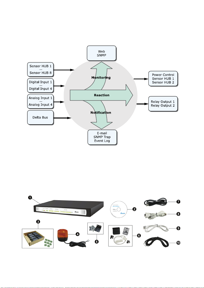
Signal Flow
The following figure explains how EnviroStation monitors and processes signals.
2.3. Package Contents
Please carefully verify EnviroStation and the included accessories. Contact your
dealer if any item is missing or damaged. Should you return the items for any reason,
ensure that they are carefully repacked using the original packing materials that
came with the unit.
InfraSuite EnviroStation 5
Page 11

Chapter 2 : Introduction
No. Item Quantity
❶
EnviroStation 1 PC
❷
Manual and software CD 1 PC
Sensor HUB adapter 8 PCS
❸
Terminal block (for Sensor HUB adapter) 8 PCS
❹
Alarm Beacon 1 PC
❺
Bracket ear (including cage nuts and screws) 1 SET
❻
Door contact sensor 1 SET
❼
AC power cord 1 PC
❽
RJ45 to DB9 cable 1 PC
❾
Standard CAT5 cable 1 PC
❿
Extension cable (for leakage sensor) 1 PC
You will need the following items:
Peripheral devices such as temperature/ humidity/ water leakage sensors and
EnviroProbes are not included in the package. Also, additional Standard CAT5
cables used to cascade EnviroProbes are not included. You will need to obtain these
items separately.
6
Page 12
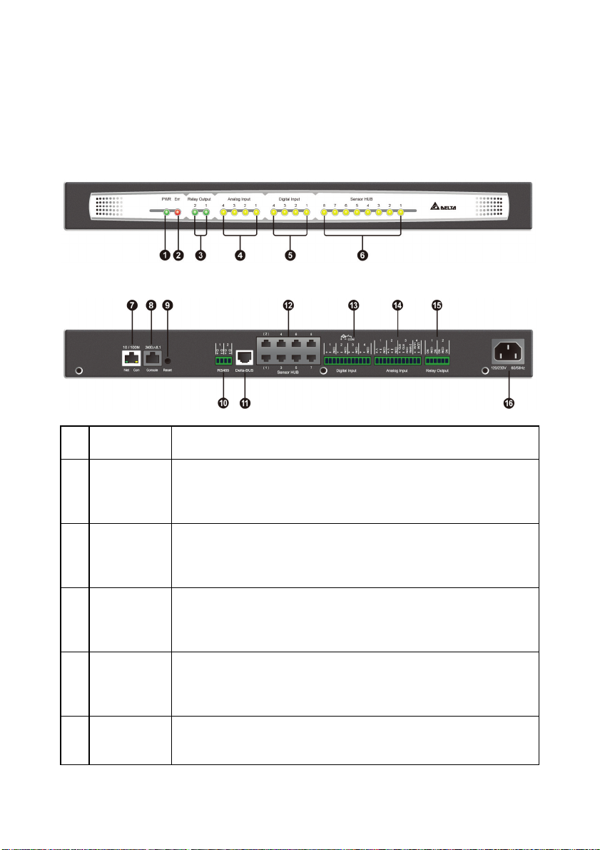
2.4. Interface
The LED indicators and connectors on the front and rear panel are shown as follows.
For their functions and indications, please refer to the table below.
Front panel:
Rear panel:
Item Description
No.
❶
Power
LED
❷
Fault
LED
❸
Relay
Output
LEDs
❹
Analog
Input LEDs
❺
Digital Input
LEDs
InfraSuite EnviroStation 7
Indicates whether the unit is connected to a power source.
On (green): Connected.
Off: Not connected.
Indicates whether an internal fault has occurred.
On (red): Fault occurred.
Off: Normal.
On (green): The Relay Output is switched to NC (Normal
Close).
Off: The Relay Output is switched to NO (Normal Open).
On (yellow): The value of the Analog Input is out of the
assigned normal range.
Off: The value of the Analog Input is in the normal range.
On (yellow): The Digital Input is activated and defined as
‘Warning’ or ‘Alarm’.
Page 13
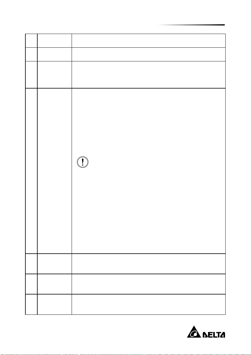
Item Description
W
No.
Off: The Digital Input is defined as ‘None’ or ‘Information’.
❻
Sensor
❼
HUB
LEDs
10/ 100
Base-T
Network
Port
On (yellow): The Sensor HUB is activated and defined as
‘Warning’ or ‘Alarm’.
Off: The Sensor HUB is defined as ‘None’ or ‘Information’.
Connects the EnviroStation to the network.
1. When the EnviroStation initializes or upgrades its firmware,
the two LED indicators on the 10/ 100 Base-T network port
flash simultaneously. Please refer to the following for LED
illumination definition.
Rapid simultaneous flashing (every 50ms):
Initialization or firmware upgrade in progress.
Slow simultaneous flashing (every 500ms):
Initialization failure.
Do NOT disconnect the EnviroStation’s input power
during initialization or firmware upgrade! This could
result in data loss or damage to the EnviroStation.
Chapter 2 : Introduction
arning:
❽
Console
Port
❾
Reset
Button
Modbus
❿
RS485 port
2. The green LED indicator shows the network connection
status:
ON: Network connection established and the IPv4
address is useable.
OFF: Not connected to a network.
Flashes slowly (every 500ms): Faulty IP address.
3. The yellow LED indicator shows the linking status:
Flashes rapidly (every 50ms): Linking normal.
Flashes slowly (every 500ms): Linking abnormal.
Connects to a workstation with an RJ45 to DB9 cable.
Resets the EnviroStation’s network module. This will not affect
the operation of other connected devices.
Connects devices to EnviroStation via the Modbus protocol.
8
Page 14

Item Description
No.
⓫
DeltaBUS
⓬
Sensor
HUB
⓭
Digital Input Four input contact devices can be connected to EnviroStation.
⓮
Analog
Input
⓯
Relay
Output
⓰
AC Line
Inlet
Provides power (12Vdc) and connects to EnviroProbe(s) using
a standard CAT5 cable with straight-through wiring.
Connects and provides power (12/ 24Vdc) to general sensor
devices using standard CAT5 cables with straight-through
wiring.
The wet contact active rating is 5~24Vdc,1~9mA.
Connects four analog sensor devices, including:
Two 0-10Vdc analog voltage sensors or 0-20mA
current-loop sensors.
1 RTD sensor.
1 leakage sensor.
Connects to relay-controlled devices.
Provides power to EnviroStation. The range is 100V~240V 60/
50Hz.
InfraSuite EnviroStation 9
Page 15
Chapter 3 : Installation
In this chapter, you will learn the installation procedures for the EnviroStation,
EnviroProbes, Alarm Beacon, and devices connecting via RS485, Sensor HUB,
Digital Inputs, Analog Inputs and Relay Outputs.
Chapter 3 : Installation
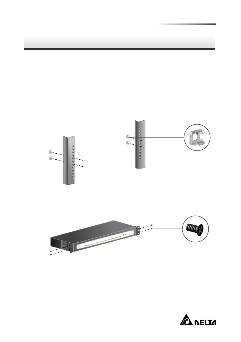
3.1. Rack-mount Installation
Step 1 Choose a location in the rack. On the vertical mounting rails, insert the
provided cage nuts.
Step 2 Using two screws, attach two bracket ears provided in the accessory box
to each end of the EnviroStation.
Step 3 Make sure the mounting holes and the bracket ears on the EnviroStation
are aligned properly, then secure the bracket ears to the rack with the four
provided mounting screws (two for each end), EnviroStation occupies 1U
of rack space.
10
Page 16
W
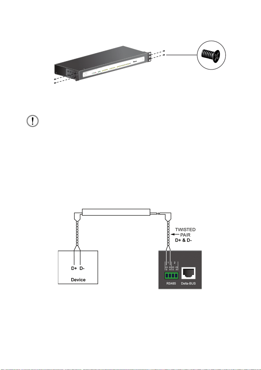
Step 4 Connect the AC power cable from the rear panel to an unoccupied power
outlet. This will automatically power up the EnviroStation.
ARNING:
Before connecting the EnviroStation to a power source, make sure that the
power source is rated between 100-240V and is well grounded.
3.2. RS485
EnviroStation provides two RS485 ports for devices that communicate through the
Modbus protocol such as power meters and door contact systems. Using an RS485
port, eight devices with different ID numbers can be cascaded, however, their
communication parameters must be identical (For example: Baud rate: 2400, data
bits: 8, parity: none, stop bits: 1, and flow control: None).
InfraSuite EnviroStation 11
Page 17
Chapter 3 : Installation
3.3. EnviroProbe
Detecting environment temperature and humidity, the EnviroProbes are designed to
work with the EnviroStation. You can cascade multiple EnviroProbes to extend the
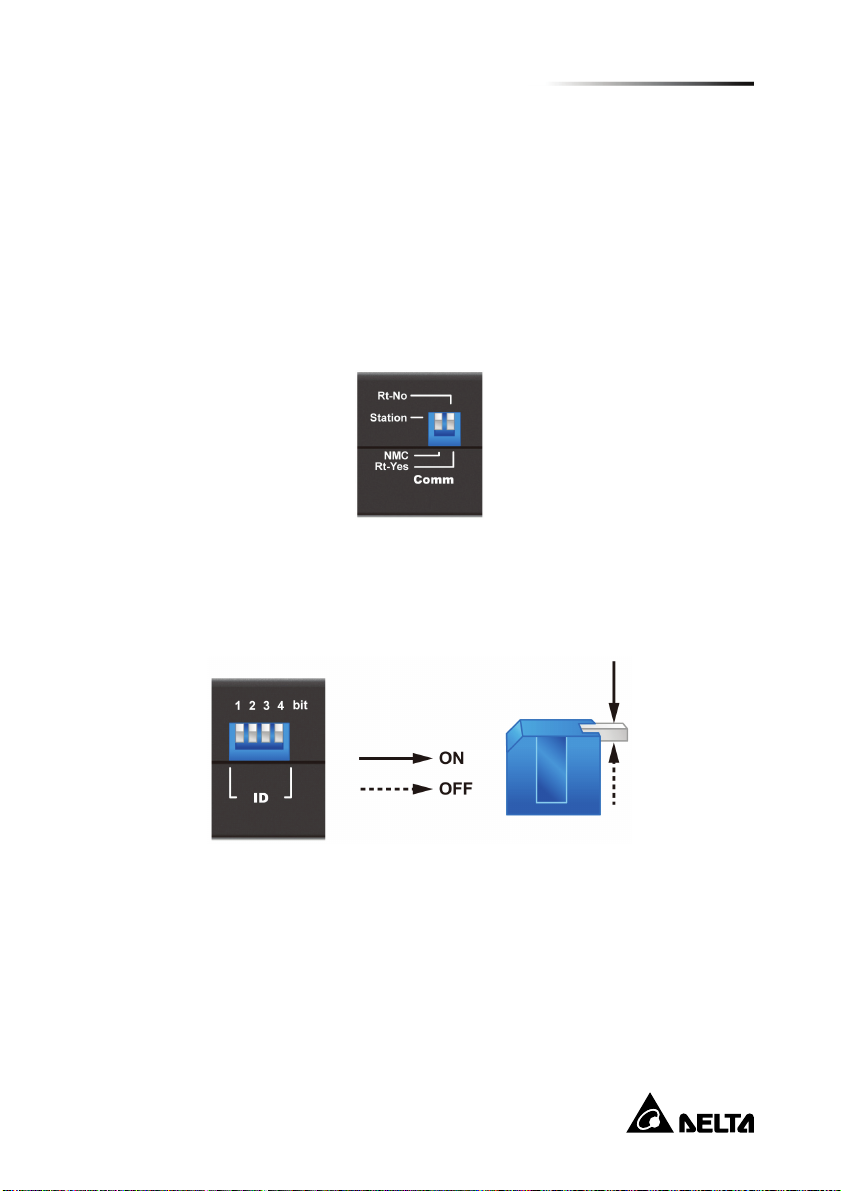
detecting range. To install the EnviroProbe(s), please see the following instructions.
Step 1 Set the Comm DIP switch to Station on the EnviroProbe(s).
Step 2 Make sure the last EnviroProbe in the chain (the farthest) is set to Rt-Yes,
and the rest of the EnviroProbes are set to Rt-No. If only one EnviroProbe
is connected, please also make sure that it is set to Rt-Yes.
Step 3 Set the ID DIP switch to assign an ID for each EnviroProbe (please refer to
the EnviroProbe User Manual). No particular numeric order is required for
the connected units; however, make sure that each EnviroProbe is
assigned with a unique ID. Up to ten EnviroProbes can be cascaded.
Step 4 Attach the EnviroProbe(s) to rack cabinet doors or metal plates.
Step 5 Use a standard CAT5 cable to connect the first (nearest) EnviroProbe’s
Input to the Delta-BUS port on the rear panel.
Step 6 Cascade other EnviroProbes using standard CAT5 cables. Connect the
Output port to the next EnviroProbe’s Input port. Please see the figure
below.
12
Page 18
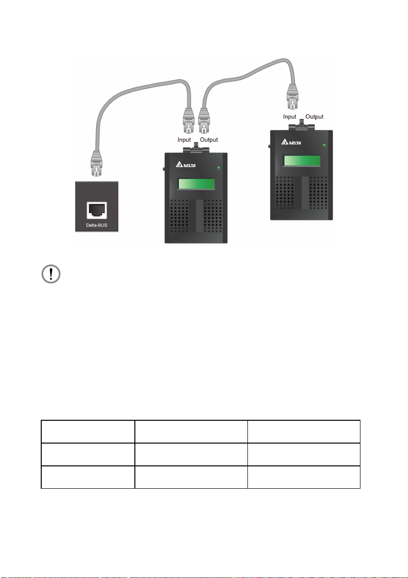
W
ARNING:
Under no circumstance should you connect the EnviroProbe’s Input port to
another one’s Input port. This may cause unrecoverable malfunction to your
EnviroProbes. Please be careful and always make sure that you are
connecting the correct ports before you plug in.
3.4. Digital Input
The EnviroStation provides four Digital Inputs. Wet and Dry Contacts can be
connected for applications such as smoke, fire and door security detection. To
connect your peripheral devices, please refer to the following figures for terminal
connections:
Digital Value Dry Contact Wet Contact
1
0
InfraSuite EnviroStation 13
Close 5~24Vdc
Open < 1.5Vdc
Page 19
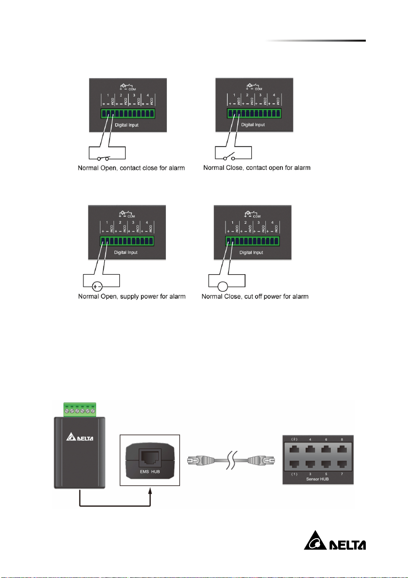
Dry Contact : Normal Open [NO] or Normal Close [NC].
Wet Contact: Active rating 5~24Vdc, 1~9mA.
Chapter 3 : Installation
3.5. Sensor HUB
In the accessory box you can find eight provided Sensor HUB adapters (RJ45 to
6-pin terminal connector) which are used to connect peripheral devices for purposes
such as smoke, fire and door contact detection. To connect a Sensor HUB device,
please see the following instructions:
14
Page 20
Connect a Sensor HUB adapter to a Sensor HUB port on the rear panel with a
standard CAT5 cable.
On the other side of the adapter, plug a 6-pin terminal block (provided with the
package) into the green terminal connector so wires from peripheral devices can
be tightened and fixed with the screws.
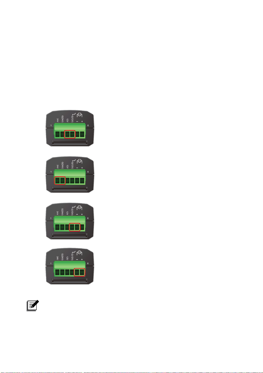
Depending on the contact types and power requirement of the devices you are
connecting, different terminal connections are required. Please see the following
figures:
1) +12Vdc is provided by connecting the
following two terminal points: 12V and G
(12V).
2) +24Vdc is provided by connecting the
following two terminal points: 24V and G
(24V).
3) Connect Dry Contact signal to G (12V) and –
terminal points.
4) Connect Wet Contact signal to + and –
terminal points. The active rating is
5~24Vdc, 1~9mA.
NOTE:
For HUB1/ HUB2, you can manually turn on/ off power or enable automatic
power control. Please see 5.2.1 Management – Sensor HUB.
InfraSuite EnviroStation 15
Page 21
Chapter 3 : Installation
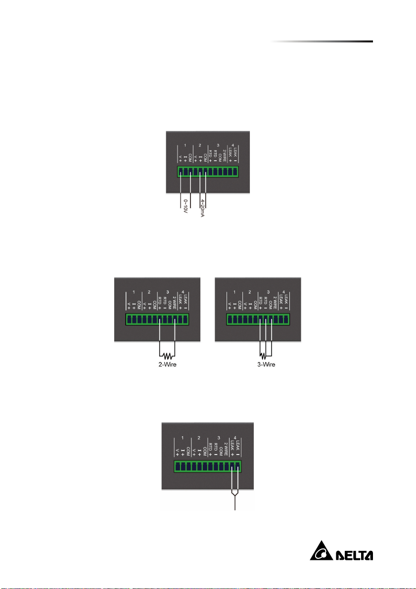
3.6. Analog Input
The EnviroStation provides four Analog Inputs, which are generally used to connect
sensor devices that monitor the environment by observing voltage or current
fluctuations. The Analog Input 1 and 2 can be connected to a voltage (0~10Vdc) or
current (0~20mA) source. Please see the following illustrations.
The Analog Input 3 is dedicated to a 2-wire or 3-wire RTD (Resistance Temperature
Detector) input. You can connect a PT100 (2/3-wire) temperature sensor to it. Please
see the figure below:
The Analog Input 4 is designed to connect a leakage sensor for leakage detection.
You can use the provided extension cable to extend its length.
16
Page 22
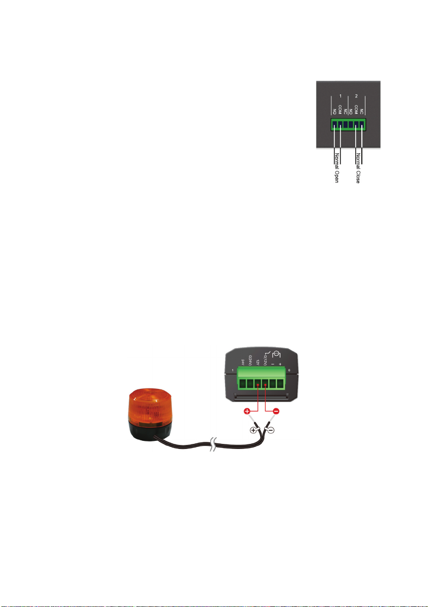
3.7. Relay Output
EnviroStation provides two Relay Outputs which can be
used in cooperation with Digital/ Analog Input devices to take
appropriate actions when events are reported.
The power rating is 26Vdc, 0.8A. Please see the following
illustrations for the terminal configurations:
3.8. Alarm Beacon
The Alarm Beacon can be installed in visible locations and triggered by specific
events to alert you to any unusual situations. To install the Alarm Beacon, a provided
terminal block and a Sensor HUB adapter are needed.
Step 1 Plug the terminal block into the green terminal connector of the Sensor
HUB adapter.
Step 2 Connect the positive wire (+) from the Alarm Beacon to the 12V terminal
on the terminal block, and the negative wire (-) to the G (12V) terminal.
Make sure that the screws on the connected terminals are tightened
properly.
Step 3 Use a standard CAT5 cable to connect the RJ45 connector of the adapter
to the Sensor HUB1/ HUB2 on the rear panel of the EnviroStation.
InfraSuite EnviroStation 17
Page 23
Chapter 3 : Installation
Step 4 Place the Alarm Beacon in a visible location.
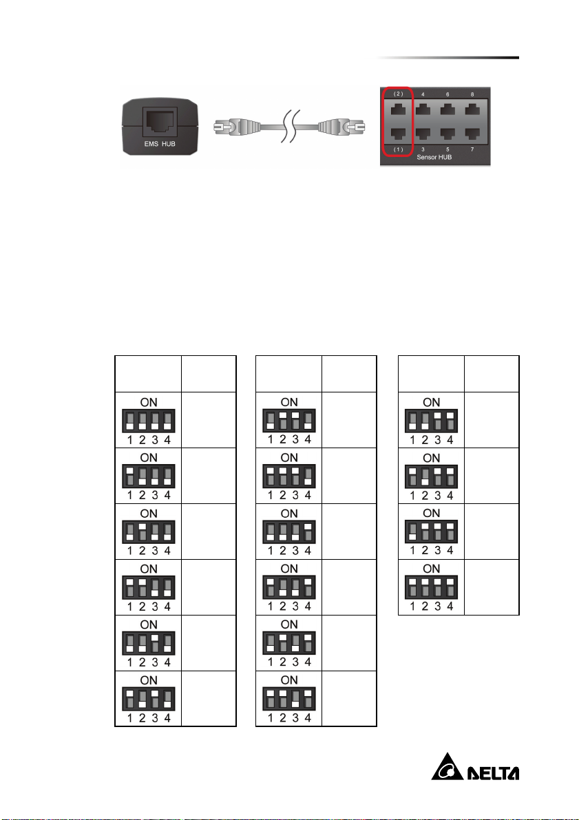
3.9. PDU Installation
Step 1 The EnviroStation can connect with up to 16 PDU devices (different
models are allowed). If you wish to cascade PDU devices, please set a
unique ID No. (0~15) for each PDU with its own four DIP switches (see
Table 3-1).
Table 3-1: Settings of PDU DIP Switches
PDU DIP
Switches
ID
Number
0
1
2
3
4
5
PDU DIP
Switches
ID
Number
6
7
8
9
10
11
PDU DIP
Switches
ID
Number
12
13
14
15
18
Page 24
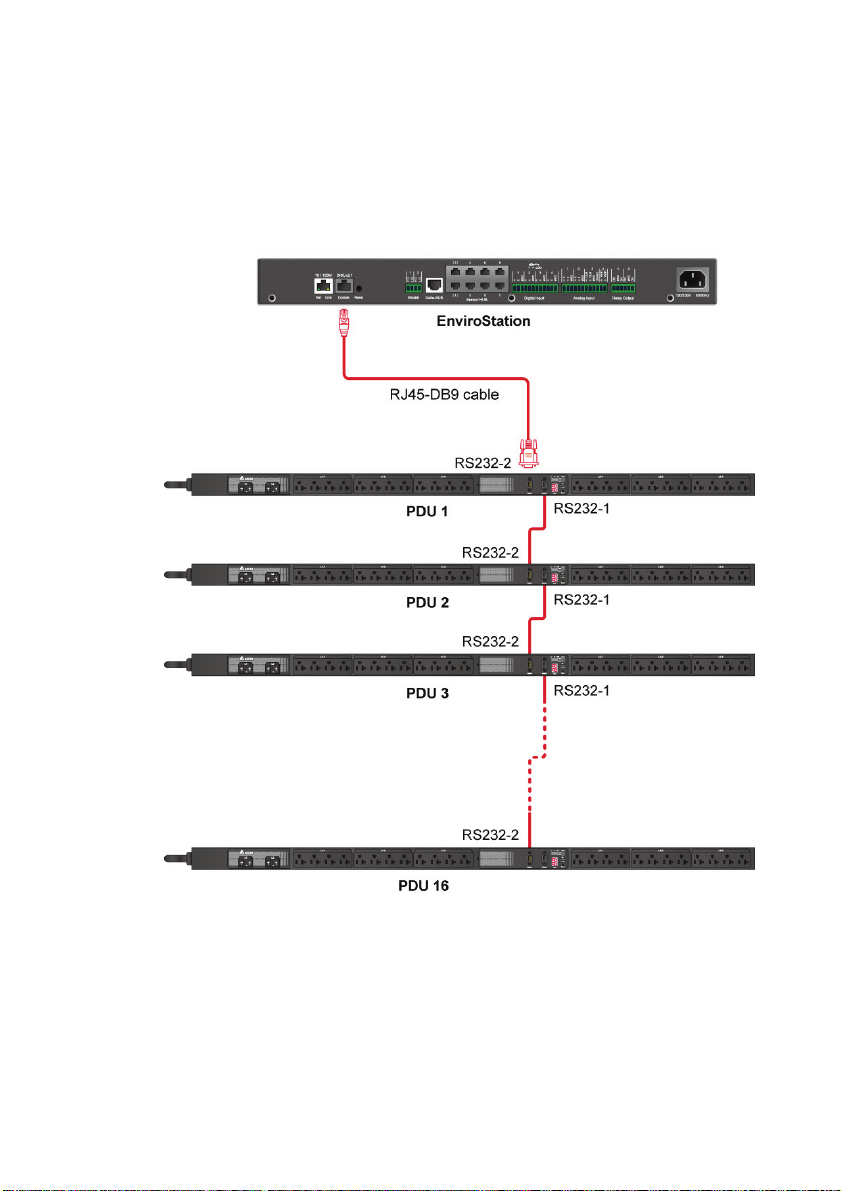
Step 2 Use the provided RJ45-DB9 cable to connect the EnviroStation and your
PDU. Connect the RJ45 to the EnviroStation’s console port and connect
the DB9 to the PDU’s RS232-2 port. If you need to cascade several PDU
devices, please use the RS232 cables provided in your PDU devices.
Please refer to the figure below.
Step 3 After installation, please visit InsightPower SNMP IPv6 for EnviroStation
Web, click Device→ Management→ PDU, and check the PDU Enable
box. Please note that the text mode will be disabled if you check the PDU
Enable box.
InfraSuite EnviroStation 19
Page 25

Chapter 4 : System Configurations
There are different ways you can configure your EnviroStation. If a network connection is available at your location, the following methods can be used:
Web-based interface: The InsightPower SNMP IPv6 for EnviroStation Web
offers comprehensive system management and monitoring. Please refer to
Chapter 5: InsightPower SNMP IPv6 for EnviroStation Web.
EzSetting: Use the provided program EzSetting to quickly set up your SNMP
IPv6. Please refer to 4.2 Configuring with EzSetting.
Telnet mode: Configure your SNMP IPv6 in text mode. Please refer to 4.3
Configuring via Telnet.
The above-mentioned methods require network connection. If not available, you can
use direct COM port connection to set up your EnviroStation. Please see 4.4
Configuring through COM Port.
Chapter 4 : System Configurations
NOTE:
1. To ensure system security, it is highly recommended that you change your
account and password after the first login.
2. If you have multiple EnviroStation units installed in your network, we
highly suggest that you change the EnviroStation’s default Host Name to
avoid conflicts. Also, it is recommended that you disable BOOTP/ DHCP
and manually assign a valid static IP address to the EnviroStation.
4.1. Configuring via InsightPower SNMP IPv6 for
EnviroStation Web
To set up the EnviroStation via your web browser, please follow the instructions
below:
Step 1 Use a CAT5 network cable to connect the EnviroStation’s 10/ 100 Base-T
network port to the network. Launch your web browser. In the address bar,
enter the EnviroStation’s default Host Name InsightPower, or default IP
address 192.168.1.100. If you are unable to connect, please see Chapter
7 : Troubleshooting Q6.
20
Page 26

NOTE:
If you have previously changed the EnviroStation’s Host Name or IP
address, connect with the new settings.
Step 2 Log in as Administrator (default account/ password: admin/ password,
case sensitive).
Step 3 Specify your preferred display language (default: English) from the
dropdown menu on the top right of the page. The EnviroStation
remembers your language preference. In the following instructions,
English is chosen as the display language.
Step 4 Click System → Administration → User Manager. Manage your login
accounts and passwords under the “Local Authentication” subhead. The
access permission for the account types are listed as follows:
1) Administrator: Allowed to modify all settings.
2) Device Manager: Allowed to modify device-related settings.
3) Read Only User: Only allowed to view settings without the permission
to make changes. .
You can manually specify whether users are allowed to log in from other
LANs. If you wish to block login attempts from external connections,
selecting Only in this LAN. Otherwise, select Allow Any.
Step 5 Click System → Administration → TCP/ IP to set Host Name, IP
address, Subnet Mask and Gateway IP for the EnviroStation.
Step 6 Click Time Server to manually set time and date for the system, or enable
automatic time synchronization between the EnviroStation and the time
servers.
NOTE:
To completely set up your SNMP IPv6, please refer to Chapter 5:
InsightPower SNMP IPv6 for EnviroStation Web.
InfraSuite EnviroStation 21
Page 27
Chapter 4 : System Configurations
4.2. Configuring with EzSetting
Included in the provided CD, the EzSetting (compatible with Windows 2000/ 2003/
2008/ XP/ Vista/ 7) allows you to easily configure your EnviroStation and upgrade
firmware on your SNMP devices. Follow the instructions below:
Step 1 Use the provided standard CAT5 cable to connect the 10/ 100 Base-T
network port from EnviroStation's rear panel to the network.
Step 2 Make sure the workstation and the EnviroStation are on the same LAN.
Step 3 Insert the provided CD in the CD-ROM drive. From the root directory,
launch EzSetting.
Step 4 Click Discover to search all available SNMP devices on the LAN. A list of
devices will be shown.
NOTE:
1. If you want to search SNMP devices in a different domain,
change the Subnet and IPv4 Mask/ IPv6 Prefix Length and
click Discover.
2. If the EnviroStation cannot be found, check UDP port 3456 on
the workstation you are using. Make sure it is open.
22
Page 28

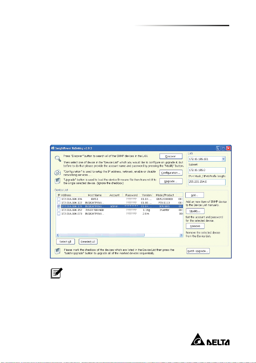
Step 5 Select the SNMP device that you want to modify from the Device List.
Click Modify and enter account and password (default: admin/ password,
case sensitive).
Step 6 Click Configuration to configure network settings.
NOTE:
Refer to Chapter 5: InsightPower SNMP IPv6 for EnviroStation
Web for complete configurations.
InfraSuite EnviroStation 23
Page 29

Chapter 4 : System Configurations
4.3. Configuring via Telnet
Step 1 Use the provided standard CAT5 cable to connect the 10/ 100 Base-T
network port from the rear panel to the network.
Step 2 Connect the workstation (Windows or Linux) to the LAN that the
EnviroStation is connected to.
Step 3 For Windows, launch DOS prompt mode (Start → Run → key in cmd
and press enter). For Linux, launch shell.
Step 4 Enter the following command: telnet InsightPower or telnet IP address
to initiate telnet connection with the EnviroStation.
Step 5 When connection is established, enter account and password (default:
admin/ password, case sensitive). The Main Menu will appear on the
screen. Please refer to 4.5 Configuring via Text Mode for more
information.
NOTE:
1. The EnviroStation will terminate idle connections after 60
seconds.
2. Refer to Chapter 5: InsightPower SNMP IPv6 for
EnviroStation Web for complete configurations.
4.4. Configuring through COM Port
If a network connection is not available at your location, you can still set up the
EnviroStation via COM port connection. Please follow the instructions below.
NOTE:
If you are running a non-Windows system, refer to your system’s User
Manual for Telnet client.
Step 1 Use the provided standard CAT5 cable to connect the 10/ 100 Base-T
network port from the rear panel to the network.
Step 2 For Windows 2000, 2003, 2008 and XP, go to Start → Programs →
Accessories → Communications and select HyperTerminal.
24
Page 30

NOTE:
Microsoft has removed HyperTerminal from Windows Vista and
later versions. If your operation system does not include the
program, a free alternative Telnet/ SSH client PuTTy can be
downloaded from http://www.putty.org.
Step 3 Enter a name, choose an icon for the connection and click OK. From the
dropdown menu connect using, select the COM port that is connected to
the EnviroStation.
Step 4 Click configure and set up COM port parameters as follows:
InfraSuite EnviroStation 25
Page 31

Chapter 4 : System Configurations
Step 5 Click OK to continue. HyperTerminal will automatically connect to the
EnviroStation. If it does not connect, click the telephone icon from the tool
bar. When connection is established, log in with account/ password.
(Default: admin/ password, case sensitive). Once you are logged in, the
Main Menu appears on the screen. Please refer to 4.5 Configuring via
Text Mode for more information.
4.5. Configuring via Text Mode
You can configure the EnviroStation via text mode by using Telnet/ SSH clients such
as HyperTerminal and PuTTy. In this section, you can find descriptions and default
settings.
Main Menu
26
Page 32

User Manager
No Item Description Default
[1] RADIUS Auth Specify whether RADIUS login is
allowed.
[2] Server The RADIUS server name.
[3] Secret The RADIUS secret.
[4] Port The RADIUS port number. 1812
[5] Administrator Account admin
[6] Administrator
Password
[7] Administrator
Limitation
InfraSuite EnviroStation 27
The default account/ password
for the Administrator (case
sensitive).
Restrict Administrator login area. Only in This
Disable
password
LAN
Page 33

Chapter 4 : System Configurations
No Item Description Default
[8] Device Manager
Account
[9] Device Manager
Password
[a] Device Limitation Restrict login area of the Device
Read Only
[b]
User Account
Read Only
[c]
User Password
Read Only
[d]
User Limitation
The default account/ password
(case sensitive) for the Device
Manager who is only permitted to
change device-related settings.
Manager.
The default account/ password
(case sensitive) for Read Only
User who can only observe
settings.
Restrict login area of the Read
Only User.
TCP/ IP Configuration
device
password
Only in This
LAN
user
password
Allow Any
28
Page 34

No. Item Description Default
[1] IPv4 Address The IPv4 address. 192.168.001.100
[2] IPv4 Subnet
Mask
[3] IPv4 Gateway IP The IPv4 network gateway. 192.168.001.254
[4] IPv4 DNS or
WINS IP
[5] DHCPv4 Client Enable/ disable DHCPv4
[6] IPv6 Address The IPv6 address.
[7] IPv6 Prefix Length The IPv6 prefix length.
[8] IPv6 Gateway IP The IPv6 network default
[9] IPv6 DNS IP IPv6 Domain Name Server IP
[a] DHCPv6 Enable/ disable DHCPv6
[b] Host Name
(NetBIOS)
[c] System Contactor The System Contact information.
[d] System Location The System Location
[e] Auto-Negotiation Enable/ disable automatic
[f] Speed If the Auto-Negotiation is
[g] Duplex If the Auto-Negotiation is
[h] Status Stable Status change confirmation
[i] Telnet Idle Time Telnet connection time-out
The IPv4 subnet mask setting. 255.255.255.000
IPv4 Domain Name Server or
WINS IP.
protocol.
gateway.
address.
protocol.
The Host Name for the
EnviroStation.
information.
transfer rate (10/ 100M bps)
negotiation.
disabled, you can specify the
transfer rate.
disabled, you can specify the
duplex mode.
check time.
setting.
192.168.001.001
Enable
Enable
INSIGHTPOWER
Enable
100M
Full
3
60 Seconds
InfraSuite EnviroStation 29
Page 35

Chapter 4 : System Configurations
Network Parameter
No. Item Description Default
[1] HTTP Server Enable/ disable HTTP protocol. Enable
[2] HTTPS Server Enable/ disable HTTPS protocol. Enable
[3] Telnet Server Enable/ disable Telnet protocol. Enable
[4] SSH/ SFTP
Server
[5] FTP Server Enable/ disable FTP protocol. Disable
[6] Syslog Enable/ disable remote syslog. Disable
[7] HTTP Server Port HTTP networking port. 80
[8] HTTPS Server
Port
Enable/ disable SSH/ SFTP protocol. Enable
HTTPS networking port. 443
30
Page 36

No. Item Description Default
[9] Telnet Server Port Telnet networking port. 23
[a] SSH Server Port SSH networking port. 22
[b] FTP Server Port FTP networking port. 21
[c] Syslog Server 1 The remote syslog Host Name.
[d] Syslog Server 2 The remote syslog Host Name.
[e] Syslog Server 3 The remote syslog Host Name.
[f] Syslog Server 4 The remote syslog Host Name.
[g] SNMP Get, Set
Port
The SNMP networking port. 161
Time Server
You can manually adjust time and date for the EnviroStation or set up automatic
time server synchronization. The EnviroStation, Windows XP and later versions
support SNTP (Simple Network Time Protocol). If you need to start up a time
server service on your workstation, please refer to Chapter 7: Trouble-shooting
Q1.
InfraSuite EnviroStation 31
Page 37

Chapter 4 : System Configurations
No. Item Description Default
[1] Time Selection SNTP or manual. SNTP
[2] Time Zone Select the time zone. +0 hr
[3] 1st Time Server The first time server for SNTP. POOL.NTP.ORG
[4] 2nd Time Server The second time server for
SNTP.
[5] Manual Date Set the date manually. (If the
Time Selection is set to Manual)
[6] Manual Time Set the date manually. (If the
Time Selection is set to Manual)
01/01/2000
00:00:00
Soft Restart
Reset the EnviroStation. This will not affect the operation of its connected
devices.
Reset All To Default
Reset to manufacture default.
Exit Without Save
Exit and ignore changes.
Save And Exit
Preserve your changes and exit.
32
Page 38

Chapter 5 : InsightPower SNMP IPv6 for EnviroStation Web
To configure EnviroStation via the InsightPower SNMP IPv6 for EnviroStation Web,
please follow the steps below:
Step 1 Make sure that your EnviroStation is connected to the LAN. Use a
standard CAT5 cable to connect the EnviroStation’s 10/ 100 Base-T
Network Port on the rear panel to your network.
Step 2 Launch your web browser. Enter EnviroStation’s Host Name
http://InsightPower or IP address http://192.168.1.100/ in the address
bar. For encrypted connection, enter https://InsightPower or https:
//192.168.1.100.
Step 3 When connection is established, the EnviroStation Login page appears.
Enter your account and password (Default: admin/ password).
NOTE:
1. If you have previously changed EnviroStation’s Host Name or IP address,
make sure to provide the correct information accordingly.
2. If the login page is accessible, but you are unable to log in with correct
account and password, additional network configuration is needed. The
cause could be the IP subnet of the computer you are logging in to is
different from the EnviroStation’s. To solve this issue, please refer to
Chapter 7: Troubleshooting Q3.
3. EnviroStation will automatically log off idle connections after 30 minutes.
InfraSuite EnviroStation 33
Page 39

Chapter 5 : InsightPower SNMP IPv6 for EnviroStation Web
5.1 Monitor
5.1.1. Information
This includes the information of System Status, Sensor HUB, Digital Input, Analog
Input, Relay Output, Delta Bus, RS485, PDU and IPMI status.
Status
This page presents a status overview of connected devices. The values will be
updated automatically. To set the refresh period, go to System →
Administration → Web → Web Refresh Period.
34
Page 40

Delta Bus
Go to Device → Information → Delta Bus to view the status of cascaded
EnviroProbes. To add or remove Delta Bus devices, click Configuration on the
bottom right corner, or go to Management → Delta Bus.
RS485
To check RS485 device parameters, go to Information → RS485. To add or
remove RS485 devices, click Configuration on the bottom right corner, or go to
Device → Management → RS485.
InfraSuite EnviroStation 35
Page 41

Chapter 5 : InsightPower SNMP IPv6 for EnviroStation Web
PDU
Go to Information → PDU to look up a specific PDU’s ID No., model No., serial
No., hardware version, firmware version, and relevant readings, such as load,
frequency, watt & kWh, etc. You can also click the Data Log and Energy Log
buttons (if your web page shows the two buttons) to view more relevant readings.
For more information about the data log and energy log, please refer to 5.1.2
History - Event Log and 5.1.2 History - Energy Log. If you want to enable a
PDU unit, please click Configuration at the right-down corner or go to Device →
Management → PDU.
IPMI
Go to Information → IPMI to look up a server’s IPMI information, such as
server name, IP address, firmware version, the server’s power status and sensor
status. To add, remove or configure an IPMI device, click Configuration at the
right bottom corner, or go to Device → Management → IPMI Device.
36
Page 42

5.1.2. History
Event Log
This table lists all occurred event. The existing ones are overwritten when the
maximum number of entries (1,000) is reached. You can also download the
entire event log archive (event_log.xls) recorded during an assigned period of
time on your computer.
Date: The date when the event occurred.
Time: The time when the event occurred.
Level: The Event Level of the event that occurred.
Event Log: The description of the event that occurred.
InfraSuite EnviroStation 37
Page 43

Chapter 5 : InsightPower SNMP IPv6 for EnviroStation Web
Energy Log
Go to Monitor → History → Energy Log to look up selected PDUs’ energy
logs. You can set up a specific time, click the Display Detail Data button to view
detailed records and click the Download button to download the energy logs.
The existing records are overwritten when the maximum number of entries
(8,000) is reached.
38
Page 44

Energy Compare
Go to Monitor → History → Energy Compare to see any selected two PDUs’
energy compare table. Choose any two PDUs’ ID No., select a specific time, click
the Apply button, and an energy compare table appears. You can click the
Display Detail Data button to view detailed comparison records and click the
Download button to download comparison logs. The existing records are
overwritten when the maximum number of entries (8,000) is reached.
Data Log
Go to Monitor → History → Data Log to see the analog inputs’ data logs,
EnviroProbe sensors’ data logs and a specific PDU’s data log recorded in a
specific time. The data log includes information about the selected PDU’s total
output frequency, total output power, each branch’s output voltage, output
current and output power. Choose a PDU’s ID No., select a specific time, and its
data log appears. You can click the Download button to download the data log.
The existing records are overwritten when the maximum number of entries
(8,000) is reached.
InfraSuite EnviroStation 39
Page 45

Chapter 5 : InsightPower SNMP IPv6 for EnviroStation Web
Configuration
Go to Monitor → History → Configuration to clear the event log, energy log,
energy compare log, and data log. You can also assign Save Data Interval and
Save Energy Interval.
Clear History Data: Empty the data log only.
Clear Event Log: Empty the event log only.
Clear Energy Data: Empty the energy log and energy compare log.
Save Data Interval: The time interval after which a data entry is recorded.
Save Energy Interval: The time interval after which an energy/ energy
compare entry is recorded.
40
Page 46

5.1.3. About
Information
Go to Monitor → About → Information to see the version of your
InsightPower SNMP IPv6 for EnviroStation and other information about
OpenSSL toolkit and license.
InfraSuite EnviroStation 41
Page 47

Chapter 5 : InsightPower SNMP IPv6 for EnviroStation Web
5.2 Device
5.2.1. Management
The InsightPower SNMP IPv6 for EnviroStation Web allows detailed configurations
for Sensor HUB, Digital Input, Analog Input, Relay Output, Delta Bus, RS485,
Protocol, PDU, IPMI Device, IPMI Template and Reaction.
Sensor HUB
NO/ NC: Stands for Normal Open and Normal Close. If Normal Open is
selected, an event is triggered when 1. Dry Contact is closed or 2. Wet
Contact is provided with 5~24Vdc. If Normal Close is selected, an event is
triggered when 1. Dry Contact is open, or 2. Wet Contact is provided with
<1.5Vdc. Please see the following table:
Digital Value Dry Contact Wet Contact
1 Close 5~24Vdc
0 Open < 1.5Vdc
42
Page 48

Event Type: Allows you to individually determine sensor alarm levels.
Reactions will only be triggered when Warning or Alarm is selected.
Title: You can entitle devices for identification.
Power Configuration: If Normal Open is selected, the EnviroStation
supplies 12Vdc or 24Vdc power to Sensor HUB. If Manual is selected and
Off button is clicked, the power is cut off. You can also set up Reaction
(please see 5-2-1 Management- Reaction) to automatically cut off the
power. Power is cut off during the period of time specified in the Active
Period box. Power resumes after the given duration. If the specified Active
Period is 0, power does not resume.
Digital Input
NO/ NC: If Normal Open is selected, an event is triggered when 1. Dry
Contact is closed, or 2. Wet Contact is provided with 5~24Vdc. If Normal
Close is selected, an event is triggered when 1. Dry Contact is open, or 2.
Wet Con-tact is provided with < 1.5Vdc.
Digital Value Dry Contact Wet Contact
1 Close 5~24Vdc
0 Open < 1.5Vdc
Event Type: Allows you to individually determine the Alarm levels for
sensors. Selecting Alarm or Warning triggers reactions.
Title: You can entitle devices for identification.
InfraSuite EnviroStation 43
Page 49

Chapter 5 : InsightPower SNMP IPv6 for EnviroStation Web
Analog Input
Formula: AI (Analog Input) 1 and AI2 are designed for general Analog
In-puts, each can be connected to a voltage (0~10Vdc) or current (0~20mA)
source. EnviroStation translates the ADC (Analog-to-digital converter) values
according to the following formula: (ADC-a)*b/c-d. You can select the unit
scale and define the unit string for the translated values.
Title: You can entitle devices for identification.
Warning / Alarm: You can set event type to Warning or Alarm.
RTD: The AI3 is designed to connect an RTD device. You can define the
conditions when reactions are triggered for Warning and Alarm levels.
Leakage: The AI4 is designed to connect a leakage sensor. You can select
the sensor sensitivity and Event Type.
44
Page 50

Relay Output
Operation: Select Automatic to enable automatic linking between a specific
relay output and Reaction (please see 5.2.1 Management - Reaction).
Select Manual to set the specific relay output status by clicking the Normal
and Alarm buttons.
Period: The relay output changes its status during the period of time
specified in the Period box. The original relay output status resumes after
the given duration. If the specified Period is 0, the original relay output status
does not resume automatically unless you manually click the Normal button
or set up Reaction (please see 5.2.1 Management - Reaction).
Title: You can entitle devices for identification.
Delta Bus
The EnviroStation communicates with EnviroProbes through the Delta Bus.
There are three types of EnviroProbes, (1) EnviroProbe (EMS1000), (2)
EnviroProbe 1100 (EMS1100) and (3) EnviroProbe 1200 (EMS1200). The Delta
Bus page varies according to different types of EnviroProbes. Please see below:
For EnviroProbe (EMS1000):
The EnviroProbe (EMS1000) provides one temperature/ humidity sensor and
four digital outputs. In this page, select an ID first and then set up Title and
Typ e. Click Enable if you wish to enable the device. Please note that the ID
means the ID No. you set up for your EnviroProbe (EMS1000) using its ID
DIP switches (please see 3.3 EnviroProbe). You can set up Warning and
Alarm conditions for the temperature/ humidity sensor, and define each input
contact’s NO/ NC, Title and Event Type.
InfraSuite EnviroStation 45
Page 51

Chapter 5 : InsightPower SNMP IPv6 for EnviroStation Web
For EnviroProbe 1100 (EMS1100)
The EnviroProbe 1100 (EMS1100) provides four digital outputs. In this page,
select an ID first and then set up Title and Type. Click Enable if you wish to
enable the device. Please note that the ID means the ID No. you set up for
your EnviroProbe 1100 (EMS1100) using its ID DIP switches (please see 3.3
EnviroProbe). You can set up each digital output’s Operation, Period and
Title. Select Automatic to enable automatic linking between a specific digital
output and Reaction (please see 5.2.1 Management - Reaction). Select
Manual to set the specific digital output status by clicking the Normal and
Alarm buttons.
The digital output changes its status during the period of time specified in the
Period box. The original digital status resumes after the given duration. If the
specified Period is 0, the original digital status does not resume automatically
unless you manually click the Normal button or set up Reaction (please see
5.2.1 Management - Reaction).
46
Page 52

For EnviroProbe 1200 (EMS1200)
The EnviroProbe 1200 (EMS1200) provides two analog inputs, one analog
output and one water-leakage detection. In this page, select an ID first and
then set up Title and Ty pe. Click Enable if you wish to enable the device.
Please note that the ID means the ID No. you set up for your EnviroProbe
1200 (EMS1200) using its ID DIP switches (please see 3.3 EnviroProbe).
You can set up the following:
1) Analog Input
Set up each analog input’s ((ADC-a)*b/c-d), Title and Event Settings.
Click the color bar in Event Settings to change event types for different
thresholds of analog inputs. Green, yellow, and red mean normal,
warning, and alarm events respectively.
2) Leakage
Set up leakage’s Sensitivity, Title and Event Type. If you check the
Buzzer Enable box, the EnviroProbe 1200 (EMS1200) will enable
buzzer when it detects water leakage.
3) Analog Output
Set up analog output (Automatic or Manual), Title and Control. If
Manual is selected, Reaction (please see 5.2.1 Management -
Reaction) won’t be able to control analog output.
InfraSuite EnviroStation 47
Page 53

RS485
Chapter 5 : InsightPower SNMP IPv6 for EnviroStation Web
There are two RS485 ports on the rear panel, each port can be configured with a
different baud rate, data bits, parity and stop bit. EnviroStation communicates
with up to 16 Modbus devices in an RS485 port. You can individually select
protocol for each Modbus device from the dropdown menu.
If a suitable protocol cannot be found, you can manually define a special
Mod-bus protocol. Please see 5.2.1 Management - Protocol.
48
Page 54

Protocol
In this page, you can add, modify or delete protocols. You can also export or
import protocols from files for backup purposes. Each protocol contains 32
values and 32 statuses.
InfraSuite EnviroStation 49
Page 55

Chapter 5 : InsightPower SNMP IPv6 for EnviroStation Web
PDU
After you check the PDU Enable box to enable monitoring PDU feature, please
use the provided RJ45-DB9 cable to connect the EnviroStation and your PDU.
Connect the RJ45 to the EnviroStation’s console port and connect the DB9 to the
PDU’s RS232-2 port. For installation information, please refer to 3.9 PDU
Installation. Please note that, once you check the PDU Enable box, the text
mode will be disabled. After you select PDU ID No. and click Submit, the
EnviroStation will monitor the PDU units accordingly.
IPMI Device
IPMI Scan Setting
You can set up IPMI Scan Interval here. After setup, all IPMI devices will be
scanned when the scan time is due.
IPMI Device List
You can enter the Device Name, Username, Password, IP Address, IPMI
Version, Cipher Suite and IPMI Template in this page. Click Add, Update or
Delete to add, modify or delete an IPMI device’s configuration. You can also
add an IPMI device if you enter Username, Password, IP Address, IPMI
Version, Cipher Suite and click the Scan button.
50
Page 56

Device scan result will appear after the scan process is done. You can add a
device that you would like to monitor if you check the Add box, give a device
name, specify its template, and then click the Add button.
InfraSuite EnviroStation 51
Page 57

Chapter 5 : InsightPower SNMP IPv6 for EnviroStation Web
IPMI Template
You can add and delete an IPMI template in this page. You can also modify the
IPMI template to decide how many sensors that you want to monitor.
Template Scan
To scan an IPMI template, you have to enter the Username, Password,
server’s IP Address, IPMI version and Cipher Suite. After clicking the Scan
button, the system will start the template scan.
After scanning, all sensors will be shown in this page. You can specify the
template name and click the New button to create a new IPMI template.
52
Page 58

Temp late
A new template will be shown on the template list after you click the New
button. All sensors belonged to the new template are disabled (default). You
can enable a specific sensor by checking its Enable box. You can also enable
several sensors that you like and group them into a new template by giving a
new template name in the Template Name column. After clicking the Add
button, the new template name will be added into the template list. You can
also Modify or Delete a template name. To export a template file, please click
the Export button and save the file as a new file. To import a template file,
click the Browse button, find the specific template file, and then click the
Import button to import the IPMI template file.
InfraSuite EnviroStation 53
Page 59

Chapter 5 : InsightPower SNMP IPv6 for EnviroStation Web
Reaction
User can add (click +), modify and delete (click -) reaction items in this page.
Click Edit to setup Reaction Rule. EnviroStation supports up to 64 reaction
items.
Reaction Rule includes settings of Weekday, Time, Condition and Output.
When each situation/ condition is met, corresponding outputs will be enabled.
1. Weekday & Time: Set up time.
2. Period: After setting up the Period, the EnviroStation will regularly execute
the Reaction Rule. If the Reaction Rule’s all conditions are met, there will
be corresponding outputs. If the Period is 0 and the Reaction Rule’s all
conditions are met for the 1st time, corresponding outputs will occur.
However, after the 2
outputs.
3. Condition: Set up Device, ID, Type, Port, Operation and Valu e. Click + or to add or delete a condition. You can set up at maximum 16 conditions.
nd
time (included), there will be no corresponding
4. Output: Set up Device, ID, Port and Value. Click + or - to add or delete an
output. You can set up at maximum 16 outputs.
54
Page 60

5.3 System
5.3.1. Administration
User Manager
The EnviroStation supports RADIUS. Check the Use RADIUS box, key in
required information including Server, Secret and Port (default: 1812) and click
submit to enable RADIUS. You can define service types for Administrator,
De-vice Manager and Read Only User. If RADIUS is disabled, you can still
manage the Account Name, Password and Login Limitation for Local
Authentication.
InfraSuite EnviroStation 55
Page 61

Chapter 5 : InsightPower SNMP IPv6 for EnviroStation Web
TCP/ IP
Set IPv4 and IPv6 addresses and fill in system information in this page. Please
refer to the descriptions below.
IPv4 (TCP/ IP Settings for IPv4)
1) DHCP Client: Enable/ disable DHCP. If enabled, DHCP server
automatically assigns an IP address to the EnviroStation.
2) IP Address: The IP address in dotted format (e.g. 192.168.1.100).
3) Subnet Mask: The Subnet Mask for your network (e.g. 255.255.255.0).
4) Gateway IP: The IP address for network gateway in dotted format (e.g.
192.168.1.254).
5) DNS IP: The IP address Domain Name Server in dotted format (e.g.
192.168.1.1).
6) Search Domain: If the Host Name you provided cannot be found, the
system appends the search domain to your Host Name.
56
Page 62

IPv6 (TCP/ IP Settings for IPv6)
1) DHCP Client: Enable/ disable DHCP. If enabled, DHCP server
automatically assigns an IP address to the EnviroStation.
2) IP Address: The IPv6 address.
3) Prefix Length: The prefix length for the IPv6 address.
4) Gateway V6IP: The IP address for the IPv6 network gateway.
5) DNS V6IP: The IP address for the IPv6 domain name server.
System
1) Host Name: The SNMP Host Name on the network.
2) System Contactor: System contact information .
3) System Location: System location information.
Link
1) Auto-Negotiation: Enable/ disable automatic transfer rate (10/ 100M
bps) negotiation.
2) Speed: If Auto-Negotiation is disabled, you can specify the transfer rate.
3) Duplex: If Auto-Negotiation is disabled, you can specify the duplex mode.
Web
This allows Administrator to enable/ disable HTTP/ HTTPS communication
protocols.
InfraSuite EnviroStation 57
Page 63

Chapter 5 : InsightPower SNMP IPv6 for EnviroStation Web
Web
1) HTTP: Enable/ disable HTTP connection.
2) HTTPS: Enable/ disable HTTPS connection.
3) HTTP Port: Assign an HTTP port number (default: 80).
4) HTTPS Port: Assign an HTTPS port number (default: 443).
5) Web Refresh Period: Web refresh update interval.
SSL Certificate
1) To ensure connection security between the EnviroStation and the
connecting workstation, SSL certificates can be used to encrypt and
secure the integrity of transmitting data.
2) Certificate File: This allows you to replace your own SSL certificate file.
The EnviroStation supports PEM format which is generated by OpenSSL.
Click Choose File to upload a certificate file.
NOTE:
For more information regarding generating a private SSL certificate file,
please refer to Chapter 7: Troubleshooting Q12, or visit http://
www.openssl.org/.
58
Page 64

Console
This page allows you to enable or disable Telnet/ SSH communication protocols
and replace DSA/ RSA keys.
Telnet: Enable/ disable Telnet connection.
SSH/ SFTP: Enable/ disable SSH/ SFTP connection.
Telnet Port: Assign a Telnet port number (default: 23).
SSH Port: Assign an SSH protocol port number (default: 22).
Host Key:
DSA/ RSA Key: This allows you to replace your own SSH keys. The
EnviroStation supports key files generated by OpenSSH. Please refer to
Chapter 7: Troubleshooting Q13.
InfraSuite EnviroStation 59
Page 65

Chapter 5 : InsightPower SNMP IPv6 for EnviroStation Web
FTP
This allows you to enable/ disable FTP communication Protocol.
FTP: Enable/ disable FTP connection.
FTP Port: Assign an FTP port number (default: 21).
Time Server
You can manually set the time and date, or enable automatic time
synchronization with SNTP servers. Please note that if the SNTP server is not
responsive, the event and data log will not register even when SNTP is enabled.
60
Page 66

Simple Network Time Server
1) Time Zone: From the dropdown menu, select the time zone for the
location where the EnviroStation is located.
2) Primary/ Secondary Time Server: Two time servers can be added.
Every 60 minutes, the EnviroStation synchronizes with the first
responding server.
3) Enable Daylight Saving: Check to enable daylight saving time. During
this period, the EnviroStation adjusts time forward one hour.
Manual
If a time server is not accessible, you can still manually set time and date.
Please note that every time you restart EnviroStation’s network module, time
and date is reinstated to previous assigned settings.
Syslog
Syslog is used to store event log on remote syslog servers. This will not affect
the local event log.
InfraSuite EnviroStation 61
Page 67

Chapter 5 : InsightPower SNMP IPv6 for EnviroStation Web
Batch Configuration
The EnviroStation provides batch configuration to allow quick and effortless
setup on multiple EnviroStations and SNMP devices. You can duplicate settings
by exporting configuration files from the devices that you have successfully
configured, and import the configuration files on other devices.
System Configuration
The System Configuration includes settings saved in the Management and
Administration tabs. To download a configuration file, simply click Download.
To upload a configuration file, click Choose File, select the file you wish to
upload, and click Upload.
NOTE:
If the IP address is static and you wish to copy settings to other devices
on the same LAN, you must manually remove the following line
IP=xxx.xxx.xxx.xxx under the [System] section from the exported
configuration file. You can open the configuration file with text editors
such as Notepad and WordPad. (To modify/ assign IP address for the
EnviroStation, please see Chapter 4: System Configurations).
62
Page 68

SNMP Configuration
The SNMP Configuration includes settings in the Notification tab. To
download a configuration file, simply click Download. To upload a
configuration file, click Choose File, select the file you wish to upload, and
click Upload.
NOTE:
If you need to modify the command lines, please do not delete the
unmodified ones. They should be left intact to assure the integrity of the
configuration file.
Upgrade
Check for latest firmware upgrades at http://59.125.232.140/en/index.aspx. A
firmware upgrade to your EnviroStation can be performed within just a few clicks.
Click Choose File to select a valid firmware package from your directory, then
click Upload. The upgrade process should take about one minute to complete.
InfraSuite EnviroStation 63
Page 69

Chapter 5 : InsightPower SNMP IPv6 for EnviroStation Web
5.3.2. Notification
SNMP Access
The EnviroStation supports SNMP protocol and SNMP NMS (Network
Management System), which are commonly used to monitor network devices for
conditions that call for administrative attention. To prevent unauthorized access,
you can specify the NMS IP addresses that are allowed to access with their
respective Community Strings and access levels. The maximum number of IP
en-tries is 256.
NOTE:
If IP address 0.0.0.0 is enlisted, the NMS IP access restriction is
ignored. EnviroStation checks the Community Strings to identify the
access level and permission according to your setting.
64
Page 70

SNMPv3 USM
SNMPv3 offers features such as the encryption of packets and authentication to
improve security. The SNMPv3 USM (User Session Management) allows you to
assign eight User Names whose access is granted via SNMPv3 protocol. You
can also define their respective Security Levels, Auth Passwords, Priv
Passwords and Access Level.
SNMP Trap
SNMP Trap alerts users to event occurrences in your monitored environment. To
enable SNMP Trap, you must add Target IP addresses to the Target IP list.
Specify the Community String, Trap Type, Event Level, SNMPv3 User Name and
UDP Port, then click Add.
You can determine what event notifications should be sent to the Target IP(s)
from Event Level. Three Event Levels are listed as follows:
InfraSuite EnviroStation 65
Page 71

Chapter 5 : InsightPower SNMP IPv6 for EnviroStation Web
Information: All event notifications are sent to the target address.
Warning: Both Warning and Alarm event notifications are sent to the target
address.
Alarm: Only Alarm event notifications are sent to the target address.
Mail Server
You can set up an SMTP Server and specify a list of E-mail recipients who will
receive notifications when events occur. The maximum number of recipients is
256.
NOTE:
If a DNS server is not available in the network, you need to manually
assign an SMTP server address to enable E-mail notification.
66
Page 72

SMTP Server Name or IP: If a Host Name is entered, a DNS IP should be
added in TCP/ IP. Please see 5.3.1 Administration – TCP/ IP.
Account: The mail server login account.
Password: The mail server login password.
Receiver: The recipients’ E-mail addresses.
Event Level: Select the Event Level that when triggered, an E-mail
notification is sent to the corresponding recipient.
1) Information: All event notifications are sent to the target address.
2) Warning: Warning and Alarm event notifications are sent to the tar-get
address.
3) Alarm: Only Alarm event notifications are sent to the target address.
InfraSuite EnviroStation 67
Page 73

Chapter 6 : SNMP Device Firmware Upgrade
Chapter 6 : SNMP Device Firmware Upgrade
With the provided program EzSetting, you can effortlessly perform a firmware
upgrade for SNMP devices via LAN. Please refer to the following instructions.
Step 1 The subnet mask allows you to refine the device discovery range in the
specified subnets. Make sure the SNMP device you wish to upgrade is in
the subnet that is specified. If it is not, please modify the subnet and
subnet mask.
Step 2 Click Discover. A list of SNMP devices is shown.
68
Page 74

Step 3 Select a device from the Device List, click Modify, and key in
Administrator account and password.
Step 4 Click Upgrade. The upgrade dialog box pops up. Click Browse to select a
valid firmware binary file. Verify the firmware version listed under File
Information, and then click Upgrade Now to continue.
InfraSuite EnviroStation 69
Page 75

Chapter 6 : SNMP Device Firmware Upgrade
Step 5 The upgrade process should take about 20 seconds.
Step 6 When the upgrade is completed, the following dialog box appears. It takes
about 1 minute for the device to reboot.
70
Page 76

Q1. How to set up an SNTP server on my workstation for EnviroStation to
synchronize?
To enable SNTP services in Windows XP, go to Start → Control Panel →
Add/ Remove Programs → Add/ Remove Windows Components →
Networking Services → check Simple TCP/ IP Services → OK. To enable
time synchronization, you need to set SNTP time server addresses in Time
Server. Please refer to Chapter 4: System Configurations.
Q2. How to make sure that network connection is established between my
workstation and EnviroStation?
To check connection between the EnviroStation and workstation, in Windows
please launch DOS prompt mode (Start → Run → key in cmd and press
enter). In Linux, launch Shell. Enter the following command: ping Host
Name (default: InsightPower). If the connection is correctly established, you
should be able to receive replies from the EnviroStation.
Chapter 7 : Troubleshooting
Q3. I can access the login page, but cannot log in to the InsightPower SNMP
IPv6 for EnviroStation Web.
Please check the IP addresses of the EnviroStation and the workstation you
are trying to log in to. The cause could be they are not connected to the same
LAN. In that case, launch EzSetting and change User Limitation settings to
Allow Any. Please see the following figure.
InfraSuite EnviroStation 71
Page 77

Chapter 7 : Troubleshooting
Q4. Unable to connect the EnviroStation via its Host name?
If you assign a new static IP address to the EnviroStation, you may need to
re-fresh the NetBIOS table so that it corresponds with the new one. Although
Windows updates its NetBIOS table periodically, you can still manually force it
to refresh by entering the following command nbtstat –R in DOS prompt mode
or shell. After that, you can now connect to the EnviroStation by its Host Name.
Please also ensure that the Host Name assigned to the EnviroStation does not
exceed 16 bytes.
Q5. How to check my workstation’s IP address?
For Windows, please enter ipconfig /all in DOS prompt mode. For UNIX,
please enter ifconfig in shell. You should be able to check your IP and MAC
(Physical Address) now.
72
Page 78

Q6. Unable to ping the EnviroStation from my workstation?
If the EnviroStation is non-responsive, check the following:
1) If the green LED indicator on the EnviroStation is OFF, check if the
network cable is correctly connected from the EnviroStation to the router
or hub.
2) If the green LED indicator is ON, the current IP address could be
unreachable. Manually assign a valid IP address to the EnviroStation.
3) If the green LED indicator flashes and (1) your network configuration
includes a DHCP server, make sure the DHCP service is working properly;
(2) Otherwise, make sure the assigned IP is not already taken on the
network. Please note that if the current configuration is not useable, the
EnviroStation will reset to default IP settings (IPv4 address:
192.168.1.100/ net mask: 255.255.255.0/ gateway: 192.168.1.254).
4) If the problem persists, use a network cable to cross link your
EnviroStation and the workstation. Ping the EnviroStation’s default or
static IP address, according to your configurations. If a ping response is
successfully received, indicating that the EnviroStation is working properly.
Check your network equipment. If not, contact your local dealer or service
personnel for assistance.
Q7. Unable to perform an SNMP Get command?
Refer to 5.3.2 Notification to check SNMP settings. Make sure that the
workstation’s IP address is added to the NMS IP list with Read or Read/ Write
access. The community string on the workstation and the SNMP IPv6 must
match.
Q8. Unable to perform an SNMP Set command?
Refer to 5.3.2 Notification to check SNMP settings. Make sure that the
workstation’s IP address is added to the NMS IP list with Read or Read/ Write
access. The community string on the workstation and the SNMP IPv6 must
match.
Q9. Unable to receive SNMP trap?
Refer to 5.3.2 Notification to check SNMP Trap settings. Make sure that the
workstation’s IP address is added to the Target IP list.
InfraSuite EnviroStation 73
Page 79

Chapter 7 : Troubleshooting
Q10. Forgot Administrator’s account and password?
You can reset Administrator’s account and password via text mode. Refer to
4.4 Configuring through COM Port to establish a COM port connection with
the EnviroStation. When the login information is prompted, key in rstadmin
within 30 seconds and press enter. The Administrator account and password
are now reset to default (admin/ password).
Q11. How to enable IPv6 in Windows XP?
If you are operating in Windows XP, please enable IPv6 first (click START →
RUN, and enter ipv6 install). The EnviroStation supports IPv6, therefore, no
additional configuration is required. However, please note that IPv6 is
automatically disabled if an identical LLA (Local-link Address) already exists in
the LAN. Also, when the IPv4 and IPv6 settings coexist, IPv4 is used as the
primary IP address for the EnviroStation.
To learn more information regarding IPv6 compatibility, please visit IETF
(http://tools.ietf.org/html), or IPv6 Ready Logo Program
(http://www.ipv6ready.org).
Q12. How to generate a private SSL (Secure Socket Layer) certificate file (in
PEM format) for HTTP connection?
To ensure connection security between the EnviroStation and your browser,
you can create your own SSL certificate file in Linux. Please download and
in-stall OpenSSL from http://www.openssl.org, launch shell and enter the
following command to create your own certificate file:
openssl req –x509 –nodes –days 3650 –newkey rsa:1024 –keyout
cert.pem –out cert.pem
1) Answer the prompted questions. Proceed as directed by the messages.
Once it is completed, a file named cert.pem is created in the current
working directory.
2) Upload cert.pem on the InsightPower SNMP IPv6 for EnviroStation Web.
Please refer to 5.3.1 Administration – Web.
Q13. How to generate DSA and RSA keys for SSH?
For Linux:
1) Please download and install OpenSSH from http://www.openssh.org.
74
Page 80

2) Launch shell and enter the following command to create your own keys:
Please ignore it when prompted to provide passphrase.
DSA Key:ssh-keygen –t dsa
RSA Key:ssh-keygen –t rsa
3) Upload DSA and RSA key files on the InsightPower SNMP IPv6 for
EnviroStation Web. Please refer to 5.3 Administration – Console for more
information.
For Windows:
1) Please download and install PuTTY from http://www.putty.org.
2) Run puttygen.exe from the installed directory.
3) Select SSH-2 RSA from the Parameters area and click Key → Generate
key pair to generate an RSA key.
4) Select Conversions → Export OpenSSH Key and assign a file name to
the RSA key. Please ignore it when prompted to provide key passphrase.
InfraSuite EnviroStation 75
Page 81

Chapter 7 : Troubleshooting
5) Select SSH-2 DSA from the Parameters area and select Key → Generate
key pair to generate a DSA key.
6) Select Export OpenSSH Key from Conversions and assign a file name to
the DSA key. Please ignore it when prompted to provide key passphrase.
7) Copy the generated key from the text box, paste in a text editor and save
as a text file.
8) Upload the DSA/ RSA/ Public key files to the InsightPower SNMP IPv6 for
EnviroStation Web. Please refer to 5.3 Administration – Console for more
information.
Q14. How to upload configuration / firmware / key files via SSH/ SFTP?
To quickly configure your SNMP IPv6, you can upload the files via SSH/ SFTP.
The SNMP IPv6 automatically imports your settings after the files are uploaded
to the designated directories. Refer to the following table:
Directory Files
\config_snmp snmp.ini
\config_system configure.ini
\ssh_dsa DSA Key
\ssh_rsa RSA Key
\ssh_pubkey Public Key
\upgrade_snmp EnviroStation firmware upgrade package (binary)
\upgrade_device* Device’s firmware upgrade package (binary)
* Appears on specific devices only.
Upload files to their respective directories. Make sure the filenames do not
contain non-English characters to avoid read error. Overwrite existing files if
prompted by your SFTP client.
Q15. How to test SNMPv3 in Linux?
Before you can access the SNMP OID (Object Identifier) via SNMPv3 protocol,
the SNMPv3 USM table must be organized. Please refer to 5.3.2
Notification – SNMPv3 USM for more information.
To test SNMPv3 in Linux, launch shell and key in the following command:
76
Page 82

snmpwalk -v 3 -u <user> -l authPriv -A <password> -X <pass-word> -n
<context name> -t 3 <ip> 1.3.6.1.2.1.1.1.0
-v:1 for SNMPv1, 3 for SNMPv3.
-l: Follow the security levels. They are: noAuthNoPriv, authNoPriv and
authPriv.
-u:The user name which is assigned from SNMPv3 USM table.
-A:The Auth Password which is assigned from SNMPv3 USM table.
-X:The Priv Password which is assigned from SNMPv3 USM table.
-n:The Context Name which is assigned from SNMPv3 USM table.
-t: Timeout in seconds.
<ip>: The IP address of the EnviroStation.
<oid>:The next available SNMP OID (For example: 1.3.6.1.2.1.1.1.0). Please
refer to the RFC1213 MIB.
Q16. Why EnviroStation cannot monitor PDU devices?
Monitoring PDU devices is disabled (EnviroStation default). To monitor PDU
devices, please use the InsightPower SNMP IPv6 for EnviroStation Web
(Device → Management → PDU) to reset the default setting. Please refer
to Chapter 5: InsightPower SNMP IPv6 for EnviroStation Web.
InfraSuite EnviroStation 77
Page 83

Appendix A : Specifications
Item
Input
Power Input 100 ~ 240 Vac, 1.2A, 50/60 Hz
Digital Input
Analog Input
RTD
Leakage
Network Connection RJ45 jack connector
Output
Sensor HUB
Delta Bus + 12V, 0.8A (max)
Relay Outputs 26 Vdc (max), 0.8A (max)
Physical
Size (W x D x H) 440 x 157 x 44 mm
Weight 2.4 kg
Environmental
Operating Temperature 0 ~ 45°C
Storage Temperature - 20°C ~ 60°C
Operating Humidity 0 ~ 90% RH (non-condensing)
Appendix A : Specifications
Model Part no.
EMS2000 EMS2000000
Wet Contact signal
Alarm Voltage:5 ~ 24 Vdc
Dry Contact signal
Normal: Off (open circuit)
Alarm: On (short circuit)
Input Voltage: 0 ~ 10V
Input Current: 0 ~ 20 mA
Range: 0 ~ 50°C
Accuracy: ± 1°C with 3-wire PT100
Detect Voltage < 1V
(alarm signal with S-1FP leak sensor)
+ 12V, 0.8A (max)
+ 24V, 1.0A (max)
One port limit 0.6A
NOTE:
1. Refer to the rating label for the safety rating.
2. All specifications are subject to change without prior notice.
78
Page 84

W
f
f
No. 353413901011
Version : V 10.11
UM Date : 2013_02_22
Seller warrants this product, if used in accordance with all applicable instructions, to
be free from original defects in material and workmanship within the warranty period.
If the product has any failure problem within the warranty period, Seller will repair or
replace the product at its sole discretion according to the failure situation.
This warranty does not apply to normal wear or to damage resulting from improper
installation, operation, usage, maintenance or irresistible force (i.e. war, fire, natural
disaster, etc.), and this warranty also expressly excludes all incidental and
consequential damages.
Maintenance service for a fee is provided for any damage out of the warranty period.
If any maintenance is required, please directly contact the supplier or Seller.
Appendix B : Warranty
The individual user should take care to determine prior to use whether the
environment and the load characteristic are suitable, adequate or safe for the
installation and the usage of this product. The User Manual must be carefully
ollowed. Seller makes no representation or warranty as to the suitability or
itness of this product for any specific application.
InfraSuite EnviroStation 79
ARNING:
Page 85

Page 86

Page 87

Page 88

 Loading...