

Page 1
E5
Operation and Installation Manual
Hybrid Inverter
The power behind competitiveness
www.deltaww.com
Page 2

Page 3

09
09
09
09
10
10
10
12
13
14
18
18
20
20
20
21
23
24
25
26
28
28
29
29
30
32
32
33
34
34
35
35
36
36
37
38
39
Table of Contents
1 General Information
1.1 About this Manual
1.2 Product Description
1.3 Additional Information
2 Product Overview
2.1 Unpack the Inverter
2.2 Checking Unit and Accessories
2.3 Product Label
2.4 Exterior Objects
3 Installation
4 Wiring
4.1 Preparation Before Wiring
4.2 AC Connection
4.2.1 Required Protective Devices and Cable Cross-sections
4.2.2 AC Connection
4.2.3 AC Plug Assembly
4.2.4 AC Plug Shield Assembly
4.3 DC Connection (from PV Array)
4.4 Battery Connection
4.5 CAN Connection
4.6 Communication Module Connections
4.7 RS-485 Connection
4.8 Digital Input / DRM & EPO Functions
4.9 Dry Contact Connection
4.10 Multiple inverter combinations
5 Turning On the Hybrid Inverter
5.1 LCD Flow Chart
5.2 First startup
5.3 Home Page
5.3.1 Meter
5.3.2 Energy Log
5.3.3 Event Log
5.3.4 Inverter Information
5.3.5 General Settings
5.3.6 Operation Mode
5.3.6.1 Self-consumption mode
5.3.6.2 Peak cut mode
. . . . . . . . . . . . . . . . . . . . . . . . . . . . . . . . .
. . . . . . . . . . . . . . . . . . . . . . . . . . . . . . . .
. . . . . . . . . . . . . . . . . . . . . . . . . . . . . . .
. . . . . . . . . . . . . . .
. . . . . . . . . . . . . . . . .
. . . . . . . . . . . . . . . . . . . . . . . . . .
. . . . . . . . . . . . . . . . . . . . . . . . . . . . . . . . . . .
. . . . . . . . . . . . . . . . . . . . . . . . . . . . . . . . . .
. . . . . . . . . . . . . . . . . . . . . . . . . . . . .
. . . . . . . . . . . . . . . . . . . . . . . . . . . . . . . . . .
. . . . . . . . . . . . . . .
. . . . . . . . . . . . .
. . . . . . . . . . . . .
. . . . . . . . . . . . . . . . . . . . . . . . . . . . . . . .
. . . . . . . . . . . . . . . . . . . . . . . . . . . . . . . .
. . . . . . . . . . . . . . . . . . . . . . .
. . . . . . . . . . . . . . . . . . . . . . . . . . . . . . . . . .
. . . . . . . . . . . . . . . . . . . . . . . . . . . . .
. . . . . . . . . . . . . . . . . . . . . . . . . . . . . . . . .
. . . . . . .
. . . . . . . . . . . . . . . . . . . . . . . . . . .
. . . . . . . . . . . . . . . . . . . . . . .
. . . . . . . . . . . . . . . . . . . . . . . . . . . . . .
. . . . . . . . . . . . . . . . . . . . . . . . . . .
. . . . . . . . . . . . . . . . . . . . . . . . . . . . . . . . . .
. . . . . . . . . . . . . . . . . . . . . . . . . . . . . . . . . . . .
. . . . . . . . . . . . . . . . . . . . . . . . . .
. . . . . . . . . . . . .
. . . . . . . . . . . . . . . . . . . . . . . . . . . . . . . . . . . .
. . . . . . . . . . . . . . . . . . . . . . . . . . . . . . . . . . . . .
. . . . . . . . . . . . . . . . . . . . . . . . . . . . . . . .
. . . . . . . . . . . . . . . . . . . . . . . . . . . . . . . . .
. . . . . . . . . . . . . . . . . . . . . . . . . . . . . . . . . .
. . . . . . . . . . . . . . . . . .
. . . . . . . . . . . .
. . . . . . . . . . . . . . . . . . . . . . . . . . . . . . . . . .
. . . . . . . . . . . . . . . . . . . . . . . . . . . . . . . . . . . .
. . . . . . . . . . . . . . . . . . . . . . . . . . . . . . . . . .
. . . . . . . . . . . . . . . . . . . . . . . . . . . . . . . . . . . .
. . . . . . . . . . . . . . . . . . . . . . . . . . . . . . . . . . . . . . . .
. . . . . . . . . . .
. . . . . . . . . . . . . . . . . . . . . . . . . . . . . . . .
. . . . . . . . . . . . . . . . . . . . . . . . . . . .
3
Page 4

5.3.6.3 Selling first mode
5.3.6.4 Charge first mode
5.3.6.5 Discharge first mode
5.3.6.6 Without battery mode
5.3.6.7 Special Modes
5.3.7 Function Setting
5.3.8 Install Settings
6 Maintenance
7 Error message and Trouble Shooting
8 De-Commissioning
9 Technical Data
40
41
43
44
45
47
48
50
51
55
56
. . . . . . . . . . . . . . . . . . . . . . . . . . . . . . . . . .
. . . . . . . . . . . . . . . . . . . . . . . . . . . . . . . . . .
. . . . . . . . . . . . . . . . . . . . . . . . . . . . . . . . . .
. . . . . . . . . . . . . . . . . . . . . . . . . . . . . . .
. . . . . . . . . . . . . . . . . . . . . . . . . . . . . . .
. . . . . . . . . . . . .
. . . . . . . . . . . . . . . . . . . .
. . . . . . . . . . . . . . . . . . . . . . . . . . . . . . . . .
. . . . . . . . . . . . . . . . . . . . . . . . . . . . . . . . . . . . . . .
. . . . . . . . . . . . . . . . . . . . . . . .
. . . . . . . . . . . . . . . . . . . . . . . . . . . . . . . . . . .
. . . . . . . . . . . . . . . . . . . . . . . . . . . . . . . . . . . . .
4
Page 5

Figure 1-1 : Storage system operation illustration
Figure 2-1 : Unpack the inverter
Figure 2-2 : Packing list
Figure 2-3 : Product label
Figure 2-4 : Inverter’s exterior objects
Figure 2-5 : Input / output interface
Figure 3-1 : Mounting bracket dimension
Figure 3-2 : Recommended installation
Figure 3-3 : Screw the mounting bracket
Figure 3-4 : Attach to the bracket and fasten with screws
Figure 3-5 : Proper installation gaps
Figure 4-1 : Connection of system for floating solar array and battery
Figure 4-2 : AC connection
Figure 4-3 : Terminal for wire crimping
Figure 4-4 : Striping the wires
Figure 4-5 : AC plug illustration for E5
Figure 4-6 : AC Plug Shield Assembly
Figure 4-7 : DC plug wiring illustration
Figure 4-8 : Assemble the Battery Connector
Figure 4-9 : Overview of RJ45 Connectors
Figure 4-10 : Assembling Procedure of RJ45 Connectors
Figure 4-11 : Suitable cables for RJ45 connector
Figure 4-12 : Communication module
Figure 4-13 : Single-phase parallel combinations
Figure 4-14 : Multiple inverters RS-485 connection
Figure 4-15 : EPO & Digital input & DRMs parallel connection
Figure 5-1 : Menu page
Figure 5-2 : User Interface
Figure 5-3 : Country and language settings for first startup
Figure 5-4 : Home page
Figure 5-5 : Power meter page
Figure 5-6 : Energy log flow chart
Figure 5-7 : Event log flow chart
Figure 5-8 : Inverter information page
Figure 5-9 : General settings page
Figure 5-10 : Operation mode page
Figure 5-11 : Self-consumption mode current flows
Figure 5-12 : Self-consumption mode behavior
Figure
09
10
11
12
13
13
15
15
16
16
17
19
20
21
21
22
23
24
25
26
26
27
28
30
30
31
32
32
33
34
34
35
35
36
36
37
38
38
. . . . . . . . . . . . . . . . . . . . . . . .
. . . . . . . . . . . . . . . . . . . . . . . . . . . . . . . . .
. . . . . . . . . . . . . . . . . . . . . . . . . . . . . . . . . . . . .
. . . . . . . . . . . . . . . . . . . . . . . . . . . . . . . . . . . .
. . . . . . . . . . . . . . . . . . . . . . . . . . . . . .
. . . .
. . . . . . . . . . . . . . . . . . . . . . . . . . .
. . . . . . . . . . . . . . . . . . . . . . . . . . . .
. . . . . . . . . . . . . . . . . . . . . . . . . . . . .
. . . . . . . . . . . . . . . . . . . . . . . . . . . .
. . . . . . . . . . . . . . . . . . . .
. . . . . . . . . . . . . . . . . . . . . . . . . . . . . . .
. . . . . . . . . . . . . . . . . . . . . . . . . . . . . . . . . . .
. . . . . .
. . . . . . . . . . . . . . . . . . . . . . .
. . . . . . . . . . . . . . . . . . . . . . . . . . . . . . . . . .
. . . . . . . . . . . . . . . . . . . . . . . . . . . . . .
. . . . . . . . . . . . . . . . . . . . . . . . . . . . . .
. . . . . . . . . . . . . . . . . . . . . . . . . . . . . .
. . . . . . . . . . . . . . . . . . . . . . . . . .
. . . . . . . . . . . . . . . . . . . . . . . . . . .
. . .
. . . . . . . . . . . . . . . . .
. . . . . . . . . . . . . . . . . . . . . . . .
. . . . . . . . . . . . . . . . . . . . . . . . . . . . . .
. . . . . . . . . . . . . . . . . . . . . . . .
. . . . . . . . . . . . . . . . . . . . . . .
. . . . . . . . . . . . . . . . . .
. . . . . . . . . . . . . .
. . . . . . . . . . . . . . . . . . . . . . . . . . . . . . . . . . . . .
. . . . . . . . . . . . . . . . .
. . . . . . . . . . . . . . . . . .
. . . . . . . . . . . . . . . . . . .
. . . . . . . . . . . . . . . . . . . . . . . . . . . . . . . . . . . . .
. . . . . . . . . . . . . . . . . . . . . . . . . . . . . . . .
. . . . . . . . . . . . . . . . . . . . . . . . . . . . . . . . .
. . . . . . . . . . . . . . . . . . . . . . . . . . . . . .
. . . . . . . . . . . . . . . . . . . . . . . . . . . . . . .
. . .
. . . . . . . . . . . . . . . . . . . . . . . . . . . . . .
. . . . . . . . . . . . . . . . . . . . . . .
. . . . . . . . . . . . . . . . . . . . . . . . . . . . . . .
. . . . . . . . . . . . . . . . . . . . . . . . .
5
Page 6

Figure 5-13 : Peak cut mode current flows
Figure 5-14 : Peak cut mode behavior
Figure 5-15 : Selling first mode current flows
Figure 5-16 : Selling first mode behavior
Figure 5-17 : Charge first mode current flows
Figure 5-18 : Charge first mode behavior
Figure 5-19 : Charge first mode behavior (for AU & NZ)
Figure 5-20 : Discharge first mode current flows
Figure 5-21 : Discharge first mode behavior
Figure 5-22 : Without battery mode current flows
Figure 5-23 : Without battery mode behavior
Figure 5-24 : Standalone mode current flows
Figure 5-25 : Standalone mode behavior
Figure 5-26 : Forced charge mode current flows
Figure 5-27 : Forced charge mode behavior
Figure 5-28 : Function Settings page
Figure 5-29 : Install Settings page
39
39
40
40
41
41
42
43
43
44
44
45
45
46
46
47
49
. . . . . . . . . . . . . . . . . . . . . . . .
. . . . . . . . . . . . . . . . . . . . . . . . . .
. . . . . . . . . . . . . . . . . . . . . . . . . .
. . . . . . . . . . . . . . . . . . . . . . . . . . . .
. . . . . . . . . . . . . . . . . . . . . . . .
. . . . . . . . . . . . . . . . . . . . . . . . . . . . . .
. . . . . . . . . . . . . . . . . . . . . . . . . . .
.
. . . . . . . . . . . . . . . . . . . . . . . . . . . . . . .
. . . . . . . . . . . . . . . . . . . . . . . . . .
. . . . . . . . . . . . . . . . . . . . . . . . . . . . . .
. . . . . . . . . . . . . . . . . . . . . . . . . . .
. . . . . . . . . . . . . . . . . . . . . . . . . . . .
. . . . . . . . . . . . . . . . . . . . . . . . . .
. . . . . . . . . . . . . . . . . . . . . . . . . . . .
. . . . . . .
. . . . . . . . . . . . . .
. . . . . . . . . . . . . . . . . . . . . . . . .
. . . . . . . . . . . . . . . . . . . . . . . . . . .
6
Page 7

Table
Table 2-1 : Packing list
Table 4-1 : AC input cable requirement
Table 4-2 : Maximum rating of input power
Table 4-3 : Cable size
Table 4-4 : Battery cable size
Table 4-5 : RJ45 socket pin assignment of CAN
Table 4-6 : Pin definition and data format of RS-485
Table 4-7 : Definition of digital input & EPO functions
Table 4-8 : Definition of DRMs for Australia and New Zealand
Table 5-1 : LED indicator
Table 5-2 : Dry contact trigger condition
Table 7-1 : Error Message
Table 7-2 : Fault Message
Table 9-1 : Specifications for E5
11
20
24
24
25
27
28
29
29
33
48
51
53
56
. . . . . . . . . . . . . . . . . . . . . . . . . . . . . . . . . . . . .
. . . . . . . . . . . . . . . . . . . . . . . . . . . . .
. . . . . . . . . . . . . . . . . . . . . . . . . . .
. . . . . . . . . . . . . . . . . . . . . . . . . . . . . . . . . . . . . .
. . . . . . . . . . . . . . . . . . . . . . . . . . . . . . . . . .
. . . . . . . . . . . . . . . . . . . . . .
.
. . . . . . . . . . . . . . . . . . . . .
. . . . . . . . . . . . . . . . . .
. . . . . . . . . . . . . . . . . . . . . . . . . . . . . . . . . . . .
. . . . . . . . . . . . . . . . . . . . . . . . . . . . .
. . . . . . . . . . . . . . . . . . . . . . . . .
. . . . . . . . . . . . . . . . . . . . . . . . . . . . . . . . . . .
. . . . . . . . . . . . . . . . . . . . . . . . . . . . . . . . . . .
. . .
. . . . . . . . . . . . . . . . . . . . . . . . . . . . .
7
Page 8

Safety Instructions
This manual uses the following instructions for conveying important safety related
information.
DANGER!
- The inverter is not allowed to remove the covers during installation and
maintenance when inverter energized. Death and serious injury will occur
if this hazardous situation is not avoided.
WARNING:BURN HAZARD!
- The unit may reach very high temperatures and the device surface can become
quite hot. Sufficient cooling time is necessary for optimal yield.
- Avoid contact with the unit to minimize the risk of being burnt.
- Machine and equipment damage may occur if this hazardous situation is not
avoided.
CAUTION !
WARNING !
- Death and serious injury may occur if this hazardous situation is not avoided.
- Repair work on the device should ONLY be carried out by the manufacturer.
No user serviceable parts inside.
- Installation and maintenance work shall be performed by qualified electrician
and shall comply with local Regulations.
8
Page 9
This manual is to provide the explanation and procedures for installing, operating,
maintaining, and troubleshooting of E5 hybrid inverter.
This device is a hybrid inverter with following features:
• Integrated energy management system
• Integrated charger controller and inverter
• Transformerless
• Single phase hybrid system
- Solar / Battery to Grid
- Solar / Battery / Grid to Load
- Solar / Grid to Battery
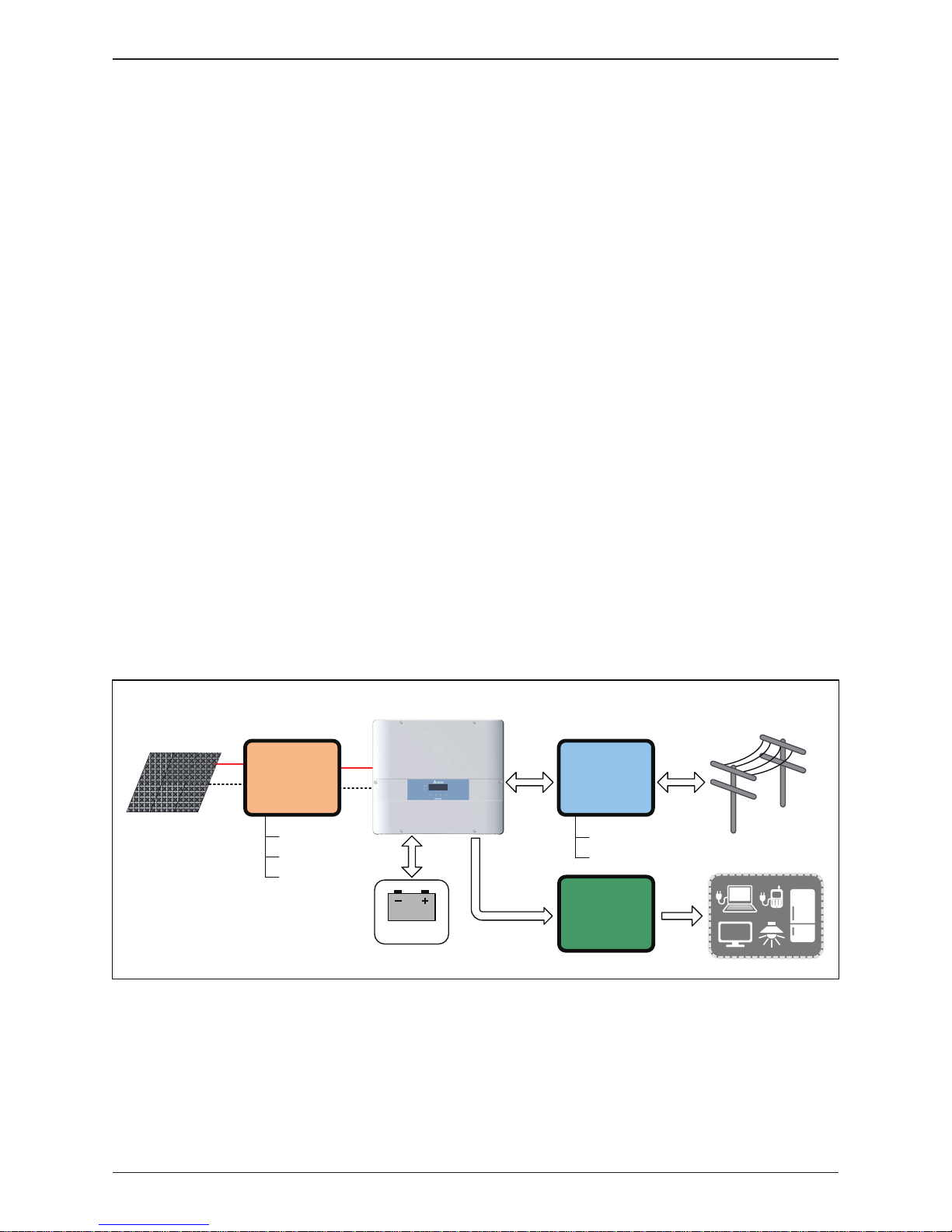
The operation of hybrid inverter is shown as Figure 1-1. Inverter convert the
DC input power supplied from the PV Array and Battery into single phase AC
output power to Grid and Load.
Figure 1-1 : Storage system operation illustration
For more detailed or other related product information, please visit
http://www.deltaww.com
1 General Information
1.1 About this Manual
1.2 Product Description
1.3 Additional Information
PV Array
Electrical Grid
Hybrid Inverter
DC Distribution
box
AC Distribution
box
Surge arrestor
Fuse
DC switch
Surge arrestor
AC breaker
L , N , PE
Install if necessary
AC Distribution
box
Home Load
Battery
General Information
9
Page 10
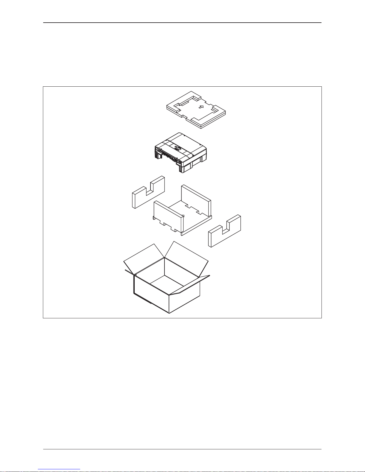
Figure 2-1 : Unpack the inverter
The unpacking procedure of E5 inverter is shown as Figure 2-1.
Unforeseeable events causing damage or movement may occur during shipment.
Please check following items upon receiving your inverter.
• Check the damage on the packaging.
• Check if all the accessories are in the package.
The standard accessories are shown in Figure 2-2 and Table 2-1.
• Check the model number and the serial number on the packaging is identical
with the model number and serial number on the unit itself.
If there is any visible damage to the inverter / accessories or packaging, please
contact your inverter supplier.
2 Product Overview
2.1 Unpack the Inverter
2.2 Checking Unit and Accessories
10
Product Overview
Page 11
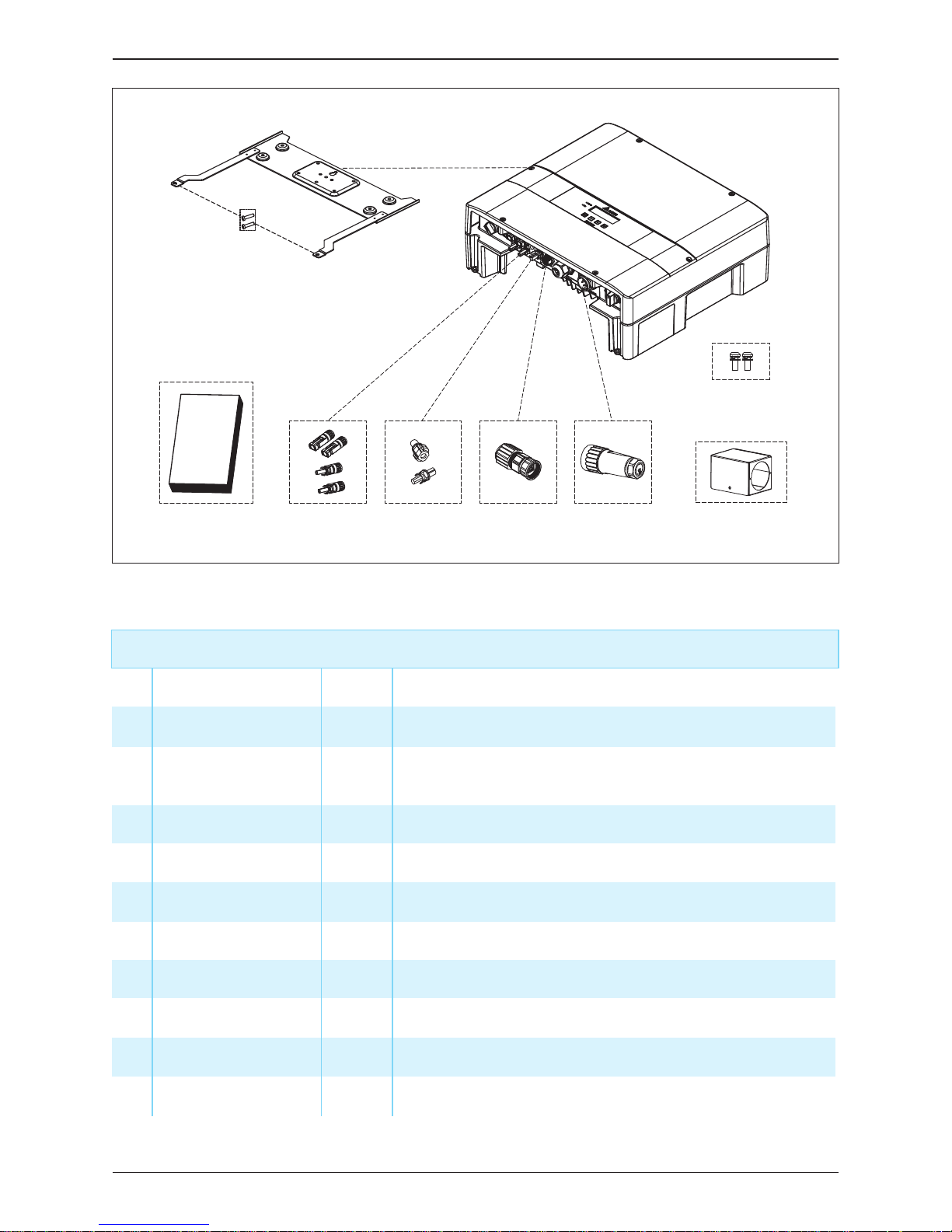
Figure 2-2 : Packing list
E5 Hybrid inverter
Object Qty Description
1 Hybrid Inverter 1 pc
1 pc
E5 hybrid inverter
2 User Manual
The Instruction to provide the information of safety,
Installation, specification, etc.
3
4
5
Table 2-1 : Packing list
①
② ⑥⑤ ③ ④
⑩
⑧
⑨
⑦
6
7
8
9
10 #6-32 Screw 2 pcs To fix the AC plug shield.
1 set
1 set
AC Plug Shield
BT Connector
Exterior cover for AC Plug
1 pcAC Plug Connector for AC connection
Connector for Battery connection
DC Connector 2 sets Connector for PV array connection
RJ45 Connector 1 pc Connector for Battery communication
Mounting Bracket 1 pc To mount the hybrid inverter on the wall.
M4 Screw 2 pcs To fix the hybrid inverter on the wall.
11
Product Overview
Page 12
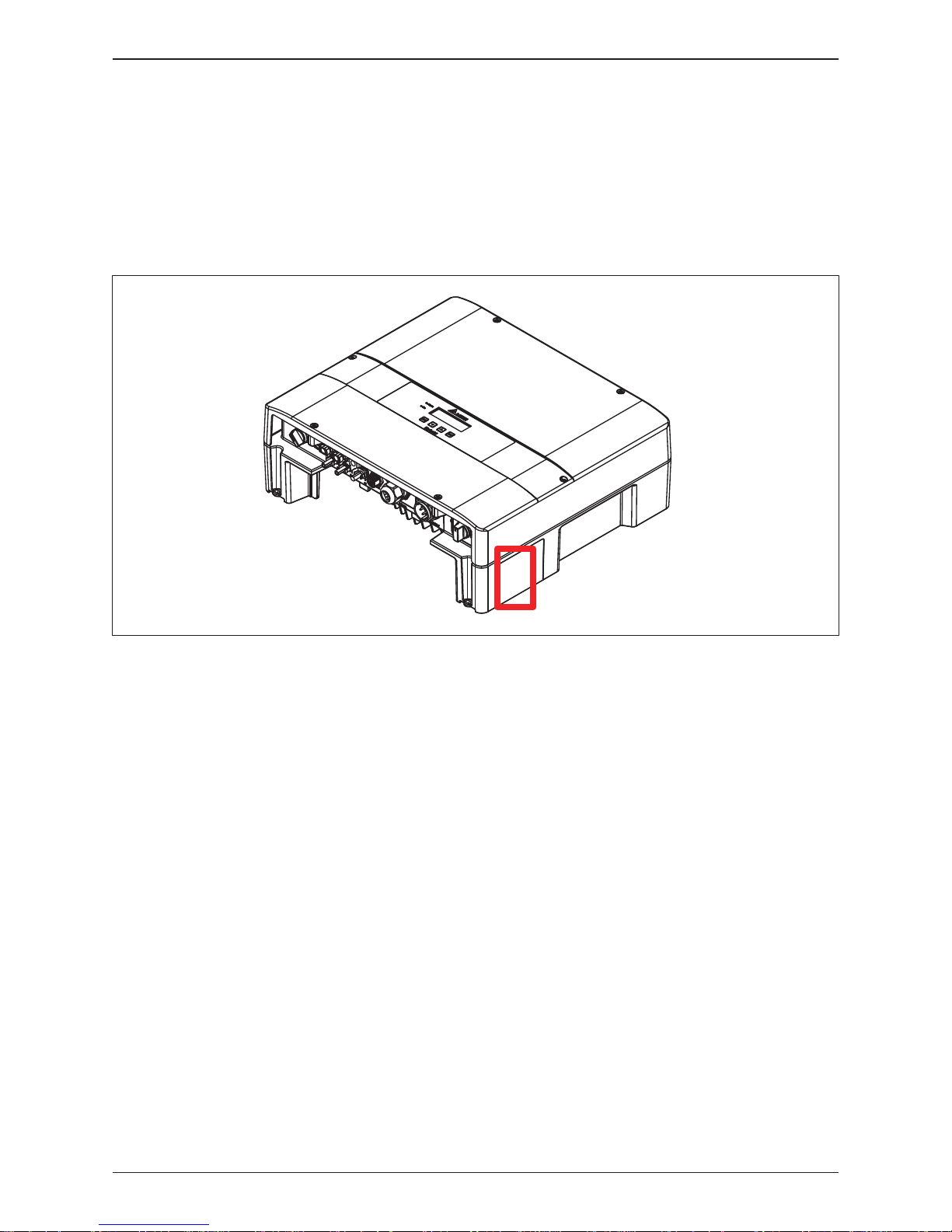
Please refer to Figure 2-3 for the location of product label. You can identify the
model number and the specifications by the information on the product label.
In Australia and New Zealand, users can also identify the supported Demand
Response Modes (DRMs) of E5 here.
Figure 2-3 : Product label
2.3 Product Label
12
Product Overview
Page 13
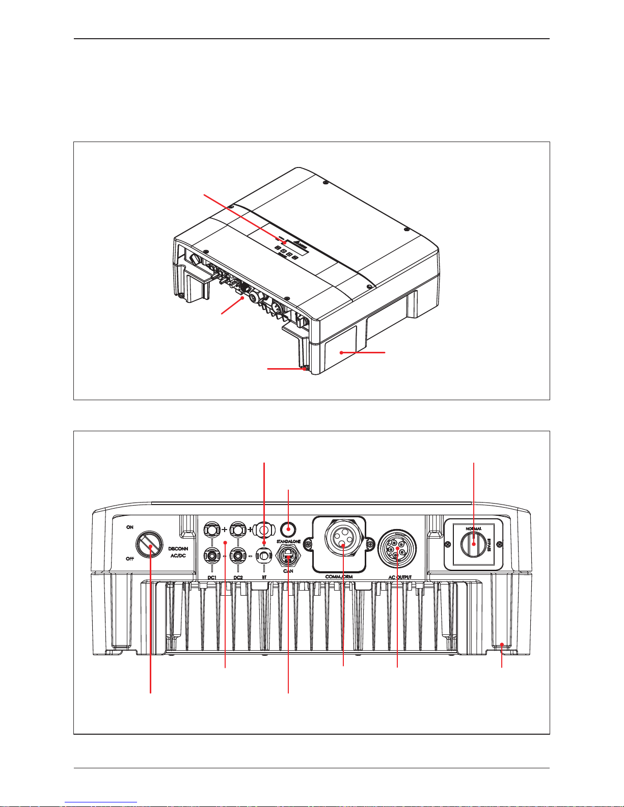
LCD / LED Display
and Buttons
Label
Grounding Hole
Input /
Output
Interfaces
The Inverter’s exterior objects are shown in Figure 2-4. The detailed input /
output interfaces illustration is shown in Figure 2-5.
Figure 2-4 : Inverter’s exterior objects
2.4 Exterior Objects
Figure 2-5 : Input / output interface
Manual bypass switch
Standalone Button
AC Connector
4 port + PE
RS-485 * 2
EPO
Dry Contact
Digital Input/ DRMs
PV Connector
(2 string)
AC / DC Switch
Grounding Hole
BT Connector
CAN (RJ45)
13
Product Overview
Page 14
This unit is designed to be wall-mounted. Please ensure the installation is
perpendicular to the floor and the AC plug at the bottom. Do not install the
device on a slanting wall.
To mount the inverter on the wall, please follow the procedure below:
1. Screw the mounting bracket on the wall with 8 M6 Phillips head screws.
Please refer to Figure 3-3.
2. Attach the inverter to the mounting bracket.
3. Use Hex Wrench fixing the inverter with 2 M4 Hexagon Socket screws.
Please refer to Figure 3-4.
3 Installation
- The unit should not be installed in a direct sunlight.
- Servicing of batteries should be performed or supervised by personnel
knowledgeable about batteries and the required precautions.
CAUTION !
WARNING !
- Do not install the unit near or on flammable surfaces.
- Please mount the unit tightly on a solid / smooth surface.
14
Installation
Page 15
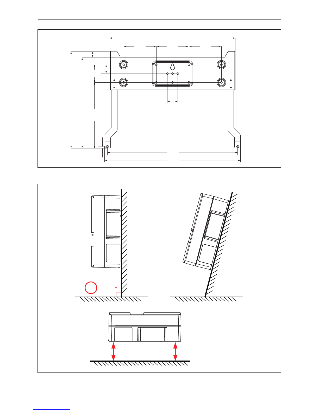
Figure 3-1 : Mounting bracket dimension
Figure 3-2 : Recommended installation
90
Not
Recommended
Not
Recommended
Keep >30 cm from floor and
water if installed this way
424
110
110
110
35
440
327
30
60222
20
5
302
458
15
Installation
Page 16
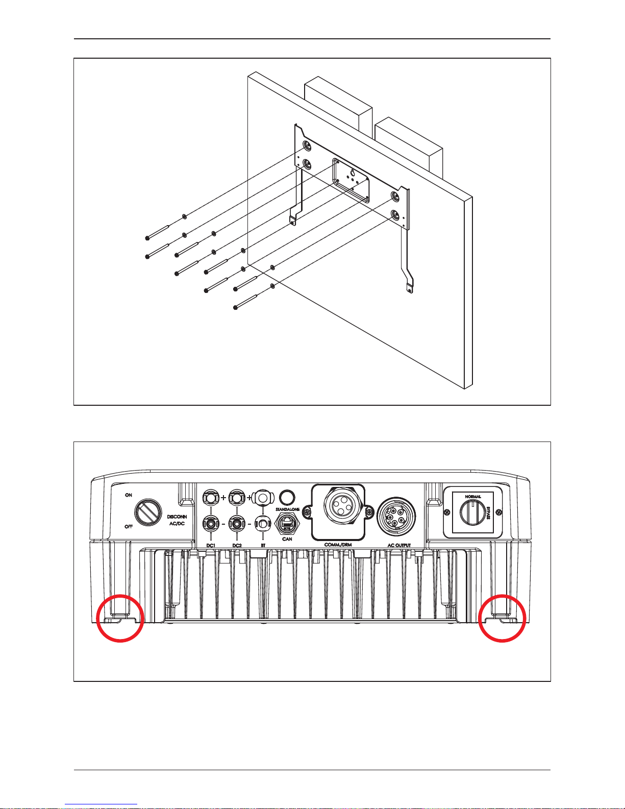
Figure 3-4 : Attach to the bracket and fasten with screws
Figure 3-3 : Screw the mounting bracket
M4 Screw M4 Screw
16
Installation
Page 17
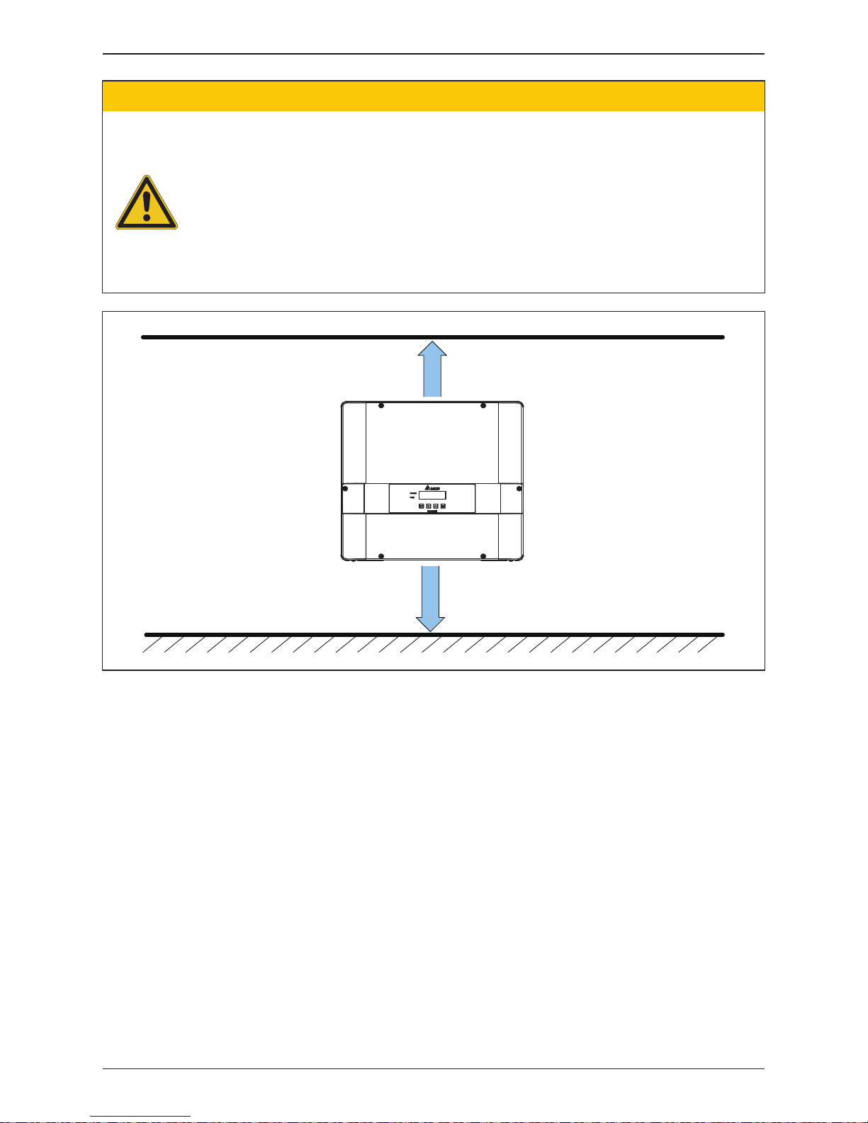
> 20 cm
> 20 cm
Figure 3-5 : Proper installation gaps
- The bracket supplied with the unit is specially designed and should be the only
mounting device used for the unit.
- It is recommended to install the inverter in a suitable location which offers
non-obscured and safe access, in turn ensuring easy access for service and
maintenance.
- Please install hybrid inverter at an eye level to allow easy observation for operation
and parameter setting.
- Ambient temperature -25° C~60° C. (power de-rating above 40° C)
CAUTION !
17
Installation
Page 18

• Please use PVC insulated outdoor power cables and connected to the inverter
through a specific certified connector.
• Please use ungrounded PV power system due to E5 does not have galvanic
isolation between the DC-input, Battery and AC-output.
• E5 has array insulation resistance measuring function. Please ensure the
insulation resistance of array is over 550k ohm.
• There are two earth bonding methods for E5.
You can ground the inverter by enclosure grounding hole that shown in Figure 2-4
or by PE terminal of AC plug. Please use at least one grounding method to
avoid electric shock.
• Inverter can support DC inputs in parallel connection (1 MPP tracker) or
separate connection (2 MPP trackers).
• The overview of wiring please refers to Figure 4-1.
4 Wiring
4.1 Preparation Before Wiring
WARNING:SHOCK HAZARD!
- Whenever a PV array is exposed to sunlight, a shock hazard may exist due to
output wires or exposed terminals. To reduce the risk of shock during installation,
cover the array with an opaque (dark) material and ensure that the AC/DC
disconnect switch in the inverter is set to OFF before commencing any wiring.
18
Wiring
Page 19

Communication
Wiring CAN and RS-485
2
4
PV Wiring
Parallel or
Separate
+
-
+
-
+
-
3
BT Wiring
1
AC Wiring
L(Grid)
PE
L(Load)
N(Grid)
N(Load)
Figure 4-1 : Connection of system for floating solar array and battery
19
Wiring
Page 20

It is recommended to install a 30A or 32A upstream circuit breaker between AC
side and inverter side for over current protection. The AC cable must be jacked
and meet the specifications in Table 4-1.
Model Current Rating Recommended TorqueWire Size
25 AE5
0.7 N・m
Table 4-1 : AC input cable requirement
5 - 8mm
2
4.2
AC Connection
WARNING !
- Before commencing AC wiring, please ensure AC breaker is switched off.
4.2.1
Required Protective Devices and Cable Cross-sections
The AC wiring system diagram is shown in Figure 4-2. It recommended users
follow the diagram connecting the AC wiring. The connection between Grid N
and Load N is used to eliminate the floating voltage between Load N and PE.
E5 can still works without the Grid N and Load N connection.
4.2.2 AC Connection
PE
PE
L
N
N L N L
RCD
Backup Power
loads
AC load
P1
Distribution PanelDelta E5
Grid
Load
L
N
PE
L
N
Figure 4-2 : AC connection
20
Wiring
Page 21

- Make sure to use the proper size of AC cable.
- Please choose the terminals as shown in Figure 4-3 for wires crimping.
- Failed to follow these instructions may cause AC plug damage.
CAUTION!Machine and equipment damage may occur.
Figure 4-3 : Terminal for wire crimping
The AC wiring system diagram is shown in Figure 4-3. It recommended users
follow the diagram connecting the AC wiring. The connection between Grid N
and Load N is used to eliminate the floating voltage between Load N and PE.
E5 can still works without the Grid N and Load N connection.
4.2.3 AC Plug Assembly
Follow the steps below to strip the wires before assembling the AC plug as
shown in Figure 4-4 :
• Remove 55 mm (2.2 inch) of AC cable outer jacket.
• Trim the L-N(Grid), L-N(Load) wire to 52.5 mm (2.0 inch).
• Strip 10 mm (0.5 inch) of insulation from all wires ends.
• Crimp terminals for all wires.
Figure 4-4 : Striping the wires
outer jacket
12mm
[0.5in.]
52.5 mm
[2.0 in.]
55mm[2.2in.](PE)
21
Wiring
Page 22

Assemble the AC plug and wires as the procedures shown in Figure 4-5.
The sequence of L(Grid), N(Grid), L(Load), N(Load) and PE must be connected
correctly. The AC voltage should be L-N 230 Vac ± 10%.
1. Fixed this part
2. Rotate to loosen
the AC plug
3. Depart the AC plug.
4. Insert the wires
5. Tighten the screws to
fixed the wires..
5. Reassemble the AC plug
Inverter
7. Rotate to tighten the plug
6. Connect the AC plug
to inverter
8. Rotate the gland to
fix wires
Figure 4-5 : AC plug illustration for E5
L(Grid)
PE
L(Load)
N(Grid)
N(Load)
Cable
Cable
Align the biggest latch of the AC plug and socket
Socket AC plug
Cable
22
Wiring
Page 23

AC plug shield is a cover to prevent users loosens the AC plug easily and cause
electrical shock. To assemble the AC plug shield, please follow the instruction
below.
1. There has a slot at well installed AC plug's upper side. Please refer to the
dotted line in Figure 4-6. Assemble 2 metal parts of AC plug shield at this slot.
2. Use 2 #6-32 screws to fix the metal parts.
(The torque of the screw: 8±1 Kgf-cm)
4.2.4 AC Plug Shield Assembly
Figure 4-6 : AC Plug Shield Assembly
23
Wiring
Page 24

Type of limit E5
Total input power 5.5 kW
DC1 / DC2 2.75 kW / 2.75 kW
Table 4-2 : Maximum rating of input power
- The maximum open circuit voltage of PV array should not exceed 600Vdc.
- It is recommended to install an over current protection device between PV
array side and inverter side.
- Any device installed between PV array and inverter must have capability to
withstand the open-circuit voltage and short-circuit current of PV array.
- The input power to the inverter should not higher than the rated power shown
in Table 4-2.
CAUTION !
WARNING !
- When undertaking DC wiring, please ensure the correct polarities are connected.
- When undertaking DC wiring please ensures that the power switch on the PV
array is OFF.
Model Current Rating Wire size
E5 DC 12A 2 - 3mm
2
/ 14 AWG
Table 4-3 : Cable size
4.3 DC Connection (from PV Array)
Figure 4-7 : DC plug wiring illustration
DC wiring polarities are divided into positive and negative, which is shown in
Figure 4-7. The connection shall be coherent with the indication marked on
inverter.
PV-KST 4/6 ⅡPV-KBT 4/6 Ⅱ
24
Wiring
Page 25

Battery wiring uses 1 pair of Phoenix connector. Please follow the instructions
below to assemble the connector.
1. Put the stripped wire into the cable adapter
2. Lock it.
3.
Attach the bottom part of the cable adapter to the upper part of the cable adapter.
4. Rotate and tighten them.
Figure 4-8 depicts the procedure listed above.
The connection shall be coherent with the indication marked on inverter.
Battery box’s assembly please refers to battery box quick install guide.
4.4 Battery Connection
WARNING !
-
When undertaking battery wiring, please ensure the correct polarities are connected.
-
When undertaking battery wiring, please ensures that the power switch on the battery
side is OFF.
-
There is an internal disconnection device and a battery management system (BMS)
in the battery box. It's not necessary to install another disconnection device
between inverter and battery box.
-
Servicing of batteries should be performed or supervised by personnel knowledgeable
about batteries and the required precautions.
Model Current Rating Wire size
E5 DC 40A 8 - 9mm
2
/ 8 AWG
Table 4-4 : Battery cable size
Figure 4-8 : Assemble the Battery Connector
18mm
25
Wiring
Page 26

The communication interface between E5 and battery is CAN bus. The physical
connection type is RJ45 socket. To meet the IP65 class, please use the RJ45
connector of E5 accessory. Figure 4-9 describes the parts of RJ45 connectors.
To assemble the connector, please follow the procedure below:
1. Insert the sealing nut, seals, and support into the cable assembly.
(Cable OD range: 5.0 ~ 6.5 mm.)
2. Connect the sealing nut on the half-finished goods and screw tightly.
(Sealing nut torsion value range: 5~15 kgf-cm)
4.5 CAN Connection
Figure 4-9 : Overview of RJ45 Connectors
Figure 4-10 : Assembling Procedure of RJ45 Connectors
26
Wiring
Page 27

RJ-45 cable without cable connector boots plug cover (soft plastic) is
recommended as indicated in Figure 4-11.
The terminal configuration of CAN connection as specified in Table 4-5.
Figure 4-11 : Suitable cables for RJ45 connector
Pin Assignment
1 VCC (+24V)
2 GND
3 Battery Fault Sensor
4 CANH
5 CANL
6 N/A
7 N/A
8 N/A
Table 4-5 : RJ45 socket pin assignment of CAN
27
Wiring
Page 28

Figure 4-12 : Communication module
Please refer to Figure 4-12 for the Communication Module illustration.
The module provides VCC, RS-485, dry contact, and EPO terminals for
different use.
EPO & Digital Inputs & DRMs
Dry Contact
RS
VCC
GND
-485
Terminal
Resistor
4.6 Communication Module Connections
+
+
-
-
+
+
-
-
The pin definition and data format of RS-485 is shown in Table 4-6.
Installers should switch ON the terminal resistor when single inverter is installed.
Pin Function Data Format
1 VCC (+24V)
Baud rate: 19200
Data bits: 8
Stop bit: 1
Parity: N/A
2 GND
3 DATA+
4 DATA5 DATA+
6 DATA-
Table 4-6 : Pin definition and data format of RS-485
4.7 RS-485 Connection
1
2
3
4
5
6
28
Wiring
Page 29

Communication Module has 1 set of emergency power off function (EPO).
When the VCC and INV OFF pins are short-circuited, inverter will shut down
immediately. The module also provides 6 sets of digital input function (K1~K6).
Please refer to Table 4-7 for the digital input definition. The suitable electric wire
is 30-16AWG.
In Australia and New Zealand, the Demand Response Modes (DRMs) are
also use digital input function to assert. The definition is different from normal
digital input function; please refer to Table 4-8 for the DRMs pin definitions.
4.8 Digital Input / DRM & EPO Functions
Short Inverter’s action
VCC & INV OFF Emergency power off (EPO)
VCC & K1 0% active power
VCC & K2 Maximum 30% active power
VCC & K3 Maximum 60% active power
VCC & K4 Maximum 100% active power
VCC & K5 Reserved
VCC & K6 Reserved
Table 4-7 : Definition of digital input & EPO functions
Short Inverter’s action
VCC & INV OFF DRM 0 (Disconnect from grid)
VCC & K1 DRM 5 (0% generate power)
VCC & K2 DRM 6 (50% generate power)
VCC & K3 DRM 7 (75% generate power and sink reactive power)
VCC & K4 DRM 8 (100% generate power)
VCC & K5 Reserved
VCC & K6 Reserved
Table 4-8 : Definition of DRMs for Australia and New Zealand
Communication Module has 1 set of Dry Contact. The trigger condition of this
function can be customized by Installer. When the function is triggered, the output
two ports will be short-circuited. Please refer to section 5.3.8 Install Settings for
more details about trigger condition assignation.
4.9 Dry Contact Connection
29
Wiring
Page 30

E5 can be used in single-phase parallel combination system. In this application,
inverter may be parallel connected to a same AC grid. It recommended connecting
the RS-485, EPO, and digital input together of all E5s for an easily and immediately
remote control. Please refer to Figure 4-13, Figure 4-14 and Figure 4-15 for the
illustration of multiple inverters combination.
In Australia and New Zealand, the max valid combinations number of E5s is 3.
Please do not install more than 3 E5s at same point of common coupling.
4.10 Multiple inverter combinations
Figure 4-13 : Single-phase parallel combinations
Figure 4-14 : Multiple inverters RS-485 connection
L (Grid)
ID: 1 ID: 2 ID: N
N (Grid)
Data Format:
Baud rate: 9600, 19200 , or 38400
Data bits: 8
Stop bit: 1
Parity: N/A
RS485/USB
or
RS485/RS232
Terminal Resistor
120Ω(1/2W)
DATA+ to DATA-
Terminal Resistor
120Ω(1/2W)
DATA+ to DATA-
30
Wiring
Page 31

SW
INV_1
(VCC)V1
K0 (EPO)
K1 (0% Power)
K2 (30% Power)
K3 (60% Power)
K4 (100% Power)
K5
K6
INV_2
(VCC)V1
K0 (EPO)
K1 (0% Power)
K2 (30% Power)
K3 (60% Power)
K4 (100% Power)
K5
K6
INV_N
(VCC)V1
K0 (EPO)
K1 (0% Power)
K2 (30% Power)
K3 (60% Power)
K4 (100% Power)
K5
K6
EPO Button
Figure 4-15 : EPO & Digital input & DRMs parallel connection
31
Wiring
Page 32

5 Turning On the Hybrid Inverter
WARNING:BURN HAZARD!
- The enclosure temperature may exceed 70°C while inverter is operation.
A dangerous burn hazard is present in this situation.
5.1 LCD Flow Chart
E5 includes a 4x20 character type LCD display and 2 LED to indicate inverter’s
status. Table 5-1 reveals more information about inverter status and LED
indicator.
The following section will introduce the functions that can be adjusted by users
through the LCD panel. When you are adjusting settings, LCD panel will change
the display cursor from “►” to “ ”.
Meter
Energy Log
Event Log
Inverter Information
General Setting
Operation Mode
Function Setting
Install Setting
5.3.1
5.3.2
5.3.3
5.3.4
5.3.5
5.3.6
5.3.7
5.3.8
Meter
Energy Log
Event Log
Information
►
General Settings
Operation Mode
Function Settings
Install Settings
ESC : Exit Menu
UP : Move Up
Down : Move Down
ENT: Enter or Confirm
LED Indicator (GRN)
LED Indicator (RED)
Figure 5-2 : User Interface
Figure 5-1 : Menu page
32
Turning On the Hybrid Inverter
Page 33

Condition Green LED
Countdown or Standalone FLASH
Power ON ON
Error or Fault OFF
AC/DC switch off OFF
Bootloader mode FLASH
Red LED
OFF
OFF
ON
OFF
Table 5-1 : LED indicator
5.2 First Startup
At first startup, you have to supply AC power and turn on the AC/DC switch.
After a while, LCD display will come live and ask you to set language, country
(electricity regulation), and operation mode.
When all the settings are done, you can see Home Page showing on display.
Now you can supply DC power and wait inverter doing self-test and starting
operation.
In the case of no AC power, you can turn on DC power first then switch on
the AC/DC switch and press the standalone button about 1 second. If DC side
has enough voltage and power, inverter will turn on after a while. In this condition,
inverter is forced operating in standalone mode.
You can also turn on E5 by using battery power. Switch on AC/DC switch and
wake up the battery, waiting about 30 seconds you will see inverter starting
to work in standalone mode. The method of wake up battery will be described
in battery box’s manual.
Figure 5-3 : Country and language settings for first startup
First Startup
Select Country,
AU/NZ
Germany LV
NL
►
Select Language,
English
Deutsch
Nederlands
►
Set Operation Mode,
Self consump.
Peak cut
Selling first
►
Country:
Mode:
YesNo
Germany LV
Self-consump.
ENT
ESC
ENT
ESC
ENT
ESC
33
Turning On the Hybrid Inverter
Page 34

Figure 5-4 : Home page
When inverter is operating normally, the LCD display will show home page on
screen. In this page, you can get the information about inverter operation
status, PV power, BT power (charge/ discharge), load power, and grid power
(purchase/ selling).
Pressing any key in home page can you enter menu page. There are 8 branches
in the menu. The following chapters will introduce you these subpages.
5.3 Home Page
In meter page, you can get more detail information about PV, BT, Load, and
Grid power.
5.3.1 Meter
Figure 5-5 : Power meter page
2014.12.13 13:50
Status: On Grid
PV►1022W Load►1695W
BT◄1100W Grid►1573W
PV power
BT power
Load power
Grid Power
Inverter Status
Day-Time
BT►: Discharge
BT◄: Charge
Grid►: Purchase
Grid◄: Selling
Load Power:
Load Voltage:
Load Current:
Frequency:
3000
230
13.0
50.00
W
V
A
Hz
BT SOC:
BT Charge:
BT Voltage:
BT Current:
100
+/- 3000
200
39.5
%
W
V
A
250
10.0
2500
DC1 DC2PV
V
I
P
250
10.0
2500
V
A
W
Grid Power:
Grid Voltage:
Grid current:
Frequency:
+/- 3000
230
12.0
50.00
W
V
A
Hz
ENT
Meter
Energy Log
Event Log
Inverter Info.
►
34
Turning On the Hybrid Inverter
Page 35

Energy log can be separate into load power log and PV power log; each log
can record its own day / month / year power.
5.3.2 Energy Log
This page can records the last 30 events of error and fault. The latest event
will be revealed on the top.
5.3.3 Event Log
Figure 5-6 : Energy log flow chart
Figure 5-7 : Event log flow chart
Meter
Energy Log
Event Log
Inverter Info.
►
Load Power
PV Power
►
L-Day
2013.02.23
2013.02.22
2013.02.21
12
11
15
kWh
kWh
kWh
L-Month
2013.11
2013.10
2013.09
300
360
333
kWh
kWh
kWh
L-Year
2013
2012
2011
3650
3325
3360
kWh
kWh
kWh
Load Power
PV-Day
2013.02.23
2013.02.22
2013.02.21
12
11
15
kWh
kWh
kWh
PV-Month
2013.11
2013.10
2013.09
300
360
333
kWh
kWh
kWh
PV-Year
2013
2012
2011
3650
3325
3360
kWh
kWh
kWh
PV Power
ENT
ENT
1. 2013.02.20 15:30
AC Freq High
2. 2013.02.19 09:30
AC Volt Low
Meter
Energy Log
Event Log
Inverter Info.
►
ENT
35
Turning On the Hybrid Inverter
Page 36

This page can helps you to recognize your inverter. There are serial number,
installation date, firmware version, setting country, inverter operation mode,
BT SOH, and BT Capacity information in this page.
Please be noticed that inverter operation mode shown in this page is not the
same as the operation mode set by user. Please refer to 5.3.6 Operation Mode
chapter for more detail information.
5.3.4 Inverter Information
Figure 5-8 : Inverter information page
S/N:
Install:
DSP 1.80
Comm. 1.65
RN11179CB0
2014.10.13
Red. 1.65
ID: 002
Country:
Mode:
BT SOH:
BT Capacity
Germany LV
Self-consump.
100%
6.0kWh
Meter
Energy Log
Event Log
Inverter Info.
►
ENT
In this page you can change display language, time, and RS-485 communication
baud rate.
5.3.5 General Settings
Figure 5-9 : General settings page
General Settings
Operation Mode
Function Settings
Install Settings
►
Language
Date & Time
Baud Rate
►
English
Deutsch
Nederlands
►
2013.10.04 13:50
9600
19200
38400
►
Language Date & Time Baud Rate
ENT
ENT
36
Turning On the Hybrid Inverter
Page 37

Hybrid inverter has 6 normal operation modes for users to choose.
Each mode has different behavior between PV, battery, grid, and home load.
The following are the description of these modes.
In some area, the detail behavior of each operation mode may be different due
to the local electricity regulations.
5.3.6 Operation Mode
Figure 5-10 : Operation mode page
General Settings
Operation Mode
Function Settings
Install Settings
►
Self consump.
Peak cut
Selling first
Charge first
►
Current Setting:
Self consumption
Exit Change
Discharge first
Without BT
►
ENT
ENT
37
Turning On the Hybrid Inverter
Page 38

Self-consumption mode is standard hybrid inverter mode.
In this mode, PV power is supplied in following priority :
1. Supply for home load.
2. Charge the battery until it is full.
3. Feed-in the remaining power to grid.
When there is no PV power, battery starts to discharge and supply home load
until it’s empty.
If you had set the time settings, the behavior of hybrid inverter will change.
We will explain it in 5.3.7 Function Setting chapter.
5.3.6.1 Self-consumption mode
Figure 5-11 : Self-consumption mode current flows
Figure 5-12 : Self-consumption mode behavior
Electrical Grid
Hybrid Inverter
Battery
Input or
output
Charge or
discharge
Input
Output
Home Load
PV Array
19:0012:0007:0000:00 24:00
PV power
PV power used
for home load consumption
Excess PV power
Battery discharges
Home load power usage
38
Turning On the Hybrid Inverter
Page 39

When home load consumption exceeds the Peak Cut Power you set in Function
Setting page, battery will discharge to assist the power usage.
5.3.6.2 Peak cut mode
Figure 5-13 : Peak cut mode current flows
Figure 5-14 : Peak cut mode behavior
Electrical Grid
Hybrid Inverter
Battery
Input or
output
Charge or
discharge
Input
Output
Home Load
PV Array
19:0012:0007:0000:00 24:00
PV power
PV power used
for home load consumption
Excess PV power
Home load power usage
Battery discharges
39
Turning On the Hybrid Inverter
Page 40

Selling first mode is a standard PV inverter mode combining with 6 time settings.
In normal operation, power generated by PV array will all feed-in to home load
and grid. If users have set the time settings, inverter will change behavior in
these time intervals. Please refer to 5.3.7 Function Setting chapter for more
detail about time settings.
5.3.6.3 Selling first mode
Figure 5-15 : Selling first mode current flows
Figure 5-16 : Selling first mode behavior
Electrical Grid
Hybrid Inverter
Battery
Input or
output
Charge or
discharge
Input
Output
Home Load
PV Array
19:0012:0007:0000:00 24:00
PV power
PV power used
for home load consumption
Excess PV power
Home load power usage
40
Turning On the Hybrid Inverter
Page 41

Figure 5-17 : Charge first mode current flows
Figure 5-18 : Charge first mode behavior (general)
Electrical Grid
Hybrid Inverter
Battery
Input or
output
Charge or
standby
Input
Output
Home Load
PV Array
19:0012:0007:0000:00 24:00
PV power
PV power used
for home load consumption
Excess PV power
Home load power usage
In this mode, PV power is supplied for battery charging first. After battery is
fully charged, the remaining PV power then feed-in to home load and grid.
Battery will not discharge in this mode even if there is no PV power.
Users in Australia and New Zealand can charge the battery from grid power by
using this mode due to the permission of electricity regulations. Battery will be
charged by PV or grid with the maximum charge current.
5.3.6.4 Charge first mode
41
Turning On the Hybrid Inverter
Page 42

Figure 5-19 : Charge first mode behavior (for AU & NZ)
19:0012:0007:0000:00 24:00
PV power
PV power used
for home load consumption
Excess PV power
Home load power usage
42
Turning On the Hybrid Inverter
Page 43

In this mode, battery will not be charged any more.
All the PV power is feed-in to home load and grid. Battery keeps discharging
when there is no PV power until it is empty.
5.3.6.5 Discharge first mode
Figure 5-20 : Discharge first mode current flows
Figure 5-21 : Discharge first mode behavior
Electrical Grid
Hybrid Inverter
Battery
Input or
output
Discharge
or standby
Input
Output
Home Load
PV Array
19:0012:0007:0000:00 24:00
PV power
PV power used
for home load consumption
Excess PV power
Battery discharges
Home load power usage
43
Turning On the Hybrid Inverter
Page 44

If your battery was damaged for some reason, you can disconnect the battery
wiring and choose without BT mode. In this mode, hybrid inverter acts like a
basic grid-tie PV inverter.
5.3.6.6 Without battery mode
Figure 5-22 : Without battery mode current flows
Figure 5-23 : Without battery mode behavior
Electrical Grid
Hybrid Inverter
Input or
output
Input
Output
Home Load
PV Array
19:0012:0007:0000:00 24:00
PV power
PV power used
for home load consumption
Excess PV power
Home load power usage
44
Turning On the Hybrid Inverter
Page 45

In addition to the 5 modes above, hybrid inverter still have 3 special modes.
These modes cannot be enabled by user but will be enabled automatically by
inverter in some special condition.
Hybrid inverter changes to standalone mode automatically during a power
outage occur. At this time, grid side is disconnected by inverter and home load
are supported by PV and battery power as much as possible.If the battery is
not connected, only when there has sufficient PV power can inverter enter
standalone mode.
• Standalone mode
5.3.6.7 Special Modes
Figure 5-24 : Standalone mode current flows
Figure 5-25 : Standalone mode behavior
Hybrid Inverter
Battery
Charge or
discharge
Input
Output
Home Load
PV Array
19:0012:0007:0000:00 24:00
PV power
PV power used
for home load consumption
Excess PV power
Battery discharges
Home load power usage
45
Turning On the Hybrid Inverter
Page 46

Although battery stops any action when SOC (state of charge) reach 0%,
the self-discharge phenomenon may still causing SOC lower than 0%.
At this time, hybrid inverter will force battery charging from PV power and grid
power until the battery SOC reaching 30%.
• Forced charge mode
Figure 5-26 : Forced charge mode current flows
Electrical Grid
Hybrid Inverter
Battery
Input or
output
Forced
Charge
Input
Output
Home Load
PV Array
Figure 5-27 : Forced charge mode behavior
19:0012:0007:0000:00 24:00
PV power
PV power used
for home load consumption
Excess PV power
Home load power usage
46
Turning On the Hybrid Inverter
Page 47

In function settings page, you can assign SOC limit, peak cut power, and
BT charge / discharge time interval.
5.3.7 Function Setting
Figure 5-28 : Function Settings page
You can assign the lower limit of battery SOC. Battery will stop discharging
when its SOC reach this limit.
• SOC Limit
Peak cut power is used in peak cut mode. You can assign the peak power of
home load usage from grid. When the home load consumption exceeds this
value, battery will discharge to supply remaining power.
• Peak Cut Power
Time settings can be separated into BT charge time and BT discharge time.
Each setting can set 3 time intervals. These 6 time intervals cannot overlap
with each other.
When the inverter operation mode set to self-consumption or selling first mode,
time settings is enabled. Hybrid inverter will automatically change the mode
to charge first / discharge first in the time intervals you set and return to
self-consumption / selling first mode outside the intervals.
• Time Settings
General Settings
Operation Mode
Function Settings
Install Settings
►
SOC Limit
Peak Cut PWR
Time Settings
►
30%
3kW
BT Charge Time
BT Discharge Time
►
BT Charge Time:
00:00 – 00:00
00:00 – 00:00
00:00 – 00:00
►
BT Charge Time
BT Discharge Time
►
BT Discharge Time:
00:00 – 00:00
00:00 – 00:00
00:00 – 00:00
►
BT Charge Time
BT Discharge Time
ENT
ENT
47
Turning On the Hybrid Inverter
Page 48

- The settings in Install Settings page can only be adjusted by qualified installers or
engineers. Changing these settings may result in damage to the inverter and other
equipment.
CAUTION !
5.3.8 Install Settings
Install Settings page is for installer only.
To enter this page, installer has to key in installer password.
The page includes following functions :
Inverter ID is used to recognized the inverter when you communicating with
it via RS-485.
• Inverter ID
Inverter will measure the impedance between PV array and PE before
connecting to grid. To avoid risk of electrical shock, it’s not recommending to
disable this function.
• Insulation
Each country has its own electricity regulations. The hybrid inverter can meets
more than one electricity regulations. Installer must select the country correctly.
• Country
Installer can choose the trigger condition of dry contact. The explanations of
these conditions are shown in following table.
• Dry Contact
This option is used to clear the battery power fault message. Before clearing
the fault message, please make sure the battery has been repaired.
• Clear BT PF
Setting Dry Contact Trigger Timing
Disable No action.
On Grid Inverter is connecting to grid.
Insulation Insulation test fail.
Alarm Any error or fault occurs.
Any fault occurs.
Table 5-2 : Dry contact trigger condition
Error Any error occurs.
Fault
This function is currently used in Germany only. Installer in Germany should
set the PV array capacity and enable this function. The maximum feed-in power
to grid will be limited at a percentage of PV array capacity. Installers can set
the various limit percentage to meet the local electricity regulation.
• Subsidy Function
48
Turning On the Hybrid Inverter
Page 49

If you connect the inverter to a remote controller via Wi-Fi interface, you may
use these functions to reset the Wi-Fi module settings.
• Wi-Fi Settings
This option is used to return factory settings. The entire energy log will be
cleared. Please use it with caution.
• Return to Factory
Figure 5-29 : Install Settings page
General Settings
Operation Mode
Function Settings
Install Settings
►
Password
****
Setting ID:
ID = 0
02
Inverter ID:
Insulation:
Country:
Dry Cont.
►
002
ON
Germany LV
Insulat.
Inverter ID:
Insulation:
Country:
Dry Cont.
►
AU/NZ
AU/NZ 2005
Germany LV
NL
►
002
ON
Germany LV
Insulat.
Inverter ID:
Insulation:
Country:
Dry Cont.
►
002
ON
Germany LV
Insulat.
Clear BT PF
Subsidy Function
Wi-Fi Settings
Return to Factory
►
BT Power Fault
has been cleared!
Clear BT PF
Subsidy Function
Wi-Fi Settings
Return to Factory
►
Mode:
PV capacity:
►
ON
Feed-in %: 100%
5.0 kW
Clear BT PF
Subsidy Function
Wi-Fi Settings
Return to Factory
►
Inverter ID
Country
Dry Contact
Clear BT PF
Subsidy Function
Wi-Fi Settings
Disable
On Grid
Insulat.
Alarm
►
Return to Factory ?
Yes / ►No
Clear BT PF
Subsidy Function
Wi-Fi Settings
Return to Factory
►
Return to Factory
Reset IP Address
Reset Password
Reboot Wi-Fi
Reset User Settings
►
ENT
ENT
49
Turning On the Hybrid Inverter
Page 50

In order to ensure the normal operation of inverter, please check and clean the
unit regularly. Once there are any impaired or loose parts, please contact your
inverter installer.
If the hybrid inverter was damaged and cannot supply the power to home load,
please turn off the AC/DC switch at bottom left and turn on the manual bypass
switch at bottom right to keep the power supply to home load via grid.
Please be noticed that when you turn on the manual bypass switch, grid and
home load are forced connected together. In this case, if grid fault occurred,
inverter will stop supplying any power to grid and home load for avoid electrical
shock of maintainer.
6 Maintenance
Warning!Electric Shock
- Before any maintenance, please make sure you are well insulated to avoid
risk of electric shock.
50
Maintenance
Page 51

ERROR
MessageCode Cause Action
7 Error message and Trouble Shooting
AC Freq High
Grid frequency over the limit of
electricity regulation.
Check the grid frequency.
If grid frequency is not in acceptable range,
contact the utility operator to modify it.
If grid frequency lies in acceptable range
but the error still exist, please contact your
inverter supplier.
E01
AC Freq Low
Grid frequency under the limit
of electricity regulation.
Check the grid frequency.
If grid frequency is not in acceptable range,
ask the utility operator to modify it.
If grid frequency lies in acceptable range
but the error still exist, please contact your
inverter supplier.
E02
Grid Quality
Grid harmonic distortion
>8.5% and >2.2s
Check AC wiring; keep the wire short and
straight.
Contact the utility operator to improve the
grid quality.
If the grid quality is good but the error still
exist, please contact your inverter supplier.
E07
No Grid
Grid voltage <20V or voltage
half-cycle > 50ms
Check the triggering of upstream circuit
breaker.
Check the wire connection between inverter
side and grid side.
Contact the utility operator for the information
about power failure.
E09
AC Volt Low
Grid voltage under the limit of
electricity regulation.
Check the grid voltage.
If grid voltage is not in acceptable range,
ask the utility operator to modify it.
If grid voltage lies in acceptable range but
the error still exist, please contact your
inverter supplier.
E10
AC Volt High
Grid voltage over the limit of
electricity regulation.
Check the grid voltage.
If grid voltage is not in acceptable range,
ask the utility operator to modify it.
If grid voltage lies in acceptable range but
the error still exist, please contact your
inverter supplier.
E11
AC Volt High
Grid voltage over the limit of
electricity regulation.
Check the grid voltage.
If grid voltage is not in acceptable range,
ask the utility operator to modify it.
If grid voltage lies in acceptable range but
the error still exist, please contact your
inverter supplier.
E12
51
Error message and Trouble Shooting
Page 52

ERROR
MessageCode Cause Action
AC Volt High
Grid voltage over the limit of
electricity regulation.
Check the grid voltage.
If grid voltage is not in acceptable range,
ask the utility operator to modify it.
If grid voltage lies in acceptable range but
the error still exist, please contact your
inverter supplier.
E13
Solar1 High
DC1 voltage > 600V
(more than 0.1s)
Disconnect the DC1 input and check the
PV array voltage.
If the PV array voltage still over 600V,
please contact the PV array supplier.
If the PV array voltage is fine but the error still
exist, please contact your inverter supplier.
E30
Solar2 High
DC2 voltage > 600V
(more than 0.1s)
Disconnect the DC2 input and check the
PV array voltage.
If the PV array voltage still over 600V,
please contact the PV array supplier.
If the PV array voltage is fine but the error still
exist, please contact your inverter supplier.
E31
Insulation
PV array impedance in either
input < 550 kohm
Check the insulation of DC input wiring.
Check the string for ground faults.
If the insulation of DC wiring is fine but the
error still exist, please contact your inverter
supplier.
E34
Table 7-1 : Error Message
52
Error message and Trouble Shooting
Page 53

Fault
MessageCode Cause Action
DC Injection
DC component in grid current
over the limit
Check the power supply line for direct
current.
Contact the utility operator to improve the
grid quality.
F01
Temp High
Internal temperature too high
to cause power output < 5%
Check the temperature of installation
environment.
Contact your inverter supplier.
F05
HW NTC1 Fail
Internal fault Contact your inverter supplier.F06
Temp Low
Internal temperature < -25℃
Check the temperature of installation
environment.
Contact your inverter supplier.
F07
HW NTC2 Fail
Internal fault Contact your inverter supplier.F08
HW NTC3 Fail
Internal fault Contact your inverter supplier.F09
HW NTC4 Fail
Internal fault Contact your inverter supplier.F10
DC RLY Fail Internal device fault Contact your inverter supplier.F13
HW DSP ADC1
Internal fault Contact your inverter supplier.F15
HW DSP ADC2
Internal fault Contact your inverter supplier.F16
HW DSP ADC3
Internal fault Contact your inverter supplier.F17
HW Red ADC1
Internal fault Contact your inverter supplier.F18
HW Red ADC2
Internal fault Contact your inverter supplier.F19
HW COMM2 Internal fault Contact your inverter supplier.F22
HW COMM1 Internal fault Contact your inverter supplier.F23
Ground Cur. Residual current over the limit
Check the insulation of DC input wiring.
Check the string for ground faults.
F24
RCMU Fail Internal device fault Contact your inverter supplier.F27
RLY Short Internal device fault Contact your inverter supplier.F28
RLY Open Internal device fault Contact your inverter supplier.F29
Bus Unbal. Internal fault Contact your inverter supplier.F30
HW Bus OVR Internal fault Contact your inverter supplier.F31
HW Eff.
Inverter efficiency < 70% or
> 130%
Contact your inverter supplier.F20
53
Error message and Trouble Shooting
Page 54

Fault
Message Cause Action
HW Bus OVR Internal fault Contact your inverter supplier.
HW Bus OVR Internal fault Contact your inverter supplier.
AC Cur. High
Grid current >135% rated and
keep over 50ms
Contact your inverter supplier.
AC Cur. High
Grid current >125% rated and
keep over 5s
Contact your inverter supplier.
HW CT A Fail Internal device fault Contact your inverter supplier.
HW AC OCR
AC current over the limit
20 times within 2s
Check AC and DC wiring for ground faults.
Inverter may be struck by the lighting.
Check the whole wiring of hybrid system.
If this fault occurs often, please contact
your inverter supplier.
SA OPP System overload
In standalone mode, PV and BT power is
insufficient to supply the home load.
Please reduce the load.
HW ZC Fail Internal fault Contact your inverter supplier.
Solar 1 OCR
DC1 current > 135% rated and
keep over 0.2s
Contact your inverter supplier.
BT OVP
BT UVP
Battery system internal fault Contact your inverter supplier.
Battery system internal fault Contact your inverter supplier.
BT OTP
BT UTP
Battery system internal fault Contact your inverter supplier.
Battery system internal fault Contact your inverter supplier.
BT OCP Battery system internal fault Contact your inverter supplier.
Battery system internal fault Contact your inverter supplier.BT CVI
BT TF Battery system internal fault Contact your inverter supplier.
Battery system internal fault Contact your inverter supplier.
Loss communication between
inverter and battery over 10
seconds.
Check CAN connection between inverter
and battery.
Solar 2 OCR
DC2 current > 135% rated and
keep over 0.2s
Contact your inverter supplier.
Solar 1 OCR
DC1 current > 140% rated and
keep over 0.1s
Contact your inverter supplier.
Solar 2 OCR
DC2 current > 140% rated and
keep over 0.1s
Contact your inverter supplier.
Table 7-2 : Fault Message
BT PF
HW COMM BT
Code
F33
F35
F36
F37
F42
F45
F48
F50
F60
F97
F98
F99
F100
F101
F102
F103
F61
F70
F71
F104
F112
54
Error message and Trouble Shooting
Page 55

If it is necessary to put the device out of operation for maintenance or storage,
please follow the procedures below:
At inverter side:
1. Switch off the AC/DC switch and wait for display turning off.
2. Switch the manual bypass switch to normal.
3. Wait for E5’s display panel and battery box’s LED indicator light off.
At wiring side:
4. Switch off AC power line breaker to disconnect from grid.
5. Switch off DC power line breaker to disconnect from PV array.
6.
Use proper voltmeter to check that the AC and DC power are truly disconnected.
7. Remove the AC, DC, and battery wiring.
8. Remove the communication module RS-485 connection from the computer
connection.
Now you may unload the inverter.
8 De-Commissioning
WARNING !
-
To avoid injuries, please follow the procedures to unload the inverter.
55
De-Commissioning
Page 56

Model
GENERAL
Enclosure
Operating temperature
Relative humidity
Galvanic isolation
Safety class
Maximum input power
Recommended PV power range
Nominal voltage
Operating voltage
Startup voltage
Startup power
MPP tracker
Absolute maximum voltage
Full power range
E5
Mounting bracket
Aluminum with powder coating
-25℃~60℃ full power up to 40℃
0% – 100% non-condensing.
Operating Altitude 0 to 2000m (0 to 6666 ft.)
NO
Environmental category Outdoor, wet locations
Protection degree IP65 (Electronics)
Pollution degree Internal : II, External : III
Overvoltage category AC output :III, DC Input :II
Maximum backfeed
current to the array
0
Class I metal enclosure with protective earth
Weight
Dimensions(W*H*D) 510 × 445 × 177mm
Connectors Weather resistant connectors
Audible noise < 40dB
5.5kW
5kW‒6kW
370Vdc
100Vdc – 550Vdc
> 125Vdc
30W
220Vdc‒450Vdc
1 MPP tracker (Parallel connection)
2 MPP trackers (Separate connection)
600Vdc
DC INPUT (Solar side)
9 Technical Data
27kg
Technical Data
56
Page 57

Model
DC INPUT (Solar side)
Number of inputs
Rated current
Maximum short circuit
current per MPPT (Isc)
Nominal charge/discharge current
Battery type
Voltage
Nominal current
Maximum current
Inrush current
Maximum output fault current (rms)
Maximum overcurrent protection
Tare loss
Frequency
Total harmonic distortion
Power factor
2 pairs MC4
12Adc x 2
15A / 15A
According to the battery specification
Operating voltage 40Vdc – 450Vdc
Maximum allowed charge /
discharge current
40A
Refer to battery box user manual
Number of inputs 1 pair Phoenix connectors
Nominal power
5000VA
Maximum power 5250VA*
3600VA
3600VA
21.7A
24A
15.7A
15.7A
According to country setting
(Programmable 230Vac ± 20%)
16A / 100us
28A
28A
> 0.99 @ full power
Output adjustable: 0.80 leading – 0.80 lagging
Rated 50/60 Hz (Programmable 45-65 Hz)
< 3 %
Active anti-islanding method Reactive power injection
BT INPUT
E5
Output current DC component < 0.5% rated current
< 25W
Maximum efficiency 97.2%
EU efficiency 96.5%
AC connector
* Charging power will be limited at 3200W when charging BX_6.0 battery box.
Line + Neutral + PE; AC plug meets IP67
Grid StandaloneAC INPUT / OUTPUT
Technical Data
57
Page 58

Table 9-1 : Specifications for E5
Model
SYSTEM INFORMATION / COMMUNICATION
User interface
External communication
Variations and flicker
Immunity
Electrical safety
Black-on-white character type LCD display
365 days data logger and real time clock
30 events record
2 RS-485 connections
EN 61000-3-3
CE conformity Yes
Grid interface VDE-AR-N 4105, AS4777, G59/3, EN 50438
Emission EN 61000-6-3
Harmonics EN 61000-3-2
EN 61000-6-2
CS
Immunity
PFMF
IEC 61000-4-2
IEC 61000-4-3
IEC 61000-4-4
IEC 61000-4-5
ESD
RS
EFT
Surge
IEC 61000-4-6
IEC 61000-4-8
IEC 62109-1/ -2, IEC 62040
REGULATIONS & DIRECTIVES
E5
Technical Data
58
Page 59

Page 60

Version 05170803
5013241204
 Loading...