

Page 1

Industrial Automation Headquarters
Delta Electronics, Inc.
Taoyuan Technology Center
No.18, Xinglong Rd., Taoyuan City,
Taoyuan County 33068, Taiwan
TEL: 886-3-362-6301 / FAX: 886-3-371-6301
Asia
Delta Electronics (Jiangsu) Ltd.
Wujiang Plant 3
1688 Jiangxing East Road,
Wujiang Economic Development Zone
Wujiang City, Jiang Su Province, P.R.C. 215200
TEL: 86-512-6340-3008 / FAX: 86-769-6340-7290
Delta Greentech (China) Co., Ltd.
238 Min-Xia Road, Pudong District,
ShangHai, P.R.C. 201209
TEL: 86-21-58635678 / FAX: 86-21-58630003
Delta Electronics (Japan), Inc.
Tokyo Ofce
2-1-14 Minato-ku Shibadaimon,
Tokyo 105-0012, Japan
TEL: 81-3-5733-1111 / FAX: 81-3-5733-1211
Delta Electronics (Korea), Inc.
1511, Byucksan Digital Valley 6-cha, Gasan-dong,
Geumcheon-gu, Seoul, Korea, 153-704
TEL: 82-2-515-5303 / FAX: 82-2-515-5302
Delta Electronics Int’l (S) Pte Ltd.
4 Kaki Bukit Ave 1, #05-05, Singapore 417939
TEL: 65-6747-5155 / FAX: 65-6744-9228
Delta Electronics (India) Pvt. Ltd.
Plot No 43 Sector 35, HSIIDC
Gurgaon, PIN 122001, Haryana, India
TEL : 91-124-4874900 / FAX : 91-124-4874945
DX-2300
Series Industrial
Ethernet Cloud Router
User Manual
Americas
Delta Products Corporation (USA)
Raleigh Ofce
P.O. Box 12173,5101 Davis Drive,
Research Triangle Park, NC 27709, U.S.A.
TEL: 1-919-767-3800 / FAX: 1-919-767-8080
Delta Greentech (Brasil) S.A.
Sao Paulo Ofce
Rua Itapeva, 26 - 3° andar Edicio Itapeva One-Bela Vista
01332-000-São Paulo-SP-Brazil
TEL: 55 11 3568-3855 / FAX: 55 11 3568-3865
Europe
Delta Electronics (Netherlands) B.V.
Eindhoven Ofce
De Witbogt 20, 5652 AG Eindhoven, The Netherlands
TEL : +31 (0)40-8003800 / FAX : +31 (0)40-8003898
*We reserve the right to change the information in this manual without prior notice.
DIACloud Cloud Platform
2016-09-13
www.deltaww.com
Page 2

DX-2300 Series Industrial Ethernet Cloud
Router User Manual
Table of Contents
Chapter 1 Introduction
1.1 Product Overview .......................................................................................... 1-3
1.1.1 Network Design ...................................................................................... 1-3
1.1.2 Features................................................................................................. 1-4
1.1.3 Front Panel Ports and LEDs ....................................................................... 1-5
1.1.4 Bottom Panel .......................................................................................... 1-5
1.1.5 Dimension .............................................................................................. 1-6
1.2 Package Checklist ......................................................................................... 1-7
Chapter 2 User Interface
2.1 Web-based GUI Configuration ............................................................................ 2-2
2.1.1 System Conne ction .................................................................................... 2-2
2.1.2 Default IP Address/Account/Password .......................................................... 2-2
2.1.3 Local Network Setups ................................................................................. 2-2
2.1.4 Logging in ................................................................................................ 2-4
2.2 DIADevice ....................................................................................................... 2-5
2.2.1 Device connection and detection.................................................................. 2-6
2.2.2 Network Setting ........................................................................................ 2-7
2.2.3 Bind Device .............................................................................................. 2-9
2.2.4 Open Device Webpage .............................................................................. 2-11
Chapter 3 Functions
3.1 Device Informa t ion ....................................................................................... 3-3
3.1.1 Network Status ...................................................................................... 3-4
3.1.2 Routing Table ......................................................................................... 3-5
3.1.3 Local Log .............................................................................................. 3-5
3.1.4 Traffic Statistics ..................................................................................... 3-6
3.1.5 Cloud Status .......................................................................................... 3-6
3.1.6 Connected Device................................................................................... 3-6
Page 3

3.2 Network ....................................................................................................... 3-7
3.2.1 WAN Configura tions ................................................................................ 3-7
3.2.2 LAN Configurations ................................................................................. 3-9
3.2.3 Static Routing Rules .............................................................................. 3-10
3.2.4 Dynamic DNS ....................................................................................... 3-12
3.3 Firewall ....................................................................................................... 3-13
3.3.1 Firewall Settings ................................................................................... 3-13
3.3.2 DMZ Settings ........................................................................................ 3-14
3.3.3 Port Forward ......................................................................................... 3-14
3.3.4 Port Trigger .......................................................................................... 3-17
3.3.5 URL Filter ............................................................................................. 3-18
3.3.6 MAC Filter ............................................................................................ 3-19
3.3.7 IP Filter ................................................................................................ 3-20
3.4 System ....................................................................................................... 3-21
3.4.1 User Management ................................................................................. 3-21
3.4.2 Time Zone Configurations ....................................................................... 3-22
3.4.3 RS232 ................................................................................................. 3-22
3.4.4 RS485 ................................................................................................. 3-24
3.4.5 Modbus TCP .......................................................................................... 3-28
3.4.6 Log Settings ......................................................................................... 3-30
3.4.7 Firmware Upgrade ................................................................................. 3-31
3.4.8 Backup & Restore .................................................................................. 3-31
3.4.9 Scheduled Jobs ..................................................................................... 3-32
3.4.9.1 Add A New Job ............................................................................... 3-32
3.4.9.2 Export Job List ............................................................................... 3-33
3.4.9.3 Import Job List ............................................................................... 3-33
3.4.10 Network Diagnosis................................................................................. 3-34
3.4.11 System Reboot ..................................................................................... 3-35
3.4.12 Event Management ................................................................................ 3-35
3.4.13 Register Management ............................................................................ 3-38
3.5 Cloud Service .............................................................................................. 3-39
3.5.1 Cloud Configurations ............................................................................. 3-39
3.5.2 Proxy Setting ........................................................................................ 3-43
3.6 SD Card Quick Configuration ......................................................................... 3-44
Page 4

Chapter 4 DIACom
4.1 Introduction to DIACom ................................................................................. 4-2
4.1.1 Select a Suitable Firmware Version ........................................................... 4-2
4.1.2 DIACom Installation ............................................................................... 4-3
4.1.3 DIACloud Account Registration ................................................................. 4-3
4.1.4 Bind DIACloud Account ........................................................................... 4-5
4.2 DIACom Operation ........................................................................................ 4-6
4.2.1 Setup a Secure Tunnel ............................................................................ 4-6
4.2.2 Create a Virtual Serial-port ...................................................................... 4-9
4.2.3 Remote Control and Monitoring via DIACom ............................................. 4-10
Chapter 5 DIACloud
5.1
Introduction to DIACloud ..................................................................................................... 5-2
5.1.1 Select a Suitable Firmware Version .............................................................. 5-2
5.2
Instructions for DIA C loud .................................................................................................... 5-2
5.2.1 Register and Login ..................................................................................... 5-2
5.2.2 Home ....................................................................................................... 5-4
5.2.3 Devices .................................................................................................... 5-6
5.2.4 Alarm ...................................................................................................... 5-15
5.2.5 Secure Tunnels ......................................................................................... 5-16
5.2.6 Sub Users ................................................................................................ 5-18
5.2.7 Logs ....................................................................................................... 5-21
5.2.8 Orders .................................................................................................... 5-21
5.2.9 Profile ..................................................................................................... 5-22
Chapter 6 DIACloud APP
6.1 Introduction to DIACloud APP ......................................................................... 6-2
6.1.1 Devices Supported ................................................................................. 6-2
6.1.2 DIACloud APP Installation ........................................................................ 6-2
6.2 DIACloud APP Function .................................................................................. 6-3
6.2.1 DIACloud APP Login ................................................................................ 6-3
6.2.2 Device List ............................................................................................ 6-4
6.2.3 Device Details ........................................................................................ 6-5
6.2.4 Registers View ....................................................................................... 6-6
Page 5

6.2.5 Alarm List ............................................................................................. 6-7
Page 6

1
Chapter 1 Production Introduction
Table of Contents
1.1 Product Overview ....................................................................................... 1-3
1.1.1 Network Design ...................................................................................... 1-3
1.1.2 Features ................................................................................................ 1-4
1.1.3 Front Panel Ports and LEDs ...................................................................... 1-5
1.1.4 Bottom Panel ......................................................................................... 1-5
1.1.5 Dimension ............................................................................................. 1-6
1.2 Package Checklist ...................................................................................... 1-7
1-1
Page 7

DX-2300 Series Industrial Ethernet Cloud Router
_1
About This Manual
The user manual is suitable for DX-2300LN-WW. If you need to use the Delta DX-2300 series products in China areas,
please refer to the model na m e DX-2300LN-CN on the Delta website, or contact our branch offices or distributors.
FCC Interference Statement
This equipment has been tested and found to comply with the limits for a class A digital device, pursuant to part 15 of the
FCC Rules. These limits are designed to provide reasonable protection against harmful interference in a residential
installation.
This equipment generates radio frequency signal and, if not installed and used in accordance with the instructions, may
cause harmful interference to radio communications. However, there is no guarantee that interference will not occur in a
particular installation. If this equipment does cause harmful interference to radio or television reception, which can be
determined by turning the e quipmen t off a nd on, t he user is e ncourage d to try to corre ct the inter feren ce by one or more o f
the following measures:
---Reorient or relocate the receiving antenna.
---Increase the separation between the equipment and receiver.
---Connect the equipment into an outlet on a circuit different from that to which the receiver is connected.
---Consult the dealer or an experienced radio/TV technician for help.
CE Declaration of Conformity
In accordance with the Directives 2004/108/EC*, 2014/30/EU, 2006/95/EC* and 2014/35/EU. The test record, data
evaluation and DX-2300 Series configurations represented herein are true and accurate under the standards herein
specified.
Disclaimers and Limitation of Liabilities
To the maximum extent permitted by law and regardless DELTA be aware or has been advised of the possibility of these
damages, DELTA is not liable to any user or anyone else for: (a) any loss of use, data, reputation, goodwill, credit,
opportunity, economy or profits, whether or not foreseeable; (b) any special, incidental, indirect, consequential, or punitive
damages whatsoever; (c) any losses or damages based on any t heory of liab ili ty, including breach of contract or w ar ranty,
negligence or other tortious action; (d) any losses or damages resulting from use or unable to use the systems or devices
to which the Software or Services are incorporated or co-operated; and (e) any losses or damages arising from any other
claim or in connection with the use of or access to the Software or Services.
1-2
Page 8

Chapter 1 Pr oduct Introducti on
1_
1.1 Product Overview
The DX-2300LN-WW is a wired industrial router, an Internet of Things wired communication product of industrial grade.
The product is equipped with multiple application interfaces, including Ethernet interface, RS232 serial interface and
RS485 serial interface, and thus can satisfy the user’s various different application demands.
The product supports DIACloud platform services, and by this platform, convenient and efficient point-to-point connection
with the router, safe and reliable data transmission, remote device management and configuration, remote firmware
upgrading, remote maintenance and other functions can be realized, so as to save the cost of device operation and
maintenance for users.
The product can be widely used in the fields requiring mobile network interconnection, such as industrial automation,
smart home, intelligent building, smart power grids, video surveillance, intelligent self-service and intelligent
transportation.
1.1.1 Network Design
Connect the intelligent devices at different sites to the Internet via the DX-2300LN-WW. The DX-2300LN-WW allows the
point-to-point connection throu gh DIACloud platform. In addition to safe and reliable data transmission, it can save the
cost of purchasing and maintaining VPN dev ice .
The maintenance personnel can realize remote maintenance and management of the device through DIACloud platform
whenever and wherever possi ble, which can ensure safe and reliable d ata transmission, and als o ca n save op er ati on an d
management cost of the device for users.
1-3
Page 9

DX-2300 Series Industrial Ethernet Cloud Router
_1
1.1.2 Features
Device support various connection method in WAN port, such as the static IP, DHCP client.
Provide dual serial port (RS232 & RS485) and LAN port connectivity.
Build in Watch-Dog.
NTP server built in RTC.
Local and remote firmware upgrade.
Support Firewall: Stateful Packet Inspection (SPI), Prevent Denial of Service (DoS) Attacks, NAT (Network Address
Translation), Port Trigging, Port Mapping, IP Address Filtering, MAC Address Filtering, URL Filtering, DHCP Server,
Dynamic DNS, Static Routes, Demilitarized Zone (DMZ)
TCP/IP, UDP, ICMP, DHCP, HTTP, DNS, SSH protocol
Modbus TCP and Modbus RTU / ASCII protocol
SMS alarm functions, users can customize the alarm condition
Provide task schedule manag emen t
Local log and remote log server
Configuration backup and importing
Network data flow statistic
Networking failure diagnostic
DIACloud platform servi ces that can rea lize safe poi nt -to-point data transmission, remote device configuration and
management, firmware upgrading, and support batch configuration and upgrading of multiple devices
1-4
Page 10

1_
1.1.3 Front Panel Ports and LEDs
Reset the Router: W ith the router powered on, press the Reset button and release the button right
RS232 Port
POWER LED
READY LED
RS232 LED
RS485 LED
SD LED
WAN Port
LAN Port
Chapter 1 Pr oduct Introducti on
SD Card Slot
Reset Button
1.1.4 Bottom Panel
Power Port
RS485 Port
Grounding
Notice
This router’s reset button is on the front panel. By pressing the Reset button, users can reset the router or
reset the router to factory default settings. See the instruction below:
away.
1-5
Page 11

DX-2300 Series Industrial Ethernet Cloud Router
_1
outer powered on, press and hold the Reset button for 3~6
With the router powered on, press and hold the Reset button until all the LEDs go out (except
er LED). Then release the button and wait the router to reboot to its factory default
Reset to Factory Defaults: With the r
seconds and then release the button.
Reset can only be done when the device is running properly.
the Pow
settings.
1.1.5 Dimension Unit = mm
1-6
Page 12
Chapter 1 Pr oduct Introducti on
1_
1.2 Package Checklist
Unpack the package carefully and check the package contents. The package should contain the following items:
DX-2300LN-WW Industrial Ethernet Cloud Router x1
Quick Installation Sheet x1
Accessory for Wall-mounting installat ion x1
Notice
Verify that nothing is missing f r om t he DX-2300LN-WW p ac k age by us ing the check list abov e. If a ny item is
found missing or damaged, please contact your local sales representative for support.
1-7
Page 13

2
Chapter 2 User Interface
Table of Contents
2.1 Web-based GUI Configuration ..................................................................................... 2-2
2.1.1 System Connection ................................................................................................. 2-2
2.1.2 Default IP Address/Account/Password ....................................................................... 2-2
2.1.3 Local Network Setu p s .............................................................................................. 2-2
2.1.4 Logging in .............................................................................................................. 2-4
2.2 DIADevice ................................................................................................................... 2-5
2.2.1 Device connection and detection ............................................................................... 2-6
2.2.2 Network Setting ...................................................................................................... 2-7
2.2.3 Bind Device ............................................................................................................ 2-9
2.2.4 Open Device Webpage ........................................................................................... 2-11
2-1
Page 14
DX-2300 Series Industrial Ethernet C loud Router
2_
2.1 Web-based GUI Configuration
The DX-2300LN-WW Industrial Ethernet Cloud Router provides a friendly Web Browser Configuration for users to set up
and operate more intruitivly.
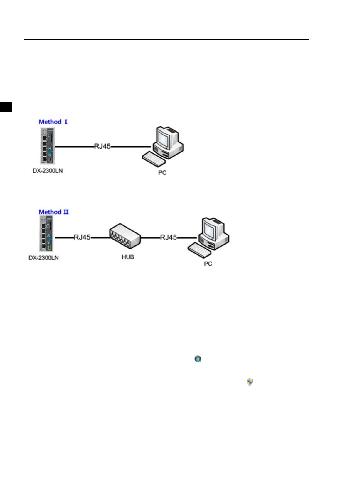
2.1.1 System Connection
First, connect the PC used for configuration with Ethernet interface of the router directly or through the switch/hub.
2.1.2 Default IP Address/Account/Password
The default domain name of router is www.diadevice.com, default IP address is 192.168.1.1. The initial account and
password is admin/admin
2.1.3 Local Network Setups
After the connection of the local computer and the router is done, you will need to set the network configruration for your
computer. There are 2 methods for the setting, we prefer you use the first one:
Obtain an IP address automatically by using the router as a DHCP server.
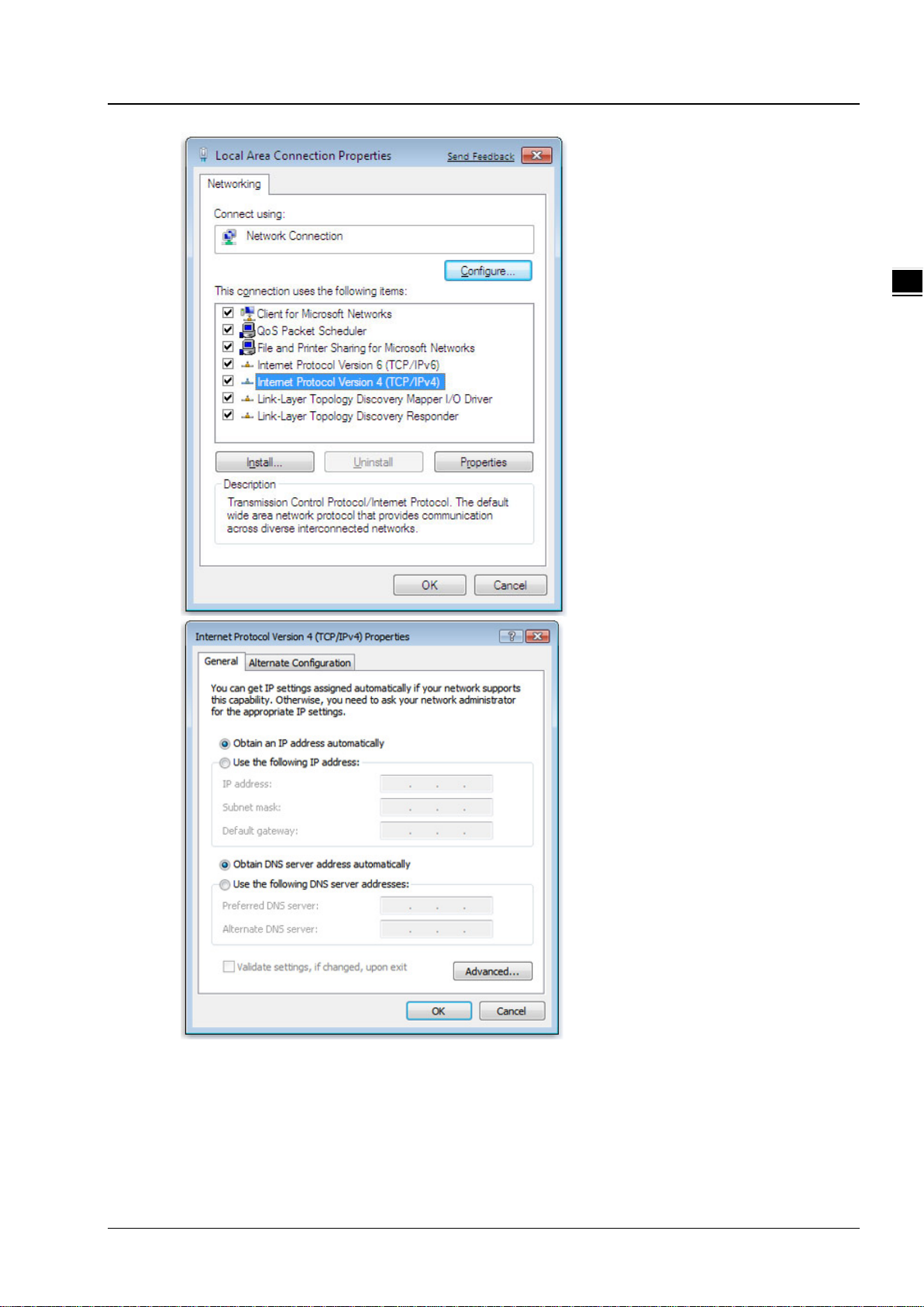
1. Open Network Connections by clicking the Start button , and then clicking Control Panel.
2. Under Network and Sharing Center, click View network connections.
3. Right-click the connection that you want to change, and then click Properties. If you're prompted for
an administrator password or confirmation, type the password or provide confirmation.
4. Click the Networking tab. Under This connection uses the following items, click either Internet Protocol
Version 4 (TCP/IPv4) or Internet Protocol Version 6 (TCP/IPv6), and then click Properties.
5. Click Obtain DNS server address auto mat ic ally an d then cli c k OK to get a DNS server address
automatically using DHCP.
2-2
Page 15
Chapter 2 I ntroductio n to User Inte rface
2_
Set up the IP address manually.
(The IP address of the computer should be in the same network segment as the router’s.)
Since the router’s default IP address is 192.168.1.1 and the subnet mask is 255.255.255.0, the computer’s IP
address can be set between 192.168.1.2 to 192.168.1.254. However, you’ll need to make sure there are no IP
conflicts.
2-3
Page 16

DX-2300 Series Industrial Ethernet C loud Router
2_
Here, we set the address to 192.168.1.10 and the default gateway to 192.168.1.1. For DNS, the usable DNS
address can be selected or the address can also be set to 192.168.1.1.
2.1.4 Logging in
1. Open your Internet Explorer browser and input LAN IP address (Default is 192.168.1.1) or the router’s domain name
(www.diadevice.com) in the search bar and then press Enter.
2. You’ll be prompted with the log-in page. Input the user name and the password (Default is admin/admin) and then
press Enter to log in to the setup page.
2-4
Page 17

Chapter 2 I ntroductio n to User Inte rface
2_
Notice
3. After login, you can see the main selection area on the left hand side and the upper area of the page. The detailed
settings can be seen on the right hand side of the page.
Considerations of the ro uter L A N por t IP will be change after device is activated, after this
if you need login the web still, we prefer you use 192.168.1.1 and use the automatically
obtained IP address and DNS server for the computer
2.2 DIADevice
DIADevice is a tool for quickly configuring network devices. Users simply connect the DX device to the PC through the
network cable. This tool can be used to quickly and easily configure the network setting of the device and complete the
device binding DIACloud cloud account.
The DIADevice software is included in the latest DIACom software package. From the official website or sales staff to
obtain DIACom packag. DX-2300 below as an example on how to configure the device through DIADevice.
The following example uses DX-2300 to show you how to configure your device with DIADevice.
2-5
Page 18

DX-2300 Series Industrial Ethernet C loud Router
2_
2.2.1 Device connection and detection
1. Connect the device to the power supply, and connect the device to the PC using a network cable. Plug the network
cable connected to the Internet into the WAN port of the device
2. Run DIADevice and click ‘Detect’ button
3.
After DIACom detects the device, it will automatically go to the login page, and the user needs to enter login
password on the login page.
2-6
Page 19

Chapter 2 I ntroductio n to User Inte rface
2_
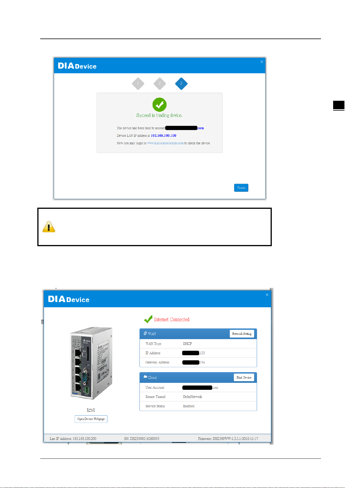
4. After passing the authenticatio n, the device information page is displayed, including the basic device information
(Device Name, S / N, firmware, LAN IP address), network status, WAN information, and cloud service information
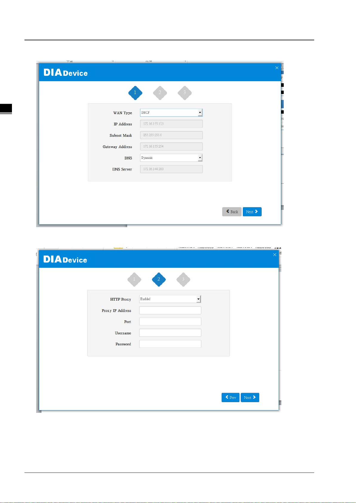
2.2.2 Network Setting
This feature allows you to quickly configure your network in three steps.
1. Click “Network Setting”
2-7
Page 20
DX-2300 Series Industrial Ethernet C loud Router
2_
2. The default is DHCP. If you can not connect to the Internet using auto-setup, please use manual settings.
3. Please confirm the network en v ironme nt and then decide whether to e nabl e HTTP Proxy. If you need to set up HTTP
PROXY, contact your IT staff.
2-8
Page 21

Chapter 2 I ntroductio n to User Inte rface
2_
4. After the device successfully connected to the Internet, the connection was successful.
2.2.3 Bind Device
This feature allows you to quickly bind your device to the DIAcloud in three steps.
1. Click “Bind Device”
2-9
Page 22

DX-2300 Series Industrial Ethernet C loud Router
2_
2. Enter the DIAcloud account number and password, and click Next.
3. After binding configuration is configured, click “Bind” to bind.
2-10
Page 23
Chapter 2 I ntroductio n to User Inte rface
2_
Notice
4. If your device is successfully bound to the cloud, the following screen will appear
If the device has been bound to the cloud account, you need to switch to another cloud
account binding, you only need to repeat 1-3 steps and then enter the new cloud account
you need to bind
2.2.4 Open Device Webpage
. Click open device webpage button, the browser will open the device settings page, the user can set the parameters of
RS232 / 485 configuration.
2-11
Page 24

DX-2300 Series Industrial Ethernet C loud Router
2_
2-12
Page 25

3
Chapter 3 Functions
Table of Contents
3.1 Device Inform at ion .................................................................................... 3-3
3.1.1 Network Status ...................................................................................... 3-4
3.1.2 Routing Table ......................................................................................... 3-5
3.1.3 Local Log ............................................................................................... 3-5
3.1.4 Traffic Statistics ..................................................................................... 3-6
3.1.5 Cloud Status .......................................................................................... 3-6
3.1.6 Connected Device ................................................................................... 3-6
3.2 Network ..................................................................................................... 3-7
3.2.1 WAN Configurations ................................................................................ 3-7
3.2.2 LAN Configurations ................................................................................. 3-9
3.2.3 Static Routing Rules .............................................................................. 3-10
3.2.4 Dynamic DNS ....................................................................................... 3-12
3.3 Firewall .................................................................................................... 3-13
3.3.1 Firewall Settings ................................................................................... 3-13
3.3.2 DMZ Settings ....................................................................................... 3-14
3.3.3 Port Forward ........................................................................................ 3-14
3.3.4 Port Trigger ......................................................................................... 3-17
3.3.5 URL Filter ............................................................................................ 3-18
3.3.6 MAC Filter ............................................................................................ 3-19
3.3.7 IP Filter ............................................................................................... 3-20
3.4 System ..................................................................................................... 3-21
3.4.1 User Management ................................................................................ 3-21
3.4.2 Time Zone Configurations ...................................................................... 3-22
3.4.3 RS232 ................................................................................................. 3-22
3.4.4 RS485 ................................................................................................. 3-24
3.4.5 Modbus TCP ......................................................................................... 3-28
3.4.6 Log Settings ........................................................................................ 3-31
3.4.7 Firmware Upgrade ................................................................................ 3-32
3.4.8 Backup & Restore ................................................................................. 3-32
3.4.9 Scheduled Jobs .................................................................................... 3-33
3.4.9.1 Add A New Job .............................................................................. 3-33
3.4.9.2 Export Job List ............................................................................... 3-34
3-1
Page 26

DX-2300 Series Industrial Ethernet Clou d Router
3.4.9.3 Import Job List ...............................................................................3-34
3.4.10 Network Diagnosis .................................................................................3-35
3.4.11 System Reboot .....................................................................................3-36
3.4.12 Event Management ................................................................................3-36
3.4.13 Register Management ............................................................................3-39
3.5 Cloud Service ........................................................................................... 3-40
3.5.1 Cloud Configurations ..............................................................................3-40
3.5.2 Proxy Setting ........................................................................................3-44
3.6 SD Card Quick Configur ation .................................................................... 3-45
3-2
Page 27

Chapter 3 Introduction to Functions
_3
3.1 Device Information
This page shows basic information on the Hardware/Software version and Resource Usage Information.
Hardware Version
Item Description
RTM Version
Release Date
S/N
Software Version
Item Description
RTM Version
Release Date
Current Version
Release to manufacturing version of the router
Hardware release date
Serial number of the router
Release to manufacturing version of the software
Software release date
Version number of the software currently used on the router
3-3
Page 28
DX-2300 Series Industrial Ethernet Cloud Ro uter
_3
Upgrade Date
Upgrade time of the software currently used on the router
Resource Usage Information
Item Description
CPU Usage
Total Memory
Memory Used
Memory Usage
The CPU usage of current router
The total memory on the router
The memory currently used on the router.
The current ratio of the router usage
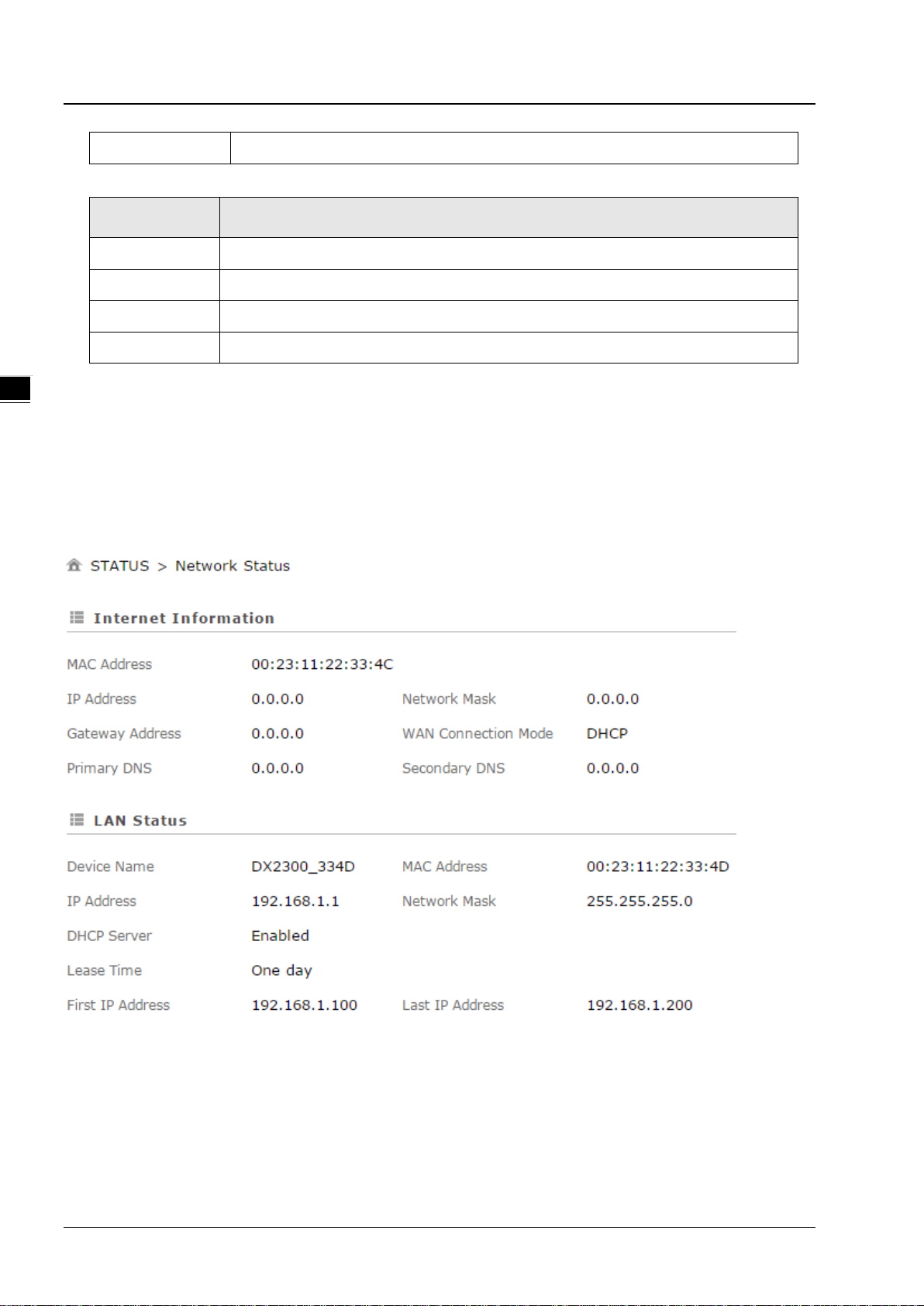
3.1.1 Network Statu s
This page shows basic information on Internet Information and LAN Status.
Internet Information includes the MAC Address, IP Address, Gateway Address, Primary DNS, Network Mask, WAN
Connection Mode, and Secondary DNS.
LAN Status includes the Device Name, IP Address, DHCP Server, MAC Address and Network Mask. When the DHCP
server is enabled, you can see more information, including the address lease time, start address and end address.
3-4
Page 29

Chapter 3 Introduction to Functions
_3
3.1.2 Routing Table
This page shows basic information on the routing table, including the Destination, Gateway, Network Mask, HOPS and
Network Interface.
3.1.3 Local Log
This page shows logs of the router, including the System log, Warning lot and the Debug log. You can use the buttons on
the right hand side to refresh, clear or download the displayed logs.
3-5
Page 30

DX-2300 Series Industrial Ethernet Cloud Ro uter
_3
3.1.4 Traffic Statistics
This page shows network traffic information of the router, including the data sent and received over WAN and LAN. You
can use the buttons on the right hand side to refresh or clear the traffic information.
3.1.5 Cloud Status
This page shows cloud server information of the router, including the Registration Status, Service Status, and Activated
Time.
3.1.6 Connected Device
This page shows information of the devices connected to the router, including the IP Address, Host Name, MAC Address.
3-6
Page 31

Chapter 3 Introduction to Functions
_3
3.2 Network
You can set up networks, including the WAN Configurations, LAN Configurations, Static Routing Rules and Dynamic
DNS.
3.2.1 WAN Configurations
This page is used for setting up the WAN (Wide Area Network), including the WAN Connection Mode, IP Allocation
Method, IP Address, Network Mask, Gateway Address, Packet MTU and DNS.
Description Default
WAN Connection Mode
Your device can connect to the internet via the WAN port with a Dynamic IP
or Static IP.
Static IP: Manually set up the IP address.
Dynamic IP: DHCP (Dynamic Host Configuration Protocol) server on the
network will assign an IP address to the DX router automatically.
IP Allocation Method
The IP Allocation Method is t h e same as the WAN Connection Mode that you
have set. You can apply to different option by modifying the WAN
Connection Mode.
DHCP
DHCP
3-7
Page 32

DX-2300 Series Industrial Ethernet Cloud Ro uter
_3
Description Default
Dynamic: DHCP (Dynamic Host Configuration Protocol) server on the
network will assign an IP address to the DX router automatically.
Manual: Manually set up the IP address (Static).
IP Address
Set up an IP address for your device to connect to the internet via the WAN
port. It’s configurable when the mode is set to Static.
Network Mask
Set up the WAN network mask. It’s configurable when the mode is set to
Static.
Gatew ay A ddress
Set up the gateway address. It’s configurable when the mode is set to Static. 0.0.0.0
MTU
Maximum Transmission Unit is the largest packet that can be transmitted
over packet based networks.
Retrieve DNS Address By
The Retrieve DNS Address Method is the same as the WAN Connection
Mode that you have set. You can apply to different option by modifying the
WAN Connection Mode.
DNS address can be retrieved by DHCP setup or manually set.
0.0.0.0
0.0.0.0
1500
DHCP
Dynamic: DHCP (Dynamic Host Configuration Protocol) server on the
network will assign an DNS address to the DX router automatically.
Manual: Manually set up the IP address (Static).
Primary DNS
Set up the primary DNS. It’s configurable when the mode is set to Static. 0.0.0.0
Secondary DNS
Set up the secondary DNS. It’s configurable when the mode is set to Static. 0.0.0.0
3-8
Page 33

Chapter 3 Introduction to Functions
_3
3.2.2 LAN Configurations
This page is used for setting up the LAN, including the Device Name, IP Address, Network Mask, and DHCP Server.
Description Default
Device Name
Set up a device name for your router. The name shall be composed of
letters, numbers and underline, starting with a letter or number. The
maximum string length is 32 bytes.
IP Address
Set up an IP address for your device. 192.168.1.1
Network Mask
Set up the LAN network mask. 255.255.255.0
DHCP Server
If DX router uses DHCP to assign IP addresses automatically on your
network. You can specify the IP address range and lease t ime for the clients
on your network. Once the DX router have bound the DIACloud and enabled
the DIACloud DHCP the DHCP in DX router will be disabled automatically.
DX2300 + “_” +
“the last four
digits of Mac
address”
Enable
Address Lease Time
To set up the address lease time so that a client doesn't hold an IP address
One day
3-9
Page 34

DX-2300 Series Industrial Ethernet Cloud Ro uter
_3
Description Default
indefinitely. It allows for a mechanism to gracefully reuse DHCP addresses.
Options here are 1 to 3 days.
First IP Address
To increase the number of addresses available to clients, you can change
the Start Address.
Last IP Address
To increase the number of addresses available to clients, you can change
the End Address.
STP
STP is a network protocol that builds a logical loop-free topology for Ethernet
networks. The basic function of STP is to prevent bridge loops and
the broadcast radiation that results from them. If this STP is enabled, the
traffic usage will increase about 15Mbit in 24 hours.
192.168.1.100
192.168.1.200
Disable
3.2.3 Static Routing Rules
This page is used for setting up the Static Routing, including the Rule Name, Network Interface, Enabled, Destination IP,
Network Mask, Gateway Address and Metric. Click the “Add A Rule” to add static routing rules.
After clicking the “Add A Rule”, you will see the following page.
3-10
Page 35

Chapter 3 Introduction to Functions
_3
Description
Rule Name
Set up a name for your rule. The name shall be composed of letters,
numbers and underline, starting with a letter or number. The maximum string
length is 32 bytes.
Network Interface
Default
N/A
For a specific network destination address, select the network interface of
the router for sending data package. Options are LAN and WAN.
Enabled
Activate the static routing functionality. Yes
Destination IP
Set up a Destination IP address for your device. N/A
Network Mask
Set up the subnet mask corre s ponding to the destinati on net work segment. If
the final destination of the routing is a single host, please type in
255.255.255.255.
Gateway Address
Set up the next-hop routing addres s. N/A
Metric
Set up the hops. The number of hops that are passed for reaching the
destination address. One hop indicates passing one router passed. The
range is 2~15.
WAN
N/A
2
3-11
Page 36

DX-2300 Series Industrial Ethernet Cloud Ro uter
_3
3.2.4 Dynamic DNS
This page is used for setting up the Dynamic DNS Settings, including the Dynamic DNS, Service Provider, Domain User
Name, Password, and the Refreshing Interval.
Description Default
Dynamic DNS
Dynamic Host Configuration Protocol allows you to obtain an IP address
automatically from your router. You can enable or disable this functionality.
Service Provider
Select the dynamic domain service provider. www.DynDns.org
Domain
The domain applied for to the corresponding dynamic domain service
provider.
User Name
The name of the user regis tered at t he corre spondi ng dyna mic do main service
provider.
Password
The corresponding password to the registered user. N/A
Disable
N/A
N/A
Refreshing Interval
Set up the time for the router to update its public network IP from the
dynamic domain service provider. The value range is 120~86400 sec.
3-12
86400
Page 37

Chapter 3 Introduction to Functions
_3
3.3 Firewall
You can set up firewall configurations, including the Firewall Settings, D MZ Settings, Port Forward, Port Trigger, URL
Filter, MAC Filter, and IP Filter.
3.3.1 Firewall Settings
This page is used for setting up the basic firewall settings, including the SPI firewall switch, W AN Ping response, LAN
SSH function and WAN SSH.
Description Default
Firewall
The SPI Firewall keeps track of the state of network connections travelling
across it, protecting your Internet connection against Internet threats
and Denial of Service (DoS).
WAN Ping
It creates a filter that your router not to respond to Ping command and
prevents other users o n t h e i nt er net fr om pi ngi ng y our pc and gaining your IP
address.
LAN SSH
Set up whether to allow LAN end to connect with the router via SSH. Enable
WAN SSH
Set up whether to allow WAN end to connect with the router via SSH.
Enable
Not responded
Disable
3-13
Page 38

DX-2300 Series Industrial Ethernet Cloud Ro uter
_3
3.3.2 DMZ Settings
This page is used for setting up the DMZ server.
Description Default
DMZ Server
Demilitarized zone (DMZ) is a special segment of the local network reserved
for servers accessible from the Internet, adding an additional layer of
security.
Disable
DMZ Host IP Address
Set up the IP address for the DMZ host. N/A
3.3.3 Port Forward
This page is used for setting up the port forward, including configuring the Network Services, Service Name, Protocol,
Public Port, Server Port, and Server IP Address.
1. Click the “Add A Portforward Rule” to add port forwarding entries to the router.
2. After clicking the “Add A Portforward Rule”, you will see the following page.
3-14
Page 39

Chapter 3 Introduction to Functions
_3
Description Default
Network Services
Select the common network services. Refer to the following common service list for
optional values.
Service Name
Set up the service name for port forwarding. The name is composed of letters,
numbers and underline, starting w ith a letter or number. The maximum string length
is 32 bytes.
Protocol
Set up the protocol type for port forwarding.
Public Port
Set up the public port for port forwarding. The port range is 1~65534. A Public port
should be less than or equal to the server port.
Server Port
Set up the server port for port forwarding. The port range is 1~65534. A server port
should be greater than or equal to the public port.
When the public port is set to a Single Port, t he server port ca n only be set to a Singl e
Port. When the public port is set to a Port Range, the server port can be set to a
Single Port or a Port Range. And when the public port is set to a single port, all the
port will be forwarded to ONE single port.
Examples of different port forwarding settings:
1:1
Customized
N/A
TCP/UDP
Single Port
Single Port
3-15
Page 40

DX-2300 Series Industrial Ethernet Cloud Ro uter
_3
Description Default
N:1
N:N
Server IP Address
Set up the server IP address that applies to the port mapping rule.
Common Service List for Port Forwarding
Service name
Customized
FTP
HTTP
ICUII
IP_PHONE
Protocol Starting Port Ending Port
TCP, UDP, TCP/UDP 1~65534 1~65534
TCP 20 21
TCP 80 80
TCP 23566 23566
TCP 6670 6670
192.168.1.*
NetMeeting
News
PPTP
Telnet
QuakeII/III
Real-Audio
TCP 1720 1720
TCP 119 119
TCP/UDP 1723 1723
TCP 23 23
TCP/UDP 27960 27960
TCP 6970 7170
3-16
Page 41

Chapter 3 Introduction to Functions
_3
3.3.4 Port Trigger
This page is used for setting up the port trigger, including configuring the Service Name, Service User, Service Type,
Trigger Port, Protocol Role, Begin Port, End Port, and Status.
Port triggering is port forwarding with an on/off switch for the ports that have been forwarded. Have data flown out of a
trigger port or not by enabling or disabling this functionality. Set up the time for the Port Trigger Timeout and click
“Save” to save the setting.
1. Click the “Add A Trigger Rule” to add port trigger entries to the router.
2. After clicking the “Add A Trigger Rule”, you will see the following page.
Description Default
Service Name
Set up the service name for port triggering. The name is composed of letters,
numbers and underline, starting w ith a letter or number. The maximum string
length is 32 bytes.
Service User
Select the service user to apply the port triggering rule. Any Address
N/A
3-17
Page 42

DX-2300 Series Industrial Ethernet Cloud Ro uter
_3
Set up the protocol type for the inbound connection.
TCP/UDP
Manually input the URL address that you’d like to block, for example
Description Default
Service Type
Set up the protocol type for port triggering.
Triggering Port
Set up the triggering port. The por t range is 1~65 534.
Inbound Connection
Protocol Role
Begin port
Set up the starting port for the inbound connec tion. The port range is 1~65534.
End Port
Set up the ending port for the inbound connection. The port range is 1~65534.
Status
Enable/disable the port triggering functionality.
TCP
N/A
N/A
N/A
Disabled
3.3.5 URL Filter
This page is used for setting up the URL Filter, including configuring the URL Address, LAN IP Address and Status.
URL Filter is used to block particular website from the local network. Select Enable/Disable to activate/deactivate this
functionality. Click the “Add An URL Address” to block the URL.
After clicking the “Add An URL Address”, you will see the following page.
Description Default
URL Address
N/A
3-18
Page 43

_3
www.baidu.com.
LAN IP Address
Chapter 3 Introduction to Functions
Description Default
Set up the LAN IP address that you’d like to block. Options are “Any Address”,
“Single Address” and “Address Range”.
Status
Enable/disable the URL Filter functionality.
Any Address
Enabled
3.3.6 MAC Filter
This page is used for setting up the MAC Filter, including configuring the MAC Address, Device Name and Status.
MAC Filter is used to block particular MAC address from the local network. Select Enable/Disable to activate/deactivate
this functionality. Click the “Add A MAC Address” to block the MAC Address.
After clicking the “Add A MAC Address”, you will see the following page.
Description Default
MAC Address
Manually input the MAC address that you’d like to block. N/A
Device Name
Set up the device name corresponding to the set MAC address. N/A
Status
Enable/disable the M AC Filter function ality.
Enabled
3-19
Page 44

DX-2300 Series Industrial Ethernet Cloud Ro uter
_3
3.3.7 IP Filter
This page is used for setting up the IP Filter, including configuring the Source IP, Source Port, Destination IP, Destination
Port, Protocol and Status.
IP Filter is used to block particular IP address from the local network. Select Enable/Disable to activate/deactivate this
functionality. Click the “Add An IP Address” to block the IP Address.
After clicking the “Add An IP Address”, you will see the following page.
Description Default
Source IP
Set up the source IP. Any Address
Source Port
Set up the source port where the datagram came from. Any port
Destination IP
Set up the destination IP. Any Address
Destination Port
Set up the destination port where the datagram is going to. Any port
Protocol
Set up the protocol type for the IP Filter. TCP/UDP
Status
3-20
Page 45

Chapter 3 Introduction to Functions
_3
Description Default
Enable/disable the URL Filter functionality.
Enabled
3.4 System
You can set up the system configurations, including the User Management, Time Zone Configurations, RS232, RS485,
Modbus TCP, Log Settings, Firmware Upgrade, Backup & Restore, Scheduled Jobs, Network Diagnosis, System Reboot,
Event Management, and Register Management.
3.4.1 User Management
You can change the administrator password here. The password must be a combination of 5 to 12 characters, numbers
and/or underline symbols.
Description Default
Old Password
Input the original password. admin
New Password
Input the new password you’d like to use. The password length should be 5-12
digits and is composed of lowercase letters, uppercase letters (case sensitive),
numerals 0-9 and underline.
Confirm Password
Again input the password you’d like to use to double confirm there is no typo. A/A
N/A
3-21
Page 46

DX-2300 Series Industrial Ethernet Cloud Ro uter
_3
3.4.2 Time Zone Configurations
You can change the current time of the device. Use the dropdown list to select the correct time zone for your device.
Description Default
The current time of device
Here shows the current time of your device. N/A
Time Zone Setting
Select the operating time zone of your device: GMT-12:00 - GMT+13:00. N/A
3.4.3 RS232
RS232 (Recommended Standard - 232) is a telecommunication standard for binary serial communications between
devices. You can set up the configurations for RS232, including Baud Rate, Data Bits, Stop Bits, Parity Bits and Flow
Control.
3-22
Page 47

Chapter 3 Introduction to Functions
_3
Description Default
Working Mode
Select the working mode for the current active serial port.
Transparent mode: This mode is suitable for uploading and downloading
data remotely via the serial port.
Slave mode: This mode is suitable for the PLC to perform the read/ write
tasks on the open register of the DX-2300LN-WW.
Close: Disable this functionality.
Baud Rate
Set up the baud rate for the serial port. Options are
2400, 4800, 9600, 19200, 38400, 57600 and
115200.
Data Bits
Parameters of COM
Set up the data bits for the serial port.
Transparent mode: 7, 8
Slave mode: 8
Close
9600
8
Stop Bits
Set up the stop bits for the serial port. Options are
1 and 2.
1
3-23
Page 48

DX-2300 Series Industrial Ethernet Cloud Ro uter
_3
Description Default
Parity Bits
Slave Mode
Set up the parity bits for th e s e rial p or t. O pti ons ar e
None, Odd and Even.
Flow Control
Set up the flow control. Options are None, XON,
XOFF, RTS, and CTS.
MODBUS ID
Set up the ModBus ID. The value is between 1 and
247.
MODBUS Mode
Set up the communication mode for the device.
Device support ModBus RTU and ModBus ASCII.
ModBus Timeout
Set up the timeout timer from 200ms to 3000ms. If
the set value is out of range, it will be automatically
changed to its maximum or minimum value.
None
None
1
ModBus RTU
200ms
3.4.4 RS485
RS485 (Recommended Standard - 485) is a telecommunication standard for binary serial communications between
devices. You can set up the configurations for RS485, including Baud Rate, Data Bits, Stop Bits, Parity Bits, and many
more.
3-24
Page 49

Chapter 3 Introduction to Functions
_3
3-25
Page 50

DX-2300 Series Industrial Ethernet Cloud Ro uter
_3
Read-only: The device regular read data from
Description Default
Working Mode
Select the working mode for the current active serial port.
Transparent mode: This mode is suitable for uploading and downloading
data remotely via the serial port.
Slave mode: This mode is suitable for the PLC to perform the read/ write
tasks on the open register of the DX-2300LN-WW.
Master mode: T his mode is suit able for th e DX -2300LN-WW to perform the
read/write tasks on the open register of the PLC.
Close: Disable this functionality.
Baud Rate
Set up the baud rate for the serial port. Options are
2400, 4800, 9600, 19200, 38400, 57600 and
115200.
Close
9600
Parameters of COM
Data Bits
Set up the data bits for the serial port.
Transparent mode: 7, 8
Modbus RTU: 8
Stop Bits
Set up the stop bits for the serial port. Options are 1
and 2.
Modbus ID
Set up the Modbus ID. The value is between 1 and 247. 1
Modbus Mode
Set up the communication mode for the device. Device support ModBus RTU
and ModBus ASCII.
Modbus Timeout
Set up the timeout timer from 200ms to 5000ms. If the set value is out of range,
it will be automatically chang e d to its max imum or minimu m v alue.
Parity Bits
Set up the parity bits for the serial port. Options are
None, Odd and Even.
None
ModBus RTU
200ms
8
1
Scan Interval
Set up the time for scan interval, r a ngin g from 20ms
Master Mode
3-26
to 60000ms.
Read/Write
Set up the access permissions for the mapped
register address;
30000ms
Read/Write
Page 51

Chapter 3 Introduction to Functions
_3
Description Default
appointed registers in the slave, but will not
update the data to the slave
Write-only: The device update the data to the
slave when the registers values was
changed, but will not read the data from the
slave
Read/write: The device regular read data from
appointed registers in the slave, will update
the data to the slave when the registers
values is changed.
Slave ID
Set up the corresponding slave communication
port. The value is between 1 and 247.
Controller
Device types:
Delta PLC: Use this option for Delta DVP / AH
/ AS series PLCs
Other: Use this option for non-Delta DVP / AH
/ AS series PLCs.
Address Type
Depending on the selected controller type change:
Delta PLC: The address type is "D"
Other: The address type is "W"
Slave Starting Address (decimal)
Set up the slave starting address for read/write the
registers in a PLC.
Delta PLC: Enter the internal D register
number. If you need to r ead / write D0, please
enter 0 here.
Other: Enter the hexadecimal actual addre ss.
For example: Holding Regi ster: 400100, take
0100 (decimal) that is 64 (hex).
P.S. DX supports the Holding Register :
400001~465535 (Decimal)
N/A
Delta DVP
PLC
D
N/A
Device Starting Address (decimal)
Set up the device starting address (decimal, input
range is from $2048 to $4095). Begin with $.
Length (1-123)
Here displays the number of the continuous
address followed by the default mapped
address.
N/A
N/A
3-27
Page 52

DX-2300 Series Industrial Ethernet Cloud Ro uter
_3
Description Default
Add Mappings
Click the button to add mappings; the data mapping
can be set to 200.
Edit
Click an item of register mapping forms that can be
edited.
Operation
The added mappings can be deleted here. N/A
N/A
3.4.5 Modbus TCP
This page is used for configuring the Modbus TCP, including Working Mode, Server IP, Server Port, and Response
Timeout.
3-28
Page 53

Chapter 3 Introduction to Functions
_3
The default is OFF. Other options are:
registers in a PLC. Device supports to connect to 4 different Ser v er at mo st.
Set up the IP address of a PLC in the Modbus TCP
Client mode
Client mode
Description Default
Working Mode
Modbus TCP Server (Slave): for applications of a PLC to read/write the
open registers in DX-2300LN-WW. Device supports up to 32 connections
from client.
Modbus TCP Client (Master): for DX-2300LN-WW to read/write the open
Server IP
Server Port
Set up the server port of a PLC in the Modbus TCP
Response Timeout
Modbus TCP Client
Set up the timeout timer from 50ms to 100000ms.
If the set value is out of range, it will be
automatically changed to its maximum or minimum
value. The default is 300ms.
OFF
N/A
502
300
Scan Interval
Set up the time for scan interval, ranging from
20ms to 60000ms; the default is 3000ms.
30000
3-29
Page 54

DX-2300 Series Industrial Ethernet Cloud Ro uter
_3
Description Default
Read/Write
Set up the access permissions for the mapped
register address;
Read-only: The device regu la r read data from
appointed registers in the slave, but will not
update the data to the slave
Write-only: The device update the data to the
slave when the registers values was
changed, but will not read the data from the
slave
Read/write: The device regular read data
from appointed registers in the slave, will
update the data to the slave when the
registers values is changed.
Slave ID
Read/Write
Add Mappings
Set up the corresponding slave communication
port. The value is between 1 and 247.
Controller
Device types:
Delta PLC: Use this option for Delta DVP / AH
/ AS series PLCs
Other: Use this option for non-Delta DVP / AH
/ AS series PLCs.
Address Type
Depending on the selected controller type change:
Delta PLC: The address type is "D"
Other: The address type is "W"
Slave Starting Address
Set up the slave starting address for read/write the
registers in a PLC.
Delta PLC: Enter the internal D register
number. If you need to read / write D0,
please enter 0 here.
Other: Enter the hexadecimal actual address.
For example: Holding Regi ster: 400100, take
0100 (decimal) that is 64 (hex).
P.S. DX supports the Holding Register :
400001~465535 (Decimal)
N/A
Delta DVP PLC
D
N/A
3-30
Device Starting Address
Set up the device starting address (decimal, input
range is from $2048 to $4095). Begin with $.
N/A
Page 55

Chapter 3 Introduction to Functions
_3
to edit.
Description Default
Length (1-123)
Here displays the number of the continuous
address followed by the default mapped address.
Operation
Delete the selected mapped address. N/A
Add Mappings
Click the button to add mappings; the data
mapping can be set to 200.
Edit
Click to select the records from the ma ppe d addre s s
Operation
The added mappings can be deleted here.
N/A
N/A
N/A
N/A
3.4.6 Log Settings
This page is used for configuring the log settings, including Log to Console, Remote Log Service, Remote Log Server
Address, and Port of Remote Log Server.
Description Default
Log to Console
Set up the log to the console port. No
Remote Log Service
Enable/disable the remote log service. Disable
Port of Remote Log Server
Set up the remote log server port, ranging from 1 to 65534. 514
3-31
Page 56

DX-2300 Series Industrial Ethernet Cloud Ro uter
_3
Notice
Remote log service is used for qualified engineers to check the device remotely when
errors occurred. With this serv i ce, there is no need to log in to the device, device l ogs can
be exported to the remote log server. The server should support the syslog protocol.
When this functionality is enabled, it will take up some resources. Do not enable this
functionality disabled, unless it's necessary.
3.4.7 Firmware Upgrade
This page is used for upgrading the system.
Description Default
Select Firmware
Click “Browse” to select the new firmware file. N/A
Upgrade
Click “Upgrade” to upgrade firmware. The device will reboot after the upgrade
is done.
3.4.8 Backup & Restore
This page is used for backing up and restoring the configurations.
N/A
3-32
Page 57

Chapter 3 Introduction to Functions
_3
numbers and underline, starting with a letter or number. The maximum string
Description Default
Backup
Click “Backup” to save the device configurations on your computer. N/A
Restore
Click “Browse” to select the backup file and then click “Restore” to restore the
configurations. The devi ce con figurat ion will b e restor ed to th e prev ious v ersion
and the device will reboot after the restoring is done.
Restore To Factory Default
N/A
Click “Restore To Factory Default” to reset the configurations to the factory
defaults. The device will reboot after the reset is done.
N/A
3.4.9 Scheduled Jobs
This page is used for scheduling job configurations, including ADD A New Job, Export Job List, and Import Job List.
3.4.9.1 Add A New Job
Click “Add A New Job”, and then you will see the following page. Follow the instruction to add a new scheduled job.
Description Default
Job Name
Set up a name for your scheduled job. The name shall be composed of letters,
N/A
3-33
Page 58

DX-2300 Series Industrial Ethernet Cloud Ro uter
_3
Description Default
length is 32 bytes.
Enable
Select “Enable” to activate this functionality. Enable
Recurring Job
The scheduled job can be done Once, Every day, Ev ery week, or Every month.
And the specific time can be further defined.
Date
Select a specific date to perform the scheduled job. 2015.01.01
Job Type
Select one of the job type for the scheduled job.
Restart device
Enable DIACloud Service
Once
01:00
Restart device
Disable DIACloud Service
3.4.9.2 Export Job List
Click “Export Job List” to export the scheduled jobs for future usage.
3.4.9.3 Import Job List
Click “Chose file” to select the scheduled jobs file you have saved and then click “Import Job List” to import the
scheduled jobs you have set before.
3-34
Page 59

Chapter 3 Introduction to Functions
_3
3.4.10 Network Diagnosis
This page is used for diagnosing the network status; methods are Ping Test and Route Trace.
Description Default
Diagnosing Method
Select the Diagnosing Method; options are Ping Test and Route
Trace.
Host Name/IP Address
Setup the target domain or the IP Address. Options are
www.google.com, www.yahoo.com, www.MSN.com,
www.amazon.com, www.wikipedia.org, www.facebook.com,
www.diacloudsolutions.com and others. When you choose other s,
you can input the domain/IP manual.
Start
Click “Start” to start the network diagnosing. While running the
network diagnosing, the settings cannot be changed.
Stop
Click “Stop” to stop the network diagnosing. After stopping the
network diagnosing, the settings can be changed.
Ping Test
www.diacloudsolutions.com
N/A
3-35
Page 60

DX-2300 Series Industrial Ethernet Cloud Ro uter
_3
3.4.11 System Re boot
This page is used for manually rebooting the system. Click “Restart Device” and the system will reboot.
3.4.12 Event Management
This page is used for setting up 2 types of events, Communication Verification and Alarm Event.
Communication Verification: when the slave (such as PLC) is connected with a router via MODBUS TCP or
MODBUS RTU, the router checks whether the tunnel is a reliable connection-critical loc k or not.
Communication verification expression between PLC and the router can be set here. The expression is the numeri c
expression in C, complying with the standard C programming syntax. The expression can be a single variable, a
constant, or a single variable equation. The name of the variable is limited to “A", and the expression should be
something like this (A+100)*45.
The operators that the expression supports are as below:
Operators Types Examples Description
+ Arithmetic operator A+100 Addition
- Arithmetic operator A-100 Subtraction
* Arithmetic operator A*100 Multiplication
/ Arithmetic operator A/100 Division
& Logic operator A&A+100 Logic AND
| Logic operator A|A+100 Logic OR
3-36
Page 61

Chapter 3 Introduction to Functions
_3
() Bracket operator (A+100)*45 Change operation order
^ XOR operation A^100 XOR operation
Alarm Event: Click “Add” to set a new alar m event, i nput the Alarm Na me, Des criptio n, Ala rm C riter ia, Even t Int erval,
Repeat Times, Alarm Content and Target Receiver. Click “Details” to modify the existing alarm. Click “Delete” to
delete the existing alarm. Click “Copy” to duplicate the alarm.
After clicking “Add”, the following page will show up.
3-37
Page 62

DX-2300 Series Industrial Ethernet Cloud Ro uter
_3
Notice
{} is a special system symbol, which is used to reference system variables or system
Description Default
Alarm Name
Input an alarm name. The name shall be composed of numbers, English
letters, uppercase and lowercase. The maximum string length is 32 bytes.
Alarm Description
The alarm description shall be composed of numbers, English letters,
uppercase and lowercase. The maximum string length is 50 bytes.
Alarm Criteria
The format of alarm variable is {$number 0-4095}, the alar m criter ia can be a
single alarm variable, or a formula of one or several alarm criteria. For
example, the formula can be: {$2003}+{$2004}*100/2-1.
Event Interval
The time interval of alarm sending
Repeat Times
The repeated times of alarm sending
Alarm Content
Set up the information shown on the alarm contents. The content of the alarm
will be sent to the target w hen alarm criteria are met. T he i nfo r mati on or der c a n
be self-defined.
Time: the time when the alarm occurred
Date: the date when the alarm occurred
Name: the name of the occurred alarm
Description: the description of the occurred alarm
For example: Register $2048 represents electrical voltage, the value of
register $2048 is 10, and the alarm content is set as: {Date} {Time} Voltage =
{$2048}, then the query content received by users will be: 2016/06/01
10:00:00(currently time) Voltage = 10. The maximum content length is 95
characters.
N/A
N/A
N/A
0
0
N/A
Target Receiver
Set up the recipient. User can maintain the list by 【Control List Of Event
Management】in Privilege Management function. System only response the
query from receiver list.
registers, like ${Time}, ${Date} or ${Number 0 - 4095}. Please use it with caution.
3-38
N/A
Page 63

Chapter 3 Introduction to Functions
_3
Notice
3.4.13 Register Management
This page is used for setting up the rules of register data upload to Cloud. Click “Add” to set a new rule. Click ”Edit” to
modify the existing rule. Click “Delete” to delete the existing rule.
The address segment 2048~4095 can be self-defined. The Start address, Length, Uploaded to Cloud or not and keep
history or not can be set up.
After clicking “Add”, the following page will show up.
Description Default
Register Start Address
This rule will effect from which register address. The allowable range is
2048~4095. Start with $.
Length
How many register will be effect by this rule. Input range: 1-2048. N/A
Uploaded To Cloud
Whether to upload the variable information into Cloud. Yes
Keep History Data
This function will keep or overwrite the history data when the register values
are uploaded to Cloud.
Yes: The existed register values in the c lou d WON’T be overwritten by the
new uploaded register values.
No: The existed register values in the cloud CAN be overwritten by the
new uploaded register values.
When the values in the register changes, the results will be uploaded to cloud.
N/A
No
3-39
Page 64

DX-2300 Series Industrial Ethernet Cloud Ro uter
_3
3.5 Cloud Service
3.5.1 Cloud Configurations
In this page, user ca n assign the cloud ac cou nt which will be used to connect to DIA Clo ud by device. Input the user name,
the password and click “Verify”. Refer to Chapter 4 for DIACloud account registration.
1. Login with your DIACloud account then click the “Verify” button to authenticate with DIACloud server.
2. After authentication successfully, the cloud configurations will show up then the user can modify the secure tunnel
and device name.
3. The user also can set IP address manually.
4. Click the "Bind" button, the DX router w ill bind with DIACloud server and establishe a secure tunnel between the
3-40
Page 65

Chapter 3 Introduction to Functions
_3
DIACloud server and the DX router. Meanwhile a new IP will assign to DX router from DIACloud server (assign from
the cloud DHCP server or a user specified).
5. Your browser will access to the D X router with new IP address automatically if DIACloud a cco unt binds with
DIACloud server successfully. Please make sure a PC and DX router are in the same subnet; otherwise PC will not
be able to access to the DX router.
6. If the network is in the poor condition, The binding proccess could be successfully but the Service Status is shown
“Disable”.
7. In this s itu atio n, the browser will ac ces s to 192.168.1.1 and the service status will be “Disable”. You can re-enable the
service status to rebuild the secure tunnel again in cloud configurations.
3-41
Page 66

DX-2300 Series Industrial Ethernet Cloud Ro uter
_3
8. When the service status is shown “Enable”, that means the DIACloud service is actived on DX-2300LN-WW. The
user also can get the related information in cloud platform.
9. Click the “Unbind” button, DX-2300LN-WW will remove the registered account in DIACloud.
Description Default
User Name
Set up the name for the DIACloud account. N/A
Password
Set up the password for the account. N/A
Verify
Check if the username and the password are matched. N/A
Secure Tunnel
Select the device under the account to join in a certain secure tunnel network
group. For secure tunnel related settings, go to
http://www.DIACloudSolutions.com/
3-42
Default
Page 67

Chapter 3 Introduction to Functions
_3
Notice
and register for a
Description Default
Device Name
Set up the name for the device N/A
Secure Tunnel DHCP
When secure tunneling DHCP server is available, and the IP address is
allocated by the DHCP server in secure tunnel network, the IP address of this
de vice can be found in the cloud portal.
Get IP From Cloud
When selecting “Yes”, IP address can be obtained by the cloud. When
selecting “No”, the IP address can be manually set. Page will display IP range
for user reference.
Cloud IP Rang
Display the Cloud IP Range. The Cloud IP Range is depended on the secure
tunnel setting. For the secure tunnel setting, please refer to 5.2.5 Tunnel
Network.
N/A
Yes
N/A
Cloud Netmask
Display the Cloud Netmask. The Cloud Netmask is depended on the secure
tunnel setting. For the secure tunnel setting, please refer to 5.2.5 Tunnel
Network.
Device IP
User can assign a IP address for this device, the IP should be in the same
subnet with Cloud IP.
Users can log in to http://www.DIACloudSolutions.com/
DIACloud account.
In rare case, you can’t ac cess the w eb becau se the computer did not refresh the IP
after the activation, please re-plug the cable to resolve the issue.
N/A
N/A
3-43
Page 68

DX-2300 Series Industrial Ethernet Cloud Ro uter
_3
3.5.2 Proxy Settin g
If the user’s networking environment requires outbound network connections to go through a HTTP or HTTPS proxy.
Description Default
HTTP Proxy
Enable or disable the http proxy Disable
Proxy Addr
Set up the domain/IP of the proxy server N/A
Proxy Port
Set up the port of the proxy server N/A
Proxy Username
Set up the user name to login the proxy server N/A
Proxy Password
Set up the password to login the proxy server. N/A
Save and Test
Save the configuration and test to connect to the DIACloud. N/A
3-44
Page 69

Chapter 3 Introduction to Functions
_3
3.6 SD Card Quick Configuration
DX-2300LN provides the multiple configurations via SD Card quickly.
Upgrade the device firmware
Import the device configuration
Active the device with the DIACloud account.
The SD Card quick configurations will triggers by the following file is created in the SD card after the DX-2300LN reboots:
The upgrade-package file ’DX2300_UpgradeImage_NorFlash_xxxx_xxxx.bin’
The device configuration files ‘backup.cfg’. (Please refer 3.4.8 Backup & Restore)
The cloud configuration file ‘Provision.bin’ (Please refer to the following steps).
1. Go to the DIACloud platform (DIACloudSolutions.com).
2. Log in the DIACloud w ebpage and cli ck “SECURE TUNNELS”
3. Click to select the Network which you’d like to use and then click the
4. Click the
to download the generated Provision.bin to the local computer.
to see and check the details.
5. Copy Provision.bin file to SD card.
Power off the device and then insert the SD card into the devi ce (SD card slot b elow the SIM card slot, on the right side of
the device). Turn on the device and it will automatically bind. Check the SD card status indicator to see if the binding is
successful.
The following beep codes are for SD Card Quick Configurations, its definition that the various combinations of the
configuration file exist on SD card. (× – fail, √ - success or not this operation)
Beep Code Upgrade.bin backup.cfg Provision.bin
1 long
1 long, 1 short
× √ √
√ × √
3-45
Page 70

DX-2300 Series Industrial Ethernet Cloud Ro uter
_3
Notice
SD Card Quick
1 long, 2 short
1 long, 3 short
1 long, 4 short
1 long, 5 short
1 long, 6 short
None
Name rule for BIN file: Provision.bin
Please do not change the file name of firmware upgrade-package.
Please do not create the two different upgrade-package file in SD Card. In order to
At least a 10-minute interval of separation between the two
× × √
√ √ ×
× √ ×
√ × ×
× × ×
√ √ √
avoid the upgrading process fails.
Configuration
3-46
Page 71

4
Chapter 4 DIACom
Table of Contents
4.1 Introduction to DIACom ............................................................................. 4-2
4.1.1 Select a Suitable Firmware Version ........................................................... 4-2
4.1.2 DIACom Installation ................................................................................ 4-3
4.1.3 DIACloud Account Registration ................................................................. 4-3
4.1.4 Bind DIACloud Account............................................................................ 4-5
4.2 DIACom Operation ..................................................................................... 4-6
4.2.1 Setup a Secure Tunnel ............................................................................ 4-6
4.2.2 Create a Virtual Serial-port ...................................................................... 4-9
4.2.3 Remote Control and Monitoring via DIACom ............................................. 4-10
4-1
Page 72

DX-2300 Series Industrial Ethernet Clo ud Router
_4
Notice
Device Model
Firmware Version
DX-2100
V1.3.3.0 or above
DX-2300
V1.3.3.0 or above
Notice
If the device firmware is lower than 1.3.3.0, please use DIACom 1.2.8.0 or
4.1 Introduction to DIACom
DIACom allows you to create a secure tunnel between your PC and router, making it possible for
your PC to communicate remotely with the devices connected to the router. Thus engineers can
control, monitor, operate, program and diagnose the device remotely whenever there is internet
connectivity.
DIACloud provides you with cl oud serv ice s, including the connected device
management, secure tunnel network creation, data upload/download, and
directional transmission.
If you need to configure or monitor your controller, you will need to install
programmable logic controller software, for example WPLSoft/ISPSoft for Delta
PLC.
4.1.1 Select a Suitable Firmware Version
Find a suitable DIACom firmware version according to the following table below for your router.
Corresponding Table:
lower.
4-2
Page 73

Chapter 4 Introduction to DIACom
4_
Notice
Notice
English.
4.1.2 DIACom Installation
Obtain the DIACom firmware package from the official website or fro m our sales representative.
Administrator privileges are required to run and install the package. Uninstall older versions of
DIACom before downloading new DIACom firmware package.
DIACom supports Windows XP, W indows 7 (32-bit and 64-bit) and Windows 8
(32-bit and 64-bit).
4.1.3 DIACloud Account Registration
1. Before registration, you should have a valid email account. (DIACloud uses your email
address as your account.)
2. Open the DIACloud web page (http://www.DIACloudSolutions.com). The system w ill re dir e ct
you to the registration page:
*Click at the upper right corner to change the interface language to
3. Input your email address, password and other relevant information on the registration page.
Select “I Agree” and click “CREATE AN ACCOUNT”.
4-3
Page 74

DX-2300 Series Industrial Ethernet Clo ud Router
_4
4. After clicking “CREATE AN ACCOUNT”, a congratulation page will be prompted and an
activation email will be sent to the email address you have used as your DIACloud account.
5. You will find an activation email sent from no-reply@diacloudsolutions.com
Open the email, click “here” link in the email and complete DIACloud account activation
operation. And you will be redirected to the DIACloud login page. Input your account and
password to log in to the DIACloud.
in y our emai l box.
4-4
Page 75

Chapter 4 Introduction to DIACom
4_
Notice
4.1.4 Bind DIACloud Account
Follow the steps blow to bind your DIACloud Account.
1. Local Network Setups: Please refer to Chapter 2.1 to 2.1.3 Web-based GUI Configuration for
more information.
2. Bind DIACloud Account: Please refer to Chapter 3.5 Cloud Service for more information.
Secure Tunnel: Secure tunnel is a virtual network. Users can set up several
groups of secure tunnel for easier device management.
Device Name: the seri al number + “_” + “Mac address” of the device is the device
name by default.
Get IP From Cloud:
When selecting “Yes”: The system will assign an IP address for the device
according to the Secure Tunnel settings and the availability of the IP
addresses. Take note of the assigned IP address, it will be used when
logging to the DIACloud.
When selecting “No”: The IP address can be manually set.
The IP address of the DX-2100 Series and the WAN of your connected PC should be in
different network segments.
4-5
Page 76

DX-2300 Series Industrial Ethernet Clo ud Router
_4
4.2 DIACom Operation
4.2.1 Setup a Secure Tunnel
Make sure there is internet connectivity , before creating a secure tunnel between your local PC
and router via the DIACom. Http Proxy and Port Agent are configurable in DIACom network
setting function, you can set it to avoid the possible limitation.
1. Run DIACom and log in with your router’s cloud account.
2. Click
to go into network setting page if need be.
Http proxy: Please fill in the proxy server address, port, username and password if
the LAN needs to set the proxy to access the Internet. Click “Save” button to enable
the config.
Diagnose: The user can c lick the Diagnostic button to test the current internet settings,
whether to connect to the DIACloud server
4-6
Page 77

Chapter 4 Introduction to DIACom
4_
Notice
DIACom will automatically determine whether the port agent
needs to enable.
Make sure that the external network port 80 and port 443 are
opened and can access any network domains and IP addresses
3. After the login is successful, the sof tware displays the security tunnel page. The se curity
tunnel list is displayed on th e l eft side of the page, and t he n etwork information of the security
tunnel and the device list are displayed on the right. Users can choose to use DHCP or
manually set the cloud IP address
DHCP: Obtain an IP address from Cloud automatically when Cloud DHCP function is
available.
Static: Manually set the IP address, the IP should be in the same subnet with DX
device
4-7
Page 78

DX-2300 Series Industrial Ethernet Clo ud Router
_4
4. After the configuration is complete, click the Create Tunnel button to establish a connection
with the specified tunnel.
5. The following information is displayed: tunnel connection status, local delay to the DIACloud
cloud server, and the IP address used by the local virtual network adapter. The details are as
follows:
6. After successful connection with the cloud, the local computer will be able to use debugging
tools or monitoring software to debug, monitor, and program the remote network interface
devices. In addition, you can remotely configure the router's router page (click the device in
the device list Of the IP address) of the router for remote configuration.
Notice
You can create different groups of secure tunnels, divide different devices into
groups according to their needs, and implement group management devices
To avoid the virtual network card IP network segment and the local computer
network card of the actual network to avoid the same network conflict
After the secure tunnel is successfully conn ect ed, you mu st fi r st disconn ect t he
current connection to select another security tunnel,
4-8
Page 79

Chapter 4 Introduction to DIACom
4_
4.2.2 Create a Virtual Serial-port
To debug a remote serial device, click the icon at the back of the corresponding remote
device to enter the Create Virtual Serial Interface
The latest device firmware (V1.3.3) supports RS-232 and RS-485 at the same time in the
transparent mode, the interfac e as shown below:
Notice
If the device's RS-232 / RS-485 is not operating in Transparent mode, the
corresponding button is grayed out.
DIACom will prompt an error message if the FW version of DX is under V1.3.3.
4-9
Page 80

DX-2300 Series Industrial Ethernet Clo ud Router
_4
When RS-232 or RS-485 works in Transparent mode, click on the [Create Serial
Port] button on RS-485 to create a virtual serial port.
4.2.3 Remote Control and Monitoring via DIACom
4.2.3.1 Via a LAN Port
If your router is connected to remote devices via a LAN port, you can use the
configuring/monitoring software on your local computer to configure and monitor after opening a
virtual tunnel. Some program would require the IP addresses of your remote device. Simply input
the required information in the configuring/monitoring software and then you can configure and
monitor the connected device remotely.
4.2.3.2 Via a RS232/RS485 Port
After opening a virtual tunnel, you will need to follow the setups below before using WPLSoft or
other configuring/monitor ing s oftware on your local computer to configure and monitor the
connected device remotely.
1. Click IP address in the DIACom device list or open a browser and input the IP address of the
router which is connected to your remote device on the search bar and then log in.
2. Go to the System setup page, select th e setup op tion RS 232 or RS485 an d input the required
information to set up. Mak e s ure the parameters are consistent with your remote device.
Working Mode:Tr ansparen t mode
Parameters of COM (Baud Rate, Data Bits, Stop Bits, Parity Bits, Flow Control)
3. Go back to the DIACom and click to create a virtual tunnel. Once the creation is done,
the virtual serial-port number will show up on the same page. Users can use it to configure
and monitor the connected device remotely. Click “Delete” to delete the virtual serial-port.
4-10
Page 81

Chapter 4 Introduction to DIACom
4_
Notice
If the PLC is Siemens S7-200, you can selec t the “PPI” in the DIACom to support PPI
protocol.
4. Open the WPLSoft to che ck if the COM parameters are consistent with the settings on your
router. When these paramet er s are con sistent, y ou can use the WPLSoft t o confi gure/mo nitor
your device remotely.
4-11
Page 82

5
Chapter 5 DIACloud
Table of Contents
5.1 Introduction to DI ACl oud .............................................................................. 5-2
5.1.1 Select a Suitable Firmware Version .............................................................. 5-2
5.2 Instructions for DIACloud .............................................................................. 5-2
5.2.1 Register and Login ..................................................................................... 5-2
5.2.2 Home ....................................................................................................... 5-4
5.2.3 Devices .................................................................................................... 5-6
5.2.4 Alarm ..................................................................................................... 5-15
5.2.5 Secure Tunnels ........................................................................................ 5-16
5.2.6 Sub Users ............................................................................................... 5-18
5.2.7 Logs ....................................................................................................... 5-21
5.2.8 Orders .................................................................................................... 5-21
5.2.9 Profile .................................................................................................... 5-22
5-1
Page 83

DX-2300 Series Industrial Ethernet Clo ud Router
_5
Device Model
Firmware Version
DX-2100
V1.3.0.1 or above
DX-2300
V1.0.0.1 or above
Notice
5.1
DIACloud Web is a web portal of DIACloud cloud platform. Users can check the status of connected industrial device
through DIACloud Web, browse data that has been col le cted, r ece ive warnings, notices and other messages that are sen t
by cloud platform, create and manage sub-account and virtual safety network and check login and interface logging, to
improve the manageability of devices, optimize the device performance and efficiency, save the operation cost and
enhance the service quality.
Introduction to DIACloud
5.1.1
Please confirm that your Firmware version of router meets the requirements in the following table before use:
5.2
5.2.1
1. Open the DIACloud web page (http://www.DIACloudSolutions.com). If you have got an account, input your account
Select a Suitable Firmware Version
and password in the following page to log in; if you have not got an account, click “CREAT AN COUNT” to register.
Then the system will redirect you to the registration page:
Instructions for DIACloud
Register and Login
2. Input your email address, password and other relevant information on the registration page. Select “I Agree” and
click “CREATE AN ACCOUNT”. Pls insure your region information is correct, otherwise it maybe cause problem in
payment when you extend your service.
Click at the upper right corner to change the interface language to English
or Chinese.
5-2
Page 84

CH5 Introduction to IOT DIACloud
_5
3. After clicking “CREATE A N ACCO U NT” , a congratu lation page will be prompted and an a cti v ation em ail will be sent
to the email address you have used as your DIACloud account.
4. You will find an activation email sent from no-reply@DIACloudSolutions.com
click “here” link in the email and complete DIACloud account activation operation. And you will be redirected to the
DIACloud login page. Input your account and password to log in to the DIACloud.
in your email box. Open the email,
5-3
Page 85

DX-2300 Series Industrial Ethernet Clo ud Router
_5
5. Open the DIACloud web page (http://www.DIACloudSolutions.com
registered.
5.2.2 Home
The Home Page will show up after login.
). Log in using your account that you have
5-4
Page 86

CH5 Introduction to IOT DIACloud
_5
Virtual Networks is
Usable
add packeage to shopping cart
Item Description
Menu User can switch to corresponding function through menu on the left.
Devices Total The number of total devices
Devices is Online The number of total online devices
Alarms in 24 Hours The number of alarms in Recently 24 hours
It will show the number of Secure Tunnel groups under the account.
Switching among the Chinese and English
Show the service package you selected, user can
through Devices function and Profile function.
Show the alarm message(s) in latest 7 days
Show the profile or logout
Online payment process as below :
1. After click
2. Click to generate an order. DIACloud provides the follow types of invoices.
, it will show the detail information in shopping cart .
No need For Invoice
Electric Invoice
Paper Invoice
5-5
Page 87

DX-2300 Series Industrial Ethernet Clo ud Router
_5
3. Click , we accept PayPal payments and process credit cards on your order forms.
5.2.3
It will switch to page of device list after clicking “Devices” in navigation bar.
Devices
Item Description
You can filter the device base on you input the key word of the device name.
5-6
Page 88

CH5 Introduction to IOT DIACloud
_5
Filter base on tunnel group, show all devices or only show the devices under user
specified tunnel group.
Show the list of device.The information include device’s name, device’s SN, device’s
Gray represents the devic e is of f-line.
epresents that all device is displayed currently, and you can switch to
line device is displayed currently, and you can switch
Devices List
: It will show relevant position information of device after you click “ ” , which is shown as follows:
type, storage usage, data usage, the time of binding device.
Green represents that the device is on-line
: Represents that on-
Show relevant position information of device.
Refresh pages
Show detail information of the device
: R
on-line device list after clicking this icon.
to list of on-line device after clicking this icon.
It will show the device name and SN of the device after clicking position icon in the map. When there is large number of
device of user, it will switch to corresponding device when user clicks blue arrows at the edge of the map.
: More detail information about device will be shown after clicking under the “Operation” at the
most right side of device list:
1. OVERVIEW: The page will show the basic information of the device and latest alarm message.
5-7
Page 89

DX-2300 Series Industrial Ethernet Clo ud Router
_5
It represents that dev ice is on-l ine i f ba ckg round color is blue, and dev ice is off-line if it
: Close the operation page.
Different buttons are used to switch different pagers.
Basic information is shown in Overview page.
Modbus TCP Client and Closed
Item Description
Operation zone of dev ic e
Page switching
is gray.
: Show device names; it can switch device after clicking the
drop down arrow.
: Realize refresh of device data on operation page.
Operation is divided into 4 pages:
Overview
Registers
Package
More
IP Address: it means the IP that has been bound for device;
Tunnel Network: it means virtual network that has been bound to device;
Boot Time: it means the boot time of dev ice;
Basic information zone
RS232 Mode: work modes of RS232, including transparent transmission mode
and slave station mode;
RS485 Mode: work modes of RS 485, including transparent transmission
mode, slave station mode and master station mode;
5-8
Modbus TCP: work modes of Modbus TCP, including Modbus T C P Serv er ,
Page 90

CH5 Introduction to IOT DIACloud
_5
Red represents failure of sending.
button. DIACloud server will send the corresponding data to the device.
the total amount of register table page.
Show the register name, when you do not make an alias configuration in the register,
the register number is di spl ay e d; an ali as conf iguration in the register w ill b e di spl ay ed
after you configure the alias
also be configured to register.
RSSI: it means signal strength of device which contains 5 bars; the larger the
number of green bars is, the stronger the signal strength is;
Latest Alarms
The latest five Alarm of the current device. “
being sent;
Green represents that the email has been sent successfully
” represents the state that the email is
2. REGISTER: The page will show and manage register value that uploaded from DX production.
Item Description
The filtering function displays a list of keywords that match specific register.
Click and add the corresponding register and register value, then click “SAVE”
“<” Pervious p age,“>” Next page,“1/205” show the current page of regi ster table and
Register Table Show the register table, registers show a maximum of 10 posts per page.
Register Name
Register Value Show the current register value and data transfer time.
You can view the current register of historical data or delete the current register; it can
5-9
Page 91

DX-2300 Series Industrial Ethernet Clo ud Router
_5
P.S. If t his register is not set to remeber history (device configuration page), the menu
does not appear [History] after clicking icon.
The History and Config options will be shown after clicking
\
Item Description
History It represents trend chart of historical data
Delete User can delete the all data of this register
Config User can customize name of register and content returned.
Histo ry : The following figure will be shown after clicking “History”:
5-10
Page 92

CH5 Introduction to IOT DIACloud
_5
a specifi c time
time
User can change time s cope o f histor ical dat a by s liding “ ”.
The user can set t he name of the regi ster to be displa yed in the
"Alias Name"
Item Description
Date Start
Date End
Register Value History Diagram The latest trend chart of value of register;
Time Ax is
Set the Date Stare and query the historical data for
Set the Date End and query the his tori cal data for a specific
Config : The following information will be shown after clicking “Config”
Item Description
Alias Name
5-11
Page 93

DX-2300 Series Industrial Ethernet Clo ud Router
_5
function(val) is used for convert the register value, and the
grammar of function-supported JavaScript is similar.
function(val)
There are two examples for “function (val)”.
Example 1 : If you want to show the wind speed as 10m/s. (Data +unit, such as: speed 10m/s).
1. Input the code: return val+“m/s” in function (val){…} as the following picture.
2. Save the configuration.
Example 2: If you want to convert the register value to the text such as the register value of 1 shows the text as ‘NO’;
register value of 2 shows the text as ‘OFF’
1. Input the code in function (val) {…} as the following picture.
2. Save the configuration.
5-12
Page 94

CH5 Introduction to IOT DIACloud
_5
SERVICES: This page shows the Device Data Usage, Device Storage Usage and Account Storage Usage for users.
Data
Storage
Item Description
Device Data Usage: Show device traffic usage this month and
monthly capacity.
:User can purchase more traffic package for this devic e if
need.
: Show the Data Usage History in past 12 months.
Device Storage Usage: Show device storage usage till now and
total capacity
Account Storage Usage: Show account and device storage usage
till now and total capacity,ac c ount stor a ge will shar e to all dev ice
under this account, device storage only use for its elf.
:User can purchase more storage package for this account
if need.
5-13
Page 95

DX-2300 Series Industrial Ethernet Clo ud Router
_5
Notice
1. After Click the , it will show the traffic package select page. User can add a package to cart or pay it direct.
2. After Click the
Traffic package is tie to d ev ice and c omputed se parately f or each devic e, user can
purchase more for each device
Initial storage package is tie to device, after the device’s storage is spent all, it wil
charge to account storage. User can purchase more for account only. This means
the account storage will share to all devices under this account.
, it will show the Data Usage History in past 12 months.
5-14
Page 96

CH5 Introduction to IOT DIACloud
_5
Delete binding relationship between device and the account. Device
the device by rebinding.
MORE: This page will show the Serial Number, Software Version, Hardware Version, and IMEI for users.
Item Description
Serial Number Serial number of device
Software Version Version information of software
Hardware Version Version information of hardware
IMSI International Mobile Subscriber Identification Number.
5.2.4
Click the Alarm in the left menu. The warning information in the latest 7 days will be shown in this page. The warning
information includes name and serial number of device, content of warning, status of email that is being sent (green“
represents that the email has been sent successfully, and red represents fail.), time of warning and content record of
warning.
Alarm
needs to be un-bund after clicking this button, and user can recover
”
5-15
Page 97

DX-2300 Series Industrial Ethernet Clo ud Router
_5
5.2.5 Secure Tunnels
Secure Tunnel is an important con cept in DIACloud. Its object ive is to r ealiz e virt ual Swit ch a cross Int ernet; when dev ice is
bound to this network, it will be equivalent to adding device with one LAN port; when PC operates DIACom and creat es a
virtual network, PC and the device will be under the same switch at this time. It is shown as follows:
換照片
5-16
Page 98

CH5 Introduction to IOT DIACloud
_5
Search the existed tunnel network
Refresh the tunnel network list
Edit the tunnel network
The detail information of tunnel network:
Users can manager the tunnel network in this page. Interface is shown as follows:
tem Description
Tunnel network List
List all tunnel network under this account
Add a new tunnel network
Item Description
Tunnel Network Information
Network Name: User can enter a name of tunnel network.
DHCP Option: Automat ic IP Address Assignment by DIACloud.
DHCP IP Start: it represents the beginning IP in automatic IP
distribution address pool of DIACloud
DHCP IP End: it represents the ending IP in automatic IP distribution
address pool of DIACloud.
5-17
Page 99

DX-2300 Series Industrial Ethernet Clo ud Router
_5
Note: Detail configuration, please refer to 3.2 SD Card Quick Installation.
Search the sub users.
Refresh the list of sub users.
Modify the access control of the tunnel network.
If the DHCP of thes tunnel network is enabled, click will export
configurations include DIACloud Servier /account /Tunnel networks info to a
file (default file name Provision_vlnname_date_time.bin).
Delete the current tunnel network
Close the current operation window.
Save the configuration of tunnel network
5.2.6
All accounts that are registered through register page of DIACloud (http://www.DIACloudSolutionscom/#/signup) are mai n
accounts. Every main account can create sub-account, and users can realize power separation and grouping
management of device by conducting authorization for virtual network and DIACom by sub-account. Use can conduct
addition and operation for sub-account through the “Sub Users” page.
Sub Users
Item Description
Sub Users List
5-18
: User can modify the access control of the tunnel network.
Show the list of all sub users in main account.
Add a sub user.
Page 100

CH5 Introduction to IOT DIACloud
_5
user to access the Tunnel Network if
Item Description
Login to DIACom: Allow the sub user to access the DIACom if the
Sub Users Information
option is enabled.
Tunnel Network: Allow the sub
the option of Tunnel Network is checked.
Delete a sub user.
Close the current operation window.
: User can add sub users after clicking the “+” in the page, and. The following interface will be shown after
clicking the “+” in the page:
5-19
 Loading...