

Page 1

2016-11-25
Page 2

DVW Series Industrial IEEE 802.11 a/b/g/n
Wireless AP/WDS/Client/Gateway
User Manual
Contents
Chapter 1 Introduction
1.1 Feature ......................................................................................... 1-4
1.1.1 High Performance Network Technology ....................................... 1-4
1.1.2 Industrial Grade Reliability ........................................................ 1-4
1.1.3 Robust Design ......................................................................... 1-4
1.1.4 Front Panel Ports and LEDs ....................................................... 1-5
1.1.5 Below Panel ............................................................................ 1-6
1.2 Antenna Installation ....................................................................... 1-7
1.2.1 Package Checklist .................................................................... 1-7
Chapter 2 User Interface Introduction
2.1 USB Console Configuration .............................................................. 2-2
2.2 Telnet Console Configuration ........................................................... 2-7
2.3 Web Browser Configuration ............................................................. 2-8
Chapter 3 Featured Func tions
3.1 System ......................................................................................... 3-4
3.1.1 System Inform at ion ................................................................. 3-4
3.1.2 System CPU Status .................................................................. 3-4
3.2 Basic Configuration ......................................................................... 3-5
3.2.1 System Information Configuration ............................................. 3-5
3.2.2 Network Configuration ............................................................. 3-5
3.2.3 Time Configuration .................................................................. 3-8
3.2.3.1 Local Time Configuration ...................................................... 3-8
3.2.3.2 NTP Server Configuration...................................................... 3-9
3.3 Seria l Configuration ...................................................................... 3-10
3.3.1 Operation Configuration ......................................................... 3-10
3.3.1.1 MODBUS ASCII/RTU Slave .................................................. 3-10
3.3.1.2 MODBUS ASCII/RTU Master ................................................ 3-12
3.3.1.3 TCP Server Mode ............................................................... 3-15
i
Page 3

3.3.1.4 TCP Client Mode ................................................................ 3-18
3.3.1.5 Virtual COM Mode .............................................................. 3-23
3.3.1.6 UDP Mode ......................................................................... 3-26
3.3.1.7 Pair Connection Mode ......................................................... 3-30
3.3.2 Port Configuration ................................................................. 3-32
3.3.3 MODBUS Cache Table ............................................................ 3-33
3.4 WLAN Manager ............................................................................ 3-36
3.4.1 Operation Mode ..................................................................... 3-36
3.4.1.1 AP Mode ........................................................................... 3-37
3.4.1.2 Client Mode ....................................................................... 3-37
3.4.1.3 Repeater Mode .................................................................. 3-37
3.4.1.4 WDS Master and Slave Mode ............................................... 3-38
3.4.1.5 Regions ............................................................................ 3-38
3.4.2 WLAN ................................................................................... 3-39
3.4.2.1 Basic Wireless Configur ation – AP Mode ................................ 3-39
3.4.2.2 Basic Wireless Configur ation – Client Mode ........................... 3-41
3.4.2.3 Basic Wireless Configur ation – Repeater Mode ....................... 3-42
3.4.2.4 Basic Wireless Configur ation – Master Mode .......................... 3-44
3.4.2.5 Basic Wireless Configur ation – Slave Mode ............................ 3-46
3.4.2.6 Basic Wireless Configur ation – Security Mode ........................ 3-48
3.4.3 Advanced Wi reless Configurati on ............................................. 3-51
3.5 Advanced .................................................................................... 3-53
3.5.1 VLAN Configuration ................................................................ 3-53
3.5.2 Packet Control ....................................................................... 3-54
3.5.2.1 Filter Configuration ............................................................ 3-55
3.5.2.2 MAC Filters ....................................................................... 3-55
3.5.2.3 IP Protocol Filters .............................................................. 3-56
3.5.2.4 TCP/UDP Port Filters .......................................................... 3-57
3.5.3 RSTP Configuration ................................................................ 3-57
3.5.4 SNMP Configuration ............................................................... 3-58
3.5.5 Storm Control ....................................................................... 3-60
3.6 Auto Warning Settings .................................................................. 3-61
3.6.1 SysLog ................................................................................. 3-61
3.6.1.1 Syslog Event Types ............................................................ 3-61
3.6.1.2 Syslog Server Configuration ................................................ 3-63
3.6.2 E-mail Alarm ......................................................................... 3-63
3.6.2.1 E-mail Event Types ............................................................ 3-63
3.6.2.2 E-mail Server Configuration ................................................ 3-64
ii
Page 4

3.6.3 Relay Alarm .......................................................................... 3-65
3.6.3.1 Relay Event Types ............................................................. 3-65
3.6.4 SNMP Trap ............................................................................ 3-66
3.6.4.1 Trap Event Types ............................................................... 3-66
3.6.4.2 SNMP Trap Receiver Settings .............................................. 3-66
3.7 Monitoring Settings ...................................................................... 3-67
3.7.1 Email Alarm T able ................................................................. 3-67
3.7.2 Relay Alarm Table ................................................................. 3-67
3.7.3 Trap Alarm Table ................................................................... 3-68
3.7.4 System Log .......................................................................... 3-68
3.7.5 Network Connection Status ..................................................... 3-69
3.7.6 AP Client List......................................................................... 3-69
3.7.7 DHCP Client List .................................................................... 3-69
3.7.8 Serial Port State .................................................................... 3-70
3.7.9 Serial Port Statistics ............................................................... 3-70
3.7.10 Serial Port Error .................................................................... 3-70
3.7.11 Serial Port Log ...................................................................... 3-70
3.8 Management Access ..................................................................... 3-71
3.8.1 SSH Configuration ................................................................. 3-71
3.8.2 Telnet Configuration .............................................................. 3-71
3.9 Maintenance ................................................................................ 3-72
3.9.1 Session Timeout .................................................................... 3-72
3.9.2 Password .............................................................................. 3-72
3.9.3 Ping ..................................................................................... 3-73
3.9.4 Firmware Upgrade ................................................................. 3-74
3.9.5 Log Export ............................................................................ 3-74
3.9.6 Config Import Export ............................................................. 3-74
3.9.7 Reset to Default .................................................................... 3-75
3.9.8 Reboot ................................................................................. 3-75
3.9.9 Logout ................................................................................. 3-75
Chapter 4 IEXplorer Utility Introduction
4.1 Starting the Configuration ............................................................... 4-2
4.1.1 Device .................................................................................... 4-3
4.1.1.1 Search ............................................................................... 4-4
4.1.1.2 Virtual COM ........................................................................ 4-4
4.1.2 Settings ................................................................................. 4-5
4.1.2.1 Device Config u ra t ion ............................................................ 4-6
iii
Page 5

4.1.2.2 Configuration Web Page ....................................................... 4-8
4.1.3 Tools ...................................................................................... 4-9
4.1.3.1 Parameter Import ................................................................ 4-9
4.1.3.2 Parameter Exp ort .............................................................. 4-10
4.1.3.3 Device Reboot ................................................................... 4-10
4.1.3.4 Update Firmware ............................................................... 4-11
4.1.4 Help ..................................................................................... 4-11
Appendix A Private MIB Group
A.1 Private MIB Group .......................................................................... A-2
Appendix B MODBUS TCP Map
B.1 MODBUS TCP Map .......................................................................... B-2
iv
Page 6

1
Chapter 1 Introduction
Table of Contents
1.1 Feature....................................................................................................... 1-4
1.1.1 High Performance Network Technology ...................................................... 1-4
1.1.2 Industrial Grade Reliability ....................................................................... 1-4
1.1.3 Robust Design ........................................................................................ 1-4
1.1.4 Front Panel Ports and LEDs ...................................................................... 1-5
1.1.5 Buttom Panel ......................................................................................... 1-6
1.2 Antenna Inst allation .................................................................................. 1-7
1.2.1 Package Checklist ................................................................................... 1-7
1-1
Page 7

DVW Series Indus trial IE EE 802 .11 a/b/g/n Wireles s AP/W DS/C lient/Ga tewa y User Ma nual
_1
About This Manual
The user manual is suitable for DVW-W02W2-E2 and DVW-W02W2-E2-CN. Owing to the limitation of the rad io f requ enc y
policy, if you need to use the Delta DVW series products in China areas, please refer to the model name
DVW-W02W2-E2-CN on the Delta website, or contact our branch offices or distributors.
Federal Communication Commission Interference Statement
This equipment has been tested and found to comply with the limits for a Class A digital device, pursuant to Part 15 of the
FCC Rules. These limits are designed to provide reasonable protection against harmful interference in a residential
installation. This equipment generates, uses and can radiate radio frequency energy and, if not installed and used in
accordance with the instructions, may cause harmful interference to radio communications. However, there is no
guarantee that interference will not occur in a particular installation. If this equipment does cause harmful interference to
radio or television reception, which can be determined by turning the equipment off and on, the user is encouraged to try
to correct the interference by one of the following measures:
- Reorient or relocate the receiving antenna.
- Increase the separation between the equipment and receiver.
- Connect the equipment into an outlet on a circuit different from that to which the receiver is connected.
- Consult the dealer or an experienced radio/TV technician for help.
FCC Caution: Any chang es or modi fic atio ns not expressly approved by the party responsible for compliance could void
the user's authority to operate this equipment.
This device complies with Part 15 of the FCC Rules. Operation is subject to the following two conditions: (1) This device
may not cause harmful interference, and (2) this device must accept any interference received, including interference that
may cause undesired operation.
Operations in the 5.15-5.25GHz band are restricted to indoor usage only.
This transmitter must not be co-located or operating in conjuncti on with any other ante nna or tran smit ter.
Radiation Exposure Statement:
This equipment complies with FCC radiation exposure limits set forth for an uncontrolled environment. This equipment
should be installed and operated with minimum distance 20cm between the radiator & your body.
Country Code selection feature to be disabled for products marketed to the US/CANADA.
The equipment intended be used in telecommunication center.
1-2
Page 8

Chapter 1 Pr oduct Introducti on
1_
CE Declaration of Conformity
The DVW series switches are CE certificated products, they could use in any kind of the environments under CE
environment specification. For keeping more safe application, we strongly suggest to use the CE-compl iant ind ustr ial
enclosure products.
NCC 警語
電磁波曝露量 MPE 標準值(MPE) 1mW/cm2,送測產品實值為 0.065mW/cm2
經型式認證合格之低功率射頻電機,非經許可,公司,商號或使用者均不得擅自變更頻率、加大功率或變更原
設計之特性及功能。
低功率射頻電機之使用不得影響飛航安全及干擾合法通信;經發現有干擾現象時,應立即停用,並改善至無干
擾時方得繼續使用。
前項合法通信,指依電信法規定作業之無線電通信。 低功率射頻電機須忍受合法通信或工業、科學及醫療用電
波輻射性電機設備之干擾。
無線傳輸設備 (UNII)
在 5.25-5.35 秭赫頻帶內操作之無線資訊傳輸設備,限於室內使用。
無線資訊傳輸設備忍受合法通信之干擾且不得干擾合法通信;如造成干擾,應立即停用,俟無干擾之虞,始得
繼續使用。
無線資訊傳設備的製造廠商應確保頻率穩定性,如依製造廠商使用手冊上所述正常操作,發射的信號應維持於
操作頻帶中。
1-3
Page 9

DVW Series Indus trial IE EE 802 .11 a/b/g/n Wireles s AP/W DS/C lient/Ga tewa y User Ma nual
_1
1.1 Feature
Thank you for purchasing the DVW Industrial Wireless AP/WDS/Client/Gateway. The DVW series wireless devices are
equipped with the intelligent alarm function, and allow the wide range of operating temperature (-40 to 75℃). The DVW
series devices are designed to support the application in any rugged environment and comply with UL, CE and FCC
standards.
1.1.1 High Performance Network Technology
10/100/1000Base-TX
Auto negotiation spee d
Auto MDI/MDI-X
802.11a/b/g/n, up to 450 Mbps
1.1.2 Industrial Grade Reliability
Redundant dual DC power inputs
1 set of Digital Input
1 set of Relay Alarm
1.1.3 Robust Design
Operating temperature: -40~75℃
Storage temperature: -40~85℃
Humidity: 5%~95% (non-condensing)
Protection: IP40
1-4
Page 10

1_
1.1.4 Front Panel Ports and LEDs
PWR LED
Status LED
DI LED
Chapter 1 Pr oduct Introducti on
T erminal Resistor
COM TX/RX LED
USB Console Port
Reset Button
1-5
Page 11

DVW Series Indus trial IE EE 802 .11 a/b/g/n Wireles s AP/W DS/C lient/Ga tewa y User Ma nual
_1
PWR Ports
Port
1.1.5 Buttom Panel
DI
Grounding
Screw
DO
Port
1-6
Page 12

Chapter 1 Pr oduct Introducti on
1_
1.2 Antenna Installation
Please connect 3 antenna s to the D VW device. You can adjust the direction or angle of the antennas if the w ir ele ss sign al
is unstable.
1.2.1 Package Checklist
One Delta DVW Wireless AP/WDS/Client Gateway
Omni-directional Anten na x3
Wall mounting Plate x1
USB Type A to Type B console cable x1
User manual and software CD
Instruction Sheet
1-7
Page 13

2
Chapter 2 User Interface Introduction
Table of Contents
2.1 USB Console Confi gurati on .......................................................... 2-2
2.2 Telnet Console Configuration ...................................................... 2-7
2.3 Web Browser Configuration......................................................... 2-8
2-1
Page 14

DVW Series Industrial IEEE 802.11 a/b/g/n Wireless AP/WDS/Client/Gateway User Manual
2_
2.1 USB Console Configuration
Delta DVW devices supports configuration using CLI interface, it mainly includes six parts:
1. Exit (Exit this CLI session)
2. Maintenance (some utility commands for maintenance related details)
load_default
3. network_setting (some utility commands for network details)
get_dns get_gateway get_ip_address
get_ip_configuration get_subnet_mask set_dns
set_gateway set_ip_address set_ip_configuration
set_subnet_mask view_setting
4. restart (restart the device)
5. system_info_setting (some utility commands for system information related details)
get_device_contact_info get_device_description get_device_location
get_device_name set_device_contact_info set_device_decription
set_device_location set_device_name view_setting
6. time_setting (some utility commands for time related details)
get_local_time get_timeserver1 get_timeserver2
get_timezone set_local_time set_timeserver1
set_timeserver2 set_timezone view_setting
You can use terminal software to connect to Delta DVW devices. Before you use CLI interface, please plug
USB cable on USB port with baud rate 115200. The inactivity timeout value on a serial port connection can be
configured between 0 and 160 minutes. (Value 0: disable the timeout.)
2-2
Page 15
Chapter 2 User Interface Introduction
2_
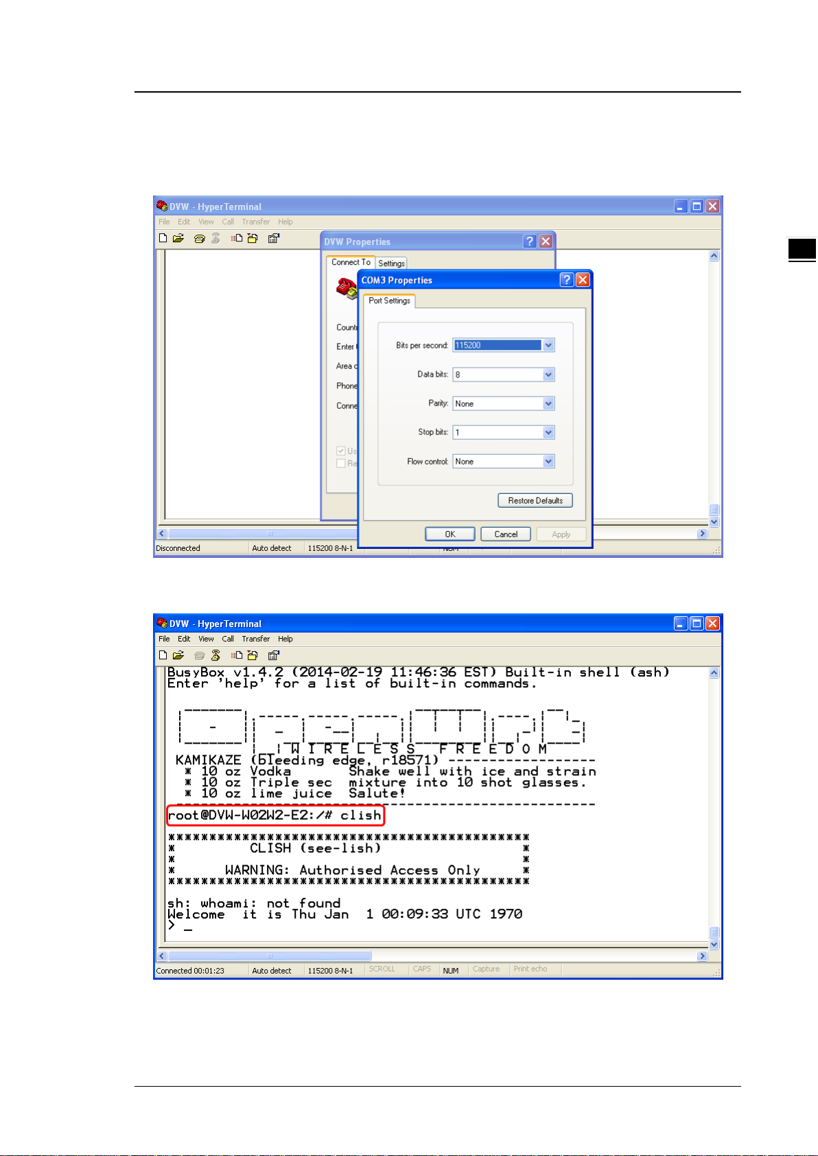
Below is an example to show you how to set the device name.
1. Open terminal software, and select an appropriate COM port for Console Connection, 115200 for Baud
Rate, 8 for Data Bits, None for Parity, and 1 for Stop Bits, None for Flow Control.
2. Type clash and then press Enter.
2-3
Page 16

DVW Series Industrial IEEE 802.11 a/b/g/n Wireless AP/WDS/Client/Gateway User Manual
2_
3. Type system_info_setting and then press Enter.
PS. You can make full by use TAB to complete the command that you want to type.
4. Type set_device_name and the new device n ame, such as “test”, and then press Enter.
2-4
Page 17

Chapter 2 User Interface Introduction
2_
5. The device name had changed to “test”, you can use “get_device_name” to see it.
6. Type exit to exit this CLI session.
2-5
Page 18

DVW Series Industrial IEEE 802.11 a/b/g/n Wireless AP/WDS/Client/Gateway User Manual
2_
7. Sometimes if you don’t know how to use the co mma nd (s uc h as what does this command m ean, or how to
set the parameter in right format, etc), you can type “?” to see the help information.
For example, if you want to set the lo cal tim e to 2 014/02/27 10:11:30, you may know type time_setting and
then type set_local_time, but the next? How should I input the time? You can type ? to see the help
information.
Complete command: “time_setting set_local_time ?” (After you click “?”, the help information will
display.)
8. Finally, you had got to know type 10:11:30 27 02 2014
2-6
Page 19

Chapter 2 User Interface Introduction
2_
2.2 Telnet Console Configuration
Delta DVW device supports telnet server function; it can be globally enabled or disabled. The user
can use all CLI command over a telnet session.
1. Open a Command Prompt and input “telnet 192.168.1.5” to login to Delta DVW device.
2. After input user name and password, you can use CLI command to control the device.
2-7
Page 20
DVW Series Industrial IEEE 802.11 a/b/g/n Wireless AP/WDS/Client/Gateway User Manual
2_
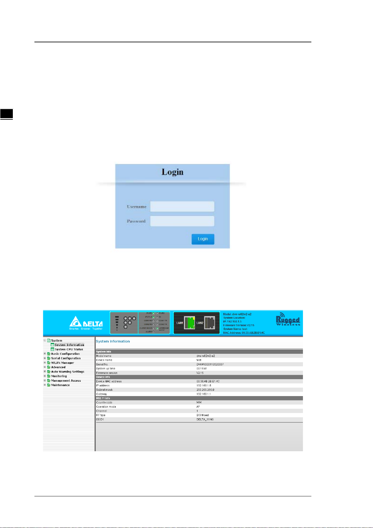
2.3 Web Browser Configuration
Delta DVW devices support a friendly web interface for normal user to configure the switch. You can
monitor the port status of Delta DVW device, and configure the settings of each function via web.
1. Open a web browser and connect to 192.168.1.5 or http://www.deltawifi.net. Input user name
and password.
Username: admin
Password: password
2. You can use the menu tree in left side frame to find the function you want to configure. And
configure the detail settings in right side frame. The port status and LED status on the DVW
device can be monitored on the top frame.
2-8
Page 21

3
Chapter 3 Featured Functions
Table of Contents
3.1 System .................................................................................... 3-4
3.1.1 System Informat ion .................................................................... 3-4
3.1.2 System CPU Status ..................................................................... 3-4
3.2 Basic Configuration ................................................................. 3-5
3.2.1 System Information Configuration ................................................ 3-5
3.2.2 Network Configuration................................................................. 3-5
3.2.3 Time Configuration ..................................................................... 3-8
3.2.3.1 Local Time Configuration .......................................................... 3-8
3.2.3.2 NTP Server Configuration ......................................................... 3-9
3.3 Serial Configuration ............................................................... 3-10
3.3.1 Operation Configuration ............................................................ 3-10
3.3.1.1 M ODBUS ASCII/RTU Slave ...................................................... 3-10
3.3.1.2 MODBUS ASCII/RTU Master ..................................................... 3-12
3.3.1.3 TCP Server Mode .................................................................... 3-15
3.3.1.4 T CP Client Mode ..................................................................... 3-18
3.3.1.5 Virtual COM Mode ................................................................... 3-23
3.3.1.6 UDP Mode ............................................................................. 3-26
3.3.1.7 Pair Connection Mode ............................................................. 3-30
3.3.2 Port Configuration .................................................................... 3-32
3.3.3 MODBUS Cache Table ............................................................... 3-33
3.4 WLAN Manager ...................................................................... 3-36
3.4.1 Operation Mode ........................................................................ 3-36
3.4.1.1 AP Mode ................................................................................ 3-37
3.4.1.2 Client Mode ........................................................................... 3-37
3.4.1.3 Repeater Mode ....................................................................... 3-37
3.4.1.4 WD S Master and Slave Mode ................................................... 3-38
3.4.1.5 Regions ................................................................................. 3-38
3.4.2 WLAN ...................................................................................... 3-39
3.4.2.1 Basic Wireless Configuration – AP Mode .................................... 3-39
3-1
Page 22

DVW Series Industrial IEEE 802.11 a/b/g/n Wireless AP/WDS/Client/Gateway User Manual
3.4.2.2 Basic Wireless Configuration – Client Mode ................................ 3-41
3.4.2.3 Basic Wireless Configuration – Repeater Mode ........................... 3-42
3.4.2.4 Basic Wireless Configuration – Master Mode .............................. 3-44
3.4.2.5 Basic Wireless Configuration – Slave Mode ................................ 3-46
3.4.2.6 Basic Wireless Configuration – Security Mode ............................ 3-48
3.4.3 Advanced Wirel ess Con figuration ................................................. 3-51
3.5 Advanced............................................................................... 3-53
3.5.1 VLAN Configuration.................................................................... 3-53
3.5.2 Packet Control .......................................................................... 3-54
3.5.2.1 Filter Configuration ................................................................. 3-55
3.5.2.2 MAC Filters ............................................................................ 3-55
3.5.2.3 IP Protocol Filters ................................................................... 3-56
3.5.2.4 TCP/UDP Port Filters ............................................................... 3-57
3.5.3 RSTP Configuration .................................................................... 3-57
3.5.4 SNMP Configuration ................................................................... 3-58
3.5.5 Storm Control ........................................................................... 3-60
3.6 Auto Warning Settings .......................................................... 3-61
3.6.1 SysLog ..................................................................................... 3-61
3.6.1.1 Syslog Event Types ................................................................ 3-61
3.6.1.2 Syslog Server Configuration .................................................... 3-63
3.6.2 E-mail Alarm ............................................................................. 3-63
3.6.2.1 E-mail Event Types ................................................................ 3-63
3.6.2.2 E-mail Server Configuration .................................................... 3-64
3.6.3 Relay Alarm .............................................................................. 3-65
3.6.3.1 Relay Event Types .................................................................. 3-65
3.6.4 SNMP Trap ............................................................................... 3-66
3.6.4.1 Trap Event Types ................................................................... 3-66
3.6.4.2 SNMP Trap Receiver Settings ................................................... 3-66
3.7 Monitoring Settings ............................................................... 3-67
3.7.1 Email Alarm Table ..................................................................... 3-67
3.7.2 Relay Alarm Table ..................................................................... 3-67
3.7.3 Trap Alarm Table ....................................................................... 3-68
3.7.4 System Log .............................................................................. 3-68
3.7.5 Network Connection Status ......................................................... 3-69
3.7.6 AP Client List ............................................................................ 3-69
3.7.7 DHCP Client List ........................................................................ 3-69
3-2
Page 23

Chapter 3 Featured Function
3_
3.7.8 Serial Port State ....................................................................... 3-70
3.7.9 Serial Port Statistics .................................................................. 3-70
3.7.10 Serial Port Error ....................................................................... 3-70
3.7.11 Serial Port Log ......................................................................... 3-70
3.8 Management Access .............................................................. 3-71
3.8.1 SSH Configuration .................................................................... 3-71
3.8.2 Telnet Configuration.................................................................. 3-71
3.9 Maintenance .......................................................................... 3-72
3.9.1 Session Timeout ....................................................................... 3-72
3.9.2 Password ................................................................................. 3-72
3.9.3 Ping ........................................................................................ 3-73
3.9.4 Firmware Upgrade .................................................................... 3-74
3.9.5 Log Export ............................................................................... 3-74
3.9.6 Config Import Export ................................................................ 3-74
3.9.7 Reset to Default ....................................................................... 3-75
3.9.8 Reboot .................................................................................... 3-75
3.9.9 Logout .................................................................................... 3-75
3-3
Page 24

DVW Series Industrial IEEE 802.11 a/b/g/n Wireless AP/WDS/Client/Gateway User Manual
3.1 System
This group includes System Information and System CPU Status.
3.1.1 System Information
This page summarizes the current st atus of system. T he inf ormati on i s categoriz ed into seve ral group s: Sy stem
Info, Device Info and 802.11 Info.
3.1.2 System CPU Status
This page summarizes the current status of CPU. It includes Running Time, Total Powered Time, CPU Usa ge,
RAM Total and RAM Available. These values should be grayed out and could not be edited.
3-4
Page 25

Chapter 3 Featured Function
3_
3.2 Basic Configuration
The basic configuration grou p includes most commo n settin gs, an d admin istrat or can maint ain c ontr ol the D V W
wireless devices in this group.
3.2.1 System Information Configuration
The System Information Configuration includes Device name, Device location, Device description and Device
contact information. By default, the Device name is DVW-W02W2-E2 and the Device description is Series
Industrial IEEE 802.1 1a/b/g/n wireless AP/bridge/cli ent.
Item Description Factory Default
Device name
Device location This field displays the location of the
Device description
Device contact
information
This field displays the name of the device.
The default value is the model name.
device.
This field displays the description of the
device.
This field displays t he contact inform atio n o f
the device.
DVW-W02W2-E2
None
Industrial IEEE 802.11a/b/g/n
wireless AP/WDS/Client/G ateway
None
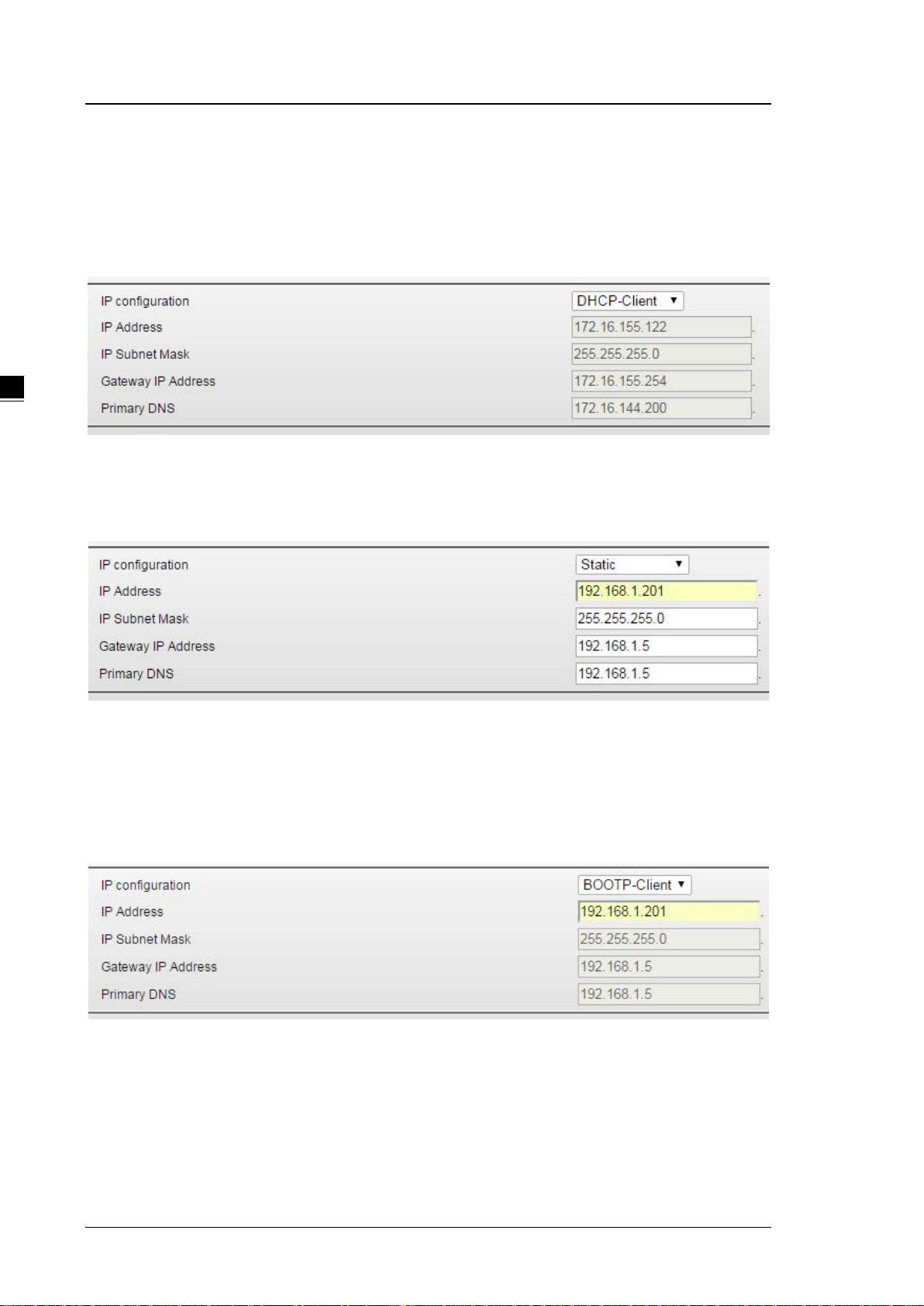
3.2.2 Network Configuration
The Network Configuration allows you to modify IP Configuration, IP Address, IP Subnet Mask, Gateway IP
Address and Primary DNS. From the IP configuration, there are various options under the Multi-Mode,
including DHCP-Client, Static, BOOTP-Client and DHCP-Server for users to choose from.
3-5
Page 26
DVW Series Industrial IEEE 802.11 a/b/g/n Wireless AP/WDS/Client/Gateway User Manual
DHCP-Client:
If there is a DHCP server on the network, and the DVW series is in DHCP-client mode , the DVW series can
receive requests from the DHCP server. If there is no DHCP server presented on the network, the IP address
will be configured to 192.168.1.5 and the IP subnet mask to 255.255.255.0.
Static:
Users can define the IP Address, IP Subnet Mask, Gateway IP Address and Primary DNS.
BOOTP-Client:
If there is a BOOTP server on the network, and the DVW series is in BOOTP mode, the DVW series can
receive requests from the BOOTP server. If there is no BOOTP server presented on the network, the IP
address will be configured to 192.168.1.5 and the IP subnet mask to 255.255.255.0.
DHCP-Server:
When the DHCP server receives req ues t s fr om t he end clients, the DVW series will assign a Dynamic IP
Address to other clients. When the DHCP-Se rver and BOOTP-Server coexist and are activated at the
same time, the IP address will be configured to 192.168.1.5 and IP subnet mask to 255.255.255.0.
3-6
Page 27

3_
The DHCP pool will start from 192.168.1.1 to 192.168.1.254.
Description Factory Default
IP Configuration
Specify the IP st at us of the network interface.
DHCP-Client: The DVW series receives its IP configuration settings from
Chapter 3 Featured Function
the DHCP server.
Static: Specify the static IP address manually.
BOOTP-Client: The DVW series receives its IP configuration settings
from the BOOTP server.
DHCP-Client
DHCP-Server: When the DHCP server receives requests from the end
clients, the DVW series will assign a Dy namic IP Ad dress to other client s.
IP Address
Input the IP address of the network interface. 192.168.1.5
IP Subnet Mask
Input the IP subnet mask of the network interface. 255.255.255.0
Gateway IP Address
Input the default gateway of the network interface. 0.0.0.0
Primary DNS
Input the primary DNS address of the network interface. 0.0.0.0
Notice:
If the Operation Mode has changed to Salve Mode, you cannot configure the network
settings. (Grayed out). For details, please refer to section 3.4.1.4 WDS Master Mode / Slave
Mode for more information.
3-7
Page 28

DVW Series Industrial IEEE 802.11 a/b/g/n Wireless AP/WDS/Client/Gateway User Manual
Description Factory Default
3.2.3 Time Configuration
3.2.3.1 Local Time Configuration
The local time can be set manually or get from NTP server dynamically. In order to get local time dynamically,
user should configure the time zone and time servers correctly. If it belongs to DST area, please also enable
“Automatically adjust for daylight savings time”.
The Current local time shows the DVW’s syst em t ime w hen y ou open thi s web page. You can click on the Set
Time button to activate the updated date and time parameters.
Description Factory Default
Current local time
The date and time can be configured as local time. The 24-hour format: None
3-8
Page 29

3_
YYYY/MM/DD HH: MM:SS
Time zone
Chapter 3 Featured Function
Description Factory Default
The time zone setting can be configured as conversio n fro m GM T (Greenwich
Mean Time) to local time.
Automatically adjust for daylight savings time
Daylight saving time (DST) also summer time is the practice of advancing
clocks during the lighter months so that evenings have more daylight and
mornings have less.
Time server 1/2
Specify the IP address or domain name of NTP time server. The time of the
second server will be used if the first serv er can’t be connec t ed.
Notice:
It is highly suggested that users manually set up the device time in the following situations,
when there is no NTP time server or no internet connection or when the device has not been
operated for a long time, or for the initial setup .
GTM+08:00
Disabled
Enabled
3.2.3.2 NTP Server Configuration
When Delta DVW series get valid local time, DVW series can enable NTP Server to supply the time service for
LAN clients.
Description Factory Default
NTP server
Specify whether the NTP server is enabled.
Enable: The NTP server function is enabled.
Disabled
3-9
Page 30
DVW Series Industrial IEEE 802.11 a/b/g/n Wireless AP/WDS/Client/Gateway User Manual
Description Factory Default
Disable: The NTP server function is disabled.
NTP server 1/2
Specify the IP address or domain name of NTP server of DVW series. The
second NTP server will be used if the first NTP server can’t be connected.
www.deltawifi.com
www.deltawifi.net
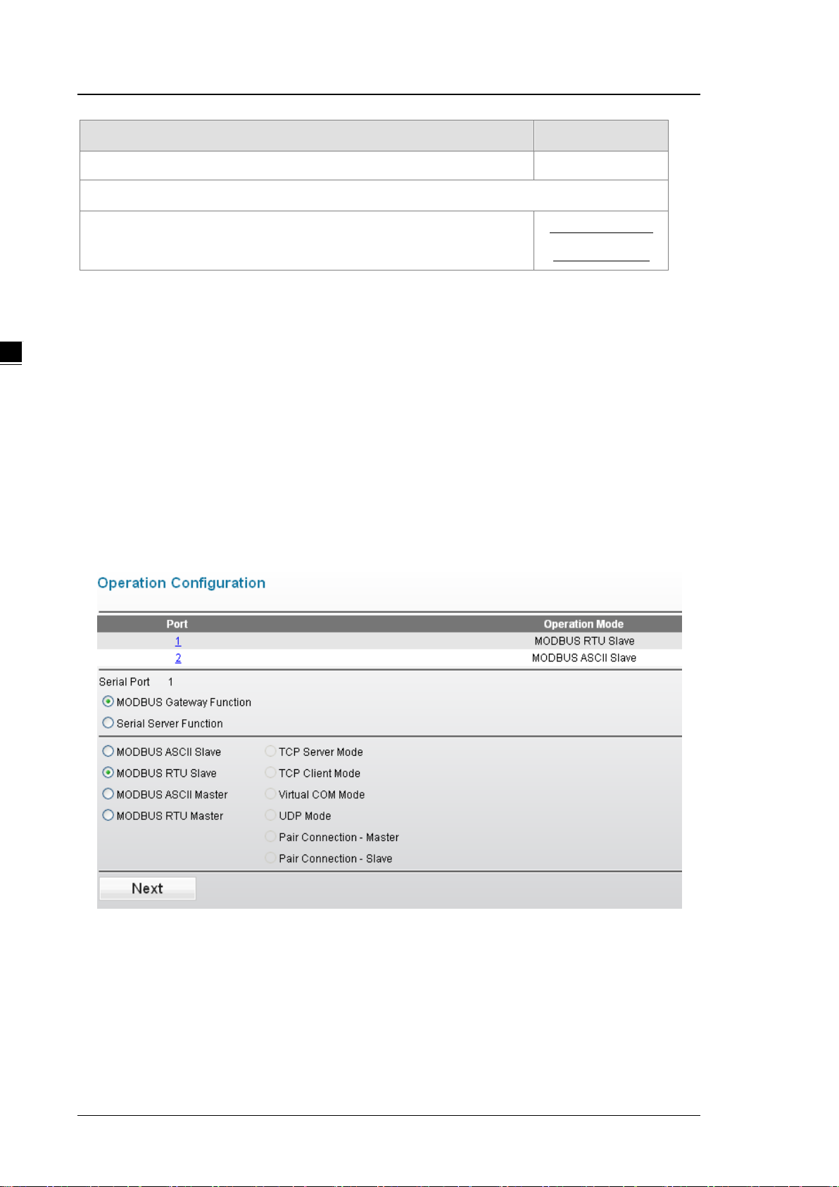
3.3 Serial Configuration
DVW provides 2 kinds of serial function, MODBUS Gateway function and Serial Server function. MODBUS
Gateway function can convert data from MODBUS to Ethernet or from Ethernet to MODBUS. Serial Server
includes different modes for different interaction in the network.
3.3.1 Operation Configuration
If users have requirement about MODBUS Gateway function, DVW series provides MODBUS ASCII/RTU
Slave mode and MODBUS ASCII/RTU Master mode. If you have requirement about Serial Server function,
DVW series provides TCP Server mode, TCP Client mode, Virtual COM mode, UDP mode, Pair Connection
mode – Master and Pair Connection mode – Slave.
3.3.1.1 MODBUS ASCII/RTU Slave
When a MODBUS master device send a request message to MODBUS slave device, the MODBUS slave
device will forward the message according to the slave ID. If the same slave ID is being used in serial network,
then the communication will have problem.
Slave ID Map function can h elp you to create a map ID for the devices which has the sa me r eal Sta tion ID. You
3-10
Page 31

Chapter 3 Featured Function
3_
can specify the range of map I D on ea ch seria l port , and th en DV W series will f orw ard the m essage t o the ser ial
device according to the map ID table.
Description Factory Default
Operation Mode
Display the operation mode of serial port. MODBUS ASCII
Slave
Station ID
3-11
Page 32

DVW Series Industrial IEEE 802.11 a/b/g/n Wireless AP/WDS/Client/Gateway User Manual
Description Factory Default
Specify the station ID of the device.
TCP Alive Time
Specify how long the DV W series keeps the TCP session when there is no
TCP activity in specified time. If the time is “0”, then the connection will remain
open.
Response Timeout
Specify how long the DV W series waits the response from the serial device. 3000
Retry
Specify the retry time when the time of Response Timeout reached. 3
MODBUS Exception
Specify whether the device s e nd an exception code back t o t he c lie nt when the
response timeout is reached.
Slave ID Map
Port 1: 246
Port 2: 247
30
Enabled
Specify the mapping table of slave ID.
Slave ID Range: Enter the range of real slave ID.
Map ID Range: Enter the range of virtual slave ID which DVW series can
create.
Priority
Specify the priority of the serial device. None
None
3.3.1.2 MODBUS ASCII/RTU Master
If the serial device that connect to DV W series has Ethernet interface, you can specify the station address and
destination IP address in forward table. DVW series follows the forward table to forward data to correct serial
devices.
3-12
Page 33

Chapter 3 Featured Function
3_
Description Factory Default
Operation Mode
Display the operation mode of serial port. MODBUS ASCII
Master
Station ID
Specify the station ID of the device.
TCP Alive Time
Specify how long the DV W series keeps the TCP session when there is no
TCP activity in specified time. If the time is “0”, then the connection will remain
open.
Response Timeout
Specify how long the DV W series waits the response from the serial device. 3000
Port 1: 246
Port 2: 247
30
3-13
Page 34

DVW Series Industrial IEEE 802.11 a/b/g/n Wireless AP/WDS/Client/Gateway User Manual
Description Factory Default
Retry
Specify the retry time when the time of Response Timeout reached. 3
MODBUS Exception
Specify whether the device s e nd an exception code back t o t he c lie nt when the
response timeout is reached.
Enabled
Forward Table
Description Factory Default
Enable
Specify whether the forward information is enabled. Unticked
Local Port
The local port of DV W series will create automatically.
Port 1: 8000~8031
Port 2: 9000~9031
Station Addr ess
Specify the station ID of serial devices. None
Destination IP Address
8000~8031
9000~9031
Specify the IP address of serial devices. None
3-14
Page 35

Chapter 3 Featured Function
3_
3.3.1.3 TCP Server Mode
In TCP Server Mode, DVW series works as a passive role. D VW series waits the connected requirement from
the host computer or device. The host must send a request message to DVW series for establish the
connection first. After the connection is established, the data can be transmitted between the host and DVW
series.
Description Factory Default
Operation Mode
Display the operation mode of serial port. TCP Server Mode
Alive Check Time
Specify how long the DV W series sends a packet for checking the connection
still alive.
Disconnect Time
Specify how long the DV W series keeps the TCP session when there is no
TCP activity in specified time. If the time is “0”, then the connection will remain
open.
TCP Port
Specify the port number of DV W series. 3000
30
3000
3-15
Page 36

DVW Series Industrial IEEE 802.11 a/b/g/n Wireless AP/WDS/Client/Gateway User Manual
Description Factory Default
Fixed Length
Specify whether sends the packet with fixed length. When the receiving data
length matches with the configured value, the data will be sent.
Notice:
Before you enter the value of fixed length, please remember to tick
the Enable option, otherwise the Fixed Len gth f unc tio n doesn’t work.
Prefix
Specify the Prefix Length and Prefix Process of data.
Notice:
Before you configure the settings of Prefix Length, Prefix Char and
Prefix Process, please remember to tick the Enable option,
Disabled/1024
Disabled
otherwise the Prefix function doesn’t work.
Prefix Length
Specify the Prefix Length for comparison process. After specify the Prefix
Length, please enter the Prefix Char for process.
3-16
2
Page 37

Chapter 3 Featured Function
3_
uffix Char (Hex.). If the Suffix Length is 1, then only first Suffix
Description Factory Default
Prefix Char (Hex.)
Enter the Prefix Char for comparison process. FF, FF
Prefix Process
Specify the comparison process for the Prefix Length and Prefix Char.
Include Prefix Char: The data will transmit all the Prefix Char which user
entered in Prefix Char (Hex.). If the Prefix Length is 1, then only first Char
will be included.
Only Prefix Char 2: The data will transmit only Prefix Char 2 which user
entered in Prefix Char (Hex.).
Not Include: After the comparison process is complete, the data will be
transmitted without Prefix Char which the user entered in Prefix Char
(Hex.).
Suffix
Specify the Suffix Length and Suffix Process of data.
Notice:
Before you configure the settings of Suffix Length, Suffix Char and
Suffix Process, please remember to tick the Enable option,
otherwise the Suffix function doesn’t work.
Suffix Length
Specify the Suffix Length for comparison process. After specify the Suffix
Length, please enter the Suffix Char for process.
Include prefix
character
Disabled
2
Suffix Char (Hex.)
Enter the Suffix Char for comparison process. FF, FF
Suffix Process
Specify the comparison process for the Suffix Length and Suffix Char.
Include Suffix Char: The data will transmit all the Suffix Char which user
entered in S
Char will be included.
Only Suffix Char 1: The data will transmit only Suffix Char 1 which user
entered in Suffix Char (Hex.).
Not Include: After the comparison process is complete, the data will be
transmitted without Suffix Char which the user entered in Suffix Char
(Hex.).
Include suffix
character
3-17
Page 38

DVW Series Industrial IEEE 802.11 a/b/g/n Wireless AP/WDS/Client/Gateway User Manual
Description Factory Default
Aging Time
Specify the time for DVW series to force pack the received serial data into the
same data frame.
Notice:
Before you configure the settings of Agi ng Time, pleas e reme mber to
tick the Enable option, otherwise the Aging Time doesn’t be applied.
Disabled/
1000 (ms)
3.3.1.4 TCP Client Mode
In TCP Client Mode, DVW series works as an active role. User can enter the destination IP information of the
host computer or device in Destination IP Table first. Then DVW series sends a request message to the host
for establish the connection first. After the connection is established, the data can be transmitted between the
host and DVW series.
3-18
Page 39

Chapter 3 Featured Function
3_
Description Factory Default
Operation Mode
Display the operation mode of serial port. TCP Client Mode
Alive Check Time
Specify how long the DV W series sends a packet for checking the connection
still alive.
Disconnect Time
Specify how long the DVW series keeps the TCP session when there is no
TCP activity in specified time. If the time is “0”, then the connection will remain
open.
30
3000
3-19
Page 40

DVW Series Industrial IEEE 802.11 a/b/g/n Wireless AP/WDS/Client/Gateway User Manual
Destination IP Table
Description Factory Default
Enable
Specify whether the destination IP information is enabled. Unticked
Local Port
Specify the local listen port of DVW series for the specified destination device
which uses to establish the connection, ranging from 1024 to 65535.
Destination IP Address
Specify the IP address of the Ethernet device. None
Remote Port
Specify the port number of the Ethernet device, ranging from 1024 to 65535. 8000
8000-8007
3-20
Page 41

3_
Data Packing
Description Factory Default
Fixed Length
Specify whether sends the packet with fixed length. When the receiving data
length matches with the configured value, the data will be sent.
Notice:
Before you enter the value of fixed length, please remember to tick
Chapter 3 Featured Function
Disabled/
1024
the Enable option, otherwise t he F ixed Length function do es n’t work.
Prefix
Specify the Prefix Length and Prefix Process of data.
Notice:
Before you configure the settings of Prefix Length, Prefix Char and
Disabled
Prefix Process, please remember to tick the Enable option,
otherwise the Prefix function doesn’t work.
Prefix Length
Specify the Prefix Length for comparison process. After specify the Prefix
2
Length, please enter the Prefix Char for process.
Prefix Char (Hex.)
Enter the Prefix Char for comparison process. FF, FF
Prefix Process
Specify the comparison process for the Prefix Length and Prefix Char.
Include Prefix Char: The data will transmit all the Prefix Char which user
entered in Prefix Char (Hex.). If the Prefix Length is 1, then only first Char
will be included.
Only Prefix Char 2: The data will transmit only Prefix Char 2 which user
entered in Prefix Char (Hex.).
Include prefix
Not Include: After the comparison process is complete, the data will be
character
transmitted without Prefix Char which the user entered in Prefix Char
(Hex.).
3-21
Page 42

DVW Series Industrial IEEE 802.11 a/b/g/n Wireless AP/WDS/Client/Gateway User Manual
Description Factory Default
Suffix
Specify the Suffix Length and Suffix Process of data.
Notice:
Before you configure the settings of Suffix Length, Suffix Char and
Suffix Process, please remember to tick the Enable option,
Disabled
otherwise the Suffix function doesn’t work.
Suffix Length
Specify the Suffix Length for comparison process. After specify the Suffix
2
Length, please enter the Suffix Char for process.
Suffix Char (Hex.)
Enter the Suffix Char for comparison process. FF, FF
Suffix Process
Specify the comparison process for the Suffix Length and Suffix Char.
Include Suffix Char: The data will transmit all the Suffix Char which user
entered in Suffix Char (Hex.). If the Suffix Length is 1, then only first Suffix
Char will be included.
Include suffix
Only Suffix Char 1: The data will transmit only Suffix Char 1 which user
character
entered in Suffix Char (Hex.).
Not Include: After the comparison process is complete, the data will be
transmitted without Suffix Char which the user entered in Suffix Char
(Hex.).
Aging Time
Specify the time for DVW series to force pack the receiv ed se rial dat a into the
same data frame.
Notice:
Before you configure t he sett ings of Agi ng Time, please remember to
tick the Enable option, other w ise the Aging Time doesn’t be applied.
3-22
Disabled/
1000 (ms)
Page 43

Chapter 3 Featured Function
3_
3.3.1.5 Virtual COM Mode
In Virtual COM mode, DVW series can establish a network connection between the host computer and serial
device. So the DVW series maps the IP address with port number to the serial port on itself. When the
application on host computer doesn’t provide serial interface to connect with serial device, then Virtual COM
mode can solve this problem and establish a Virtual COM connection on Ethernet interface.
Description Factory Default
Operation Mode
Display the operation mode of serial port. Virtual COM Mode
Alive Check Time
Specify how long the DV W series sends a packet for checking the connection
still alive.
Disconnect Time
Specify how long the DV W series keeps the TCP session when there is no
TCP activity in specified time. If the time is “0”, then the connection will remain
open.
TCP Port
Specify the port number of DV W series. 3000
30
3000
3-23
Page 44

DVW Series Industrial IEEE 802.11 a/b/g/n Wireless AP/WDS/Client/Gateway User Manual
Data Packing
Description Factory Default
Fixed Length
Specify whether sends the packet with fixed length. When the receiving data
length matches with the configured value, the data will be sent.
Notice:
Before you enter the value of fixed length, please remember to tick
Prefix
Specify the Prefix Length and Prefix Process of data.
the Enable option, otherwise t he F ixed Length function do es n’t work.
Notice:
Before you configure the settings of Prefix Length, Prefix Char and
Disabled/
1024
3-24
Prefix Process, please remember to tick the Enable option,
otherwise the Prefix function doesn’t work.
Disabled
Page 45

3_
Prefix Length
entered in Suffix Char (Hex.). If the Suffix Length is 1, then only first Suffix
Chapter 3 Featured Function
Description Factory Default
Specify the Prefix Length for comparison process. After specify the Prefix
2
Length, please enter the Prefix Char for process.
Prefix Char (Hex.)
Enter the Prefix Char for comparison process. FF, FF
Prefix Process
Specify the comparison process for the Prefix Length and Prefix Char.
Include Prefix Char: The data will transmit all the Prefix Char which user
entered in Prefix Char (Hex.). If the Prefix Length is 1, then only first Char
will be included.
Include prefix
Only Prefix Char 2: The data will transmit only Prefix Char 2 which user
character
entered in Prefix Char (Hex.).
Not Include: After the comparison process is complete, the data will be
transmitted without Prefix Char which the user entered in Prefix Char
(Hex.).
Suffix
Specify the Suffix Length and Suffix Process of data.
Notice:
Before you configure the settings of Suffix Length, Suffix Char and
Disabled
Suffix Process, please remember to tick the Enable option,
otherwise the Suffix function doesn’t work.
Suffix Length
Specify the Suffix Length for comparison process. After specify the Suffix
2
Length, please enter the Suffix Char for process.
Suffix Char (Hex.)
Enter the Suffix Char for comparison process. FF, FF
Suffix Process
Specify the comparison process for the Suffix Length and Suffix Char.
Include Suffix Char: The data will transmit all the Suffix Char which user
Include suffix
character
Char will be included.
3-25
Page 46

DVW Series Industrial IEEE 802.11 a/b/g/n Wireless AP/WDS/Client/Gateway User Manual
Description Factory Default
Only Suffix Char 1: The data will transmit only Suffix Char 1 which user
entered in Suffix Char (Hex.).
Not Include: After the comparison process is complete, the data will be
transmitted without Suffix Char which the user entered in Suffix Char
(Hex.).
Aging Time
Specify the time for DVW series to force pack the received serial data into the
same data frame.
Notice:
Before you configure t he sett ings of Agi ng Time, please remember to
tick the Enable option, other w ise the Aging Time doesn’t be applied.
Disabled/
1000 (ms)
3.3.1.6 UDP Mode
Compare with TCP communication, UDP communication doesn’t need request message before the session
has been established. So after user configure the remote IP address and port information, the device will start
to transmit the data. You can use unicast or multicast way to transmit data between the host computer and
serial device.
3-26
Page 47

Chapter 3 Featured Function
3_
Forward Table
Description Factory Default
Enable
Specify whether the forward information is enabled. Unticked
Local Port
Specify the local listen port of DVW series for the device which uses to
establish the connection.
Begin IP Address
Specify the beginning of destination IP address. None
End IP Address
Specify the end of destination IP address. None
Remote Port
Specify the port number of the Ethernet device. None
8000-8003
3-27
Page 48

DVW Series Industrial IEEE 802.11 a/b/g/n Wireless AP/WDS/Client/Gateway User Manual
Data Packing
Description Factory Default
Fixed Length
Specify whether sends the packet with fixed length. When the receiving data
length matches with the configured value, the data will be sent.
Notice:
Before you enter the value of fixed length, please remember to tick
the Enable option, otherwise t he F ixed Length function do es n’t work.
Disabled/
1024
Prefix
Specify the Prefix Length and Prefix Process of data.
Notice:
Before you configure the settings of Prefix Length, Prefix Char and
Disabled
Prefix Process, please remember to tick the Enable option,
otherwise the Prefix function doesn’t work.
Prefix Length
Specify the Prefix Length for comparison process. After specify the Prefix
2
Length, please enter the Prefix Char for process.
Prefix Char (Hex.)
Enter the Prefix Char for comparison process. FF, FF
Prefix Process
Specify the comparison process for the Prefix Length and Prefix Char.
Include Prefix Char: The data will transmit all the Prefix Char which user
entered in Prefix Char (Hex.). If the Prefix Length is 1, then only first Char
will be included.
Only Prefix Char 2: The data will transmit only Prefix Char 2 which user
entered in Prefix Char (Hex.).
Not Include: After the comparison proc es s is complete, the data will be
transmitted without Prefix Char which the user entered in Prefix Char
(Hex.).
Include prefix
character
3-28
Page 49

3_
Description Factory Default
Suffix
Specify the Suffix Length and Suffix Process of data.
Notice:
Before you configure the settings of Suffix Length, Suffix Char and
Suffix Process, please remember to tick the Enable option,
Chapter 3 Featured Function
Disabled
otherwise the Suffix function doesn’t work.
Suffix Length
Specify the Suffix Length for comparison process. After specify the Suffix
2
Length, please enter the Suffix Char for process.
Suffix Char (Hex.)
Enter the Suffix Char for comparison process. FF, FF
Suffix Process
Specify the comparison process for the Suffix Length and Suffix Char.
Include Suffix Char: The data will transmit all the Suffix Char which user
entered in Suffix Char (Hex.). If the Suffix Length is 1, then only first Suffix
Char will be included.
Include suffix
Only Suffix Char 1: The data will transmit only Suffix Char 1 which user
character
entered in Suffix Char (Hex.).
Not Include: After the comparison process is complete, the data will be
transmitted without Suffix Char which the user entered in Suffix Char
(Hex.).
Aging Time
Specify the time for DVW series to force pack the received serial data into the
same data frame.
Notice:
Before you configure t he sett ings of Agi ng Time, please remember to
tick the Enable option, other w ise the Aging Time doesn’t be applied.
Disabled/
1000 (ms)
3-29
Page 50

DVW Series Industrial IEEE 802.11 a/b/g/n Wireless AP/WDS/Client/Gateway User Manual
3.3.1.7 Pair Connection Mode
Pair Connection Master and Slave modes connect two DVW series over a network. The serial device can
connect to a DVW series, and two DVW can use wired Ethernet cable or wireless way to connect each other.
Then two serial devices can overcome the distance limitation of serial interface.
Pair Connection Master Mode
Description Factory Default
Operation Mode
Display the operation mode of serial port. Pair Connection -
Master
Alive Check Time
Specify how long the DV W series sends a packet for checking the connection
30
still alive.
Destination IP
Specify the IP address for the destination DVW series with Pair Connection
None
Slave mode.
Destination Port
Specify the port number for the destination DVW series with Pair Connection
None
Slave mode.
3-30
Page 51

Chapter 3 Featured Function
3_
Pair Connection Slave Mode
Description Factory Default
Operation Mode
Display the operation mode of serial port. Pair Connection -
Slave
Alive Check Time
Specify how long the DV W series keeps the connection. If the time is “0”, then
the connection will remain open.
TCP Port
Specify th e p or t num ber for the DVW series with Pair Connection Master mo de
to connect.
30
None
3-31
Page 52

DVW Series Industrial IEEE 802.11 a/b/g/n Wireless AP/WDS/Client/Gateway User Manual
3.3.2 Port Configuration
You can view the current communication settings for each serial port in this page. If you need to configure the
settings,
Parameter Value
Interface RS232, RS485, RS422
Data bit 7, 8
Parity bit None, Even, Odd, Space, Mark
Stop bit 1, 2
Baud rate 110 to 921600 bps
Flow Control None, RTS/CTS, XON/XOFF
Buffer Size 10 (Default Value, not available in MODBUS Gateway Funciton)
3-32
Page 53

Chapter 3 Featured Function
3_
3.3.3 MODBUS Cache Table
The transmit speed of Ethernet interface is faster than serial interface, so the device on Ethernet side usually
need to spend much time to wait the data from serial s ide aft er th ey se nd t he req uest message to the dev ice on
serial side. MODBUS Cache Table provide user for configure the device information (ex. Station ID, MODBUS
address…etc.), and DVW can send request message for get the data from the device on serial side according
to the MODBUS Cache table in advance. When the device on Ethernet side sends the request to DVW series,
then DVW can response the data immediately. Because DVW series don’t need to forward the request
message to the device on serial side again, it already get the data in advance. So this only can be enabled
when the operation mode in MODBUS Slave mode.
Read data in MODBUS Cache mode
Read data in Non MODBUS Cache Table mode
3-33
Page 54

DVW Series Industrial IEEE 802.11 a/b/g/n Wireless AP/WDS/Client/Gateway User Manual
Description Factory Default
Enable
Specify whether the MODBUS Cache function is enabled. Unticked
Cycle time
Specify the time of sending request message with serial devices. 10
Available size
Display the remaining s ize for the dat a c an be monitor ed. 1M B size c an incl ude
100,000 data.
Timeout Calibration
Display the adjusted time of Response Timeout. When user click the Detect
button, DVW series will communicate with the device according to the
MODBUS Cache table
1048576 (fixed)
3000 (fixed)
Coil Device
Item Description
Stat ion Address The station ID of the device.
MODBUS (Hex.) The MODBUS address in hexadecimal.
MODBUS (Dec.) The MODBUS address in decimal.
State The value of the MODBUS address.
3-34
Page 55

3_
Word Device
Item Description
Stat ion Address The station ID of the device.
MODBUS (Hex.) The MODBUS address in hexadecimal.
MODBUS (Dec.) The MODBUS address in decimal.
Present Value The present value of the MODBUS address.
Format The format of the value as Hex, Dec or Bin.
Chapter 3 Featured Function
Description Factory Default
Station Addr ess
The station ID of the device. None
MODBUS (Hex.)
The MODBUS address in hexadecimal. None
MODBUS (Dec.)
The MODBUS address in decimal. None
Account
The amount of MODBUS data can be monitored. None
Format
Specify the format of the value as Hex, or Dec. Hex
Online
Specify whether the data display in MODBUS monitored table. Unticked
3-35
Page 56

DVW Series Industrial IEEE 802.11 a/b/g/n Wireless AP/WDS/Client/Gateway User Manual
3.4 WLAN Manager
The device should support AP mode, Client mode, Repeater mode and WDS (Master/Slave) mode.
3.4.1 Operation Mode
Delta DVW series provides 5 oper ation modes f or you t o conf igure i n dif ferent n etw ork envir onment . Befor e yo u
establish your wireless network, you must specify an operation mode on DVW series.
Description Factory Default
Wireless enable
Specify whether the wireless is enabled or not.
Enable: Wireless function can work.
Disable: Wireless function can’t work.
Operation mode
Specify the wireless operation mode:
AP: Specify DVW series work as AP mode.
Client: Specify DVW series work as Client mode.
Repeater: Specify DVW series work as Repeater mode.
Master: Specify DVW series work as a WDS Master mode.
Slave: Specify DVW series work as a WDS Slave mode.
Region
Disabled
AP
Specify the country where the device locates. English Mode: Europe
Chinese Mode: Asia
Notice:
If you click Cancel button, GUI will revoke all your input and revoke to previous settings, then return
to “Basic Wireless Configuration” page.
3-36
Page 57

Chapter 3 Featured Function
3_
3.4.1.1 AP Mode
When DVW series configures as AP (Access Point) mode, it can provide the connec tiv ity for wireless cl ient.
Please refer to section 3.4.2.1 Basic Wireless Configuration – AP Mode for more information.
3.4.1.2 Client Mode
When DVW series configures as Client mode, it can provides LAN -to-WLAN connection type. If a cl ien t doe sn’ t
equipped wireless card, it can use Ethernet cable connect to D VW series which be configured as Client mode,
and have a connection with another AP. Please refer to section 3.4.2.2 Basic Wireless Configuration – Client
Mode for more information.
3.4.1.3 Repeater Mode
When DVW series configures as Repeater mode, it can extend the wireless distance between two wireless
devices. It supports AP mode and Client mode concurrently. You can set more than one repeater between two
wireless devices, but it will affect the throughput. Please refer to section 3.4.2.3 Basic Wireless Configuration –
Repeater Mode for more information.
3-37
Page 58

DVW Series Industrial IEEE 802.11 a/b/g/n Wireless AP/WDS/Client/Gateway User Manual
3.4.1.4 WDS Master and Slave Mode
When the DVW series configur es as WDS Master mode, it will be en abl ed as a Base Station. User ca n ad d th e
MAC address of the repeaters. Up to 4 repeaters can be added. Please refer to section 3.4.2.4 Basic Wireless
Configuration – WDS Master Mode for more information.
When the DVW series configures as WDS Slave mode, it will be enabled as a Repeater. User can add the
MAC address of the base station. Please refer to section 3.4.2 .5 Basic Wirel ess Configuration – WDS Slave
Mode for more information.
3.4.1.5 Regions
There are different regulations for wireless channels in different regions. Countries apply their own regulations
to the allowable channels, allowed user and maximum power levels within these frequency ranges. The DVW
series supports the wireless channels for the following countries, Africa, Asia, Australia, Canada, China,
Europe, India, Israel, Japan, Korea, Malaysia, Mexico, Middle East (Algeria, Syria, Yemen, Iran, Lebanon,
Qatar, Turkey, Egypt, Tunisia, Kuwait, Saudi Arabia, U nited Ar ab Emirates) , Russ ia, Sin gapore, S outh Ameri ca,
Taiwan, and the United States.
3-38
Page 59

Chapter 3 Featured Function
3_
3.4.2 WLAN
There are different wireless configurations for various operation modes, including AP mode, Client mode,
Repeater mode, WDS Master mode, and WDS slave mode.
3.4.2.1 Basic Wireless Configuration – AP Mode
After you specify the Operation Mode, please add a SSID in Basic Wireless Configuration page. And click Edit
button to configure the wireless settings.
Notice:
Please remember to click the“Apply” button to have the new wireless setting s applied. If there is any
change on the wireless settings, a reminder will show up under the“Add-SSID” button.
3-39
Page 60

DVW Series Industrial IEEE 802.11 a/b/g/n Wireless AP/WDS/Client/Gateway User Manual
Description Factory Default
Operation Mode
Display the current operation mode. AP mode
RF Type
2.4GHz
B: only support IEEE 802.11b mode
G: only support IEEE 802.11g mode
B/G Mixed: support IEEE 802.1 1b/g mixed mode
G/N Mixed: support IEEE 802.11g/n mixed mode, but not IEEE 802.11b
mode
B/G/N Mixed: support IEEE 802.11b/g/n mixed mode
N Only (2.4GHz): only support IEEE 802.11n mode
5GHz
None
A : only support IEEE 802.11a mode
A/N Mixed: IEEE 802.11a/n mixed mode
N Only (5GHz): only support IEEE 802.11n mode
Channel
2.4GHz
Canada, Mexico, Taiwan, the United States: 1-11
The rest of the above-mentioned countries: 1~13
5GHz
Asia, Australia, Canada, India, Israel, Malaysia, Mexico, Singapore,
South America, the United States:
A/N mixed mode: 36, 40, 44, 48, 149, 153, 157, 161, 165
5GHz mode: 36, 40, 44, 48, 149, 153, 157, 161
Korea: 36, 40, 44, 48, 149, 153, 157, 161
China, Middle East (Iran, Lebanon, Qatar):
A/N mixed mode: 149, 153, 157, 161, 165
None
5GHZ mode: 149, 153, 157, 161
Middle East (Saudi Arabia): A/N mixed mode: 149, 153, 157, 161, 165
Taiwan:
A/N mixed mode: 56, 60, 64, 149, 153, 157, 161, 165
5GHz mode: 60, 64, 149, 153, 157, 161
3-40
Page 61

3_
Description Factory Default
For the rest of the above mentioned countries: 36, 40, 44, 48
SSID
Chapter 3 Featured Function
Specify the n am e of wireless device. It is not case sensitiv e. You can input 1 to
32 characters for SSID and space is also allowed.
SSID broadcast
Specify whether the SSID broadcast is enabled.
Enable: SSID can be broadcast.
Disable: SSID can’t be broadcast.
Security mode
Please refer to section 3.4.2.6 Wireless Security Settings section. None
Notice:
Before connecting the wireless device to the DVW series in the AP mode, please check if the network
environment is with the DHCP-Server. If not, please set the IP configurations of the DVW series to
DHCP-Server or manually set the IP address of the wireless device to the same network segment of the DVW
series. Otherwise, DVW series may not be able to connect to the wireless device.
DELTA_11NG
Enabled
3.4.2.2 Basic Wireless Configuration – Client Mode
If you configure the O peration Mode to Client Mode, the Site Survey but to n will be shown on the Basic Wireless
Configuration page. Cl ick the “ Site Surv ey” butt on and then a “ Wireless Site Sur vey Table” w ill a ppear. I t will li st
all available access points nearby. Select one access point in the table for the DVW series to connect. This
allows two physically isolated networks to communicate with each other.
If you configure the Wireless to Disable, the Site Survey button will be grayed out.
3-41
Page 62

DVW Series Industrial IEEE 802.11 a/b/g/n Wireless AP/WDS/Client/Gateway User Manual
Notice:
The client mode LED and the status LED will be ON when the device is in the client mode.
The RF type and the channel will be grayed out in the client mode. After mapping, the RF type, channel,
and security mode will be synchronized with the settings of the AP end.
Before connecting the wireless device to the DVW series in the Client mode, please check if the network
environment is with the DHCP-Server. If not, please set the IP configurations of the DVW series to
DHCP-Server or manually set the IP address of the wireless device to the same network segment of the
DVW series. Otherwise, DVW series may not be able to connect to the wireless device.
While setting the device to the client mode, it is suggested to use Delta DVW series for both AP end and
the client end to minimize compatibility issues and ensure best performance.
3.4.2.3 Basic Wireless Configuration – Repeater Mode
If you configure the Operation Mode to Repeater Mode, the Site Survey button will be shown on the Basic
Wireless Configuratio n p age. C lick th e “S it e Sur v ey ” b utt o n and then a “Wireless Site Surv ey Table” will appear.
It will list all available a cces s p oints nearby. Select one ac ce s s poi nt in t he ta ble for the DVW series to con nect.
This allows two physically isolated networks to communicate with each other.
If you configure the Wireless to Disable, the Site Survey button will be grayed out.
3-42
Page 63

Chapter 3 Featured Function
3_
Notice:
The Repeater mode LED and the status LED will be ON when the device is in the client mode.
The RF type and the channel will be grayed out in the client mode. After mapping, the RF type, channel,
and security mode will be synchronized with the settings of the AP end.
Before connecting the wireless device to the DVW series in the Repeater mode, please check if the
network environment is with the DHCP-Server. If not, please set the IP configurations of the DVW series
to DHCP-Server or manually set the IP address of the wireless device to the same network segment of
the DVW series. Otherwise, DVW series may not be able to connect to the wireless device.
The bandwidth will be decreased by 50% whenever a repeater end is created.
While setting the device to the client mode, it is suggested to use Delta DVW series for AP end, repeater
end and the client end to minimize compatibility issues and ensure best performance.
Description Factory Default
Network Name (SSID)
SSID of the repeater end can be set differently as the AP end None
Security Mode
Select the Use the same security mode and password as those for
the existing network: the security mode of the repeater will be the
same as the security mode of the AP end.
None
3-43
Page 64

DVW Series Industrial IEEE 802.11 a/b/g/n Wireless AP/WDS/Client/Gateway User Manual
Description Factory Default
Select the specific security (not the same as the security mode of
the AP end); selections are: None, WEP, WPA-PSK[TKIP],
WPA2-PSK[AES], and WPA-PSK[TKIP]+WPA2-PSK[AES
3.4.2.4 Basic Wireless Configuration – Master Mode
If you configure the Operation Mode to Master Mode, select the “E nable Wireless Repeater Function” and input
the MAC address 1~4 and then click apply.
Description Factory Default
Operation Mode
Display the current operation mode. Master mode
RF Type
2.4GHz
B: only support IEEE 802.11b mode
G: only support IEEE 802.11g mode
B/G Mixed: support IEEE 802.1 1b/g mixed mode
G/N Mixed: support IEEE 802.11g/n mixed mode, but not IEEE 802.11b
mode
None
B/G/N Mixed: support IEEE 802.11b/g/n mixed mode
N Only (2.4GHz): only support IEEE 802.11n mode
5GHz
A : only support IEEE 802.11a mode
A/N Mixed: IEEE 802.11a/n mixed mode
N Only (5GHz): only support IEEE 802.11n mode
3-44
Page 65

3_
Description Factory Default
Channel
2.4GHz
Canada, Mexico, Taiwan, the United States: 1-11
The rest of the above-mentioned countries: 1~13
5GHz
Asia, Australia, Canada, India, Israel, Malaysia, Mexico, Singapore,
South America, the United States:
A/N mixed mode: 36, 40, 44, 48, 149, 153, 157, 161, 165
5GHz mode: 36, 40, 44, 48, 149, 153, 157, 161
Chapter 3 Featured Function
Korea: 36, 40, 44, 48, 149, 153, 157, 161
China, Middle East (Iran, Lebanon, Qatar):
A/N mixed mode: 149, 153, 157, 161, 165
5GHZ mode: 149, 153, 157, 161
Middle East (Saudi Arabia): A/N mixed mode: 149, 153, 157, 161, 165
Taiwan:
A/N mixed mode: 56, 60, 64, 149, 153, 157, 161, 165
5GHz mode: 60, 64, 149, 153, 157, 161
For the rest of the above mentioned countries: 36, 40, 44, 48
SSID
Specify the n am e of wireless device. It is not case sensitiv e. You can input 1 to
32 characters for SSID and space is also allowed.
SSID broadcast
Specify whether the SSID broadcast is enabled.
Enable: SSID can be broadcast.
None
DELTA_11NG
Enabled
Disable: SSID can’t be broadcast.
Security mode
None
WEP
Enable Wireless Repeater Function
Ticked: enable wireless repeater function to have the slave end connected
Unticked: disable wireless repeater function to have the security mode the
same as the security mode of the AP mode.
None
Unticked
3-45
Page 66

DVW Series Industrial IEEE 802.11 a/b/g/n Wireless AP/WDS/Client/Gateway User Manual
Description Factory Default
Wireless MAC of this device
Display the MAC address of the DVW series
Repeater MAC Address 1~4
Up to 4 repeater MAC addresses of the devices in the slave mode ca n be set.
00:1B:2F:0D:AA:B0 或 001B2F0DAAB0
None
Notice:
Once the master end is disconnected, the connected slave end will also be
disconnected.
3.4.2.5 Basic Wireless Configuration – Slave Mode
If you configure the Operation Mode to Slave Mode, you will need to set the options of RF type, channel, and
SSID to be the same as the settings of the Master mode and select the “Enable Wireless Repeater Function”.
After that input the IP address (different from the Master mode’s IP address) and input the M AC address of the
Master end and then click apply.
Description Factory Default
Operation Mode
Display the current operation mode. Slave mode
RF Type
2.4GHz
B: only support IEEE 802.11b mode
G: only support IEEE 802.11g mode
B/G Mixed: support IEEE 802.1 1b/g mixed mode
G/N Mixed: support IEEE 802.11g/n mixed mode, but not IEEE 802.11b
mode
B/G/N Mixed: support IEEE 802.11b/g/n mixed mode
3-46
None
Page 67

3_
Description Factory Default
N Only (2.4GHz): only support IEEE 802.11n mode
5GHz
A : only support IEEE 802.11a mode
A/N Mixed: IEEE 802.11a/n mixed mode
N Only (5GHz): only support IEEE 802.11n mode
Channel
2.4GHz
Canada, Mexico, Taiwan, the United States: 1-11
The rest of the above-mentioned countries: 1~13
5GHz
Asia, Australia, Canada, India, Israel, Malaysia, Mexico, Singapore,
South America, the United States:
Chapter 3 Featured Function
A/N mixed mode: 36, 40, 44, 48, 149, 153, 157, 161, 165
5GHz mode: 36, 40, 44, 48, 149, 153, 157, 161
Korea: 36, 40, 44, 48, 149, 153, 157, 161
China, Middle East (Iran, Lebanon, Qatar):
A/N mixed mode: 149, 153, 157, 161, 165
5GHZ mode: 149, 153, 157, 161
Middle East (Saudi Arabia): A/N mixed mode: 149, 153, 157, 161, 165
Taiwan:
A/N mixed mode: 56, 60, 64, 149, 153, 157, 161, 165
5GHz mode: 60, 64, 149, 153, 157, 161
For the rest of the above mentioned countries: 36, 40, 44, 48
SSID
Specify the name of wireless dev ice. It is not case sen sitive. You can input 1 to
32 characters for SSID and space is also allowed.
SSID broadcast
None
None
Specify whether the SSID broadcast is enabled.
Enable: SSID can be broadcast.
Disable: SSID can’t be broadcast.
Security mode
None None
Enabled
3-47
Page 68

DVW Series Industrial IEEE 802.11 a/b/g/n Wireless AP/WDS/Client/Gateway User Manual
Description Factory Default
WEP
Wireless MAC of this device
Display the MAC address of the DVW series MAC address of the
DVW series
Repeater IP address
Input the repeater IP address (different from the Master mode’s IP address) 192.168.1._
Base Station MAC A ddress
Enter the MAC address of base station. None
3.4.2.6 Basic Wireless Configuration – Security Mode
Wireless Security Settings
DVW series provides four standard security modes: None, WEP, WPA, and WPA2. You also can specify
personal or enterprise version of WPA/WPA2 according to your requirement.
None
Any client can connect to DVW series withou t a ny s ecurity if you d on’ t spe cify wireless secur ity on DVW. So we
suggest you do not set security mode to None.
WEP
There are 2 types of Encryption Strength, 64bits and 128 bits, are provided. When stronger encryption strength
is selected, the performa nce of wireless transmiss ion w ill b e a ffected. A nd t here are 2 formats, ASCII and HEX,
for coding in the WEP. When ASCII is selected, this format allows you to use numbers and alphabets in c odi ng.
However, while HEX is selected, this format only allows you to use number 0~9 and alphabets A~E.
3-48
Page 69

Chapter 3 Featured Function
3_
Description Factory Default
Authentication Type
Automatic: Specify the authentication type as Automatic, so the wireless
client can use no matter “open system” or “shared key” to pass the
authentication.
Shared key: Specify the authentication type as Shared key.
Encryption Strength
64-bit: Allows enter 10 hexadecimals value.
128-bit: Allows enter 26 hexadecimals value.
Security Encryption (WEP) Key
Use RC4 (Rivest Cipoher) stream cipher to achieve the security purpose and
use CRC-32 to achieve the data integrity.
Notice:
The security mode WEP does not support 802.11n. When the WEP is selected in the Web
interface, the list of wireless modes only shows the traditional modes 802.11 a/b/g.
WPA/WPA2 Personal
Wi-Fi Protected Access (WPA) and Wi-Fi Protected Access 2 (WPA2) are two security protocols and security
Automatic
64-bit
None
certification programs developed by the Wi-Fi Alliance to secur e wir eles s computer networks. Personal
versions of WPA/WPA2, also known as WPA/WPA-PSK (Pre-Shared Key)
TKIP (Temporal Key Integrity Protocol) and AES (Advance Encryption System) are two encryption methods.
TKIP can automatically producing a new network key every few minutes. This prevents attackers from ever
gathering enough data to break into your network. AES stands for advanced encryption standard. This data
encryption system, which is either a 128-bit, 192-bit or 256-bit cipher block, is considered by experts to be the
most secure encryption protection option for your wireless network.
Description Factory Default
Security Options
WPA-PSK: TKIP encryption method is enabled.
WPA2-PSK: AES encryption method is enabled.
WPA-PSK+WPA2-PSK: This setting supports both WPA-PSK and
None
3-49
Page 70

DVW Series Industrial IEEE 802.11 a/b/g/n Wireless AP/WDS/Client/Gateway User Manual
Description Factory Default
WPA2-PSK. Broadcast packets use TKIP. For unicast (point-to-point)
transmission s, WPA-PSK clients use TKIP, and WPA2-PSK clients use
AES.
Passphrase
The passphrase requires 8 to 63 ASCII characters or 64 hex digits. None
Notice:
The security mode WPA-PSK (TKIP) does not support 802.11n. When the WPA-PSK (TKIP) is
selected in the Web interface, the list of wirele ss modes only show s the trad itio nal mod es
802.1 1 a/b/ g .
WPA/WPA2 Enterprise (For AP/Master mode)
Enterprise security mode provides the security needed for wireless networks in business environments. If you
select this security mode, there must have a RADIUS server in your network. It offers individualized and
centralized control over access to your Wi-Fi network.
If the wireless client wants to access the network resource, it will send the request to D VW series. And DVW
series will forward the request to RADIUS server and forward the response to wireless client. If the wireless
client passes the authentication of RADIUS, then it can access the network resource; otherwise it can’t access
the network resource.
3-50
Page 71

3_
Description Factory Default
WPA Mode
WPA [TKIP]: TKIP encryption method is enabled.
Chapter 3 Featured Function
WPA2 [AES]: AES encryption method is enabled.
WPA [TKIP]+WPA2 [AES]: This setting supports both WPA (with TKIP)
and WPA2 (AES). You have to use TKIP+AES encryption and configure
the RADIUS server settings.
RADIUS server IP Address
Specify the RADIUS server IP addr e ss. None
RADIUS server Port
Specify the port number of the RADIUS server. 1812
RADIUS server Shared Secret
Specify the shared secret between the wireless AP and the RADIUS server
when the supplicant (wireless client) is authenticated.
WPA [TKIP] + W PA2
[AES]
None
3.4.3 Advanced Wireless Configuration
There are some advanced wireless parameters which can be configured in this page.
3-51
Page 72

DVW Series Industrial IEEE 802.11 a/b/g/n Wireless AP/WDS/Client/Gateway User Manual
Description Factory Default
CTS/RTS Threshold
Specify the threshold packet size of CTS (Clear to Send) and RTS (Request to
Send).
Fragmentation Length
Specify the maximum packet size. Packets larger than the size programmed in
this field will be fragmented. The Fragment Threshold value must be larger
than the RTS Threshold value.
Beacon Interval
Specify the frequency interval of the beacon. 100 (ms)
Aggregation Length
Specify aggregation length of the frame. It can increases throughput by
sending two or more data frames in a single transmission.
AMPDU
Specify whether AMPDU (Aggregated-M AC Packet Data Unit) allows to bu il d a
group of frame before transmit frame.
DTIM Interval
2347
2346
1024
Disabled
Specify how often the DVW series sends out a Delivery Traffic Indication
Message.
Preamble Mode
Specify the preamble mode:
Automatic: Automatically handle both long and short preamble.
Short Preamble: Provide better performance.
Long Preamble: Provide more reliable connection or slightly longer
range.
Notice:
These parameters are reserved for wireless testing and advanced configuration only. If you
don’t know how to configure, please do not change these settings.
1
Automatic
3-52
Page 73

Chapter 3 Featured Function
3_
3.5 Advanced
3.5.1 VLAN Configuration
Virtual LAN (VLAN ) i s a logically grou p network. DVW provid e V LAN function base on SSI D . Ea ch SSID can be
configured one VLAN ID. DVW can support up to 8 SSIDs.
When DVW transmit or receive packets, it matches the SSID and VLAN ID. So that only members of the VLAN
could receive packet s fro m the same VLAN ID member s. An d V LAN also allow user to acc ess the n etw ork from
a different place or net w or k de v ices. So it prov id es sec urit y a nd flexibility. And it also avoids unnecessary traffic
on wireless LAN and maximizing throughput.
For example: Configure department A, B, C to VLAN 1, 2, 3. User only can access the resource which belongs
to their department, so the resource in their department can be protected. And they can access the resource in
a different floor, even though in a different place. So they don’t need to stay in a fixed place to access the
resource which belongs to their department.
3-53
Page 74

DVW Series Industrial IEEE 802.11 a/b/g/n Wireless AP/WDS/Client/Gateway User Manual
Description Factory Default
Management VLAN ID
Specify the management VLAN ID. 1
Port
LAN: Display the LAN port number.
WLAN: The wireless port for the specific SSID. The number of wireless
port depends on how many SSIDs you created.
PVID
Specify the port’s VLAN ID. PVID is set for the device which connect with this
port
WLAN Tagged
Specify which VLANs can communicate with this specific VLAN. The VLAN ID
range from 1 to 4094.
Notice:
When the settings of PVID and VLAN ID are the same, VLAN members of the PVID can
manage the AP of the VLAN ID.
After the settings are done, connecting to the VLAN SSID would require a specific IP
address or have a DHCP server to do the transmiss ion.
LAN: 1
1
None
3.5.2 Packet Control
DVW can filter IP-based packets through LAN and WLAN interface by 3 kinds of filters: MAC filters, IP Protocol
filters and TCP/UDP port filters. These filters can enhance the network security and performance.
3-54
Page 75

Chapter 3 Featured Function
3_
3.5.2.1 Filter Configuration
Settings of 3 filters, MAC filters, IP Pr oto col filters, and TCP/UDP port filters as well as the packet acceptance.
Description Factory Default
Enable
Specify whether the filter configuration is enabled.
Enable: Packet filter function is enabled.
Disable: Packet filter function is disabled.
The filter priority:
MAC filters > IP Protocol filters > TCP/UDP port filters
Policy
Drop: All packets correspond with the list will be dropped.
Accept: Only the packets correspond with the list can be accepted.
Notice:
Before you enable the filter function, please notice the Policy:
Drop: If there is no data in the filter list, all packets are accepted.
Accept: If there is no data in the filter list, all packets are dropped.
3.5.2.2 MAC Filters
Disabled
Drop
The MAC filter can accept or d rop pac kets w ith specif ied M AC addresse s. The M AC addres s can be co nfigured
up to 8 entries.
3-55
Page 76

DVW Series Industrial IEEE 802.11 a/b/g/n Wireless AP/WDS/Client/Gateway User Manual
Notice:
Please check the Active check box for the entries which you want to specify and please
remember to configure the policy in Filter Configuration page.
3.5.2.3 IP Protocol Filters
The IP Protocol filter can accept or drop packets with specified IP protocol and source/destination addresses.
The policy can be configured up to 8 entries.
DVW provides 3 IP protocols items: All, TCP, UDP and ICMP. The Source IP and Destination IP must be
specified. You can specify an IP address or a range of IP addresses.
For example, if you enter the IP address 192.168.1.1 and netmask 255.255.255.255, its mean only on IP
address 192.168.1.1 is s pecifi ed. If y ou enter the IP addr ess 192.168.1. 1 and ne tma sk 255.255. 255.0, its me an
the range of IP address 192. 1 68.1. 1 to 192.168. 1. 25 4 are specif ied.
3-56
Notice:
Please check the Active check box for the entries which you want to specify and please
remember to configure the policy in Filter Configuration page.
Page 77

Chapter 3 Featured Function
3_
3.5.2.4 TCP/UDP Port Filters
The TCP/UDP port filter can accept or drop packets with specified port and protocol. The policy can be
configured up to 8 entries.
You can specify TCP or UDP protocol, and specify a single port or a range of port. If you want to specify a
single port, you can leave blank in end port field; if you want to specify a range of port, the end port can’t be
larger than the start port.
Notice:
Please check the Active check box for the entries which you want to specify and please
remember to configure the policy in Filter Configuration page.
3.5.3 RSTP Configuration
DVW supports STP and Rapid STP function. DVW series support Spanning Tree Protocol (STP) defined in the
IEEE802.1d protocol standard and Rapid Spanning Tree Protocol (RSTP) was developed as the IEEE802.1w
protocol standard to detect and avoid packets to follow a never ending loop. This function is very useful in link
management and redundancy wired/wireless path redundancy. If you need to use this function, please enable
the RSTP function of the interface on all DVW seriess in the network.
3-57
Page 78

DVW Series Industrial IEEE 802.11 a/b/g/n Wireless AP/WDS/Client/Gateway User Manual
Each bridge is assigned a prior ity when they are running ST P. After the devices
Description Factory Default
Bridge Priority
exchange BPDUs, the lowest priority value becomes the root bridge. Select a
number that is a multiple of 4096 and the range are between 0 and 61440.
Hello Time
Enter the time for the root of th e Spanning Tree topology sends hello mess age.
For example, if the hello time is 2, the root of the Spanning Tree topology
sends a “hello” message to other network devices every 2 seconds in the
network. The range is 1~10 seconds.
Forwarding Delay
Enter a waiting time for the device before ch ec king the top ology change or not .
The range is 4~30 seconds.
Max Age
If the device’s waiting time for receive a hello message is over the Max Age,
then it will look itself as a root. The range is 6~40 seconds.
Enable RSTP
Enable or disable the interface to be a node in the Spanning Tree topology. Unticked
32768
2
15
20
Port Priority
Specify the port priority. Lower number means the interface has higher priority;
higher number means the interface has lower priority.
Port Cost
Specify the port cost. Lower cost means the interface is more suitable to be a
node in the Spanning Tree topology.
Edge Port
Specify whether the BPDU go thr oug h th e port. Check the por t as an edge port
means no BPDU go through the port.
128
2000000
None
3.5.4 SNMP Configuration
Simple Network Management Protocol (SNMP) is an application protocol used for exchanging management
information between network devices. SNMP is a member of the TCP/IP protocol suite. SNMP V1, V2 and V3
are supported on the Delta DVW series. When the SNMP protocol version is V1, V2c. the authentication type
use a community string. When the SNMP protocol version is V3, then you need to specify the authentication
type. If you have data encryption requirement, you can specify the privacy type.
3-58
Page 79

Chapter 3 Featured Function
3_
Description Factory Default
Enable
Specify whether the SNMP agent is enabled. None
Remote Management
Specify whether remote user can manage DVW series by SNMP. None
Read Community
Input a community name for the device to be accessed with read-only
permission.
Write Community
Input a community name for the device to be accessed with read/write
permission.
SNMP Agent Version
Specify the SNMP version of the device. V1, V2c
Admin Authentication Type
Specify the adm in a uthentication type to verify that the message is fro m a val id
Public
Private
source. It works when SNMP agent version is “V1, V2c, V3” or “V3”.
No Auth: No Authentication. Only use admin account to access objects.
MD5: Use MD5 algorithms for authentication.
SHA: Use SHA algorithms for authentication.
Admin Privacy Type
Specify the data encryption type. It works when SNMP agent version is “V1, Disabled
No Auth
3-59
Page 80

DVW Series Industrial IEEE 802.11 a/b/g/n Wireless AP/WDS/Client/Gateway User Manual
Description Factory Default
V2c, V3” or “V3”.
Disable: No data encryption.
AES: Use AES-based data encryption.
DES: Use DES-based data encryption.
Privacy Key
Input a data key for data encryption. None
Device Object ID
This field displays the Delta DV W series’s OID. Fixed
3.5.5 Storm Control
A traffic storm occurs when incoming packets flood the LAN, which causes the decreasing of the network
performance. Storm control protects can avoid flooding packets affec t the ne twork performance. DVW provides
you to configure both Storm Protection and Multicast & Flooding for LAN and WLAN for incoming and outgoing
traffic.
Description Factory Default
Storm Protection
Enable: Storm protection is enabled.
Disable: Storm protection is disabled.
Disabled
3-60
Page 81

Chapter 3 Featured Function
3_
3.6 Auto Warning Settings
Industrial Ethernet dev ic es in a n ind ustr ial environment are ve r y important. These devic es u s ually ne ed to work
for a long time and are usually located at the end of the system. So if the Delta DVW seriess need to be
maintained, it must provide some messages to the maintainer. Even when the maintainers or engineers do not
stay in the control room, they still need to be informed the status of the devices. Delta DVW seriess provides
different approaches to warn engineers automatically, such as log, E-mail, relay output and SNMP trap.
3.6.1 SysLog
Syslog function provides you to monitor the device. When faults, errors, configuration changes or specified
events happen, this function can generate messages and forward the messages to a specified syslog server.
3.6.1.1 Syslog Event Types
Please check the box to enable the event items. The defa ult settings are disabled (unticked).
3-61
Page 82

DVW Series Industrial IEEE 802.11 a/b/g/n Wireless AP/WDS/Client/Gateway User Manual
Description Factory Default
Cold Start
Power off and then power on to start the system. Enabled
Warm Start
When the power is still o n, restart the system. Enabled
Authentication Failure
Log in failure (wrong ID / Password) Enabled
IP Changed
Change the IP address of the DV W series. Enabled
Password Changed
Change the login password. Enabled
Dot1d Bridge New Root
Set up a new root. Enabled
Dot1dBridge Topology Changed
When error occurred in the bridge root or when it is powered off. The backup
bridge root can be the bridge root of the appointed topology.
Configuration Changed
Any configuration of the DVW series changed. Enabled
WLAN Connection or Disconnection
When in the Client mode, any wireless device joined or left. Enabled
WLAN Role Change
Operation mode or configuration changed Enabled
WLAN Client Joined / Left
When in the Client mode, any client end joined or left. Enabled
Firmware Update
When updating firmware Enabled
Enabled
DI (ON→OFF) or (OFF→ON)
Trigger DI to (ON→OFF) or (OFF→ON) Enabled
Power 1/2 (ON→OFF) or (OFF→ON)
Input power 1 / 2 (ON→OFF) or (OFF→ON) Enabled
Port Link 1/2 (ON→OFF) or (OFF→ON)
3-62
Page 83

Chapter 3 Featured Function
3_
Description Factory Default
Pork link 1 / 2 (ON→OFF) or (OFF→ON) Enabled
Port 1/2 DCD (ON→OFF) or (OFF→ON)
DCD detected in the serial port, trigger I/O to (ON→OFF) or (OFF→ON) Enabled
Port 1/2 DSR (ON→OFF) or (OFF→ON)
DSR detected in the serial port, trigger I/O to (ON→OFF) or (OFF→ON) Enabled
3.6.1.2 Syslog Server Configuration
This function allows users to have the system log sent to the syslog server once there is any event occurs.
DVW series can configure 1 syslog server and its transport lay er protocol is UDP.
Description Factory Default
Remote Syslog Enable
Enable or disable the remote syslog function Disabled
Syslog Server
The IP address of the syslog server None
Syslog Port
Set up the local UDP port (the setups should be the same as the UDP port of
the syslog server , rang ing fr o m 1-65535)
514
3.6.2 E-mail Alarm
When malfunctions, errors, configuration changed, or other appointed events occurred, the system can create
a warning and send the warning to the appointed email address.
3.6.2.1 E-mail Event Types
Please check the box to enable the event items you’d like to be notified. The default settings are disabled
(unticked).
3-63
Page 84

DVW Series Industrial IEEE 802.11 a/b/g/n Wireless AP/WDS/Client/Gateway User Manual
Notice:
Please refer to section 3.6.1.1 Syslog Event Types for more information on the event types.
3.6.2.2 E-mail Server Configuration
The E-mail server parameters can be configured in this page. The maximum e-mail addresses which you can
specify are 4. You can also send Test Mail to see if the email server configuration is complete.
3-64
Page 85

Chapter 3 Featured Function
3_
Description Factory Default
Mail Server (SMTP)
Set up the IP address or domain address of the syslog server (SMTP) None
User Name / Password
Set up the user name and the password for the syslog server None
From Email Address
Set up the administrator’s email address; once the warning email is sent, this
email address will be shown on the sender’s section. Up to 63 characters can
be inputted.
To Email Address 1 / 2 / 3 / 4
Set up the receipt’s email address; up to 63 characters can be inputted. None
None
3.6.3 Relay Alarm
Relay alarm is used to monitor power, DI and port status and you can configure the alarm events. When the
event has been triggered, the alarm LED will be ON.
3.6.3.1 Relay Event Types
Please check the box to enable the event items you’d like to be notified. The default settings are disabled
(unticked).
Notice:
Please refer to section 3.6.1.1 Syslog Event Types for more information on the event types.
3-65
Page 86

DVW Series Industrial IEEE 802.11 a/b/g/n Wireless AP/WDS/Client/Gateway User Manual
3.6.4 SNMP Trap
NMS (Network Management Station) usually manage and monitor many SNMP agents. If manager
pre-configure the event, then the SNMP agents will send a message as a trap when the event has been
triggered.
3.6.4.1 Trap Event Types
Please check the box to enable the event items you’d like to be notified. The default settings are disabl ed
(unticked).
Notice:
Please refer to section 3.6.1.1 Syslog Event Types for more information on the event types.
3.6.4.2 SNMP Trap Receiver Settings
Users can set up the SNMP Trap receiver; SMIv1 MIBs (SNMPv1) and SMIv2 MIBs (SNMPv2c) are supported.
3-66
Page 87

Chapter 3 Featured Function
3_
Description Factory Default
1st/ 2nd Trap version
Specify the SNMP trap version in SNMPv1 or SNMPv2. V1
1st/ 2nd Trap server IP/name
Enter the IP address or the name of SNMP Trap server in your network. None
1st/ 2nd Trap community
Input the community string for authentication. None
3.7 Monitoring Settings
DVW series provides many monitoring function in this group. Includes alarm tables, Ethernet wire & wireless
status, DHCP client and serial por t st atu s.
3.7.1 Email Alarm Table
When Email event has been triggered, this page displays the event and status.
Item Description
Index The index of the event.
Event The event which has been triggered.
Status The status of the event.
3.7.2 Relay Alarm Table
When relay event has been triggered, this page displays the event and status.
Item Description
Index The index of the event.
Event The event which has been triggered.
Status The status of the event.
3-67
Page 88

DVW Series Industrial IEEE 802.11 a/b/g/n Wireless AP/WDS/Client/Gateway User Manual
3.7.3 Trap Alarm Table
When SNMP trap event has been triggered, this page displays the event and status.
Item Description
Index The index of the event.
Event The event which has been triggered.
Status The status of the event.
3.7.4 System Log
System log can record all events which happened on DVW series. You can use the Export Log button to
backup the logs.
Item Description
Export Log Export all logs to a file.
Clear Log Clear all log on the device.
Refresh Refresh the log page.
3-68
Page 89

Chapter 3 Featured Function
3_
3.7.5 Network Connection Status
Network connection status page provides user to monitor the physical LAN port connection status.
3.7.6 AP Client List
AP Client List displays all wireless which associates with DV W series currently. The information includes IP
Address, MAC Address and Device Name.
3.7.7 DHCP Client List
DHCP Client List page displays all the clients which get the IP address from DVW series.
Item Description
Select All Select all clients on the DHCP Client List.
Refresh Refresh the DHCP Client List
3-69
Page 90

DVW Series Industrial IEEE 802.11 a/b/g/n Wireless AP/WDS/Client/Gateway User Manual
3.7.8 Serial Port State
Serial Port State page displays the serial port information. You can modify the serial port settings in Port
Configuration page.
3.7.9 Serial Port Statistics
Serial Port Statistics page displays the nu mb er of ser ial Tx and Rx packet nu mber and data transmission status
for each serial port.
3.7.10 Serial Port Error
Serial Port Error page displays the current number of frame, parity, overrun and break errors for each port.
3.7.11 Serial Port Log
Serial Port Log page displays the logs of serial port. Users can choose to see contents of one single port or
contents of the sent and received data.
3-70
Page 91

Chapter 3 Featured Function
3_
Item Description
Port 1 / 2 Display the contents of the sent and received data in port 1 or 2
Send Clear the contents of the sent data in port 1 or 2
Receive Clear the contents of the received data in port 1 or 2
All Clear Clear the every content of the sent and received data in port 1 or 2
Clear Clear the contents of the sent or received data in port 1 or 2
3.8 Management Access
Delta DV W series support s not only w eb inter face to mana ge the dev ice. You also can use CLI (Command Line
Interface) to configure the DVW series by Secure Shell (SSH) and Telnet.
3.8.1 SSH Configuration
You can configure SSH configuration in this page.
Description Factory Default
SSH
Specify the status of SSH.
Disable: SSH is disabled.
Enable: SSH is enabled.
3.8.2 Telnet Configuration
You can configure Telnet configuration in this page.
Disabled
3-71
Page 92

DVW Series Industrial IEEE 802.11 a/b/g/n Wireless AP/WDS/Client/Gateway User Manual
Description Factory Default
Telnet
Specify the status of Telnet.
Disable: Te lnet is disabled.
Enable: Telnet is enabled.
Disable
3.9 Maintenance
Maintenance functions provide some tools for administrator to upgrade, backup data and diagnose the
network.
3.9.1 Session Timeout
Users can set up the login overtime, once the login time is over the time set, a warning will show up and ask
users to log in again. It is suggested to use this function to enhance security.
Description Factory Default
Session Timeout (minutes)
Set up the login overtime
Set up the login overtime in the range of 1-60 mi ns
Set up the overtime to 0 and this function will be disabled.
5 minutes
3.9.2 Password
You can change the password of the administrator account. We recommend you change the password
regularly. For security reasons, please change the default password “password”.
3-72
Page 93

Chapter 3 Featured Function
3_
Description Factory Default
Old Password
The current password None
Set Password
Set up a new password None
Repeat New Password
Input the new password again None
Notice:
For the system security, please do not use the default password and please set a new
administrator password during the initial configuration.
3.9.3 Ping
Ping function can help administrator to diagnose the network status. Input the IP address which you want to
check the connection.
Description Factory Default
Destination
Input the IP address of the connection that you’d like to check. None
3-73
Page 94

DVW Series Industrial IEEE 802.11 a/b/g/n Wireless AP/WDS/Client/Gateway User Manual
3.9.4 Firmware Upgrade
The DVW regularly releases new firmware versions to enhance product performance and add more functions.
It’s highly recommended to check and perform a firmware upgrade for your DVW series per iodi cal ly. You can
download the latest firmware file from Delta’s download cente r.
Notice:
Please backup your DVW configurations before performing a firmware upgrade.
Do NOT turn off the DVW during a firmware upgrade; otherwise an unexpected error
may occur to your DVW.
It’s recommended to RESTORE TO FACTORY DEFAULT SETTINGS after performing
a firmware update.
3.9.5 Log Export
Log export function can help you to save the log file in your PC or storage devices.
3.9.6 Config Import Ex port
The config file can be saved in your PC or storage devices. And you can import the config file to another DVW
series.
3-74
Page 95

Chapter 3 Featured Function
3_
3.9.7 Reset to Default
After you click the Erase button, the settings on DVW will revert to factory default settings.
3.9.8 Reboot
The reboot function can reboot DVW via web interface.
3.9.9 Logout
Logout can disconnect the HTTP session. After you finish the configuration, we recommend you logout for
security reasons.
3-75
Page 96

DVW Series Industrial IEEE 802.11 a/b/g/n Wireless AP/WDS/Client/Gateway User Manual
MEMO
3-76
Page 97

4
Chapter 4 IEXplorer Utility Introduction
Table of Contents
4.1 Starti ng the Confi guration .............................................................. 4-2
4.1.1 Device ....................................................................................... 4-3
4.1.1.1 Search ............................................................................. 4-4
4.1.1.2 Virtual COM ...................................................................... 4-4
4.1.2 Settings..................................................................................... 4-5
4.1.2.1 Device Configuration ......................................................... 4-6
4.1.2.2 Configuration Web Page ..................................................... 4-8
4.1.3 Tools ......................................................................................... 4-8
4.1.3.1 Parameter Import ............................................................. 4-9
4.1.3.2 Parameter Export ............................................................ 4-10
4.1.3.3 Device Reboot ................................................................ 4-10
4.1.3.4 Update Firmware ............................................................ 4-11
4.1.4 Help ........................................................................................ 4-11
4-1
Page 98

DVW Series Industrial IEEE 802.11 a/b/g/n Wireless AP/WDS/Client/Gateway User Manual
_4
Delta has many kinds of industrial products and network devices. If user has many Delta products, IEXplorer
utility can provide you to search them via one interface. IEXplorer utility can search for IES series products,
DVP series products and some Delta products which have extend communication card. It can help you know
the IP address of the device, modify the configuration and upgrade the firmware.
IEXplorer utility supports these models:
DVS-110W02-3SFP
DVS-108W02-2SFP
DVW-W02W2-E2
DVW-W02W2-E2-CN
IFD9506
IFD9507
RTU-EN01
DVPEN01-SL
DVP12SE
DVP-FEN01
DVPSCM12-SL
DVPSCM52-SL
ASDA-M
CMC-MOD01
CMC-EIP01
More models coming soon
Compatible OS: Window XP SP2, Window 7 (32/64 bits)
4.1 Starting the Configuration
After you finish the installation, you can find the IEXplorer icon on the desktop. Double-click the icon to run the
program.
4-2
Page 99

Chapter 4 IEXplorer Utility Introduction
4_
After double-clicking the icon, you can see the IEXplorer interface as below:
4.1.1 Device
There are three items in Devices: Search, Virtual COM and Exit.
4-3
Page 100

DVW Series Industrial IEEE 802.11 a/b/g/n Wireless AP/WDS/Client/Gateway User Manual
_4
4.1.1.1 Search
When utility can’t find any devices, the message box pops-up.
The auto search function performs every 1 minute. If the device doesn’t exist anymore, then it will be moved
from list view.
4.1.1.2 Virtual COM
When you select Virtual COM, the Virtual COM in DCISoft will be executed.
4-4
 Loading...