

Page 1

Page 2

DVW Series Industrial IEEE 802.11 a/b/g/n
Wireless AP/WDS/Client/Gateway
User Manual
Contents
Chapter 1 Introduction
1.1 Feature ...............................................................................................1-4
1.1.1 High Performance Network Technology......................................1-4
1.1.2 Industrial Grade Reliability..........................................................1-4
1.1.3 Robust Design ............................................................................1-4
1.1.4 Front Panel Ports and LEDs .......................................................1-5
1.1.5 Below Panel................................................................................1-6
1.2 Antenna Installation............................................................................1-7
1.2.1 Package Checklist ......................................................................1-7
Chapter 2 User Interface Introduction
2.1 USB Console Configuration ...............................................................2-2
2.2 Telnet Console Configuration.............................................................2-7
2.3 Web Browser Configuration ...............................................................2-8
Chapter 3 Featured Functions
3.1 System...............................................................................................3-3
3.1.1 System Information.....................................................................3-3
3.1.2 System CPU Status.....................................................................3-3
3.2 Basic Configuration............................................................................3-4
3.2.1 System Information Configuration...............................................3-4
3.2.2 Network Configuration.................................................................3-4
3.2.3 Time Configuration......................................................................3-7
3.2.3.1 Local Time Configuration.....................................................3-7
3.2.3.2 NTP Server Configuration....................................................3-8
3.3 Serial Configuration............................................................................3-8
3.3.1 Operation Configuration..............................................................3-8
3.3.1.1 MODBUS ASCII/RTU Slave ................................................3-9
3.3.1.2 MODBUS ASCII/RTU Master ............................................3-11
3.3.1.3 TCP Server Mode..............................................................3-13
i
Page 3

3.3.1.4 TCP Client Mode................................................................3-16
3.3.1.5 Virtual COM Mode .............................................................3-20
3.3.1.6 UDP Mode.........................................................................3-24
3.3.1.7 Pair Connection Mode .......................................................3-27
3.3.2 Port Configuration.....................................................................3-28
3.3.3 MODBUS Cache Table.............................................................3-29
3.4 WLAN Manager................................................................................3-32
3.4.1 Operation Mode ........................................................................3-32
3.4.2 WLAN........................................................................................3-35
3.4.2.1 Basic Wireless Configuration.............................................3-35
3.4.2.2 Advanced Wireless Configuration......................................3-43
3.5 Advanced.........................................................................................3-45
3.5.1 VLAN Configuration ..................................................................3-45
3.5.2 Packet Control ..........................................................................3-46
3.5.3 Filter Configuration ....................................................................3-47
3.5.4 MAC Filters...............................................................................3-48
3.5.4.1 IP Protocol Filters...............................................................3-48
3.5.4.2 TCP/UDP Port Filters.........................................................3-49
3.5.5 RSTP Configuration..................................................................3-50
3.5.6 SNMP Configuration .................................................................3-51
3.5.7 Storm Control............................................................................3-53
3.6 Auto Warning Settings .....................................................................3-53
3.6.1 SysLog......................................................................................3-53
3.6.1.1 Syslog Event Types...........................................................3-54
3.6.1.2 Syslog Server Configuration..............................................3-54
3.6.2 E-mail Alarm .............................................................................3-55
3.6.2.1 E-mail Event Types............................................................3-55
3.6.2.2 E-mail Server Configuration...............................................3-56
3.6.3 Relay Alarm ..............................................................................3-56
3.6.3.1 Relay Event Types.............................................................3-57
3.6.4 SNMP Trap...............................................................................3-57
3.6.4.1 Trap Event Types...............................................................3-58
3.6.4.2 SNMP Trap Receiver Settings...........................................3-58
3.7 Monitoring Settings ..........................................................................3-59
3.7.1 Email Alarm Table.....................................................................3-59
3.7.2 Relay Alarm Table ....................................................................3-59
3.7.3 Trap Alarm Table ......................................................................3-60
3.7.4 System Log...............................................................................3-60
ii
Page 4

3.7.5 Network Connection Status.......................................................3-61
3.7.6 AP Client List ............................................................................3-61
3.7.7 DHCP Client List.......................................................................3-61
3.7.8 Serial Port State........................................................................3-61
3.7.9 Serial Port Statistics..................................................................3-62
3.7.10 Serial Port Error........................................................................3-62
3.7.11 Serial Port Log.......................................................................... 3-62
3.8 Management Access........................................................................3-62
3.8.1 SSH Configuration ....................................................................3-63
3.8.2 Telnet Configuration ..................................................................3-63
3.9 Maintenance.....................................................................................3-63
3.9.1 Password..................................................................................3-64
3.9.2 Ping...........................................................................................3-64
3.9.3 Firmware Upgrade ....................................................................3-64
3.9.4 Log Export.................................................................................3-65
3.9.5 Config Import Export.................................................................3-65
3.9.6 Reset to Default........................................................................3-65
3.9.7 Reboot ......................................................................................3-65
3.9.8 Logout.......................................................................................3-66
Chapter 4 IEXplorer Utility Introduction
4.1 Starting the Configuration................................................................... 4-2
4.1.1 Device.........................................................................................4-3
4.1.1.1 Search .................................................................................4-4
4.1.1.2 Virtual COM .........................................................................4-4
4.1.2 Settings.......................................................................................4-5
4.1.2.1 Device Configuration............................................................4-6
4.1.2.2 Configuration Web Page......................................................4-8
4.1.3 Tools............................................................................................4-9
4.1.3.1 Parameter Import.................................................................4-9
4.1.3.2 Parameter Export...............................................................4-10
4.1.3.3 Device Reboot ...................................................................4-10
4.1.3.4 Update Firmware ...............................................................4-11
4.1.4 Help...........................................................................................4-11
Appendix A Private MIB Group
A.1 Private MIB Group............................................................................. A-2
iii
Page 5

Appendix B MODBUS TCP Map
B.1 MODBUS TCP Map .......................................................................... B-2
iv
Page 6

v
Page 7

Chapter 1 Introduction
Table of Contents
1.1 Feature ................................................................................................. 1-4
1.1.1 High Performance Network Technology......................................... 1-4
1.1.2 Industrial Grade Reliability............................................................. 1-4
1.1.3 Robust Design............................................................................... 1-4
1.1.4 Front Panel Ports and LEDs.......................................................... 1-5
1.1.5 Below Panel................................................................................... 1-6
1.2 Antenna Installation .............................................................................. 1-7
1.2.1 Package Checklist......................................................................... 1-7
1-1
Page 8

DVW Series Industrial IEEE 802.11 a/b/g/n Wireless AP/WDS/Client/Gateway User Manual
About This Manual
The user manual is suitable for DVW-W02W2-E2 and DVW-W02W2-E2-CN. Owing to the limitation
of the radio frequency policy, if you need to use the Delta DVW series products in China areas,
please refer to the model name DVW-W02W2-E2-CN on the Delta web site, or contact our branch
offices or distributors.
Federal Communication Commission Interference Statement
This equipment has been tested and found to comply with the limits for a Class A digital device,
pursuant to Part 15 of the FCC Rules. These limits are desi gned to provide reasonable protection
against harmful interference in a residential installation. This equipment generates, uses and can
radiate radio frequency energy and, if not installed and used in accordance with the instructions,
may cause harmful interference to radio communications. However, there is no guarantee that
interference will not occur in a particular installation. If this equipment does cause harmful
interference to radio or television reception, which can be determined by turning the equipment off
and on, the user is encouraged to try to correct the interference by one of the following measures:
- Reorient or relocate the receiving antenna.
- Increase the separation between the equipment and receiver.
- Connect the equipment into an outlet on a circuit different from that to which the receiver is
connected.
- Consult the dealer or an experienced radio/TV technician for help.
FCC Caution: Any changes or modifications not expressly approved by the party responsible for
compliance could void the user's authority to operate this equipment.
This device complies with Part 15 of the FCC Rules. Operation is subject to the following two
conditions: (1) This device may not cause harmful interference, and (2) this device must accept any
interference received, including interference that may cause undesired operation.
Operations in the 5.15-5.25GHz band are restricted to indoor usage only.
This transmitter must not be co-located or operating in conjunction with any other antenna or
transmitter.
Radiation Exposure Statement:
This equipment complies with FCC radiation exposure limits set forth for an uncontrolled
environment. This equipment should be installed and operated with minimum distance 20cm
1-2
Page 9

Chapter 1 Introduction
between the radiator & your body.
Cou
ntry Code selection feature to be disabled for products marketed to the US/CANADA.
The equipment intended be used in telecommunication center.
CE Declaration of Conformity
The DVW series switches are CE certificated products, they could use in any kind of the
environments under CE environment specification. For keeping more safe application, we strongly
suggest to use the CE-compliant industrial enclosure products.
NCC 警語
電磁波曝露量 MPE 標準值(MPE) 1mW/cm2,送測產品實值為 0.065mW/cm2
經型式認證合格之低功率射頻電機,非經許可,公司,商號或使用者均不得擅自變更頻率、加大功率
或變更原設計之特性及功能。
低功率射頻電機之使用不得影響飛航安全及干擾合法通信;經發現有干擾現象時,應立即停用,並改
善至無干擾時方得繼續使用。
前項合法通信,指依電信法規定作業之無線電通信。 低功率射頻電機須忍受合法通信或工業、科學
及醫療用電波輻射性電機設備之干擾。
無線傳輸設備 (UNII)
在 5.25-5.35 秭赫頻帶內操作之無線資訊傳輸設備,限於室內使用。
無線資訊傳輸設備忍受合法通信之干擾且不得干擾合法通信;如造成干擾,應立即停用,俟無干擾之
虞,始得繼續使用。
無線資訊傳設備的製造廠商應確保頻率穩定性,如依製造廠商使用手冊上所述正常操作,發射的信號
應維持於操作頻帶中。
1-3
Page 10

DVW Series Industrial IEEE 802.11 a/b/g/n Wireless AP/WDS/Client/Gateway User Manual
1.1 Feature
Thank you for purchasing the DVW Industrial Wireless AP/WDS/Client/Gateway. The DVW series
wireless devices are equipped with the intelligent alarm function, and allow the wide range of
operating temperature (-40 to 75℃). The DVW series devices are designed to support the
application in any rugged environment and comply with UL, CE and FCC standards.
1.1.1 High Performance Network Technology
10/100/1000Base-TX
Auto negotiation speed
Auto MDI/MDI-X
802.11a/b/g/n, up to 450 Mbps
1.1.2 Industrial Grade Reliability
Redundant dual DC power inputs
1 set of Digital Input
1 set of Relay Alarm
1.1.3 Robust Design
Operating temperature: -40~75℃
Storage temperature: -40~85℃
Humidity: 5%~95% (non-condensing)
Protection: IP40
1-4
Page 11
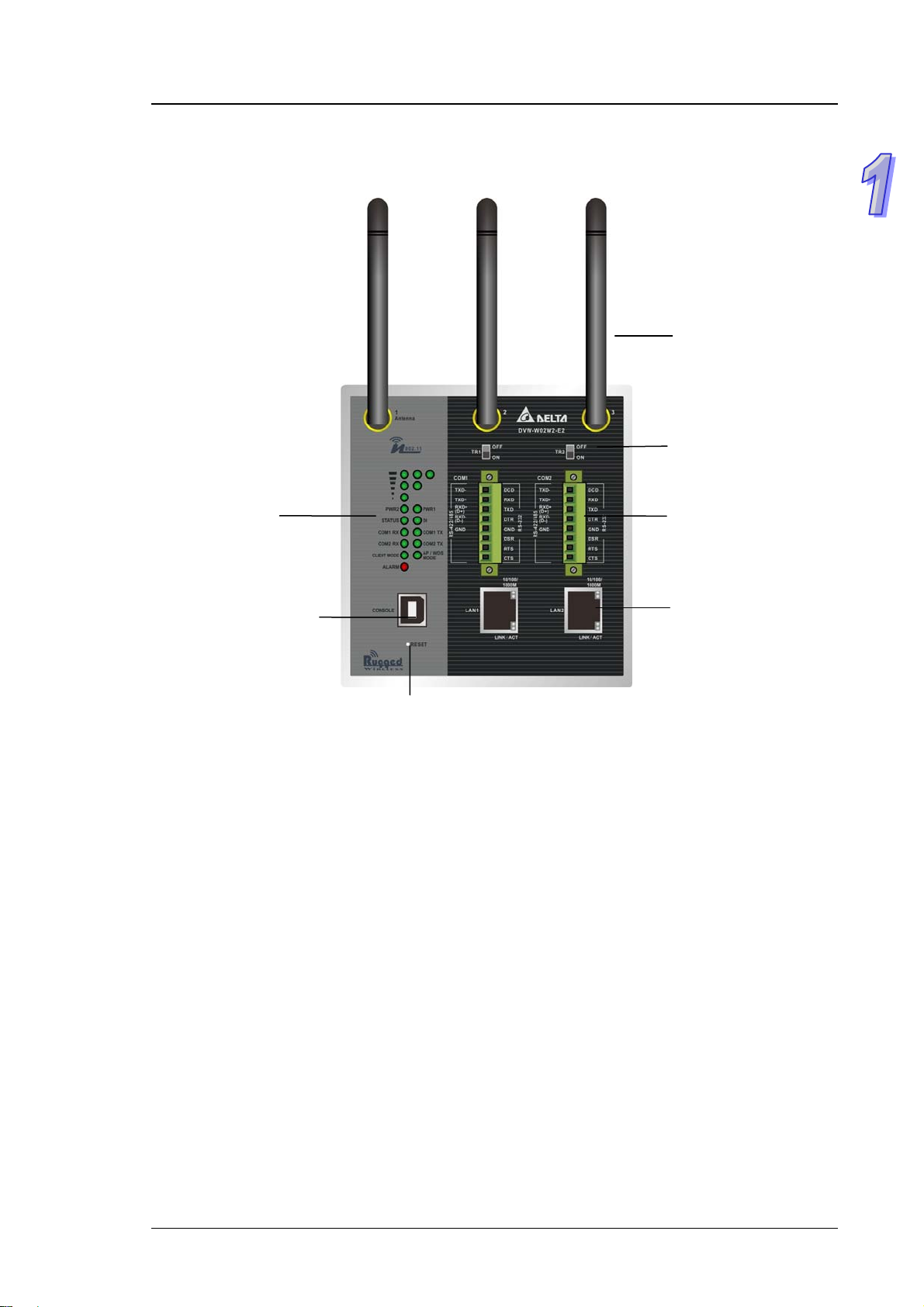
1.1.4 Front Panel Ports and LEDs
PWR LED
Status LED
DI LED
Chapter 1 Introduction
Terminal Resistor
COM TX/RX LED
USB Console Port
Reset Button
1-5
Page 12

DVW Series Industrial IEEE 802.11 a/b/g/n Wireless AP/WDS/Client/Gateway User Manual
1.1.5 Below Panel
DI
Port
DO
Port
Grounding
Screw
PWR Ports
1-6
Page 13

Chapter 1 Introduction
1.2 Antenna Installation
Please connect 3 antennas to the DVW device. You can adjust the direction or angle of the
antennas if the wireless signal is unstable.
1.2.1 Package Checklist
One Delta DVW Wireless AP/WDS/Client Gateway
Omni-directional Antenna x3
Wall mounting Plate x1
USB Type A to Type B console cable x1
User manual and software CD
Instruction Sheet
1-7
Page 14

DVW Series Industrial IEEE 802.11 a/b/g/n Wireless AP/WDS/Client/Gateway User Manual
MEMO
1-8
Page 15

Chapter 2 User Interface Introduction
Table of Contents
2.1 USB Console Configuration........................................................... 2-2
2.2 Telnet Console Configuration......................................................... 2-7
2.3 Web Browser Configuration........................................................... 2-8
2-1
Page 16

DVW Series Industrial IEEE 802.11 a/b/g/n Wireless AP/WDS/Client/Gateway User Manual
2.1 USB Console Configuration
Delta DVW devices supports configuration using CLI interface, it mainly includes six parts:
1. Exit (Exit this CLI session)
2. Maintenance (some utility commands for maintenance related details)
load_default
3. net
4. restart (restart the device)
5. system_info_setting (some utility commands for system information related details)
6. time_setting (some utility commands for time related details)
You can use terminal software to connect to Delta DVW devices. Before you use CLI interface,
please plug USB cable on USB port with baud rate 115200. The inactivity timeout value on a serial
port connection can be configured between 0 and 160 minutes. (Value 0: disable the timeout.)
work_setting (some utility commands for network details)
get_dns get_gateway get_ip_address
get_ip_configuration get_subnet_mask set_dns
set_gateway set_ip_address set_ip_configuration
set_subnet_mask view_setting
get_device_contact_info get_device_description get_device_location
get_device_name set_device_contact_info set_device_decription
set_device_location set_device_name view_setting
get_local_time get_timeserver1 get_timeserver2
get_timezone set_local_time set_timeserver1
set_timeserver2 set_timezone view_setting
2-2
Page 17

Chapter 2 User Interface Introduction
Below is an example to show you how to set the device name.
1. Open termina l software, and select an appropriate COM port for Console Connection, 115200
for Baud Rate, 8 for Data Bits, None for Parity, and 1 for Stop Bits, None for Flow Control.
2. T
ype clash and then press Enter.
2-3
Page 18

DVW Series Industrial IEEE 802.11 a/b/g/n Wireless AP/WDS/Client/Gateway User Manual
3. Type system_info_setting and then press Enter.
You can make full by use TAB to complete the command that you want to type.
PS.
4. Type set_device_name and the new device name, such as “test”, and then press Enter.
2-4
Page 19

Chapter 2 User Interface Introduction
5. The device name had changed to “test”, you can use “get_device_name” to see it.
6. T
ype exit to exit this CLI session.
2-5
Page 20

DVW Series Industrial IEEE 802.11 a/b/g/n Wireless AP/WDS/Client/Gateway User Manual
7. Sometimes if you don’t know how to u se the com mand (such as wha t does this co mmand mean ,
or how to set the parameter in right format, etc), you can type “?” to see the help information.
For example, if you want to set the local time to 2014/02/27 10:11:30, you may know type
time_setting and then type set_local_time, but the next? How should I input the time? You can
type ? to see the help information.
Complete command: “time_setting set_local_time ?” (After you click “?”, the help information
will display.)
8. Finally, you had got to know type 10:11:30 27 02 2014
2-6
Page 21

Chapter 2 User Interface Introduction
2.2 Telnet Console Configuration
Delta DVW device supports telnet server function; it can be globall y enabled or disabled. The user
can use all CLI command over a telnet session.
1. Open a Command Prompt and input “telnet 192.168.1.5” to login to Delta DVW device.
2. After input user name and password, you can use CLI command to control the device.
2-7
Page 22
DVW Series Industrial IEEE 802.11 a/b/g/n Wireless AP/WDS/Client/Gateway User Manual
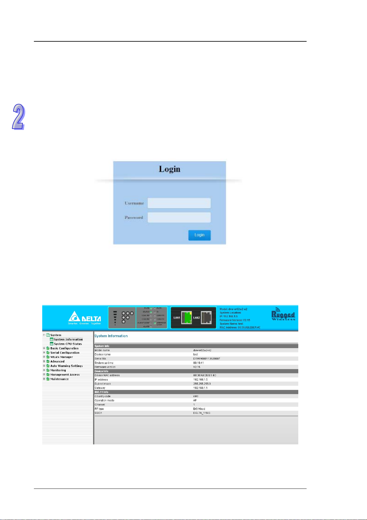
2.3 Web Browser Configuration
Delta DVW devices support a friendly web interface for normal u ser to configure the swit ch. You can
monitor the port status of Delta DVW device, and configure the settings of each function via web.
1.
Open a web browser and connect to 192.168.1.5 or http://www.deltawifi.net. Input user name
and password.
Username: admin
Password: password
2. You can use the menu tree in left side frame to find the function you want to configure. And
configure the detail settings in right side frame. The port status and LED status on the DVW
device can be monitored on the top frame.
2-8
Page 23

Chapter 3 Featured Functions
Table of Contents
3.1 System........................................................................................... 3-3
3.1.1 System Information........................................................................ 3-3
3.1.2 System CPU Status ....................................................................... 3-3
3.2 Basic Configuration........................................................................ 3-4
3.2.1 System Information Configuration.................................................. 3-4
3.2.2 Network Configuration................................................................... 3-4
3.2.3 Time Configuration ........................................................................ 3-7
3.2.3.1 Local Time Configuration........................................................... 3-7
3.2.3.2 NTP Server Configuration.......................................................... 3-8
3.3 Serial Configuration....................................................................... 3-8
3.3.1 Operation Configuration................................................................. 3-8
3.3.1.1 MODBUS ASCII/RTU Slave....................................................... 3-9
3.3.1.2 MODBUS ASCII/RTU Master....................................................3-11
3.3.1.3 TCP Server Mode .....................................................................3-13
3.3.1.4 TCP Client Mode.......................................................................3-16
3.3.1.5 Virtual COM Mode.....................................................................3-20
3.3.1.6 UDP Mode.................................................................................3-24
3.3.1.7 Pair Connection Mode...............................................................3-27
3.3.2 Port Configuration.........................................................................3-28
3.3.3 MODBUS Cache Table.................................................................3-29
3.4 WLAN Manager........................................................................... 3-32
3.4.1 Operation Mode............................................................................3-32
3.4.2 WLAN...........................................................................................3-35
3.4.2.1 Basic Wireless Configuration ....................................................3-35
3.4.2.2 Advanced Wireless Configuration.............................................3-43
3.5 Advanced..................................................................................... 3-45
3.5.1 VLAN Configuration......................................................................3-45
3.5.2 Packet Control..............................................................................3-46
3.5.3 Filter Configuration .......................................................................3-47
3.5.4 MAC Filters...................................................................................3-48
3.5.4.1 IP Protocol Filters......................................................................3-48
3.5.4.2 TCP/UDP Port Filters................................................................3-49
3.5.5 RSTP Configuration......................................................................3-50
3-1
Page 24

3.5.6 SNMP Configuration.....................................................................3-51
3.5.7 Storm Control...............................................................................3-53
3.6 Auto Warning Settings..................................................................3-53
3.6.1 SysLog .........................................................................................3-53
3.6.1.1 Syslog Event Types..................................................................3-54
3.6.1.2 Syslog Server Configuration.....................................................3-54
3.6.2 E-mail Alarm.................................................................................3-55
3.6.2.1 E-mail Event Types...................................................................3-55
3.6.2.2 E-mail Server Configuration......................................................3-56
3.6.3 Relay Alarm..................................................................................3-56
3.6.3.1 Relay Event Types....................................................................3-57
3.6.4 SNMP Trap...................................................................................3-57
3.6.4.1 Trap Event Types .....................................................................3-58
3.6.4.2 SNMP Trap Receiver Settings..................................................3-58
3.7 Monitoring Settings.......................................................................3-59
3.7.1 Email Alarm Table........................................................................3-59
3.7.2 Relay Alarm Table........................................................................3-59
3.7.3 Trap Alarm Table..........................................................................3-60
3.7.4 System Log ..................................................................................3-60
3.7.5 Network Connection Status..........................................................3-61
3.7.6 AP Client List................................................................................3-61
3.7.7 DHCP Client List ..........................................................................3-61
3.7.8 Serial Port State...........................................................................3-61
3.7.9 Serial Port Statistics.....................................................................3-62
3.7.10 Serial Port Error............................................................................3-62
3.7.11 Serial Port Log..............................................................................3-62
3.8 Management Access....................................................................3-62
3.8.1 SSH Configuration........................................................................3-63
3.8.2 Telnet Configuration.....................................................................3-63
3.9 Maintenance.................................................................................3-63
3.9.1 Password......................................................................................3-64
3.9.2 Ping..............................................................................................3-64
3.9.3 Firmware Upgrade........................................................................3-64
3.9.4 Log Export....................................................................................3-65
3.9.5 Config Import Export ....................................................................3-65
3.9.6 Reset to Default............................................................................3-65
3.9.7 Reboot..........................................................................................3-65
3.9.8 Logout ..........................................................................................3-66
3-2
Page 25

DVW Series Industrial IEEE 802.11 a/b/g/n Wireless AP/WDS/Client/Gateway User Manual
3.1 System
This group includes System Information and System CPU Status.
3.1.1 System Information
This page summarizes the current status of system. The information is categorized into several
groups: System Info, Device Info and 802.11 Info.
3.1.2 System CPU Status
This page summarizes the current status of CPU. It includes Running Time, Total Powered Time,
CPU Usage, RAM Total and RAM Available. These values should be grayed out and could not be
edited.
3-3
Page 26

Chapter 3 Featured Function
3.2 Basic Configuration
The basic configuration group includes most common settings, and administrator can maintain
control the DVW wireless devices in this group.
3.2.1 System Information Configuration
The System Information Configuration includes Device name, Device location, Device description
and Device contact information. By default, the Device name is DVW-W02W2-E2 and the Device
description is Series Industrial IEEE 802.11a/b/g/n wireless AP/bridge/client.
Item Description
Device name
Device location This field displays the location of the device.
Device description This field displays the description of the device.
Device contact information This field displays the contact information of the device.
This field displays the name of the device. The default value is
the model name.
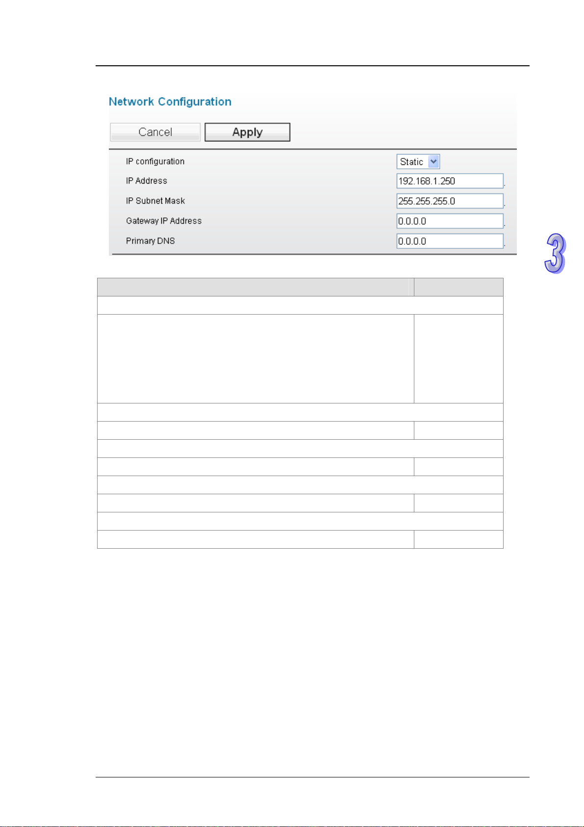
3.2.2 Network Configuration
The Network Settings includes IP configuration, IP address, IP Subnet Mask, Gateway IP
address and Primary DNS. Delta DVW device supports DHCP client and DHCP server function.
These two functions are enabled by default.
If the DVW device get an IP address by DHCP server or has been configured a static IP address,
the DHCP server function will be disabled. If the IP configuration is configured as DHCP, but it can’t
get IP address from DHCP server, then the IP address of the DVW device will be configured as
192.168.1.5, subnet mask as 255.255.255.0. And the DHCP server function will be enabled
automatically. DHCP server IP address pool is start from 192.168.1.128 to 192.168.1.200.
3-4
Page 27
DVW Series Industrial IEEE 802.11 a/b/g/n Wireless AP/WDS/Client/Gateway User Manual
Description Factory Default
IP Configuration
Specify the IP status of network interface.
Static: Specify the static IP address manually.
DHCP: The IP information of the switch is assigned from a
DHCP
Dynamic Host Configuration Protocol (DHCP) server on the
network.
IP Address
Input the IP address of the network interface. 192.168.1.5
IP Subnet Mask
Input the IP subnet mask of the network interface. 255.255.255.0
Gateway IP Address
Input the default gateway of the network interface. 0.0.0.0
Primary DNS
Input the primary DNS address of the network interface. 0.0.0.0
3-5
Page 28

Chapter 3 Featured Function
Notice:
The default network setting of DVW device is DHCP mode.
1. If there is a DHCP server in the network, than DVW device can get an IP
address, and the DHCP server function of DVW device will Disable
automatically. So when PC client or wireless client connects to DVW device and
send DHCP request to DVW device, it will forward the packet to DHCP serve r in
the network.
2. If user modifies the network setting of DVW device to Static mode, then DHCP
server function of DVW device will disable automatically. So when PC client or
wireless client connects to DVW device and send DHCP request to DVW device,
it will forward the packet to DHCP server in the network.
DHCP mode: Get an IP
address from DHCP server.
DHCP server of DVW: Disable
Static mode: Configure an IP
address manually.
3. If there is no DHCP server in the network, than DVW device can’t get any IP
address, and the DHCP server function of DVW device will Enable
automatically. So when PC client or wireless client connects to DVW device and
send DHCP request to DVW device, it will assign a n IP address to the clie nt. And
IP address of DVW device will be 192.168.1.5.
DHCP mode: Can’t get any IP
address from DHCP server.
DVW IP address: 192.168.1.5
DHCP server of DVW: Enable
3-6
Page 29

DVW Series Industrial IEEE 802.11 a/b/g/n Wireless AP/WDS/Client/Gateway User Manual
3.2.3 Time Configuration
3.2.3.1 Local Time Configuration
The local time can be set manually or get from NTP server dynamically. In order to get local time
dynamically, user should configure the time zone and time servers correctly. If it belongs to DST
area, please also enable “Automatically adjust for daylight savings time”.
The Current local time shows the DVW’s system time when you open thi s web p ag e. You can click
on the Set Time button to activate the updated date and time parameters.
Description Factory Default
Current local time
The date and time can be configured as local time. The 24-hour format:
YYYY/MM/DD HH:MM:SS
Time zone
The time zone setting can be configured as conversion from GMT
(Greenwich Mean Time) to local time.
Automatically adjust for daylight savings time
Daylight saving time (DST) also summer time is the practice of
advancing clocks during the lighter months so that ev enings have more
daylight and mornings have less.
None
Disable
3-7
Page 30

Description Factory Default
Time server 1/2
Specify the IP address or domain name of NTP time server. The
Chapter 3 Featured Function
second time server will be used if the first time server can’t be
connected.
None
3.2.3.2 NTP Server Configuration
When Delta DVW device get valid local time, DVW device can enable NTP Server to supply the time
service for LAN clients.
Description Factory Default
NTP server
Specify whether the NTP server is enabled.
Enable: The NTP server function is enabled.
Disable: The NTP server function is disabled.
NTP server 1/2
Specify the IP address or domain name of NTP server of DVW device.
The second NTP server will be used if the first NTP server can’t be
connected.
Disable
www.deltawifi.com
www.deltawifi.net
3.3 Serial Configuration
DVW provides 2 kinds of serial function, MODBUS Gateway function and Serial Server function.
MODBUS Gateway function can convert data from MODBUS to Ethernet or from Ethernet to
MODBUS. Serial Server includes different modes for different interaction in the network.
3.3.1 Operation Configuration
If your have requirement about MODBUS Gateway function, DVW device provides MODBUS
ASCII/RTU Slave mode and MODBUS ASCII/RTU Master mode. If you have requirement about
Serial Server function, DVW device provides TCP Server mode, TCP Client mode, Virtual COM
mode, UDP mode, Pair Connection mode – Master and Pair Connection mode – Slave.
3-8
Page 31

DVW Series Industrial IEEE 802.11 a/b/g/n Wireless AP/WDS/Client/Gateway User Manual
3.3.1.1 MODBUS ASCII/RTU Slave
When a MODBUS master device send a request message to MODBUS slave device, the MODBUS
slave device will forward the message according to the slave ID. If the same slave ID is being used
in serial network, then the communication will have problem.
Slave ID Map function can help you to create a map ID for the devices which has the same real
Station ID. You can specify the range of map ID on each serial port, and then DVW device will
forward the message to the serial device according to the map ID table.
3-9
Page 32

Chapter 3 Featured Function
Description Factory Default
Operation Mode
Display the operation mode of serial port. Fixed
Station ID
Port 1: 246
Specify the station ID of the device.
Port 2: 247
TCP Alive Time
Specify how long the DVW device keeps the TCP session when there
is no TCP activity in specified time. If the time is “0”, then the
30
connection will remain open.
Response Timeout
Specify how long the DVW device waits the response from the serial
3000
device.
Retry
Specify the retry time when the time of Response Timeout reached. 3
3-10
Page 33

DVW Series Industrial IEEE 802.11 a/b/g/n Wireless AP/WDS/Client/Gateway User Manual
Description Factory Default
MODBUS Exception
Specify whether the device send an exception code back to the client
Enable
when the response timeout is reached.
Slave ID Map
Specify the mapping t able of slave ID.
Slave ID Range: Enter the range of real slave ID.
None
Map ID Range: Enter the range of virtual slave ID which DVW device
can create.
Priority
Specify the priority of the serial device. None
3.3.1.2 MODBUS ASCII/RTU Master
If the serial device that connect to DVW device has Ethernet interface, you can specify the station
address and destination IP address in forward table. DVW device follows the forward table to
forward data to correct serial devices.
3-11
Page 34

Chapter 3 Featured Function
Description Factory Default
Operation Mode
Display the operation mode of serial port. Fixed
Station ID
Port 1: 246
Specify the station ID of the device.
Port 2: 247
TCP Alive Time
Specify how long the DVW device keeps the TCP session when there
is no TCP activity in specified time. If the time is “0”, then the
30
connection will remain open.
Response Timeout
Specify how long the DVW device waits the response from the serial
3000
device.
Retry
Specify the retry time when the time of Response Timeout reached. 3
3-12
Page 35

DVW Series Industrial IEEE 802.11 a/b/g/n Wireless AP/WDS/Client/Gateway User Manual
Description Factory Default
MODBUS Exception
Specify whether the device send an exception code back to the client
Enable
when the response timeout is reached.
Forward Table
Description Factory Default
Enable
Specify whether the forward information is enabled. Uncheck
Local Port
The local port of DVW device will create automatically.
8000~8031
Port 1: 8000~8031
9000~9031
Port 2: 9000~9031
Station Address
Specify the station ID of serial devices. None
Destination IP Address
Specify the IP address of serial devices. None
3.3.1.3 TCP Server Mode
In TCP Server Mode, DVW device works as a passive role. DVW device waits the connected
requirement from the host computer or device. The host must send a request message to DVW
device for establish the connection first. After the connection is established, the data can be
transmitted between the host and DVW device.
3-13
Page 36

Chapter 3 Featured Function
Description Factory Default
Operation Mode
Display the operation mode of serial port. Fixed
Alive Check Time
Specify how long the DVW device sends a packet for checking the
30
connection still alive.
Disconnect Time
Specify how long the DVW device keeps the TCP session when there
is no TCP activity in specified time. If the time is “0”, then the
3000
connection will remain open.
TCP Port
Specify the port number of DVW device. 3000
3-14
Page 37

DVW Series Industrial IEEE 802.11 a/b/g/n Wireless AP/WDS/Client/Gateway User Manual
Data Packing
Description Factory Default
Fixed Length
Specify whether sends the packet with fixed length. When the receiving
data length matches with the configured value, the data will be sent.
Notice:
Before you enter the value of fixed length, please remember
Disable/
1024
check the Enable item, otherwise the Fixed Length function
doesn’t work.
Prefix
Specify the Prefix Length and Prefix Process of data.
Notice:
Before you configure the settings of Prefix Length, Prefix
Disable
Char and Prefix Process, please remember check the Enable
item, otherwise the Prefix function doesn’t work.
Prefix Length
Specify the Prefix Length for comparison process. After specify the
2
Prefix Length, please enter the Prefix Char for process.
Prefix Char (Hex.)
Enter the Prefix Char for comparison process. 0xFF, 0xFF
Prefix Process
Specify the compa rison process for the Prefix Length and Prefix Char.
Include Prefix Char: The data will transmit all the Prefix Char
which user entered in Prefix Char (Hex.). If the Prefix Length is 1,
then only first Char will be included.
Only Prefix Char 2: The data will transmit only Prefix Char 2
which user entered in Prefix Char (Hex.).
Not Include: After the comparison process is complete, the data
will be transmitted without Prefix Char which the user entered in
Prefix Char (Hex.).
Suffix
Specify the Suffix Length and Suffix Process of data.
Notice:
Before you configure the settings of Suffix Length, Suffix Char
and Suffix Process, please remember check the Enable item,
otherwise the Suffix function doesn’t work.
Include Prefix
Char
Disable
3-15
Page 38

Suffix Length
Chapter 3 Featured Function
Description Factory Default
Specify the Suffix Length for comparison process. After specify the
2
Suffix Length, please enter the Suffix Char for process.
Suffix Char (Hex.)
Enter the Suffix Char for comparison process. 0xFF, 0xFF
Suffix Process
Specify the comparison process for the Suffix Length and Suffix Char.
Include Suffix Char: The data will transmit all the Suf f ix Char
which user entered in Suffix Char (Hex.). If the Suffix Length is 1,
then only first Suffix Char will be included.
Include Suffix
Only Suffix Char 1: The data will transmit only Suffix Char 1
Char
which user entered in Suffix Char (Hex.).
Not Include: After the comparison process is complete, the data
will be transmitted without Suffix Char which the user entered in
Suffix Char (Hex.).
Aging Time
Specify the time for DVW device to force pack the received serial data
into the same data frame.
Notice:
Before you configure the settings of Aging Time, please
Disable/
1000 (ms)
remember check the Enable item, otherwise the Aging Time
doesn’t be applied.
3.3.1.4 TCP Client Mode
In TCP Client Mode, DVW device works as an active role. User can enter the destination IP
information of the host computer or device in Destination IP Table first. Then DVW device sends a
request message to the host for establish the connection first. After the connection is established,
the data can be transmitted between the host and DVW device.
3-16
Page 39

DVW Series Industrial IEEE 802.11 a/b/g/n Wireless AP/WDS/Client/Gateway User Manual
Description Factory Default
Operation Mode
Display the operation mode of serial port. Fixed
Alive Check Time
Specify how long the DVW device sends a packet for checking the
30
connection still alive.
Disconnect Time
Specify how long the DVW device keeps the TCP session when there
is no TCP activity in specified time. If the time is “0”, then the
3000
connection will remain open.
Destination IP Table
Description Factory Default
Enable
Specify whether the destination IP information is enabled. Uncheck
3-17
Page 40

Local Port
Chapter 3 Featured Function
Description Factory Default
Specify the local listen port of DVW device for the specified destination
None
device which uses to establish the connection.
Destination IP Address
Specify the IP address of the Ethernet device. None
Remote Port
Specify the port number of the Ethernet device. None
Data Packing
Description Factory Default
Fixed Length
Specify whether sends the packet with fixed length. When the receiving
data length matches with the configured value, the data will be sent.
Notice:
Before you enter the value of fixed length, please remember
check the Enable item, otherwise the Fixed Length function
doesn’t work.
3-18
Disable/
1024
Page 41

DVW Series Industrial IEEE 802.11 a/b/g/n Wireless AP/WDS/Client/Gateway User Manual
Description Factory Default
Prefix
Specify the Prefix Length and Prefix Process of data.
Notice:
Before you configure the settings of Prefix Length, Prefix
Disable
Char and Prefix Process, please remember check the Enable
item, otherwise the Prefix function doesn’t work.
Prefix Length
Specify the Prefix Length for comparison process. After specify the
2
Prefix Length, please enter the Prefix Char for process.
Prefix Char (Hex.)
Enter the Prefix Char for comparison process. 0xFF, 0xFF
Prefix Process
Specify the compa rison process for the Prefix Length and Prefix Char.
Include Prefix Char: The data will transmit all the Prefix Char
which user entered in Prefix Char (Hex.). If the Prefix Length is 1,
then only first Char will be included.
Include Prefix
Only Prefix Char 2: The data will transmit only Prefix Char 2
Char
which user entered in Prefix Char (Hex.).
Not Include: After the comparison process is complete, the data
will be transmitted without Prefix Char which the user entered in
Prefix Char (Hex.).
Suffix
Specify the Suffix Length and Suffix Process of data.
Notice:
Before you configure the settings of Suffix Length, Suffix Char
Disable
and Suffix Process, please remember check the Enable item,
otherwise the Suffix function doesn’t work.
Suffix Length
Specify the Suffix Length for comparison process. After specify the
2
Suffix Length, please enter the Suffix Char for process.
Suffix Char (Hex.)
Enter the Suffix Char for comparison process. 0xFF, 0xFF
3-19
Page 42

Description Factory Default
Suffix Process
Specify the comparison process for the Suffix Length and Suffix Char.
Include Suffix Char: The data will transmit all the Suf f ix Char
which user entered in Suffix Char (Hex.). If the Suffix Length is 1,
Chapter 3 Featured Function
then only first Suffix Char will be included.
Include Suffix
Only Suffix Char 1: The data will transmit only Suffix Char 1
Char
which user entered in Suffix Char (Hex.).
Not Include: After the comparison process is complete, the data
will be transmitted without Suffix Char which the user entered in
Suffix Char (Hex.).
Aging Time
Specify the time for DVW device to force pack the received serial data
into the same data frame.
Notice:
Before you configure the settings of Aging Time, please
Disable/
1000 (ms)
remember check the Enable item, otherwise the Aging Time
doesn’t be applied.
3.3.1.5 Virtual COM Mode
In Virtual COM mode, DVW device can establish a network connection between the host computer
and serial device. So the DVW device maps the IP address with port number to the serial port on
itself. When the application on host computer doesn’t provide serial interface to connect with serial
device, then Virtual COM mode can solve this problem and establish a Virtual COM connection on
Ethernet interface.
3-20
Page 43

DVW Series Industrial IEEE 802.11 a/b/g/n Wireless AP/WDS/Client/Gateway User Manual
Description Factory Default
Operation Mode
Display the operation mode of serial port. Fixed
Alive Check Time
Specify how long the DVW device sends a packet for checking the
connection still alive.
Disconnect Time
Specify how long the DVW device keeps the TCP session when there
is no TCP activity in specified time. If the time is “0”, then the
3000
connection will remain open.
TCP Port
Specify the port number of DVW device. 3000
30
3-21
Page 44

Data Packing
Description Factory Default
Fixed Length
Specify whether sends the packet with fixed length. When the receiving
data length matches with the configured value, the data will be sent.
Chapter 3 Featured Function
Notice:
Before you enter the value of fixed length, please remember
Disable/
1024
check the Enable item, otherwise the Fixed Length function
doesn’t work.
Prefix
Specify the Prefix Length and Prefix Process of data.
Notice:
Before you configure the settings of Prefix Length, Prefix
Disable
Char and Prefix Process, please remember check the Enable
item, otherwise the Prefix function doesn’t work.
Prefix Length
Specify the Prefix Length for comparison process. After specify the
2
Prefix Length, please enter the Prefix Char for process.
Prefix Char (Hex.)
Enter the Prefix Char for comparison process. 0xFF, 0xFF
Prefix Process
Specify the compa rison process for the Prefix Length and Prefix Char.
Include Prefix Char: The data will transmit all the Prefix Char
which user entered in Prefix Char (Hex.). If the Prefix Length is 1,
then only first Char will be included.
Only Prefix Char 2: The data will transmit only Prefix Char 2
which user entered in Prefix Char (Hex.).
Not Include: After the comparison process is complete, the data
will be transmitted without Prefix Char which the user entered in
Prefix Char (Hex.).
Include Prefix
Char
3-22
Page 45

DVW Series Industrial IEEE 802.11 a/b/g/n Wireless AP/WDS/Client/Gateway User Manual
Description Factory Default
Suffix
Specify the Suffix Length and Suffix Process of data.
Notice:
Before you configure the settings of Suffix Length, Suffix Char
Disable
and Suffix Process, please remember check the Enable item,
otherwise the Suffix function doesn’t work.
Suffix Length
Specify the Suffix Length for comparison process. After specify the
2
Suffix Length, please enter the Suffix Char for process.
Suffix Char (Hex.)
Enter the Suffix Char for comparison process. 0xFF, 0xFF
Suffix Process
Specify the comparison process for the Suffix Length and Suffix Char.
Include Suffix Char: The data will transmit all the Suf f ix Char
which user entered in Suffix Char (Hex.). If the Suffix Length is 1,
then only first Suffix Char will be included.
Include Suffix
Only Suffix Char 1: The data will transmit only Suffix Char 1
Char
which user entered in Suffix Char (Hex.).
Not Include: After the comparison process is complete, the data
will be transmitted without Suffix Char which the user entered in
Suffix Char (Hex.).
Aging Time
Specify the time for DVW device to force pack the received serial data
into the same data frame.
Notice:
Before you configure the settings of Aging Time, please
remember check the Enable item, otherwise the Aging Time
doesn’t be applied.
Disable/
1000 (ms)
3-23
Page 46

Chapter 3 Featured Function
3.3.1.6 UDP Mode
Compare with TCP communication, UDP communication doesn’t need request message before the
session has been established. So after user configure the remote IP addre s s and port information,
the device will start to transmit the data. You can use unicast or multicast way to transmit data
between the host computer and serial device.
Forward Table
Description Factory Default
Enable
Specify whether the forward information is enabled. Uncheck
Local Port
Specify the local listen port of DVW device for the device which uses to
None
establish the connection.
Begin IP Address
Specify the beginning of destination IP address. None
End IP Address
Specify the end of destination IP address. None
Remote Port
Specify the port number of the Ethernet device. None
3-24
Page 47

DVW Series Industrial IEEE 802.11 a/b/g/n Wireless AP/WDS/Client/Gateway User Manual
Data Packin
g
Description Factory Default
Fixed Length
Specify whether sends the packet with fixed length. When the receiving
data length matches with the configured value, the data will be sent.
Notice:
Before you enter the value of fixed length, please remember
check the Enable item, otherwise the Fixed Length function
doesn’t work.
Prefix
Specify the Prefix Length and Prefix Process of data.
Notice:
Before you configure the settings of Prefix Length, Prefix
Char and Prefix Process, please remember check the Enable
Disable/
1024
Disable
item, otherwise the Prefix function doesn’t work.
Prefix Length
Specify the Prefix Length for comparison process. After specify the
Prefix Length, please enter the Prefix Char for process.
2
3-25
Page 48

Chapter 3 Featured Function
Description Factory Default
Prefix Char (Hex.)
Enter the Prefix Char for comparison process. 0xFF, 0xFF
Prefix Process
Specify the compa rison process for the Prefix Length and Prefix Char.
Include Prefix Char: The data will transmit all the Prefix Char
which user entered in Prefix Char (Hex.). If the Prefix Length is 1,
then only first Char will be included.
Only Prefix Char 2: The data will transmit only Prefix Char 2
which user entered in Prefix Char (Hex.).
Not Include: After the comparison process is complete, the data
will be transmitted without Prefix Char which the user entered in
Prefix Char (Hex.).
Suffix
Specify the Suffix Length and Suffix Process of data.
Notice:
Before you configure the settings of Suffix Length, Suffix Char
and Suffix Process, please remember check the Enable item,
otherwise the Suffix function doesn’t work.
Suffix Length
Specify the Suffix Length for comparison process. After specify the
Suffix Length, please enter the Suffix Char for process.
Suffix Char (Hex.)
Include Prefix
Char
Disable
2
Enter the Suffix Char for comparison process. 0xFF, 0xFF
Suffix Process
Specify the comparison process for the Suffix Length and Suffix Char.
Include Suffix Char: The data will transmit all the Suf f ix Char
which user entered in Suffix Char (Hex.). If the Suffix Length is 1,
then only first Suffix Char will be included.
Include Suffix
Only Suffix Char 1: The data will transmit only Suffix Char 1
Char
which user entered in Suffix Char (Hex.).
Not Include: After the comparison process is complete, the data
will be transmitted without Suffix Char which the user entered in
Suffix Char (Hex.).
3-26
Page 49

DVW Series Industrial IEEE 802.11 a/b/g/n Wireless AP/WDS/Client/Gateway User Manual
Description Factory Default
Aging Time
Specify the time for DVW device to force pack the received serial data
into the same data frame.
Notice:
Before you configure the settings of Aging Time, please
Disable/
1000 (ms)
remember check the Enable item, otherwise the Aging Time
doesn’t be applied.
3.3.1.7 Pair Connection Mode
Pair Connection Master and Slave modes connect two DVW devices over a network. The serial
device can connect to a DVW device, and two DVW can use wired Ethernet cable or wireless way to
connect each other. Then two serial devices can overcome the distance limitatio n of serial inte rface.
Pair Connection Master Mode
Description Factory Default
Operation Mode
Display the operation mode of serial port. Fixed
Alive Check Time
Specify how long the DVW device sends a packet for checking the
30
connection still alive.
Destination IP
Specify the IP address for the destination DVW device with Pair
None
Connection Slave mode.
3-27
Page 50

Destination Port
Chapter 3 Featured Function
Description Factory Default
Specify the port number for the destination DVW device with Pair
Connection Slave mode.
Pair Connection Slave Mode
Description Factory Default
Alive Check Time
Specify how long the DVW device keeps the connection. If the time is
“0”, then the connection will remain open.
TCP Port
Specify the port number for the DVW device with Pair Connection
Master mode to connect.
None
30
None
3.3.2 Port Configuration
You can view the current communication settings for each serial port in this page. If you need to
configure the settings,
3-28
Page 51

DVW Series Industrial IEEE 802.11 a/b/g/n Wireless AP/WDS/Client/Gateway User Manual
Parameter Value
Interface
Data bit
Parity bit
Stop bit
Baud rate
Flow Control
Buffer Size
RS232, RS485, RS422
7, 8
None, Even, Odd, Space, Mark
1, 2
110 to 921600 bps
None, RTS/CTS, XON/XOFF
10 (Default Value)
3.3.3 MODBUS Cache Table
The transmit speed of Ethernet interface is faster than serial interface, so the device on Ethernet
side usually need to spend much time to wait the data from serial side after they send the request
message to the device on serial side. MODBUS Cache Table provide user for configure the device
information (ex. Station ID, MODBUS address…etc.), and DVW can send request messa ge for get
the data from the device on serial side according to the MODBUS Cache table in advance. When
the device on Ethernet side sends the request to DVW device, then DVW can response the data
immediately. Because DVW device don’t need to forward the request message to the device on
serial side again, it already get the data in advance. So this only can be enabled when the ope ration
mode in MODBUS Slave mode.
3-29
Page 52

Chapter 3 Featured Function
Read data in MODBUS Cache mode
d data in Non MODBUS Cache Table mode
Rea
Description Factory Default
Enable
Specify whether the MODBUS Cache function is enabled. Un check
Cycle time
Specify the time of sending request message with serial devices. 10
3-30
Page 53

DVW Series Industrial IEEE 802.11 a/b/g/n Wireless AP/WDS/Client/Gateway User Manual
Description Factory Default
Available size
Display the remaining size for the data can be monitored. 1MB size
can include 100,000 data.
Timeout Calibration
Display the adjusted time of Response Timeout. When user click the
Detect button, DVW device will communicate with the device
according to the MODBUS Cache table
Coil Device
Item Description
Station Addre ss The station ID of the device.
MODBUS (Hex.) The MODBUS address in hexadecimal.
MODBUS (Dec.) The MODBUS address in decimal.
State The value of the MODBUS address.
Word Device
Item Description
Fixed
Fixed
Station Addre ss The station ID of the device.
MODBUS (Hex.) The MODBUS address in hexadecimal.
MODBUS (Dec.) The MODBUS address in decimal.
Present Value The present value of the MODBUS address.
Format The format of the value as Hex or Dec.
3-31
Page 54

Chapter 3 Featured Function
Description Factory Default
Station Address
The station ID of the device. None
MODBUS (Hex.)
The MODBUS address in hexadecimal. None
MODBUS (Dec.)
The MODBUS address in decimal. None
Account
The amount of MODBUS data can be monitored. None
Format
Specify the format of the value as Hex or Dec. Hex
Online
Specify whether the data display in MODBUS monitored table. Uncheck
3.4 WLAN Manager
The device should support AP mode, Client mode, Repeater mode and WDS (Master/Slave) mode.
3.4.1 Operation Mode
Delta DVW device provides 5 operation modes for you to configure in different network environment.
Before you establish your wireless network, you must specify an operation mode on DVW device.
AP Mode
When DVW device configures as AP (Access Point) mode, it can provide the connectivity for
wireless client.
3-32
Page 55

DVW Series Industrial IEEE 802.11 a/b/g/n Wireless AP/WDS/Client/Gateway User Manual
Client Mode
When DVW device configures as Client mode, it can provides LAN-to-WLAN connection type. If a
client doesn’t equipped wireless card, it can use Ethernet cable connect to DVW device which be
configured as Client mode, and have a connection with another AP.
Repe
ater Mode
When DVW device configures as Repeater mode, it can extend the wireless distance between two
wireless devices. It supports AP mode and Client mode concurrently. You can set more than one
repeater between two wireless devices, but it will affect the throughput.
WDS Master and Slave Mode
When the DVW device configures as WDS Master mode, it will be enabled as a Base Station. User
can add the MAC address of the repeaters. Up to 4 repeaters can be added.
When the DVW device configures as WDS Slave mode, it will be enabled as a Repeater. User can
add the MAC address of the base station.
3-33
Page 56

Chapter 3 Featured Function
Description Factory Default
Wireless enable
Specify whether the wi reless is enabled or not.
Enable: Wireless function can work.
Disable: Wireless function can’t work.
3-34
Disable
Page 57

DVW Series Industrial IEEE 802.11 a/b/g/n Wireless AP/WDS/Client/Gateway User Manual
Description Factory Default
Operation mode
Specify the wireless operation mode:
AP: Specify DVW device work as AP mode.
Client: Specify DVW device work as Client mode.
Repeater: Specify DVW d evice work as Repeater mode.
Master: Specify DVW device work as a WDS Master mode.
Slave: Specify DVW device work as a WDS Slave mode.
Region
Specify the country where the device locates. None
Notice:
If you click Cancel button, GUI will revoke all your input and revoke to previous
settings, then return to “Basic Wireless Configuration” page.
AP
3.4.2 WLAN
3.4.2.1 Basic Wireless Configuration
After you specify the Operation Mode, please add a SSID in Basic Wireless Configuration page.
And click Edit button to configure the wireless settings.
Notice:
Please remember to click Apply button after you add a SSID setting, otherwise the
SSID setting will not be enabled.
3-35
Page 58

Chapter 3 Featured Function
Description Factory Default
Operation Mode
Display the current operation mode. Fixed
RF Type
2.4GHz
B: 802.11B only mode
G: 802.11G only mode
B/G Mixed: Support 802.11B and 802.11G mode
G/N Mixed: Support 802.11G and 802.11N mode, Not support
802.11B
B/G Mixed
B/G/N Mixed: Support 802.11B/G/N mode
N Only (2.4GHz): Only support 802.11N mode
5GHz
A : 802.11A only mode
A/N Mixed: Support 802.11A and 802.11NA mode
N Only (5GHz): Support 802.11N Only
3-36
Page 59

DVW Series Industrial IEEE 802.11 a/b/g/n Wireless AP/WDS/Client/Gateway User Manual
Description Factory Default
Channel
2.4GHz
NA: 11
Europe: 1~13
Japan: 1~13
5GHz
Japan: 36, 40, 44, 48, 52
Europe: 36, 40, 44, 48
USA: 36, 40, 44, 48, 149, 153, 157, 161,165
SSID
Specify the name of wireless device. It is case sensitive. You can input
1 to 32 characters for SSID and space is allowed.
SSID broadcast
Specify whether the SSID broadcast is enabled.
Enable: SSID can be broadcast.
Disable: SSID can’t be broadcast.
Security mode
Please refer to Wireless Security Settings section.
Notice:
If the operation mode is Client mode or Repeater mode, the Site Survey button will
1
DELTA_11NG
Enable
None
display in Basic Wireless Configuration page. After click “Site Survey” button, the
available APs will displays as below figure. Click one SSID to connect, and brings the
value of SSID and security type into Basic Wireless Configuration page.
3-37
Page 60

Chapter 3 Featured Function
If you specify the Operation Mode to WDS Master mode, you can input the MAC address of
repeater which allows associating with each other in this page.
Description Factory Default
Enable Wireless Repeating Function
Specify whether the wireless repeating function is enabled or not. Disable
Wireless MAC of this device
Display the wireless MAC address of DVW device. MAC address
Disable Wireless Client Association
Specify whether the wi reless client can associate with DVW device or
Disable
not.
Repeater MAC Address
Enter the MAC address of repeaters. Maximum is 4 repeaters. None
If you specify the Operation Mode to WDS Slave mode, you can input one MAC address of base
station which allows associating with each other in this page.
3-38
Page 61

DVW Series Industrial IEEE 802.11 a/b/g/n Wireless AP/WDS/Client/Gateway User Manual
Description Factory Default
Enable Wireless Repeating Function
Specify whether the wireless repeating function is enabled or not. Disable
Wireless MAC of this device
Display the wireless MAC address of DVW device. MAC address
Repeater IP Address
Specify an new repeater (WDS Slave) IP address to avoid the
None
confliction with base station (WDS Master)
Disable Wireless Client Association
Specify whether the wi reless client can associate with DVW device or
Disable
not.
Base Station MAC Address
Enter the MAC address of base station. None
Notice:
WDS mode only supports None and WEP security mode.
Wireless Security Settings
DVW device provides four standard security modes: None, WEP, WPA, and WPA2. You also can
specify personal or enterprise version of WPA/WPA2 according to your requirement.
None
Any client can connect to DVW device without any security if you don’t specify wireless security on
DVW. So we suggest you do not set security mode to None security.
WEP
WEP security doesn’t display from 11N mode and any future higher rate wireless mode. It only
displays in 11b only, 11 b/g, 11 g only and 11a wireless mode. If you selects WEP in the web GUI,
only (legacy 802.11 b/g or legacy 802.11 a) can be displayed in the wireless mode list.
3-39
Page 62

Description Factory Default
Authentication Type
Automatic: Specify the authentication type as Automatic, so the
Chapter 3 Featured Function
wireless client can use no matter “open system” or “shared key” to
Automatic
pass the authentication.
Shared key: Specify the authentication type as Shared key.
Encryption Strength
64-bit: Allows enter 10 hexadecimals value.
64-bit
128-bit: Allows enter 26 hexadecimals value.
Security Encryption (WEP) Key
Specify the client key ID. The client key ID must match with the key ID
None
on AP or extender side, otherwise the data packet can’t be decrypted.
WPA/WPA2 Personal
Wi-Fi Protected Access (WPA) and Wi-Fi Protected Acce ss 2 (WPA2) are two security protocols and
security certification programs developed by the Wi-Fi Alliance to secure wireless computer
networks. Personal versions of WPA/WPA2, also know as WPA/WPA-PSK (Pre-Shared Key)
TKIP (Temporal Key Integrity Protocol) and AES (Advance Encryption System) are two encryption
methods. TKIP can automatically producing a new network key every few minutes. This prevents
attackers from ever gathering enough data to break into your network. AES stands for advanced
encryption standard. This data encryption system, which is either a 128-bit, 192-bit or 256-bit cipher
block, is considered by experts to be the most secure encryption protection option for your wireless
network.
If you select WPA-PSK (TKIP) security on DVW device, then it doesn’t display from 11N mode and
any future higher rate wireless mode. It only displays in 11b only, 11 b/g, 11g only and 11a wireless
mode. If you select WPA-PSK (TKIP) in the web GUI, only legacy 802.11 b/g or legacy 802.11a can
be displayed in the wireless mode list.
3-40
Page 63

DVW Series Industrial IEEE 802.11 a/b/g/n Wireless AP/WDS/Client/Gateway User Manual
Description Factory Default
Security Options
WPA-PSK: TKIP encryption method is enabled.
WPA2-PSK: AES encryption method is enabled.
WPA-PSK+WPA2-PSK: This setting supports both WPA-PSK
Fixed
and WPA2-PSK. Broadcast packets use TKIP. For unicast
(point-to-point) transmissions, WPA-PSK clients use TKIP, and
WPA2-PSK clients use AES.
Passphrase
The passphrase requires 8 to 63 ASCII characters or 64 hex digits.
None
WPA/WPA2 Enterprise (For AP/Master mode)
Enterprise security mode provides the security needed for wireless networks in business
environments. If you select this security mode, there must have a RADIUS serv er in yo ur network. It
offers individualized and centralized control over access to your Wi-Fi network.
If the wireless client wants to access the network resource, it will send the request to DVW device.
And DVW device will forward the request to RADIUS server and forward the response to wireless
client. If the wireless client passes the authentication of RADIUS, then it can access the network
resource; otherwise it can’t access the network resource.
3-41
Page 64

Description Factory Default
WPA Mode
WPA [TKIP]: TKIP encryption method is enabled.
Chapter 3 Featured Function
WPA2 [AES]: AES encryption method is enabled.
WPA [TKIP]+WPA2 [AES]: This setting supports both WPA (with
TKIP) and WPA2 (AES). You have to use TKIP+AES encryption
and configure the RADIUS server settings.
RADIUS server IP Address
Specify the RADIUS server IP address. None
RADIUS server Port
Specify the port number of the RADIUS server. 1812
RADIUS server Shared Secret
Specify the shared secret between the wireless AP and the RADIUS
server when the supplicant (wireless client) is authenticated.
WPA [TKIP] +
WPA2 [AES]
None
3-42
Page 65

DVW Series Industrial IEEE 802.11 a/b/g/n Wireless AP/WDS/Client/Gateway User Manual
3.4.2.2 Advanced Wireless Configuration
There are some advanced wireless parameters which can be configured in this page.
Description Factory Default
CTS/RTS Threshold
Specify the threshold p acket size of CTS (Clear to Send) and RTS
2347
(Request to Send).
Fragmentation Length
Specify the maximum packet size. Packets larger than the size
programmed in this field will be fragmented. The Fragment Threshold
2346
value must be larger than the RTS Threshold value.
Beacon Interval
Specify the frequency interval of the beacon. 100 (ms)
Aggregation Length
Specify aggregation length of the frame. It can increases throu ghput by
1024
sending two or more data frames in a single transmission.
AMPDU
Specify whether AMPDU (Aggregated-MAC Packet Data Unit) allows
Disable
to build a group of frame before transmit frame.
DTIM Interval
Specify how often the DVW device sends out a Delivery Traffic
Indication Message.
1
3-43
Page 66

Description Factory Default
Preamble Mode
Specify the preamble mode:
Automatic: Automatically handle both long and short preamble.
Chapter 3 Featured Function
Short Preamble: Provide better performance.
Long Preamble: Provide more reliable connection or slightly
longer range.
Notice:
These parameters are reserved for wireless testing and advan ced configuration
only. If you don’t know how to configure, please do not change these settings.
Automatic
3-44
Page 67

DVW Series Industrial IEEE 802.11 a/b/g/n Wireless AP/WDS/Client/Gateway User Manual
3.5 Advanced
3.5.1 VLAN Configuration
Virtual LAN (VLAN) is a logically group network. DVW provide VLAN function base on SSID. Each
SSID can be configured one VLAN ID. DVW can support up to 8 SSIDs.
Whe
n DVW transmit or receive packets, it matches the SSID and VLAN ID. So that only members of
the VLAN could receive packets from the same VLAN ID members. And VLAN also allow user to
access the network from a different place or network devices. So it provides security and flexibility.
And it also avoids unnecessary traffic on wireless LAN and maximizing throughp ut.
For example: Configure department A, B, C to VLAN 1, 2, 3. User only can access the resource
which belongs to their department, so the resource in their department can be protected. And they
can access the resource in a different floor, even though in a different place. So they don’t need to
stay in a fixed place to access the resource which belongs to their dep artment.
3-45
Page 68

Chapter 3 Featured Function
Description Factory Default
Management VLAN ID
Specify the management VLAN ID. 1
Port
LAN: Display the LAN port number.
WLAN: The wireless port for the specific SSID. The number of
wireless port depends on how many SSIDs you created.
PVID
Specify the port’ s VLAN ID. PVID is set for the device which connect
with this port
WLAN Tagged
Specify which VLANs can communicate with this specific VLAN. The
VLAN ID range from 1 to 4094.
Fixed
1
None
3.5.2 Packet Control
DVW can filter IP-based packets through LAN and WLAN interface by 3 kinds of filters: MAC filters,
IP Protocol filters and TCP/UDP port filters. These filters can enhance the network security and
performance.
3-46
Page 69

DVW Series Industrial IEEE 802.11 a/b/g/n Wireless AP/WDS/Client/Gateway User Manual
3.5.3 Filter Configuration
The filter priority is: MAC filters IP Protocol filters TCP/UDP port filters.
Description Factory Default
Enable
Specify whether the filter configuration is enabled.
Enable: Packet filter function is enabled.
Disable: Packet filter function is disabled.
Policy
Drop: All packets correspond with the list will be dropped.
Accept: Only the packets correspond with the list can be
accepted.
Notice:
Before you enable the filter function, please notice the Policy:
Drop: If there is no data in the filter list, all packets ar e accepted.
Accept: If there is no data in the filter list, all packets are dropped.
Disable
Drop
3-47
Page 70

Chapter 3 Featured Function
3.5.4 MAC Filters
The MAC filter can accept or drop packets with specified MAC addresses. The MAC add ress can b e
configured up to 8 entries.
Notice:
Please check the Active check box for the entries which you want to specify and
please remember to configure the policy in Filter Configuration page.
3.5.4.1 IP Protocol Filters
The IP Protocol filter can accept or drop packets with specified IP protocol and source/destination
addresses. The policy can be configured up to 8 entries.
DVW provides 3 IP protocols items: All, TCP, UDP and ICMP. The Source IP and Destination IP
must be specified. You can specify an IP address or a range of IP addresses.
For example, if you enter the IP address 192.168.1.1 and netmask 255.255.255.255, its mean only
on IP address 192.168.1.1 is specified. If you enter the IP address 192.168.1.1 and netmask
255.255.255.0, its mean the range of IP address 192.168.1.1 to 192.168.1.254 are specified.
3-48
Page 71

DVW Series Industrial IEEE 802.11 a/b/g/n Wireless AP/WDS/Client/Gateway User Manual
Notice:
Please check the Active check box for the entries which you want to specify and
please remember to configure the policy in Filter Configuration page.
3.5.4.2 TCP/UDP Port Filters
The TCP/UDP port filter can accept or drop packets with specified port and protocol. The policy can
be configured up to 8 entries.
You can
specify a single port, you can leave blank in end port field; if you want to specify a range of port, the
end port can’t be larger than the start port.
specify TCP or UDP protocol, and specify a single port or a range of port. If you want to
Notice:
Please check the Active check box for the entries which you want to specify and
please remember to configure the policy in Filter Configuration page.
3-49
Page 72

Chapter 3 Featured Function
3.5.5 RSTP Configuration
DVW supports STP and Rapid STP function. RSTP function only available in WDS Master and
Slave mode. STP/RSTP can avoid the path looping in the network, and it also can provide
wired/wireless path redundancy.
If you need to use this function, please enable the RSTP function of the interface on all DVW
devices in the network.
Description Factory Default
Bridge Priority
Each bridge is assigned a priority when they are running STP. After the
devices exchange BPDUs, the lowest priority value becomes the root
bridge. Select a number that is a multiple of 4096 and the range are
between 0 and 61440.
Hello Time
Enter the time for the root of the Sp anning Tree topology sends hello
message. For example, if the hello time is 2, the root of the Sp anning
Tree topology sends a “hell o” message to other network devices every
2 seconds in the network. The range is 1~10 seconds.
Forwarding Delay
Enter a waiting time for the device before checking the topology
change or not. The range is 4~30 second s.
32768
2
15
Max Age
If the device’s waiting time for receive a hello message is over the Max
Age, then it will look itself as a root. The range is 6~40 seconds.
3-50
20
Page 73

DVW Series Industrial IEEE 802.11 a/b/g/n Wireless AP/WDS/Client/Gateway User Manual
Description Factory Default
Enable RSTP
Enable or disable the interface to be a node in the S panning Tree
topology.
Port Priority
Specify the port priority. Lower number means the interface has higher
priority; higher number means the interface has lower priority.
Port Cost
Specify the port cost. Lower cost means the interface is more suitable
to be a node in the Sp anning Tree topology.
Edge Port
Specify whether the BPDU go through the port. Check the port as an
edge port means no BPDU go through the port.
Check
128
2000000
None
3.5.6 SNMP Configuration
Simple Network Management Protocol (SNMP) is an application protocol used for exchanging
management information between network devices. SNMP is a member of the TCP/IP protocol
suite. SNMP V1, V2 and V3 are supported on the Delta DVW devices. When the SNMP protocol
version is V1, V2c. the authentication type use a community string. When the SNMP protocol
version is V3, then you need to specify the authentication type. If you have data encryption
requirement, you can specify the privacy type.
Description Factory Default
Enable
Specify whether the SNMP agent is enabled. None
3-51
Page 74

Chapter 3 Featured Function
Description Factory Default
Remote Management
Specify whether remote user can manage DVW device by SNMP. None
Read Community
Input a community name for the device to be accessed with read-only
permission.
Write Community
Input a community name for the device to be accessed with read/write
permission.
SNMP Agent Version
Specify the SNMP version of the device. V1, V2c
Admin Authentication Type
Specify the admin authentication type to verify that the message is
from a valid source. It works when SNMP agent version is “V1, V2c,
V3” or “V3”.
No Auth: No Authentication. Only use admin account to access
objects.
MD5: Use MD5 algorithms for authentication.
SHA: Use SHA algorithms for authentication.
Admin Privacy Type
public
private
No Auth
Specify the data en cryption type. It works when S NMP agent version is
“V1, V2c, V3” or “V3”.
Disable: No data encryption.
AES: Use AES-based data encryption.
DES: Use DES-based data encryption.
Privacy Key
Input a data key for data encryption. None
Device Object ID
This field displays the Delta DVW device’s OID. Fixed
Disable
3-52
Page 75

DVW Series Industrial IEEE 802.11 a/b/g/n Wireless AP/WDS/Client/Gateway User Manual
3.5.7 Storm Control
A traffic storm occurs when incoming packets flood the LAN, which causes the decreasing of the
network performance. Storm control protects can avoid flooding packets affect the network
performance. DVW provides you to configure both Storm Protection and Multicast & Flooding for
LAN and WLAN for incoming and outgoing traffic.
Description Factory Default
Storm Protection
Enable: Storm protection is enabled.
Disable: Storm protection is disabled.
Disable
3.6 Auto Warning Settings
Industrial Ethernet devices in an industrial environment are very important. These devices usually
need to work for a long time and are usually located at the end of the system. So if the Delta DVW
devices need to be maintained, it must provide some messages to the maintainer. Even when the
maintainers or engineers do not stay in the control room, they still need to be informed the status of
the devices. Delta DVW devices provides different a pproaches to warn engineers automatically,
such as log, E-mail, relay output and SNMP trap.
3.6.1 SysLog
Syslog function provides you to monitor the device. When faults, errors, configuration changes or
specified events happen, this function can generate messages and forward the messages to a
specified syslog server.
3-53
Page 76

Chapter 3 Featured Function
3.6.1.1 Syslog Event Types
Please check the box to enable the event items. The default settings are disabled (unchecked).
3.6.1.2 Syslog Server Configuration
Description Factory Default
Remote Syslog Enable
Enable: Forward the log message to Syslog server is enabled.
Disable: Forward the log message to Syslog server is disabled.
Syslog Server
Disable
Enter an IP address of the Syslog Server. None
3-54
Page 77

DVW Series Industrial IEEE 802.11 a/b/g/n Wireless AP/WDS/Client/Gateway User Manual
Description Factory Default
Syslog Port
Enter the UDP port for the syslog server. 514
3.6.2 E-mail Alarm
3.6.2.1 E-mail Event Types
Please check the box to enable the event items. The default settings are disabled (unchecked).
3-55
Page 78

Chapter 3 Featured Function
3.6.2.2 E-mail Server Configuration
The E-mail server parameters can be configured in this page. The maximum e-mail addresses
which you can specify are 4.
Item Description
Mail server (SMTP) The IP address of the mail server.
User name User name of the account in the mail server.
Password Password of the account in the mail server.
The e-mail address which displays in the “From” field of the
From e-mail address
To e-mail address 1/ 2/ 3/ 4 Specify the receiver’s e-mail addresses.
warning e-mail. You can create an ID of the switch for
recognition.
3.6.3 Relay Alarm
Relay alarm is used to monitor power, DI and port status and you can configure the alarm events.
When the event has been triggered, the alarm LED will light to notice related engineers.
3-56
Page 79

DVW Series Industrial IEEE 802.11 a/b/g/n Wireless AP/WDS/Client/Gateway User Manual
3.6.3.1 Relay Event Types
Please check the box to enable the event items. The default settings are disabled (unchecked).
3.6.4 SNMP Trap
NMS (Network Management Station) usually manage and monitor many SNMP agents. If manager
pre-configure the event, then the SNMP agents will send a message as a trap when the event has
been triggered.
3-57
Page 80

Chapter 3 Featured Function
3.6.4.1 Trap Event Types
Please check the box to enable the event items. The default settings are disabled (unchecked).
3.6.4.2 SNMP Trap Receiver Settings
Description Factory Default
1st/ 2nd Trap version
Specify the SNMP trap version in SNMPv1 or SNMPv2. V1
3-58
Page 81

DVW Series Industrial IEEE 802.11 a/b/g/n Wireless AP/WDS/Client/Gateway User Manual
Description Factory Default
1st/ 2nd Trap server IP/name
Enter the IP address or the name of SNMP Trap server in your
network.
1st/ 2nd Trap community
Input the community string for authentication. None
None
3.7 Monitoring Settings
DVW device provide many monitoring function in this group. Includes alarm tables, Ethernet wire &
wireless status, DHCP client and serial port status.
3.7.1 Email Alarm Table
When Email event has been triggered, this page displays the event and status.
Item Description
Index The index of the event.
Event The event which has been triggered.
Status The status of the event.
3.7.2 Relay Alarm Table
When relay event has been triggered, this page displays the event and status.
Item Description
Index The index of the event.
Event The event which has been triggered.
Status The status of the event.
3-59
Page 82

Chapter 3 Featured Function
3.7.3 Trap Alarm Table
When SNMP trap event has been triggered, this page displays the event and status.
Item Description
Index The index of the event.
Event The event which has been triggered.
Status The status of the event.
3.7.4 System Log
System log can record all events which happened on DVW device. You can use the Export Log
button to backup the logs.
Item Description
Export Log Export all logs to a file.
Clear Log Clear all log on the device.
Refresh Refresh the log page.
3-60
Page 83

DVW Series Industrial IEEE 802.11 a/b/g/n Wireless AP/WDS/Client/Gateway User Manual
3.7.5 Network Connection Status
Network connection status page provides user to monitor the physical LAN port connection status.
3.7.6 AP Client List
AP Client List displays all wireless which associates with DVW device currently. The information
includes IP Address, MAC Address and Device Name.
3.7.7 DHCP Client List
DHCP Client List page displays all the clients which get the IP address from DVW device.
3.7.8 Serial Port State
Serial Port State page displays the serial port information. You can modify the serial port settings in
Port Configuration page.
3-61
Page 84

Chapter 3 Featured Function
3.7.9 Serial Port Statistics
Serial Port Statistics page displays the number of serial Tx and Rx packet number and data
transmission status for each serial port.
Item Description
Tx Byte Count
The number of Tx (transmit from DVW device) packets for the
serial connection.
The number of Rx (receive from serial device) packets for the
Rx Byte Count
serial connection.
3.7.10 Serial Port Error
Serial Port Error page displays the current number of frame, parity, overrun and break errors for
each port.
3.7.11 Serial Port Log
Serial Port Log page displays the logs of serial port.
3.8 Management Access
Delta DVW device supports not only web interface to manage the device. You also can use CLI
3-62
Page 85

DVW Series Industrial IEEE 802.11 a/b/g/n Wireless AP/WDS/Client/Gateway User Manual
(Command Line Interface) to configure the DVW device by Secure Shell (SSH) and Telnet.
3.8.1 SSH Configuration
You can configure SSH configuration in this page.
Description Factory Default
SSH
Specify the status of SSH.
Disable: SSH is disabled.
Enable: SSH is enabled.
3.8.2 Telnet Configuration
You can configure Telnet configuration in this page.
Description Factory Default
Telnet
Disable
Specify the status of Telnet.
Disable: Telnet is disabled.
Enable: Telnet is enabled.
Disable
3.9 Maintenance
Maintenance functions provide some tools for administrator to upgrade, backup data and diagnose
the network.
3-63
Page 86

Chapter 3 Featured Function
3.9.1 Password
You can change the password of the administrator account. We recommend you cha nge the
password regularly. For security reasons, please change the default password “password”.
3.9.2 Ping
Ping function can help administrator to diagnose the network status. Input the IP address whi c h you
want to check the connection.
3.9.3 Firmware Upgrade
3-64
Page 87

DVW Series Industrial IEEE 802.11 a/b/g/n Wireless AP/WDS/Client/Gateway User Manual
3.9.4 Log Export
Log export function can help you to save the log file in your PC or storage devices.
3.9.5 Config Import Export
The config file can be saved in your PC or storage devices. And you can import the config file to
another DVW device.
3.9.6 Reset to Default
After you click the Erase button, the settings on DVW will revert to factory default settings.
3.9.7 Reboot
The reboot function can reboot DVW via web interface.
3-65
Page 88

Chapter 3 Featured Function
3.9.8 Logout
Logout can disconnect the HTTP session. After you finish the configuration, we recommend you
logout for security reasons.
3-66
Page 89

Chapter 4 IEXplorer Utility Introduction
Table of Contents
4.1 Starting the Configuration ..................................................................... 4-2
4.1.1 Device............................................................................................ 4-3
4.1.1.1 Search................................................................................. 4-4
4.1.1.2 Virtual COM......................................................................... 4-4
4.1.2 Settings.......................................................................................... 4-5
4.1.2.1 Device Configuration........................................................... 4-6
4.1.2.2 Configuration Web Page..................................................... 4-8
4.1.3 Tools.............................................................................................. 4-9
4.1.3.1 Parameter Import ................................................................ 4-9
4.1.3.2 Parameter Export...............................................................4-10
4.1.3.3 Device Reboot....................................................................4-10
4.1.3.4 Update Firmware................................................................4-11
4.1.4 Help..............................................................................................4-11
4-1
Page 90

DVW Series Industrial IEEE 802.11 a/b/g/n Wireless AP/WDS/Client/Gateway User Manual
Delta has many kinds of industrial products a nd network devices. If user has many Delta products, IEXplorer
utility can provide you to search them via one interface. IEXplorer utility can search for IES series products,
DVP series products and some Delta products which have extend communication card. It can help you know
the IP address of the device, modify the configuration and upgrade the firmware.
IEXplorer utility supports these models:
DVS-110W02-3SFP
DVS-108W02-2SFP
DVW-W02W2-E2
DVW-W02W2-E2-CN
IFD9506
IFD9507
RTU-EN01
DVPEN01-SL
DVP12SE
DVP-FEN01
DVPSCM12-SL
DVPSCM52-SL
ASDA-M
CMC-MOD01
CMC-EIP01
More models coming soon
Compatible OS: Window XP SP2, Window 7 (32/64 bits)
4.1 Starting the Configuration
After you finish the installation, you can find the IEXplorer icon on the desktop. Double-click the icon to run the
program.
4-2
Page 91

Chapter 4 IEXplorer Utility Introduction
After double-clicking the icon, you can see the IEXplorer interface as below:
4.1.1 Device
There are three items in Devices: Search, Virtual COM and Exit.
4-3
Page 92

DVW Series Industrial IEEE 802.11 a/b/g/n Wireless AP/WDS/Client/Gateway User Manual
4.1.1.1 Search
When utility can’t find any devices, the message box pops-up.
The auto search function performs every 1 minute. If the device doesn’t exist anymore, then it will be moved
from list view.
4.1.1.2 Virtual COM
When you select Virtual COM, the Virtual COM in DCISoft will be executed.
4-4
Page 93

Note:
Before you create a virtual COM port, we recommend you use tool’s scan function
replace input IP address manually.
4.1.2 Settings
Chapter 4 IEXplorer Utility Introduction
IEXplorer utility provides two ways to configure the devices. You can configure the basic settings via Device
Configuration or configure completely settings via Open Configuration Web Page. The Settings item only
can be clicked when you select DVS or DVW series products in list view.
4-5
Page 94

DVW Series Industrial IEEE 802.11 a/b/g/n Wireless AP/WDS/Client/Gateway User Manual
4.1.2.1 Device Configuration
The login ID and password are the same as the web interface.
4-6
Page 95

Chapter 4 IEXplorer Utility Introduction
After the authentication progresses, the basic setting interface displays as below:
Y
ou can configure the device name, IP information, modify the password, and reset it to factory default setting
in this interface.
4-7
Page 96

DVW Series Industrial IEEE 802.11 a/b/g/n Wireless AP/WDS/Client/Gateway User Manual
4.1.2.2 Configuration Web Page
If you select Open Configuration Web Page, the web interface will be display.
Note:
You can double-click the device in list view to open the configuration web page. If
the device which you select doesn’t belong to a DVS or DVW series device, then
utility will open DCISoft for you to configure the device.
4-8
Page 97

Chapter 4 IEXplorer Utility Introduction
4.1.3 Tools
Please select the device before using the functions in Tools item.
4.1.3.1 Parameter Import
After Parameter Import is selected, a window will pop up for you to select a file imported to the device.
Importing a file to multi devices is supported.
4-9
Page 98

DVW Series Industrial IEEE 802.11 a/b/g/n Wireless AP/WDS/Client/Gateway User Manual
4.1.3.2 Parameter Export
After Parameter Export is selected, a window will pop up for you to select the path to export the file.
4.1.3.3 Device Reboot
IEXplorer supports you to reboot the device via utility.
4-10
Page 99

Chapter 4 IEXplorer Utility Introduction
4.1.3.4 Update Firmware
After you select Update Firmware, a window will pop up for you to select the firmware file.
4.1.4 Help
After the About item in Help is selected, an information message wi ndow of IEXplorer will pop up.
4-1 1
Page 100

DVW Series Industrial IEEE 802.11 a/b/g/n Wireless AP/WDS/Client/Gateway User Manual
4-12
 Loading...