

Page 1
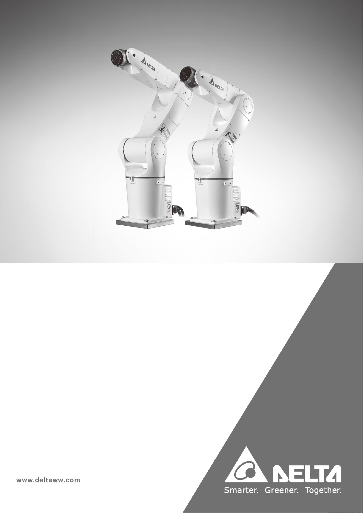
Delta Articulated Robot
DCV Controller
User Manual
Page 2

1
Preface
Thank you for using this product. This manual contains information related to the Delta Articulated
Robot series and provides instructions that you must follow to safely operate the robot. Before
operating the robot, read this manual carefully to ensure your safety and proper robot use. In addition,
keep this manual in a safe location for reference whenever required.
This manual applies to the DRV70L and DRV90L Series robots and the DCV Series robot controller.
The DRV70L and DRV90L Series robots work only with our company’s DCV Series controller. Do not
modify the robot and DCV controller or use it with other robots and controllers. Our company will not be
held responsible for any injuries or fatalities caused by accidents that result from doing so.
The following are the robot models and document numbers and versions for this manual.
Published By: Delta Electronics Inc.
Applicable Robots: DRV70L Series and DRV90L Series
Version: V1.0
The contents of this articulated robot manual include:
Precautions for safe controller use
Transportation and Installation
Controller installation and inspection
Safety protection
Wiring
Maintenance
Troubleshooting
Due to the varied working environments and operator safety, we provide special training for personnel
who work with articulated robots. Contact your local dealer or Delta for related training courses. This
manual is a reference for the following users:
System integration designer
Installation and wiring workers
Maintenance and inspection workers
Page 3

2
Caution
Read this manual carefully before operating the robot to ensure proper use. In addition, keep this manual
in a safe location for reference whenever required.
You will learn do to the following tasks when you have finished reading this manual:
Set up the robot in a safe and protected location with safety protection such as railings and gratings.
Do not operate the robot outside the safety protection area to prevent injuries to the operator.
The installation environment must have no steam, corrosive gas or flammable gas to prevent
accidents such as malfunctions or explosions.
Read this manual carefully before wiring the DCV controller and the robot to prevent damage to the
robot and the DCV controller.
The equipment must be grounded properly.
Do not disassemble or change the wiring while the power is on to prevent electrical shocks.
Ensure that the emergency stop device can be operated at any time before powering the robot on.
Turn off the power to the DCV controller before performing repairs or maintenance.
Do not get close to the operating range of the robot before and after powering on for operations, and
leave a warning in an obvious place to prevent injuries or fatalities to the workers.
If you have questions concerning the robot use, please contact your dealer or our company’s Customer
Service Center.
The copyright of this manual belongs to Delta Electronics Inc. This manual cannot be copied or
duplicated in whole or part without written approval from our company. Its contents must not be passed
on to a third party, nor can it be used for any unauthorized purposes. Any violations will result in a
lawsuit.
The contents and specifications in this manual may change without further notification. You can
download the latest version from the Delta website.
Page 4

3
Safety Notice
This manual includes safety precautions for user safety and to prevent damage to the robot. Warnings
and notes in this manual describe important safety precautions. Warnings describe supplementary
explanations. Users must read the items in the warning, danger and prohibited notes carefully to
prevent accidents or injuries to the workers.
Only qualified workers should install and transport the robot and they should comply with the regional,
country and local laws and regulation requirements.
The final system integrator should integrate the robot and the robot’s peripherals as well as execute the
construction of the safety protection devices to ensure the overall system safety.
This robot is designed only as an accessory for specific applications. We strongly suggest that you do
not modify this robot or use it for any application processes other than what it is designed for. If you
have any application problems, do not use the robot until you have received detailed explanations from
your dealer.
Definition of Robot Operators
Operator:
Able to perform operations such as powering the DCV controller ON/OFF.
Able to start the robot from the final system integrated operating panel.
Program Editor:
Performs operations with the robot.
Uses the manual mode to operate the robot or for teaching from outside the safety railings.
Repair or Inspection Worker:
Performs simple operations on the robot.
Uses manual mode to operate the robot from outside the safety railings.
Performs operations such as maintenance, repairs, adjustments and replacements to the robot and
DCV controller.
Note: Read this manual carefully before operating, maintaining or inspecting the robot and DCV
controller, and be sure to follow the safety regulations. Please contact our company for details if you
have any questions.
Page 5
4
Definitions of Prohibited, Danger and Warning
For your safety, read this manual before using the robot and have a clear understanding of all contents
related to safety and warnings.
The following table explains the symbols “Danger”, “Warning”,
“Prohibited” and “Noise Prevention”.
“Danger”
There is imminent danger of fatalities or severe injuries to the workers if not
prevented.
“Warning”
There is a potential danger of fatalities or severe injuries to the workers if not
prevented.
“Prohibited”
These activities are absolutely prohibited. Failure to comply may result in damage
or malfunctions in the product causing the product to be unusable or it may result
in injuries to the workers.
Noise Prevention
There is excessive noise that may affect the operator’s hearing when the robot is
operating. Operators should wear ear protection to protect their hearing.
Page 6
5
Installation Safety
Read this manual carefully before installing the robot to make sure that you install
the robot in a suitable location and environment to avoid affecting the mechanisms
and useful life of the electronic components, or encounter other safety problems.
The DRV70L and DRV90L Series robots can work only with our company’s DCV
Series controller. Do not modify the machine and wiring or use it with other
controllers. Our company will not be held responsible for any injuries or fatalities
caused by accidents that result from doing so.
Follow the instructions in this manual to correctly transport and install the robot and
DCV controller to prevent damage to the robot or DCV controller.
Related licenses are required for workers who operate equipment such as stackers
or forklifts.
Workers must wear proper safety work clothes, helmets, gloves and shoes when
installing the robot to ensure their safety.
On automated production lines, the operating range of multiple robots may overlap.
Make sure that they do not interfere with one another to prevent damage to the
robots from impacts.
Please do not add additional equipment such as cables or hoses inside the
mechanism. When installing the robot’s exterior cables, ensure that the cables and
mechanisms do not interfere with one another during operations.
Use only clean dry air (CDA) for the air source at the robot air hose input terminal.
You can use the robot in IP40 environments and it is able to resist solid matter with
a diameter over 1mm. It is not protected against any liquids.
Follow the manual and install the safety protection devices such as railings,
gratings, regional lasers or pressure pads to prevent injuries or other dangers to the
workers from impact with the robot in its operating range.
Install the user operating buttons and alarm indicators outside the railings to ensure
safe use. The operating interface should be at a suitable height (0.6–1.7 m) for
operators to reach easily.
Do not turn the power on and off frequently to prevent damage to the DCV
controller.
Install the robot system under the specified conditions; in the foreseeable use
period, the robot may not be tilted or moved by uncontrolled methods during
transportation, assembly, disassembly, suspended or discarded periods.
Properly ground all robot systems before connecting the power.
The final system integrator should install protection devices to prevent users from
getting close to the danger area.
Removing or changing the locations of any safety warning labels on the equipment
is strictly prohibited to prevent danger and injuries to the workers.
Performing any unsafe actions at the safety warning locations on the equipment is
strictly prohibited to prevent injuries to the staff.
Workers must not stand underneath when using equipment such as stackers or
forklifts to move the robot to prevent injuries or other dangers.
Placing objects on top of the robot, DCV controller or cables is strictly prohibited to
prevent damage to the robot, DCV controller or cables.
Changing or modifying the robot and DCV controller is strictly prohibited to prevent
damage to the robot or DCV controller and danger to the workers. Our company will
not be held responsible for any work accidents.
Installation and wiring the robot by unqualified people without the related
professional knowledge or licenses is strictly prohibited.
Page 7
6
Use and Operation Safety
Read this manual carefully before using the robot to ensure proper use and the
workers safety.
Due to varied operational environments and operator safety considerations, our
company provides dedicated training for personnel who work with the robot to
ensure safe use. Please contact our company or your local dealer if training is
needed.
Wire the robot according to this manual. The wiring must be performed by
qualified workers with related professional knowledge or licenses.
The DRV70L and DRV90L Series robots can work only with our company’s
DCV Series controller. Do not modify the machine and wiring on or use it with
other controllers. Our company will not be held responsible for any injuries or
fatalities caused by accidents that result from doing so.
Use our company’s handheld teaching pendant and install it on the DCV-2J00-
AA controller to perform manual operations and to edit programs.
Do not use this robot on production lines where there are flammable, explosive,
or toxic conditions or there is the risk of the robot being sprayed by liquids.
Select a suitable model according to the load capability. Do not exceed the
machine model specifications.
The robot is a partially completed machine. The assembly and construction of
the protection and safety circuits are the responsibility of the final system
integrator.
Keep all children and visitors a safe distance away from the robot’s operating
area.
Do not wear loose clothes, ties, rings or bracelets, and wear protective nets as
these things can get caught easily in the machine by accident and cause
injuries to the workers or other dangers during operations.
Turn off the power, isolate the power properly and wait for the robot to stop
completely when the robot is no longer in use before leaving the area.
Install safety protection devices such as railings, gratings, laser scanners or
pressure pads according to the instructions in the manual to prevent workers
from entering the working range of the robot and being injured by the robot.
Confirm that there is no one inside the railings before operating the robot.
Do not interact with other workers while operating the robot. A lack of attention
may result in a collision with the robot or injuries to other workers.
Install the user operating buttons and alarm indicators outside the railings to
ensure safe use. The operating interface should be at a suitable height (0.6–1.7
m) for operators to easily reach.
Use the key selection switch to change between modes. The keys must be able
to be removed in any mode.
The senior supervisor should keep the mode selection switch key. Do not drop it
carelessly or leave it inserted in the selection switch to prevent other workers
from accidentally activating the robot, and causing injuries to the workers.
Do not stand in the range of the robot when teaching the robot manually for the
first time to prevent danger from being unfamiliar with the operations.
Use slow speed operations when operating the robot manually for the first time;
otherwise unfamiliarity with the operations may result in damage to the robot
from impact or causing injuries to other workers.
Do not turn the power on and off frequently to prevent damage to the DCV
controller.
Page 8
7
Improper operations may damage the robot.
When a collision occurs involving the robot, first turn off the power to the robot
and then check the robot’s components and cables to make sure that they are
not damaged before turning the power back on and performing operations
again.
Use a safety lock on the railing switch when entering the railings to operate the
robot to prevent the railings from closing suddenly, causing the robot to be
activated accidentally.
Turn off the power before removing the teaching pendant cable from the DCV
controller to prevent damage to the teaching pendant.
The location of the interlock switch between the structure of the safety
protection device and the protection device should comply with EN ISO 14120
and EN ISO 14119 standards, and the safety distance should be designed
according to EN ISO 13857 standards.
Do not make any changes to any components on our company’s handheld
teaching pendant, including the Emergency Stop and Enable switches. Doing so
lowers the safety performance and level, or may even eliminate the safety
protection.
Short-circuiting any safety protection signals on the DCV controller is strictly
prohibited, and our company will not be held responsible for any work accidents
that may occur.
When operating the robot, all workers are prohibited from standing close to or in
the robot working range to prevent injuries to the workers.
Do not unplug any cables on the DCV controller while the robot is operating to
prevent damage to the DCV controller.
Do not open the protective cover or protection device while the machine and
robot are operating.
Maintenance Safety
Properly perform maintenance and inspection according to the manual to prolong
the useful life of the robot.
Add a safety lock on the power switch on the controller when performing
maintenance or repair operations to the robot, and place a “Do not power on” safety
warning in an obvious place.
Replacing damaged internal DCV controller components with other brands of
components is prohibited to prevent danger or decrease the safety performance
levels.
Make sure foreign objects do not get attached to, or enter the robot when
performing maintenance or inspection.
Use only oil that meets the specifications during maintenance to prevent damaging
the performance of the robot or the mechanical components.
Protection devices and repair doors in the danger areas that need to be opened or
removed regularly for the purpose of operations, maintenance, cleaning or
configuration should be interlocking.
Workers performing maintenance or repairs to the robot or robot system should
receive the necessary process training to execute the tasks required. Use only
genuine parts to prevent grave dangers to the workers.
The processing of waste material should comply with local laws and regulations,
and should be treated carefully.
Page 9

8
Any changes to the maintenance schedule of the robot and maintenance oil are
strictly prohibited.
Maintenance and inspection of the DCV controller and robot is prohibited while
power is on to prevent electrical shock or injuries to the workers.
When a robot component is damaged, replacing it with other brands of components
is prohibited to prevent damaging the performance of the robot or the components.
Wait 10 minutes before opening the controller box after powering it off because
there is residual voltage in the controller that may cause electrical shocks.
Page 10

9
Contents
DRV70L/90L Series Manual
Caution ............................................................................................ 2
Table of Contents ........................................................................... 9
1. Warning Label Explanations ................................................... 14
1.1 Warning Label Explanations ................................................................................. 16
1.2 Product Label Explanations .................................................................................. 17
2. Controller Specifications ......................................................... 19
2.1 Controller Specifications ....................................................................................... 21
3. Transport and Installation........................................................ 23
3.1 Transportation ...................................................................................................... 24
3.1.1 Transport of the Robot and Controller Together ....................................... 24
3.1.2 Transporting the Controller Alone ............................................................. 25
3.2 Installation ............................................................................................................ 26
4. Robot Safety Protection ........................................................... 28
4.1 Robot Safety Protection ....................................................................................... 29
4.2 Robot Safety Protection Construction and Installation ......................................... 30
4.2.1 Emergency Stop Device Installation ......................................................... 30
4.2.2 Emergency Pull-rope Device Installation .................................................. 31
4.2.3 Railings Installation .................................................................................. 32
4.2.4 Safety Gratings Installation ....................................................................... 34
4.2.5 Safety Mat Installation .............................................................................. 35
4.2.6 Laser Scanner Installation ........................................................................ 36
Page 11

10
5. Wiring ......................................................................................... 37
5.1 Construction of the Controller Peripheral System................................................. 39
5.2 Controller Interface Description ............................................................................ 40
5.2.1 Power Input .............................................................................................. 40
5.2.2 RS-232/485 Wiring ................................................................................... 42
5.2.3 Ethernet Connector .................................................................................. 43
5.2.4 DMCNET Connector ................................................................................ 43
5.2.5 Handheld Teaching Pendant Connector................................................... 46
5.2.6 Safety Connector ...................................................................................... 48
5.2.7 System. DI/O ............................................................................................ 51
5.2.8 User. DI/O ................................................................................................ 58
5.2.9 External Encoder ...................................................................................... 63
5.2.10 Robot Connector ...................................................................................... 64
6. Connecting with the Robot ...................................................... 65
6.1 Robot Signal Connector ....................................................................................... 67
6.2 Wiring of the Robot’s Built-in Solenoid Valve ....................................................... 68
7. Quick Wiring.............................................................................. 72
8. Maintenance .............................................................................. 77
8.1 Fan Filter Cleaning ............................................................................................... 78
9. Accessories............................................................................... 79
9.1 Controller Accessory Pack ................................................................................... 81
9.2 Optional Controller Peripheral Accessories .......................................................... 82
9.2.1 EMI Peripheral Accessories ..................................................................... 82
9.2.2 Extension Cord Accessories ..................................................................... 83
9.2.3 DI/O Expansion, Driver Accessories ........................................................ 83
9.2.4 Handheld Teaching Pendant .................................................................... 87
9.2.5 Robot Cable ............................................................................................. 87
Page 12

11
List of Figures
Figure 1.1 Sticker Locations on the Front of the Controller ................................................................... 16
Figure 1.2 Sticker Location Behind the Controller ................................................................................. 16
Figure 1.3 Product Label Location ......................................................................................................... 17
Figure 1.4 Product Label Location ......................................................................................................... 17
Figure 2.1 Controller Appearance and Dimensions .............................................................................. 22
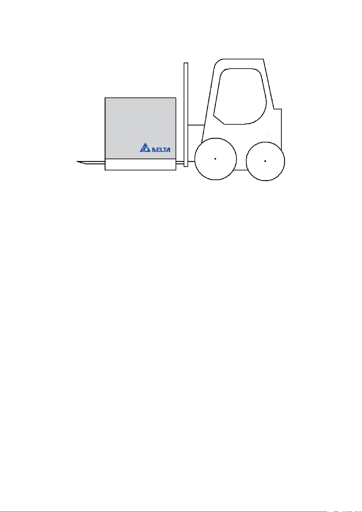
Figure 3.1 Fork Lift and Lift Icons .......................................................................................................... 24
Figure 3.2 Fork Lift Transportation Illustration ....................................................................................... 25
Figure 3.3 Controller Installation Space ................................................................................................ 27
Figure 4.1 Emergency Stop Button ....................................................................................................... 30
Figure 4.2 Emergency Stop Switch Reset Method................................................................................ 30
Figure 4.3 Emergency Stop Safety Disconnect Symbol ....................................................................... 30
Figure 4.4 Safety Pull-rope Switch Construction Example .................................................................... 31
Figure 4.5 Robot Installation and Railing Protection Installation Height ............................................... 32
Figure 4.6 Wrong Railings Installation Height ....................................................................................... 33
Figure 4.7 DRV70L Safety Grating Installation Distance ...................................................................... 34
Figure 4.8 DRV70/90L Safety Mat Laying Range ................................................................................. 35
Figure 4.9 Laser Scanner Installation Illustration .................................................................................. 36
Figure 5.1 Controller Peripheral System Composition .......................................................................... 39
Figure 5.2 Power Input Terminal Location............................................................................................. 40
Figure 5.3 Power Terminal Wiring ......................................................................................................... 40
Figure 5.4 Controller with EMI Filter and Electric Reactor .................................................................... 41
Figure 5.5 RS-232/485 Connector Location .......................................................................................... 42
Figure 5.6 Ethernet Connector Adapter Figure ..................................................................................... 43
Figure 5.7 DMCNET Connector Location .............................................................................................. 43
Figure 5.8 DMCNET Connection Figure ................................................................................................ 44
Figure 5.9 Controller with External Driver System Architecture Connected ......................................... 45
Figure 5.10 ASD-DMC-RM32MN .......................................................................................................... 45
Figure 5.11 ASD-DMC-RM32NT ........................................................................................................... 46
Figure 5.12 Handheld Teaching Pendant Connection Figure ............................................................... 46
Figure 5.13 Handheld Teaching Pendant Enabling Switch Figure ....................................................... 47
Figure 5.14 Handheld Teaching Pendant Bypass Connector Location ................................................ 47
Figure 5.15 Safety Connector Location ................................................................................................. 48
Figure 5.16 Wiring Example of a Single Emergency Stop Button ......................................................... 49
Figure 5.17 Wrong Wiring of a Single NC Emergency Stop ................................................................. 49
Figure 5.18 Wrong Wiring of a Single NC Emergency Stop with Safety Signal Connected ................. 49
Figure 5.19 Wiring Example of Multiple Emergency Stop Buttons ....................................................... 50
Figure 5.20 Wiring Figure of Multiple Safety Protection Devices .......................................................... 50
Figure 5.21 Safety Door Switch Figure .................................................................................................. 50
Figure 5.22 Electromagnetic Safety Switch Wiring ............................................................................... 51
Figure 5.23 System .DIO and DC Output Connector Locations ........................................................... 52
Figure 5.24 Input Signal DI Wiring ......................................................................................................... 52
Figure 5.25 System DO Controller Voltage Output NPN Wiring ........................................................... 53
Figure 5.26 System DO Controller Voltage Output NPN Wiring ........................................................... 53
Figure 5.27 System DO Controller Voltage Mixed Output Wiring ......................................................... 53
Figure 5.28 System DO Upper Controller Voltage Output NPN Wiring ................................................ 54
Figure 5.29 System DO Upper Controller Voltage Output PNP Wiring ................................................ 54
Figure 5.30 System DO Upper Controller Voltage Mixed Output Wiring .............................................. 54
Figure 5.31 User .DIO Jack Locations ................................................................................................... 59
Figure 5.32 NPN Wiring for When the Input Signal DI Uses the Power of the Controller Itself ............ 59
Figure 5.33 PNP Wiring for When the Input Signal DI Uses the Power of the Controller Itself ............ 59
Page 13

12
Figure 5.34 Input Signal DI Connected to the Upper Controller Using NPN Connection ..................... 60
Figure 5.35 Input Signal DI Connected to the Upper Controller Using PNP Connection ..................... 60
Figure 5.36 User DO Controller Voltage Output NPN Wiring ................................................................ 60
Figure 5.37 PNP Wiring for When the Input Signal DI Uses the Power of the Controller Itself ............ 61
Figure 5.38 User DO Controller Voltage Mixed Output Wiring .............................................................. 61
Figure 5.39 User DO Upper Controller Voltage Output NPN Wiring ..................................................... 61
Figure 5.40 User DO Upper Controller Voltage Output PNP Wiring ..................................................... 62
Figure 5.41 User DO Upper Controller Voltage Mixed Output Wiring ................................................... 62
Figure 5.42 External Encoder Connector Location ............................................................................... 63
Figure 5.43 Robot Connector Connection Location .............................................................................. 64
Figure 5.44 Robot Cable ........................................................................................................................ 64
Figure 6.1 Internal Wiring of the Robot 12Pos Signal Connector ......................................................... 67
Figure 6.2 Location of Solenoid Valve Inside the Robot ....................................................................... 68
Figure 6.3 Wiring Diagram of the Robot’s Built-in Solenoid Valve ........................................................ 68
Figure 6.4 Internal Wiring of the Robot’s 12Pos Signal Connector ....................................................... 69
Figure 6.5 TCP Terminal Air Pipe and Sensor Wiring Example............................................................ 70
Figure 6.6 Robot Clasping Jaw Signal and DCV Controller Connection Example ............................... 70
Figure 6.7 Wiring Example for Driving Solenoid Valve.......................................................................... 71
Figure 7.1 Emergency Stop Button and Safety Signal Wiring .............................................................. 74
Figure 7.2 Handheld Teaching Pendant Connection Method ............................................................... 74
Figure 7.3 Robot and Controller Connection ......................................................................................... 75
Figure 7.4 DI Quick Wiring Example ..................................................................................................... 75
Figure 7.5 Quick Wiring Example-Power Wiring ................................................................................... 76
Figure 7.6 Quick Wiring Example-Power ON Power Switch ON........................................................... 76
Figure 8.1 Controller Ventilation Filter Locations .................................................................................. 78
Figure 9.1 Delta Wave Filter 16DPCG5-1 Dimensions ......................................................................... 82
Figure 9.2 System DI/O Extension Cord (3081425800) Figure ............................................................ 83
Figure 9.3 User DI/O Extension Cord (3081425700) Figure ................................................................. 84
Figure 9.4 Safety Extension Cord (3081735000) Figure ....................................................................... 85
Figure 9.5 Ext.Encoder Extension Cord (3081427000) Figure ............................................................. 85
Figure 9.6 RS-232/485 Extension Cord (3081427100) Figure ............................................................. 86
Figure 9.7 RS-232/485 Extension Cord (3081427100) Figure ............................................................. 86
Figure 9.8 Robot Cable Figure .............................................................................................................. 87
Page 14

13
Tables
Table 1-1 Sticker Label Name ............................................................................................................... 16
Table 1.2 Product Label ......................................................................................................................... 18
Table 1.3 Controller Model Number Table ............................................................................................ 18
Table 2.1 Controller Specifications ........................................................................................................ 21
Table 3.1 Installation Distance Between the Robot and Railings ......................................................... 32
Table 3.2 DRV70L/90L Safety Grating Safe Distance Table ................................................................ 34
Table 3.3 DRV70L/90L Safety Mat Distance Table............................................................................... 35
Table 5.1 RS-232/485 Connector Pin Definition Table ......................................................................... 42
Table 5.2 RS-232/485 Connector Pin Definition Table ......................................................................... 48
Table 5.3 System DI/O Pin Definition .................................................................................................... 51
Table 5.4 Operation Mode Selection Table ........................................................................................... 55
Table 5.5 Run/Pause/Stop Selection Table .......................................................................................... 56
Table 5.6 Project Running Status Output Table .................................................................................... 57
Table 5.7 User. DI/O Pin Definitions ...................................................................................................... 58
Table 5.8 External Encoder Pin Definitions ........................................................................................... 63
Table 5.9 Robot Cable Pin Definitions ................................................................................................... 64
Table 6.1 Robot Signal Connector Pin Table ........................................................................................ 71
Table 7.1 Operation Mode Selection Table ........................................................................................... 75
Table 9.1 Controller Accessory Pack Contents ..................................................................................... 81
Table 9.2 EMI Accessory Specification Table ....................................................................................... 82
Table 9.3 Extension Cord Accessories Specification Table .................................................................. 83
Table 9.4 System DI/O Extension Cord (3081425800) Cable Color Table .......................................... 83
Table 9.5 User DI/O Extension Cord (3081425700) Cable Color Table ............................................... 84
Table 9.6 Safety Extension Cord (3081735000) Cable Color Table ..................................................... 85
Table 9.7 Safety Extension Cord (3081735000) Cable Color Table ..................................................... 85
Table 9.8 RS-232/485 Extension Cord (3081427100) Cable Color Table ............................................ 86
Table 9.9 Robot Arm Signal Extension Cord (3081734700, 3081734800, 3081734900) Cable
Color Table .............................................................................................................................. 86
Table 9.10 DI/O Expansion, Driver Accessories Table ......................................................................... 87
Table 9.11 Handheld Teaching Pendant Optional Purchase Table ...................................................... 87
Table 9.12 Robot Cable Specifications ................................................................................................. 87
Page 15

14
1. Warning Label Explanations
1.1 Warning Label Explanations ......................................................... 16
1.2 Product Label Explanations .......................................................... 17
Page 16
1. Warning Label Explanations
15
1. Warning Label Explanations
This section describes the location and meaning of the safety warning stickers. Operators should be
familiar with the locations of the safety warning labels before using the robot and know the meanings of
each safety warning to prevent accidents.
Be aware of the locations of the safety warning labels during operations to
prevent worker injuries.
Operators should be aware of the locations of the safety warning labels before
use and know the meanings of each safety warning.
Removing or changing the location of any safety warning labels is strictly
prohibited to prevent danger or injury to the workers.
Performing any unsafe actions at the safety warning locations is strictly
prohibited to prevent injuries to the workers.
Page 17
DRV70L/90L Series Manual
16
1.1 Warning Label Explanations
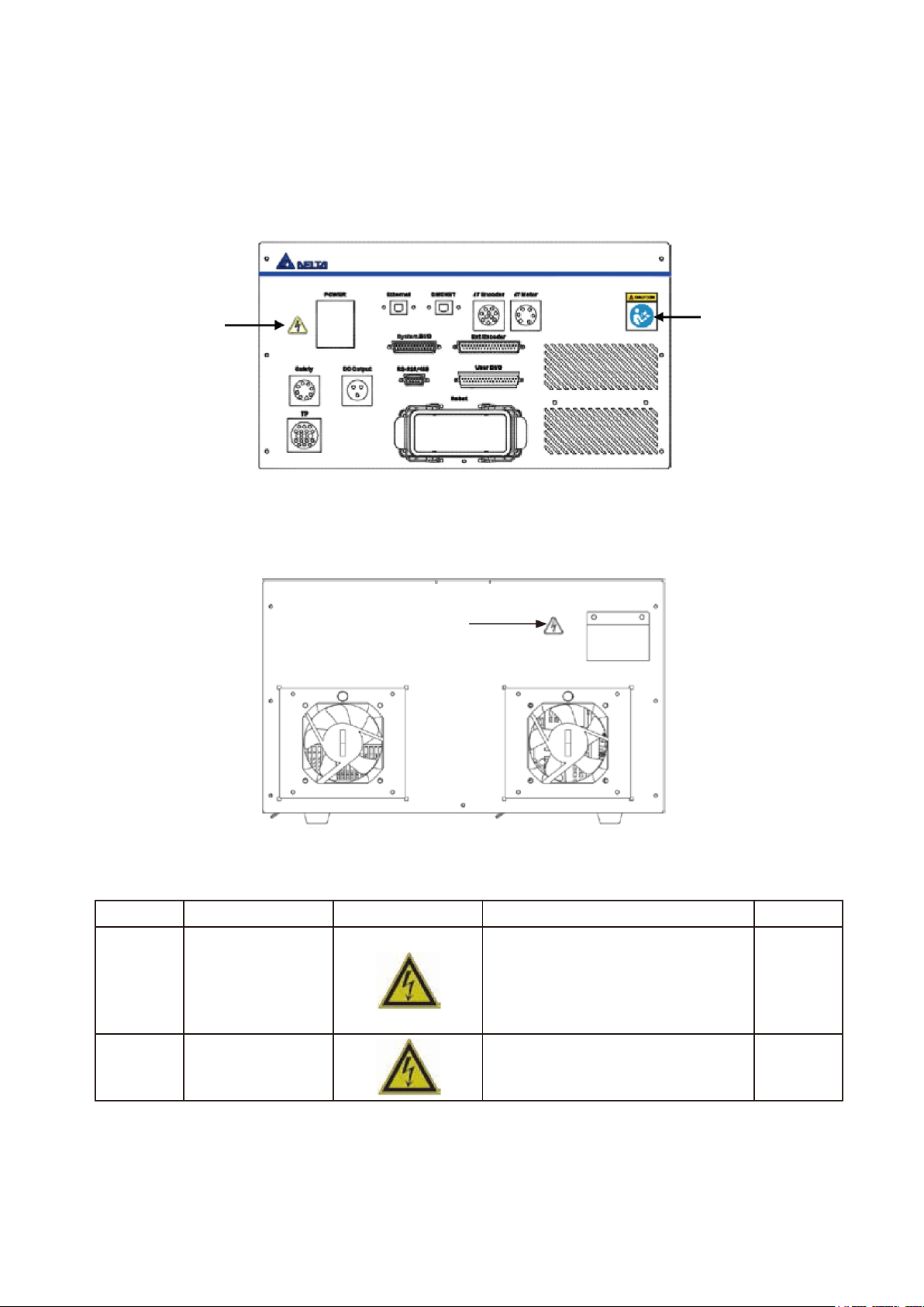
There are two stickers on the front of the DCV controller: the High Voltage Warning sticker and the Read
Before Use sticker, which are attached to the left and right sides of the DCV controller as shown in Figure
1.1.
Figure 1.1 Sticker locations on the front of the controller
There is a high voltage warning sticker on the back of the DCV controller, as shown in Figure 1.2.
Figure 1.2 Sticker location on the back of the controller
Table 1-1 Sticker Label Name
Item
Name
Flag
NOTE
Qty
1
High Voltage Warning
The high voltage warning label means
that high voltage exists in the switch or
component; do not disassemble the
component while the power is turned on
to prevent electrical shock and other
danger.
2
2
Read Before Use
Read the product manual and configure
related surrounding safety protections
before use to prevent danger.
1
Read Before Use
High Voltage
Warning
High Voltage Warning
Page 18

1. Warning Label Explanations
17
1.2 Product Label Explanations
The product label is located on the right side of the DCV controller, and shows DCV controller related
information. Figure 1.3 shows the location of the DCV controller product label.
Figure 1.3 Product label location
Figure 1.4 shows the DCV controller product label sticker.
Figure 1.4 DCV controller product label information
Controller product label
Page 19
DRV70L/90L Series Manual
18
Table 1.2 lists the detailed DCV controller product label explanation.
Table 1.2 Controller product Label
Item
Name
Description
a) )
MODEL
Controller Model Number
b) )
Document No
Controller Document Name
c) )
S/N
Controller Product Serial Number
d) )
Power Supply
Required Controller Power Voltage and Frequency
e) )
Short Circuit Rating
Controller Short-circuit Current Capacity
f) )
Address & TEL
Company Address and Contact Number
g) )
Manufactured Date
Manufacture Date
h) )
Weight
Controller Weight
i) )
Rated Power
Controller Maximum Power
j) )
Rated Current
Controller Rated Current
k) )
QR Code
Service QR code
l) )
QR Code
QR Code of Related Information of this Product
Table 1.3 lists the detailed descriptions of the DCV controller model number.
Table 1.3 Controller Model Number
D C V–2 J 0 0–A A
Code
Definition
Definition
Description
(a)
DC
Product Series
Delta Controller
(b) V Type of Pairing Robot
S: SCARA V: Vertical
(c) 2 Generation
(d) J Type of Controller
Drive
(e)
0
Built-in Expansion Shaft
0: No Expansion Shaft; 1:1 Shaft
(f) 0 Reserved
(g) A Certification
A: Standard C: CE U: UL
(h) A Reserved
Notes:
1. Only use robots with controllers that are specified to work together to prevent abnormal operation or damage to
the robot.
2. The DCV Series controller is suitable for operation with the DRV70L and DRV90L Series robots.
Page 20

19
2. Controller Specifications
2.1 Controller Specifications ............................................................... 21
Page 21
DRV70L/90L Series Manual
20
2. Controller Specifications
This chapter introduces the specifications and dimensions of the DCV controller, Use the DCV controller
according to the specifications.
Use the robot according to the specified methods to prevent fire, equipment
failure, or even worker injuries or fatalities and other danger.
Do not use this product in locations with substances such as steam, corrosive
gas and flammable gas to prevent electrical shocks or fire.
Read this manual carefully before installation to make sure that you install the
robot in a suitable location and environment to avoid affecting the mechanisms
and shortening the useful life of the electronic components, or causing other
safety problems.
The DRV70L and DRV90L Series robots can work only with our company’s
DCV Series controller. Do not modify the machine and wiring or use it with other
controllers. Our company will not be held responsible for any injuries or fatalities
caused by accidents that result from doing so.
The robot can be used in IP40 environments and is able to resist solid matter
with a diameter over 1mm. It is not protected against any liquids.
Keep the working range of the robot clean and ensure that the robot is not used
in environments affected by substances such as oil, water and dust.
Use only clean dry air (CDA) as the air source at the input terminal of the robot
air hose.
Use of this robot in non-specified environments is prohibited to prevent damage
to the robot or reduce its useful life.
Do not make any changes to the robot’s specification tables.
Making changes or modifications to the robot is prohibited. Our company will not
be held responsible for any safety problems resulting from doing so. Please
contact our company if other specifications are needed.
Page 22
2. Controller Specifications
21
2.1 Controller Specifications
The DCV controller includes the Servo Drive and the safety circuit in one integrated unit. Do not modify
the DCV controller parts and wires to prevent abnormal operation or damaging the components. Read
this operation manual carefully before use. Table 2.1 lists the DCV controller specifications.
Table 2.1 Controller Specifications
DCV Series Controller
Power
Single Phase: 200–230 Vac +PE, 15 A, 50/60 Hz
Dimensions (W) x (H) x (D) mm
/Weight
383 x 223 x 406 mm / 22 kg
Cooling Method
Fan cooling
Robot Control
Program
Language
Delta Robot Language
Movement Mode
Point-to-point movement, linear interpolation, circular interpolation
Memory Capacity
20 MB: For user-defined program and data
1 K Position: For global variables (shared by different programs)
30 K Position: For program editing by all users
I/O
Standard DI/O
System DI/O: 7-set input, 8-set output
User-defined DI/O: 24-set input, 12-set output
Interface
Ethernet
1 Channel, RJ-45
DMCNET
1 Channel, RJ-45: For connecting to Delta DMCNET products.
485-232 / RS-RS
1 Port, D-sub 9-Pin/Female
Teach pendant
1 Circular connector
Safety
8-Pin circular connector
Two sets of dual-channels provided to connect external emergency stop
buttons, and two sets of dual-channels to connect safety protection devices.
Ext .Encoder
D-sub 37-Pin/Female: Provides one set of connections for feedback from
an external Encoder.
DC Power
3-Pin circular connector provided for user-defined DI/O connection
selection.
Power IN
3-Pin connector terminal block for the AC power.
Robot
European-spec. Multi-class connector/Female
Environmental
Specifications
Installation
Location
Indoors (avoid direct sunshine), non-corrosive vapor (no fumes,
combustible gas or dust).
Elevation
Below 1000 m in altitude
Atmospheric
Pressure
86–106 kPa
Environmental
Temperature
0–40ºC (if the ambient temperature is over 45ºC, use forced air circulation
for cooling).
Humidity
Below 0–90% RH (non-condensing)
Vibration
Below 20 Hz 9.80665 m/s2 ( 1 G ), 20–50 Hz 5.88 m/s2 ( 0.6 G )
IP Level
DCV controller IP20; robot IP40
Ground System
TN System: The neutral point of the electrical system must be connected to
the ground. The exposed metal component must also be connected to the
ground through a protective grounding conductor.
Page 23
DRV70L/90L Series Manual
22
Figure 2.1 shows the DCV controller dimensions.
Figure 2.1 Controller appearance and dimensions
Controller Installation Notes:
Do not put your fingers or foreign matter into the DCV controller cooling fan to prevent injury.
This DCV controller does not have explosion-proof or splash-proof containment, so do not use it in
locations that are too humid or can be splashed by liquids.
Read this manual carefully before moving, installing, wiring and using this equipment.
Do not stack objects on top of the DCV controller, and do not bump into the DCV controller.
Do not install the DCV controller in a location that is subject to excessive vibration.
Do not plug or unplug the power while the DCV controller is ON status or operating to prevent
damage to the robot’s and DCV controller’s internal components. The input power of the DCV
controller is 200–230 Vac, 50/60 Hz. Do not connect non-specified voltages to prevent damage to
the DCV controller or inaccurate robot movements.
Page 24

23
3. Transport and Installation
3.1 Transportation .............................................................................. 24
3.1.1 Transport of the Robot and Controller Together ................ 24
3.1.2 Transporting the Controller Alone ..................................... 25
3.2 Installation .................................................................................... 26
Page 25
DRV70L/90L Series Manual
24
3. Transport and Installation
Follow the transportation and installation instructions in the manual to prevent dropping and damaging
the robot or DCV controller.
Only qualified workers with related licenses can operate equipment such as
stackers and forklifts when transporting the robot.
There are precision electronic components inside the robot. Be careful not to
allow this device to collide with other objects during transport.
Workers must not stand underneath the transported object when operating a lift.
Workers must direct the operation from the side (in addition to the lift operator)
to prevent accidents.
Be careful not to tilt the robot when using a lift to prevent injuries.
Remember to wear safety shoes and safety gloves when manually moving the
DCV controller to prevent injuries.
3.1 Transportation
3.1.1 Transport of the Robot and Controller Together
Figure 3.1 shows the two methods to transport the robot: forklift or lift.
Forklift
Lift
Figure 3.1 Forklift and lift
Notes:
1. Operators must have related licenses when using forklifts or lifts, or have an equal number of
training hours before performing operations to prevent damage to the robot and to prevent injuries
to the workers.
2. Properly extend the forklift under the wooden pallets as shown in Figure 3.2 to prevent tilting
injuries.
3. Elevate the forklift or lift until it is off the ground and make sure it is not tilted to prevent dropping the
product during transportation. When moving uphill or downhill, adjust the height or tilt angle of the
forklift accordingly so that the product does not tilt, or secure the product in advance.
4. Check for anyone close by during transport. There should be workers on the sides who are
responsible for guiding and directing (in addition to the lift operator). Operate the lift at the speed set
by the company rules. Do not operate the lift at a high speed.
Page 26
3. Transport and Installation
25
Figure 3.2 Forklift transportation example
3.1.2 Transporting the Controller Alone
1. Use a van for transportation.
2. When transporting the DCV controller with you hands, lift and support the DCV controller from the
bottom.
Fork Lift
Page 27
DRV70L/90L Series Manual
26
3.2 Installation
Read this manual carefully before installing the robot to make sure that you
install the robot in a suitable location and environment to avoid affecting the
mechanisms and useful life of the electronic components, or encountering other
safety problems.
The DRV70L and DRV90L Series robots can work only with our company’s
DCV Series controller. Do not modify the machine and wiring or use it with other
DCV controllers. Our company will not be held responsible for any injuries or
fatalities caused by accidents that result from doing so.
Install the robot system under the specified conditions; in the foreseeable usage
period, the robot may not be tilted or moved by uncontrolled methods during
transportation, assembly, disassembly, suspended or discarded periods.
Workers must wear proper safety work clothes, helmets, gloves and shoes
when installing the robot to ensure their safety.
On automated production lines, the operating range of multiple robots may
overlap. Make sure that they do not interfere with one another to prevent
damage to the robots from impacts.
Do not add additional equipment such as cables or hoses inside the
mechanism. When installing cables outside the mechanism, ensure that the
cables and mechanisms do not interfere with one another during operations.
Turn the power off before performing peripheral equipment adjustments.
Use only clean dry air (CDA) for the air source at the input terminal of the robot
air hose.
Since the robot is a semi-finished product, if you add other operating modules or
make any modifications, the original manufacturer will not be held responsible
for any resulting problems.
The robot can be used in IP40 environments and is able to resist solid matter
with a diameter over 1 mm and a length not exceeding 80 mm.
Keep the working range of the robot clean. Ensure that the robot is not used in
environments with contaminants such as oil, water and dust.
Follow the manual and install safety protection devices such as railings,
gratings, regional lasers or pressure pads to prevent injuries or other dangers to
the workers from impact by the robot.
Install the user operating buttons and alarm indicators outside the railings to
ensure safe use.
Properly ground all robot systems before connecting the power.
The final system integrator should install safety protection devices to prevent
workers from getting close to the danger area.
The robot does not have explosion-proof or splash-proof structures, so do not
place it in locations that are too humid or where the robot can be easily
splashed by liquids.
Do not place objects on top of the robot and do not bump into the robot.
Do not place any objects on top of the cables connecting the DCV controller and
robot to prevent damage to the cables and to prevent injuries.
Page 28
3. Transport and Installation
27
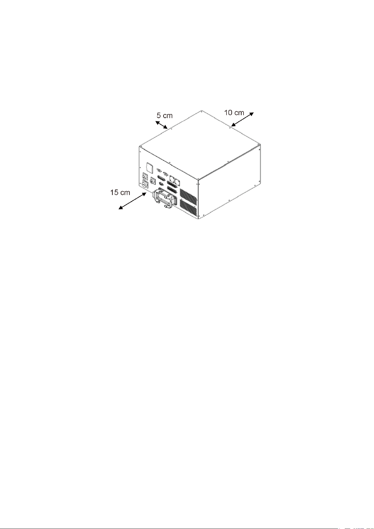
The DCV controller uses forced air fan cooling. Do not place the DCV controller against the wall during
installation to prevent poor DCV controller cooling. Keep the back of the DCV controller at least 10 cm
away from walls or barriers, and leave a space of at least a 5 cm on the left side. The connection interface
and cooling air inlet are in the front of the DCV controller, so leave a space of at least 15 cm to ensure
efficient cooling and so the cables can be installed properly.
Figure 3.3 shows the installation distances around the DCV controller.
Figure 3.3 Controller installation spacing
Page 29

28
4. Robot Safety Protection
4.1 Robot Safety Protection ............................................................... 29
4.2 Robot Safety Protection Construction and Installation .................. 30
4.2.1 Emergency Stop Device Installation .................................. 30
4.2.2 Emergency Pull-rope Device Installation ........................... 31
4.2.3 Railings Installation ........................................................... 32
4.2.4 Safety Gratings Installation ............................................... 34
4.2.5 Safety Mat Installation ....................................................... 35
4.2.6 Laser Scanner Installation ................................................ 36
Page 30

4. Robot Safety Protection
29
4. Robot Safety Protection
The final system integrator must follow the instructions in this manual to
construct a safe overall protection system for the robot to prevent injuries or
fatalities to workers.
Once the safety protection system and wiring are completed, then you can
connect power to the DCV controller and operate the robot.
Follow the instructions in this manual for the safety protection and wiring, or our
company will not be held responsible for any injuries sustained by the workers.
Do not perform any operations with the robot before the safety protection
system construction is complete.
Do not bypass the safety protection system. The safety protection system
includes the Emergency Stop signal, railings, pressure pad, gratings, laser
scanners and any safety device signals that protect the workers.
4.1 Robot Safety Protection
Robot safety protection refers to the protection equipment set up around the robot. These prevent workers
from getting close to the robot while it is operating and being accidently hit by the robot. The final system
integrator should properly construct the safety protection devices to ensure that the workers do not get
hit and injured by the robot.
The complete robot safety protection should include:
1. Emergency Stop Device
Must be a dual-channel NC contact mechanical type emergency stop device.
This type of device can be an Emergency Stop button, pull-rope switch or a similar device.
2. Railings, Gratings, Pressure Pads or Laser Scanners
Use equipment such as railings, gratings, pressure pads or laser scanners in the working range of
the robot to prevent workers from getting close and being injured.
The maximum working range of the robot must be considered for the protection range.
3. Teaching Pendant Enable Switch
This is the third switch on the back of the teaching pendant. You must press the Enable switch when
manually performing teaching point operations to teach the robot. You stop robot operations by
either releasing the switch or by pressing the switch all the way to the bottom.
Page 31

DRV70L/90L Series Manual
30
4.2 Robot Safety Protection Construction and Installation
4.2.1 Emergency Stop Device Installation
This must be a dual-channel NC contact mechanical type emergency stop device.
When using the Emergency Stop button:
1. The button must be red with a yellow background (the area of the yellow background must be
greater than the area of the red), as shown in Figure 4.1.
Figure 4.1 Emergency Stop button
2. It must be equipped with a manual reset function, as shown in Figure 4.2.
Pulling Reset
Rotation Reset
Figure 4.2 Emergency Stop switch reset method
3. It must be equipped with a disconnect function so that when the contacts are closed,
pressing the button disconnects the closed contacts.
This function symbol is shown in Figure 4.3.
Figure 4.3 Emergency Stop Safety Disconnect symbol
4. Install multiple emergency stop devices according to the actual overall system, and do not
make the installation distance between each emergency stop device so far that a worker
cannot press the button when an emergency event occurs.
Make sure the height of the Emergency Stop button is not too high or low. Install it at a height
that is accessible to workers.
The Emergency Stop buttons must be installed in obvious places that cannot be blocked by
other devices.
Page 32
4. Robot Safety Protection
31
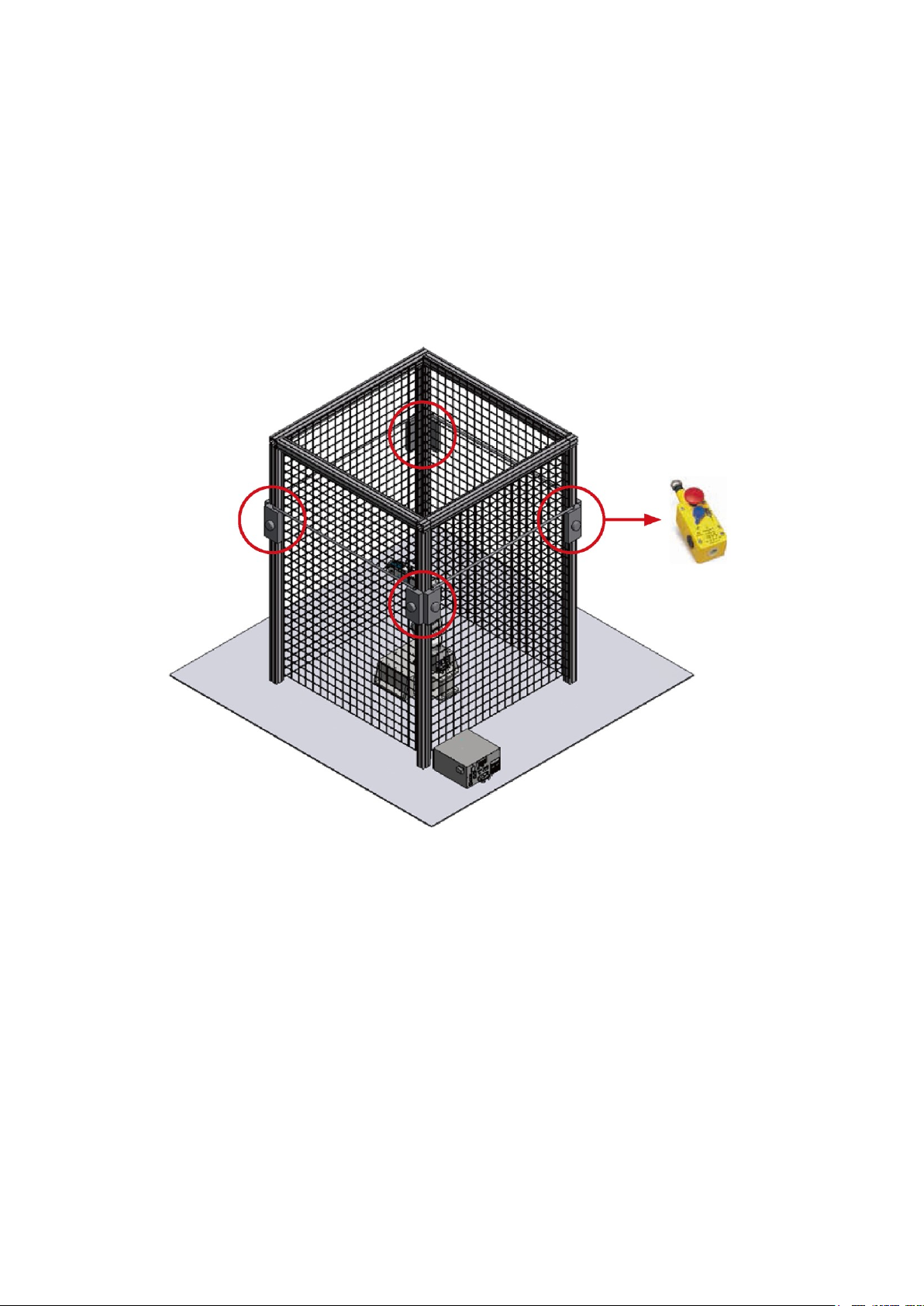
4.2.2 Emergency Pull-rope Device Installation
This must be a dual-channel NC contact mechanical device, and must have a reset button. The
pull-rope must be able to be triggered from any position.
Install the pull-rope at an accessible height for workers of average height. Installing it too high
results in workers being unable to reach it.
The railing protection is still needed after you install the pull-rope switches. The pull-rope
switches are there so that the emergency stop function can be triggered from any position.
When installing emergency pull-rope devices, place them around the entire safety protection
railing as shown in Figure 4.4.
Figure 4.4 Safety pull-rope switch installation example
Safety pull-rope device
Page 33
DRV70L/90L Series Manual
32
4.2.3 Railing Installation
Disconnect the DCV controller power before performing adjustments to surrounding devices. Confirm
that the robot arm has stopped operating completely before performing adjustments according to EN
ISO 13857 (EN294&EN811) Safety Distance for Upper and Lower Limbs.
You must consider the operating range of the robot arm height in setting the height of the railings, as
well as the distance to worker contact and the time for the robot arm to stop moving after the power has
been disconnected. Figure 4.5 shows the recommended installation distance for operating the DRV70L
robot arm in full stroke (when the railing height is 2 m). Table 3.1 lists the installation distances between
the robot and the railings.
Figure 4.5 Installation height for railings around the robot
Table 3.1 Installation Distance between the Robot and Railings
a b c d H
Machine
installation
height
Machine height
Railings should
be higher than
the machine
height
Railings distance
should be
greater than the
table distance
Height under the
fence
DRV70L
30–100 cm
68±3 cm
Over 100 cm
Over 30 cm
5–20 cm
DRV90L
30–100 cm
68±3 cm
Over 100 cm
Over 30 cm
5–20 cm
Protective structure
Height
a: Height of hazard zone
b: Height of robot
c: Height of protective structure
d: Horizontal safely distance to hazard zone
H : Vertical safety distance
Page 34
4. Robot Safety Protection
33
In addition, consider the length of the workers’ arms so that the workers cannot touch the robot.
Figure 4.6 shows an insufficient railing installation height: the worker’s arm can still reach inside the
railing. The height of the railing must be set according to the specifications to prevent worker injuries or
fatalities.
Figure 4.6 Insufficient railing installation height
Page 35
DRV70L/90L Series Manual
34
4.2.4 Safety Grating Installation
The safety grating system shall comply with IEC 61496-1 and -2.
Improper installation and use risks the workers being hit by the robot arm.
Set up the grating system around the robot so that the grating system can detect workers no matter where
they enter from.
DRV70L/90L Safety Grating Protection Area
Figure 4.7 shows the DRV70L safety grating installation distances. Table 3.2 lists the grating distances.
Figure 4.7 DRV70L safety grating installation distances
Table 3.2 DRV70L/90L Safety Grating Safe Distances
DRV70L/90L safety grating safe distances
Item Number
Model Number
X Y 1
DRV70L
≥ 810
≥ 810
2
DRV90L
≥ 1000
≥ 1000
Working Space
Safeguarded space
Interlocked gate
Page 36

4. Robot Safety Protection
35
4.2.5 Safety Mat Installation
The safety mat shall comply with EN 1760-1 (ISO 13856-1), and shall be able to detect operators over
35 kg.
Installing a safety mat is another type of protection system around the robot. Since safety mats rest on
the floor, the do not have height protection like railings. Calculate the size of the safety mats according
to the total moving range of the robot arm.
Do not place safety mats around the robot when it is in use, and cover the entire working area with the
safety mat.
DRV70L/90L Safety Mat Installation Area
Figure 4.8 shows the safety mat installation area for the DRV70L/90L. In addition to calculating the
maximum work area of the robot, add an average of 1 m for worker arm length to prevent the workers’
arms from hitting the robot. The actual installation takes into consideration the arm length of most workers
in that area. Table 3.3 lists the safety mat distances.
Figure 4.8 DRV70/90L safety mat area
Table 3.3 DRV70L/90L Safety Mat Distances
DRV70/90L safety mat distances
Item Number
Model Number
W mm
Z mm
1
DRV70L
≥ 2420
≥ 2800
2
DRV90L
≥ 2420
≥ 2800
Page 37

DRV70L/90L Series Manual
36
4.2.6 Laser Scanner Installation
When installing the laser scanner, take into consideration both operating range of the robot and the
distance that the workers’ arms reach into the robot.
The laser scanner cannot detect a full 360°, so another laser scanner for blind spots or where there are
safety concerns. Figure 4.9 shows a laser scanner installation.
Figure 4.9 Laser scanner installation
Page 38

37
5. Wiring
5.1 Construction of the Controller Peripheral System ......................... 39
5.2 Controller Interface Description .................................................... 40
5.2.1 Power Input ...................................................................... 40
5.2.2 RS-232/485 Wiring ........................................................... 42
5.2.3 Ethernet Connector ........................................................... 43
5.2.4 DMCNET Connector ......................................................... 43
5.2.5 Handheld Teaching Pendant Connector ........................... 46
5.2.6 Safety Connector .............................................................. 48
5.2.7 System. DI/O .................................................................... 51
5.2.8 User. DI/O ......................................................................... 58
5.2.9 External Encoder .............................................................. 63
5.2.10 Robot Connector ............................................................... 64
Page 39

DRV70L/90L Series Manual
38
5. Wiring
This chapter introduces the wiring for the peripheral systems, the DCV controller and the robot.
The robot is a semi-finished product system. You must construct the additional equipment such as safety
protection systems, operation buttons and lamps around the robot according to the instructions in this
manual to ensure the integrity and safety of the entire system.
Perform wiring according to the explanations in the manual.
Install safety protection devices around the robot, such as railings, safety
gratings, pressure pads or laser scanners to guarantee the safety of the
workers.
Turn off the power during wiring to prevent a danger of electrical shocks.
Do not perform any wiring within 10 minutes of turning off the power because
there is residual voltage in the DCV controller that has not yet been fully
discharged.
Wiring operations shall be performed by workers with related licenses. Workers
without related licenses shall not perform wiring operations.
Workers without related licenses shall not perform wiring operations.
Do not bypass the safety protection system. The safety protection system
includes the emergency stop signal and railing signal.
The emergency stop signal and railing signal are no-voltage contact signals. Do
not connect any AC or DC power to them to prevent damage to the DCV
controller.
Do not modify any wiring inside the DCV controller. Our company is not
responsible for any DCV controller malfunctions or damage resulting from doing
so.
Page 40
5. Wiring
39
5.1 Construction of the Controller Peripheral System
The DCV robot controller is integrated with the servo drive control. You can use this DCV controller with
visual systems and teaching pendants. You can expand the system with servo drives or remote
input/output modules to easily complete integration with peripheral systems. Figure 5.1 shows a
schematic of the combination of DCV controller interface peripherals.
Note: The extendable drives and remote input/output modules must be operated with Delta DMCNET
products.
Figure 5.1 Controller peripheral system components
Encoder
DI/DO expansion module
Expansion shaft
Lamp
Button switch
Delta vertical articulated robot
Grating
Fence
Emergency
Stop button
Handheld teaching pendant
Mechanical Visual System
Lamp
Button switch
Robot controller
Ethernet
Flexible Expansion: Expanded to eight stations maximum
(4-axis + 4 station DI/O maximum for se rvo drive A2 series)
Servo motor
Servo drive
Page 41

DRV70L/90L Series Manual
40
5.2 Controller Interface Description
The following sections describe the DCV controller interface and explain the interface function and the
wiring.
5.2.1 Power Input
Figure 5.2 shows the power input terminal located on the back of the DCV controller.
Figure 5.2 Power input terminal location
The DCV controller power is single-phase, 200–230 Vac, 50/60 Hz, 15 A. Connect the power terminal
with a power cables of at least 2.0 mm diameter and use 2.0 mm diameter ground cables (yellow/green).
To prevent the terminal from becoming loose and causing danger, lock the power cable tightly in place
and use R-type terminal wiring as shown in Figure 5.3.
L and N are power cables and E is the ground cable.
Figure 5.3 Power terminal wiring
Power input
terminal location
Power input terminal cover
Page 42

5. Wiring
41
I
nstall an EMI filter and electric reactor before the DCV controller to ensure that the DCV controller is not
affected by EMI noise interference or harmonic waves. Figure 5.4 shows the related wiring.
Figure 5.4 Controller with EMI filter and electric reactor
Reactor
Single-phase, 200–230
Vac, 50/60 HZ, 15 A,
28 mH or above
EMI filter
Page 43

DRV70L/90L Series Manual
42
5.2.2 RS-232/485 Wiring
The DCV controller has a standard D-Sub 9-Pin/Female connector. You can communicate with the
DCV controller using DCV controllers such as a PC, PLC or HMI that support RS-232/485
communications. You can read the robot data and control the robot. In addition, you can also use DCV
controllers that support RS-232/485 communication to read and write data to the DCV controller.
Figure 5.5 shows the location of the RS-232/485 connector.
Figure 5.5 RS-232/485 connector location
Use shielded twisted-pair cables to prevent interference in data transmission for the connections. Table
5.1 lists the RS-232/485 pin definitions.
Table 5.1 RS-232/485 Connector Pin Definitions
PIN
NAME
PIN
NAME
PIN
NAME
1
+RS-485
2
RS-232/RX
3
RS-232/TX
4 5
GND
6
RS-485 7 8 9
Page 44
5. Wiring
43
5.2.3 Ethernet Connector
You can use a PC for communication with the DCV controller by connecting an Ethernet cable to the
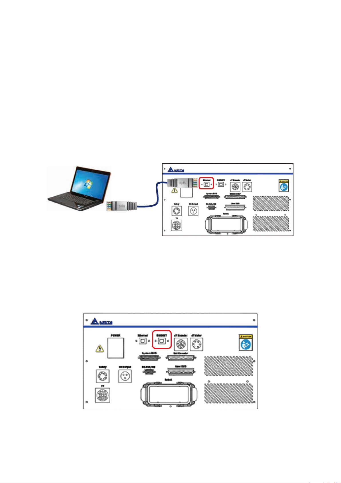
DCV controller. In addition, you can perform the following tasks through the Delta DROE software:
Edit the Robot Program Language and save the program into the DCV controller for project
management.
Perform tasks such as Jog the robot, set the origin and reset the origin.
Set the servo and robot related parameter settings.
Execute I/O monitoring.
Monitor alarms and troubleshoot problems.
Refer to the descriptions in the Delta DROE Operation Manual for the detailed operating instructions for
the DROE software.
Figure 5.6 shows the location of the Ethernet connector.
Figure 5.6 Ethernet connector location
5.2.4 DMCNET Connector
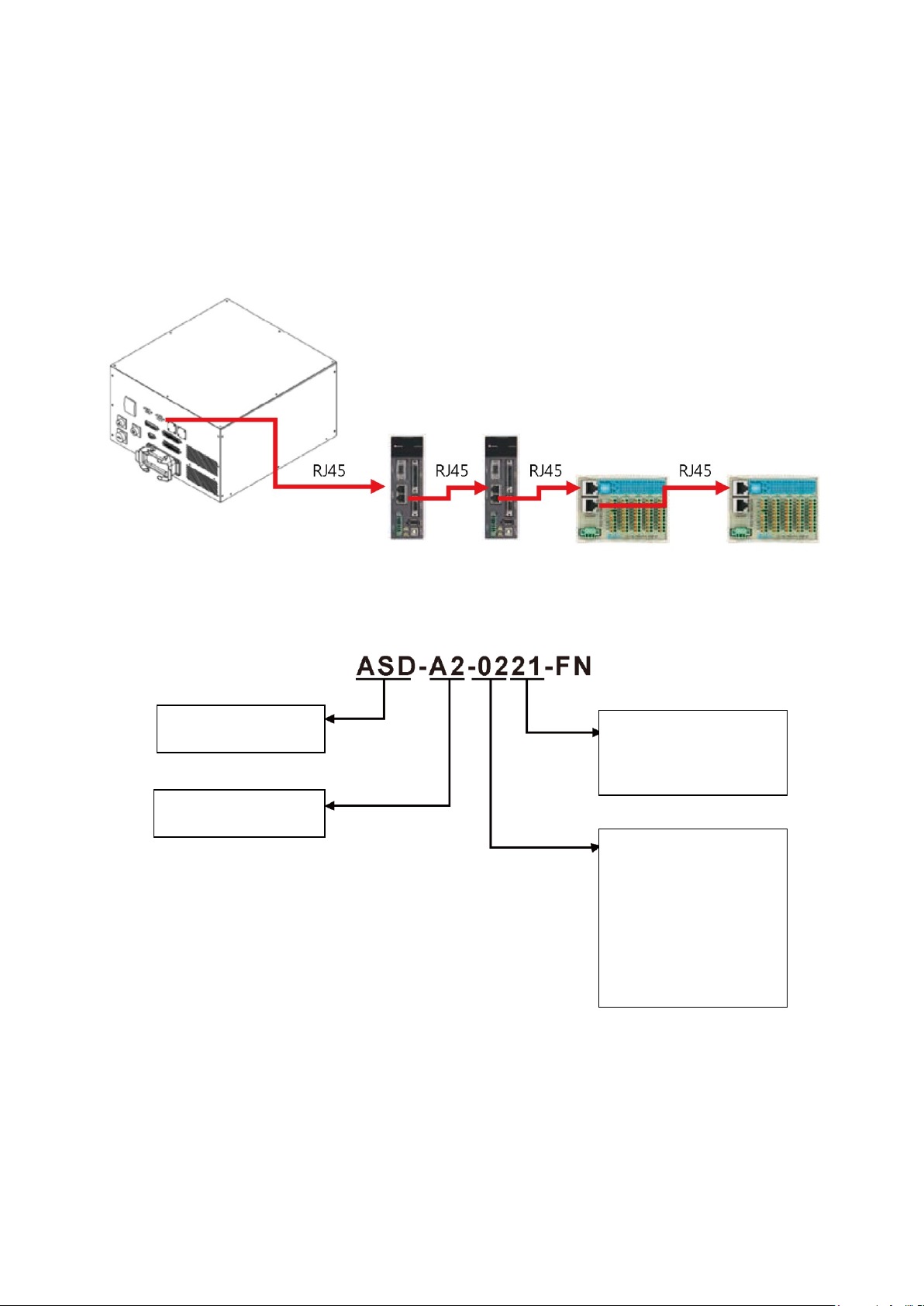
You can connect various Delta products through the Delta high speed communication network DMCNET,
such as servo drives and remote DI/O modules. Figure 5.7 shows the DMCNET connector that accepts
one end of a standard RJ45 cable to the DCV controller interface. You can then connect the other end to
the Delta DMCNET product.
Figure 5.7 DMCNET connector location
Page 45
DRV70L/90L Series Manual
44
You can connect a maximum of 12 Delta product workstations equipped with the DMCNET function
through the DMCNET connection, as shown in Figure 5.8.
Note:
1. When you connect an external servo drive to the DMCNET connection, if the controller is a six-axis
controller, you can connect at most a four-axis external driver. If the controller is a seven-axis
controller, you can connect at most a three-axis external driver.
2. If the connected DMCNET unit has no driver, you can connect a maximum of 12 DI-O module units.
Figure 5.8 Multiple DMCNET connections
The following figure shows the driver models that you can connect through DMCNET.
Input voltage and phase
count:
21: 220 VAC, 1 phase
23: 220 VAC, 3 phase
Drive rated power:
01 :W100
02 :W200
04 :W040
07 :W750
10 :KW1
15 :KW1.5
20 :KW2
30 :KW3
Product name:
AC s ervo drive
Product series name:
A2 Series
Page 46

5. Wiring
45
When connecting an external expansion axis servo drive, add an electromagnetic contactor before the
servo drive. Figure 5.9 shows how you control the electromagnetic contactor by using the upper controller
(for example, a PLC) or an emergency stop to cut off the AC power to the servo drive.
Figure 5.9 Controller with external servo drive system architecture
The DI/O modules models that can be connected are listed below.
Input Module:
ASD-DMC-RM32MN
32-point input module.
Input signal: By connecting to the COM point, you can select PNP or NPN for the input signal.
Figure 5.10 ASD-DMC-RM32MN
Shorting COM and 24V: The common point of the input signal is GND.
Shorting COM and GND: The common point of the input signal is 24V.
Page 47

DRV70L/90L Series Manual
46
Output module:
ASD-DMC-RM32NT
32-point output module.
Type of output signal: NPN.
Rating of output current: 100 mA/1 point.
Type of output circuit: transistor.
Figure 5.11 ASD-DMC-RM32NT
5.2.5 Handheld Teaching Pendant Connector
You use the handheld teaching pendant (TP) to operate the robot, teach points, edit the robot program
and perform I/O monitoring. Figure 5.12 shows the TP connection location.
Figure 5.12 Handheld teaching pendant connector location
Notes for operating the handheld teaching pendant:
The teaching pendant operates in the T1 Mode (JOG teaching), T2 Mode or Auto Mode (automatic
execute program operations).
The JOG speed is limited to 250 mm/sec when the teaching pendant is in T1 Mode.
When using the teaching pendant to operate the robot, do not stand in the working range of the
robot to prevent being hit by the robot.
When using the teaching pendant to Jog the robot, your left hand must press down on the middle of
the Enable switch located on the back of the teaching pendant to Jog the robot. Pressing this switch
to any other position cuts all AC power. Figure 5.13 shows the Enable switch on the back of the
teaching pendant.
Page 48

5. Wiring
47
Figure 5.13 Handheld teaching pendant Enable switch location
In an emergency, press the Emergency Stop button on the front of the teaching pendant or release
the Enable switch and the robot immediately stops operating.
Do not use a sharp object or pen on the teaching pendant screen to prevent damage to the screen.
Refer to the teaching pendant manual for detailed operations, or download the manual from the
official Delta website.
Notes for connecting and disconnecting the teaching pendant:
Disconnect the DCV controller power before connecting the teaching pendant.
To disconnect the teaching pendant from the DCV controller, first turn OFF the DCV controller
power. After you disconnect the teaching pendant, please connect the teaching pendant bypass
connector (short-circuit connector) on the DCV controller as shown in Figure 5.14 to prevent errors
from occurring that prevent the DCV controller from operating.
Figure 5.14 Handheld teaching pendant bypass connector location
Page 49

DRV70L/90L Series Manual
48
5.2.6 Safety Connector
The DCV controller includes a connector for eight-point safety signals. You use these eight-point safety
signals to construct comprehensive robot safety protection. Figure 5.15 shows the location of the safety
connector.
Figure 5.15 Safety connector location
Table 5.2 lists the safety pin definitions.
Table 5.2 RS-232/485 Connector Pin Definitions
PIN
DI
NAME
DI
PIN
NAME
1
DI
Emergency
StopNC1
DI
5
Safety
ProtectionNO1
2
Emergency
StopNC1
6
Safety
ProtectionNO1
3
Emergency
StopNC2
7
Safety
ProtectionNO2
4
Emergency
StopNC2
8
Safety
ProtectionNO2
Notes for connecting the external emergency stop:
The emergency stop is a dry contact (voltage-free contact) signal. Do not connect an AC or DC
voltage signal to the DCV controller to prevent damage to the DCV controller internal components.
Short-circuiting the emergency stop signal is strictly prohibited. This ensures the safety of the overall
robot system and the workers.
The emergency stop is a safety signal. Install the Emergency Stop button in a location that can be
easily reached.
Properly wire the emergency stop signal according to the methods described in the wiring diagram.
The Emergency Stop button must have 2NC contacts. If only one 1NC contact is connected, the
DCV controller will have continuous emergency stop errors.
Do not connect one 1NC contact to Pins1–4 of the safety connector simultaneously to prevent
decreasing the safety level of the system.
Construct the emergency stop system according to the actual equipment and install one or more
Emergency Stop buttons. When connecting multiple emergency stops, use serial connection for the
emergency stop NC signal. Do not use parallel connections.
When the emergency stop signal is triggered, the robot stops immediately and the AC power is cut
to reach type 0 safety stop.
Page 50
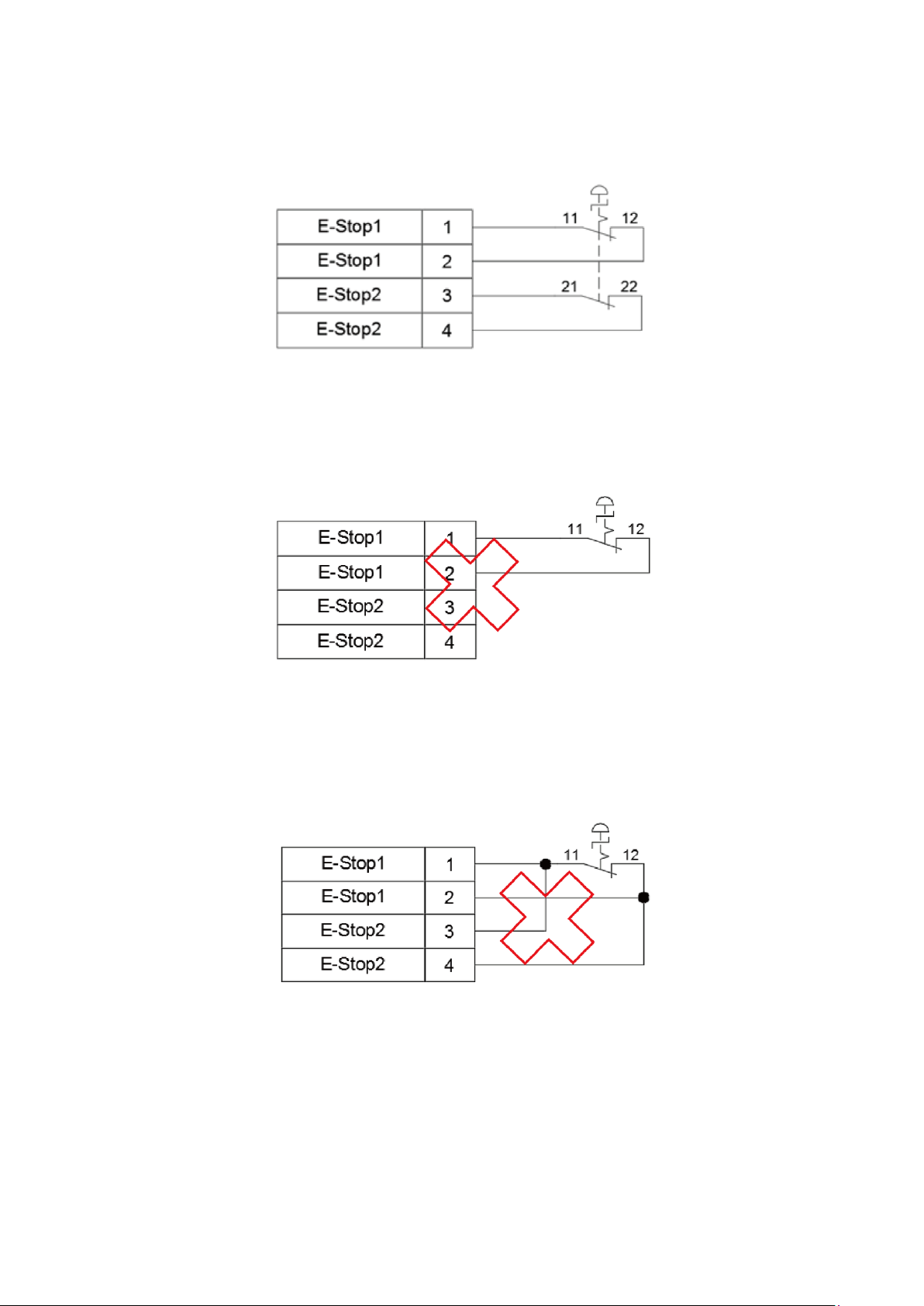
5. Wiring
49
Figure 5.16 shows a correct wiring example for a single Emergency Stop button.
Figure 5.16 Wiring example for a single Emergency Stop button
Figure 5.17 shows the incorrect wiring method when connecting only one Emergency Stop button NC
contact. This wiring method is wrong and causes continuous system errors.
Figure 5.17 Incorrect wiring for a single NC emergency stop
Figure 5.18 shows the incorrect wiring method when using only one Emergency Stop button NC and the
safety signal is connected. This wiring method is wrong. Do not use this wiring method. It results in a
decreased safety level for the entire system.
Figure 5.18 Incorrect wiring for a single NC emergency stop with the safety signal connected
Safety
Emergency Stop
Safety
Emergency Stop
afetyS
Emergency Stop
Page 51

DRV70L/90L Series Manual
50
When connecting multiple Emergency Stop buttons, wire them according to Figure 5.19. Place the
Emergency Stop button so that a worker can quickly press the button to stop the robot.
Figure 5.19 Wiring example for multiple Emergency Stop buttons
Pins 5–8 of the safety connector are the safety protection contacts. You can install safety equipment
such as railings, safety gratings, pressure pads or laser scanners according to your application. Figure
5.20 shows the wiring for multiple safety protection devices. Refer to the safety protection construction
and installation descriptions in Section 4.2 for the installation requirements.
When using safety protection railings, connect the A contact (normal open contact) of the railing signal
to Pins5–8. When the railing is properly closed, the NO contact changes to a NC contact. When the
railing is opened and workers are about to enter the range of the robot, the NC contact changes to an
NO contact. At this time, the power from the DCV controller to the robot is disconnected to ensure that
the workers entering the robot range are safe. When using safety protection gratings, pressure pads or
laser scanners, connect the contact (normal close contact) safety device signal to Pins 5–8. When
these signals are not triggered by workers, they stay as NC contacts. When workers touch the gratings,
step on the pressure pads or enter the scanning area of the laser scanners, the NC contact changes to
an NO contact. At this time, the power from the DCV controller to the robot is disconnected to ensure
that the workers entering the robot range are safe.
Figure 5.20 Wiring diagram for multiple safety protection devices
Figure 5.21 shows that for safety protection, you can install safety lock switches on the railings to ensure
that the safety door closes properly.
Figure 5.21 Safety door switch installation
Emergency Stop 1
Emergency Stop 2
Emergency Stop 3
Safety
Fence Interlock 1
Fence Interlock 2
Fence Interlock 3
Page 52
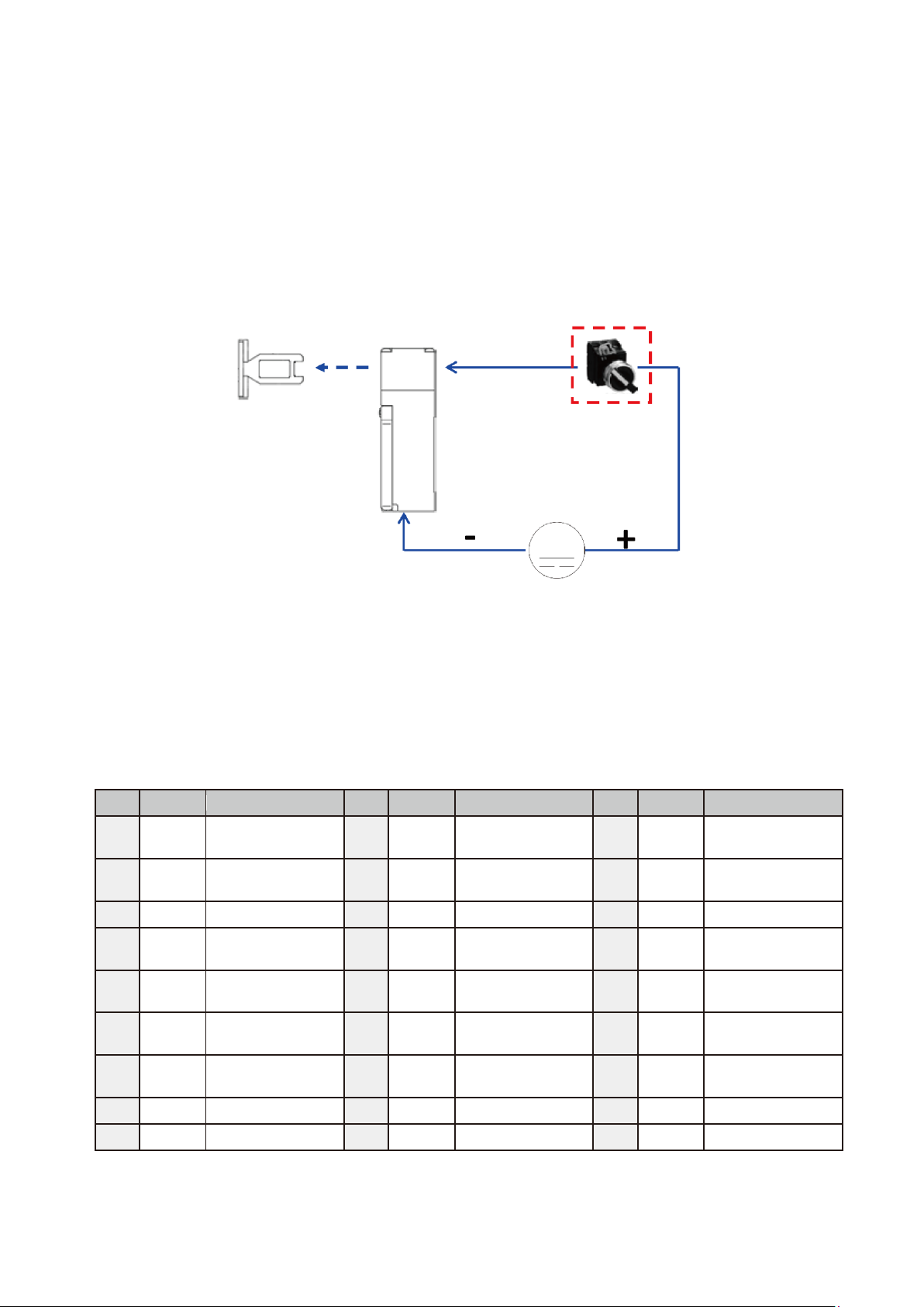
5. Wiring
51
A safer practice is to use electromagnetic safety door switches so that when the safety door is closed,
the safety switch generates a magnetic force to keep the door lock bolt securely in place. This prevents
workers from accidentally opening the door and entering the railing, and protects them from danger.
You can install the power switch for the electromagnetic safety door lock inside the railing so that when
workers are accidentally trapped inside the railing, they can turn off the power switch to release the
electromagnetic safety door. Figure 5.22 shows the installation method.
Figure 5.22 Electromagnetic safety switch wiring
5.2.7 System. DI/O
The DCV controller has a standard D-Sub 25-Pin/Female Connector. The System DI/O connector
provides seven input points and eight output points to communicate with the upper controller (such as a
PLC). Table 5.3 lists the pin definitions.
Table 5.3 System DI/O Pin Definitions
PIN
DI/O
NAME
PIN
DI/O
NAME
PIN
DI/O
NAME
1
DI2
Function Pause
2
DI3
Function Pause
Release
3
DI4
Operation Mode
Selection 1
4
DI5
Operation Mode
Selection 2
5
DI6
Run/Stop Selection
1
6
DI7
Run/Stop Selection
2
7
DI8
Alarm Release
8
+DO1
Alarm Status
9
-DO1
Alarm Status
10
+DO2
Servo Status
11
-DO2
Servo Status
12
+DO3
Robot Position
Status
13
-DO3
Robot Position
Status
14
+DO4
Function Pause
Status
15
-DO4
Function Pause
Status
16
+DO5
Project Run Status
1
17
-DO5
Project Run Status
1
18
+DO6
Project Run Status
2
19
-DO6
Project Run Status
2
20
+DO7
Controller Ready
21
-DO7
Controller Ready
22
+DO8
Reserved
23
-DO8
Reserved
24
25
Safety door lock power
switch installed inside
the railing
Page 53

DRV70L/90L Series Manual
52
The system input signal DI has seven inputs Pins 1–7, and has built-in NPN wiring.
Connect the input signal DI using a button or selection switch to the DC output connector Pin 2 (N24G)
on the DCV controller interface.
Figure 5.23 shows the locations of the system DI/O connector and DC output connector.
Figure 5.23 System .DIO and DC output connector locations
Figure 5.24 shows the wiring method for the input signal DI.
Figure 5.24 Input signal DI wiring
Notes:
1. Use the All System. NPN (sink) connection for all DI signals.
2. The DCV controller DC output connector provides N24G power. Do not connect the System. DI
signal to any other power source to prevent interference with the signal or damage to the DI contact.
3. When the transmitted DI signal is live or when transmitting the signal from the upper controller to the
DI, execute the signal action through a relay or coupler.
Page 54

5. Wiring
53
The system output signal DO has eight outputs Pins 8–23, and the output method can be NPN or PNP.
You can choose whether the output voltage signal is the DCV controller voltage output or the upper
controller voltage output.
Figure 5.25 shows the NPN wiring method when using the DCV controller voltage output as the
output voltage signal.
Figure 5.25 System DO DCV controller voltage output NPN wiring
Figure 5.26 shows the PNP wiring method.
Figure 5.26 System DO controller voltage output NPN wiring
Figure 5.27 shows the mixed NPN and PNP wiring method.
This figure uses PNP output wiring for the lamp and NPN output wiring for the relay.
Figure 5.27 System DO DCV controller voltage mixed output wiring
System Dl/O
onnectorDC Output c
Lamp
System Dl/O
DC Output connector
Lamp
Relay
System Dl/O
DC Output connector
Lamp
Relay
Relay
Page 55

DRV70L/90L Series Manual
54
Figure 5.28 shows the NPN wiring method when the selected output voltage signal is the upper
controller voltage output.
Figure 5.28 System DO upper controller voltage output NPN wiring
Figure 5.29 shows the PNP wiring method.
Figure 5.29 System DO upper controller voltage output PNP wiring
Figure 5.30 shows the upper controller mixed NPN and PNP wiring method.
This figure uses PNP output wiring for the lamp and NPN output wiring for the relay.
Figure 5.30 System DO upper controller voltage mixed output wiring
Notes
1. Each DO output point can supply a maximum output of 40 mA. To activate a heavier current load,
execute the action through a relay.
2. Do not connect AC power to the DO output point to prevent damage to the DCV controller.
System Dl/O
Upper Controller
Lamp
Relay
System Dl/O
Upper Controller
Lamp
Relay
System Dl/O
Upper Controller
Lamp
Relay
Page 56

5. Wiring
55
Description of DI/O Input, Output Pin Functions
DI2 Function Pause
Function Pause puts the robot in a paused status. The robot can continue its action when the
paused state ends.
Notes
1. Do not connect any safety protection device signals (such as railing and gratings) to this contact to
bypass the safety signal in the safety connector. Doing so causes great danger to the workers when
they enter the moving range of the robot.
2. If you bypass the safety signal in the safety connector, our company will not be responsible for any
consequences.
DI3 Function Pause Release
Refer to the DROE Manual for details of this function.
DI4, DI5 Operation Mode Selection 1, 2
Table 5.4 lists the operation mode selections (Auto, T1 25% and T2 100%).
Table 5.4 Operation Mode Selection
Function
DI4
DI5
Auto
0
1
T1 25%
1
0
T2 100%
1
1
Auto Mode
Select Auto mode to automatically execute the robot program. You cannot use the handheld
teaching pendant to perform operations in Auto mode.
Verify that all workers are clear of the robot operation range before executing automatic operations
in Auto mode.
Run the robot at a lower speed the first time you execute automatic operation in Auto Mode. You can
proceed with high-speed operation after you confirm that the robot is acting smoothly without any
errors.
The operating speed of the robot is the speed set in the program in Auto mode.
You can run only the program currently selected by the DROE in Auto mode.
Page 57

DRV70L/90L Series Manual
56
T1 25% Mode
The combined JOG speed of the robot is less than 250 mm/s in T1 25% mode.
If the combined speed is over 250 mm/s, the DCV controller automatically forces the robot to run at
250 mm/s.
You can use the handheld teaching pendant/DROE to execute robot operations in T1 25% mode,
but you cannot use DI6 and DI7 to execute program Run/Pause/Stop.
T1 25% mode is limited to JOG teaching, and you cannot stop the robot when Function Pause is
triggered.
T2 100% Mode
The combined JOG speed of the robot is less than 2000 mm/s in T1 100% mode.
If the combined speed is over 2000 mm/s, the DCV controller automatically forces the robot to run at
2000 mm/s.
You can use the handheld teaching pendant/DROE to execute robot operations in T1 100% mode,
but you cannot use DI/O to execute program Run/Pause/Stop.
The Function Pause triggering is active and you can use it to stop the robot from operating in T1
100% mode.
DI6, DI7 Run/Stop Selection 1, 2
Table 5.5 lists the Run/Pause/Stop selections (PAUSE, STOP and RUN).
Table 5.5 Run/Pause/Stop Selections
Function
DI6
DI7
PAUSE
0
1
STOP
1
0
RUN
1
1
Auto Mode
When DI6, DI7 signals are high, the DCV controller runs the program.
The DI6 and DI7 signals must be in the ON status for 500 msec in order to run the program with DI6
and DI7.
To stop the robot program, change the DI6 signal to High and DI7 to Low for 500 msec. The DCV
controller stops program execution and the robot immediately.
If you need to suspend robot operation while running the program, change the DI6 signal to Low and
DI7 to High for 500 msec. The robot completes running the program and then stops. To continue
running the program, change the DI6 and DI7 signals to High and for 500 msec. The robot then
continues running the paused program.
Page 58

5. Wiring
57
DI8 Alarm Release
If an error occurs in the robot or the DCV controller, the DCV controller releases the error signal
contact.
The signal must be maintained at the ON status for 200 msec to clear the error.
Refer to the software manual for the list of errors and troubleshooting methods.
DO1 Alarm Status
If an error occurs in the robot or the DCV controller, the Alarm signal changes to ON.
If there is no error in the robot or the DCV controller, the Alarm signal changes to OFF.
DO2 Servo Status
When all axes of the drive are Servo On, DO2 continuously outputs a signal until Servo Off.
DO3 Robot In-place Status
When the robot is moving, the machine continuously outputs a DO3 signal. When the robot stops
moving, the machine stops outputting a DO3 signal.
DO4 Function Pause Status
Refer to the DROE Manual for details of this function.
DO5, DO6 Project Running Status 1, 2
DO5 and DO6 output the corresponding status according to the project running status, as shown in
Table 5.6.
Table 5.6 Project Running Status Output
Function
DO5
DO6
PAUSE
0
1
STOP
1
0
RUN
1
1
DO7 Controller is Ready
After the DCV controller is ready, DO7 is ON.
DO8 Reserved
Reserved by Delta.
Page 59
DRV70L/90L Series Manual
58
5.2.8 User. DI/O
The DCV controller has a standard D-Sub 50-Pin/Female/3-row connector. This connector provides 24
user-defined input points and 12 user-defined output points.
Table 5.7 lists the pin definitions.
Table 5.7 User. DI/O Pin Definitions
PIN
DI/O
NAME
PIN
DI/O
NAME
PIN
DI/O
NAME
1
DI1
User. DI1
2
DI2
User. DI2
3
DI3
User. DI3
4
DI4
User. DI4
5
DI5
User. DI5
6
DI6
User. DI6
7
DI7
User. DI7
8
DI8
User. DI8
9
DI9
User. DI9
10
DI10
User. DI10
11
DI11
User. DI11
12
DI12
User. DI12
13
DI13
User. DI13
14
DI14
User. DI14
15
DI15
User. DI15
16
DI16
User. DI16
17
DI17
User. DI17
18
DI18
User. DI18
19
DI19
User. DI19
20
DI20
User. DI20
21
DI21
User. DI21
22
DI22
User. DI22
23
DI23
User. DI23
24
DI24
User. DI24
25
+DO1
+User. DO1
26
-DO1
-User. DO1
27
+DO2
+User. DO2
28
-DO2
-User. DO2
29
+DO3
+User. DO3
30
-DO3
-User. DO3
31
+DO4
+User. DO4
32
-DO4
-User. DO4
33
+DO5
+User. DO5
34
-DO5
-User. DO5
35
+DO6
+User. DO6
36
-DO6
-User. DO6
37
+DO7
+User. DO7
38
-DO7
-User. DO7
39
+DO8
+User. DO8
40
-DO8
-User. DO8
41
+DO9
+User. DO9
42
-DO9
-User. DO9
43
+DO10
+User. DO10
44
-DO10
-User. DO10
45
+DO11
+User. DO11
46
-DO11
-User. DO11
47
+DO12
+User. DO12
48
-DO12
-User. DO12
49
50
COM
DI_COM
Page 60
5. Wiring
59
Figure 5.31 shows the User. DI/O connector location.
Figure 5.31 User. DIO connector location
The user-defined input signal D1 includes a total of 24 points (Pins 1–24). You can choose either NPN
or PNP wiring.
Using the power from the DCV controller for the input signal DI
Figure 5.32 shows the NPN wiring method. Connect the DI COM (Pin 50) of User. DI/O (D Sub-50P)
to P24V (Pin 1) of the DC output, and connect the output signals such as buttons, switches and
sensors to DI.
Figure 5.32 NPN wiring when the input signal DI uses power from the DCV controller
Figure 5.33 shows the PNP wiring method. Connect DI COM (Pin 50) of User. DI/O (D Sub-50P) to
N24G (Pin 2) of the DC output, and connect the output signals such as buttons, switches and
sensors to DI.
Figure 5.33 PNP wiring when the input signal DI uses power from the DCV controller
User. DI
DC Output connector
User. DI
DC Output connector
Page 61
DRV70L/90L Series Manual
60
Note:
1. The DCV controller DC output connector provides N24G power. Do not connect the System. DI
signal to any other power source to prevent interference with the signal cause damage to the DI
contact.
Figure 5.34 shows the wiring method when connecting the input signal DI directly to the upper controller
using NPN wiring.
Figure 5.34 Input signal DI connected to the upper controller using NPN connection
Figure 5.35 shows the wiring method when connecting the input signal DI directly to the upper controller
using PNP wiring.
Figure 5.35 Input signal DI connected to the upper controller using PNP connection
The output signal DO includes a total of 24 output points from Pin 25–48, and the output method can be
NPN or PNP.
You can use either output voltage signal from the DCV controller voltage output or the upper controller
voltage output.
Figure 5.36 shows the NPN wiring method when using the DCV controller voltage output as the
output voltage signal.
Figure 5.36 User. DO controller voltage output NPN wiring
User. DI
Upper Controller
User. DI
Upper Controller
User. DO
DC Output connector
Lamp
Relay
Page 62

5. Wiring
61
Notes: When connecting an inductive load (such as a solenoid valve) to the output DO signal, do not
connect the DO signal directly to the inductive load. It is best to connect through a relay to protect
the DO output contact so that power surges generated when the inductive load switches between
ON and OFF do not damage the DO output contact. If you must connect the inductive load directly,
connect a flywheel diode to the inductive load using a parallel connection to protect the DO
contact.
Figure 5.37 shows the PNP wiring method.
Figure 5.37 PNP wiring when the input signal DI uses power from the Controller
Figure 5.38 shows the mixed NPN and PNP wiring method using PNP output wiring for the lamp and
NPN output wiring for the relay.
Figure 5.38 User. DO DCV controller voltage mixed output wiring
Figure 5.39 shows the NPN wring method when using the upper controller voltage output as the output
voltage signal.
Figure 5.39 User. DO upper controller voltage output NPN wiring
User. DO
DC Output connector
Lamp
Relay
User. DO
t connectorDC Outpu
Lamp
Relay
User. Do
Upper Controller
Lamp
Relay
Page 63

DRV70L/90L Series Manual
62
Figure 5.40 shows the PNP wiring method.
Figure 5.40 User. DO upper controller voltage output PNP wiring
Figure 5.41 shows the upper controller mixed NPN and PNP wiring method using PNP output wiring for
the lamp and NPN output wiring for the relay.
Figure 5.41 User. DO upper controller voltage mixed output wiring
Notes:
1. Each DO output point can supply a maximum of 40 mA. To activate a heavier current load, execute
the action through a relay.
2. Do not connect AC power to the DO output point to prevent damage to the DCV controller.
User. DO
Upper Controller
Lamp
Relay
User. DO
Upper Controller
Lamp
Relay
Page 64

5. Wiring
63
5.2.9 External Encoder
The DCV controller has a Standard D-Sub 37-Pin/Female connector to connect to an external encoder.
Refer to the DROE software manual for details on using this function.
Figure 5.42 shows the location of the encoder connector and Table 5.8 lists the pin definitions.
Figure 5.42 External encoder connector location
Table 5.8 External Encoder Pin Definitions
PIN
NAME
PIN
NAME
PIN
NAME
PIN
NAME
1 Z 2
/Z
3 B 4
/B
5 A 6
/A 7 +5V 8 0V 9
10 11 12 13 14 15 16 17 18 19 20 21 22 23 24 25 26 27 28 29 30 31 32
33 34 35 36 37
Page 65

DRV70L/90L Series Manual
64
5.2.10 Robot Connector
Figure 5.43 shows the location of the robot connector and Figure 5.44 shows the robot connector cable.
The cable connects the robot motor and encoder signals between the robot and DCV controller. Table
5.9 lists the cable pin definitions.
When connecting the robot cable, ensure that the buckles are properly locked in place before turning on
the power. Note the connector directions: both ends of the connector have foolproof designs so forcing
the connection the wrong way will damage the connector and the equipment. Do not increase the cable
length or you may cause problems such as weakening the signals and causing the equipment to
malfunction.
Figure 5.43 Robot cable connector location
Figure 5.44 Robot cable
Table 5.9 Robot Cable Pin Definitions
PIN
Module 1
12Pos
PIN
Module 2
12Pos
PIN
Module 3
12Pos
PIN
Module 4
12Pos
PIN
Module 4
12Pos
1
J1-U
1
J3-U
1
J5-U
1
J1-5V
13
J4-5V
2
J1-V
2
J3-V
2
J5-V
2
J1-0V
14
J4-0V
3
J1-W
3
J3-W
3
J5-W
3
+J1-T
15
+J4-T
4
J1-Ground
4
J3-Ground
4
J5-Ground
4
-J1-T
16
_J4-T
5
+J1-Brk
5
+J3-Brk
5
+J5-Brk
5
J2-5V
17
J5-5V
6
-J1-Brk
6
-J3-Brk
6
-J5-Brk
6
J2-0V
18
J5-0V
7
J2-U
7
J4-U
7
J6-U
7
+J2-T
19
+J5-T
8
J2-V
8
J4-V
8
J6-V
8
-J2-T
20
-J5-T
9
J2-W
9
J2-W
9
J6-W
9
J3-5V
21
J6-5V
10
J2-Ground
10
J4-Ground
10
J6-Ground
10
J3-0V
22
J6-0V
11
+J2-Brk
11
+J4-Brk
11
+J6-Brk
11
+J3-T
23
+J3-T
12
-J2-Brk
12
-J4-Brk
12
-J6-Brk
12
-J3-T
24
-J6-T
Page 66

5. Wiring
65
6. Connecting the Controller to
the Robot
6.1 Robot Signal Connector ............................................................... 67
6.2 Wiring of the Robot’s Built-in Solenoid Valve ............................... 68
Page 67
DRV70L/90L Series Manual
66
6. Connecting the Controller to the Robot
This chapter shows how to connect the DCV controller to the robot.
Correctly wire the DCV controller to the robot according to the descriptions in
the manual.
Turn off the power during wiring to prevent a danger of electrical shocks.
Wait 10 minutes after turning off the DCV controller power before you perform
any wiring because there is residual voltage in the DCV controller that has not
yet been fully discharged.
Only workers with related licenses can perform wiring operations. Workers
without related licenses shall not perform wiring operations.
Before entering the safety railing around the robot, turn off the DCV controller
power and place a warning sign on the safety railing. Lock the safety railing
open to prevent it from being closed and to prevent other dangers.
Workers without related licenses shall not perform wiring operations.
Do not modify any circuits in the robot; our company is not responsible for any
danger that occurs as a result of such modifications.
Do not modify any air pipes within the robot to prevent bent air pipes or other
damages.
Page 68

6. Connecting the Controller to the Robot
67
6.1 Robot Signal Connector
The DRV70L/90L Series robot has a 12-Pos circular connector located at the J4 axis wrist for connect
signals.
You can use this 12-Pos connector for sensor signals from sensors you install on the TCP terminal.
The 12-Pos connector at the robot’s J4 axis wrist connects to pins 1–12 of the 24-Pos circular connector
located on the back of the robot base, as shown in Figure 6.1.
Notes:
1. This 12-Pos connector is only for sensors installed on the TCP terminal. It cannot drive loads
exceeding 0.5 A.
2. The maximum current allowed for each of the 12-Pos in the connector is 0.5 A when used to
connect external indicators or used as an output signal.
Figure 6.1 Internal wiring of the robot 12-Pos signal connector
Page 69
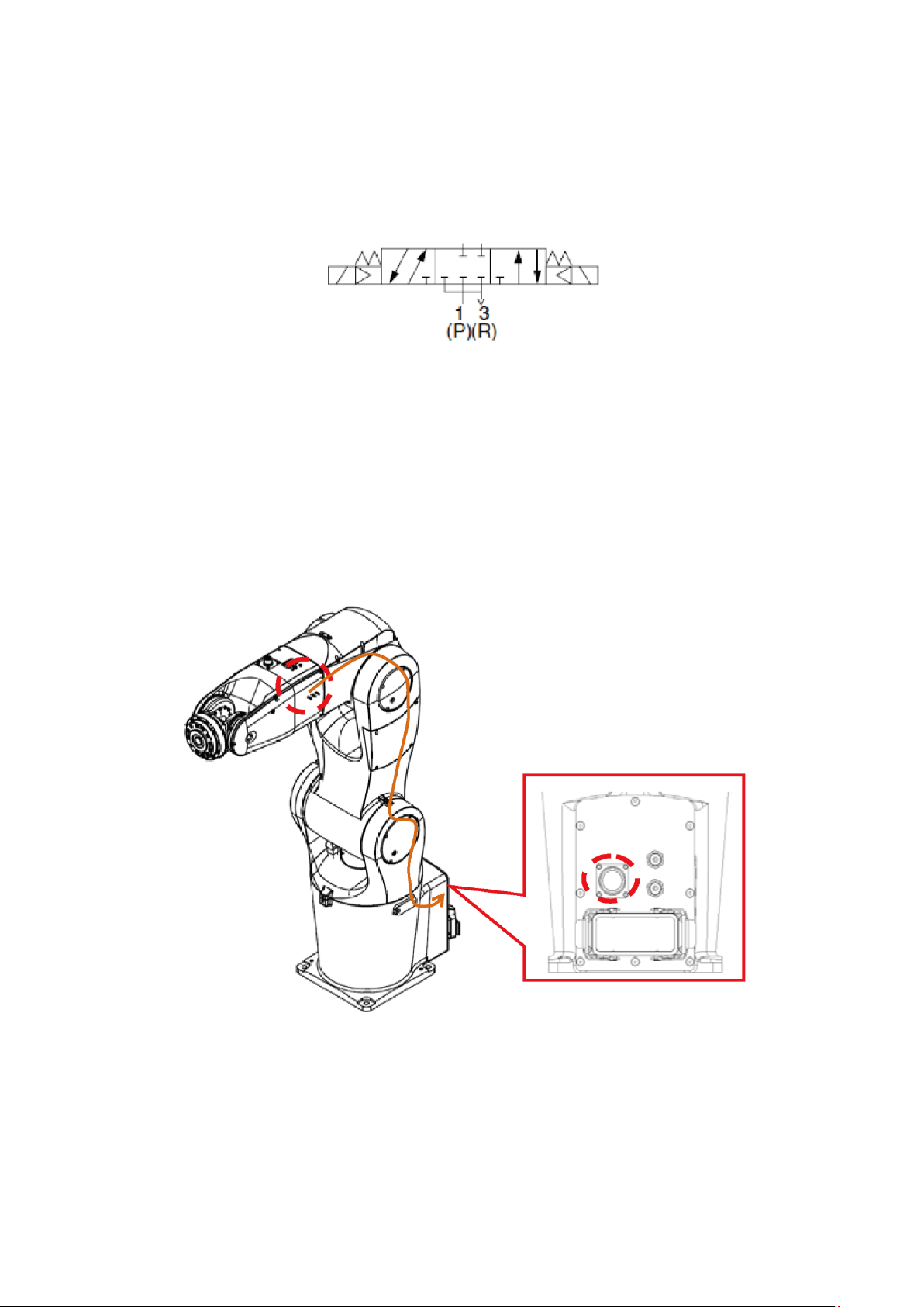
DRV70L/90L Series Manual
68
6.2 Wiring the Robot’s Built-in Solenoid Valve
Figure 6.2 shows the location of the DRV70L/90L series robot three 24 VDC, five-port, three-position
central blocking solenoid valves inside the J4 axis robot arms for your use.
Figure 6.2 Location of solenoid valve inside the robot
The driving coils for these three sets of solenoid valves are 24 VDC. The circuit enters from inside the
robot’s J5 axis and connects to pins 13–24 of the 24-Pos circular connector located in back of the robot
base, as shown in Figure 6.3 below.
Notes:
1. Do not connect AC power to pins 13-24 of the 24-Pos connector on the robot base. The driving coils
of these three sets of solenoid valves are 24 VDC.
2. The power of the solenoid valve coil is only 0.35 W. The current needed to drive one side of a single
solenoid valve is 15 mA.
Figure 6.3 The robot’s built-in solenoid valve wiring location
Page 70
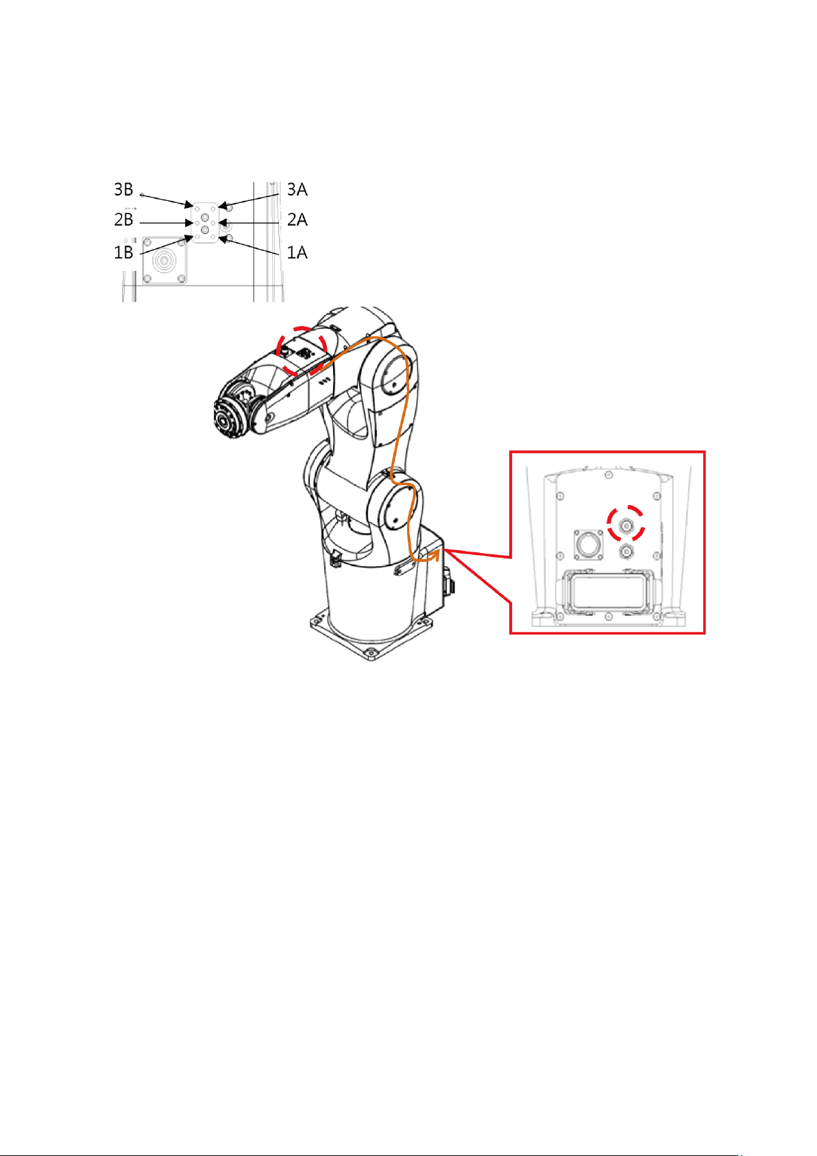
6. Connecting the Controller to the Robot
69
The robot includes two ø6 air pipe connectors on the back of the base of the robot for your use. One air
pipe is connected to the solenoid valve inside the robot, and the other is connected on the top of the J4
axis for your use. Figure 6.4 shows the robot’s first set of internal air pipe location.
Figure 6.4 The robot’s built-in internal air pipe location
Page 71
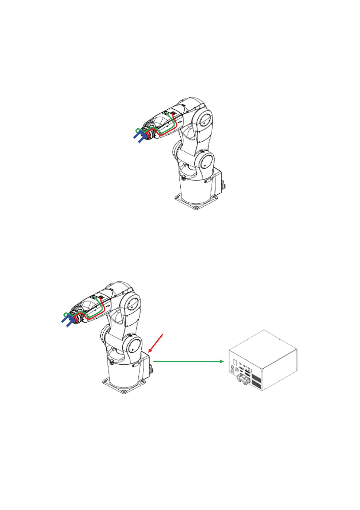
DRV70L/90L Series Manual
70
Figure 6.5 shows an air pipe and sensor wiring example using a clasping jaw on the robot’s TCP terminal.
The green cable is the clasping jaw sensor signal cable and the red cable is the clasping jaw air pipe.
You can run the clasping jaw air pipe and sensor cable directly to the J4 arm using a hollow cable running
from the TCP terminal of the robot; this method prevents the air pipe or cable from rupturing when the
robot rotates the J6 axis.
Figure 6.5 TCP Terminal air pipe and sensor wiring example
You can connect the factory terminal air source to the ø6 air pipe connector at the robot’s base to provide
an air source for the solenoid valve inside the robot. You can also connect the clasping jaw sensor signal
cable and solenoid valve coil signal cable to the User. DI/O connector on the DCV robot controller, or to
the upper controller terminal using the 24-Pos circular connector at the base of the robot, as shown in
Figure 6.6.
Figure 6.6 Robot clasping jaw signal and DCV controller connection
Factory terminal
air source input
Clasping jaw sensor
and solenoid valve
signal cable
Page 72

6. Connecting the Controller to the Robot
71
Note:
1. The robot arm contains only pneumatic system connection pipelines. The system integrators shall
install the final actuator and pneumatic system according to EN ISO 4414.
2. Table 6.1 lists the definitions for the 24-Pos connector at the base of the robot.
Table 6.1 Robot Signal Connector Pin Definitions
PIN
NAME
PIN
NAME
PIN
NAME
1
12Pos-1
2
12Pos-2
3
12Pos-3
4
12Pos-4
5
12Pos-5
6
12Pos-6
7
12Pos-7
8
12Pos-8
9
12Pos-9
10
12Pos-10
11
12Pos-11
12
12Pos-12
13
+Solenoid-1A
14
-Solenoid-1A
15
+Solenoid-2A
16
-Solenoid-2A
17
+Solenoid-3A
18
-Solenoid-3A
19
+Solenoid-1B
20
-Solenoid-1B
21
+Solenoid-2B
22
-Solenoid-2B
23
+Solenoid-3B
24
-Solenoid-3B
3. The solenoid valve is 24 VDC. Do not connect any AC voltages or any DC voltages that exceed this
specification.
4. The solenoid valve coil power is only 0.35 W.
5. The DCV controller DO output uses a transistor. It can drive the solenoid valve directly, but to
prevent damaging the DCV controller DO contact or the solenoid valve due to a short circuit, it is
recommended that you drive the solenoid valve through a relay. Figure 6.7 shows the wiring
example.
6. The solenoid valve is a dual-coil type. Do not transmit power to the A and B terminals
simultaneously when driving the same solenoid valve because it causes the solenoid valve iron core
to be attracted, and the valve is unable to switch successfully.
Figure 6.7 Wiring example for driving the solenoid valve
User DO
Robot Signal
connector
DC Output
connector
Page 73

72
7. Quickstart Robot Wiring
Page 74

7. Quickstart Robot Wiring
73
7. Quickstart Robot Wiring
This chapter provides the steps to quickly wire the robot. You must install safety protection devices before
operation in order to ensure worker safety. Refer to safety protection equipment descriptions in Chapter
4.
Correctly wire the robot and DCV controller according to the instructions in
this manual.
Install safety protection devices around the robot, such as railings, safety
gratings, pressure pads or laser scanners to guarantee the safety of the
workers.
Turn off the power before wiring to prevent a danger of electrical shocks.
Wait 10 minutes after turning off the DCV controller power because there is
residual voltage in the DCV controller that has not yet been fully discharged.
Only workers with related licenses shall perform wiring operations. Workers
without related licenses shall not perform wiring operations.
You must install one or more Emergency Stop buttons before working with
the robot. Emergency Stop buttons must be installed in a visible location
where they can be quickly pressed.
Keep all workers away from the working range of the robot in order to avoid
danger before operating the robot.
Workers without related licenses shall not perform wiring operations.
Do not bypass the safety protection system. The safety protection system
includes the emergency stop signal and signals from safety equipment such
as railings.
The emergency stop signal and railing signal are no-voltage contact signals.
Do not connect any AC or DC power to prevent damage to the DCV
controller.
Do not modify any wiring inside the DCV controller. Our company is not
responsible for any DCV controller malfunctions or damage resulting from
doing so.
Page 75

DRV70L/90L Series Manual
74
(1) Complete the construction of the safety protection devices. Refer to the safety protection
descriptions in Chapter 4 and the wiring in Chapter 5 for details.
(2) Correctly connect the Emergency Stop button and safety signals, as shown in Figure 7.1.
Figure 7.1 Emergency Stop button and safety signal wiring
(3) Correctly connect the handheld teaching pendant to the DCV controller, as shown in Figure 7.2.
If you did not purchase the optional handheld teaching pendant, install the teaching pendant shortcircuit connector on the DCV controller. The teaching pendant short-circuit connector is included in
the accessory pack.
Figure 7.2 Handheld teaching pendant connection location
Safety
Emergency Stop
Fence Interlock
Handheld teaching pendant
Page 76
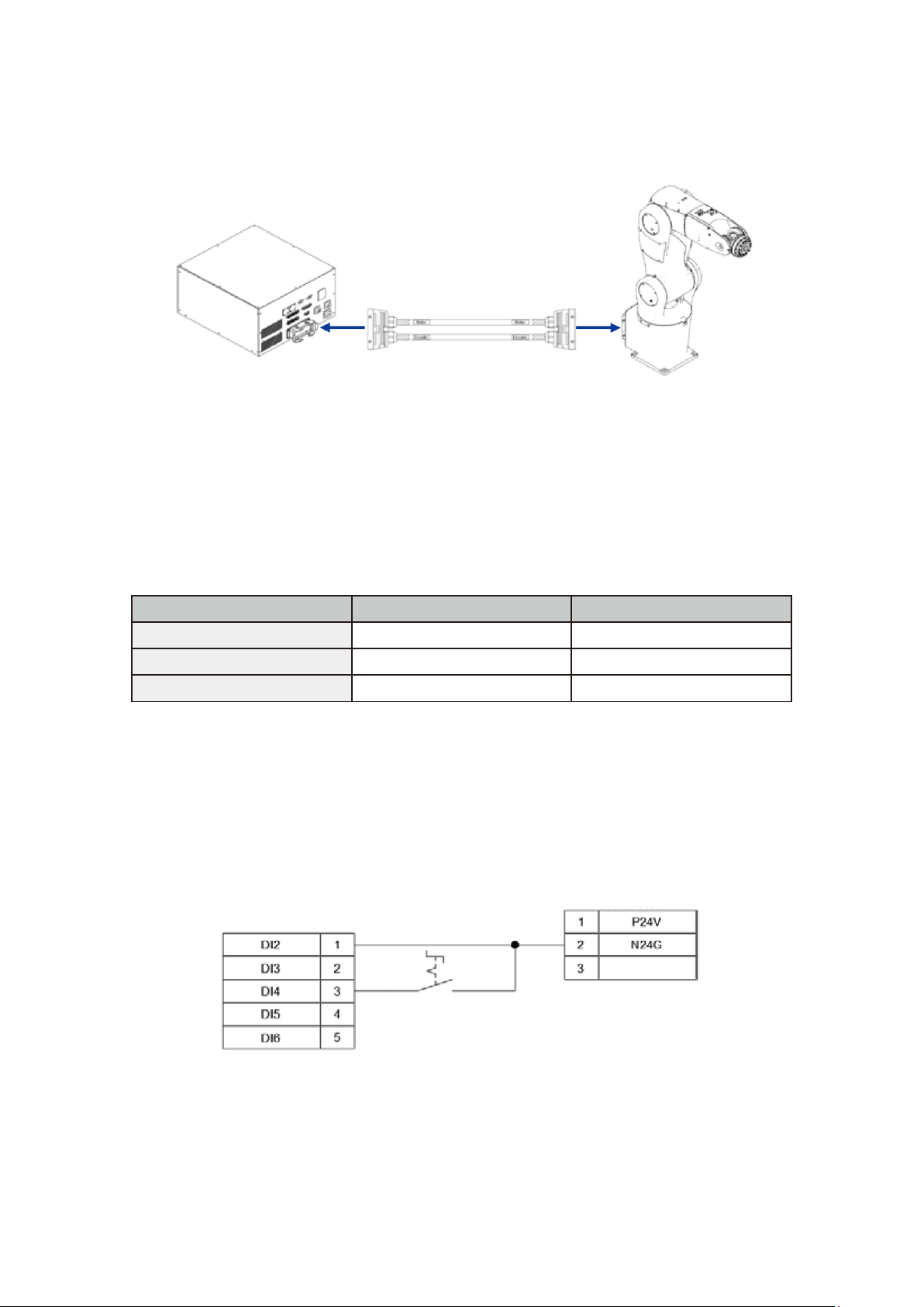
7. Quickstart Robot Wiring
75
(4) Correctly connect the cables between the robot and DCV controller, and lock them in place, as
shown in Figure 7.3.
Figure 7.3 Robot and DCV controller cable connection
(5) Mode Selection Wiring
DI4, DI5 Operation Mode Selection 1, 2
Table 7.1 lists the operation modes (Auto, T1 25% and T2 100%). During initial operations when workers
are unfamiliar with the robot, use the T1 25% mode to prevent danger to the workers or damage to the
machine.
Table 7.1 Operation Mode Selection
Function
DI4
DI5
Auto
0
1
T1 25%
1
0
T2 100%
1
1
Figure 7.4 shows how to wire the System DI/O signals. Short-circuit the DI2 signal (Function Pause) and
N24G on the DC output connector. Use a two-stage selection switch that requires a key to connect the
DI4 signal.
Notes:
1. You must be able to remove the selection switch key from any setting.
2. The supervisor should keep the key to ensure worker safety and to protect against misuse and
unauthorized operation.
Figure 7.4 Quickstart DI wiring example
System DI/O
DC Output connector
Page 77

DRV70L/90L Series Manual
76
(6) Connecting Input Power
Use only single-phase 220–230 Vac, 50/60 Hz input power. The input power must be properly grounded,
as shown in Figure 7.5.
L and N are power cables and E is the ground cable.
Figure 7.5 Quickstart wiring power wiring example
(7) Turn on the power to the DCV controller and switch the power switch on the DCV controller from
OFF to ON, as shown in Figure 7.6.
Figure 7.6 Quickstart wiring power switch ON
(8) Refer to the DROE software manual for robot operations.
Page 78

77
8. Maintenance
8.1 Fan Filter Cleaning ....................................................................... 78
Page 79

DRV70L/90L Series Manual
78
8. Maintenance
Implement maintenance and inspections according to the maintenance table to prolong the DCV
controller life.
Do not maintain or inspect the DCV controller and robot while power is ON to
prevent electrical shocks or injuries to the workers.
Place notices by the power switch and robot not to turn on the power when
maintaining and repairing the robot.
Do not open the DCV controller within 10 minutes of powering it off to prevent
electrical shocks from residual voltage in the DCV controller.
Only properly trained electrical technicians can install, wire, service and
maintain this robot.
Make sure foreign objects do not get attached or enter the DCV controller or
robot when performing maintenance or inspection.
8.1 Fan Filter Cleaning
Regularly clean the two DCV controller ventilation filters to maintain the airflow in the DCV controller. If
the filters become blocked, the temperature will increase, resulting in DCV controller malfunctions.
Cleaning Cycle
At oil and steam-free locations: clean once every six months.
At locations subject to oil and steam: clean once every two weeks.
If the DCV controller is placed outside the robot enclosure: clean once every two weeks.
Figure 8.1 shows the locations of the DCV controller ventilation filters. One is located on the front of the
DCV controller and the other is located on the side of the DCV controller.
Figure 8.1 Controller ventilation filter locations
Notes:
1. When cleaning, do not aim an air gun directly at the filter to clean it. If there is water inside the air
gun, it will cause damage to the DCV controller components, or cause a danger of short circuiting
when the power is turned on.
2. The correct cleaning method is to remove the filters and then clean them. Replace the filters into the
DCV controller after cleaning is complete.
Page 80

8. Maintenance
79
9. Accessories
9.1 Controller Accessory Pack ............................................................ 81
9.2 Optional Controller Peripheral Accessories .................................. 82
9.2.1 EMI Peripheral Accessories .............................................. 82
9.2.2 Extension Cord Accessories .............................................. 83
9.2.3 DI/O Expansion, Driver Accessories .................................. 83
9.2.4 Handheld Teaching Pendant ............................................. 87
9.2.5 Robot Cable ...................................................................... 87
Page 81

DRV70L/90L Series Manual
80
9. Accessories
This chapter describes the optional accessories for the DCV controller. You can purchase them as required.
Turn the power off before installing the optional accessories to prevent
damage to the DCV controller or injuries and other danger to the workers.
Wait 10 minutes after you turn off the power to the DCV controller before you
open the DCV controller or perform any wiring because there is residual
voltage in the DCV controller that has not yet been fully discharged.
Only workers with related wiring experience should perform wiring operations.
Incorrect wiring can damage the DCV controller or cause injuries and other
danger to the workers.
Do not use another brand of connectors to prevent incorrect connections or
poor contact due to incompatible connectors.
Do not modify the connectors on the DCV controller. Our company is not
responsible for any malfunctions or damage that result from doing so.
Page 82
9. Accessories
81
9.1 Controller Accessory Pack
The robot is a semi-finished product and the robot system must be correctly installed and integrated with
safety protection devices according to your applications. Accessories are located in the accessory pack
included in each DCV controller. These accessory can assist you in installing and performing the integrated
wiring with their upper controller (such as a PLC), as well as the peripheral system and safety protection
devices.
Table 9.1 lists the contents of the DCV controller’s accessory pack. An accessory pack is included when
you initially purchase a DCV controller. If you need additional accessory packs, you can purchase them
separately.
Table 9.1 Controller Accessory Pack Contents
Controller Accessory Pack (3534538100)
Item
Number
Name
Specifications
Function
Quantity
1
D-type Connector
9-Pin, male, welded
Use for connecting RS-232/485 on
the controller
1
2
D-type Connector
Cover
Iron case, outlet aperture 8mm
D-type connector for 9-pin use
1
3
D-type Connector
25-Pin, male, welded
Use for connecting System.DI/O on
the controller
1
4
D-type Connector
Cover
Iron case, outlet aperture 10 mm
D-type connector for 25-pin use
1
5
D-type Connector
37-Pin, male, welded
Use for connecting the external
encoder on the controller
1
6
D-type Connector
Cover
Iron case, outlet aperture 12 mm
D-type connector for 37-pin use
1
7
D-type Connector
50-Pin, male, welded, three-rows
Use for connecting User. DI/O on the
controller
1
8
D-type Connector
Cover
Iron case, outlet aperture 13 mm
D-type connector for 50-pin use
1
9
Circular Connector
3-Pos, male, welded
Use for connecting DC power on the
controller
1
10
Cable Clamp
Outlet aperture 8mm
DC Power and safety connector cable
clamp
2
11
Circular Connector
8-Pos, male, welded
Use for connecting the safety signal to
the controller
1
12
Circular Connector
12-Pos, male, welded
Use for connecting the signal
connector on the J5 arm of the robot
1
13
Circular Connector
24-Pos, female, welded
Use for connecting the signal
connector on the base of the robot
1
14
Cable Clamp
Outlet aperture 10 mm
Cable clamp for connecting the signal
connector on the robot base
1
15
Circular Connector
17-Pos
Use the short-circuit connector when
the controller’s handheld teaching
pendant is not connected
1
Page 83

DRV70L/90L Series Manual
82
9.2 Optional Controller Peripheral Accessories
This section describes the peripheral accessories for integrating the various DCV robot controller peripheral
systems. You can purchase and use them according to your applications.
9.2.1 EMI Peripheral Accessories
It is recommended that you purchase appropriate optional wave filters to prevent the DCV controller from
being affected by interference from surrounding networks and power sources. Figure 9.1 shows the
installation dimensions.
Table 9.2 EMI Accessory Specifications
Item
Number
Name
Specifications
Function
Order Part
Number
1
Wave Filter
115/250 Vac, 16 A, 50/60 Hz
Leakage current: 0.8 mA maximum
Filters noise
1-DPCG516
Figure 9.1 Delta wave filter 16DPCG5-1 dimensions
Page 84

9. Accessories
83
9.2.2 Extension Cord Accessories
We provide optional extension cord accessories if you do not want to perform wiring using the connectors
in the accessory pack described in Section 9.1.
Table 9.3 Extension Cord Accessory Specifications
Item
Number
Name
Specifications
Order Part Number
1
System DI/O Extension Cord
3 meters, non-flexible
3081425800
2
User. DI/O Extension Cord
3 meters, non-flexible
3081425700
3
Safety Extension Cord
3 meters, non-flexible
3081735000
4
Ext.Encoder Extension Cord
3 meters, non-flexible
3081427000
5
RS-232/485 Extension Cord
3 meters, non-flexible
3081427100
6
Robot Arm Signal Extension Cord
5 meters, non-flexible
3081734700
7
Robot Arm Signal Extension Cord
7 meters, non-flexible
3081734800
8
Robot Arm Signal Extension Cord
12 meters, non-flexible
3081734900
Note: Items 1–5 in Table 9.3 are DCV controller terminal extension cords. Items 6–8 are robot terminal
signal extension cords.
9.2.3 DI/O Expansion, Driver Accessories
Figure 9.2 shows the System DI/O extension cord (3081425800) and Table 9.4 lists the cord colors.. You
can connect to peripheral components such as an upper controller, buttons or indicators through these
extension cords.
Figure 9.2 System DI/O Extension Cord (3081425800)
Table 9.4 System DI/O Extension Cord (3081425800) Cord Colors
PIN
DI/O
NAME
Color
PIN
DI/O
NAME
Color
1
DI2
Function Pause
Black
2
DI3
Function Pause Release
Brown
3
DI4
Operation Mode Selection
1
Black
4
DI5
Operation Mode Selection
2
Red
5
DI6
Run/Stop Selection 1
Black
6
DI7
Run/Stop Selection 2
Orange
7
DI8
Alarm Release
Black
8
+DO1
Alarm Status
Yellow
9
-DO1
Alarm Status
Black
10
+DO2
Servo Status
Green
11
-DO2
Servo Status
Black
12
+DO3
Robot Position Status
Blue
13
-DO3
Robot Position Status
Black
14
+DO4
Function Pause Status
Purple
15
-DO4
Function Pause Status
Black
16
+DO5
Project Run Status 1
Gray
17
-DO5
Project Run Status 1
Black
18
+DO6
Project Run Status 2
White
19
-DO6
Project Run Status 2
Brown
20
+DO7
Controller Ready
Red
12
-DO7
Controller Ready
Brown
22
+DO8
Reserved
Orange
23
-DO8
Reserved
Brown
24
25
Page 85

DRV70L/90L Series Manual
84
Figure 9.3 shows the user-defined DI/O extension cord (3081425700), and Table 9.5 lists the cord colors..
You can connect to peripheral components such as an upper controller, buttons or indicators through these
extension cords.
Figure 9.3 User. DI/O Extension Cord (3081425700)
Table 9.5 User. DI/O Extension Cord (3081425700) Cord Colors
PIN
DI/O
NAME
Color
PIN
DI/O
NAME
Color
1
DI1
User. DI1
White
2
DI2
User. DI2
Brown
3
DI3
User. DI3
Green
4
DI4
User. DI4
Yellow
5
DI5
User. DI5
Gray
6
DI6
User. DI6
Pink
7
DI7
User. DI7
Blue
8
DI8
User. DI8
Red
9
DI9
User. DI9
Black
10
DI10
User. DI10
Purple
11
DI11
User. DI11
Gray/Pink
12
DI12
User. DI12
Red/Blue
13
DI13
User. DI13
White/Green
14
DI14
User. DI14
Brown/Green
15
DI15
User. DI15
White/Yellow
16
DI16
User. DI16
Brown/Yellow
17
DI17
User. DI17
White/Gray
18
DI18
User. DI18
Brown/Gray
19
DI19
User. DI19
White/Pink
20
DI20
User. DI20
Brown/Pink
21
DI21
User. DI21
White/Blue
22
DI22
User. DI22
Brown/Blue
23
DI23
User. DI23
White/Red
24
DI24
-User. DI24
Brown/Red
25
+DO1
+User. DO1
White/Black
26
-DO1
-User. DO1
Brown/Black
27
+DO2
+User. DO2
Green/Gray
28
-DO2
-User. DO2
Yellow/Gray
29
+DO3
+User. DO3
Green/Pink
30
-DO3
-User. DO3
Yellow/Pink
31
+DO4
+User. DO4
Green/Blue
32
-DO4
-User. DO4
Yellow/Blue
33
+DO5
+User. DO5
Green/Red
34
-DO5
-User. DO5
Yellow/Red
35
+DO6
+User. DO6
Yellow/Black
36
-DO6
-User. DO6
Green/Black
37
+DO7
+User. DO7
Gray/Blue
38
-DO7
-User. DO7
Pink/Blue
39
+DO8
+User. DO8
Gray/Red
40
-DO8
-User. DO8
Pink/Red
41
+DO9
+User. DO9
Gray/Black
42
-DO9
-User. DO9
Pink/Black
43
+DO10
+User. DO10
Blue/Black
44
-DO10
-User. DO10
Red/Black
45
+DO11
+User. DO11
White
46
-DO11
-User. DO11
Brown
47
+DO12
+User. DO12
Green
48
-DO12
User. DO12
Yellow
49
Gray
50
DICOM
DICOM
Pink
Page 86
9. Accessories
85
Figure 9.4 shoes the safety extension cord (3081735000), and Table 9.6 lists the cord colors. You can
connect to Emergency Stop buttons and safety protection devices installed as part of the integrated safety
system.
Figure 9.4 Safety Extension Cord (3081735000)
Table 9.6 Safety Extension Cord (3081735000) Cable Color
PIN
NAME
Color
PIN
NAME
Color
1
Emergency Stop NC1
Black 2 Emergency Stop NC1
Brown 3 Emergency Stop NC2
Black 4 Emergency Stop NC2
Red 5 Safety Protection NO1
Black 6 Safety Protection NO1
Orange 7 Safety Protection NO2
Black 8 Safety Protection NO2
Yellow
Figure 9.5 shows the Ext.Encoder extension cord (3081427000), and Table 9.7 lists the cord colors. You
can use this extension cord to connect an encoder signal with the A, B and Z phases for fully closed circuit
control or conveyor tracking applications.
Figure 9.5 Ext.Encoder Extension Cord (3081427000)
Table 9.7 Safety Extension Cord (3081735000) Cord Color
PIN
NAME
Color
PIN
NAME
Color
PIN
NAME
Color
1 Z Black 2 /Z
Brown 3 B
Black 4 /B
Red 5 A
Black 6 /A
Orange 7 5V
Black 8 0V
Yellow 9
10
11
12
13
14
15
16
17
18
19
20
21
22
23
24
25
26
27
28
29
30
31
32
33
34
35
36
37
Page 87
DRV70L/90L Series Manual
86
Figure 9.6 shows the RS-232/485 extension cord (3081421000), and Table 9.8 lists the cord colors. You
can use this extension cord to connect communication equipment equipped with RS-232 or RS-485, and
then perform connection, control or data transmission with the DCV controller.
Figure 9.6 RS-232/485 Extension Cord (3081427100)
Table 9.8 RS-232/485 Extension Cord (3081427100) Cord Color
PIN
NAME
Color
PIN
NAME
Color
PIN
NAME
Color
1
RS-485+
Black 2 RS-232/RX
Black 3 RS-232/TX
Red
4 5 GND
Orange 6 -RS-485
Brown 7
8
9
Figure 9.7 shows the robot arm signal extension cord, and Table 9.9 lists the cord colors. You can use this
extension cord to connect the 12-position signal and the three sets of built-in solenoid signals on the robot
arm to the robot DCV controller or an upper controller for control communications.
Figure 9.7 RS-232/485 Extension Cord (3081427100)
Table 9.9 Robot Arm Signal Extension Cord (3081734700, 3081734800, 3081734900) Cord
Color
PIN
NAME
Color
PIN
NAME
Color
PIN
NAME
Color
1
12Pos-1
Black 2 12Pos-2
Brown 3 12Pos-3
Black 4 12Pos-4
Red 5 12Pos-5
Black 6 12Pos-6
Orange 7 12Pos-7
Black 8 12Pos-7
Yellow 9 12Pos-9
Black
10
12Pos-10
Green
11
12Pos-11
Black
12
12Pos-12
Blue
13
+Sol-1A
Black
14
-Sol-1A
Purple
15
+Sol-2A
Black
16
-Sol-2A
Gray
17
+Sol-3A
Black
18
-Sol-3A
White
19
+Sol-1B
Brown
20
-Sol-1B
Red
21
+Sol-2B
Brown
22
-Sol-2B
Orange
23
+Sol-3B
Brown
24
-Sol-3B
Yellow
Page 88

9. Accessories
87
If you need more DI/O contacts than the ones provided by the DCV controller, or if you want to use other
numbers of axes, Table 9.10 lists additional optional accessories.
Table 9.10 DI/O Expansion, Driver Accessories
Item
Number
Name
Specifications
Order Part Number
1
DI Module
32-point input DI
ASD-DMC-RM32MN
2
DI Module
64-point input DI
ASD-DMC-RM64MN
3
DO Module
32-point output DO
ASD-DMC-RM32NT
4
DO Module
64-point output DO
ASD-DMC-RM32NT
5
Isolate network cable
1 meter
3864267000
6
Isolate network cable
3 meters
3864999300
7
Isolate network cable
10 meters
3864896200
8
DMCnet Drive
W100
ASD-A2-0121-FN
9
DMCnet Drive
W200
ASD-A2-0221-FN
10
DMCnet Drive
W400
ASD-A2-0421-FN
9.2.4 Handheld Teaching Pendant
If you want to purchase handheld teaching pendants, we provide them with 5 m and 10 m cables.
Table 9.11 Handheld Teaching Pendant (Optional Purchase)
Item
Number
Name
Specifications
Order Part Number
1
Handheld Teaching Pendant
21 keys, 5 meters
DTV-2FM
2
Handheld Teaching Pendant
21 keys, 10 meters
DTV-2GM
9.2.5 Robot Cable
The robot cable connects the DCV controller and the robot. We provide 3 m and 5 m cables.
Table 9.12 Robot Cable Specifications
Item
Number
Name
Specifications
Order Part Number
1
Robot Cable
3 meters, non-flexible
DWV-90720300
2
Robot Cable
5 meters, non-flexible
DWV-90720500
Figure 9.8 Robot Cable
Page 89

Delta Electronics Inc.
No.18, Xinglong Road, Taoyuan District,
Taoyuan City 33068
3626301-3-TEL: 886
3716301-3-FAX: 886
*No further notices will be given for any
changes in the content of this manual.
 Loading...