

Page 1

IOM-DPT-A: FEB 2014
DELTA CONTROLS
MANUFACTURE OF PRESSURE TRANSMITTERS
AND CONTROL INSTRUMENTS
USER’S MANUAL
SMART TEMPERATURE TRANSMITTER
type: DPT-2000ALW
FEB 2014
DELTA CONTROLS LTD.,
Island Farm Avenue, West Molesey, Surrey, KT8 2uz
tel. +44 (0) 20 8939 3570; fax +44 (0) 20 8783 1163
www.delta-controls.com, e-mail: sales@delta-controls.com
Page 2
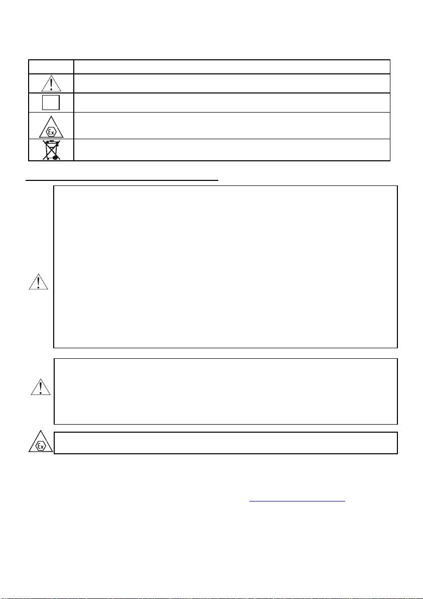
Symbol
Description
Warning to proceed strictly in accordance with the information contained in the
documentation in order to ensure the safety and full functionality of the device.
i
Information particularly useful during installation and operation of the device.
Information particularly useful during installation and operation of a type Ex device.
Information on disposal of used equipment
Symbols used
BASIC REQUIREMENTS AND SAFE USE
- The manufacturer will not be liable for damage resulting from incorrect installation,
failure to maintain the device in a suitable technical condition, or use of the device
other than for its intended purpose.
- Installation should be carried out by qualified staff having the required authorizations to
install electrical and pressure-measuring devices. The installer is responsible for
performing the installation in accordance with these instructions and with the
electromagnetic compatibility and safety regulations and standards applicable to the type
of installation.
- The device should be configured appropriately for the purpose for which it is to be used.
Incorrect configuration may cause erroneous functioning, leading to damage to the device
or an accident.
- In systems with pressure transmitters there exists, in case of leakage, a danger to staff on
the side where the medium is under pressure. All safety and protection requirements
must be observed during installation, operation and inspections.
- If a device is not functioning correctly, disconnect it and send it for repair to the
manufacturer or to a firm authorized by the manufacturer.
In order to minimize the risk of malfunction and associated risks to staff, the device is not
to be installed or used in particularly unfavourable conditions, where the following
dangers occur:
- possibility of mechanical impacts, excessive shocks and vibration;
- excessive temperature fluctuation,
- condensation of water vapour, large dust, icing.
Installation of intrinsic safety versions should be performed with particular care, in
accordance with the regulations and standards applicable to that type of installation.
Changes to the products manufacturing documentation may forestall a paper user updating.
Current Instruction Manual is available at Producer http on www.delta-controls.com.
Page 3

1 IOM-DPT-A: FEB 2014
CONTENTS
I. APPENDIX Exd ............................................................................................................................. 2
II. APPENDIX Exi. ............................................................................................................................. 7
1. INTRODUCTION ......................................................................................................................... 11
2. USER MATERIALS ..................................................................................................................... 11
3. APPLICATIONS AND MAIN FEATURES ................................................................................... 11
4. IDENTIFYING MARKS. ORDERING PROCEDURE .................................................................... 11
5. TECHNICAL DATA ..................................................................................................................... 12
5.1. ELECTRICAL PARAMETERS .................................................................................................................12
5.2. METROLOGICAL PARAMETERS. ...........................................................................................................13
5.3. MEASUREMENT RANGES. ...................................................................................................................13
5.4. OPERATING CONDITIONS. ..................................................................................................................14
5.5. CONSTRUCTION MATERIALS ...............................................................................................................15
6. CONSTRUCTION. ....................................................................................................................... 15
6.1. MEASUREMENT PRINCIPLES. .............................................................................................................15
6.2. CONSTRUCTION ...............................................................................................................................15
6.2.1. Transmitter casing ...................................................................................................................................... 16
6.2.2. Electronic board with display .................................................................................................................... 16
6.2.3. Shields of the measuring insert ................................................................................................................ 16
7. INSTALLATION OF TRANSMITTERS ........................................................................................ 16
8. ELECTRICAL CONNECTION ..................................................................................................... 16
8.1. GENERAL RECOMMENDATIONS ...........................................................................................................16
8.2. ELECTRICAL CONNECTIONS ...............................................................................................................16
8.4. EARTHING .......................................................................................................................................17
9. SETTING AND REGULATION ................................................................................................ .... 17
9.1. MEASUREMENT RANGES, DEFINITIONS ................................................................................................17
9.1.1. Nominal range ............................................................................................................................................. 17
9.1.2. Set range ...................................................................................................................................................... 17
9.1.3. Factory range............................................................................................................................................... 17
9.2. CONFIGURATION AND CALIBRATION ....................................................................................................18
9.3. CALIBRATION. ..................................................................................................................................24
10. INSPECTIONS AND SPARE PARTS .......................................................................................... 24
10.1. PERIODIC INSPECTIONS ...................................................................................................................24
10.2. UNSCHEDULED INSPECTIONS ...........................................................................................................24
10.3. SPARE PARTS. ...............................................................................................................................24
11. PACKING, STORAGE AND TRANSPORT. ................................................................................. 24
12. GUARANTEE .............................................................................................................................. 24
13. ADDITIONAL INFORMATION ..................................................................................................... 24
14. FIGURES. .................................................................................................................................... 25
Fig.1. DPT... transmitters – block diagram. ............................................................................................................ 25
ELECTRICAL CONNECTIONS FOR DPT... TRANSMITTERS ..............................................................................25
Fig.2a. The link of transmitter and communicator or modem to current line by the switch box ( in case of the
resistance in current loop is higher than 250Ω). ................................................................................................... 25
Fig.2b. The link of transmitter and communicator or modem to <SIGNAL+> <SIGNAL-> transmitter terminals in
case of the resistance in current loop is higher than 250Ω. ................................................................................. 26
Fig.2c. The link of transmitter and communicator or modem to <SIGNAL+> <TEST+> transmitter terminals in
case of the resistance in current loop is smaller than 250Ω. ................................................................................ 26
Fig.2d. The link of transmitter and communicator or modem to <SIGNAL+> <SIGNAL-> transmitter terminals in
case of the resistance in current loop is smaller than 250Ω. ................................................................................ 27
Fig.3. DPT-2000ALW smart temperature transmitter ............................................................................................. 28
Fig.4. DPT... display rotation possibility, configuration buttons. ............................................................................ 29
Fig.5. Back lighting jumper view at transmitter electric board (unit display back side) ......................................... 29
Fig.6. The types of shields of measuring insert. ..................................................................................................... 30
Fig.7. The explosion - proof joints of DPT-2000ALW transmitter. .......................................................................... 31
Fig.8. How to lead the casing of DPT-2000ALW transmitter.................................................................................. 32
Page 4

2 IOM-DPT-A: FEB 2014
1180
1453
i
i
I. APPENDIX Exd
DPT–2000ALW TEMPERATURE TRANSMITTER
1. Introduction
1.1. This “Appendix Exd.01” applies to transmitters of type DPT-2000ALW in Exd versions only,
marked on the rating plate as shown in 3 and denoted Exd in the Product Certificate.
1.2. The appendix contains supplementary information relating to the Exd (flame-proof) versions of mentioned
transmitters.
During installation and use of Exd transmitters, reference should be made to DTR.DPT.ALW.03
in conjunction with “Appendix Exd.01”.
2. Use of DPT–2000ALW transmitters in danger zones
2.1. The transmitters are produced in accordance with the requirements of the following standards:
EN 60079-0:2012, EN 60079-1:2007, EN 60079-11:2012, EN 60079-26:2007, EN 60079-31:2009.
2.2. The transmitters may operate in areas where there is a risk of explosion, in accordance with the rating of
the explosion protection design:
I M2 Ex d ia I Mb (steel enclosure only)
II 1/2G Ex ia/d IIC T* Ga/Gb
II 1/2D Ex ia/t IIIC T* Da/Db
-40°C <= Ta <= +45°C/+75°C
KDB 13 ATEX
T* - temperature class for transmitter (for gases) or a maximum surface temperature (for dust) derived in
clause 5.3 and 5.4.
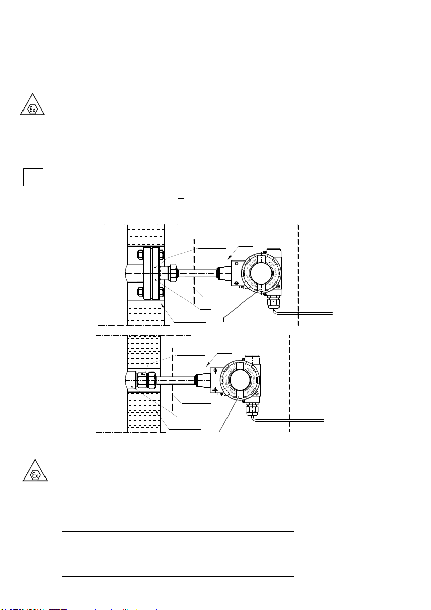
2.3 Transmitter category and hazard areas.
The category 1/2G, contained within the rating, means that the transmitter may be installed within a type 1 or 2
hazard zone. The process connections may connect to a 0 zone type (see the diagram below for an example).
3. Identifying marks.
Flame-proof transmitters must have a rating plate containing the information specified in paragraph 4.1 of
DTR.DPT.ALW.03 and also at least the following:
- CE mark and number of notified unit: mark,
- Designation of explosion protection design, certificate number,
- Power supply,
- Process connection,
- Year of manufacture,
- Temperature use range,
4. User information.
Together with the ordered transmitters, the user will receive:
a) Product Certificate
b) Declaration of conformity
c) Copy of certificate – on request
d) User’s Manual numbered: DTR.DPT.ALW.03 with Appendix Exd0.1.
User can find them b), c), d) at www.delta-controls.com
5. Power supply and exploitation of transmitters
5.1. The transmitter connecting should be made after introduction with present instruction content.
Electrically transmitter should be connected according to scheme at p.6 Appendix Exd.01. Transmitter
electrical installation should be realised with engineering standard requirements.Electrical connections
of transmitters in danger zone should be made by people who have indispensable knowledge and
experience in this branch.
5.2. Earth clamps must be used with earth transmitters. In the event that transmitters come in contact with
structural metal parts or pipes which are connected to the equipotential bonding system, transmitters do
not require to be earthed. Transmitters should be supplied from DC electrical source with voltage
max.45V from transformer feeders or other devices which have at least a strengthened isolation among
Exd VERSION
Page 5
3 IOM-DPT-A: FEB 2014
Temperature transmitter
Tp
Thermal shield
Safe area
Safe area
Zone 0
Zone 0
Temperature transmitter
measuring insert
Shield of the
Zone 1 or 2
Tap
Thermal shield
Tp
Zone 1 or 2
Shield of the
measuring insert
Tap
Thermal isolation
Thermal isolation
Tp[C]
Temperature class and ambient temperature Ta[C]
Tp75C
T6 and Ta=45C
T5 and Ta=75C
Tp>75C
T4 and T5 Ta=70C
T3 and T2 Ta=65C
T1 Ta=60C
i
primary and secondary windings in which don’t appear voltage higher than 250V. The duty of power
supply installation with above mentioned requirements rests on user.
Appendix Exd.01
5.3. Measurements of operating temperature of transmitter
5.3.1. After installing the DPT-2000ALW transmitter for the medium maximum expected temperature and
expected the maximum ambient temperature measure out Tp temperature of the most hot place on the
surface of transmitter and determine the temperature transmitter class or a maximum surface
temperature according to p. 5.4.
When measuring the warmed media, above ambient, is recommended to determine the temperature of the
stub while is screwed into the transmitter or at the wall of the pipe or tank as shown below.
5.3.2. When medium is heated above ambient temperature it is allowed to determine the temperature class
of the transmitter or the maximum surface temperature Tp through the adoption of a maximum
temperature of the medium which provides the technological process. Measurement of Tp isn’t then
necessary.
If during the measurement of Tp for maximum temperature expected for the medium is not possible to
ensure the maximum expected ambient temperature after the measurement of Tp
one can estimate the potential growth in temperature Tp due to the increase of ambient temperature.
5.3.3. If the other elements of the plant have or may have a temperature higher than the highest temperature Tp
on the transmitter, security conditions must be ensured in accordance with accepted principles in such cases
5.4. Determination of the transmitter temperature class T * for gas and the maximum surface temperature
1. Determine the temperature class of the transmitter for the gas or the maximum temperature for
combustible dust depending on the temperature Tp from the formula:
T*Tp+0,1Tp+5K for class T3..T6
T*Tp+0,1Tp+10K for class T1, T2
2. Determine the maximum surface temperature transmitter for combustible dust from the formula:
T*Tp+0,1Tp
3. The following table contains the values of permissible ambient temperature depending on the
temperature Tp and temperature class of the transmitter.
Tp- transmitter temperature measured in clause 5.3
Page 6
4 IOM-DPT-A: FEB 2014
Ex power supply
see p.5..
_
+
TEST
short-circuit( jumper)
Fuse: In = 0,05A, Un = 250V
according to EN 60127
RD
Communicator
Safe area
_
TEST
SIGNAL
_
+
.
32
VWX
MNO
DEF
YZ#
5 6
PQR*+/
9
GHI
8 0
@%&
1
4
JKL
7
STU
ABC
REF2PV F4
F3 F4PFF1
+
Ro
Hazardous area
i
i
i
In the case of significant increase in medium temperature measurement of Tp must be executed again and
again must be specified the temperature class for the gas or the maximum surface temperature
combustible dust.
5.5. With regard on kind of casing material (light alloy with large aluminium content), the user is obliged to
assure, that possibility of hitting casing does not step out in place of transmitter installation.
5.6. In transmitter casing are two holes to assembly of cable intakes from thread M20x1,5 or 1/2 NPT.
5.7. Normally transmitters are delivered without installed glands but with blank plugs (corks) in the second
hole. They are at table 1 and table 2 at list of packing glands and plugs agreeable with production
documentation and accepted by certificate station. Customer should install packing glands according to
tables 1 and plugs according to tables 2 (if plugs aren’t installed) or other accordance with flame-proof
standards.
5.8. It is necessary apply a shield cable or without shield cable with round cross-section in protection from
elastomer, not moisture absorbing, for example: YKSLY 2 * 1, YnTKSYekw 1 * 2 * 1, LIYCY 2 * In case
of need of use cable about different building customer should co-ordinate this with transmitters
manufacturer to choose intakes with cable diameter.
5.9. The general principles of connecting and the exploitation of transmitter in Exd realization should be
compatible with principles and relating standards for Exd casing devices how in p.2.1, in this including
also : EN600079-14, EN60079-17.
5.10. During service must be made a check of the tight fastening of covers and the packing glands and the
fastening of the cable in the glands. The casing and supply line must be inspected for mechanical
damage, and the transmitter rating plate for legibility. Periodic checks should also be made of the
diaphragm, which should not carry signs of damage. During maintenance it is recommended that the
threads of the covers be lubricated with non-acid vaseline.
Because of the transmitter damage possibility, the ambient temperature should not be allowed to
become higher than 80C, even when there is no explosion risk.
6. How to connect Exd transmitter DPT-2000ALW
Page 7

5 IOM-DPT-A: FEB 2014
Type of packing glands
Producer
Screw
Feature
Other marking
No of certificate
Note
501/423
HAWKE
M20x1,5
Exd IIC
dimension OS, O, A
Baseefa 06 ATEX 0056X
501/421
HAWKE
M20x1,5
Exd IIC
dimension OS, O, A
Baseefa 06 ATEX 0056X
ICG 623
HAWKE
M20x1,5
Exd IIC
dimension OS, O, A
Baseefa 06 ATEX 0058X
501/453
HAWKE
M20x1,5
Exd IIC
dimension OS, O, A
Baseefa 06 ATEX 0056X
*
501/453/RAC
HAWKE
M20x1,5
Exd IIC
dimension OS, O, A
Baseefa 06 ATEX 0056X
*
501/453/Universal
HAWKE
M20x1,5
Exd IIC
dimension OS, O, A
Baseefa 06 ATEX 0057X
*
ICG 653
HAWKE
M20x1,5
Exd IIC
dimension OS, O, A
Baseefa 06 ATEX 0058X
* 8163/2-A2F
STAHL
M20x1.5
EXd IIC
SIRA06ATEX1188X
A2F, A2FRC, SS2K
CMPProducts
M20x1,5
Exd IIC
SIRA06ATEX1097X
E1FW, E1FX/Z,
E2FW, E2FX/Z
CMPProducts
M20x1,5
Exd IIC
SIRA06ATEX1097X
*
T3CDS, T3CDSPB
CMPProducts
M20x1,5
Exd IIC
SIRA06ATEX1283X
*
PX2K, PXSS2K,
PX2KX, PXB2KX
CMPProducts
M20x1,5
Exd IIC
SIRA06ATEX1097X
*
Type of plug
Producer
Screw
Feature
Other marking
No of certificate
Note
AGRO AG
M20x1,5
Exd IIC
Nr kat.
475
HAWKE
M20x1,5
Exd IIC
477
HAWKE
M20x1,5
Exd IIC
i i
i
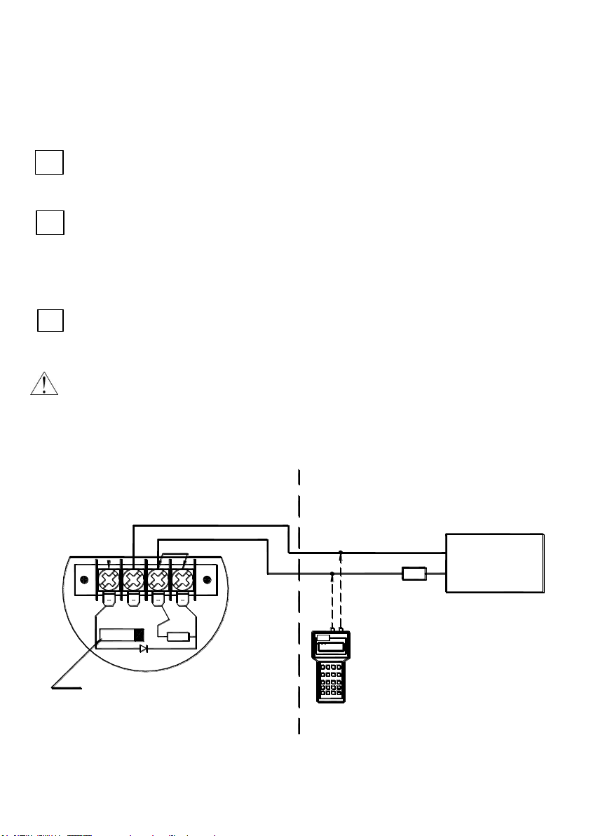
Appendix Exd.01
In danger zone don’t unscrew transmitter covers and don’t change the display position or
its back lighting.
In case of transmitter calibration outside danger zone is possible communicator connecting to
<SIGNAL+> and <TEST+> terminals. Transmitter is furnished in communication resistor (RD = 240Ω),
closed with jumper at <SIGNAL-> and <TEST-> terminals installed by manufacturer. RD resistor can be
use then, when it is necessary to communicate with transmitter from its terminals and the load
resistance (Ro) in current loop is lover then 250Ω. Than <SIGNAL-> and <TEST-> terminals have to
be open.
Permissible gap of joint is smaller than this was defined in norm EN 60079-1:2008 and can not be
greater than passed value on fig. 7.
Blocking cover method before unscrewing and plumbing possibility is shoved at fig 8.
It is not permitted to repair or otherwise interfere with the transmitter’s electrical circuits
in any way. Damage estimation and repair possibility may be assessed by the
manufacturer or another authorized party only.
Table 1 Permitted packing glands.
Table 2. permitted plugs
*) for special cable only.
Page 8

6 IOM-DPT-A: FEB 2014
i
i
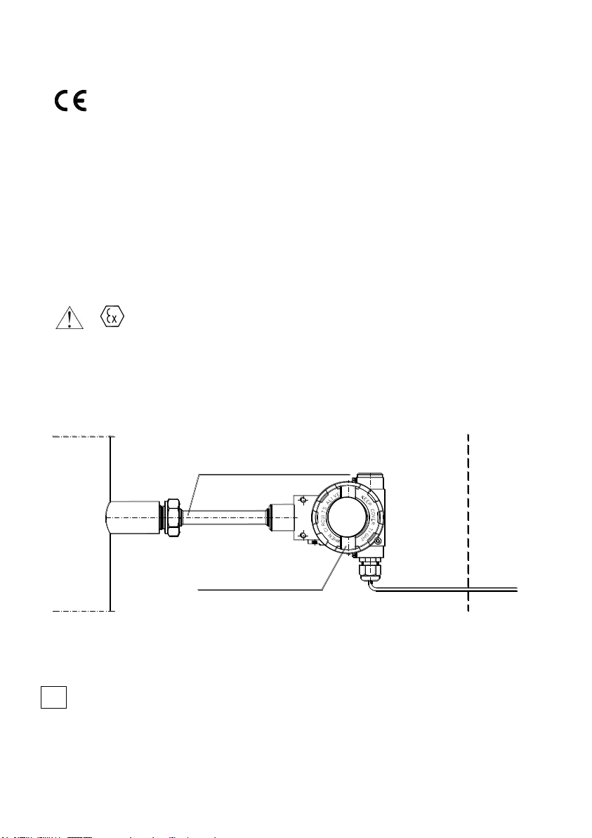
Specific conditions of use:
Permissible gap of flameproof joint marked L4 is less than defined in norm EN 60079-1:2007 and
cannot be greater than passed value on fig. 7.
Temperature class (T* for gases) or maximum surface temperature (T* for dust ) depends mainly on
the temperature of the process (temperature of the controlled medium), and the method of
installation on site. Therefore, to determine the temperature Tp hottest places on the surface of the
transducer housing (practically cover the sensor) in contact with explosive atmosphere in conditions
of installation on site and proceed in accordance with p.5.3 Appendix Exd.01.
Page 9
7 IOM-DPT-A: FEB 2014
1180
1453
Shield of the measuring insert
Temperature transmitter
Zone 0 Zone 1 or 2 Safe area
i
Appendix Exi
II. APPENDIX Exi.
DPT–2000ALW TEMPERATURE TRANSMITTER
1. Introduction
1.1. This “Appendix Exi” applies to transmitters of type DPT-2000ALW in Ex versions only, marked on
the rating plate as shown in 2 and 3 and denoted Ex in the Product Certificate.
1.2. The appendix contains supplementary information relating to the Ex versions of these transmitters.
During installation and use of Ex transmitters, reference should be made to DTR.DPT.ALW.02(ENG) in
conjunction with “Appendix Exi”.
2. Use of DPT–2000ALW transmitters in danger zones.
2.1. The transmitters are produced in accordance with the requirements of the following standards:
EN 60079-0:2012, EN 60079-11:2012, EN 60079-26:2007, EN 50303:2000
2.2. The transmitters may operate in areas where there is a risk of explosion, in accordance with the rating of
the explosion protection design:
COMING SOON!
(the temperature class of transmitter depends from medium temperature)
2.3. Transmitter category and hazard areas
The category 1/2G, contained within the rating, means that the transmitter may be installed within a type
1 or 2 hazard zone. Shield of the measuring insert DPT-2000ALW, may connect to a 0 zone type (see the
diagram below for an example).
Exi VERSION
3. Identifying marks..
Intrinsically safe transmitters must have a rating plate containing the information specified in paragraph 4.1 of.
DTR.DPT.ALW.03 and also at least the following:
CE mark and number of notified unit
designation of explosion protection design, certificate number
values of parameters such as. Ui, Ii, Ci, Li,
year of manufacture
Page 10
8 IOM-DPT-A: FEB 2014
Rw
Uo
I DIi
Io
Io
Ui
Uo
Q
I
Rw
U
Q
Ii
transmitter
U
Q
2
U
Q
I
0
U0(UQ –U0)
Rw
transmitter
4P
0
I
0
Appendix Exi
4. User information.
Together with the ordered transmitters, the user will receive:
a) Product Certificate,
b) Declaration of conformity
c) Copy of certificate – on request
d) „User’s Manual numbered: „DTR.DPT.ALW.03” with Appendix Exi..
User can find them at www.delta-controls.com
5. Permitted input parameters (based on data from the FTZÚ 14 ATEX
certificate, and certification documentation).
The transmitters should be powered via the associated power feeding and measurement devices
provided with the relevant intrinsic-safe certificates. The parameters of their outputs to the danger zone
should not exceed the limit power supply parameters for the below specified transmitters.
Temperature classes T4, T5, or T6 depend on the input power and maximum ambient temperature – see p.
5.1, 5.2, 5.3.The ambient temperature range is reduced to Ta = -20ºC to +60ºC if the devices is installed as
group I M1 equipment.
External connections are made via integral terminals and cable glands which must be of certified type if they
are mounted on the version f or combustible dust hazard application.
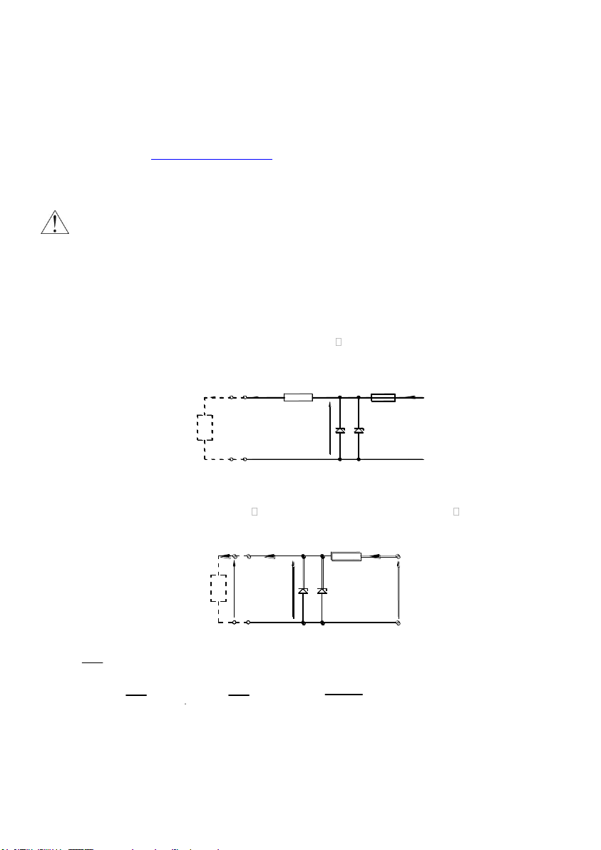
5.1. - for power supply with a “linear“ characteristic
Ui = 30V Ii = 0,1A Pi = 0,75W Ta ≤ 80ºC and T4, Ta 70C and T5, Pi = 0,45W Ta ≤ 40ºC and T6
Power supply with a “linear” characteristic may be e.g. a typical barrier with parameters
Uo = 28V Io = 0.093A Rw = 300.
Fig.1. Power supply from a source with “linear” characteristic
5.2. – for power supply with a “trapezial” characteristic
Ui = 24V Ii = 50mA Pi = 0,6W Ta 80°C and T5 and Pi = 0,45W Ta 40°C and T6
Example of power supply from a source with “trapezial” characteristic (see Fig. 2).
Fig. 2. Power supply from a source with “trapezial” characteristic
If Uo < then parameters Uq, Io, Po are interrelated as follows:
UQ = , Rw = , P0 = for U0 ≤ 1/2U
5.3. - for power supply with “rectangular” characteristic
Ui = 24V Ii = 25mA Pi = 0,6W Ta 80C and T5
The supply of power from a source with a “rectangular” characteristic means that the voltage of the Ex power
supply remains constant until current limitation activates.
The protection level of power supplies with a “rectangular” characteristic is normally “ib”.
The transmitter powered from such a supply is also a Ex device with protection level “ib”.
Example of practical provision of power supply.
– use a stabilized power supply with Uo=24V with protection level „ib” and current limited to Io=25mA.
Q
Page 11
9 IOM-DPT-A: FEB 2014
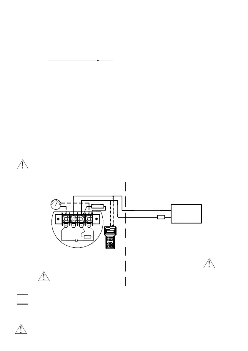
In hazardous areas, connections
to the control terminals must be
made using only instruments which
are permitted to be used in such areas.
mA
Ex-Milliammeter
TEST
To measure the current in the transmitter without
disconnecting the signalling circuit, connect
a milliammeter to control sockets <TEST+>, <TEST->.
Hazardous area Safe area
Aplisens KAP-03Ex Communicator
_
_
+
TEST
SIGNAL
+
RD
.
32
VWX
MNO
DEF
YZ#
5 6
PQR*+/
9
GHI
8 0
@%&
1
4
JKL
7
STU
ABC
REF2PV F4
F3 F4PFF1
Jumper
a Ex power supply
see p.5.
+
Ro
_
28V – 13.5V** – (300Ω* * 0,02A)
0,023A
Uzas. – 13.5V**
0,023A
i
Delta Controls KAP-03Ex Communicator
Appendix Exi
5.4. Input inductance and capacity: Ci = 20nF, Li = 1,1mH
5.5. Supply voltage min.: 13.5VDC **
5.6. Load resistance:
from 28V linear supply
Ro max [Ω] = for transmitter without display back lighting
from a source with “trapezial” or “rectangular” characteristic supply
Ro max [Ω] =
*) barrier resistance
**) 16,5V for transmitter with display back lighting
5.7. Temperature
Temperature of transmitter’s surface from regard temperature of shield part as on figure in point 2.3. can't
surpass the admissible values of temperatures for temperature class of steam and gases according with
standard PN-EN 60079-0.
Simultaneously the casing temperature should not surpass max. temperature value Ta definite for
conditions power supply in Certificate Exi and p.5 of Appendix Exi.
6. How to connect Ex transmitters DPT-2000ALW.
The transmitter and other devices in the measuring loop should be connected in accordance
with the intrinsic-safety and explosion-safety regulations and the conditions for use in
dangerous areas.
Failure to observe the intrinsic-safety regulations can cause explosion and the resulting hazard
to people.
The transmitter is equipped in additional communication resistor RD = 240 Ω.
During normal operation terminals <Signal –> and <Test –> are shorted.
RD resistor is used when you wish to communicate with the transmitter locally (from its terminals) and
Ro < 250. Terminals <Signal –> and <Test –> must be opened.
Transmitter electrical installation should be realised with engineering standard requirements.
It is not allowed to repair or otherwise interfere with the transmitter’s electrical circuits in any
way. Damage and possible repair may be assessed only by the manufacturer or another
authorized party.
Page 12

10 IOM-DPT-A: FEB 2014
i
i
Specific conditions of use
Allowed operating temperature range specified in point 5 Appendix Exi
Operating temperature range is restricted in the range of Ta = -20°C to 60°C if the device is
operating in a Group I M1.
Page 13

11 IOM-DPT-A: FEB 2014
i
INTRODUCTION
1.1. This Manual is intended for users of DPT-2000ALW smart temperature transmitters in normal and
intrinsic-safety versions, containing the data and guidelines necessary to understand the functioning of the
transmitters and how to operate them. It includes essential recommendations concerning installation and use,
as well as emergency procedures.
Parameters and information given in the remaining part of the manual regard simultaneously all the
transmitters, their intrinsically safe versions and version with various types of casings.
1.2. Additional data on DPT-2000ALW transmitters in Ex versions is contained in the appendix
designed to DTR.DPT.ALW.03 Appendix Exi. During installation and use of the transmitters in Exi
version reference should be made to DTR.DPT.ALW.03 in conjunction with Appendix Exi.
1.3. Additional data on DPT-2000ALW transmitters in Exd versions is contained in the appendix
designed to DTR.ADPT.ALW.03 Appendix Exd.01. During installation and use of the transmitters in
Exd version reference should be made to DTR.DPT.ALW.03 in conjunction with Appendix Exd.01
2. USER MATERIALS
Transmitters are delivered in single and/or multiple packs.
Together with the transmitter are delivered:
a. Product certificate, which is also as the warranty card
b. Declaration of conformity - on request,
c. Copy of ATEX certificate – on request
d. User’s Manual numbered „DTR.DPT.ALW.03”.
Items b), c), d) are available at: www.delta-controls.com
3. APPLICATIONS AND MAIN FEATURES
3.1. The DPT-2000ALW smart temperature transmitters are designed to measure temperature in various
branches of industry in normal conditions as well as in conditions of danger the explosion of gas and dust.
3.2. The DPT-2000ALW transmitters may be equipped with various types of measuring insert casings
which allows for their application in various conditions.
3.3. The DPT-2000ALW transmitters characterized by:
a. Two-wire power supply (4…20mA current loop),
b. Digital signal processing (filtration, linearization, compensation),
c. Possibility of local configuration from display panel or remotely (HART protocol).
d. Autodiagnostic system
e. Ambient temperature effect compensation
f. Input/output galvanic separation.
4. IDENTIFYING MARKS. ORDERING PROCEDURE
4.1. Identifying marks
Every transmitter carries a rating plate containing at least the following information:
a. manufacturer name
b. CE mark
c. transmitter type: DPT-2000ALW
d. basic range
e. set range
f. power supply voltage
g. output signal
h. year of manufacture and serial number
Page 14

12 IOM-DPT-A: FEB 2014
i
Usup[V]-12V *
0,023A
Special version: Exi, Exd, IP-67, another
kołnierza
Set (calibrated) range
Type of shield
Mounting length
Connection thread: M20x1,5, G1/2”, M27x2, G1” or flange type
Nominal range
Alarm signal
DPT-2000ALW/___/___/L=.…mm/___/___÷___°C/___÷___C/___
4.1.1. The DPT-2000ALW transmitters in intrinsically safe version have additional designations, which
are specified in DTR.DPT.ALW.03 Appendix Exi.
4.1.2. The DPT-2000ALW transmitters in Exd version have additional designations, which are specified
in DTR.DPT.ALW.03 Appendix Exd.01.
4.2. Ordering procedure
Procedure of ordering
Example: Temperature transmitter DPT-2000ALW, shield T1, version Exi, mounting length 250 mm,
connection flange DN50 PN40, nominal range: -40 do 550 °C, calibrated range: 0 do 300 °C,
alarm signal for example 23 mA.
DPT-2000ALW / T1 / Exi / L=250 mm / DN50 Pn40 / - 40 ÷ 550 °C / 0 ÷ 300 °C / 23 mA.
5. TECHNICAL DATA
5.1. Electrical parameters
Power supply for normal version 12 * ÷ 55V DC
Power supply for intrinsic-safe versions - in
accordance with „Appendix Exi”
Power supply for Exd versions - in accordance with
„Appendix Exd.01”
Output signal 4÷20mA + Hart Rev.5.1
Communication realised via a 4÷20mA signal and Hart transmission
using KAP-03 communicator or SH05 Delta Controls
modem or PC computer with DPT2000 software
.
Resistance for communication (Hart) 250÷1100, min 240Ω
Load resistance Ro[] =
Load resistance for intrinsic-safe versions – in accordance with „Appendix Exi”
)
*
15 V for transmitters with display backlight.
Page 15

13 IOM-DPT-A: FEB 2014
0 250 500 750 1000
10
15
20
25
30
35
40
45
Ro[ ]
Vmin [V]
Umin = f(Ro) z podświetleniem
0 250 500 750 1000
10
15
20
25
30
35
40
45
Ro[ ]
Vmin [V]
Umin = f(Ro) bez podświetlenia
50
55
50
55
1250
1500 1750
1250
1500 1750
Alarm Type
Value of Alarm Current
Alarm Type
Value of Alarm Current
NORMAL LOW
3,75 mA
CUSTOM (value of alarm
current is defined by user)
Value of alarm current in
interval
3,6 mA 23 mA
NORMAL HIGH
21,6 mA
NAMUR LOW
3,6 mA
LAST VALUE
(transmitter does not
update analog exit)
Alarm current value is equal
to the current value in the
time preceding the event
which giving an alarm.
NAMUR HIGH
21,0 mA
Sensor type
Min. measuring range
Nominal range
Calibrated range
Pt 100
10 °C
- 200 ... 550 °C
0 ... 100 °C
Ni-Cr-Ni /K/ *
10 °C
- 40 ... 550 °C
0 ... 300 °C
i
Ro[Ω]
Ro[Ω]
Vmin [V]
Vmin [V]
Umin = f(Ro) without display backlight
Umin = f(Ro) with display backlight
The value of transmitter minimal supply voltage can be calculated from the following formula:
Umin = 12 + 0,023 x Ro [V] for transmitter operating without LCD display backlight
(or read from the drawing below)
Umin = 15 + 0,023 x Ro [V] for converter operating with LCD display backlight.
(or read from the drawing below)
Transmitters made in Ex version are delivered with display backlight switched off. The user can switch
the backlight on by himself.
Supply voltage dependence on current loop resistance
Safe working area (grid) upper colour area.
Voltage for insulation testing 500 VAC or 750 VDC, see p.8.3.
Excess voltage protection see p.8.3.
List of current alarms
5.2. Metrological parameters.
Additional voltage damping 0...30s
Total error of transmitter (digital value) ± (0,05 + 0,05%·z + 0,001·|t|) °C for sensor Pt100
± (0,5 + 0,05%·z)°C for sensor K and t 375°C
± (0,5 + 0,05%·z + 0,002·(t-375))°C for sensor K and t
>375°C
Additional analogue output error ± 0,04%·z
where:
|t| - modulus of measured temperature in °C
t - the value of measured temperature in °C
z - the range width of transmitter in °C
5.3. Measurement ranges.
* Recommended for measurements with strong vibrations.
Page 16

14 IOM-DPT-A: FEB 2014
5.4. Operating conditions.
Ambient temperature range -40°C 85°C
Operating temperature for intrinsic-safe versions (Exi) in
accordance with „Appendix Exi”.
Operating temperature for Exd versions in accordance
with „Appendix Exd.01”.
Relative humidity up to 98%
Medium temperature range Pt100 - 200 ... 550 °C
N-Cr-NiAl - 40 ... 550 °C
Thermal compensation range -25 … 75 0C
5.4.1. Electromagnetic Compatibility (EMC), immunity
Rating according to EN 61326-1,2for industrial applications
Electrostatic Discharge Immunity (ESD):
EN 61000-4-2; S3 level: contact ±6kV, air ±8kV; criterion A
Conducted Radio Frequency:
EN 61000-4-6; 0,15… 80MHz, 10V; criterion A
Radiated electromagnetic Field:
EN 61000-4-3; 80… 2 000MHz – 10V/m, 2 000 … 2 700MHz – 1V/m; criterion A
Electrical Fast Transient (Burst Immunity)
EN 61000-4-4; ± 2kV power supply port/earth, ± 1kV signal port/earth; criterion A
Electrical Slow Transient (Surge Immunity):
EN 61000-4-5; ±0.5kV (±1kV) 0,5kV differentia mode, 1kV common mode; criterion B
5.4.2. Electromagnetic Compatibility, emission:
According to CISPR16-1, CISPR 16-2, class B, distance to the antenna 3m, quasi-peak measuring:
Radiated emission: 0,15 … 30MHz, 80-52dBμV/m;
Conducted emission: 0,01 … 0,150MHz, 96-50dBμV/m;
30 … 2000MHz, <54dBμV/m
0,150 … 0,350MHz, 60-50dBμV/m;
0,35 … 30MHz, <50dBμV/m
5.4.3. Climatic immunity: dry heat, cold, humidity, salt mist:
Dry heat:
EN 60068-2-2, test B; T = 700C, RH = max 55%
Cold :
EN 60068-2-1, test A; T = -250C,
Damp heat cycle:
EN 60068-2-30, test D ; (T = 550C, RH = min95%, 24h)x2
5.4.4. Mechanical immunity
Shocks:
EN 60068-2-27, 50g/11ms
Vibrations:
EN 60068-2-6, test Fc; up to 1,6mm for 2 … 25Hz, up to 4g for 25 … 100Hz
Page 17

15 IOM-DPT-A: FEB 2014
Type of shield
Shield
Material of shield
Connection type
F [mm]
L [mm]
I [mm]
SW1
18h7
100
140, 200
35
65
15HM,
10H2M,
316Lss
-
SW2
24h7
140, 200
65
15HM,
10H2M,
316Lss
-
GB1, GN1
9 x 1
100, 160,
250, 400
-
316Lss
M20x1,5,
G1/2
G1
11 x 2
100, 160,
250, 400
-
316Lss
M27x2,
G1
T1
11 x 2
100, 160,
250, 400
-
316Lss
Flange PN, DIN, ANSI
5.4.5. Insulation Resistance
>100 MΩ @110V transmitters with gas arresters
>100 MΩ @750V DC transmitters without gas arresters (Exi)
5.4.6. High Voltage Test
500V AC, or 750V DC, 1min, transmitters without gas arresters (Ex applications)
75V AC, or 110V DC, 1min, transmitters with gas arresters
5.4.7. Enclosure ingress protection
EN 60529, IP 66,67
5.5. Construction materials
Electronics casing High pressure cast of aluminium alloy, lacquered with chemical-resistant oxide
Shields - materials, diameters and lengths.
enamel, colour yellow (RAL 1003), or stainless steel ss316L – not varnished.
6. CONSTRUCTION.
6.1. Measurement Principles.
A signal from measuring sensor, i.e. from thermometer resistor Pt100 or thermocouple, corresponding to
measured medium temperature, is delivered to the input of analogue-digital converter and converted to digital
form. In digital form it is sent, through an optoelectronic galvanic barrier, to the microcontroller. The
microcontroller reads measured values and, using built-in algorithms, calculates an exact value of temperature
on the basis of these algorithms. Calculated value is shown on integrated LCD display, which can be configured
depending on the needs (see p. 9.2.5). Digital value of measured temperature is converted to analogue signal
4...20[mA]. Built-in modem BELL202 and implemented communication stack HART Rev.5.1 allow for the
communication with the converter, using PC computer and appropriate software or communicator.
The transmitter’s output is fitted with a radio-noise filter and other elements protecting against ESD.
A block diagram of the transmitter is presented in Figure 1.
DPT ... converters monitors the operation of their measuring systems and the correctness of calculations and in
case when discrepancies occur they inform about an error displaying a message on LCD display and
generating an alarm current in the current loop (depending on configuration).
The measuring signal of sensor has a galvanic separation from measuring line. Thanks of that construction the
measurement susceptibility at interferences is reduced as well as the enlarged safety of work in the Ex and
flameproof applications.
6.2. Construction
The basic units of transmitter are: casing, shield with process connection, measuring sensor and electronic
units, transforming signal from measuring sensor into unified output signal.
Page 18

16 IOM-DPT-A: FEB 2014
i
i
6.2.1. Transmitter casing
A casing of DPT... transmitter is made of high-pressure casting of aluminium alloy or 316L steel. It consists of a
body, two bolted side covers (full and with pane), cable inlets and plug with M20x1,5 or ½ NPT thread.
Inside the casings is divided into two chambers, separated by a header. An additional header, with a ribbon
cable is intended for transmitting a signal from temperature sensor to the inside of a transmitter.
The casing is equipped with internal and external earth terminals.
6.2.2. Electronic board with display
The electronic board, along with a display, is installed in a housing made of polycarbonate, in the bigger of two
casing’s chambers, where it is possible to rotate it by 180every 90. A connecting board with terminal strip
(fig. 2a) and the elements of interference filter and protecting elements are installed in the second chamber.
6.2.3. Shields of the measuring insert
Within the framework of basic version there is a possibility to select one of five types of casings shown on fig.6.
The SW1 and SW2 shields are high-tension shields designed to welding.
The GB1, GN1 and G1 shields have threaded process connection and designed to screw in assembly sockets.
The T1 shield have flange process connection.
7. INSTALLATION OF TRANSMITTERS
The DPT–2000ALW transmitters can operate in any position.
During the installation of temperature transmitters the casing of electronic system should be protected against
exceeding of allowed temperatures. Suitable thermal covers should be used or the transmitters should be
mounted in such a position so the heat from medium does not heat up the casing.
When the transmitters are mounted, particularly in areas endangered by explosion, also the
heat conduction of sensor metal casing and ambient temperature for ensuring proper work
conditions and temperature classes should be taken into consideration.
Data specified in ”Annex Exi” are applicable for intrinsically safe versions.
Data specified in ”Annex Exd01” are applicable flameproof versions.
8. ELECTRICAL CONNECTION
8.1. General recommendations
8.1.1. It is recommended that twisted pair cabling be used for the signal lines. If the transmitter and signal line
are subject to a large amount of electromagnetic interference, then shield pair cable should be used. The signal
wires should not run alongside network power supply cables or near to large electrically-powered devices.
The devices used together with the transmitters should be resistant to electromagnetic interference from the
transmission line in accordance with compatibility requirements. It is also beneficial to use anti-interference
filters on the primary side of the transformers, the power supplies used for the transmitters and apparatus used
in conjunction with them.
8.1.2. Wet or rising damp inside transmitter can cause its damage.
When the isolation of the wires in the packing gland is ineffective (for example, when single
wires are used) the opening of the gland should be carefully sealed with an elastic sealing
compound to obtain IP66 protection. It is useful to form the segment of the signal wire leading
to the packing gland into a protective loop to prevent condensation from running down in the
direction of the gland..
8.2. Electrical connections
The DPT-... transmitters are to be connected as shown in fig. 2a – 2d.
In DPT-... transmitters, a 240Ω resistor is permanently fitted in series in the transmitter’s current circuit
and blocked up with jumper between <SIGNAL –> and <TEST –> as shown in fig.2a and 2b.
When the resistance in the current loop is lower than 240Ω it is necessary to jumper disassemble to
Hart communication.
Page 19

17 IOM-DPT-A: FEB 2014
1
2
3
Type of
transmitter
Protection between wires (TVS
diodes) – permitted voltage
Protection between wires and earth and/or casing – type
of protection, permitted voltage
DPT...
(normal version)
68V DC
Plasma surge arresters - 230V DC
DPT...
(Exd version)
68V DC
Not applicable
DPT...
(Exi version)
39VDC
Not applicable
i
8.3. Protection from excess voltage
8.3.1. The transmitters may be in danger from excess voltage caused by connection faults or atmospheric
electrical discharge.
Protection from excess voltage between the wires of the transmission line is provided by TVS diodes installed
in all types of transmitter (see the table, column 2).
8.3.2. In order to protect against excess voltage between the transmission line and the casing or earth (not
prevented by the diodes connected between the transmission wires), additional protection is provided in the
form of plasma surge arresters (see the table, column 3).
Also external protective devices may be used, e.g. the UZ-2 Delta Controls system, or others. When the
transmission lines are long, it is advantageous to use one protective device near the transmitter (or inside it), and
another near entry points to other devices used in conjunction with it.
Internal protection of transmitters:
8.3.3. The voltage in the protective elements must not exceed the maximum permitted values given in columns
2 and 3 of the table.
The insulation test voltages (500V AC or 750V DC) given in 5.1.1 refer to transmitters plasma surge
arresters - such protection is not used in Exi versions of transmitters.
8.4. Earthing
The transmitters are fitted with internal and external earth terminals.
9. SETTING AND REGULATION
9.1. Measurement ranges, Definitions
9.1.1. Nominal range
The maximum range of temperature, which the transmitter can measure is called the “nominal range” (for
specifications of nominal ranges see section 5.3).
The width of the nominal range is the difference between the upper and lower limits of the nominal range.
The internal characteristic conversion curve for the nominal range is coded in the transmitter’s memory.
This is the reference curve used when making any adjustments which affect the transmitter’s output signal.
9.1.2. Set range
When the transmitter is in use the term “set (calibrated) range” is used. The set range is the range whose
lower end-point corresponds to an output current of 4mA and whose upper end-point corresponds to a current
of 20mA (or 20mA and 4mA respectively when the conversion curve is inverted).
The set range may cover the whole of the nominal range or only a part of it.
The width of the set range is the difference between its upper and lower end-points. T
he transmitter may be set to any range within the nominal range of temperature values, subject to the
restrictions set out in the table in section 5.3.
9.1.3. Factory range.
in case when lacks information about measuring range, transmitters are setting on " factory range".
/0 ... 100/ °C – factory range for transmitter with Pt100 sensor.
/0 ... 300/ °C – factory range for transmitter with "K" thermoelement.
Page 20

18 IOM-DPT-A: FEB 2014
9.2. Configuration and Calibration
9.2.1. The transmitter has features which enable metrological and identification parameters to be set and
altered. The configurable metrological parameters affecting the transmitter’s output current include the
following:
a. lower end-point of the set range
b. upper end-point of the set range
c. unit
d. time constant
e. type of characteristic curve: linear or radical
f. decimal index
9.2.2. Other identification parameters, not affecting the output signal, include: device address, device type
code, factory identification code, factory device code, number of preambles (3÷20), UCS, TSD, program
version, electronics version, flags, serial number, label tag, description tag, date tag, message, record number,
sensing module number.
The process of setting the parameters listed in 9.2.1 and 9.2.2 is called “Configuration”.
9.2.3. Remote configuration of transmitters
Configuration and Calibration of the transmitter are carried out using an Delta Controls KAP communicator,
DPT2000 configuration software or using library EDDL software (software PC with Hart/RS232 converter).
A description of the functions of the KAP communicator is contained in the KAP Communicator Operating
Manual, and information on the Hart/RS232 converter can be found on the Hart/RS232/01 Converter
information sheet.
For purposes of remote calibration a system shown on the scheme on fig. 2a 2d should be prepared.
9.2.4. Local configuration of transmitters
If the option of local configuration is active, operator can change transmitter set using buttons being below
display. The access to buttons will get after unscrewing the side cover. Then we can also change the display
position turning it with 900 angle position. (see fig. 4).
If the option of local configuration is active, operator can change transmitter set using buttons being below
display. To enter at the local set change of the work mode, you should press one button and hold its about 4s.
If using buttons can't change the transmitter configuration , the local transmitter configuration is switched of
and to its switching on is necessary to use the KAP 3 Calibrator.
The buttons are signed with symbols: [↑] [↓] [◙]
After pressing by 4 seconds any of buttons there will appear on display “EXIT”.
If we will confirm this announcement across pressing and holding button [[◙] by 1 sec, we will go out from the
local change of the MENU set. If we will not confirm, we can move in MENU and change interesting us
parameters. The time of pressing [↑]] [↓] [◙] has to be longer than 1s.
Longer pressing and holding of [↑] [↓]buttons will cause an automatic scrolling through MENU structure, with step
of 0.33 s
Pressing button [↑] moves up in tree's structure MENU
Pressing button [↓] moves down in tree's structure MENU
Pressing [◙]confirms choice and leads change.
If no actions are taken in the area of MENU for a period longer than 2 min., then MENU mode will be quitted
and a process variable will be displayed.
Page 21

19 IOM-DPT-A: FEB 2014
|
EXIT (First announcement which will see after inclusion of Menu Local.
| If you will confirm this option, you will go out from Local Menu
| and you will come back to continue of measuring)
|
SET LRV_________ (The Setting of the range of the set LRV beginning)
| \
| BACK (Return to Local Menu. If you will confirm this option,
| | you will come back to main tree of Local Menu)
| |
| XXX•XX (Will display current value LRV)
| \
| (After confirmation will entry in mode of edition)
| ↓
| +/- (Choose and confirm sign introduced parameter)
| ↓
| 0000 (Introduce in sequence , digit after digit, 5 digital number with point
| or without point. After confirmation the last 5 digit of the parameter
| transmitter will confirm the party of command by the "DONE"
| announcement or the proper number of error will notify.
| The parameter will be written down in units "UNIT")
|
SET URV_________ (The setting of the end of the set URV range)
| \
| BACK (Return to Local Menu. If you will confirm this option,
| | you will come back to main tree of Local Menu)
| |
| XXX•XX (Will display current value URV)
| \
| (After confirmation will entry in mode of edition)
| ↓
| +/- (Choose and confirm sign introduced parameter)
| ↓
| 0000 (Introduce in sequence, digit after digit, 5 digital number with point
| or without point. After confirmation the last 5 digit of the parameter
| transmitter will confirm the party of command by the "DONE"
| announcement or the proper number of error will notify.
| The parameter will be written down in units "UNIT")
|
UNIT____________ (Setting of the temperature unit)
| \
| BACK (Return to Local Menu. If you will confirm this option,
| | you will come back to main tree of Local Menu)
| |
| | (Confirm one of the following units across
| | longer press button ◙. After parameter confirmation
| | transmitter will confirm the party of command by the "DONE")
| °C
| K
| °F
| °Rk
|
Page 22

20 IOM-DPT-A: FEB 2014
DAMPING________ (Setting of the solid temporary suppression of the process variable)
| \
| BACK (Return to Local Menu. If you will confirm this option,
| | you will come back to main tree of Local Menu)
| |
| | (Confirm one of the following values time constant across
| | longer press button ◙. After parameter confirmation
| | transmitter will confirm the party of command by the "DONE")
| 0 [S]
| 2 [S]
| 5 [S]
| 10 [S]
| 30 [S]
|
TRANSFEr_______ (Setting of the current output form)
| \
| BACK (Return to Local Menu. If you will confirm this option,
| | you will come back to main tree of Local Menu)
| |
| | (Confirm one of the following characteristics across
| | longer press button ◙. After parameter confirmation
| | transmitter will confirm the party of command by the "DONE")
| LINEAR (Linear)
| SQRT (Square root)
| SQRTX^3 (Square root with X^3)
| SQRTX^5 (Square root with X^5)
| SPECIAL (User’s)
| SQUARE (Square)
|
LCD1VARiable____ (Type of the process variable displayed on LCD1)
| \
| BACK (Return to Local Menu. If you will confirm this option,
| | you will come back to main tree of Local Menu)
| |
| | (Confirm one of the following option across
| | longer press button ◙. After parameter confirmation
| | transmitter will confirm the party of command by the "DONE")
| |
| CURRENT (On LCD1 will displayed current value in current loop)
| |
| PERCENT (The percent value output signal will displayed on LCD1)
|
Page 23

21 IOM-DPT-A: FEB 2014
LCD2VARiable____ (Type of the process variable displayed on LCD2)
| \
| BACK (Return to Local Menu. If you will confirm this option,
| | you will come back to main tree of Local Menu)
| |
| | (Confirm one of the following option across
| | longer press button ◙. After parameter confirmation
| | transmitter will confirm the party of command by the "DONE")
| |
| TEMPERATURE (The process variable will displayed on LCD2)
| |
| USER (The user’s units will displayed on LCD2)
| |
| UNIT (The current unit or user’s unit alternately
| | with process variable will displayed on LCD2)
| |
| NO UNIT (The current unit or user’s unit alternately
| with process variable will not displayed on LCD2)
|
LCD2 DP_________ (The process variable point position on LCD2)
| \
| BACK (Return to Local Menu. If you will confirm this option,
| | you will come back to main tree of Local Menu)
| |
| | (Confirm one of the following option across
| | longer press button ◙. After parameter confirmation
| | transmitter will confirm the party of command by the "DONE")
| |
| XXXXX•
|
| XXXX•X
|
| XXX•XX
|
| XX•XXX
|
| •XXXXX
|
FACTORY________ (Come back to factory setting)
| \
| BACK (Return to Local Menu. If you will confirm this option,
| | you will come back to main tree of Local Menu)
| |
| | (Confirm the command as bellow across longer press
| | button ◙. After parameter confirmation transmitter will
| | confirm the party of command by the "DONE")
| |
| RECALL
|
RESET__________ (The program enforcement of the transmitter restart)
| \
| \
| BACK (Return to Local Menu. If you will confirm this option,
| | you will come back to main tree of Local Menu
| |
| | (Confirm the command as bellow across longer press
| | button ◙. After parameter confirmation transmitter will restart.
|
RESET
Page 24

22 IOM-DPT-A: FEB 2014
MID_WP_________ (Lock modify the parameters associated with MID)
| \
| BACK (Back to the Local Menu. If you approve this option,
| | return back to the main menu Tree Local)
| |
| | (Submit one of the following through constant
| | ◙ pressing. Once approved, the parameter transmitter
| | will confirm receipt of the command message "DONE")
| |
| |
| ON (Lock Activation parameters affecting the metrology)
| |
| OFF (Turns lock parameters affecting the metrology)
Local Menu, error reports..
During executing in Local Menu some functions, LCD2 announcement can be displayed on the screen.
The error displaying evidences about no realization of command of Local Menu.
The shortened description of errors announcements is showed below.
ERR_L07 [in_write_protected_mode]. Error will ensue out when we try to change setting in Local
ERR_L09 [applied_process_too_low]. Error will ensue out when given parameter (temperature)
will too low. Zeroing or the range setting verifying is necessary.
ERR_L10 [applied_process_too_low]. Error will ensue out when given parameter (temperature)
will too low. Zeroing or the range setting verifying is necessary.
ERR_L14 [span_too_small]. Error will ensue out when in result of setting range executing change
the width of the range will be smaller than admissible.
ERR_L16 [acces_restricted]. Error will ensue out when the service of Local Menu is switched off,
Menu, but transmitter is protected before recording. To to make the change of setting with
Local Menu using, transmitter has to have the included service of Local Menu as well as
switched off protection before record. These parameters modification is possible by using
KAP -03 communicator, DPT2000 program or software using library EDDL.
default setting:
Local Menu service switched on
protection before record switched off
and the user tries to call out the Menu Local service. You should switch on the service of
Local Menu with the KAP-03 communicator, DPT2000 program, or software using library
EDDL.
Page 25

23 IOM-DPT-A: FEB 2014
9.2.5.1. Setting up a local LCD display
The LCD display configuration can do in dependence from needs. Changes of the display options in local
MENU are possible using buttons or remote way using communicator, or the PC software. If it is necessary the
display switching off is also possible. The display switching of function is possible with using communicator or
PC software only.
There 3 main displays are visible:
LCD1 – the current or guidance percent preset range display. In accordance with display configuration the
current value in 4 -20 mA current loop, or percent guidance preset range is possible to display.
LCD2 – the measured temperature digital value display; the calibrated temperature value according to
user’s units display; the process variable units or user’s units display; the MENU announcement and other
information or warning announcement display. In the case the digital temperature value or the calibrated
temperature value display, the sign „–„ can be visible before displayed value. The decimal point position is
possible to set in local MENU or remotely. The temperature unit or user’s unit can be displayed. The
transmitter makes possible rescale on the user's individual the temperature value. To make this is
necessary with using communicator or PC software write the corresponding to beginning and to end
values of setting range as well as write the own unit name. After activating user's mode the rescale value
will be visible on display.
LCD3 – information display. During normal operation is designed for continuous display of the base unit or
the user units. In case of errors in the transmitter's work , it displays an error number. In manual mode, the
local change settings menu displays options of selecting the setting. It also displays errors related to the
implementation of commands in the local menu of the settings change.
Display backlighting - Local display is equipped in backlight, switching on and switching off with
jumper on electronic board. How to handle display backlight is shown in Figure 5. Figure 4 shows
how to change the display position by rotation.
After configuration it is important to protect the transducers using command HART [247].
During work transmitter should be safe prior to entries. This prevents accidental or intentional
changes configurational data. The protection function is accessible in KAP03 communicator, “
DPT2000 Configurator” software, as well as, in applying DD or DMT programs libraries.
Page 26

24 IOM-DPT-A: FEB 2014
i i
9.3. Calibration.
The transmitter can be calibrated with reference values of the standard operating temperature sensor
transmitter to its scale (calibration input) or to current output 4 ... 20 (20 ... 4) mA - (current calibration).
The values set calibration points need not be equal to the upper and lower limit of the basic range. But they can
not exceed out up and down. The width of the calibration range shall not be less than the minimum width of the
setting range. In order to achieve the best accuracy it is recommended that the calibration points were close to
the beginning and end of the setting range. Calibration can be made using the KAP-03 or KAP-03Ex
communicator according to the procedure described in the "User's Guide" IO.KAP-03 p 11.3. or other tools
provided in clause 9.2.3.
10. INSPECTIONS AND SPARE PARTS
10.1. Periodic inspections
Periodic inspections should be made in accordance with the regulations to which the user is subject.
During inspection, the shield of the measuring insert should be checked for loose connections and leaks, the
electrical connectors should be checked with regard to tightness and the state of the gaskets, packing glands.
Check the characteristic conversion curve by following the procedures for “Calibration” and, where appropriate,
“Configuration”.
10.2. Unscheduled inspections
If the transmitters are installed in a location where they may be exposed to mechanical damage,
hydraulic impulses or excess voltage, or transmitter operate abnormal – inspections should be carried
out as required, check the characteristic of processing.
Where it is found that the signal in the transmission line is absent or its value is incorrect, a check
should be made on the line and its terminal connections.
Check whether the values of the supply voltage and load resistance are correct.
If a communicator is connected to the power supply line of the transmitter, a fault in the line may be
indicated by the message “No response” or “Check connection”.
If the line is in order, check the operation of the transmitter.
10.3. Spare parts.
Parts of the transmitter which may be subject to wear or damage and require replacement: cover and packing
gland gaskets .
Other listed parts, due to the specific features and requirements of explosion-protected
devices, may be replaced only by the manufacturer or by a firm authorized by the manufacturer.
11. PACKING, STORAGE AND TRANSPORT.
The transmitters should be packed singly or in sets, in such a way as to protect them from damage during
transportation.
The transmitters should be stored in multiple packs under cover, in a place free of vapours and reactive
substances, with an air temperature between +5°C and +40°C, and relative humidity of not more than 85%.
During transportation, the transmitters should be packed and secured so as to prevent them from shifting.
Any means of transport may be used, provided direct atmospheric effects are eliminated.
12. GUARANTEE
The manufacturer guarantees the proper operation of the transmitters for a period of 24 months from the date
of purchase and servicing provided under the guarantee and following the guarantee period. In the case of
special versions, the guarantee period shall be agreed by the manufacturer and the user, but shall not be less
than 12 months.
13. ADDITIONAL INFORMATION
The manufacturer reserves the right to make constructional and technological changes which do not lower the
quality of the transmitters.
Page 27

25 IOM-DPT-A: FEB 2014
Input
circuitmodule
Sensing
1
+
_
system
Power supply/
measurement
min.250
Load resistance
Output
Processor
a/c
Converter
circuit
Modem
Communicator
filter
Noise
2
D
Memory
-
+
SIGNAL
240
Power
Ro
mA
4÷20 mA
+
_
F1
.
32
VWX
MNO
DEF
YZ#
5 6
PQR*+/
9
GHI
8 0
@%&
1
STU
4
JKL
ABC
7
RE PV F4PF
F2 F3 F4
APT2000
Configurator
BELL
202
RS 232
Communicator
Current loop
Switch box
+TEST
-TEST
JUMPER
supply
D-SOFT
14. FIGURES.
Fig.1. DPT... transmitters – block diagram.
For successful communication with transmitter the resistance in measuring loop, behind connected
device to communication, should be higher than 250Ω. If necessary install the additional resistor in the
line. The communicator or modem connecting ways to the measuring loop are presented at diagrams.
During increasing of resistance in the measure loop at making the good transmission, is necessary to
make sure that the tension falls at sum resistances in the loop don't lower minimum tension at
transmitter terminals. (see p.5.1.).
Electrical connections for DPT... transmitters
Fig.2a. The link of transmitter and communicator or modem to current line by the switch box ( in case of the
resistance in current loop is higher than 250Ω).
Page 28

26 IOM-DPT-A: FEB 2014
+TEST
-TEST
-
+
SIGNAL
240
Ro
mA
4÷20 mA
+
_
F1
.
32
VWX
MNO
DEF
YZ#
5 6
PQR*+/
9
GHI
8 0
@%&
1
STU
4
JKL
ABC
7
RE PV F4PF
F2 F3 F4
BELL
202
RS 232
Communicator
Current loop
JUMPER
APT2000
Configurator
Power
supply
+TEST
-TEST
-
+
SIGNAL
240
4÷20 mA
+
_
F1
.
32
VWX
MNO
DEF
YZ#
5 6
PQR*+/
9
GHI
8 0
@%&
1
STU
4
JKL
ABC
7
RE PV F4PF
F2 F3 F4
BELL
202
RS 232
Communicator
Current loop
Ro
mA
JUMPER
APT2000
Configurator
Power
supply
To measure the transmitter current without
disconnecting the measuring loop, connect
a milliammeter to control terminals <Test ->
and <Test +>.
DPT2000
Configurator
D-SOFT
D-SOFT
Fig.2b. The link of transmitter and communicator or modem to <SIGNAL+> <SIGNAL-> transmitter terminals in
case of the resistance in current loop is higher than 250Ω.
Fig.2c. The link of transmitter and communicator or modem to <SIGNAL+> <TEST+> transmitter terminals in
case of the resistance in current loop is smaller than 250Ω.
Page 29

27 IOM-DPT-A: FEB 2014
+TEST
-TEST
-
+
SIGNAL
240
4÷20 mA
+
_
F1
.
32
VWX
MNO
DEF
YZ#
5 6
PQR*+/
9
GHI
8 0
@%&
1
STU
4
JKL
ABC
7
RE PV F4PF
F2 F3 F4
BELL
202
RS 232
Communicator
Current loop
JUMPER
Ro
mA
APT2000
Configurator
Power
supply
DPT2000
Configurator
D-SOFT
Fig.2d. The link of transmitter and communicator or modem to <SIGNAL+> <SIGNAL-> transmitter terminals in
case of the resistance in current loop is smaller than 250Ω.
If Ro in current loop is lower than 250Ω is necessary to connect 240Ω resistor to current loop by
remove jumper from <SIGNAL-> and <TEST-> terminals.
After communication jumper should cam back at its place.
Page 30

28 IOM-DPT-A: FEB 2014
101,5
rotation
Lock preventing
Earthing terminal
The electronic
circuits
FIELD TERMINALS
The electrical
terminals side
18
and display side
132 18
133
M20x1,5 lub 1/2 NPT
cable
-
+
-TEST
+TEST
SIGNAL
240
Packing gland
165
L
L
of the casing
Fitting socket
M20x1,5 or G1/2"
M20x1,5
or G1/2"
M20x1,5
or G1/2"
O6
L
150
Fig.3. DPT-2000ALW smart temperature transmitter
Page 31

29 IOM-DPT-A: FEB 2014
przewody
Jumper in radial position
(as at photo) –back lighting off;
jumper in circular
position –back lighting on.
Move the electronic unit from transmitter casing, take up
the upper part of the casing with display from the catch
and revolve its to left or to right to the display setting at
needed position.
Rotation possibility ±1800 with 90° pitch.
Screw on the display unit screws and display cover
unscrew the
display cover
and casing
display screws
±180o with 90
0
pitch
Configuration
buttons
wires
Fig.4. DPT... display rotation possibility, configuration buttons.
Fig.5. Back lighting jumper view at transmitter electric board (unit display back side)
Page 32

30 IOM-DPT-A: FEB 2014
Excision for key 24mm
Thermowell
Fig.6. The types of shields of measuring insert.
Page 33

31 IOM-DPT-A: FEB 2014
MINIMUM WIDTH OF JOINT AND MAXIMUM GAP FOR GROUP IIC ENCLOSURES
1/2NPT
12,7
L7
L8
10
1/2NPT
O15
M20x1,5
M72x1,5
13,3
12
L4
L6
L5
9
Nr
O15
+0,027
-0,040
-0,070
M20x1,5
M72x1,5
engaged(6)
width of joint min.10
min.6 threads
cemented joints
1
2
engaged
width of joint min.12,5
min.5 threads
min.5 threads
0,097
2
2
2
engaged(8)
A
B
A
L7
L6
B
L4
L8
L5
A-A
L4
Scale:2:1
B-B
(min. real)
width of joint
L [mm]
diameter
quantity
of joint
PN-EN 60079-1:2008
according to
minimum
D [mm] d [mm]
D-d [mm]
Fig.7. The explosion - proof joints of DPT-2000ALW transmitter.
Page 34

32 IOM-DPT-A: FEB 2014
CIRCUIT IS ALIVE
WARNING-
FIELD TERMINALS
O
C
R
V
E
V
E
T
S
R
C
I
U
I
A
L
K
P
E
E
W
H
C
N
E
T
I
H
G
T
I
Lock the cover tight by unbolting the screw
Fig.8. How to lead the casing of DPT-2000ALW transmitter.
Page 35

33 IOM-DPT-A: FEB 2014
Page 36

Page 37

4 DTR.APC.APR
 Loading...