

Page 1

CS64A
Color Sensors
010627a
(Address updated)
Page 2

Contents
1. Specifications ............................................................................... 4
2. Introduction ................................................................................. 5
3. Mounting the CS64A................................................................... 7
4. Wiring the CS64A ..................................................................... 10
5. Adjustment................................................................................. 11
6. Sample Quick Test..................................................................... 12
7. Threshold Setting ...................................................................... 13
8. Characteristics ........................................................................... 13
1.1 Ordering Information................................................................. 4
2.1 Primary Features........................................................................ 6
3.1 Moving Line Applications......................................................... 8
3.2 Fixed Applications..................................................................... 8
8.1 Temperature............................................................................. 13
8.2 Edge Effects............................................................................. 14
8.3 Angle of CS64A to Material.................................................... 14
8.4 Distance Performance.............................................................. 14
8.5 General Information ................................................................ 14
9. Recalibration.............................................................................. 15
10. Maintenance............................................................................... 15
11. Frequently Asked Questions..................................................... 16
12. Troubleshooting......................................................................... 20
13. Support....................................................................................... 20
14. Repairs........................................................................................ 20
15. Warranty.................................................................................... 21
Although great effort has been taken to ensure the accuracy of the information in
this document, Delta Computer Systems, Inc. cannot accept responsibility for
problems resulting from errors or omissions in this document. The information
in this document is subject to change without notice.
Neither Delta Computer Systems, Inc. nor anyone else involved in the creation,
production, delivery, or support of this product shall be liable for any direct,
indirect, or consequential injuries or damages arising out of the use, the results of
use, or inability to use this product.
Copyright (c) 1996, 1997, 1998, 1999, 2000, 2001 Delta Computer Systems, Inc.
Printed in USA
2
Page 3
3
Page 4
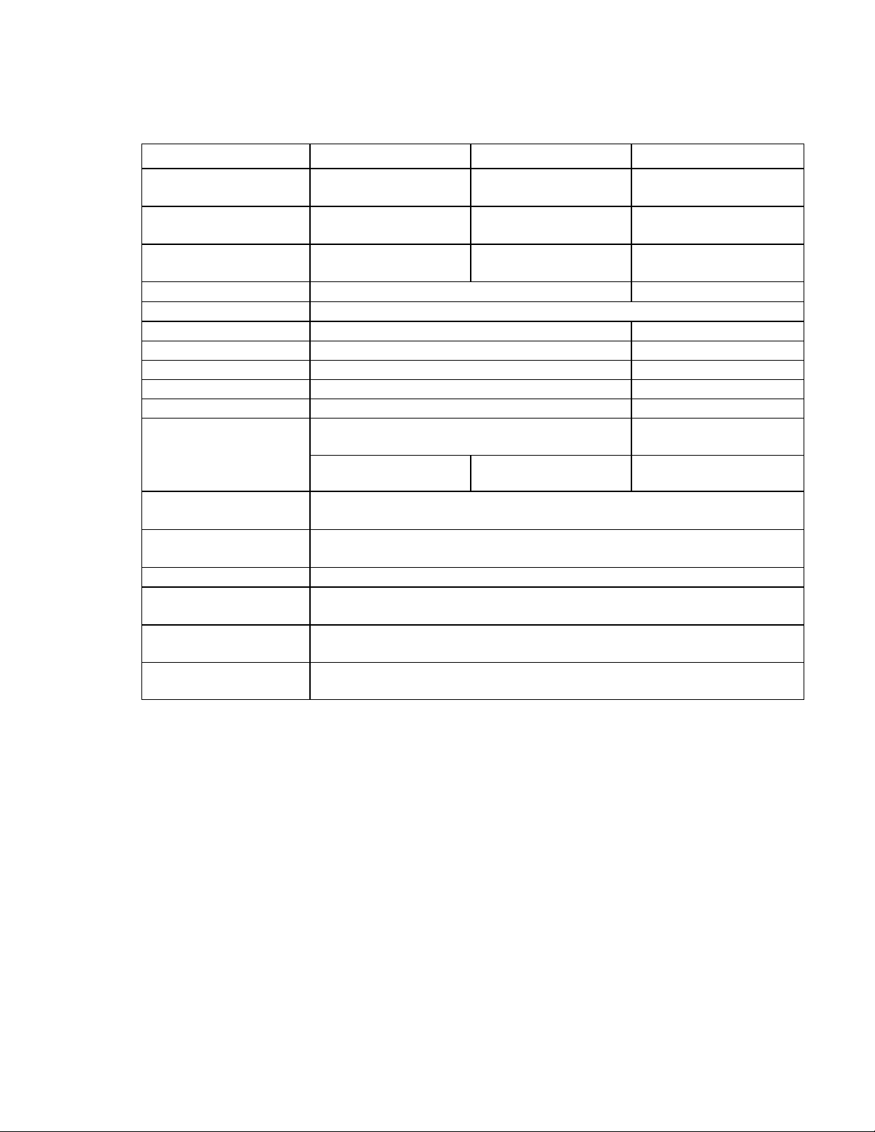
1. Specifications
Model
Sensor-to-Object
Standoff Distance
Sensor-to-Object
Sensing Range
Sensing Area
Response Time
Output Update Rate
Analog Outputs
Color 1
Color 2
Color 3
Color 4
Calibration
At Standoff
Distance
Ratio Variation with
Sensing Distance
Temperature
Stability
Supply Voltage
Current
Consumption
Enclosure
Environment
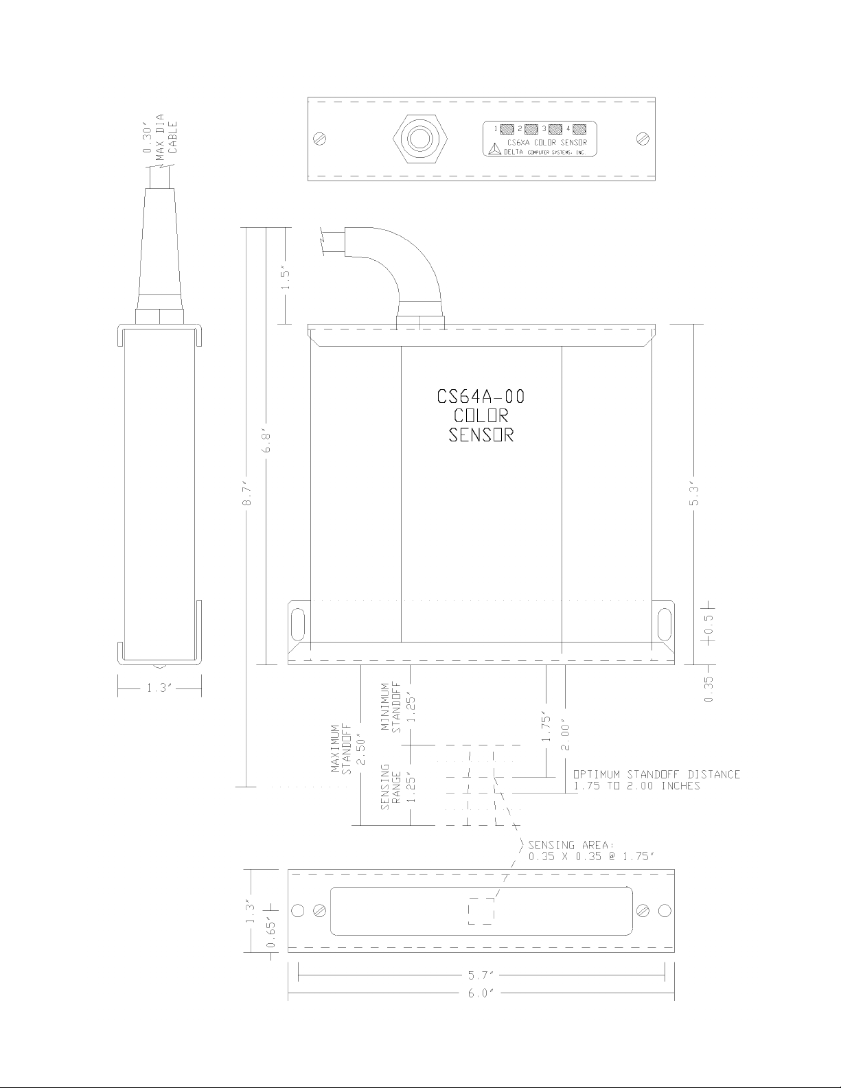
CS64A-00
1.75 to 2.0” (4550mm) optimum
1.25” (32mm): 1.25 to
2.5” sensor-to-object
0.35” (9mm) square @
1.75” (45mm)
CS64A-02
4.75 to 5.0” (120125mm) optimum
1.25” (32mm): 4.25 to
5.0 sensor-to-object
0.7” (18mm) square @
4.75” (120mm)
CS64A-04-BNR
3.75 to 4.0” (95-100mm)
optimum
2.75” (70mm): 3.0 to
5.75 sensor-to-object
0.48” (12mm) square @
3.75” (95mm)
62us to read all 4 colors 47us to read all 3 colors
< 1 millisecond
Four, 0 to 10V at 5mA max Three, 0-10V, 5mA max
470nm Blue 470nm Blue
880nm Near-Infrared 880nm Near-Infrared
660nm Red 660nm Red
570nm Green N/A
9.5V and 100% ratios (Red/NIR, Blue/NIR, and
Green/NIR) with >99% diffuse reflection
9.5V and 100% ratios
(Red/NIR, Blue/NIR)
1.75” (45mm) 4.75” (120mm) 3.75” (95mm)
0.6% max per 0.25” (6mm) change in sensor-to-object distance (<2% max
over sensing range)
Ratios 0.1%/C typical
+24VDC ±5%
100mA maximum
Dust tight; 6.0 x 5.3 x 1.3” (153 x 135 x 33mm) excluding strain relief;1.25
lb (2.75 kg)
+10 to +40C operating; -25 to +85C storage; 0 to 90% humidity, noncondensing
1.1 Ordering Information
CS64A-00 1.75 to 2.0 inch (45 to 50mm) nominal standoff distance
CS64A-02 4.75 to 5.0 inch (120 to 125mm) nominal standoff distance
CS64A-04-BNR 3.00 to 5.75 inch (75 to 145mm) working distance, Blue, NIR, and Red
Other color sensors are available with standoff distances to 6", update rates to 50
microseconds as well as other color combinations and options. Contact Delta or your
local Delta color sensor distributor for more information, or visit our web page at
www.deltacompsys.com.
6/27/2001 DELTA Computer Systems, Inc. (360) 254-8688
4
Page 5

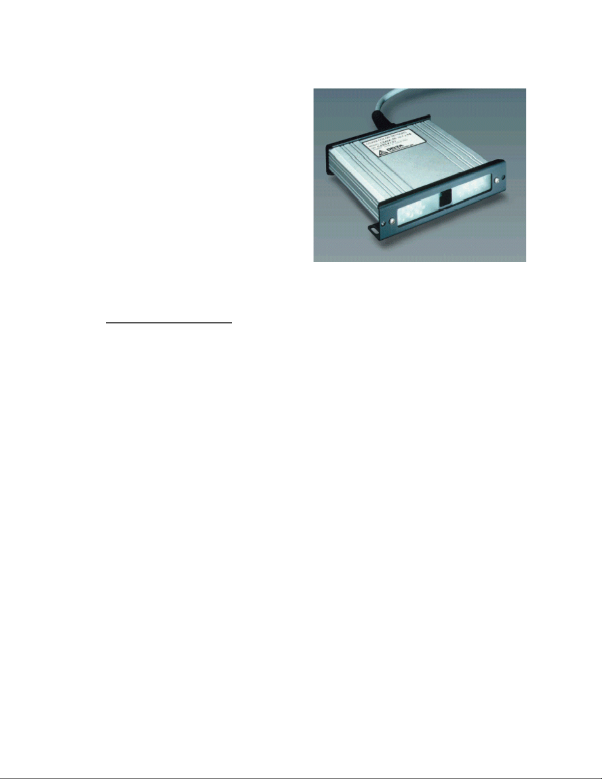
Introduction
The CS64A color sensor contains a light generation system to illuminate the object to be
sensed, and a light receiving system to read the diffuse reflected light from the object.
The light generation system consists of four sets of light emitting diode (LED) light
sources—a total of 28 LEDs. The CS64A determines color by turning on just one set of
LEDs (one color) at a time and analyzing the light captured by it’s precision silicon
photodiode.
The CS64A color sensor reads four different wavelengths--Blue, Near-infrared (NIR),
Red, and Green. Reflected energy in each of the color ranges appears as a 0-10V signal
on the corresponding four analog outputs, making the CS64A compatible with any PLC,
PC, or system having 0-10V analog inputs.
Using the ratios of Red/NIR, Blue/NIR and Green/NIR, it is possible to distinguish
between a wide range of colors. Very similar colors typically have a 10% difference in at
least one ratio, while some colors may have ratio differences 70% or more.
The CS64A was developed specifically for on-line color sensing applications, including:
• Distinguish between objects to ensure the correct color object is being processed on
your automated production line, such as vehicle headliners, door and body panels,
and seats
• Sort objects by color
• Monitor color variations of materials during manufacture such as carpets and ceramic
tile
• Detect presence of metal coatings or wood varnish
• Monitor color quality of granular foods such as sugar
• Detect paint marks where bar coding is impractical
• Detect over- or under-cooked baked goods
The diffuse LED lighting and large sensing area make the CS64A relatively immune to
material grain direction and similar variations. The CS64A-00's long standoff distance of
1.75 to 2" and sensor-to-target distance variation tolerance of 1.25 to 2.5" are important
benefits in many applications as well. The CS64A-02 has an extended standoff distance
of 4.75-5.00” while the CS64A-04-BNR has a very wide working range of 2.75” (3.00 to
5.75” sensor-to-object).
Each of the CS64A’s four 0-10V analog outputs has an adjustment potentiometer and an
indicator LED. The indicator LEDs come on when the output reaches about 2 volts and
the indicator LED intensity increase with amplitude.
The high-intensity LEDs in the CS64A’s lighting system have a typical life of 100,000
hours. (Actual intensity is 64 times higher than it appears since the LEDs are pulsed at a
low duty cycle).
The intensity of all LEDs varies with temperature due to the properties of the
semiconductor materials used. The CS64A sensors use feedback circuitry to maintain
amplitudes over a wide range of temperature and to compensate for light loss due to
normal LED aging. This feedback along with the long life of the LEDs, greatly reduces
the need for recalibration.
5
Page 6
1.2 Primary Features
• Superior color detection on a wide range
of materials
• Versatile analog outputs allow unlimited
sorting and show data trends
• Long sensing range and standoff distance
• Four color ranges are sensed—from blue
to near-infrared
• Near-infrared differentiates between
materials such as leather, vinyl, and cloth
• Robust LED lighting system—no light
bulbs to burn out
• Feedback compensation for LED aging
• Fast, one millisecond update rate
For more information on Delta’s growing lines of color sensors, motion controllers, and
other industrial products, visit our web site at:
www.deltacompsys.com
6
Page 7
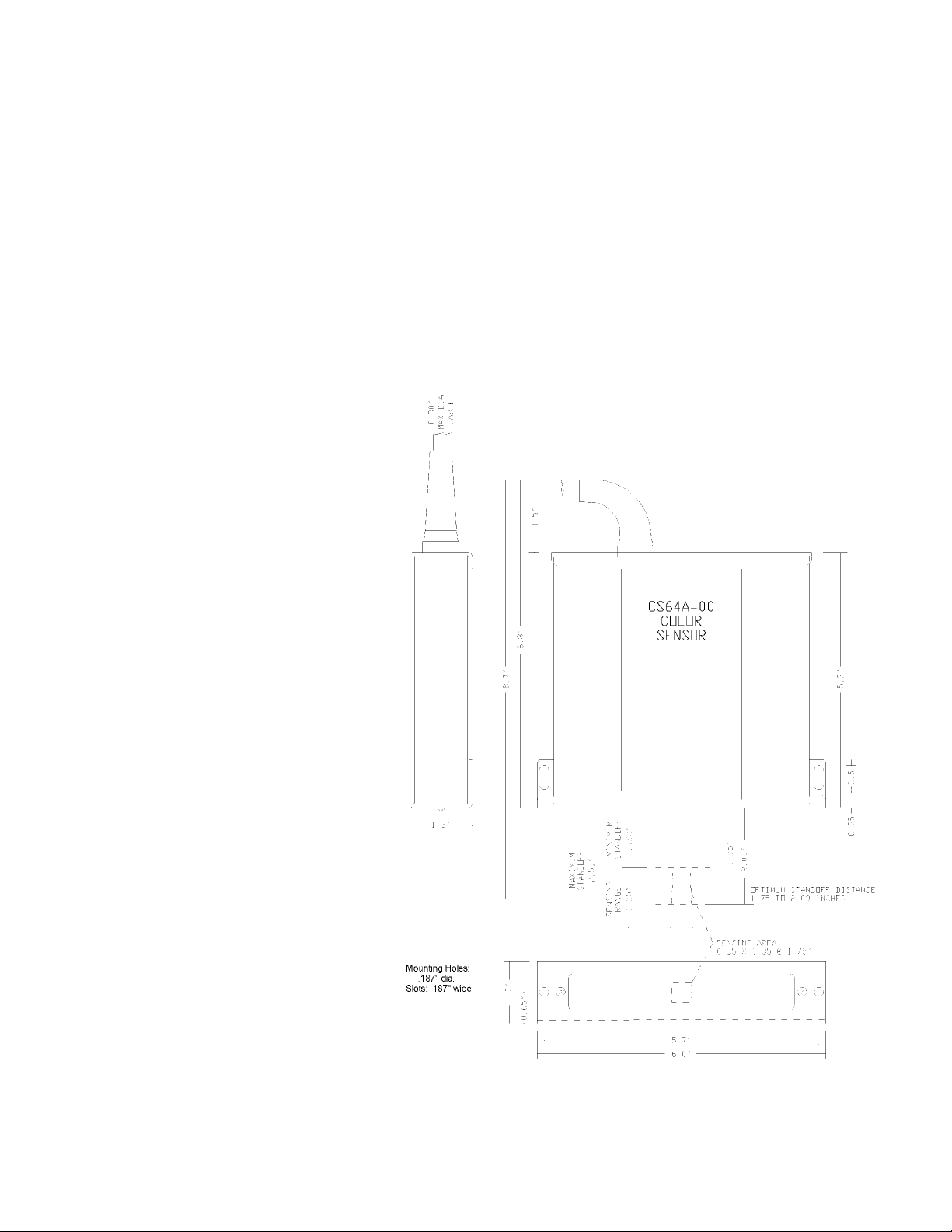
2. Mounting the CS64A
In general, the sensing area should be as dark as possible (especially if small differences
in color are to be detected). Any light that is in the sensing area that is not generated by
the CS64A is a source of error. The Blue and Green colors are more sensitive to
extraneous light than are the Red and NIR colors since these LEDs are less intense.
Small amounts of constant light can sometimes be tolerated, but bright pulsing lights
(such as fluorescent) and sunlight should never be allowed to shine into the sensing area.
Direct sunlight can also cause overheating (or damage if it shines through the lens).
The CS64A-00 should be mounted such that the bottom is 1.75 to 2 inches from the
average target object position. The sensing range will be +-1/2 inch allowing for sensor
to object movement. (See
Specifications for standoff
and range for other models).
The CS64A’s lighting system
is much more intense than it
appears because of the low
duty cycle of its light emitting
diodes (LEDs). However, in
most applications it is
desirable to keep extraneous
light out of the sensing area.
This area includes not only
the area that is directly read
by the sensor (0.35” square
for the CS64A-00), but also
the immediate surrounding
surfaces since light will
reflect into the direct sensing
area. The optimum type of
light block depends on the
application and the
environment.
If it is possible that the
CS64A could be bumped hard
enough to cause damage, it
should be mounted such that
it is protected. To minimize
electrical noise, the CS64A
enclosure should be
grounded.
If the sensor is used in a wet
or corrosive area, order the
OEM package. This package
allows the CS64A to be
mounted inside a NEMA 4X
enclosure. For convenience, a window kit is also available.
7
Page 8

2.1 Moving Line Applications
t
r
q
In cases where the product moves under the sensor as on an assembly line, it is usually
important not to overly restrict headroom (distance from sensor to the target object).
2.1.1 Adequate space and moderate light levels (normal factory lighting, no direct
sunlight)
It is usually adequate to use a plate mounted above the line at a distance approximately
equal to the sensor standoff distance (~2” for the CS64A-00). This plate should be 12”
square or more with the CS64A mounted in the center. The bottom side of the plate
should be painted with a good quality optically flat black paint such as Krylon 1602 Ultra
Flat Black. This plate will prevent extraneous light from being reflected into the sensing
area.
Top View: CS64A with Light Block Plate
CS64A-00
Color Senso
Side View: CS64A with Light Block Plate
Color Sensor Light
Block
Plate
Optional curtain
or brush
2.1.2 Limited space and high or varying light levels
If there is not enough room for a large flat plate, or if a usable size plate is inadequate, a
curtain or brush can be used to block additional light. Ideally, a plate of the largest
practical dimensions would still be used, with the curtains or brushes mounted on the
edges. The bottom edge should just clear the normal travel of the objects. The curtains
and brushes should be of dark materials. If the curtain or brush is close to the direct
sensing area (within 2”), it should be tested to make sure that it does not reflect in the
visible or near-infrared regions (see manual for information on how to test with the
CS64A).
Objects travel
underneath
Light Blocking Plate
– 12” s
uare or more
Bottom of plate and other
inside surfaces flat black
Target Object
Bel
2.2 Fixed Applications
In cases where the product is clamped into a fixture, sensor-to-target distance restrictions
are usually less important.
2.2.1 Fixed applications with very tight control of sensor-to-target distances
In these applications, a rectangular tube of an inflexible material such as sheet metal can
be used between the sensor and object. If necessary, weather-stripping can be used on
the bottom edge to completely block out light without marring the objects. Again, it is
preferable that the tube be as large as practical (ID: 4” x 6” or more) to minimize internal
reflections and that the interior painted optically flat black. If space is very limited, the
8
Page 9

inside dimensions of the rectangular could be a small as 3/4” by 4”, although 1” x 4 ½”
r
g
ject
r
ject
would be preferable. Flat black surfaces are especially important with these smaller
inside dimensions.
Top View: CS64A with Light Block Tube
Side View: CS64A with Light Block Tube
CS64A-00
Color Senso
Light Blocking Tube
– 4” x 6” inside
Light
Block
Tube
Inside of tube
to be flat black
Color Sensor
Optional seal or
weathe
-strippin
Target
Ob
2.2.2 Fixed applications where it is necessary to accommodate variations
in sensor-to-target distances
In some applications, the standoff distance will vary, if not during the normal sensing
time, then during loading or unloading of the objects. In these applications the tube must
be of a very flexible material. A brush can be used, as can deep weather-stripping or a
bellows for maximum accommodation.
Side View: CS64A with Bellows
Color Sensor
Bellows
Target
Ob
Inside of bellows
to be flat black
As with rigid tubes, it is preferable that the bellows be as large as practical (ID: 4” x 6”)
to minimize internal reflections. The inside of the bellows should be optically flat black.
It is not always practical to paint flexible devices, so it is important to ensure that the
material itself is black. Flat or matte finishes are preferable over gloss finishes,
especially in bellows with small inside dimensions.
If space allows, flexible polyurethane bellows are available from McMaster-Carr with
inside dimensions of 6 5/8” square or 4” square. (Outside dimensions are 8 5/8” and 6”,
respectively). McMaster-Carr also carries a wide variety of brushes and vinyl weatherstripping, door gaskets, and rubber wear strips.
9
Page 10

3. Wiring the CS64A
The CS64A requires a 24Vdc power source capable of supplying 100mA. It should be a
linear power supply and not be used to supply other loads. A 250mA fast blow fuse
should be used between the power supply and the sensor.
The power supply voltage must be maintained within 5% (22.8 to 25.2V) at the sensor.
A P6KE30A Transzorb protects against overvoltage and reverse voltage. This device
limits the working voltage to a maximum of 25.6 volts. On the other hand, voltages
below 5% may cause the light intensity to be reduced and calibration to be lost.
Delta recommends connecting the CS64A's 24V power supply common to the CS64A's
enclosure (as shipped), so the power supply should be isolated and not connected to
ground at any other point.
A five pair, shielded, 0.3" max OD cable, (Alpha 5475C or Consolidated 5775) will fit
the CS64A strain relief and will be adequate for most environments up to about 20 feet.
For longer distances or noisy environments, heavier gauge wire and better shielding may
be required.
The analog output wire pairs should be connected to differential inputs for best noise
performance.
The CS64A uses 45 degree terminal blocks that are accessed by removing the top cover.
Insert the cable through the strain relief before connecting to the terminal blocks.
Block Terminal Signal
TB1 +24 Power Supply Positive
TB1 CMN Circuit Common (PS and Outputs)
TB1 CMN Circuit Common (PS and Outputs)
TB1 GND Enclosure Ground*
TB2 1 Blue: Color 1 Output
TB2 2 NIR: Color 2 Output
TB2 3 Red: Color 3 Output
TB2 4 Green: Color 4 Output
*The CS64A is shipped with a jumper wire between the GND and CMN terminals,
connecting the circuit common to enclosure ground. This is the recommended grounding
for lowest electrical noise. To isolate the circuit common from ground, remove this
jumper.
10
Page 11

4. Adjustment
The CS64A-00 is factory calibrated to read Spectralon as 9.50V on all four colors (100%
ratios) at 1.75” standoff. (Refer to specification table for standoff distance for other
models). Spectralon has >99% reflectance over the visible/NIR spectrum. (The 9.50V
setting ensures that the outputs do not exceed 10V over the full sensing range). You can
either maintain this calibration or match the calibration to your application.
In any case, you should define a calibration standard using either a white calibration
standard material or the lightest material that the sensor will see. Make the calibration
piece large (preferably about 4” square) for ease of alignment. The calibration material
must be opaque in the visible and NIR ranges. If this is not possible, bond a piece of
opaque material (e.g. flat black aluminum plate) to the reverse side of the calibration
piece.
Either adjust to specified values using the standard or record the factory values for future
reference. Refer to Section 7 for recalibration period recommendations.
Tip: If you decide to establish your own calibration standard, you should do so before
setting up ratio thresholds for your application. Otherwise, if you change the relative
amplitudes of the CS64A color outputs, you will need to change your ratio thresholds as
well.
For best results, adjust the gain with the CS64A at normal operating temperature and in a
normal mounting position, etc. Let it warm up for 15 minutes or more.
To calibrate the CS64A, place your calibration material under the sensor at the normal
standoff distance (1.75" for CS64A-00) and adjust for each output to read 8.5 volts (9.0
volts for very white material).
If possible, for maximum convenience, adjust the gains in software, or in the analog
circuitry to which the CS64A is connected, rather than using the pots inside the CS64A.
If you choose to use the pots in the CS64A, they are located as shown below.
Color 1 Color 2 Color 3 Color 4
Blue NIR Red Green
11
Page 12

5. Sample Quick Test
You can do a quick test using the CS64A simply by wiring the +24V power, placing the
samples one at a time at the standoff distance (1.75 to 2 inches from the bottom of the
CS64A-00), recording the analog readings, and calculating the ratios on a calculator:
1
2
3
4
5
6
7
8
9
10
11
12
Measure Calculate
Sample NIR Red Green Blue Red/NIR Grn/NIR Blu/NIR
Differences in the Red/NIR, Green/NIR and Blue/NIR ratios are used to
differentiate between colors.
Usually, the amplitudes cannot be used directly since they vary with distance, dirt, etc.
Occasionally, it is necessary to use the NIR amplitude to differentiate between shades of
the same color (light and dark gray, for example). If the NIR amplitude is used, be sure
that:
1. The sensor to target distance is tightly controlled,
2. The sensor window is kept clean and/or
3. There is sufficient variation in the NIR amplitude—10% is usually adequate for very
clean and controlled conditions, while more difference will allow for more distance
variation.
12
Page 13

6. Threshold Setting
To differentiate between colors, set up thresholds on the Red/NIR, Green/NIR, and
Blue/NIR ratios.
If a sample is different from every other sample in one of the ratios, a set of thresholds
(upper and lower) on that ratio can sort that color from all of the others.
Since the Red and NIR colors are the strongest, it is often advantageous to use the
Red/NIR to sort as many of the samples as possible, setting secondary thresholds on the
Blue/NIR and Green/NIR ratios as needed to sort the remaining samples. You may not
need to use all of the ratios, often one or two will be enough for a given set of samples.
The larger the ratio difference between samples, the better the system will work. The
minimum difference required for reliable operation depends on the variability of the
colors, the presentation, and the ambient conditions. The presentation of the samples
includes variations in the distance from the CS64A to the samples, the angle of the
samples, etc. Ambient conditions include extraneous light, temperature, etc.
Generally a ratio difference of 10% or more will provide good result. If there is a ratio
difference in more than one ratio, the differences can be combined before checking
against thresholds.
As explained in the previous section, the amplitudes typically cannot be used directly
since they vary with distance, dirt, etc.
Sometimes, however, it is necessary to use thresholds on the NIR amplitude to
differentiate between shades of the same color. If the NIR amplitude is used:
1. The sensor to target distance must be constant,
2. The sensor window must be kept clean and/or
3. There must be sufficient variation in the NIR amplitude.
For very clean and controlled conditions, a 10% difference in the NIR amplitude may be
adequate, while more difference will allow for more distance variation and more dirt
buildup on the sensor window.
Of course, in your program, you will want to make the thresholds variables so they can
be adjusted if required.
7. Characteristics
7.1 Temperature
The feedback circuitry automatically compensates for the normal LED intensity variation
with temperature yielding a typical stability of 0.1%/C for the Red/NIR, Blue/NIR, and
Green/NIR ratios (0.3%/C maximum). In the most critical applications, the CS64A
should be maintained at a constant temperature since the LED color varies slightly with
temperature.
13
Page 14

7.2 Edge Effects
The CS64A-00 sees an area of about 0.35 x 0.35 inches. When material is entering or
leaving the sensing area, the color can appear wrong for a variety of static and dynamic
conditions. For best results, read the analog outputs and compute the color only when the
CS64A sees the intended material over the entire viewing area.
7.3 Angle of CS64A to Material
The most consistent readings are obtained if the material is perpendicular to the CS64A
in both planes. If angle differences cannot be avoided, it is preferable to have the angle
the narrow way and the standoff at the longer end of the recommended range (2 inches
for CS64A-00). In some cases when dealing with shiny materials, angling the sensor
slightly with respect to the target may produce more consistent readings. Concave
surfaces should be avoided if possible.
7.4 Distance Performance
The amplitudes of the signals reach the maximum value close to the CS64A (about 1.5"
for CS64A-00) and then decrease with distance. The ratios of Red/NIR, Green/NIR and
Blue/NIR are adjusted to be constant within the specified tolerance over the specified
working range of the sensor. As the sample is moved further from the CS64A, the ratios
will gradually become less consistent. This effect, along with the decrease in signal
amplitude, limits the usable range of the CS64A. In applications where the differences in
samples are large, the CS64A-00 may work well out to 3" or more.
7.5 General Information
The term "color" actually implies visible light--wavelengths from about 400nm (violet) to
about 750nm (deep red), although in this document any wavelength that can be seen by
the CS64A is referred to as a color.
With high intensity blue LEDs (450nm) and several visible wavelengths up to 700nm
available, DELTA's sensors can be made to see practically the entire visible color
spectrum. But the capability does not stop there; the precision photodiode in the sensors
can see into the near infrared up to about 1,000nm, and LEDs are readily available in this
region as well.
NIR LEDs are used in the CS64A-00 and similar general purpose color sensors to
provide a baseline value that is relatively constant for a given type of material regardless
of color. This "divisor color" compensates for distance variations.
The NIR spectrum can be valuable in special applications. For example, the ratio of two
different NIR colors can be used to detect certain types of glue, while ignoring visible
color variations. Contact Delta for more information on these applications.
14
Page 15

8. Recalibration
The LEDs have a typical operating life of 100,000 hours or about 10 years of continuous
operation.
The intensity of LEDs varies with temperature and aging due to the properties of the
semiconductor materials used. The CS64A sensors use feedback circuitry to maintain
amplitudes over a wide range of temperature and to compensate for LED aging.
The automatic compensation will not eliminate 100% of the variation, so calibration
should be checked regularly. The recalibration period depends on the application. In
many cases, every three to six months or more may suffice, while in very critical
applications, it may be necessary to check every week or every shift.
To check, place the calibration material in the sensing area at the typical sensing distance
and monitor the outputs with a voltmeter or your data acquisition system.
Typically, if any change is needed, you will only need to change one or two gains
slightly. (See Adjustments section for details). If other adjustments seem to be needed,
make certain that you have the proper calibration material and the sensor window and
sensing area are clean before adjusting.
Unless you are using narrow thresholds on the NIR amplitudes, we do not recommend
readjusting all outputs to compensate for small variations in amplitude. Calculate the
ratios, and adjust only to compensate for intensity degradations that affect the ratios.
If practical, we recommend that either a provision be made for adjusting the gains in
software, or that gain adjustment capabilities be built into the analog circuitry to which
the CS64A is connected. The gain adjust pots on the CS64A can be used if no other
adjustment point is available.
9. Maintenance
Cleaning: Under normal conditions, the CS64A requires little or no maintenance other
than keeping the window and sensing area clean. Use only water and cleaning materials
compatible with polycarbonate, such as isopropyl alcohol.
In dusty conditions, an automated air nozzle can be used to help keep the window clean.
The ratio calculations will compensate for signal strength degradation down to about 75%
of normal signal. Beyond that, performance will start to suffer. Once the window and
viewing area are cleaned, the ratio calculations will automatically readjust to the clean
conditions.
If the window becomes scratched or damaged, it should be replaced. Order from Delta:
Part No: CS64A-Window.
15
Page 16

10. Frequently Asked Questions
Q. How many different colors can the CS64A detect?
A. Unlike many color sensors, the CS64A does not limit the number of sorting outputs.
The CS64A, when used with a host PLC or computer with math capabilities, can sort into
virtually unlimited categories.
Q. What if my materials are textured?
A. The CS64A has been very successful in handling a variety of textured, grainy, and
other difficult surfaces where other color sensors give inconsistent readings.
Q. Can the CS64A work with patterned materials?
A. The CS64A-00 reads the average color within its sensing area of approximately 9mm
(0.35”) square. If the pattern is smaller than this area, the CS64A-00 will provide
consistent readings from the sample. For larger patterns, contact Delta for special CS64A
versions with larger sensing areas.
Q. Can the CS64A distinguish between hues of the same color (e.g. light red and dark
red)?
A. Yes, in most cases. If the colors are exactly the same hue, then all of the ratios
(Red/NIR, Blue/NIR, and Green/NIR) will be the same, however the amplitude of the
signals will vary. Generally it is best to use the NIR amplitude to differentiate between
lighter and darker versions of the same colors sine the NIR is the strongest light and less
susceptible to electrical and optical noise. The use of small differences in amplitudes
requires consistent sensor-to-target distance and a reasonably clean environment.
Q. Is it true that the CS64A can distinguish between different materials of the same
color?
A. It depends on the materials. For example, with carpet, vinyl and leather, the CS64A
was able to separate all three colors in each material type, and also all of the material
types from each other for a total of nine unique categories.
Q. What if I can’t position the sensor close to the sample?
A. The CS64A-02 handles a sensor-to-object range of 110-125mm (4.25-5”) standoff
distance as compared to the 35-60mm (1.25-2.5”) of the CS64A-00. If a wide variation
in sensor-to-object distance is needed, the CS64A-04-BNR operates from 75-145mm (3-
5.75”).
Q. How can I verify that the CS64A will work with my samples?
A. Delta will test your samples for you and send a report showing the performance of the
CS64A on your samples and recommendations for your application. There is no charge
for this testing on new applications. Demonstration units are also available to qualified
customers.
Q. What outputs are available from the CS64A?
A. The CS64A outputs four 0-10V analog voltages proportional to the diffuse reflected
light in four color ranges: Red, Blue, Green, and Near-infrared (NIR). Special versions
may have less than four outputs, and/or different color combinations. A 12-bit A-D
converter has adequate resolution to handle these signals. In additional to allowing
almost unlimited sorting, the analog outputs also allow color variation trends to be seen.
Q. How is sorting typically done?
16
Page 17

A. In PLC sorting applications, the host system typically reads the four 0-10V signals
and sets thresholds on the Red/NIR, Blue/NIR, Green/NIR ratios and NIR amplitude
readings as needed. (Usually not all four are required in a given application). Using
ratios compensates for most variations caused by sensor-to-target distance changes and
dust on the sensor window.
Q. Does the CS64A require special lighting?
A. No additional lighting is required. The CS64A is completely self-contained with its
own lighting system using high intensity light-emitting diodes (LEDs). No external light
is needed and for maximum consistency, ambient light should be blocked from the
sensing area.
Q. What are the power requirements for the CS64A?
A. The CS64A is rated for 24Vdc ±5% and 100mA maximum. Typical current draw is
about 40mA. Although the power supply is not critical, for best noise performance a
dedicated, linear supply is recommended. A dedicated supply also allows the circuit
common and case ground to be connected inside the sensor, which often results in lowest
electrical noise.
Q. Does the CS64A require any other inputs?
A. No. The CS64A "free-runs" and outputs are updated at a 1ms rate. Filtering
minimizes glitches, so it is not necessary to synchronize the A-D to the sensor.
Q. Can I use the CS64A in a washdown environment?
A. The standard enclosure for the CS64A is dust-tight. For wet environments, any
model of the CS64A can be ordered with a special package that allows it to be mounted
into a sealed enclosure of your choice (specify –OEM at the end of the part number). An
optional window kit is available as well.
Q. Does the CS64A have a color sensitivity specification (e.g. delta E (with CIELAB or
CIEXYZ coordinates) that is common with spectrophotometers)?
A. Since on-line applications vary so widely, this specification would be of limited
value. Instead, Delta will test your samples for you and send a report showing the
performance of the CS64A on your samples and recommendations for your application.
(No charge on new applications). Demo units are also available to qualified customers.
Q. How sensitive is the CS64A to changes in angle of the object?
A. The sensitivity to angles varies from very insensitive on matte surfaces to quite
sensitive on gloss surfaces. This effect can be minimized with proper orientation of the
sensor to the object. If possible, the varying angle should be oriented with the small
dimension of the CS64A.
Q. How about curved surfaces?
A. Again, this is more critical on glossy surfaces and, if possible, the curve should be
oriented with the small dimension of the CS64A. Concave, glossy surfaces should be
avoided if possible as they can cause direct reflections.
Q. I would like to have the sensor “look” through a slot. What materials/paints would be
good to look through?
A. Ideally, the inside surface of the slot should be optically flat black. In most cases, this
can be easily achieved by painting with a high quality, flat black paint such as Krylon
17
Page 18

1602 Ultra-flat black. Some materials and finishes may provide acceptable performance
without painting. They may not be obvious, however black anodized aluminum reflects
in the near-infrared spectrum, for example, and should not be used without painting. The
CS64A can be used to test materials—look for very low readings on all four outputs. A
slot is a good way to eliminate ambient light, and soft weather-stripping or brush can be
used to seal the bottom if required.
Q. What is the minimum size that I can make the slot that the CS64A looks through?
A. If space is tight, you can reduce the slot to about 5/8 x 3 inches providing the sensor
is centered well. A better solution might be to angle the sides of the hole so the dimension
closest to the sensor is 3/4 by 3 1/2 inches and tapers down to about 1/2 x 2 inches.
Q. Can I use the CS64A pointing up?
A. The CS64A can be mounted in any orientation. With the sensor pointing up, it is
important to watch dust build-up on the sensing window. Using ratios dramatically
reduces the sensitivity to dust and other environmental factors.
Q. How often should the calibration be checked?
A. As with all similar instruments, the calibration of the CS64A should be checked
periodically. The CS64A uses special compensation circuitry to greatly reduce the time
and temperature drift inherent with the LEDs. The required frequency of recalibration
depends on the required precision, and could be as often as once a week, or as infrequent
as once a quarter or more. It is generally most convenient to do the calibration in
software in the host system, in which case it can be highly automated if desired.
Q. Is it necessary to use a special material to verify calibration of the CS64A?
A. No. As explained in the CS64A manual, the user can use virtually any stable material
as a calibration standard. The CS64A is factory calibrated to read Spectralon (>99%
diffuse reflective over the visible and NIR range) as 9.50V volts at 1.75" standoff
distance. If you wish to maintain the factory calibration, Spectralon is available from
Labsphere (www.labshpere.com). They sell this material in a convenient 2" diameter
disk: SRS-99-020 99% 2.38D x 0.60H. If you place this disk 1.75" from the bottom of
the sensor, block out all ambient light, and adjust all four outputs to 9.5V, you will
duplicate factory calibration. (You can adjust either at the sensor or through software).
Q. If a color sensor is disconnected and not used for a several months and then
reconnected and powered will it require calibration?
A. It should not change significantly over time just sitting on the shelf if it is protected
from dirt, etc. However, we would recommend recalibrating until it can be verified that it
is not necessary in your application. Thanks to the feedback compensation, the CS64A
stabilizes within a few minutes of powering on.
Q. I left a demo unit running overnight and am getting slightly different readings. Why
is this?
A. Our demo units probably do not meet the specifications for temperature and time
drift. On demo units, we verify basic functionality and recalibrate before shipping, but we
do not check drift. Production units have low temperature and time drift. Although all
LEDs experience intensity changes with both temperature and time, the CS64A uses
special circuitry to dramatically reduce this variation. If all readings are going down, this
could also be due to dust on the sensing window or an increase in distance from sensor to
target material. Using ratios automatically compensate for these changes. Although any
18
Page 19

color sensor will require periodic calibration checks, this can typically be done at widely
spaced intervals with the CS64A. The drift of demo units is not representative of the
performance of production units.
Q. What are the limitations to the detection of colors?
A. The measurement consistency varies from application to application. Here are the
various error sources associated with any color sensor, including the CS64A.
Sample color variations: Often colors vary from sample to sample. Dark objects tend to
display the largest amount of variations. If possible, check multiple samples over time to
verify consistency before setting up the thresholds.
Presentation variations: The largest variation in multiple readings of the same object is
typically differences in the orientation of the object to the sensor. Not only does the
distance from the object to the sensor effect the readings, but so does the angle of the
object. The least sensitive objects are those with a matte or other non-glossy finish and
with a flat to slightly convex surface. The most difficult objects have a gloss finish and a
concave surface. The CS64A-00 handles these types of variation better than most color
sensors, in fact spectrophotometers often require contact measurements which eliminate
distance variations but also make them unsuitable for most on-line applications. Small
sensor-to-object variations (~1/4") typically only cause a few tenths of a percent variation
in ratios of the CS64A's readings--see spec sheet for worst case specs. Angle variations
are not specified and are dependent on glossiness of the object.
Environment: Dust collecting on the CS64A's window reduces signal strength. Use of
ratios eliminates errors from uniformly distributed dust, but eventually the loss of signal
strength will impact performance.
Noise: Electrical and optical noise is typically the next largest variation from reading-toreading of the same object. Noise is greater for green and blue since the green and blue
LEDs are less intense, and less for NIR and red. Optical noise is primarily caused by
changing ambient light conditions. Extraneous light in the sensing area is an error signal
and should be eliminated as much as possible. Low levels of constant light may be
tolerable, while sunlight is almost never tolerable. For lowest electrical noise, we
recommend connecting the CS64A analog outputs to differential inputs using shielded
twisted pair wires and a dedicated power supply, which allows the circuit common, and
case ground to be connected inside the sensor. This noise can also be effectively
eliminated in many applications simply by averaging multiple readings.
Temperature: Output voltage variation with temperature is specified and 100% tested.
The LED color also drifts slightly with temperature, but this is insignificant in most
applications.
Time: There is a certain amount of reading variation over time, typically a few tenths of
a percent per week or less. This can be dealt with by recalibrating more often in critical
applications.
19
Page 20

11. Troubleshooting
The CS64A's output indicator LEDs provide helpful troubleshooting information.
The green LEDs come on when the output voltage reaches approximately 2 volts and
gradually increase in intensity as the output voltage increases, so they should be at least
slightly on for all but very dark objects.
If the green indicator LEDs are off (or very dim), when light colored material is in the
normal sensing area, check for:
1. Dirt buildup on the window
2. Incorrect sensor to target distance
3. Problems with power supply or wiring
12. Support
Delta offers extensive telephone support on all of its products, both before and after the
sale. Delta offers testing of samples using color sensors or spectrometer. To have
samples tested, send them to:
On new applications, this testing is typically done at no charge. If required, training and
field support can be provided on a time and expense basis.
Delta Computer Systems, Inc.
1818 SE 17
Battle Ground, WA 98604
Attn: Color Sample Testing
(360) 254-8688
FAX (360) 254-5435
th
Street
13. Repairs
If a CS64A needs repair, call Delta to receive an RMA number before returning unit.
Including a brief description of the problem will help to speed the repair time.
20
Page 21

14. Warranty
The Products shall be free from defects in materials and workmanship under normal and
proper use and service for a period of one (1) year from the date of shipment by DELTA.
The obligation of DELTA under this warranty shall be limited to repairing or replacing
the Product or any part thereof, which, in the opinion of DELTA, shall be proved
defective in materials or workmanship under normal use and service during the warranty
period.
Defective Products shall be returned, postage prepaid, to DELTA at the address set forth
in Section 12.
DISCLAIMER OF OTHER WARRANTIES. EXCEPT FOR THE SPECIFIC
EXPRESS WARRANTY CONTAINED IN THIS SECTION, THERE ARE NO
OTHER REPRESENTATIONS OR WARRANTIES MADE BY DELTA,
EXPRESS OR IMPLIED. DELTA EXPRESSLY DISCLAIMS ANY AND ALL
IMPLIED WARRANTIES, INCLUDING ANY WARRANTIES OF
MERCHANTABILITY AND ANY WARRANTIES OF FITNESS FOR A
PARTICULAR PURPOSE. FURTHER, DELTA DISCLAIMS ANY LIABILITY
FOR SPECIAL, CONSEQUENTIAL OR INCIDENTAL DAMAGES RESULTING
FROM ANY BREACH OF WARRANTY BY DELTA.
21
Page 22

Index
Analog output, 5, 6, 10
Angle, 13, 14
Applications, 5, 14
Fixed, 8
Moving Line, 8
Black, flat, 8, 9, 11
Calibration, 4, 10, 11, 15
Material, 11, 15
Re-, 5, 11, 15, 18
Spectralon, 11, 18
Cleaning, 15
LEDs, 5, 6, 7, 13, 14, 15, 20
Aging, 5, 15
Operating life, 15
Light, extraneous, 7, 8
Mounting, 7, 8
Bellows, 9
Brushes, 8, 9
Curtain, 8
Light block plate, 8
Light block tube, 9
Near-infrared (NIR), 14
Amplitude, 12, 13
Purpose, 14
NEMA, 7
OEM package, 7
Orientation, 18
Power supply, 10
Ratios, 5, 13, 14
Threshold, 11, 13
Sorting, 17
Standoff distance, 4, 9, 16
Target object, 7, 8, 14
Temperature, 5, 13
Update rate, 6
Wiring, 10
22
 Loading...