

Page 1

CS2 Color Scanner
A Self-Contained, Easy-To-Use Scanning/Lighting System in a
Compact Package For Production Line Automation Applications
The CS2 Color Scanner analyzes
reflected light captured by a silicon
cell.
It determines color by turning on only
the desired color at a given time using
its patented, solid-state lighting
system.
The CS2 then activates data outputs
based on the relative magnitude of the
Base color and the ratio of the Base
color and the Sense color.
Primary features
•
Fast response rate: 500
microseconds, 50 uS optional.
•
100,000 hour life LED lighting
system
•
Automatic adjustment to changing
ambient
•
Optically isolated outputs for Base
limit and Ratio limit. Analog
outputs for Base and Sense colors
•
Easy set-up using integrated bar
graph display
•
Compact size: 6 x 6.4 x 1.25"
•
Low power requirements: 24Vdc @
250 mA maximum
•
Color range options: blue to nearinfrared
•
Versatility: Other options include
optimizing computer interface. Use
with rotary pulse generator to check
product or defect length, too.
Use the CS2 Color Scanner to:
•
Sort objects and compare
peeled vs. unpeeled
organic vs. non-organic
ripe vs. green
over-ripe/ro tten vs. normal
•
Detect product defects such as
stains
spills
knots
over or undercooked product
•
Align
materials
labels
packages
•
Read paint markings
where bar coding or inkjet
printing is impractical or
impossible
The CS2 detects deviations from
normal or average color, based on the
Sense/Base ratio.
It can be configured to detect either a
high or low ratio. whether that's a
feature needed to be recognized or a
product defect.
Using the narrow-line scanning area
option, a wide area up to 1.25" can be
scanned for defects or features.
Detecting green areas on carrots, knots
on wood, and burned cookies are
applications that typically use the Low
Ratio setting. Detecting white ends on
asparagus is an example of a High
Ratio setting.
Setup is a simple, three-step
process
1. Mount scanner(s)
2. Wire power & outputs
3. Adjust gains & thresholds and
you're your way to the benefits of
improved product quality. Fast!
Where to find more information
Free Sample Testing 2
How The CS2 Works 2
Using the Displays 3
Bar Graph Display 3
Status Indicators 3
Inputs and Outputs 3
Scan Cycle 3
Base & Sense Limit Outputs 4
Data Ready Output 4
External Trigger Input 4
Threshold Analog Inputs 4
Analog Outputs 4
Mounting the CS2 5
Wiring 6
Configuration 8
Adjustments 9
Color Tolerances 10
Pencil Sorting Example 10
Putting It To Work 11
Comparing Colors 11
Application Guidelines 12
Power Supplies 12
Electrical noise 1 2
Data Skew 12
Color Errors 12
Background Errors 12
Reflections 12
Intensity Variations 12
Using Multiple CS2s 12
Technical Information 14
Ordering Information 14
Company Profile 14
General Application Information 15
:
11719 NE 95th Street, Vancouver, Washington 98682-2444 (360) 254-8688 Fax (360)254-5435
email@deltacompsys.com http://www.deltacompsys.com
Page 2
CS2 Color Scanner
Free Sample Testing
Delta will test your samples and tell you if your application
is a candidate for the CS2 color scanner (or another Delta
color scanning product).
This service is available to anyone with a potential
application. Simply send the samples, along with a business
card (se we can call and get a brief description of the
application) to:
Delta Computer Systems, Inc.
11719 NE 95th Streed, Suite D
Vancouver, WA 98682
Attn: Steve Nylund
If this brochure is more than a year old, please call and
cornfirm our address before sending. Please call (360)254-
8688.
After receiving your samples and discussing the application,
we will test your samples using a CS2 scanner and/or a
spectrometer. Will will then recommend a praticular
configuration for online testing.
Take advantage of the offer today. It's easy!
How The CS2 Works
The CS2 measures the difference in reflected light between
two light sources. In its standard configuration, the
reference color is 880-940nm (near-infrared) which is
referred to as the Base color. The second light source is
660nm (red) which is referred to as the Sense color. The
reflected color is measured by turning on the Base and Sense
high intensity LEDs, one color at a time, and reading a
silicon photocell. The amplified information is stored so
that the measured color information will still be present
when the LEDs are off. The LEDs are on for only about 20
microseconds out of the 500 microsecond cycle in order to
reduce power and maximize life.
Once the reflected Base and Sense color amplitudes are
stored, the current or real time-time values are subtracted
from the running averages ( running averages are derived
from the minimum color amplitudes) for each color. The
running averages change ove r time, allowing the CS2 to
automatically adjust to changes in temperature, ambient
lighting, etc., and making periodic recalibration to
compensate for these changes unnecessary.
By comparing the ratio of the Base and Sense colors, a
determination can be made as to when and where a color
deviation occurs. The CS2 can be configured to detect either
a Low or High Ratio deviation. Example applications where
the Low Ratio setting is used include detecting green areas
on carrots, knots on wood and burned cookies, while the
High Ratio setting would be used to detect white ends on
asparagus, some paint applications, eand so on. The default
setting is Low Ratio.
Delta Computer Systems, Inc.
email@deltacompsys.com http://www.deltacompsys.com
When more sophisticated filtering, thresholds, or limit
algorithms are needed, the CS2 provides an easy interface to
an optimizing computer. In addition to analog inputs to
permit control of the Base and Sense Thresholds, analog
outputs are provided for Base and Sense colors. The outputs
do not provide absolute color information, but provide
relative values that can be processed by an optimizing
computer.
, 11719 NE 95th Street, Vancouver, Washington 98682-2444 (360) 254-8688 2
Page 3
CS2 Color Scanner
y
g
y
y
y
y
g
(
)
(
)
(
)
Using the Displays
LED's
LED's
Bar Graph Display
In order to make adjustment easy, the CS2 contains its own
voltmeter with a bar graph display which is visible through
the top. This display uses a "moving dot" technique where
the segment position represents the amplitude of the
reflected light.
Output Bar Graph Displa
ht bar indicates Sense Color
Bri
Green
Yellow
Less intense bar indicates Base Color
Red
The lowest voltage segments are yellow, the center green,
and the highest are red. Usually, once the Gains are
adjusted, the background intensity will be no higher than the
yellow segments and normal objects will be in the green
range. The 10th (red) segment indicates an overrange
condition; at this point the readings are invalid. The Gains
need to be set such that the highest intensity is not higher
than the 9th segment.
Both the Base color and the Sense color are simultaneously
displayed using a different intensity for each color. The
brighter LED represents the Sense color.
Status Indicators
Four indicators provide status of the digital inputs and
outputs. Indicators are lit when the condition they represent
is true (Output NPN transistor ON).
Bar Graph
TB2
TB1
Status
Indicators
Trig In
Data Read
Trig In
Base Limit
Sense Limit
Inputs and Outputs
The CS2 provides two analog and three digital outputs and
two analog inputs. The digital outputs are: Data Ready,
Base Limit and Sense Limit. All three are optically isolated
uncommitted NPN open-collector outputs.
The two analog outputs provide voltages proportional to the
real time Base color and Sense color. Updated every scan
cycle, the outputs range from 0-10V and will drive high
impedance inputs (2 kohms or higher). These outp uts are
not temperature compensated and must be used with the
appropriate software algorithms.
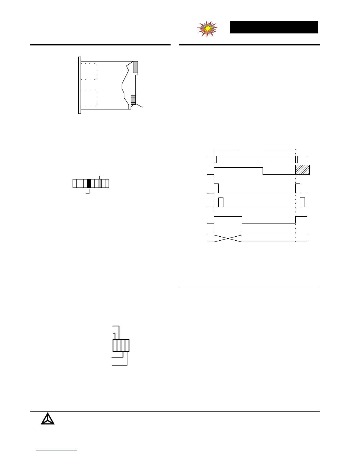
Scan Cycle
RPG Phase
NPN output ON
Bus
Scan Cycle
Trigger Delay Time
Data Read
Outputs Stable
Limits NPN output ON when
limits exceed setpoint
See
Note 1
Jumpers
Internal
Trigger
OR
External
Trigger
Input
Measure
Sense
Measure
Base
Data
Read
Output
Limit &
Analo
Outputs
Trigger Delay Time
(Determines Scan
Cycle Time when
using internal Data B & S Auto Restart
trigger) Ready 2 4 8
(default) 500us 110us 22us
*Special order, must
be set by factory
Note 1. When using an external trigger, the Scan Cycle Tim e i s
determined by the tim e between RPG transitions ( RPG NPN output
changes from OFF to ON). I f the time between transitions i s less
than the Trigger Delay Time, scan data will be lost.
S
B
NPN output ON
435us 110us 22us Yes
380us 110us 22us Yes
330us 110us 22us Yes Yes
275us 110us 22us Yes
220us 110us 22us Yes Yes
164us 110us 22us Yes Yes
110us 55us 22us Yes Yes Yes
*50us 25us 12us Yes Yes Yes
Delta Computer Systems, Inc.
email@deltacompsys.com http://www.deltacompsys.com
, 11719 NE 95th Street, Vancouver, Washington 98682-2444 (360) 254-8688 3
Page 4
CS2 Color Scanner
Base & Sense Limit Outputs
Limit outputs provide the means to control an external
device when the setpoints are exceeded. Each is an isolated
open collector NPN output. When the limit setpoint is met
(Base color above setpoint and Sense limit below setpoint),
the NPN output is turned ON. ON current is 1.6 mA
minimum, 8 mA typical. The maximum open collector
voltage is 30VDC.
Note: If the limit outputs are connected to a high speed
input, they may need to be qualified with the Data Ready
output.
Data Ready Output
The Data Ready output should be used when the CS2 is
connected to a fast Analog-to-Digital converter. Inaccurate
readings can result if the A-D tries to read the analog color
voltages at the same time that the CS2 is updating them. By
synchronizing the external A-D converter to the CS2's
scanning cycle, this problem is eliminated.
The Data Ready output varies with the scan time. When
scanning with the internal trigger, Data is valid (Data Ready
line OFF) for approximately 110 microseconds each scan.
For high scan rates, the Data Ready NPN open collector
load resistor may need to be lowered (below 2.7k). It is a
good idea to allow 20-50% margin for gain degradation of
the opto-coupler. The ON current is 1.6 mA minimum, 8
mA typical. The maximum open collector voltage is 30Vdc.
External Trigger Input
This input allows a scanning cycle to be started by an
external signal. It is particularly useful when the scanner is
connected up to an optimizing computer. When the
scanning cycle is initiated by a signal from a rotary pulse
generator (RPG) connected to a belt or other co nveying
system, the length of objects and features detected can be
determined by counting the number o f RPG counts that
occur while the object or feature is within view of the
scanner. In this way, dimensional information can be
obtained.
To use this option, jumper the scanner for external triggered
operation, and wire the output of the RPG (or other trigger
source) to the Trig In terminals. The trigger input of the
CS2 requires 5 mA and will work with signal sources
between 3.5 and 24V, ensuring compatibility with most TTL
and open-collector encoders.
Threshold Analog Inputs
The CS2 provides two analog inputs to control the Base and
Sense limit setpoints. For applications using these inputs,
please contact Delta for assistance.
Analog Outputs
The CS2 provides two analog outputs proportional to the
real time Base color and Sense color. These outputs are
updated every scan cycle. The outputs are 0-10V and will
drive high impedance inputs ( 2 kohms or higher).
When using the analog outjputs with a PLC or other
computer, the Sense reading is divided by the Base reading
to get the Sense/Base ratio. This ratio is then compared with
a threshold value as is done within the CS2.
However, using the analog outputs allows additional
flexibility, such as multiple thresholds, thresholds that can
be stored and set remotely.
Note that is is often advantageous to subtract the
background readings before calculating ratios in cases where
the object being viewed does not completely fill the viewing
area.
Contact Delta for help with specific applications.
Delta Computer Systems, Inc.
email@deltacompsys.com http://www.deltacompsys.com
, 11719 NE 95th Street, Vancouver, Washington 98682-2444 (360) 254-8688 4
Page 5
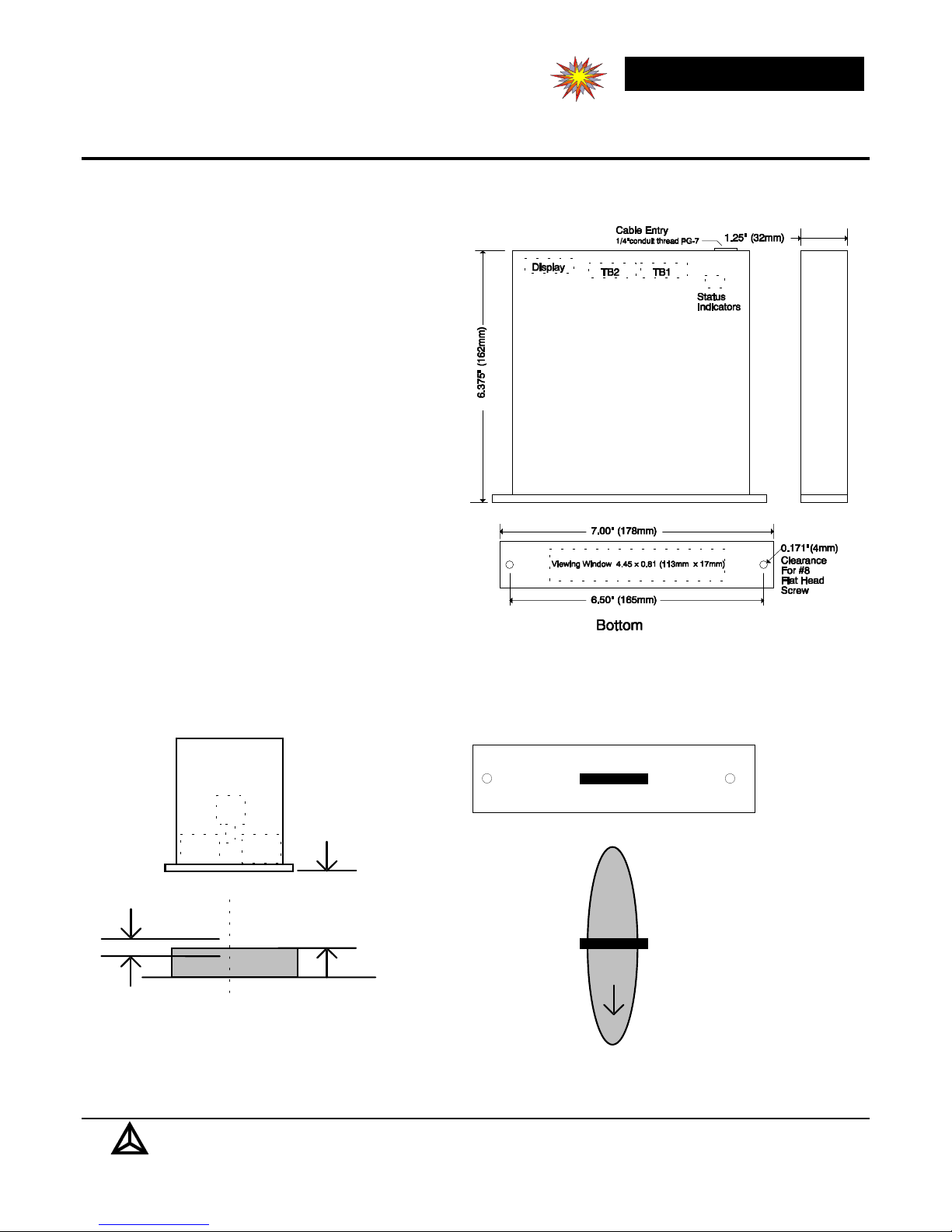
Mounting the CS2
j
The CS2 scanner is contained in a enclosure which has
mounting tabs on the bottom. The lighting LEDs shine
through the clear bottom and the optics pick up the
reflected light through the bottom also. The bar graph
display and status indicators can be viewed through the
clear top.
Mount the CS2 so that the object to be scanned is within
the scanning area. In the default configuration, the center
of the scanning range is 1.75" from the bottom of the
scanner. Although the CS2 can see to some extent from
about 1" to about 4", best performance is from 1.5 to 2".
The CS2 will operate in any position. However, in dirty
environments, it is best to have the CS2 lo oking straight
down, and worst to be loo king straight up. If the scanner
must be placed such that it is looking up, a stream of air
may be adequate to keep the window clean.
CS2 Color Scanner
It is also advantageous to be able to see the indicators
through the clear top of the unit when it is in operation.
CS2
Viewer
LEDs
Scanning Range
LEDs
Nominal Distance
from Scanner to
ob
ect
Object
Background
Scanning Area Line Orientation
P/N CS2-NR-A1X8-00
Bottom View of CS2
Object
Scanning Area
Various scanning areas and shapes are possible.
Please contact Delta for further information.
Delta Computer Systems, Inc.
email@deltacompsys.com http://www.deltacompsys.com
Top View of Scanned Area
, 11719 NE 95th Street, Vancouver, Washington 98682-2444 (360) 254-8688 5
Page 6
CS2 Color Scanner
y
y
gg
gg
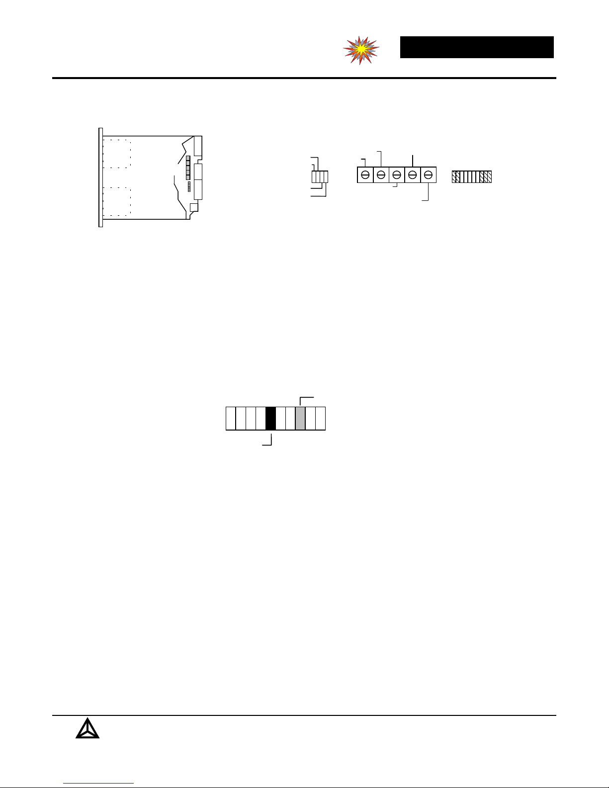
Wiring
The CS2 is designed to be wired using watertight flexible plastic conduit. In applications where sealed operation is
unnecessary, the wires can be run out through a strain relief connector. The conduit can also be used to pressurize the CS2
with low pressure, dry air for additional protection.
The number and type of wires required depend on the mode of operation. Only two wires, for 24Vdc power, are required to
operate the device. In simple applications, two more wires are used for the output. A four wire cable with an overall shield is
fine.
If analog threshold inputs or color outputs are used they need to be run through individually twisted, shielded pairs.
General Wiring Guidelines
1. The CS2 has sensitive circuitry which can be affected by electrical noise generated by loads. Its power supply should not
be used to power other loads.
2. The output of the 24Vdc sensor power supply must be isolated from earth ground. The CS2's common is connected to
earth ground through its case.
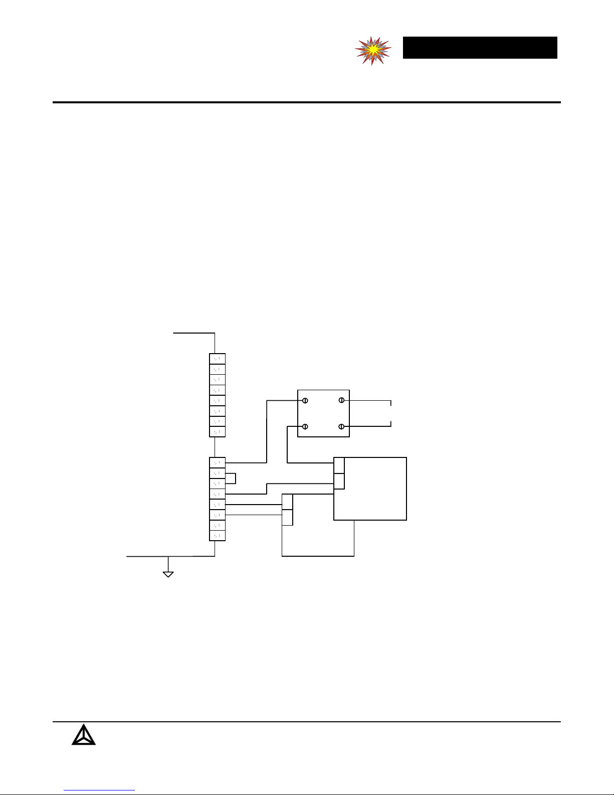
Application using Sense and Base Limits Outputs for Sorting or Rejecting Objects
CS2
Sense Threshold
Base Threshold
Common
Sense Color
Base Color
Common
Data Read
Data Read
Sense Limit Sense Limit +
Base Limit Base Limit +
Common
24V +
External Tri
External Tri
er er +
Case
In this application, the
CS2 is used in its
default configuration
(internal trigger, darker
+
SSR Load
-
-
+
areas to be sorted or
rejected, object scanned
every 500uS). In order
to activate the solidstate-relay (SSR), the
object in the scanning
- Output
+
Phoenix
- Sensor
Power
+
24Vdc
Phoenix
CM 90-PS-110 AC/24
Order No. 2943408
or equiv.
CM 90-PS-110 AC/24
Order No. 2943408
or equiv.
Power
24Vdc
area must cause the
Base color to exceed
the Base Threshold
(object present)
and
the
Sense color must be
below the Sense
Threshold (Low Ratio).
Delta Computer Systems, Inc.
email@deltacompsys.com http://www.deltacompsys.com
, 11719 NE 95th Street, Vancouver, Washington 98682-2444 (360) 254-8688 6
Page 7
CS2 Color Scanner
y
y
gg
gg
y
y
gg
gg
q
q
g
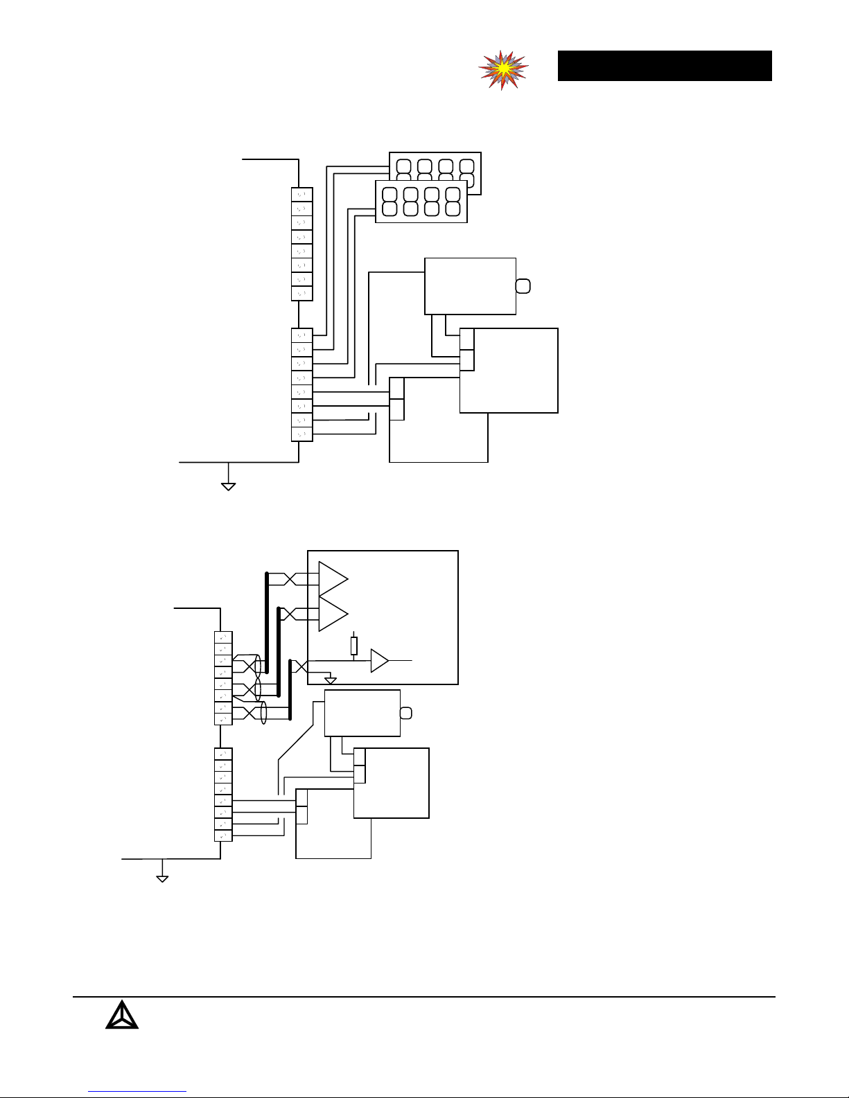
Using the CS2 With a Rotary-Pulse-Encoder (RPG) for Counting Objects and Defects
Defect Counter
To synchronize CS2's
scan with an external
event, use the external
trigger input. In this
example, a new scan is
started every time a
pulse is received from
the RPG. The Sense
Limit output is used to
count the number of
dark areas (defects)
seen, while the Base
Limit output is used to
count the number of
objects.
CS2
Sense Threshold
Base Threshold
Common
Sense Color
Base Color
Common
Data Read
Data Read
Sense Limit -
Sense Limit +
Base Limit Base Limit +
Common
24V +
External Tri
External Tri
er er +
Case
Object Counter
Phase A
+
Open Collector
NPN
RPG
+
-
-
+
Phoenix
- Sensor
Power
+
24Vdc
Phoenix
CM 90-PS-110 AC/24
Order No. 2943408
or equiv.
CM 90-PS-110 AC/24
Order No. 2943408
or equiv.
Output
Power
24Vdc
Sense Threshold
CS2
External Tri
External Tri
Base Threshold
Common
Sense Color
Base Color
Common
Data Read
Data Read
Sense Limit Sense Limit +
Base Limit Base Limit +
Common
24V +
er er +
Case
Example Using the CS2 with an Optimizing Computer
Optimizing Computer
+
-
Isolated Differential
Analo
5V
2.7K
Phase A
Open Collector
NPN
RPG
-
+
-
+
Phoenix
CM 90-PS-110 AC/24
Order No. 2943408
or e
Inputs 0-10Vdc
A/D
Trigger
TTL or CMOS
Output
Power
24Vdc
uiv.
+
-
+
+
-
-
+
+
+
-
- Sensor
Power
+
24Vdc
Phoenix
CM 90-PS-110 AC/24
Order No. 2943408
uiv.
or e
In applications that require more sophisticated
filtering, thresholds, or limit algorithms, CS2's
analog outputs and inputs provide an easy interface
to an optimizing computer. As shown, the analog
outputs are read each time the Data Ready isolated
NPN output goes from ON to OFF. The
optimizing computer then processes the analog
information. Remember, the analog data provided
by the CS2 is not absolute color information, but
relative values.
In this example the Base and Sense Threshold
analog inputs are not used. If desired, these can be
used to control of the Base and Sense Limits
setpoints. By controlling the se tpoints, the
optimizing computer can use the CS2's two
isolated NPN outputs for control. Contact Delta
for additional information.
Delta Computer Systems, Inc.
email@deltacompsys.com http://www.deltacompsys.com
, 11719 NE 95th Street, Vancouver, Washington 98682-2444 (360) 254-8688 7
Page 8

Configuration
gg
gg
g
gg
gg
g
2
4
8
Internal Tri
External Tri
Hi
h Ratio
Low Ratio
er
er
LED's
LED's
Internal Tri
External Tri
Hi
Low Ratio
Configuration
Jumpers
Default Jumper Configuration
2
4
8
er
er
h Ratio
Bar Graph
TB2
TB1
Status
Indicators
CS2 Color Scanner
Sense Low/High Ratio
The Sense Limit is jumper configurable to respond to
either Sense/Base ratios that are lower than normal (Low)
or Sense/Base ratios that are higher than normal (High).
Example applications where the Dark setting (default) is
used including detecting green areas on carrots, knots on
wood and burnt cookies, while the High setting would be
used to detect white ends on asparagus, some paint
applications, etc.
External and Internal Triggers
When using the Internal trigger (default), every 500
microseconds the CS2 automatically takes new Sense and
Base color readings, calculates averages and Sense/Base
ratio and updates the outputs and indicators.
If an external trigger is desired, move the jumper from the
internal trigger position to the external trigger position and
wire the output of the RPG (or other trigger source) to the
Trig In terminals located on TB1.
Delta Computer Systems, Inc.
email@deltacompsys.com http://www.deltacompsys.com
, 11719 NE 95th Street, Vancouver, Washington 98682-2444 (360) 254-8688 8
Page 9
CS2 Color Scanner
y
y
y
g
Adjustments
The CS2 has five potentiometers (pots): LED Time, Overall Gain, Sense Match, Base Threshold, and Sense Threshold. The
LED time adjustment is not used for basic operation; contact Delta for more information
LED's
LED's
Trim Pots
Output
Bar Graph
TB2
TB1
Status
Indicators
Data Read
Trig In
Base Limit
Sense Limit
Status Indicators
Overall Gain
Led Time
Sense Match
Sense Limit Threshold
Base Limit Threshold
Yellow
Output Bar Graph
Red
Green
Displa
The procedure below is for applications where the background (with no object present) is dark compared to the objects to be
viewed and the features to be identified are relatively dark (in the Sense color spectrum) compared to the object. Examples
include green areas on carrots, knots on wood and burned cookies.
Gains and Thresholds
1. Mount and wire the unit and connect power. The lighting LEDs on the bottom of the CS2 and the Data Ready indicator
should come on when power is applied. The output bar graph display may or may not be lit.
2. Find a sample object with the greatest reflectance (biggest and lightest). Put it in the viewing area and adjust the Overall
Gain until the less intense bar graph indicator is in the 8th or 9th p osition (red).
Output Bar Graph Displa
Green
Less intense bar indicates Base Color
ht bar indicates Sense Color
Bri
Yellow
Red
3. Adjust the Sense Match pot until the bright bar graph indicator is on to p of the less intense bar graph indicator (8th or 9th
position).
4. Put an average object in the viewing area. Both base color and sense color bar graph indicators should be within the
center of the display (green).
5. Remove all objects. Reflected light from background should display no higher tha n the second bar graph indicator
(yellow).
6. Place an average size and color object in the viewing area for about ten seconds. Remove all objects and then
immediately put a minimum size, normal color object in the viewing area. Adjust the Base Threshold pot such that the
Base Limit indicator is just activated.
7. Put a marginally nominal object in the viewing area (make sure the low/high ratio limit configuration jumper setting is
correct). Adjust the Sense Threshold pot such that the sense limit indicator is just activated.
8. Fine tune both threshold adjustments while observing on-line operations.
Delta Computer Systems, Inc.
email@deltacompsys.com http://www.deltacompsys.com
, 11719 NE 95th Street, Vancouver, Washington 98682-2444 (360) 254-8688 9
Page 10

CS2 Color Scanner
Color Tolerances
You want a bunch of paperweights in the shape of our logo.
You sketch the thing, add dimensions, and send it off to a
turn-key manufacturing shop with these instructions:
Dimensions: ±0.035"
Weight 1 LB, ±1 oz.
Color: Red; just like the sample.
To keep costs down, you've given generous to lerances on
dimensions and weights, but what is your color tolerance?
The manufacturer might think he's got an exc ellent match,
and you might think it clashes terribly. It ge ts worse. If you
are matching items that are not colored the same way, such
as plastic and metal, you have to take into account the
lighting as well.
Most colors are made up of a mixture of pigments and can
look very different under varied lighting. Different
pigments are used for paints, plastics, inks, dyes, etc.
Perfect matches of diffe rent materials under varie d lighting
conditions is virtually impossible.
So how do you express color tolerances? Color can be
expressed in mathematical terms; intensity, hue, etc., and
can have mathematical tolerances, but this will seldom
produce optimum results.
Why is that? In order to keep manufacturing costs d own,
tolerances should be as wide as possible. But color
tolerances are based on perception, and are not evenly
distributed. In most cases, larger variations in intensity are
permissible than in hue.
The pencils travel lengthwise, erasers first, under the CS2
which is configured for a viewing area of 1/32" by 1/2". A
rotary pulse generator (RPG) provides a pulse for every
1/32" of pencil travel so that the entire top side of pencil is
examined. The CS2 is triggered from this RPG.
The optimizing computer reads the raw analog color
information, subtracts the average background intensity, and
determines when a pencil is in the viewing area -- Base color
amplitude 15% or more than average Base amplitude, pencil
length -- counts RPG pulses while Base amplitude is high,
eraser present -- counts RPG pulses while Sense/Base ratio
is 110% or more than average Sense/Base ratio at the
beginning of the pencil, paint present -- checks that
Sense/Base ratio does not go high again during remainder of
the pencil length.
The system was set up, adjusted and it ran great. Except,
after maintenance shutdowns. Sometimes it would just
ignore the pencils.
A little troubleshooting pinpointed the prob lem. During
maintenance, the machine was cleaned using air nozzles.
The fine sawdust settled everywhere, including on the pencil
conveying belt. The sawdust was light colored and highly
reflective, making the background intensity readings as high
as the pencils!
A simple continuous belt cleaning system took care of the
problem.
Tolerances in hue are often not even. Butter, for example
can be quite orange without cause for concern, but even
slightly green butter is likely to be repulsive.
Creating a multidimensional tolerance color model is
possible, but would take a lot of time. Even if you went to
this expense, on line, high speed testing against this model
would be very expensive.
In short, color is a perception issue, and is still more of an
art than a science. Fortunately, in many real-world
situations, a one dimension test for color is all that is
required; green areas on carrots, white ends on asparagus,
dark knots on wood, paint either there or not there, etc.
These types of applications are suited to the CS2 scanner.
Pencil Sorting Example
In this hypothetical application, red pencils are being
examined for missing erasers and missing paint. The CS2 is
used with an optimizing computer in order to make length as
well as color decisions on the product.
Delta Computer Systems, Inc.
, 11719 NE 95th Street, Vancouver, Washington 98682-2444 (360) 254-8688 10
email@deltacompsys.com http://www.deltacompsys.com
Page 11
CS2 Color Scanner
Putting It To Work
Comparing Colors
The CS2 is primarily intended for use in applications where
objects are 100% scanned for a deviation in average or
normal color, whether the deviation is a defect or a feature
that needs to be recognized.
It is possible to compare against a sample and activate the
limit outputs based on deviation from a sample.
Consider the hypothetical case where paper is being
manufactured for manila envelopes.
Currently, samples are taken to the lab on a regular basis and
tests are conducted to determine if the paper has the proper
beige color. The problems with the current system is that
the paper machines run continuously and at a rate that makes
it unfeasible to take samples often. On the other hand, if the
paper color goes out of spec., a tremendous amount of waste
can be created before the problem is identified and
corrected.
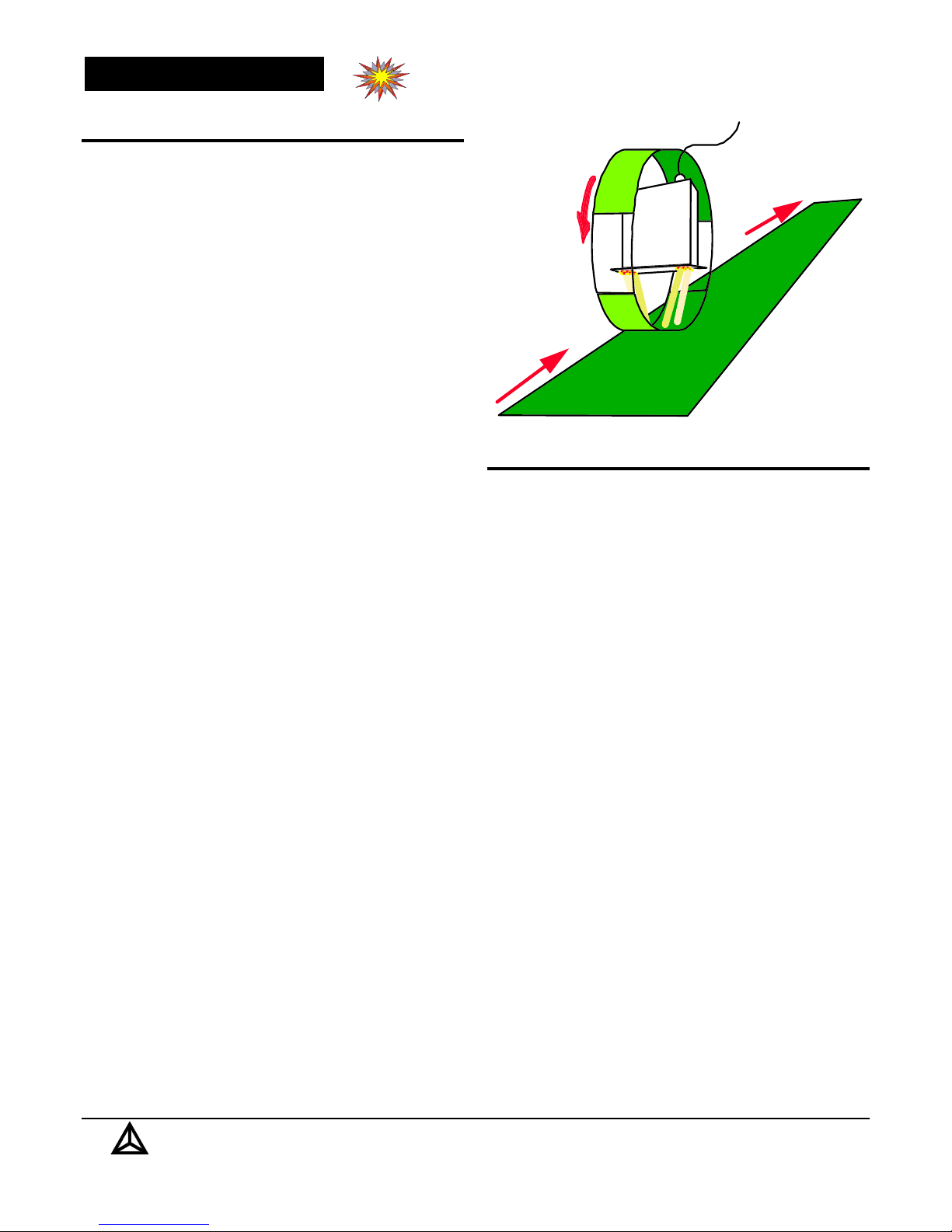
A CS2 was mounted above the flow of paper (web) inside of
a special wheel. One-half of the area of the wheel was
removed and the inside of the other half covered with a labtested sample of the paper. The wheel is mounted just above
the web and rotated at the same speed as the web. The CS2
alternately looks at the web and the sample paper.
In this special case the concepts of Base color and Sense
color do not apply. Instead the CS2 colors were chosen to
correspond to the colors of the various dyes used in the
paper, and the outputs analyzed for differences between the
sample and the web.
Traversing Heads
In the case of slow moving lineflow (baked goods, for
example), a 100% inspection can be done using a CS2 and a
traversing mechanism.
The outputs of the CS2 are connected to a controlling
computer which also reads the position of the CS2 as it is
moved back and forth across the lineflow.
A traversing head can also extend beyond the lineflow to
check against a reference color, as in the previous manila
envelope example.
The paper is still lab tested, but now, with the on-line
inspection, out-of-spec. color conditions can be found and
corrected immediately.
Delta Computer Systems, Inc.
, 11719 NE 95th Street, Vancouver, Washington 98682-2444 (360) 254-8688 11
email@deltacompsys.com http://deltacompsys.com
Page 12

CS2 Color Scanner
Application Guidelines
Power Supplies
The silicon cell used in the CS2 is electrically connected to
its metal package which is connected to the CS2's metal
enclosure. Therefore the CS2 must be connected to a good
ground, preferably the same ground as the machinery around
it, and the signals from the CS2 isolated. The CS2 must be
powered by a dedicated power supply, and the optional
analog inputs and outputs must be isolated if they are used.
The Limit outputs are isolated in the CS2.
Electrical noise
The signal level from the silicon cell is low and is amplified
by high speed circuitry. This circuitry is sensitive to
electrical noise from intense electrical fields. The CS2's
metal enclosure is an adequate shield against most electrical
interference. Use high quality shielded cable to reduce
electrical noise. If analog inputs or outputs are used, they
should be wired using individually shielded, twisted pairs.
Data Skew
The CS2 reads colors one at a time, in sequence. The Base
color is captured 22 microseconds after the Sense color. If
an object is moving while it is scanned, the information from
the two colors will be skewed slightly. If an abrupt change
in data occurs, the Sense/Base ratio will be momentarily
incorrect. Usually this will not cause any problems. If it is a
problem, it can be filtered out, either electronically in standalone applications or with a software filter when used with a
computer. The data skew can also be reduced by decreasing
the LED time (contact Delta for more information).
Color Errors
The CS2 uses an unfiltered silicon cell which captures all
reflected light. It determines color by turning on only the
desired color at a given time. The wavelength of the LED
lighting is a function of the LEDs. This wavelength varies
slightly with temperature.
Ambient light, or any other extraneous light, is an error
source. The CS2's LEDs are very bright, so reasonable
amounts of ambient light can be tolerated. (Don't be fooled
by the apearance of the CS lighting. The LEDs are only on
about 5% of the time. Your eyes average this light, making
it appear 20 times less intense.)
Background Errors
In order to see o bjects, it is necessary to distinguish the m
from the background. To maintain a good contrast, the
background should be black in the color spectrum of
interest. If the background is paintable, a flat black paint
such as Krylon 1602 can be used. Most black belting is also
acceptable. Wet or otherwise reflective surfaces actually
produce low backgr ound readings as long as light cannot
reflect directly back into the viewer.
Because the light from the CS2 tends to dissipate in all
directions, increasing the distance from the CS2 to the
background will reduce the background readings. If this is
done, be sure the increased distance does not allow ambient
light to become a problem.
Usable results can sometimes be obtained even if the
background cannot be made totally black. Ho wever, the
object signal should be at least twice as strong as the
background signal. The background will also contribute
more errors if the Sense/Base ratio of the background is very
different from the Sense/Base ratio of the objects. If this is
the case the background signal must be reduced to an
insignificant level.
Reflections
When either the CS2 lighting or ambient light is allowed to
reflect directly into the scanner it will overdrive the circuitry
and cause meaningless outputs. Usually this condition can
be avoided by controlling the relative angle of the scanner to
the objects and background.
In some applications it is impossible to avoid an occasional
reflection. In these cases, an external optimizing computer
can be used to "trap" the overdrive readings and ignore
them. This technique avoids making decisions on bad data,
but the overdriven data are still lost.
Intensity Variations
The CS2 lighting pattern is made up of multiple LEDs; some
variation in intensity is to be expected. The larger the
viewing area, (length, width, and depth), the more intensity
variation will occur. The LEDs used in the CS2 are
specially selected and the light pattern is optimized at the
factory. The default configuration pattern is optimized for
low ratio limit operation. The light pattern is adjusted such
that objects outside the specified viewing area but still
within the lighting area will not be read as having low
Sense/Base ratios, thus eliminating false limits. If needed,
other light pattern optimization techniques can be used.
Using Multiple CS2s
The scanning area of the CS2 is limited to about 1.25" by
the lighting. However, multiple CS2s can be used to cover a
wide area. Care must be taken to avoid interference between
the units. This is easily accomplished by either physical
Delta Computer Systems, Inc.
email@deltacompsys.com http://www.deltacompsys.com
, 11719 NE 95th Street, Vancouver, Washington 98682-2444 (360) 254-8688 12
Page 13

spacing or controlling the scans. If CS2s are mounted such
that the light from one does not extend into the other's
viewing area, then they will not interfere with each other.
In multiple unit applications, it is often advantageous to
have the units next to each other so that they take up as little
space as possible. The light from each unit will extend into
the adjoining unit's viewing area. In this case, interference
can be avoided by using the External Trigger mode and
triggering adjacent units at different times. A separation of
50 microseconds is sufficient. In applications which use a
quadrature output rotary pulse generator, this can be done by
connecting ajacent units to the other output phase, i.e.
scanners 1, 3, 5, etc. to phase A and scanners 2, 4, 6, etc. to
phase B.
If large numbers of units are requir e d, you may want to
consider a custom scanner. Multiple units can be packaged
into a single enclosure, resulting in a cleaner package. Units
can also be packaged around a tube, etc. Contact Delta for
details.
CS2 Color Scanner
Delta Computer Systems, Inc.
email@deltacompsys.com http://www.deltacompsys.com
, 11719 NE 95th Street, Vancouver, Washington 98682-2444 (360) 254-8688 13
Page 14

CS2 Color Scanner
Technical Information
Base and Sense Color
Light Source Options
Stand Off Distance
Scanning Range
Scanning Area
Response Time
Operating Modes
Two Analog Outputs
(Base and Sense)
Two Analog Inputs
(Base and Sense Threshold)
One Digital Input
(External Trigger)
Three Digital Outputs
(Data Ready, Sense
and Base Limit)
Supply Voltage
Blue, green, yellow, orange, red, and
near-infrared (450nm to 950nm)
1.75 inches (44.5mm); configurable to six inches
±0.25 inches (6.4mm); configurable to ±2 inches
0.04 x 0.33 inches (1mm x 8mm); configurable
to 2 inches. Various shapes and sizes available
50us
Continuous or External Trigger
0-10 volts at 5 mA maximum
0-10 volts, input impedance minimum of 50k
Optically isolated, 3.5 - 24 volts, 5 mA minimum
Optically isolated, TTL/CMOS compatible;
1.6 mA minimum, 8 mA typical; 30 volt
maxi mum
24 VDC (±5%)
Ω
Current Consumption
Enclosure
250 mA maximum
Extruded aluminum, optional NEMA 4X
Ordering Information
License agreements provide Delta with the exclusive rights to use the CS2 technology in all applications outside of frozen
potato processing. If you have any questions, please ask a Delta representative.
Company Profile
Delta Computer Systems, Inc. manufactures color scanners, motion controllers a nd other industrial controls providing high
performance automation solutions to a wide range of industries.
Delta Computer Systems, Inc.
, 11719 NE 95th Street, Vancouver, Washington 98682-2444 (360) 254-8688 14
email@deltacompsys.com http://deltacompsys.com
Page 15

CS2 Color Scanner
General Application Information
The term "color" actually inplies visable light -wavelengths from about 400 nm (violet) to about 750 nm
(deep red), although in this document any color that can
be seen by the CS2 is refered to as a color.
With high intensity LEDs available at 450nm (blue) and at
a variety of wavelengths up to 700nm, the CS2 can see all
of athese colors. But the CS2's capability does not stop
there; the precision silicon photodiodes in the CS2 can see
into the near-infrared (NIR) up to about 1,000nm, and
LEDs are readily available in this region as well.
NIR LEDs are used in the CS2 and similar scanners for
several different functions. One involves using the NIR
reading to establish a baseline value that is constant (or
nearly constant) regardless of the visible color of the
product.
For example, to detect "browness" on cookies, any one of
several visable colors can be used. But using one color
(monochromatic) and looking for changes in amplitude
will not produce good results, since other factors, such as
dirty optics, temperature changes, etc., can produce
signals that are indistinguishable from "browness"
changes.
However, using the ratio of a visable color to an NIR
color will give the desired result: the ratio will only
change with product color, not with ambient conditions.
Here are some examples of items and applications that
Delta has successfully tested:
•
Detecting the presence or absence of brown glue on
brown wood
•
Detecting "browness" of crackers, etc.
•
Detecting green ends on carrots
•
Detecting white ends on asparagus
•
Detecting various defects on potatoes
•
Differentiating between tomatoes and MOT (material
other than tomatoes)
•
Using a modified CS2, differentiating between
several different colors of cloth
•
Using a modified CS2, ide ntifing several different
colors on a cardboard box
•
Some of these applications are in use, and some
remain in testing. More tests are done on a regular
basis.
Other uses of the NIR spectrum include sorting items that
can be differentiated in the NIR spectrum. Delta's CSplus-T50 tomato sorters, for example, uses two different
NIR colors to differentiate tomatoes and virtually any
other item.
Delta's LGM length graders use monochromatic NIR light
to detect product presence only. They function as
reflective light curtains and detect products regardless of
visable color. The viewing area is very long and narrow
allowing the LGM to cover an area approximately two
inches in diameter at about six inches from the scanner.
The LGM measures product length at 1/32 inch resolution
at speeds of 550 ft/min.
Delta Computer Systems, Inc.
, 11719 NE 95th Street, Vancouver, Washington 98682-2444 (360) 254-8688 15
email@deltacompsys.com http://deltacompsys.com
 Loading...