

Page 1

Delta Fan/Pump Vector
Control Drive
CP2000 Series
Quick Start Guide
www.deltaww.com
Page 2

Warning! T
his is a short guide, and does not give all necessary safety information.
Refer to the CP2000 Series User Manual for all safety information to avoid
damage to the drive, motor or personal injury.
Document Version 1.0
Published August 25, 2017
Page 3

Table of Contents
CHAPTER 1 INTRODUCTION .................................................................................................. 3
1-1 Before You St art ............................................................................................................... 3
CHAPTER 2 CONTROL WIRING .............................................................................................. 4
2-1 Cabling ............................................................................................................................. 4
CHAPTER 3 SET UP THE VFD P ARAMETERS ....................................................................... 5
3-1 About Parameters ............................................................................................................ 5
3-2 VFD Digital Keypad .......................................................................................................... 5
3-3 Digital Keypad Keys ......................................................................................................... 6
3-4 Display Workflow .............................................................................................................. 7
3-5 Setting Up Parameters for the First Time.......................................................................... 7
Changes to System Parameters (00) group ........................................................................ 8
Changes to Basic Parameters (01) group ........................................................................... 9
Digital Input / Output Parameters (02) group ......................................................................10
Motor Parameters (05) group .............................................................................................10
Special Parameters (07) group ..........................................................................................11
Communication Parameters (09) group .............................................................................12
CHAPTER 4 START UP TEST .................................................................................................14
APPENDIX A PUBLICATION HISTORY ..................................................................................15
Page 4
Chapter 1 Introduction
Chapter 1 Introduction
This Quick Start Guide shows you how to configure the CP2000 Series drive settings to work
with your Delta Controls controllers. The guide assumes the drive has already been installed onsite by a qualified technician.
Refer to the CP2000 Series User Manual for more information about how to
unpack (Chapter 3), install (Chapter 2) and wire the drive (Chapter 4 and 5) to its
power supply.
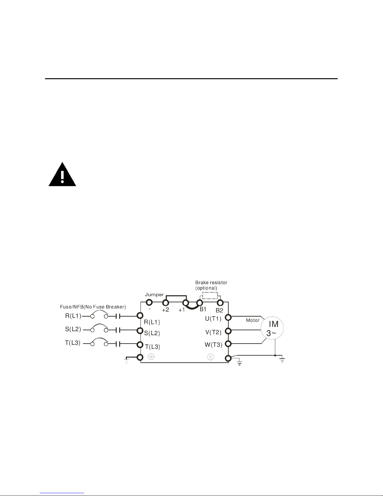
1-1 Before You Start
Verify the following wiring setup before you turn on the VFD for the fi rst time.
• Make sure the line voltage (L1/L2/L3) is not connected to the output terminals (U/V/W) of
the VFD.
• Ensure the motor is connected to the drive before applying power to the VFD.
3
Page 5

Do not remove the factory jumpers between STO1/STO2/+24V and
Chapter 2 Control Wiring
Chapter 2 Control Wiring
SCM1/SCM2/DCM.
Make sure the AFM1 and AVI1 switches are in the 0-10V position.
Make sure the Start Relay shown is not in a closed state when the drive is initially
powered up.
For the conventional start/stop, speed control and speed feedback via hard-wired I/O, the
following wiring terminations are required:
• Start/Stop: Control relay contacts wired between FWD and DCM.
• Speed Control: 0-10V speed control is connected to AVI1 (+) and ACM (-).
• Speed Feedback: 0-10V speed status is connected to AFM (+) and ACM (-).
2-1 Cabling
The analog speed signals should be using shielded cable.
4
Page 6

Chapter 3 Set Up the
VFD Parameters
Chapter 3 Set Up the V FD Parameters
This section describes how to set up the VFD parameters when you turn on the drive for the first
time, and how to use the digital keypad on the VFD to access these parameter settings.
3-1 About Parameters
The VFD parameters are organized in groups which are numbered from 00 to 13. Members in
the same group share a common prefix (00 to 13) and each parameter member is identified by
a unique number. The parameters and their settings are accessible on the keypad main menu
by selecting Parameter Setup.
For example, the group Basic Parameters share the prefix “01” and “01-00” is the maximum
operation frequency parameter.
See Chapter 11 and 12 in the VFD-CP2000 User Manual for more details about
the parameters and their factory settings.
3-2 VFD Digital Keypad
The digital keypad consists of keys and a display screen. This section only applies to the KPC
CC01 keypad.
See Chapter 10 in the VFD-CP2000 User Manual for more information.
5
Page 7

Chapter 3 Set Up the VFD Parameters | CP2000
Key
Description of Function
RUN
When the VFD is in HAND mode, pressing RUN starts the motor.
STOP/RESET
This key has the highest processing priority in any situation.
will clear an outstanding Fault.
FWD/REV
Used to reverse the rotation direction of the motor. Not used in
HVAC applications.
HAND
Pressing HAND puts the VFD into local control mode, where remote
control the speed using the keypad.
AUTO
Pressing AUTO puts the VFD into remote control mode, which can
in AUTO.
MENU
Press MENU to open or return to the main menu that lists 13
options, including Parameter (Pr) Setup and Display Setup.
ESC
Press ESC to leave the current menu and go back up one level in
any change to the value.
ENTER
Press ENTER to go to the next level in the menu. It will also apply a
change to a parameter whose value has been altered.
These keys perform two functions, depending on the state of the
these keys can be used to adjust the running speed of the drive.
F1, F2, F3, F4
These keys are not used by default, but can be customized to
perform application specific functions.
3-3 Digital Keypad Keys
Pressing STOP stops the VFD whether the VFD is in HAND mode or
AUTO mode. Once the drive has stopped, pressing STOP/RESET
signals are ignored. "HAND" displays on the keypad screen.
While in this mode, it is possible to start the VFD and to manually
be either hardwired I/O or BACnet control. "AUTO" displays on the
keypad screen. The local RUN and speed control is displayed while
the menu. It will also leave any parameter viewed without making
display. When in the menu, and scroll through the different
menu levels and parameters. When a single parameter is being
adjusted, and determine which digit of the setting will be
adjusted when you use and . On the display’s main page,
6
Page 8

3-4 Display Workflow
3-4 Display Workflow | CP2000
3-5 Setting Up Parameters for the First Time
This section describes how to configure the drive correctly after turning it on for the first time.
To access the VFD parameters on the keypad display,
1. Push the MENU button on the keypad.
2. Scroll through the menu using and to select 1. Pr Setup and press ENTER.
Parameter (Pr) Setup is a menu option that allows you to change the drive’s setup
parameters. The parameters are organized as groups under Parameter Setup, from
System or Drive Parameters (00) to Industry Application Parameters (13).
3. Scroll through the list using and to select the parameter group you want to
modify. Press ENTER to view the parameters in the selected group.
4. Use and to select the parameter you want to modify. Press ENTER to go to the
parameter’s option menu.
5. To select a number that represents the option you want to set, use and .
7
Page 9

Chapter 3 Set Up the VFD Parameters | CP2000
Parameter
Display Text
Description of Parameter
Default
Value
Preferred
Value
00-20 Source of
Source of
The source of frequency
hardwired I/O control)
0
2
00-21 Source of
Source of
This determines which
5 - not used
0
1
00-22 Stop
Stop Methods
This determines what the
for HVAC)
0
1
To enter a value, use and to increase or decrease the number displayed. In
some cases when you are presented with a string of numbers, decimal places, dates or
times, you may need to use and to move the cursor’s position to make a specific
change.
6. Press ENTER to save the option or changes you’ve made. Use ESC button to go back
up one level in the menu, or push MENU to return to the main menu.
7. Use steps 3 to 6 to make the required changes to the parameters listed below.
The following tables list the parameters that you need to set up and their recommended values.
Changes to System Parameters (00) group
frequency
operation
FREQ
OPER
parameter determines which
control signal controls the
drive's frequency in AUTO
mode.
Parameter options:
0 - Keypad (not
recommended)
1 - RS-485 BACnet
2 - Analog Input (used for
control signal starts or stops
the drive in AUTO mode.
Parameter options:
0 - Keypad (not
recommended)
1 - Hardwired I/O Terminals
2 - RS-485 BACnet
3 - not used
4 - not used
method
drive does when
commanded to stop.
Parameter options:
0 – Ramp to stop
1 – Coast to stop (preferred
8
Page 10

3-5 Setting Up Parameters for the First Time | CP2000
Parameter
Display Text
Description of Parameter
Default
Value
Preferred
Value
00-32 Keypad
KPD STOP
This determines whether the
(preferred for safety)
0
1
Parameter
Display Text
Description of Parameter
Default
Value
Preferred
Value
01-11 Output
Lower Bound
This determines the
prevent motor overheating.
0.00 Hz
10-15 Hz
01-12
1st ACC Time
This is the time, in seconds,
too low.
10 secs
60 secs
01-13
1st DEC Time
This is the time, in seconds,
centrifugal fans.
10 secs
60 secs
stop function
ENABLE
STOP key on the keypad is
active when the drive is
running in AUTO mode.
Parameter options:
0 – STOP key disabled.
1 – STOP key enabled
Changes to Basic Parameters (01) group
frequency lower
limit
Acceleration time
1
FREQ
minimum speed of the drive
motor. It is important that
this speed is not too low to
for the drive to ramp up from
0 Hz to 60 Hz. It's important
that this time is not too fast,
or an overload fault will trip.
The factory default time is
Deceleration time
1
for the drive to ramp down
from 60 Hz to 0 Hz. If this
time is set too low, an OVN
fault will occur. The factory
default time is too low for
large inertia loads like
9
Page 11

Chapter 3 Set Up the VFD Parameters | CP2000
Parameter
Display Text
Description of Parameter
Default
Value
Preferred
Value
02-35 External
Fault Reset OP
When s et to 1, th e drive
recommended).
0
1
Parameter
Display Text
Description of Parameter
Default
Value
Preferred
Value
05-01 Full load
Motor 1 Rated
This determines the full load
None
As stated
nameplate.
05-02 Rated
Motor 1 Rated
This determines the motor
None
As stated
0.746
05-03 RPM of
Motor 1 Rated
This determines the motor’s
1710 RPM.
motors.
As stated
nameplate.
05-04 Number of
Motor 1 Poles
This determines the motor’s
8 – 900 RPM
4, which is
RPM value
Digital Input / Output Parameters (02) group
operation after
reset and activate
Motor Parameters (05) group
current of motor
power of motor
A
P
automatically restarts after a
power failure, assuming the
FWD terminal is still closed.
When s et to 0, th e drive
powers up again and stops,
requiring a cycle of the Start
signal (turn off and then turn
on again) to resume normal
operation (Value 0 is not
rating of the motor in amps.
power in kW.
on the
motor
on the
motor
nameplate.
Note: kW
= HP *
motor
poles in motor
60Hz RPM.
number of poles.
Parameter options:
2 – 3600 RPM
4 – 1800 RPM
6 – 1200 RPM
10
This is fine
for 4 pole
correct for
~1800 RPM
motors.
on the
motor
as stated
on the
motor
nameplate.
Page 12

3-5 Setting Up Parameters for the First Time | CP2000
Parameter
Display Text
Description of Parameter
Default
Value
Preferred
Value
07-06 Restart
Momentary
The operation mode when
minimum frequency
0
1
07-07 Maximum
Power Loss
The duration of the period of
seconds.
2 secs
20 secs
07-10 Restart
Fault Re-RUN
This determines what the
minimum frequency
0
1
07-11 Number of
Auto Restart
The number of times the
Range is 0 to 10 times.
0
1 or more
Special Parameters (07) group
Setting up these parameters is optional but useful to minimize efforts to correct drive faults.
after momentary
power down
power loss
duration
after fault
Power
Time
Way
the AC motor drive restarts
from a
momentary power loss.
Parameter options:
0 – Stop operation
1 – Speed search start, at
the current speed
2 – Speed search start, at
power loss in seconds
before the drive will stop
operation.
Range is between 2 to 20
drive does after a fault
occurs.
Parameter options:
0 – Stop operation
1 – Restarts automatically,
speed search starts with
current speed
2- Restarts automatically,
speed search starts with
auto restarts
drive can restart
automatically after a fault.
11
Page 13

Chapter 3 Set Up the VFD Parameters | CP2000
Parameter
Display Text
Description of Parameter
Default
Value
Preferred
Value
07-12 Speed
Restart Method
This determines how the
from minimum frequency.
0
3
07-33 Auto
Reset
When a r estart occurs after
intervention.
60 secs
60 secs
Parameter
Display Text
Description of Parameter
Default
Value
Preferred
Value
09-31 Internal
COM1 Protocol
Set up the protocol
1 – BACnet MS/TP
0
1
search on startup
restart internal of
fault (Internal
time counter for
faults)
RestartCNT
drive starts the motor. This is
a useful setting if the drive
occasionally starts when the
motor is already spinning.
Parameter options:
0 – Disable. Wait for the
motor to stop spinning
before next start.
1 – Speed search, starting
from maximum frequency
(normally 60Hz).
2 – Speed search, starting
from motor start frequency
(normally 0.5Hz).
3 – Speed search, starting
a fault, the drive starts this
internal time clock and
counts the number of faults
that occur within this time
period. If the number of
faults do not exceed the
number recorded in the 0711 parameter, the time clock
and fault are reset back to
zero.
When the number of faults
exceed the 07-11 parameter
value, the drive faults and
stops, requiring user
Communication Parameters (09) group
These parameters are only necessary if you are planning to communicate to the built-in BACnet
interface in the drive.
communication
protocol
communication used.
Parameter options:
0 – Modbus
12
Page 14

3-5 Setting Up Parameters for the First Time | CP2000
Parameter
Display Text
Description of Parameter
Default
Value
Preferred
Value
09-50 BACnet
BACnet
MS/TP MAC address, range
10
To avoid
not use 0.
09-51 BACnet
Baud Rate
BACnet
BaudRate
MS/TP Baud rate 9.6, 19.2,
38.4, 76.8 kbps
38.4
76.8
09-52 BACnet
BACnet
BACnet device address, low
65536.
10
Site
09-53 BACnet
BACnet
BACnet device address,
parameter value 9-52.
0
Site
09-55 BACnet
BACnet Poll
MS/TP Max Master. This
of 127.
127
127
Dnet
Address
of 0 127.
conflict
with Delta
NET2
port, do
Device ID L ‡
DeviceIDL
word, range 0 to 6553.
specific
This value is added to the
value of parameter 9-53 *
Device ID H ‡
DeviceIDH
high word, range 0 to 63.
specific
This value is multiplied by
65536 and added to
max address
Max
should be left at the default
‡ The device address requires a bit of explanation. Let's say we wanted to address the drive to
99701. In this case, the value is above 65535, so the value of parameter 9-53 can't be 0. Take
the address you want (99701) and divide it by 65536, then truncate that value (which gives us
1). This is the value to use in parameter 9-53. Next, take the value of parameter 9-53 (in this
case, it’s 1) and multiply it by 65536 (65536). Take that value and subtract it from the address
you actually want. (99701 - 65536 = 34165) This is the value to use in parameter 9-52.
13
Page 15

Chapter 4 Start Up Test
Chapter 4 Start Up Test
1. After the drive has been installed and configured correctly, complete this start up test.
2. Cycle power to the drive, as some of the parameters require a drive restart to take effect.
3. Push the HAND button on the keypad so that the drive is running under local control.
4. Use the keypad to set a safe running speed command for the motor. This is value F on
the display. A speed of 20 Hz should be safe.
5. Push the START button. The drive should start and the motor spin up to 20 Hz, as
indicated by the H value on the display.
6. If the motor is running okay, use the keypad to run the motor through its entire speed
range (minimum speed to 60 Hz). Assuming the motor and load responds well to all
speeds, move on.
7. Push the STOP button to stop the drive.
8. Once the motor comes to a stop, push the AUTO button to put the drive into automatic
(non-local) control.
9. On the Delta controller, set the AO for speed to a safe speed.
10. On the Delta controller command the BO to start the drive.
The drive should now be starting, and running up to the commanded speed.
11. Adjust the Delta controller's AO value across its range to ensure that the full speed
range can be commanded, and that the minimum speed of the drive is being enforced.
12. Verify that the feedback speed (AI) is reading properly.
13. Stop the drive by commanding the BO to stop.
14
Page 16

Document
Version
Date Published
Change Description
1.0
August 2017
First release.
Appendix A P ublication History
Appendix A Publication History
15
 Loading...