

Page 1

MultiChoice® Valve Trim
Installation Instructions
Owners Manual
13/14
Series
Write purchased model number here.
You May Need
L
O
F
N
E
T
Table of Contents:
Warranty .............................................................................. Page 2
MultiChoice
13/14 Series Installation Instructions ................................... Pages 6 - 10
Maintenance ........................................................................ Page 11
Cartridge Summary References .......................................... Page 12
To order replacement parts, visit www.deltafaucet.com
®
Rough-In Installation Instructions ................... Pages 3 - 5
72264
13/14 Series13/14 Series13/14 Series
!
WARNING: This system/device must be
set by the installer to ensure safe, maximum
temperature. Any change in the setting may
raise the discharge temperature above the limit
considered safe and may lead to hot water
burns.
NOTICE TO INSTALLER: CAUTION!–As the
installer of this valve, it is your responsibility
to properly INSTALL and ADJUST this valve
per the instructions given. This valve does
not automatically adjust for inlet temperature
changes, therefore, someone must make the
necessary Rotational Limit Stop or temperature
knob adjustments at the time of installation and
further adjustments may be necessary due to
seasonal water temperature change. YOU MUST
inform the owner/user of this requirement by
following the instructions. If you or the owner/
user are unsure how to properly make these
adjustments, please refer to pages 8 and 9, and if
still uncertain, call us at 1-800-345-DELTA.
After installation and adjustment, you must ax
your name, company name and the date you
adjusted the Rotational Limit Stop or temperature
knob to the caution label provided and apply or
attach the label to the back side of the closest
cabinet door and the warning label to the water
heater. Leave this Instruction Sheet for the
owner’s/user’s reference.
www.deltafaucet.com
!
WARNING: This pressure balanced
or thermostatic bath valve is designed
to minimize the effects of outlet water
temperature changes due to inlet
pressure changes, commonly caused by
dishwashers, washing machines, toilets
and the like. It may not provide protection
from hot water burns when there is a
failure of other temperature controlling
devices elsewhere in the plumbing system,
if the rotational limit stop or temperature
knob is not properly set or if the hot water
temperature is changed after the settings
are made or if the water inlet changes due
to seasonal changes.
Do not install a shut-off device on either
outlet of this valve. When this type of
device shuts off the water flow, it can
defeat the ability of the valve to balance
the hot and cold water pressures and
could increase the risk of a burn injury.
1
06/18/2020 Rev. H
Page 2

Limited Warranty on Delta® Faucets
Parts and Finish. All parts (other than electronic parts and batteries) and finishes of Delta® faucets purchased from authorized Delta sellers are warranted to the
original consumer purchaser to be free from defects in material and workmanship for as long as the original consumer purchaser owns the home in which the faucet
was first installed. For commercial purchasers, (a) the warranty period is ten (10) years for multi-family residential applications and (b) five (5) years for all other
commercial applications, in each case from the date of original purchase. For purposes of this warranty, the term “multi-family residential application” refers to the
purchase of the faucet from an authorized Delta seller by a purchaser who owns but does not live in the residential dwelling in which the faucet is initially installed,
such as in a rented or leased single unit or multi-unit detached home (duplex or townhome), or a condominium, apartment building or community living center. The
following installations are not considered multi-family residential applications, are excluded from the 10-year warranty and are subject to the 5-year warranty: indus
trial, institutional or other business premises, such as a dormitory, hospitality premises (hotel, motel or extended stay location), airport, educational facility, long- or
short-term healthcare facility (hospital, rehabilitation center, nursing, assisted or staged-care living unit), public space or common area.
Parts and Finish for Delta® Recertified Faucets. Delta Faucet Company offers for sale on deltafaucet.com Delta® Recertified faucets. All parts (other than elec
tronic parts and batteries) and finishes of these Delta® Recertified faucets are warranted to the original consumer purchaser to be free from defects in material and
workmanship for ten (10) years from the date of original purchase. For commercial purchasers, the warranty period is one (1) year from the date of original purchase.
Electronic Parts. Electronic parts (other than batteries), if any, of Delta® faucets purchased from deltafaucet.com or authorized Delta sellers are warranted to the
original consumer purchaser to be free from defects in material and workmanship for five (5) years from the date of original purchase or, for commercial purchasers,
for one (1) year from the date of original purchase. No warranty is provided on batteries.
What We Will Do. Delta Faucet Company will repair or replace, free of charge, during the applicable warranty period (as described above), any part or finish that
proves defective in material and/or workmanship under normal installation, use and service. If repair or replacement is not practical, Delta Faucet Company may
elect to refund the purchase price in exchange for the return of the product. These are your exclusive remedies.
What Is Not Covered. Because Delta Faucet Company is unable to control the quality of Delta products sold by unauthorized sellers, unless otherwise prohibited
by law, this warranty does not cover Delta products purchased from unauthorized sellers.
Any labor charges incurred by the purchaser to repair, replace, install or remove this product are not covered by this warranty. Delta Faucet Company shall not
be liable for any damage to the faucet resulting from reasonable wear and tear, outdoor use, misuse (including use of the product for an unintended application),
freezing water, abuse, neglect or improper or incorrectly performed installation, maintenance or repair, including failure to follow the applicable care and cleaning
instructions. Delta Faucet Company recommends using a professional plumber for all installation and repair of faucets. We also recommend that you use only
genuine Delta® replacement parts.
What You Must Do To Obtain Warranty Service or Replacement Parts. A warranty claim may be made and replacement parts may be obtained by calling 1 800
345 DELTA (3358) or by contacting us by mail or online as follows (please include your model number and date of original purchase):
In the United States and Mexico: In Canada:
Delta Faucet Company Masco Canada Limited, Plumbing Group
Product Service Technical Service Centre
55 E. 111th Street 350 South Edgeware Road
Indianapolis, IN 46280 St. Thomas, Ontario, Canada N5P 4L1
Attention: Customer Solutions Attention: Customer Service
www.deltafaucet.com/service-parts/contact-us http://www.deltafaucet.ca/customersupport/assistance.html
Proof of purchase (original sales receipt) from the original purchaser must be made available to Delta Faucet Company for all warranty claims unless the purchaser
has registered the product with Delta Faucet Company or the product is a Delta® Recertified product purchased from deltafaucet.com. This warranty applies only
to Delta® faucets manufactured after January 1, 2019 and installed in the United States of America, Canada and Mexico.
Limitation on Duration of Implied Warranties. Please note that some states/provinces (including Quebec) do not allow limitations on how long an implied warranty
lasts, so the below limitations may not apply to you. TO THE MAXIMUM EXTENT PERMITTED BY APPLICABLE LAW, ANY IMPLIED WARRANTY, INCLUDING
THE IMPLIED WARRANTIES OF MERCHANTABILITY AND OF FITNESS FOR A PARTICULAR PURPOSE, IS LIMITED TO THE STATUTORY PERIOD OR THE
DURATION OF THIS WARRANTY, WHICHEVER IS SHORTER.
Limitation of Special, Incidental or Consequential Damages. Please note that some states/provinces (including Quebec) do not allow the exclusion or limita
tion of special, incidental or consequential damages, so the below limitations and exclusions may not apply to you. TO THE MAXIMUM EXTENT PERMITTED BY
APPLICABLE LAW, THIS WARRANTY DOES NOT COVER, AND DELTA FAUCET COMPANY SHALL NOT BE LIABLE FOR, ANY SPECIAL, INCIDENTAL OR
CONSEQUENTIAL DAMAGES (INCLUDING LABOR CHARGES TO REPAIR, REPLACE, INSTALL OR REMOVE THIS PRODUCT), WHETHER ARISING OUT
OF BREACH OF ANY EXPRESS OR IMPLIED WARRANTY, BREACH OF CONTRACT, TORT, OR OTHERWISE. DELTA FAUCET COMPANY SHALL NOT BE
LIABLE FOR ANY DAMAGE TO THE FAUCET RESULTING FROM REASONABLE WEAR AND TEAR, OUTDOOR USE, MISUSE (INCLUDING USE OF THE
PRODUCT FOR AN UNINTENDED APPLICATION), FREEZING WATER, ABUSE, NEGLECT OR IMPROPER OR INCORRECTLY PERFORMED INSTALLATION,
MAINTENANCE OR REPAIR, INCLUDING FAILURE TO FOLLOW THE APPLICABLE INSTALLATION, CARE AND CLEANING INSTRUCTIONS. Notice to
residents of the State of New Jersey: The provisions of this warranty, including its limitations, are intended to apply to the fullest extent permitted by the laws of
the State of New Jersey.
Additional Rights. This warranty gives you specific legal rights, and you may also have other rights which vary from state/province to state/province.
This is Delta Faucet Company’s exclusive written warranty and the warranty is not transferable.
If you have any questions or concerns regarding our warranty, please contact us as provided above or view our Warranty FAQs at www.deltafaucet.com.
© 2020 Delta Faucet Company
-
-
-
272264 Rev. H
Page 3

1
MultiChoice® Rough-In Installation
A.
4
6
1
2
5
SHUT OFF WATER SUPPLIES.
Consider the type and thickness of your
finished wall before placing your stringer
back plate.
• Install the body (1) so the surface of the
finished wall is flush with the front of the
plasterguard (2) ± 3/8". Note: For
models with stops (3), plasterguard
must be flush or subflush 3/8" to
B.
3
4
finished wall.
• Mount body using the two stringer
mounting holes (4) on the bracket.
Note: Remove cover (5) to access
mounting holes.
• Make sure the word “UP” (6) is on top of
the valve body when installing.
2
1
• Distance (1) from the stringer (2) to the
front of the plasterguard is 2.8" (71 mm).
• Distance (3) from the stringer (2) to the
front of the bonnet is 3.9" (99 mm).
3
IF A THIN WALL IS USED, be sure to
have the plasterguard behind the wall,
otherwise the wall should always be flush
with the front of the plasterguard. See instruction on the bag for thin wall mounting.
3 72264 Rev. H
Page 4

MultiChoice® Rough-In Installation
C.
2
2
2
1
Copper Tubing Iron Pipe
• Connect valve body to water supplies using
the proper fittings for your valve body type
(copper tubing, iron pipe or Pex). Note: (1)
is the cold inlet port and (2) is the hot
inlet port.
• If either of the two outlet ports is to be
unused, seal the port with a pipe plug.
D.
1
1
Pex
1
If you are making a BACK TO BACK
OR REVERSE INSTALLATION (hot
on right and cold on left) install the valve
body as described, but the water supply
lines will be reversed. Note: (1) is the
hot inlet port and (2) is the cold inlet
port.
• Remove bonnet (1).
NOTICE: Avoid soldering at high
temperatures. Components of the rough
could become damaged.
2
• Be sure stops (2) are removed from the
w/stops version before soldering. Do not
install stops before soldering.
472264 Rev. H
Page 5

E.
F.
MultiChoice® Rough-In Installation
• Connect top outlet (1) to shower pipe with
proper fittings.
• Connect bottom outlet (2) to tub spout pipe
with proper fittings.
• Pipe (3) between valve body and tub spout
must be a minimum of 1/2" (13 mm) copper
pipe or 1/2" (13 mm) iron pipe in a straight
drop no less than 8" (203 mm) but no more
1
2
3
than 18" (457 mm) long with only one iron
pipe or copper 90 degree elbow to the tub
spout nipple. Do not use PEX tubing for tub
spout drop.
1
2
1
2
PRESSURE TESTING & FLUSHING THE
INSTALLATION
• To flush the system of debris, remove the cover
and bonnet nut.
• Prepare the area for water spray.
• Slowly turn on the water supplies to purge the
system for 30 seconds.
• After flushing, install the cartridge and bonnet nut.
• Turn cartridge stem counter clockwise until it
stops.
5 72264 Rev. H
3
4
4
3
FOR MODELS WITH STOPS, install the
stops but leave them full open. Install stops as
follows:
• Thread nut (3) onto stem (4) as shown. Then
press stem and nut assembly into body and
tighten using a 3/8”,6 point, deep well socket.
With a flat head screwdriver, adjust stem
clockwise to close and counterclockwise to
open.
• Plug the tub spout and/ or shower outlet(s)
with the appropriate fitting for your piping.
• Test for leaks.
• After testing, turn off the valve by rotating the
cartridge stem fully clockwise.
Page 6

13 / 14 Series Installation
Cartridge Installation
2
A.
1
• Turn o water supplies.
• Remove cover (1) and bonnet nut (2)
from the body, if necessary.
• IF THIS IS NOT A THIN WALL
MOUNTING, the entire plasterguard (3)
may be removed.
3
2
Back to back Installation
Normal Installation (changes not required)
B.
2
4
1
• Rotate the cartridge (1) so the words
“hot side” (2) appear on the left.
• Insert cartridge into valve body as
shown.
• Make sure the cartridge tubes and Orings (3) are properly seated in holes at
the base of the body.
• Ensure the keys on the body are fully
engaged with the slots in the body (4).
3
4
C.
Reverse
Installation
Cold
Hot
FOR BACK TO BACK OR REVERSE
INSTALLATIONS (hot on right and cold
on left) insert the cartridge with the “hot
side” on the right.
1
• Slide bonnet nut (1) over the cartridge
and thread onto the body.
• Hand tighten securely.
672264 Rev. H
Page 7

13 / 14 Series Installation
Showerhead and Tub Spout Installation
3
FOR SHOWERHEAD INSTALLATION
A.
2
4
B.
-I- Models
2
1
FOR TUB SPOUT INSTALLATION:
Refer to the installation instructions supplied with your spout. Do not connect deck mount
spouts to in-wall valves. Do not use hand showers connected in lieu of a tub spout to a
tub/shower valve. Do not use PEX tubing for tub spout drop.
2
B-1
B-2
1
• Connect top outlet (1) to shower arm (2) with proper
ttings.
3
• To prevent damage to nish on shower arm, insert
wall end of shower arm into shower ange (3) before
screwing arm into riser connection.
• Thread showerhead (4) onto shower arm.
• Apply plumber tape to pipe threads on both ends.
• Do not overtighten showerhead.
-I- MODELS
• To combine the two
4
3
showers, insert the
top tab (1) on the
handshower into the slot
(2) of the showerhead.
• Push the handshower
into the showerhead
until the two parts snap
together.
Slip-On Installation
• The copper tube (1) must be 1/2” nominal copper. Important:
If it is necessary to cut the copper tube, the end must be
chamfered free of burrs to prevent cutting or nicking O-ring
1
inside the spout.
• Slide spout over copper tube ush with the nished tub or
wall surface.
• Tighten set screw (2), but do not overtighten.
1
Iron Pipe Installation
• Install threaded pipe nipple (1) to extend past nished wall.
• Apply plumber tape to threads on pipe nipple and screw
on tub spout.
B-3
Copper Sweat Installation
• Remove O-ring (1) from adapter (2).
• Solder adapter to tube taking care to keep solder away from
1
O-ring groove.
NOTICE: No solder permitted on outside diameter of
adapter adjacent to O-ring groove. Solder in the groove or
on the outside diameter could cause water to leak between
23
the adaptor and spout, and back towards the wall cavity.
• Cut o tube (3) and replace O-ring on groove of brass
adapter.
• Thread tub/spout onto adapter, taking care not to damage
O-ring, and hand tighten until spout is rmly against nished
wall and all slack is taken up behind wall.
7 72264 Rev. H
Page 8
13 / 14 Series Installation
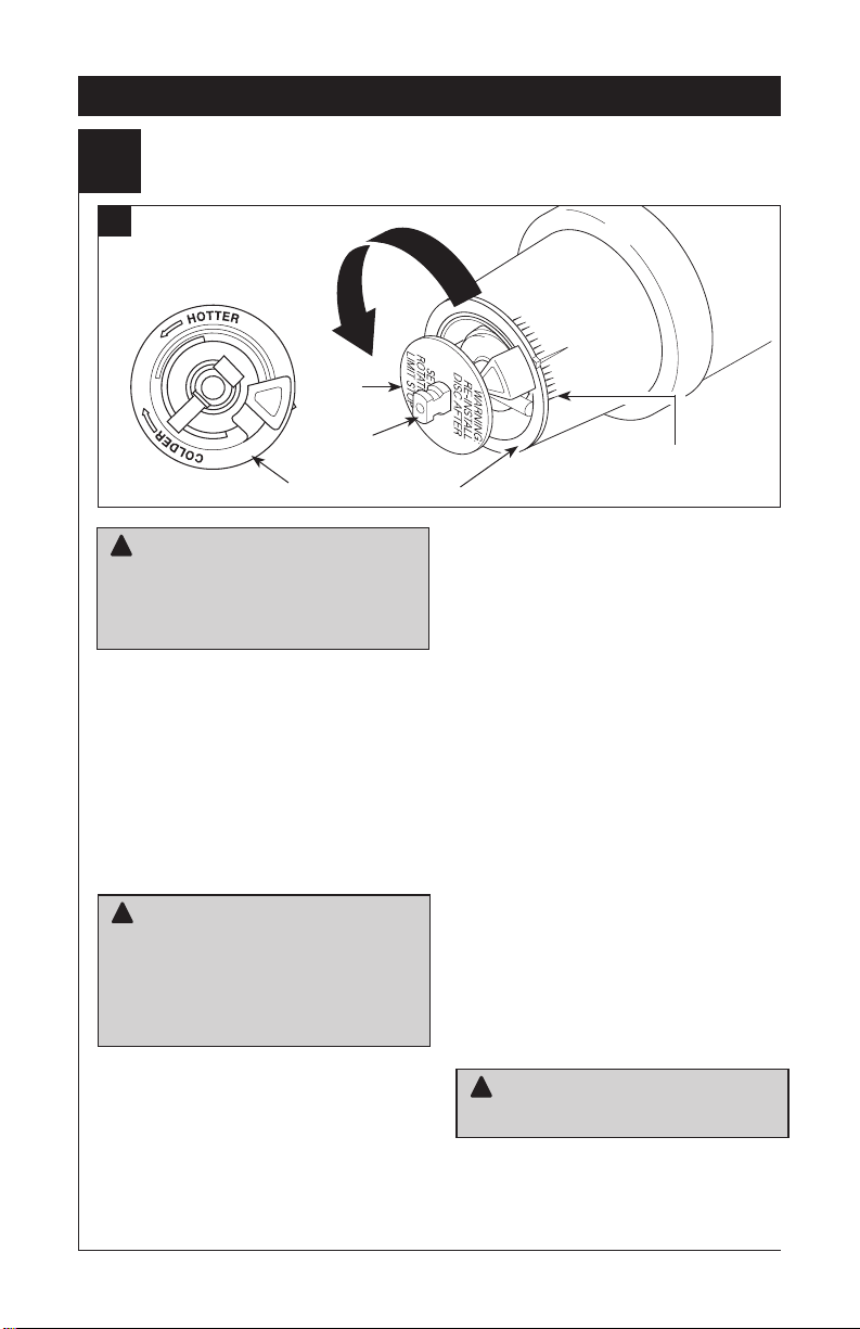
Adjusting the Rotational Limit Stop
4
A.
Hotter
Disc
13 / 14 Series Installation
Stem
Rotational Limit Stop
!
WARNING: The Rotational Limit
Stop is used to limit the amount of hot
water available such that, if set properly,
the user will not be scalded if the handle
accidentally is rotated all the way to “hot”
when a person is showering or filling a tub.
The rst position allows the LEAST amount
of hot water to mix with the cold water in the
system. In the rst position the water will be
the coldest possible when the handle is turned
all the way to hot. As you move the Rotational
Limit Stop counterclockwise, you progressively
add more and more hot water in the mix. The
last position to the left will result in the greatest
amount of hot water to the mix, and the greatest risk of scald injury if someone accidentally
turns the valve handle all the way to the hot
side while showering or lling a tub.
!
WARNING: In some instances, setting
the Rotational Limit Stop in the hottest
position (full counterclockwise) could result
in scald injury. It is necessary to adjust
the Rotational Limit Stop so that the water
coming out of the valve will not scald the
user when the handle of the valve is rotated
to the hot side.
• According to the majority of industry stan-
dards, the maximum allowable temperature of
the water exiting the valve is 120°F (Your local
plumbing codes may require a water tempera-
ture less than 120°F).
• The Rotational Limit Stop may need to be readjusted seasonally if the inlet water tempera-
ture changes. For example, during the winter,
the cold water temperature is colder than it is
72264 Rev. H
1st Position
during the summer which could result in varying outlet temperatures. A water temperature
for a comfortable bath or shower is typically
between 90°F - 110°F.
• Run the water so that the cold water is as
cold as it will get and hot water is as hot as
it will get. Place the handle on the stem (see
page 10, step 5D) and rotate the handle
counterclockwise until the handle stops.
• Place a thermometer in a plastic tumbler
and hold in the water stream. If the water
temperature is above 120°F, the Rotational
Limit Stop must be repositioned clockwise to
decrease valve outlet water temperature to
be less than 120°F or to meet the requirements of your local plumbing codes.
• To adjust the temperature of the water
coming out of the valve, pull the disc back to
a position where it is possible to remove the
Rotational Limit Stop and readjust the teeth
engagement position to the desired temperature. Clockwise will decrease the outlet
temperature, counterclockwise will increase
the outlet temperature. Temperature change
per tooth (notch) could be 4° - 16°F based on
inlet water conditions. Repeat as necessary.
Push disc until fully seated.
!
WARNING: Failure to re-install Disc
after setting Rotational Limit Stop could
result in scald injury.
• Make sure cold water flows from the
valve first. Make sure water flowing from
the valve at the hottest flow possible
does not exceed 120°f or the maximum
allowed by your local plumbing code.
8
Page 9

13 / 14 Series Installation
B.
!
WARNING: The Rotational Limit Stop
is used to limit the amount of hot water
available such that, if set properly, a scald
injury is less likely to occur if the handle
accidentally is rotated all the way to “hot”
when a person is showering or lling a tub.
The rst position allows the LEAST amount
of hot water to mix with the cold water in the
system. In the rst position the water will be
the coldest possible when the handle is turned
all the way to hot. As you move the Rotational
Limit Stop counterclockwise, you progressively
add more and more hot water in the mix.
The last position to the left will result in the
greatest amount of hot water to the mix, and
the greatest risk of scald injury if someone
accidentally turns the valve handle all the way
to the hot side while showering or lling a tub.
!
WARNING: In some instances, setting
the Rotational Limit Stop in the hottest
position (full counterclockwise) could result
in scald injury. It is necessary to adjust
the Rotational Limit Stop so that the water
coming out of the valve will not scald the
user when the handle of the valve is rotated
to the hot side.
1
Hotter
temperature for a comfortable bath or shower
is typically between 90°F - 110°F.
• Run the water so that the cold water is as cold
as it will get and hot water is as hot as it will
get. Place the handle on the stem and rotate
the handle coun- terclockwise until the handle
stops.
• Place a thermometer in a plastic tumbler
and hold in the water stream. If the water
temperature is above 120°F, the Rotational
Limit Stop must be repositioned clockwise to
decrease valve outlet water temperature to
less than 120°F or to meet the
your local plumbing codes.
• To adjust the temperature of the water coming
out of the valve, pull the white Rotational
Limit Stop (1) outward and rotate. Clockwise
rotation will decrease the outlet temperature,
counterclockwise rotation will increase the
outlet temperature. Temperature change per
tooth (notch) could be 4° - 16°F based on inlet
water conditions. Repeat as necessary. When
nished, make sure that the Rotational Limit
Stop is fully retracted into the seated position.
!
WARNING: Do not take the Rotational
Limit Stop apart.
Cooler
1
be
requirements of
• According to the majority of industry
standards, the maximum allowable temperature
of the water exiting the valve is 120°F (Your
local plumbing codes may require a water
temperature less than 120°F).
• The Rotational Limit Stop may need to
be re-adjusted seasonally if the inlet water
temperature changes. For example, during the
winter, the cold water temperature is colder
than it is during the summer which could
result in varying outlet temperatures. A water
• Make sure cold water flows from the
valve first. Make sure water flowing from
the valve at the hottest flow possible does
not exceed 120°f or the maximum allowed
by your local plumbing code.
9
72264 Rev. H
Page 10
13 / 14 Series Installation
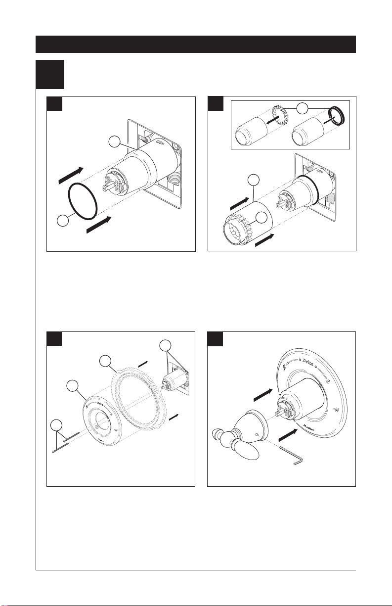
Trim Installation
5
A.
2
1
• Slide O-ring (1) over cartridge and
the bonnet nut (2). The O-ring, which
acts as a spacer to steady the sleeve,
should rest behind the bonnet nut.
C.
2
1
3
B.
2
1
IF YOUR MODEL REQUIRES A
SPACER (1):
• Insert it into the sleeve (2) and push it
to the front.
• Slide the sleeve over the cartridge,
body and O-ring.
1
D.
4
• Secure the escutcheon (1) and backplate
(2) (if your model has one) to the bracket
(3) using the 2 screws provided (4).
• Do not overtighten escutcheon screws.
1072264 Rev. H
• Using an Allen wrench to secure the set
screw, install the handle onto the stem.
Page 11

13/14 Series Maintenance
Faucet leaks from tub spout/showerhead:
SHUT OFF WATER SUPPLIES.
Replace seats and springs–Repair
Kit RP4993. Check condition of lower O-rings and
replace if necessary RP14414. See Helpful Hints
1, 2, & 3.
If leak persists:
SHUT OFF WATER SUPPLIES.
Replace valve cartridge RP46074.
See Helpful Hints 1, 2, 3 & 5.
Unable to maintain constant water temperature:
Replace valve cartridge RP46074 or follow
instructions in Helpful Hints 1, 2, 4 & 5.
Helpful Hints:
1. Before removing valve cartridge assembly for any
maintenance, be sure to note the position of the
rotational limit stop on the cap. The valve cartridge
assembly must always be put back in the same
position. BE SAFE! After you have nished the
installation, turn on valve to make sure COLD
WATER FLOWS FIRST.
2. To remove valve cartridge from body, shut o
water supplies and remove handle and bonnet
nut. Do not pry the valve cartridge out of the body
with a screwdriver. Place handle on stem and rotate
counterclockwise approximately 1/4 turn after the stop
has been contacted. Lift valve cartridge out of body.
Cleaning and Care
Care should be given to the cleaning of this
product. Although its nish is extremely durable, it
can be damaged by harsh abrasives or polish. To
clean, simply wipe gently with a damp cloth and
blot dry with a soft towel.
3. To remove seats and springs, remove valve
cartridge. Separate cap assembly from the
housing assembly by rotating the cap assembly
counterclockwise 90
and housing assemblies. Remove seats and
springs and replace. Place the largest diameter
of the spring into the seat pocket rst and then
press the tapered end of the seal over the spring.
Reassemble valve cartridge and replace in body
following instructions given in 1 above.
4. If the water in your area has lime, rust, sand or
other contaminants in it, your pressure balance
valve will require periodic inspection. The
frequency of the inspection will depend on the
amount of contaminants in the water. To inspect
valve cartridge remove it and follow the steps
in note 1 above. Turn the valve to the full mix
position and shake the cartridge vigorously. If
there is a rattling sound, the unit is functional and
can be reinstalled following instructions given in
note 1 above. If there is no rattle, replace valve
cartridge RP46074.
5. Push disc until fully seated. See pages 8 and 9
for more details.
To order replacement parts, visit
www.deltafaucet.com or call
1-800-345-DELTA (3358)
!
WARNING: Scrubbing Bubbles
Bathroom Cleaner and Lysol
and Tile Cleaner must not be used on the
clear knob handles and levers. Use of these
cleaners can result in cracked or severely
damaged handles. If overspray gets onto
the handles, immediately wipe them dry with
a soft cotton cloth.
o
(degrees). Separate cap
®
®
Basin Tub
11
72264 Rev. H
Page 12
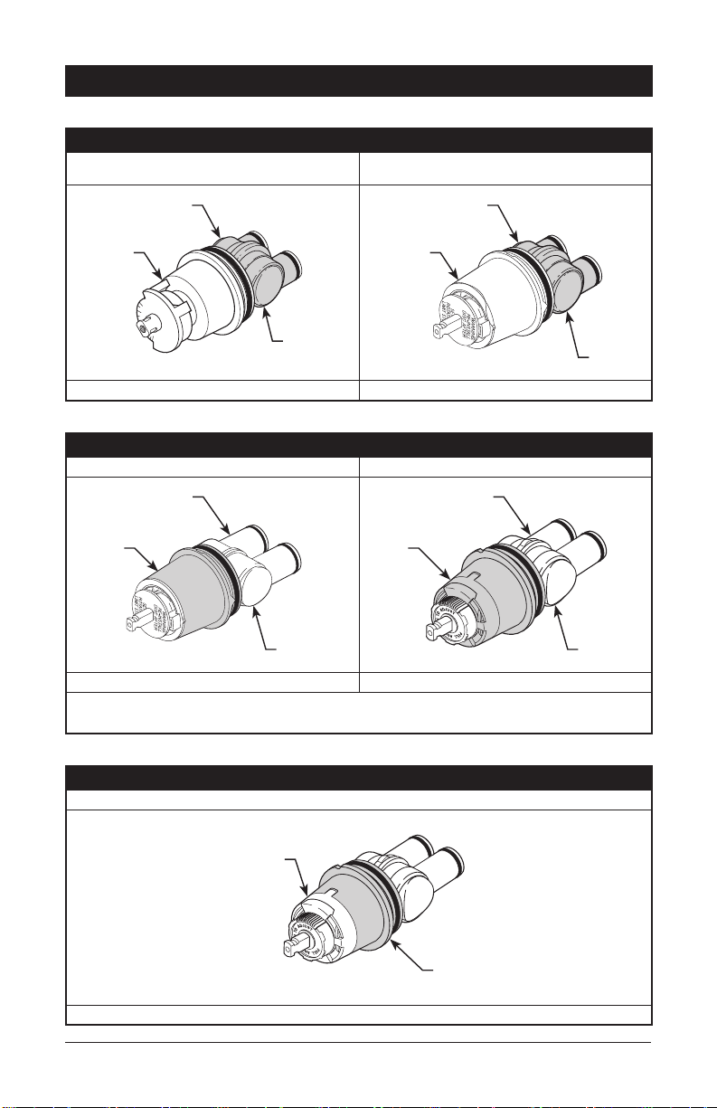
Cartridge Summary Reference Sheet
Monitor® Series 1300/1400
Cartridge shipped before March 2006.
Cartridge shipped in July 2006 and after
(prior to MultiChoice
®
transition).
Shorter lower
housing
White
Blue or
o-white
Order RP19804 to replace cartridge. Order RP19804 to replace cartridge.
Shorter lower
housing
White
Blue
MultiChoice® 13/14
Cartridge shipped from March 2006 to August 2014. Cartridge shipped in August 2014 and after.
Longer lower
housing
Grey
O-white
Order RP46074 to replace cartridge. Order RP46074 to replace cartridge.
Grey
Longer lower
housing
O-white
NOTE: A running change for MultiChoice® 13/14 valves began August 2014, and
features a new Rotational Limit Stop.
72264 Rev. H
®
MultiChoice
Cartridge shipping in select models (-CER).
13/14 (Ceramic)
White
Grey
Order RP74236 to replace cartridge.
12
Page 13

Instrucciones para la
Instalación del Accesorio
para Válvulas MultiChoice
Manual para los
Propietarios
®
13 y 14
Series
Escriba aquí el número del modelo comprado.
Usted puede necesitar
L
O
F
N
E
T
Contenido:
Garantías .......................................................................... Página 2
La instalación de la plomería MultiChoice
Instrucciones de Instalación para la Series 13 / 14 .......... Páginas 6 - 10
Mantenimiento .................................................................. Página 11
Hoja resumen de referencia para el cartucho .................. Página 12
Para ordenar las piezas de repuesto, visítenos en www.deltafaucet.com
!
ADVERTENCIA: El instalador debe
apostar este systema/divisa para garantizar
temperatura maximo y seguro. Cualqueir cambio
en el ajuste puede subir la temperatura del
agua de descarga sobre el límite considerado
seguro y puede resultar en quemaduras de
agua caliente.
AVISO PARA EL INSTALADOR: PRECAUCIÓN
– Como instalador de esta válvula, es su
responsabilidad de INSTALAR Y AJUSTAR
apropiadamente esta válvula como se describe
en las instrucciones, por lo tanto, debe haber
una persona para hacer los ajustes necesarios
del Tope del Límite Rotacional y del pomo
para la temperatura en el momento que se
haga la instalación y pueda necesitar ajustes
adicionales por los cambios estacionales
de la temperatura del agua. USTED DEBE
informarle al dueño/usuario sobre este
requisito siguiendo las instrucciones. Si usted
o el dueño/usuario no están seguros como
hacer estos ajustes apropiadamente, por favor
reérase al Página 8 y 9 y si todavía no está
seguro, llámenos al 1-800-345-DELTA.
Después de hacer la instalación y el ajuste,
usted puede agregarle a la etiqueta de aviso
proporcionada, su nombre, el nombre de la
compañía y la fecha cuando ajustó el Tope del
Límite Rotacional y el pomo para la temperatura
y aplicar o jar la etiqueta al dorso de la puerta
®
...................... Páginas 3 - 5
del gabinete más cercano y la etiqueta de
aviso al calentador de agua. Deje la Hoja de
Instrucciones para referencia del dueño/usuario.
!
ADVERTENCIA: Esta válvula de
presión balanceada y termostática está
diseñada para minimizar los efectos de
los cambios de temperatura de agua por
causa de los cambios de presión en el
agua de entrada, comúnmente causados
por lavadoras de platos, lavadoras de ropa,
inodoros, y otros aparatos por el estilo.
Puede no proporcionar protección de
quemaduras de agua caliente cuando hay
alguna falla de otros aparatos para el control
de temperatura en otro sitio en el sistema
de plomería. También no proporcionará
protección si el tope del límite rotacional y
el pomo para el ajuste de la temperatura
no está apropiadamente fijo o si cambia la
temperatura del agua caliente después de
hacer los ajustes o si los cambios del agua
de entrada son por los cambios estacionales.
No instale un aparato de corte o cierre en
cualquiera de las tomas de esta válvula.
Cuando este tipo de dispositivo interrumpe
el flujo de agua, puede anular la capacidad
de la válvula para equilibrar las presiones
de agua fría y caliente y puede aumentar el
riesgo de lesión debido a quemaduras.
1
06/18/2020 Rev. Hwww.deltafaucet.com
72264
13 y 14 Series13 y 14 Series13 y 14 Series
Page 14

Garantía Limitada en las Llaves de Agua de Delta
Piezas y Acabado. Todas las piezas (excepto los componentes electrónicos y las pilas) y los acabados de los grifos Delta Faucet® comprados de vendedores
autorizados por Delta están garantizados al consumidor comprador original de estar libres de defectos en material y fabricación durante el tiempo que el comprador
original sea propietario de la vivienda en la que el grifo/la llave de agua fue originalmente instalada. En el caso de los consumidores comerciales, (a) el período de
garantía es de diez (10) años para aplicaciones multifamiliares (apartamentos y condominios) y (b) cinco (5) años para todos las otras aplicaciones comerciales,
en cada caso a partir de la fecha de compra. Para los propósitos de esta garantía, el término “aplicación multifamiliar residencial” se refiere a la compra del grifo
de un vendedor autorizado por Delta por el comprador propietario que no vive en la vivienda residencial donde se instaló inicialmente la llave de agua, como en
una unidad alquilada o arrendada, o unidad o vivienda unifamiliar separada (dúplex o casas adosadas), o un condominio, edificio de apartamentos o centro de
vivienda comunitaria. Las siguientes instalaciones no se consideran aplicaciones multifamiliares residenciales, están excluidas de la garantía de 10 años y están
sujetas a la garantía de cinco años: instalaciones industriales, institucionales u otras instalaciones comerciales, como dormitorios, instalaciones de hotelería (hotel,
motel o una alberga para estadías prolongadas), aeropuerto, centro educativo, centro de atención de salud a corto o largo plazo (hospital, centro de rehabilitación,
asilo de ancianos, unidad de vivienda asistida o una unidad residencial de cuidado), espacio público o área común.
Piezas y acabados para grifos recertificados Delta®. Delta Faucet Company ofrece para la venta en deltafaucet.com llaves de agua/grifos recertificados
Delta®. Todas las piezas electrónicas (excepto las partes electrónicas y las pilas) y los acabados de estos grifos recertificados Delta® están garantizados al
consumidor comprador original de estar libres de defectos en material y fabricación durante diez (10) años a partir de la fecha de compra. Para los consumidores
comerciales, el período de garantía es por un (1) año a partir de la fecha de compra.
Piezas electrónicas. Las piezas electrónicas (excepto las pilas), si las hay, de las llaves de agua Delta® compradas de deltafaucet.com o vendedores autorizados
por Delta están garantizadas al consumidor comprador original de estar libres de defectos en material y fabricación durante cinco (5) años a partir de la fecha de
compra o para los consumidores comerciales, por un (1) año a partir de la fecha de compra. No se garantizan las pilas.
Lo que haremos. La compañía Delta Faucet Company reparará o reemplazará, sin costo alguno, durante el período de garantía aplicable (como descrito
arriba) cualquier pieza o acabado que demuestre ser defectuosa en material y/o fabricación bajo la instalación, el uso y el servicio normal. Si la reparación o el
reemplazo no es práctico, Delta Faucet Company puede optar por reembolsarle el precio de compra a cambio de la devolución del producto. Estos son sus
remedios exclusivos.
Lo que no cubre. Debido a que Delta Faucet Company no puede controlar la calidad de los productos Delta vendidos por vendedores no autorizados, a menos
que la ley lo prohíba, esta garantía no cubre los productos Delta comprados a vendedores no autorizados.
No cubre cualquier gasto de labor incurrido por el comprador para reparar, reemplazar, instalar o desmontar este producto. Delta Faucet Company no es respon
sable por cualquier daño al grifo que resulte del desgaste razonable, uso en el exterior, uso indebido, (incluyendo el uso del producto para una aplicación indebida),
agua helada, abuso, negligencia o la instalación, el mantenimiento o la reparación incorrecta, incluido el incumplimiento de las instrucciones de cuidado y limpieza
correspondientes. Delta Faucet Company recomienda el uso de los servicios de un plomero profesional para toda instalación y reparación de los grifos. También
recomendamos que use solo piezas de repuesto genuinas Delta®.
Lo que usted debe hacer para obtener servicio de garantía o piezas de repuesto. Se puede hacer un reclamo de la garantía y se pueden obtener piezas
de repuesto llamando al 1-877-345-DELTA (3358) o contactándonos por correo postal o electrónico como indicado (favor incluya el número del modelo y la
fecha de compra):
En los Estados Unidos y México: En Canadá:
Delta Faucet Company Masco Canada Limited, Plumbing Group
Product Service Technical Service Centre
55 E. 111th Street 350 South Edgeware Road
Indianapolis, IN 46280 St. Thomas, Ontario, Canada N5P 4L1
Attention: Customer Solutions Attention: Customer Service
www.deltafaucet.com/service-parts/contact-us http://www.deltafaucet.ca/customersupport/assistance.html
El comprobante de compra (recibo de venta original) del comprador original debe ser disponible a Delta Faucet Company para todos los reclamos de garantía a
menos que el comprador haya registrado el producto en Delta Faucet Company o es un producto recertificado de Delta® comprado de deltafaucet.com. Esta
garantía aplica solo a las llaves de agua/grifos Delta® fabricados después de enero 1, 2019 e instalados en los Estados Unidos de América, Canadá y México.
La limitación de la duración de las garantías implícitas. Favor tomar nota que algunos estados/provincias (incluyendo Quebec) no permiten las limitaciones
de la duración de una garantía implícita por lo que las limitaciones a continuación puedan no aplicarle. HASTA EL ALCANCE MÁXIMO EN QUE LA LEY LO
PERMITA, CUALQUIER GARANTÍA IMPLÍCITA, INCLUIDAS LAS GARANTÍAS IMPLÍCITAS DE COMERCIABILIDAD Y DE IDONEIDAD PARA UN PROPÓSITO
PARTICULAR, ESTÁ LIMITADA AL PERÍODO LEGAL O A LA DURACIÓN DE ESTA GARANTÍA, LO QUE SEA MÁS CORTO.
Limitación de daños especiales, incidentales o consiguientes. Favor de tomar nota que algunos estados/provincias (incluyendo Quebec) no permiten la
exclusión o limitación de daños especiales, incidentales o consecuentes, por lo que estas limitaciones y exclusiones puedan no aplicarle. HASTA EL ALCANCE
EN QUE LA LEY LO PERMITA, ESTA GARANTÍA NO CUBRE Y DELTA FAUCET COMPANY NO SE HACE RESPONSABLE, POR NINGÚN DAÑO ESPECIAL,
INCIDENTAL O CONSIGUIENTE (INCLUYENDO LOS GASTOS DE LABOR PARA REPARAR, REEMPLAZAR, INSTALAR O DESMONTAR ESTE PRODUCTO),
YA SEA EL RESULTADO DEL INCUMPLIMIENTO DE CUALQUIER GARANTÍA EXPRESA O IMPLÍCITA, INCUMPLIMIENTO DE CONTRATO, AGRAVIO
O DE OTRA MANERA. DELTA FAUCET COMPANY NO SE RESPONSABILIZARÁ POR CUALQUIER DAÑO AL GRIFO QUE RESULTE DEL DESGASTE
RAZONABLE, USO EN EL EXTERIOR DE LA PROPIEDAD, USO INDEBIDO (INCLUYENDO EL USO DEL PRODUCTO PARA UNA APLICACIÓN INDEBIDA),
AGUA HELADA, ABUSO, NEGLIGENCIA O INSTALACIÓN O MANTENIMIENTO INADECUADO O INCORRECTO, INCLUYENDO EL NO SEGUIR LAS
INSTRUCCIONES CORRESPONDIENTES PARA EL CUIDADO, LA LIMPIEZA Y EL MANTENIMIENTO. Aviso para los residentes del estado de New Jersey: Las
disposiciones de este documento tienen la intención de aplicarse en la máxima medida permitida por las leyes del estado de New Jersey.
Derechos adicionales. Esta garantía le otorga derechos legales específicos y también puede tener otros derechos que varían de estado/provincia a estado/
provincia.
Esta es la garantía escrita exclusiva de Delta Faucet Company y la garantía no es transferible.
Si tiene preguntas o dudas con respecto a nuestra garantía, por favor comuníquese con nosotros como se indica anteriormente o consulte nuestras Preguntas
Frecuentes Warranty FAQs en www.deltafaucet.com.
®
© 2020 Delta Faucet Company
-
272264 Rev. H
Page 15

1
Instalación de la plomería MultiChoice®
A.
4
6
1
2
5
CIERRE LOS SUMINISTROS DE AGUA.
Considere el tipo y el grosor de su pared
terminada antes de colocar su placa trasera
de acoplamiento de las tuberías. Instale la
pieza (1) de manera que la superficie de la
pared terminada quede al ras con el frente
del protector de yeso (2) ± 3/8". Nota: Para
con los modelos de las paradas (3), el
protector del yeso debe ser el rubor
B.
3
4
rasante o secundario el 3/8”a la pared
acabada. Instale la pieza usando los dos
agujeros de instalación del acoplamiento
(4) en el soporte. Nota: Quite la cubierta
(5) para tener acceso a los agujeros
de instalación. Cuando esté haciendo la
instalación, asegúrese que la palabra
“UP” (6) quede arriba de la válvula.
2
1
La distancia (1) del empalme de tuberías
(2) al frente del protector de yeso es 2.8"
(71 mm). La distancia (3) del empalme de
tuberías (2) al frente de la tuerca tapa o
capuchón es 3.9" (99 mm).
3
Si usted está trabajando en una pared
delgada, asegúrese de tener un protector
de yeso detrás de la pared, si no la pared
siempre deberá estar al ras con el frente
del protector de yeso.
3 72264 Rev. H
Page 16

Instalación de la plomería MultiChoice®
C.
2
2
2
1
Tubería de
Cobre
Conecte el cuerpo de la válvula a los suministros de agua usando los accesorios apropiados para el tipo de su válvula (tubería de
cobre, hierro o Pex). Nota: (1) es la entrada
del agua fría y el (2) es la entrada del agua
caliente. Si no va a usar alguna de las dos
entradas de agua, séllela con un tapón
de tubería.
D.
1
1
Hierro
Pex
Si está hacienda una instalación dorso
con dorso o a la inversa (caliente en la
derecha y fría en la izquierda) instale el
cuerpo de la válvula como se describe
arriba, pero coloque al inverso las líneas
de suministro de agua. Nota: (1) es
la entrada de agua caliente (2) es la
entrada del agua fría.
1
Quite el capuchón (1).
AVISO: Evite soldar a altas temperaturas. Los
componentes de las tuberías detrás de las
paredes podrían dañarse.
2
Sea seguro que las válvulas apagadas
(2) están quitadas de la versión con las
paradas antes de soldar. (no instale las
válvulas apagadas antes de soldar.)
472264 Rev. H
Page 17

E.
F.
Instalación de la plomería MultiChoice
Conecte la salida de arriba (1) a la tubería de
la regadera con los accesorios apropiados.
Conecte la salida de abajo (2) a la tubería
del surtidor de la bañera con los accesorios
apropiados. La tubería (3) entre el cuerpo de
la válvula y el de la bañera debe ser de un
mínimo de 1/2" (13 mm) de tubería de cobre
ó 1/2" (13 mm) de tubería de hierro en caída
1
2
3
recta no menos de 8" (203 mm) pero no más
de 18" (457 mm) de largo a la entrerrosca del
surtidor de la bañera y con sólo un codo de 90
grados, de tubería de hierro o cobre. No use la
tubería PEX como tubería entre la válvula y
el surtidor de la bañera.
®
1
2
PRUEBA DE PRESIÓN Y
LIMPIEZA DE LA INSTALACIÓN
• Para enjuagar el sistema de desechos,
retire la cubierta y la tuerca tapa.
• Prepare el área para rociar con agua.
• Lentamente abra los suministros de
agua para depurar el sistema por 30
segundos.
• Después de enjuagar, instale el
cartucho y la tuerca tapa.
• Gire la espiga del cartucho en sentido
antihorario hasta que pare.
1
4
2
PARA LOS MODELOS CON TOPES, instale los topes, pero
déjelos en posición completamente abierta. Instale los topes de la
siguiente manera:
• Enrosque la tuerca (3) en la espiga (4) como se muestra. A
continuación, presione el ensamble de la espiga y la tuerca en
la unidad y apriételo con una herramienta de tubo largo con
entrada de 6 puntos de 3/8”. Con un destornillador de cabeza
plana, ajuste la espiga en el sentido de las agujas del reloj para
cerrarla y en el sentido contrario a las agujas del reloj para
abrirla.
• Tape el surtidor de la bañera y/o la salida o salidas de agua de
la regadera con el accesorio apropiado para su tubería.
• Examine si hay fugas.
• Después de hacer la prueba de fugas o filtraciones de agua,
cierre la válvula girando la espiga del cartucho completamente
en el sentido de las agujas del reloj.
5
3
3
4
72264 Rev. H
Page 18

Instalación de las Series 13 / 14
Instalación del Cartucho
2
A.
1
Cierre los suministros de agua. Retire
la cubierta (1) y la tuerca tapa (2) del
cuerpo, si es necesario. Si no es una instalación en pared delgada, puede quitar
el protector de yeso (3) completo.
Instalación de Espalda a Espalda
Instalación Normal (No serequerá cambios)
3
2
B.
2
4
1
Gire el cartucho (1) de manera que las palabras
‘hot side’ (lado caliente) (2) aparezcan a la
izquierda. Introduzca el cartucho en la válvula
como se muestra. Asegúrese que los tubos del
cartucho y los aros-O (3) estén apropiadamente
sentados en los agujeros en la base del cuerpo
de la válvula. Asegúrese que la parte dentada en
el cuerpo de la pieza encaje completamente en
las muescas de éste (4).
3
4
C.
Instalación
Invertido
Fría
Caliente
En las instalaciones dorso con dorso o al
reverso (caliente en la derecha y fría en
la izquierda) introduzca el cartucho con la
inscripción “hot side” a la derecha.
1
Deslice la tuerca tapa (1) sobre el cartucho
y enrosque en el cuerpo de la válvula.
Apriete a mano bien.
672264 Rev. H
Page 19

Instalación de las Series 13 / 14
Instalación de la Cabeza de la Regadera y el Surtidor de la Bañera
3
PARA LAS INSTALACIONES DE LAS CABEZAS
A.
3
2
4
B.
-I- Modelos
2
1
PARA LA INSTALACIÓN DEL SURTIDOR DE LA BAÑERA: Reérase a las instrucciones
para la instalación suministradas con su surtidor. No conecte los surtidores para las
instalaciones en las supercies horizontales en las válvulas dentro de las paredes. No use
las regaderas de mano en vez de un surtidor de bañera conectado a una válvula de bañera/
regadera. No use la tubería PEX como tubería entre la válvula y el surtidor de la bañera.
2
B-1
B-2
B-3
1
DE REGADERA: Conecte la toma de salida de
agua superior (1) al brazo de la regadera (2) con los
accesorios apropiados. Para prevenir daño al acabado
del brazo de la regadera, introduzca el extremo que
va hacia la pared del brazo de la regadera dentro del
reborde (3) antes de atornillar el brazo en la conexión
de la tubería vertical. Aplique cinta para plomero los
enrosques de la tubería. No apriete demasiado la
cabeza de la regadera (4).
-I- MODELOS: Para
combinar las dos
regaderas, inserte
4
la lengüeta superior
(1) en la regadera de
mano en la muesca
(2) de la cabeza de
la regadera. Oprima
3
la regadera de mano
en la cabeza de la
regadera hasta que las
dos partes encajen y
queden juntas.
Instalación deslizable
El tubo de cobre (1) debe ser de1/2” de cobre nominal.
Importante: Si es necesario cortar el tubo de cobre, el
extremo debe biselarse que quede libre de rebabas para
1
1
prevenir cortar o mellar el aro O dentro del tubo de cobre.
Deslice el surtidor sobre el tubo de cobre al ras con la
bañera o la supercie de la pared acabada. Apriete el
tornillo de ajuste (2), pero no apriete demasiado.
Instalación de la tubería de Hierro
IInstale una entrerrosca de tubo enroscado de 1/2”
(13 mm) (1) para extenderse por delante de la pared
acabada. Aplique cinta para plomero las roscas en la
entrerrosca de tubo y atornille el surtidor de la bañera.
Instalación de Soldadura de Cobre
Quite el aro O (1) del adaptador (2). Suelde el adaptador
al tubo asegurando de mantener la soldadura lejos de
1
23
las muesca del aro O. AVISO: No se permite soldadura
en el diámetro exterior del adaptador adyacente a la
ranura de la junta tórica. La soldadura en la ranura o en
el diámetro exterior puede provocar la fuga de agua entre
el adaptador y el surtidor y hacia la cavidad de la pared.
Corte el tubo (3) y coloque otra vez el aro O en la muesca
del adaptador de latón. Atornille la bañera/surtidor al
adaptador, asegurando no dañar el aro O, y apriete a
mano bien hasta que el surtidor quede rmemente contra
la pared acabada y no quede ojo detrás de la pared.
7 72264 Rev. H
Page 20

Instalación de las Series 13 / 14
El Ajuste del Tope que Limita la Rotación
4
A.
Más
Caliente
Disco
Unidad
del Vástago
Tope de Limite de Girar
ADVERTENCIA:
El Ajuste del Tope que Limita la Rotación
se usa para limitar la cantidad de agua
caliente disponible de manera que, si
ajustado apropiadamente, el usuario no se
quemará si la manija se gira accidentalmente
completamente a “hot” (“caliente”) cuando
una persona se está duchando o llenando
la bañera. La primera posición permite la
cantidad MÍNIMA de agua caliente mixta con
la fría en el sistema. En la primera posición
el agua estará lo más fría posible cuando
la manija se gira completamente a caliente.
Mientras que mueve el Ajuste del Tope que
Limita la Rotación en dirección contrario a
las manecillas del reloj, progresivamente
aumentará el agua caliente en la mezcla más
y más. La última posición a la izquierda es
la de mayor cantidad de agua caliente en
la mezcla, y tiene el mayor riesgo de lesión
por quemadura si alguien accidentalmente
abre la manija de la válvula completamente
a la posición caliente mientras que se baña o
llena la bañera.
ADVERTENCIA: En algunos casos,
ajustar el Ajuste del Tope que Limita la
Rotación en la posición más caliente
(completamente en el sentido contrario
a la dirección de las manecillas del reloj)
puede resultar en lesión por quemadura.
Es necesario ajustar el Tope que Limita
la Rotación de manera que el agua que
sale de la válvula no queme o escalde al
usuario cuando la manija de la válvula se
gira al lado caliente.
De acuerdo con la mayoría de los estándares
de la industria, la temperatura máxima
permisible del agua que sale es 120°F (Sus
códigos locales de plomería pueden requerir
una temperatura de agua menor de 120°F).
El Tope que Limita la Rotación puede
requerir el ajuste estacional si la temperatura
del agua cambia. Por ejemplo, durante el
872264 Rev. H
Posición Primera
invierno, la temperatura del agua fría es más
fría que durante el verano resultando en temperaturas variadas en el agua de salida. Una
temperatura de agua para un baño o ducha
confortable típicamente es entre 90°F - 110°F.
Deje que el agua corra de manera que el agua
fría esté lo más fría posible y la caliente esté
lo más caliente posible. Coloque la manija en
la espiga (vea la página 10, paso 5D) y gire la
manija en dirección contraria a las manecillas
del reloj hasta que la manija pare.
Coloque el termómetro en un vaso plástico y
sosténgalo bajo el chorro de agua. Si la tem-
peratura de agua está por encima de 120°F el
tope que limita la rotación debe ajustarse otra
vez moviéndolo en sentido de las manecillas
del reloj para reducir la temperatura del agua
de salida de la válvula a menos de 120°F o
para que cumpla con los requisitos de sus
códigos locales de plomería.
Para ajustar la temperatura del agua que
sale de la válvula, hale el disco otra vez a la
posición donde se puede remover el Tope
del Límite Rotacional y reajuste el engranaje
de los dientes a la posición para la temperatura deseada. Al mover en dirección de las
manecillas del reloj reducirá la temperatura
del agua de salida, y al contrario aumentará la
temperatura del agua de salida. El cambio de
temperatura por cada diente (muesca) puede
ser de 4°F-16°F dependiendo de la condición
del agua de entrada. Si es necesario repítalo.
Presione el disco hasta que está asentado
completamente. ADVERTENCIA: Si no rein-
stala el Disco después de hacer el ajuste
del Tope del Límite Rotacional pudiera
escaldarse con agua demasiado caliente.
ASEGÚRESE QUE EL AGUA FRÍA FLUYA DE
LA VÁLVULA PRIMERO. ASEGÚRESE QUE
EL AGUA QUE FLUYE DE LA VÁLVULA EN LA
POSICIÓN MÁS CALIENTE POSIBLE NO EX-
CEDA 120°F O EL MÁXIMO PERMITIDO POR
SUS CÓDIGOS LOCALES DE PLOMERÍA.
Page 21

Instalación de las Series 13 / 14
B.
ADVERTENCIA:
El Ajuste del Tope que Limita la Rotación se
usa para limitar la cantidad de agua caliente
disponible de manera que, si ajustado
apropiadamente, Una lesión de escaldado es
menos probable que se ocurra si la manija
se gira accidentalmente completamente a
“hot” (“caliente”) cuando una persona se está
duchando o llenando la bañera. La primera
posición permite la cantidad MÍNIMA de
agua caliente mixta con la fría en el sistema.
En la primera posición el agua estará lo
más fría posible cuando la manija se gira
completamente a caliente. Mientras que mueve
el Ajuste del Tope que Limita la Rotación en
dirección contrario a las manecillas del reloj,
progresivamente aumentará el agua caliente
en la mezcla más y más. La última posición a
la izquierda es la de mayor cantidad de agua
caliente en la mezcla, y tiene el mayor riesgo de
lesión por quemadura si alguien accidentalmente
abre la manija de la válvula completamente a la
posición caliente mientras que se baña o llena la
bañera.
• ADVERTENCIA: En algunos casos, ajustar
el Ajuste del Tope que Limita la Rotación en
la posición más caliente (completamente
en el sentido contrario a la dirección de las
manecillas del reloj) puede resultar en lesión
por quemadura. Es necesario ajustar el Tope
que Limita la Rotación de manera que el agua
que sale de la válvula no queme o escalde al
usuario cuando la manija de la válvula se gira
al lado caliente.
• De acuerdo con la mayoría de los estándares
de la industria, la temperatura máxima permisible
del agua que sale es 120°F (Sus códigos locales
de plomería pueden requerir una temperatura de
agua menor de 120°F).
• El Tope que Limita la Rotación puede requerir
el ajuste estacional si la temperatura del agua
cambia. Por ejemplo, durante el invierno, la
1
Hotter
temperatura del agua fría es más fría que
durante el verano resultando en tem-peraturas
variadas en el agua de salida. Una temperatura
de agua para un baño o ducha confortable
típicamente es entre 90°F - 110°F.
• Deje que el agua corra de manera que el
agua fría esté lo más fría posible y la caliente
esté lo más caliente posible. Coloque la manija
en la espiga y gire la manija en dirección
contraria a las manecillas del reloj hasta que la
manija pare.
• Coloque el termómetro en un vaso plástico y
sosténgalo bajo el chorro de agua. Si la tem-
peratura de agua está por encima de 120°F el
tope que limita la rotación debe ajustarse otra
vez moviéndolo en sentido de las manecillas
del reloj para reducir la temperatura del agua de
salida de la válvula a menos de 120°F o para
que cumpla con los requisitos de sus códigos
locales de plomería.
• Para ajustar la temperatura del agua que sale
de la válvula, Tirar la Parada de Límite Rotacional
de color blanco hacia afuera y girarla. Al mover
en dirección de las manecillas del reloj reducirá
la temperatura del agua de salida, y al contrario
aumentará la temperatura del agua de salida. El
cambio de temperatura por cada diente (muesca)
puede ser de 4°F-16°F dependiendo de la
condición del agua de entrada. Si es necesario
repítalo. Cuando haya terminado, asegúrese
de que la Parada de Límite Rotacional esté
completamente retraída a la posición sentada.
ADVERTENCIA: No tome la Parada de Límite
Rotacional aparte.
• ASEGÚRESE QUE EL AGUA FRÍA FLUYA DE
LA VÁLVULA PRIMERO. ASEGÚRESE QUE
EL AGUA QUE FLUYE DE LA VÁLVULA EN
LA POSICIÓN MÁS CALIENTE POSIBLE NO
EXCEDA 120°F O EL MÁXIMO PERMITIDO
POR SUS CÓDIGOS LOCALES DE
PLOMERÍA.
Cooler
1
9 72264 Rev. H
Page 22

Instalación de las Series 13 / 14
Instalación Final
5
A.
2
1
Deslice el aro O (1) sobre el cartucho y la
tuerca tapa (2). El aro O, el cual funciona
como un separador para estabilizar la manga,
debe quedar apoyado en la tuerca tapa.
C.
2
1
3
B.
2
1
Si su modelo requiere un separador (1),
insértelo en la manga (2) y empújelo hacia el
frente. Deslice la manga sobre el cartucho,
el cuerpo de la pieza y el aro O.
1
D.
4
Fije la roseta con oricio (1) y la placa de
atrás (2) (si su modelo tiene una) al soporte
(3) usando los 2 tornillos suministrados
(4). No apriete demasiado los tornillos de la
roseta.
Instale la manija en la espiga, usando una
llave Allen para jar el tornillo de ajuste.
1072264 Rev. H
Page 23

Mantenimiento de las Series 13 / 14
La llave tiene fugas de agua en la
salida de tina/cabeza deregadera–
CIERRE LOS SUMINISTROS DE AGUA.
Reemplace Asientos y Resortes–Equipo de
Reparaciones RP4993 Verica el condición de los
anillos “O” más bajo y repongalos si será necesario
RP14414. Vea Sugerencias Utiles 1, 2, y 3.
Si la fuga de agua persiste–
CIERRE LOS SUMINISTROS DE AGUA.
Reemplace la válvula de cartucho RP46074.
Vea Sugerencia Utiles 1, 2, 3 y 5.
No se puede mantener temperatura de
agua constante:
Reemplace la válvula de cartucho RP46074 o sigue
los instrucciones en Sugerencias Utiles 1, 2, 4 y 5.
Sugerencia Utiles:
1. Antes de remover el ensamble del cartucho de
la válvula para hacerle cualquier servicio, fíjese en
la posición del tope del límite rotacional ubicado en
la tapa. Siempre se debe reponer el ensamble de
cartucho de válvula en el mismo posición. TENGA
CUIDADO después de cumplir el instalación dele
vuelta a la válvula para asegurar que AGUA FRIA
SALGA PRIMERO.
2. Para quitar el cartucho de válvula del cuerpo, cierre
los suministros de agua y quite el maneral y bonete.
No se debe quitar el cartucho de válvula del cuerpo
con atornillador. Ponga el maneral encima el vástago
y giralo en el sentido contrario al de las agujas del
reloj aproximado 1/4 vuelta. Levanta el cartucho de
válvula aguera el cuerpo.
3. Para quitar los asientos y resortes, quite el
cartucho de válvula, (vea arriba). Separa ensamble
de botón de ensamble de caja girando el botón
90o en el sentido contrario al de las agujas del
reloj. Separa ensambles de botón y caja. Quite los
asientos y resortes y ponga los asientos y resortes
nuevos. Ponga primero el diámetro mas grande del
resorte adentro la bolsa del asiento y luego apreta
el remate ahusado del sello hacia arriba el resorte.
Reensembla el cartucho de válvula y repongalo en el
cuerpo siguendo los instrucciones en nota 1 arriba.
4. Si la agua en su area contiene cal, orín, arena
o otros contaminamientos, su válvula de equilibrio
de presión requerá inspecciones periódico. La
frequencía de los inspecciones depende en el tamaño
de contaminamientos en la agua. Para inspectar el
cartucho, quite el cartucho, sigue los pasos apuntado
en nota 1 arriba. Dele vuelta al válvula hasta el
posición completamente mixto y sacude el cartucho
riguroso. Si hay traqueteo, funciona el unidad y se
puede reinstalar siguendo nota 1 de arriba. Si no
hay traqueteo, reemplace la válvula de cartucho
RP46074.
5. Presione el disco hasta que está asentado
completamente. Vea la páginas 8 y 9 para más
detalles.
Para ordenar las piezas de repuesto, visítenos
en www.deltafaucet.com o llámenos al
1-800-345-DELTA (3358)
Limpieza y Cuidado de su Llave
Tenga cuidado al ir a limpiar este producto.
Aunque su acabado es sumamente durable,
puede ser afectado por agentes de limpieza o
para pulir abrasivos. Para limpiar su llave, simplemente frótela con un trapo húmedo y luego
séquela con una toalla suave.
¡ADVERTENCIA! No se puede usar
SCRUBBING BUBBLES® BATHROOM
CLEANER o LYSOL® BASIN TUB AND TILE
CLEANER en las manijas transparentes. El
uso de estos productos pueden resultar en manijas rajados o severamente dañados. Si estos productos caen sobre la manija, séquelo inmediatamente con una toalla de algodón suave.
11 72264 Rev. H
Page 24

Hoja resumen de referencia para el cartucho
Monitor® Series 1300/1400
El cartucho enviado antes de marzo 2006.
El cartucho enviado en julio 2006 y después
(antes de la transición a MultiChoice
®
).
Más corto Más
abajo Bastidor
Blanco
Azul o
Blancuzco
Ordene el Repuesto RP19804 para cambiar el
cartucho.
Más corto Más
abajo Bastidor
Blanco
Azul
Ordene el Repuesto RP19804 para cambiar el
cartucho.
MultiChoice® 13/14
El cartucho enviado entre marzo 2006 y agosto 2014. El cartucho enviado en agosto 2014 y después.
Bastidor más Largo
Ubicado más Abajo
Gris
Blancuzco
Ordene el Repuesto RP46074 para cambiar el
cartucho.
Bastidor más Largo
Ubicado más Abajo
Gris
Blancuzco
Ordene el Repuesto RP46074 para cambiar el
cartucho.
NOTA: Un cambio vigente de las válvulas Multichoice® 13/14 comenzó en agosto
2014, y cuenta con un nuevo límite de parada rotacional.
72264 Rev. H
®
MultiChoice
Cartuchos enviados en algunos de modelos (-CER).
13/14 (Cerámico)
Blanco
Gris
Ordene el Repuesto RP74236 para cambiar el cartucho.
12
Page 25

Instructions d’installation
Finition de la soupape
MultiChoice
®
Guide d’utilisation
13 et 14
Séries
Inscrivez le numéro de modèle ici.
Articles dont vous pouvez avoir besoin:
L
O
F
N
E
T
Table des matières
Garanties ............................................................................. Page 2
Installation de la plomberie brute MultiChoice
Instructions d’installation - Séries 13 et 14 .......................... Pages 6 - 10
Maintenance ........................................................................ Page 11
Fiche de référence sommaire de la cartouche .................... Page 12
Pour commander des pièces de rechange, visitez www.deltafaucet.com
®
................... Pages 3 - 5
72264
13 et 14 Series13 et 14 Series13 et 14 Series
MISE EN GARDE : L’installateur doit régler
l’appareil pour que la température maximale de
l’eau chaude soit sans danger. Toute modication
des réglage peut entraîner une élévation de la
température à la sorite du robinet au delà de la
température sans danger et pourrait causer un
échaudage.
AVIS À L’INSTALLATEUR : ATTENTION! – En
qualité d’installateur, vous êtes tenu
d’INSTALLER et de RÉGLER ce robinet
conformément aux instructions. Ce robinet ne
s’adapte pas automatiquement aux uctuations
de la température de l’eau d’alimentation. Par
conséquent, il faut régler la butée limitatrice de
température ou le bouton de température au
moment de l’installation et il peut être
nécessaire de faire de nouveaux réglages par
la suite en raison des uctuations saisonnières
de la température de l’eau. VOUS DEVEZ
informer le propriétaire ou l’utilisateur de cette
exigence. En cas de doute quant à la marche à
suivre pour faire ces réglages, veuillez
consulter vs 8 et 9 si un doute persiste, et si
cette incertitude persiste, appelez-nous au
1-800-345-DELTA.
Après avoir terminé l’installation et le réglage, vous
devez inscrire, sur l’étiquette de mise en garde
fournie, votre nom, le nom de votre entreprise et la
date à laquelle vous avez réglé la butée limitatrice
de température ou le bouton de température, puis
xer l’étiquette à l’endos de la porte de la coieuse.
Vous devez également xer l’étiquette
www.deltafaucet.com
d’avertissement au chaue-eau. Veuillez laisser
ce feuillet d’instructions au propriétaire ou à
l’utilisateur pour qu’il puisse le consulter
au besoin.
MISE EN GARDE – Ce robinet thermostatique
à équilibrage de pression pour baignoire est
conçu pour limiter les eets des uctuations
de température de l’eau causées par les
variations de la pression d’alimentation
attribuables au fonctionnement d’un
lave-vaisselle, d’une machine à laver, d’un
cabinet d’aisances ou d’un autre appareil
qui consomme de l’eau. Il peut ne pas
protéger l’utilisateur contre l’échaudage en
cas de défectuosité d’un autre dispositif de
régulation de la température, si le réglage de
la butée limitatrice de haute température ou
du bouton de température est mauvais, si la
température de l’eau chaude a été modiée
après que les réglages ont été eectués ou
si la température de l’eau d’alimentation a
changé en raison du changement de saison.
N’installez pas de dispositif d’arrêt sur
une sortie quelconque de ce robinet.
En interrompant l’écoulement de l’eau,
ce dispositif peut empêcher le robinet
d’équilibrer les pressions d’eau chaude et
d’eau froide et d’eau froide et accroître les
risques de brûlure.
1
06/18/2020 Rev. H
Page 26

Garantie limitée des robinets Delta
Pièces et finis. Tous les pièces (autres que les composants électroniques et les piles) et les finis de ce robinet Delta® achetés chez des vendeurs Delta autorisés
sont protégés contre les défectuosités du matériau et les vices de fabrication par une garantie qui est consentie au premier acheteur au détail et qui demeure
valide tant que celui-ci demeure propriétaire de la maison dans laquelle le robinet a été installé. En ce qui concerne les acheteurs commerciaux, la période de
garantie est a) de dix (10) ans pour les applications résidentielles multifamiliales et b) de cinq (5) ans pour toutes les autres applications commerciales, à compter
de la date d’achat dans chaque cas. Dans le libellé de la présente garantie, on entend par « application résidentielle multifamiliale », un robinet acheté chez un
vendeur Delta autorisé par un acheteur qui est propriétaire d’un logement résidentiel sans l’habiter et installé la première fois dans cet immeuble. Il peut s’agir
d’un immeuble individuel comportant un ou plus d’un logement loué (duplex ou groupe de maisons en rangée), d’un condominium, d’un immeuble d’habitation
ou d’un centre d’intégration communautaire. Les applications décrites ci-après ne sont pas considérées comme des applications multifamiliales et elles sont
couvertes par la garantie de cinq (5) ans plutôt que par la garantie de dix (10) ans. Ce sont les suivantes : robinets installés dans un bâtiment industriel, un
bâtiment institutionnel et un autre immeuble commercial, notamment une résidence d’étudiants, un lieu d’hébergement (hôtel, motel ou lieu de séjour prolongé),
un aéroport, un établissement d’enseignement, un établissement de soins de santé de courte ou de longue durée (hôpital, centre de réadaptation, maison de
soins infirmiers), un endroit public ou un lieu commun.
Pièces et finis pour les robinets recertifiés Delta®. Delta Faucet Company offre en vente sur deltafaucet.com des robinets recertifiés Delta®. Tous les pièces
(autres que les composants électroniques et les piles) et les finis de ces robinets recertifiés Delta® sont protégés contre les défectuosités de matériau et les vices
de fabrication par une garantie d’une durée de dix (10) ans qui est consentie au premier acheteur au détail à compter de la date d’achat par ledit acheteur. En ce
qui concerne les acheteurs commerciaux, la durée de la garantie est d’un (1) an à compter de la date d’achat par le premier acheteur.
Composants électroniques. Les composants électroniques (autres que les piles) de ce robinet Delta® qui ont été achetés chez des vendeurs Delta autorisés
sont protégés contre les défectuosités du matériau et les vices de fabrication par une garantie consentie au premier acheteur au détail qui est de cinq (5) ans
à compter de la date d’achat. En ce qui concerne les acheteurs commerciaux, la période de garantie est d’un (1) an à compter de la date d’achat. Les piles ne
sont pas couvertes par la garantie.
Ce que nous ferons. Delta Faucet Company réparera ou remplacera gratuitement, pendant la période de garantie applicable (décrite ci-dessus), toute pièce
ou tout fini qui présentera une défectuosité de matériau et/ou un vice de fabrication pour autant que le produit ait été installé, utilisé et entretenu normalement.
S’il n’est pas utile de réparer ou de remplacer le produit, Delta Faucet Company pourra rembourser le prix d’achat en échange du produit retourné. Il s’agit de
vos seuls recours.
Ce qui n’est pas couvert. Étant donné que Delta Faucet Company n’est pas en mesure de contrôler la qualité des produits vendus par des vendeurs non auto
risés, la présente garantie ne s’applique pas aux produits Delta vendus par des vendeurs non autorisés, à moins que cette restriction ne soit interdite par la loi.
La présente garantie ne couvre pas les frais de main-d’œuvre encourus par l’acheteur pour la réparation, le remplacement, l’installation ou la dépose du robinet.
Delta Faucet Company se dégage de toute responsabilité à l’égard de toute détérioration du robinet résultant d’une usure raisonnable et des dommages causés
par une utilisation à l’extérieur, un mauvais usage (y compris l’utilisation du produit à des fins autres que celles auxquelles il est destiné), le gel de l’eau, un usage
abusif, la négligence ou l’utilisation d’une méthode d’installation, de maintenance ou de réparation incorrecte ou inadéquate, y compris les dommages résultant
du non-respect des instructions de nettoyage et d’entretien applicables. Delta Faucet Company vous recommande de confier tous les travaux d’installation et de
réparation à un plombier professionnel. Nous vous recommandons également d’utiliser uniquement des pièces de rechange Delta® authentiques.
Ce que vous pouvez faire pour vous prévaloir de la garantie ou obtenir des pièces de rechange.
Vous pouvez présenter une réclamation en vertu de la garantie et obtenir des pièces de rechange en appelant au 1-800-345-DELTA (3358) ou en communiquant
avec nous à l’une des adresses postales ou des adresses de courriel indiquées ci dessous (n’oubliez pas d’indiquer le numéro de modèle et la date d’achat).
Aux États-Unis et au Mexique Au Canada:
Delta Faucet Company Masco Canada Limited, Groupe plomberie
Product Service Centre de services techniques
55 E. 111th Street 350, chemin South Edgeware
Indianapolis, IN 46280 St. Thomas (Ontario) Canada N5P 4L1
Attention: Customer Solutions À l’attention du Service à la clientèle
www.deltafaucet.com/service-parts/contact-us http://www.deltafaucet.ca/customersupport/assistance.html
La preuve d’achat (original du reçu) du premier acheteur doit être présentée à Delta Faucet Company pour toutes les réclamations en vertu de la garantie, sauf si
le produit a été enregistré auprès de Delta Faucet Company ou s’il s’agit d’un produit recertifié Delta® qui a été acheté de deltafaucet.com. La présente garantie
s’applique uniquement aux robinets Delta® fabriqués après le 1er janvier 2019 et installés aux États-Unis d’Amérique, au Canada et au Mexique.
Limitation de la durée des garanties implicites. Veuillez noter que dans les États ou les provinces (y compris le Québec) où il est interdit de limiter la
durée d’une garantie implicite, les limites mentionnées ci-dessous peuvent ne pas s’appliquer. DANS LA MESURE DE CE QUI EST PERMIS PAR LA LOI
APPLICABLE, TOUTES LES GARANTIES IMPLICITES, Y COMPRIS LES GARANTIES IMPLICITES DE QUALITÉ MARCHANDE ET D’ADÉQUATION À UN
USAGE PARTICULIER, SE LIMITENT À LA PÉRIODE FIXÉE PAR LA LOI OU À LA DURÉE DE LA PRÉSENTE GARANTIE, LA PLUS COURTE DES DEUX
PÉRIODES S’APPLIQUANT.
Limitation des dommages particuliers, consécutifs ou indirects. Veuillez noter que dans les États ou les provinces (y compris le Québec) où il est interdit
d’exclure ou de limiter les dommages particuliers, consécutifs ou indirects, les exclusions et les limites mentionnées ci-dessous peuvent ne pas s’appliquer. DANS
LA MESURE DE CE QUI EST PERMIS PAR LA LOI APPLICABLE, DELTA FAUCET COMPANY SE DÉGAGE DE TOUTE RESPONSABILITÉ À L’ÉGARD DES
DOMMAGES PARTICULIERS, CONSÉCUTIFS OU INDIRECTS (Y COMPRIS LES FRAIS DE MAIN-D’ŒUVRE POUR LA RÉPARATION, LE REMPLACEMENT,
L’INSTALLATION OU LA DÉPOSE DU PRODUIT), PEU IMPORTE QU’ILS DÉCOULENT D’UNE RUPTURE D’UNE GARANTIE IMPLICITE OU EXPLICITE,
D’UNE RUPTURE DE CONTRAT, D’UN DÉLIT CIVIL OU D’UNE AUTRE CAUSE. DELTA FAUCET COMPANY SE DÉGAGE DE TOUTE RESPONSABILITÉ À
L’ÉGARD DE TOUTE DÉTÉRIORATION DU ROBINET RÉSULTANT D’UNE USURE RAISONNABLE ET DES DOMMAGES CAUSÉS PAR UNE UTILISATION
À L’EXTÉRIEUR, UN MAUVAIS USAGE (Y COMPRIS L’UTILISATION DU PRODUIT À DES FINS AUTRES QUE CELLES AUXQUELLES IL EST DESTINÉ), LE
GEL DE L’EAU, UN USAGE ABUSIF, LA NÉGLIGENCE OU L’UTILISATION D’UNE MÉTHODE D’INSTALLATION, DE MAINTENANCE OU DE RÉPARATION
INCORRECTE OU INADÉQUATE, Y COMPRIS LES DOMMAGES RÉSULTANT DU NON-RESPECT DES INSTRUCTIONS D’INSTALLATION, D’ENTRETIEN
ET DE NETTOYAGE APPLICABLES, ET CES DOMMAGES NE SONT PAS COUVERTS PAR LA GARANTIE. Avis à l’intention des résidants de l’État du New
Jersey : Les dispositions de la présente garantie, y compris ses limitations, s’appliquent dans toute la mesure permise par les lois de l’État du New Jersey.
Droits supplémentaires. La présente garantie vous procure des droits précis reconnus par la loi. Vous pouvez avoir d’autres droits qui varient selon l’État ou
la province.
La présente garantie écrite est la seule garantie offerte par Delta Faucet Company et elle n’est pas transférable.
Si vous avez des questions ou des préoccupations concernant notre garantie, veuillez communiquer avec nous de la manière indiquée ci-dessus ou consulter
notre FAQ sur la garantie à www.deltafaucet.com.
®
© 2020 Delta Faucet Company
-
272264 Rev. H
Page 27

1
A.
Installation de la plomberie brute MultiChoice
4
6
®
1
2
5
INTERROMPEZ L’ALIMENTATION EN EAU.
Déterminez le type de la paroi et son
épaisseur totale avant de placer la plaque
arrière. Installez le corps (1) de sorte que
la surface finie de la paroi soit à égalité
avec l’avant du protecteur (2) ± 3/8 po.
Note : Pour avec des modèles d’arrêts
(3), la garde de plâtre doit être l’éclat
affleurant ou secondaire 3/8 po au
B.
3
4
mur fini. Installez le corps utilisez les
deux trous (4) de la fixation qui donnent
sur l’entretoise. Note : Enlevez le cou-
vercle (5) pour découvrir les trous de
montage. Au moment de l’installation,
assurez-vous que le mot « UP » (6) sur
le dessus du corps de robinet se trouve
en haut.
2
1
Distance (1) from the stringer (2) to the
front of the plasterguard is 2.8" (71 mm).
Distance (3) from the stringer (2) to the
front of the bonnet is 3.9" (99 mm).
3
If a thin wall is used, be sure to have the
plasterguard behind the wall, otherwise
the wall should always be flush with the
front of the plasterguard. See instruction
on the bag for thin wall mounting.
3 72264 Rev. H
Page 28

Installation de la plomberie brute MultiChoice
C.
2
2
®
2
1
Cuivre Fer
Raccorder le corps de robinet à la tuyauterie
(cuivre, fer ou Pex). Note : (1) correspond
à l’entrée d’eau froide et (2) correspond à
l’entrée d’eau chaude. Si l’une des entrées
est inutilisée, obturez-la avec un bouchon.
D.
1
1
Pex
1
Dans le cas d’une installation dos à dos
ou inversée (eau chaude à droite et eau
froide à gauche), installez le corps de
robinet de la manière indiquée ci-dessus.
La tuyauterie d’alimentation doit toutefois
être inversée. Note : (1) est l’entrée
d’eau chaude et (2) est l’entrée d’eau
froide.
Enlevez le chapeau (1).
Avise : évitez le brasage à haute température.
Le composants du robinet brut pourraient
s’abîmer.
2
Soyez sûr que des valves coupées (2)
sont enlevées de la version avec des
arrêts avant la soudure. (n’installez des
valves coupées avant la soudure.)
472264 Rev. H
Page 29

E.
F.
Installation de la plomberie brute MultiChoice
À l’aide des raccords appropriés, raccordez
l’orifice supérieur (1) au tuyau de la douche
et l’orifice inférieur (2) au tuyau du bec de
baignoire. Le corps de robinet doit être relié au
bec de baignoire par un tuyau de cuivre d’au
moins 1/2 po (13 mm) ou un tuyau de fer d’au
moins 1/2 po (13 mm). Ce tuyau (3) doit être
droit et il doit avoir une longueur d’au moins 8
1
2
3
po (203 mm) et d’au plus 18 po (457 mm); il
doit être relié au tuyau du bec de baignoire par
un seul coude à 90 degrés en cuivre ou en fer.
N’utilisez pas de tube PEX pour raccorder
le bec.
®
1
1
2
ESSAI SOUS PRESSION ET RINÇAGE DE
L’INSTALLATION
• Pour évacuer les corps étrangers de la
robinetterie, enlevez le capuchon et l’écrouchapeau.
• Préparez l’endroit où l’eau giclera.
• Rétablissez l’alimentation en eau lentement et
laissez l’eau s’écouler pendant 30 secondes
pour évacuer les corps étrangers.
• Une fois le rinçage terminé, installez la
cartouche et l’écrou-chapeau.
• Tournez la tige de la cartouche dans le sens
antihoraire jusqu’à ce qu’elle se bloque.
2
POUR LES MODÈLES MUNIS DE POINTEAUX,
installez les pointeaux, mais laissez-les complètement
ouverts. Installez les pointeaux de la manière suivante :
• Vissez l’écrou (3) sur la tige (4) de la manière indiquée
• Bouchez la(les) sortie(s )pour le bec de baignoire et/ou
• Vérifiez l’étanchéité.
• Après avoir vérifié l’étanchéité, fermez la soupape en
3
4
4
3
sur la figure. Enfoncez ensuite la tige avec l’écrou dans
le corps et serrez l’écrou à l’aide d’une douille longue à 6
pans de 3/8 po. À l’aide d’un tournevis à extrémité plate,
tournez la tige dans le sens horaire pour fermer l’arrivée
d’eau et dans le sens antihoraire pour l’ouvrir.
la douche à l’aide des raccords appropriés.
tournant la tige de la cartouche à fond dans le sens
horaire.
5
72264 Rev. H
Page 30

Installation – Séries 13 et 14
Installation de la cartouche
2
A.
1
Interrompez l’arrivée d’eau. Enlevez la
coie (1) et l’écrou-chapeau (2) du corps,
au besoin. Si l’installation n’est pas effectuée sur un mur mince, vous pouvez
enlever le protecteur (3).
3
2
Installation dos à dos
Installation normale (Non modiée)
B.
2
4
1
Tournez la cartouche (1) de sorte que la
mention « hot side » (2) se trouve du côté
gauche. Introduisez la cartouche dans le
corps de la soupape comme le montre la
gure. Assurez-vous que les tubes et les
joints toriques (3) de la cartouche sont bien
calés à la base du corps. Assurez-vous que
les ergots sur le corps sont parfaitement
engagés dans les rainures du corps (4).
3
4
C.
Installation
Inversée
Eau Froides
Eau Chaude
Dans le cas d’une installation dos à dos ou
inversée (eau chaude à droite et eau froide
à gauche), introduisez la cartouche de
sorte que la mention « hot side » se trouve
du côté droit.
1
Faites glisser l’écrou à portée sphérique
(1) sur la cartouche et vissez-le sur le
corps. Serrez à la main fermement.
672264 Rev. H
Page 31

Installation – Séries 13 et 14
Installation de la pomme de douche et du bec de
baignoire
3
INSTALLATION DE LA POMME DE DOUCHE : Rac-
A.
3
2
4
B.
-I- Modèles
2
1
INSTALLATION DU BEC DE BAIGNOIRE : Consultez les instructions d’installation fournies
avec le bec. Ne raccordez pas à une soupape murale à un bec conçu pour être monté sur
une plage. Ne raccordez pas une douche à main à la sortie d’un robinet de baignoire-douche
prévue pour un bec de baignoire. N’utilisez pas de tube PEX pour raccorder le bec.
2
B-1
B-2
B-3
1
cordez la sortie supérieure (1) au tuyau d’alimentation
de la pomme de douche (2) à l’aide des raccords appro-
priés. Pour éviter d’abîmer le ni du tuyau de la pomme
de douche, introduisez le côté « mur » de celui-ci dans
la collerette (3) avant de le visser dans le raccord du
tuyau vertical. Appliquez du ruban de plomberie sur
les lets. Vissez la pomme de douche (4) sur le tuyau.
Appliquez du ruban de plomberie sur les lets. Prenez
garde de serrer la pomme de douche excessivement.
-I- MODÈLES: Pour
combiner les deux
douches, introduisez
4
la patte supérieure (1)
de la douche à main
dans la rainure (2) de
la pomme de douche.
Poussez la douche à
3
Installation d’un bec coulissant
Le tube de cuivre (1) doit avoir un diamètre nominal
de1/2 po. Important : Si vous devez couper le tube de
cuivre, chanfreinez son extrémité de sorte qu’elle ne
risque pas d’endommager le joint torique à l’intérieur
1
1
1
23
du bec. Faites glisser le bec sur le tube de cuivre
de sorte qu’il s’appuie contre la surface nie de la
baignoire ou du mur. Serrez la vis de calage (2), mais
prenez garde de la serrer excessivement.
Installation à l’aide d’un tuyau de fer
Installez le manchon leté (1) 1/2 po (13 mm) de
manière que sa saillie par rapport à la surface nie du
mur. Appliquez du ruban de plomberie sur les lets du
manchon et xez celui-ci au bec de baignoire en vissant.
Installation à l’aide d’un tuyau de cuivre brasé
Retirez le joint torique (1) de l’adaptateur (2). Brasez
l’adaptateur au tube en prenant garde d’échapper du métal d’apport dans la rainure pour le joint torique.
AVIS : IL NE DOIT PAS Y AVOIR DE MÉTAL
D’APPORT SUR LA CIRCONFÉRENCE EXTÉRIEURE
DE L’ADAPTATEUR PRÈS DE LA RAINURE POUR
LE JOINT TORIQUE. Du métal d’apport dans la rainure
ou sur la surface extérieure peut causer une fuite entre
l’adaptateur et le bec, et l’eau peut s’inltrer dans le mur.
Coupez le tube (3) et remettez le joint torique en place
dans la raInure de l’adaptateur en laiton. Vissez le bec
de baignoire sur l’adaptateur et prenant garde d’abîmer
le joint torique. Serrez le bec à la main jusqu’à ce qu’il
s’appuie solidement contre la surface nie de la paroi et
qu’il n’y ait plus de jeu derrière le mur.
main dans la pomme de
douche jusqu’à ce que
les deux éléments se
bloquent ensemble et
deviennent solidaires.
7 72264 Rev. H
Page 32

Installation – Séries 13 et 14
Réglage de la butée anti-échaudage
4
Plus
chaude
Disque
Obturateurs
Butée anti-échaudage
1ère Position
MISE EN GARDE :
La butée antiéchaudage sert à limiter la
quantité d’eau chaude disponible de sorte que
l’utilisateur ne risque pas d’être ébouillanté
si la manette est amenée à l’extrémité
de la plage du côté « Eau chaude » par
inadvertance alors que quelqu’un se trouve
sous la douche ou dans la baignoire. La
première position est celle qui laisse passer
le MOINS d’eau chaude à mélanger avec
l’eau froide. À la première position, l’eau
est aussi froide que possible alors que la
manette se trouve à l’extrémité de la plage
du côté « Eau chaude ». En tournant la butée
antiéchaudage, vous ajoutez progressivement
de plus en plus d’eau chaude au mélange.
La dernière position à gauche est celle qui
laisse passer le plus d’eau chaude et le risque
d’ébouillantage est plus élevé si quelqu’un
amène la manette à l’extrémité de la plage
du côté « Eau chaude » par inadvertance
alors que quelqu’un d’autre se trouve sous la
douche ou dans la baignoire.
MISE EN GARDE : Dans certains cas,
l’ébouillantage est possible si la butée
antiéchaudage se trouve à la position
la plus chaude (à l’extrémité de la plage
dans le sens antihoraire). Il faut régler la
butée antiéchaudage de manière que l’eau
s’écoulant du robinet ne puisse causer de
brûlures à l’usager alors que la manette est
à la position « Eau chaude ».
• Selon la plupart des normes en vigueur dans
l’industrie, la température de l’eau à la sortie du
robinet ne doit pas dépasser 120 °F (certains
codes de plomberie peuvent prescrire une
température inférieure à cette valeur).
• La butée antiéchaudage peut devoir être
réglée à chaque saison si la température de
l’eau d’alimentation change. Par exemple, la
température de l’eau froide est plus basse
en hiver qu’en été, ce qui peut entraîner une
variation de la température à la sortie du
robinet. La température idéale pour la douche
ou le bain se situe généralement entre
90 °F - 110 °F.
• Faites couler l’eau de sorte qu’elle soit aussi
froide que possible et aussi chaude que
possible. Placez ensuite la manette sur la
tige (reportez-vous à la page 10, étape 5D) et
tournez la manette dans le sens antihoraire
jusqu’à l’extrémité de la plage.
• Placez un thermomètre dans un gobelet en
plastique et mettez celui-ci sous le jet d’eau.
Si la température de l’eau est supérieure à
120°F, tournez la butée antiéchaudage dans
le sens horaire pour abaisser la température
de l’eau à la sortie du robinet sous 120°F
ou à une valeur conforme aux exigences du
code de plomberie de votre région.
• Pour régler la température de l’eau qui
s’écoule de la soupape, amenez le disque
dans une position où il est possible d’enlever
la butée de température et engagez les
dents dans les encoches qui correspondent
à la température désirée. La température
diminue dans le sens horaire et augmente
dans le sens antihoraire. La variation de
température est de 4 à 16 °F par cran,
selon la température de l’eau d’alimentation.
Refaites le réglage au besoin. Remettez le
disque jusqu’à ce qu’entièrement assis.
MISE EN GARDE : Il y a risque
d’ébouillantage si on omet de réinstaller
le disque après avoir réglé la butée de
température.
• ASSUREZ-VOUS QUE L’EAU FROIDE
S’ÉCOULE DE LA SOUPAPE EN PREMIER.
ASSUREZ-VOUS QUE LA TEMPÉRATURE
DE L’EAU NE PEUT DÉPASSER 120 °F OU
LA VALEUR MAXIMALE AUTORISÉE PAR LE
CODE DE PLOMBERIE DE VOTRE RÉGION.
872264 Rev. H
Page 33

Installation – Séries 13 et 14
B.
IMPORTANT:
La butée antiéchaudage sert à limiter la
quantité d’eau chaude disponible de sorte Une
blessure par échaudage est moins susceptible
de se produire. si la manette est amenée à
l’extrémité de la plage du côté « Eau chaude
» par inadvertance alors que quelqu’un se
trouve sous la douche ou dans la baignoire. La
première position est celle qui laisse passer le
MOINS d’eau chaude à mélanger avec l’eau
froide. À la première position, l’eau est aussi
froide que possible alors que la manette se
trouve à l’extrémité de la plage du côté « Eau
chaude ». En tournant la butée antiéchaudage,
vous ajoutez progressivement de plus en plus
d’eau chaude au mélange. La dernière position
à gauche est celle qui laisse passer le plus
d’eau chaude et le risque d’ébouillantage est
plus élevé si quelqu’un amène la manette à
l’extrémité de la plage du côté « Eau chaude »
par inadvertance alors que quelqu’un d’autre
se trouve sous la douche ou dans la baignoire.
MISE EN GARDE : Dans certains cas,
l’ébouillantage est possible si la butée
antiéchaudage se trouve à la position
la plus chaude (à l’extrémité de la plage
dans le sens antihoraire). Il faut régler la
butée antiéchaudage de manière que l’eau
s’écoulant du robinet ne puisse causer de
brûlures à l’usager alors que la manette est
à la position « Eau chaude ».
• Selon la plupart des normes en vigueur dans
l’industrie, la température de l’eau à la sortie du
robinet ne doit pas dépasser 120 °F (certains
codes de plomberie peuvent prescrire une
température inférieure à cette valeur).
• La butée antiéchaudage peut devoir être
réglée à chaque saison si la température de
l’eau d’alimentation change. Par exemple, la
température de l’eau froide est plus basse
en hiver qu’en été, ce qui peut entraîner une
variation de la température à la sortie du
robinet. La température idéale pour la douche
1
Hotter
ou le bain se situe généralement entre
90 °F - 110 °F.
• Faites couler l’eau de sorte qu’elle soit
aussi froide que possible et aussi chaude que
possible. Placez ensuite la manette sur la tige
et tournez la manette dans le sens antihoraire
jusqu’à l’extrémité de la plage.
• Placez un thermomètre dans un gobelet en
plastique et mettez celui-ci sous le jet d’eau. Si
la température de l’eau est supérieure à 120°F,
tournez la butée antiéchaudage dans le sens
horaire pour abaisser la température de l’eau à
la sortie du robinet sous 120°F ou à une valeur
conforme aux exigences du code de plomberie
de votre région.
• Pour régler la température de l’eau qui
s’écoule de la soupape, Tirez vers extérieur
l’arrêt de limite de rotation et tournez. La
température diminue dans le sens horaire et
augmente dans le sens antihoraire. La variation
de température est de 4 à 16 °F par cran, selon
la température de l’eau d’alimentation. Refaites
le réglage au besoin. Lorsque vous avez ni,
assurez-vous que l’arrêt de limite de rotation
soit complètement rétracté dans sa position de
logement.
MISE EN GARDE : Ne détachez pas l’arrêt
de limite de rotation.
• ASSUREZ-VOUS QUE L’EAU FROIDE
S’ÉCOULE DE LA SOUPAPE EN PREMIER.
ASSUREZ-VOUS QUE LA TEMPÉRATURE
DE L’EAU NE PEUT DÉPASSER 120 °F OU
LA VALEUR MAXIMALE AUTORISÉE PAR LE
CODE DE PLOMBERIE DE VOTRE RÉGION.
Cooler
1
9 72264 Rev. H
Page 34

Installation – Séries 13 et 14
Installation des pièces de nition
5
A.
2
1
Faites glisser le joint torique (1) sur la
cartouche et l’écrou à portée sphérique
(2). Le joint sert de pièce d’espacement
et il stabilise le manchon; il doit se trouver
derrière l’écrou à portée sphérique.
C.
2
1
3
B.
2
1
Si le modèle que vous installez nécessite
une pièce d’espacement (1), introduisezla dans le manchon (2) et poussez-la vers
l’avant. Faites glisser le manchon sur la
cartouche, le corps et le joint torique.
1
D.
4
Fixez la rosace (1) et la plaque arrière (2)
(si le modèle que vous installez en
comporte une) sur le support (3) à l’aide
des 2 vis fournies (4). Prenez garde de
serrer les vis de la rosace excessivement.
Montez la manette sur la tige et bloquez-la
en place en serrant la vis de calage avec
une clé Allen.
1072264 Rev. H
Page 35

Maintenance – Séries 13 et 14
Le robinet fuit par le bec ou la pomme de
douche. COUPER L’EAU.
Remplacer les sièges et les ressorts (kit de
réparation RP4993. Vérier l’état des joints
toriques inférieurs et remplacer ceux-ci au besoin
(RP14414). Voir les conseils 1, 2, et 3.
Si la fuite persiste, COUPER L’EAU.
Remplacez la cartouche RP46074. Voir les conseils
1, 2, 3 et 5.
La tempétature de l’eau n’est pas constante.
Remplacez la cartouche RP46074 ou suivre les
instructions des conseils 1, 2, 4 et 5.
Conseils:
1. Avant d’enlever la cartouche de la soupape aux
ns d’entretien, prenez note de la position de la
butée de température maximale sur le chapeau.
La cartouche doit toujours être reposée dans la
même position. NE PAS PRENDRE DE RISQUES
INUTILEMENT. Une fois l’installation terminée,
ouvrir le robinet pour s’assurer que L’EAU FROIDE
S’ÉCOULE EN PREMIER.
2. Pour déposer la cartouche du corps, couper l’eau,
puis retirer la poignée et le chapeau leté. Ne pas
utiliser un tournevis comme levier pour extraire la
cartouche. Placer la poignée sur la tige et la tourner
dans le sens antihoraire d’environ 1/4 de tour après
contact des butées. Soulever la cartouche pour la
retirer du corps.
Instructions de nettoyage
Il faut le nettoyer avec soin. Même si son fini est
extrêmement durable, il peut être abîmé par des
produits fortement abrasifs ou des produits de
polissage. Il faut simplement le frotter doucement
avec un chiffon humide et le sécher à l'aide d'un
chiffon doux.
3. Pour déposer les sièges et les ressorts, enlever
la cartouche. Séparer la soupape du boîtier en la
tournant de 90o degrés dans le sens antihoraire.
Écarter ensuite la soupape du boîtier. Enlever
les sièges et les ressorts, puis les reposer.
Placer d’abord l’extrémité du ressort du plus
grand diamètre dans le logement du siège, puis
abaisser l’extrémité conique du siège sur le ressort.
Remonter la cartouche et la reposer dans le corps
conformément aux instruction gurant en “1”
ci-dessus.
4. Si l’eau d’alimentation du robinet à équilibrage
de pression renferme du calcaire, du fer, du sable
ou d’autres corps étrangers, celui-ci doit faire
l’objet d’inspections périodiques. La fréquence des
inspections dépend de la quantité de corps étrangers
dans l’eau. Pour inspecter la cartouche, la déposer et
suivre et les instructions de la note 1 ci-dessus. Ouvrir
la soupape en position de plein mélange et secouer
la cartouche vigoureusement. Si des cliquetis se font
entendre, le composant est en bon état et peut être
reposé conformément aux instructions de la note 1
ci-dessus. Si on n’entend pas de cliquetis,
remplacez la cartouche RP46074.
5. Remettez le disque jusqu’à ce qu’entièrement
assis. Voir la page 8 et 9 pour plus de détails.
Pour commander des pièces de rechange,
visitez www.deltafaucet.com ou au
1-800-345-DELTA (3358) d’appelez-bon sens.
MISE EN GARDE : N’employez pas le nettoyant
pour salle de bain Scrubbing Bubbles
toyant de Lavabos, de Baignoires et de Carreaux
®
Lysol
sur les manettes et les poignées sphériques
transparentes. Ces produits peuvent faire ssurer les
poignées et les manettes ou les abîmer gravement.
Si ces poigneés ou ces manettes sont aspergées
accidentellement par l’un ou l’autre des produits
mentionnés, les essuyer immédiatement à l’aide d’un
chion de coton doux.
®
ni le Net-
11 72264 Rev. H
Page 36

Fiche de référence sommaire de la cartouche
Monitor® Series 1300/1400
Cartouche expédiée avant mars 2006.
Logement inférieur
plus court
Blanc
Bleu ou
blanc
cassé
Commandez le kit RP19804 pour remplacer la cartouche. Commandez le kit RP19804 pour remplacer la cartouche.
MultiChoice® 13/14
Cartouche expédiée entre mars 2006 et août 2014. Cartouche expédiée en août 2014 et par la suite.
Cartouche expédiée en juillet 2006 et par la suite (avant
la transition à MultiChoice
Logement inférieur
plus court
®
).
Blanc
Bleu
Logement inférieur
plus long
Gris
Blanc cassé
Commandez le kit RP46074 pour remplacer la cartouche. Commandez le kit RP46074 pour remplacer la cartouche.
Logement inférieur
plus long
Gris
Blanc cassé
NOTE : Un changement a été apporté aux soupapes MultiChoice® de la série 13/14 en
cours de production. Elles sont munies d’une nouvelle butée de température maximale.
®
MultiChoice
Expédition de la cartouche selon les modèles sélectionnés (-CER).
Blanc
Commandez le kit RP74236 pour remplacer la cartouche.
13/14 (Céramique)
Gris
72264 Rev. H
12
Page 37

Notes / Notas / Notes
13 72264 Rev. H
Page 38

Delta Faucet Company
Product Service
55 E. 111th Street
Indianapolis, IN 46280
72264 Rev. Hwww.deltafaucet.com
 Loading...