

Page 1
Automation for a Changing World
Delta Vector Control Drive
C2000 Series
www.deltaww.com
Page 2

Powerful Features.
High Efficiency.
The C2000 Series AC motor drive provides the most efcient solution for all
types of drive applications. It features precise speed, torque and position
control functions that are suitable for both sensor and sensorless types
of synchronous and asynchronous motors. The C2000 Series is also equipped
with built-in PLC functions and supports the CANopen Master/Slave extension
for the ultimate in system exibility and fast data exchange.
1
Page 3

Table of Contents
Standard Models
Advanced Drive Controls
Modular Design
Certications
LCD Keypad
Features and Applications
High-speed networks
Convenient operation platform
High performance eld oriented control
Fast response to impact load
Auto energy saving operation
DEB function
Permanent magnet motors (SPM, IPM)
REG2000 Series
AFE2000 Series
3
3
5
6
7
8
Active Front End
11
AFE2000 Series
Operation Temperature and
12
Protection Level
Environment for Operation,
13
Storage and Transportation
Specications
Wiring
Dimensions
Option cards
Ordering information
2
13
Page 4
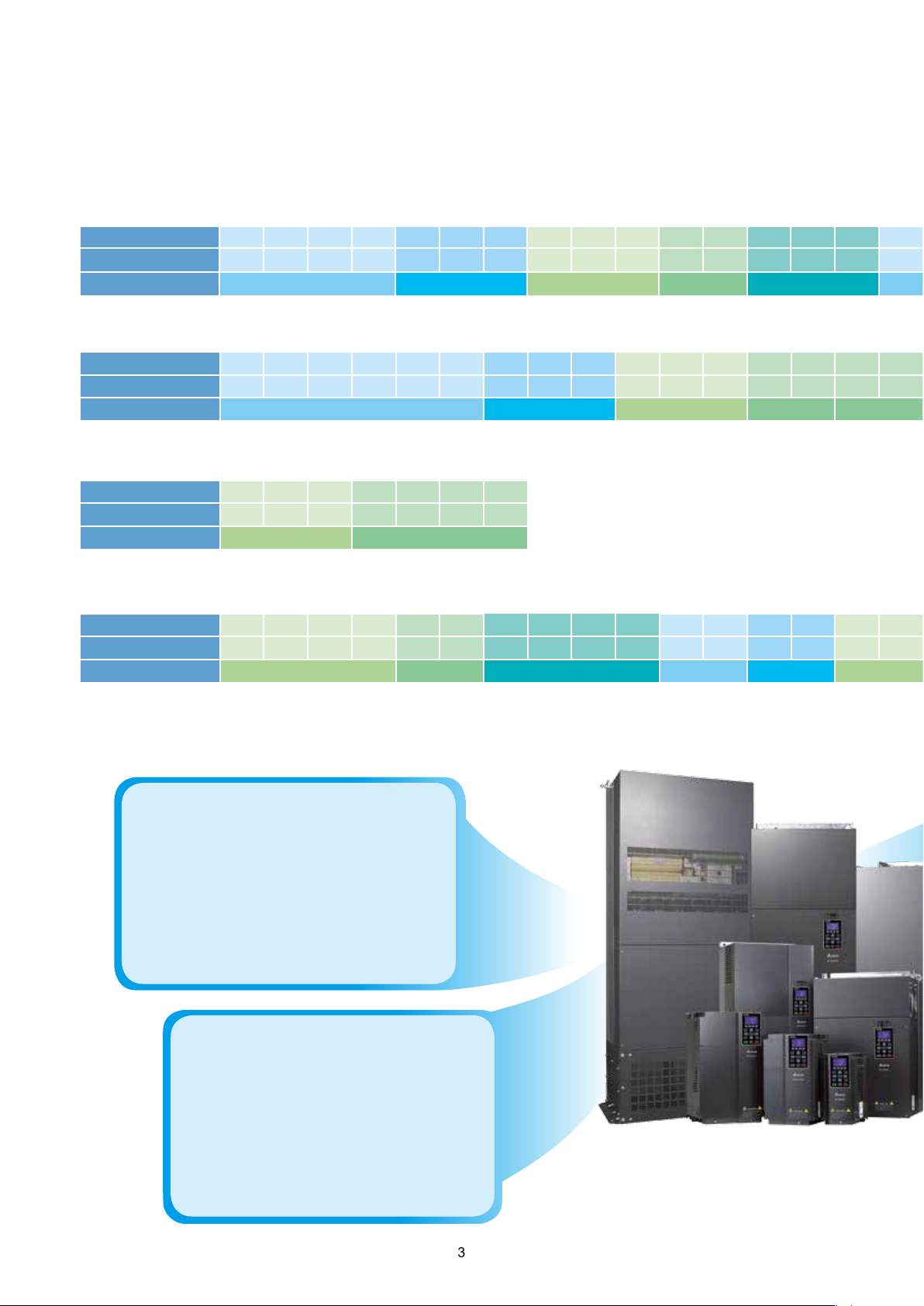
Standard Models (IP20/NEMA1)
Power range
230 V (kW) 0.75 1.5 2.2 3.7 5.5 7.5 11 15 18.5 22 30 37 45 55 75 90
230 V (HP) 1 2 3 5 7.5 10 15 20 25 30 40 50 60 75 100 125
Frame Size A B C D E F
Power range
460 V (kW) 0.75 1.5 2.2 3.7 4.0 5.5 7.5 11 15 18.5 22 30 37 45 55 75 90 110 132 160 185 220 280 315 355 450
460 V (HP) 1 2 3 5 5 7.5 10 15 20 25 30 40 50 60 75 100 125 150 175 215 250 300 375 425 475 600
Frame Size A B C D0 D E F G
Power range
575 V (kW)
575 V (HP)
Frame Size
Power range
690 V (kW)
690 V (HP)
Frame Size
:230 V 0.75 ~ 90 kW
:460 V 0.75 ~ 450 kW
: 575 V 1.5 ~ 15 kW
1.5 2.2 3.7 5.5 7.5 11 15
2 3 5 7.5 10 15 20
A B
: 690 V 18.5 ~ 630 kW
18.5 22 30 37 45 55 75 90 110 132 160 200
25 30 40 50 60 75 100 125 150 175 215 270 335 425 530 600 745 840
C D E F G H
315 400 450 560 630
250
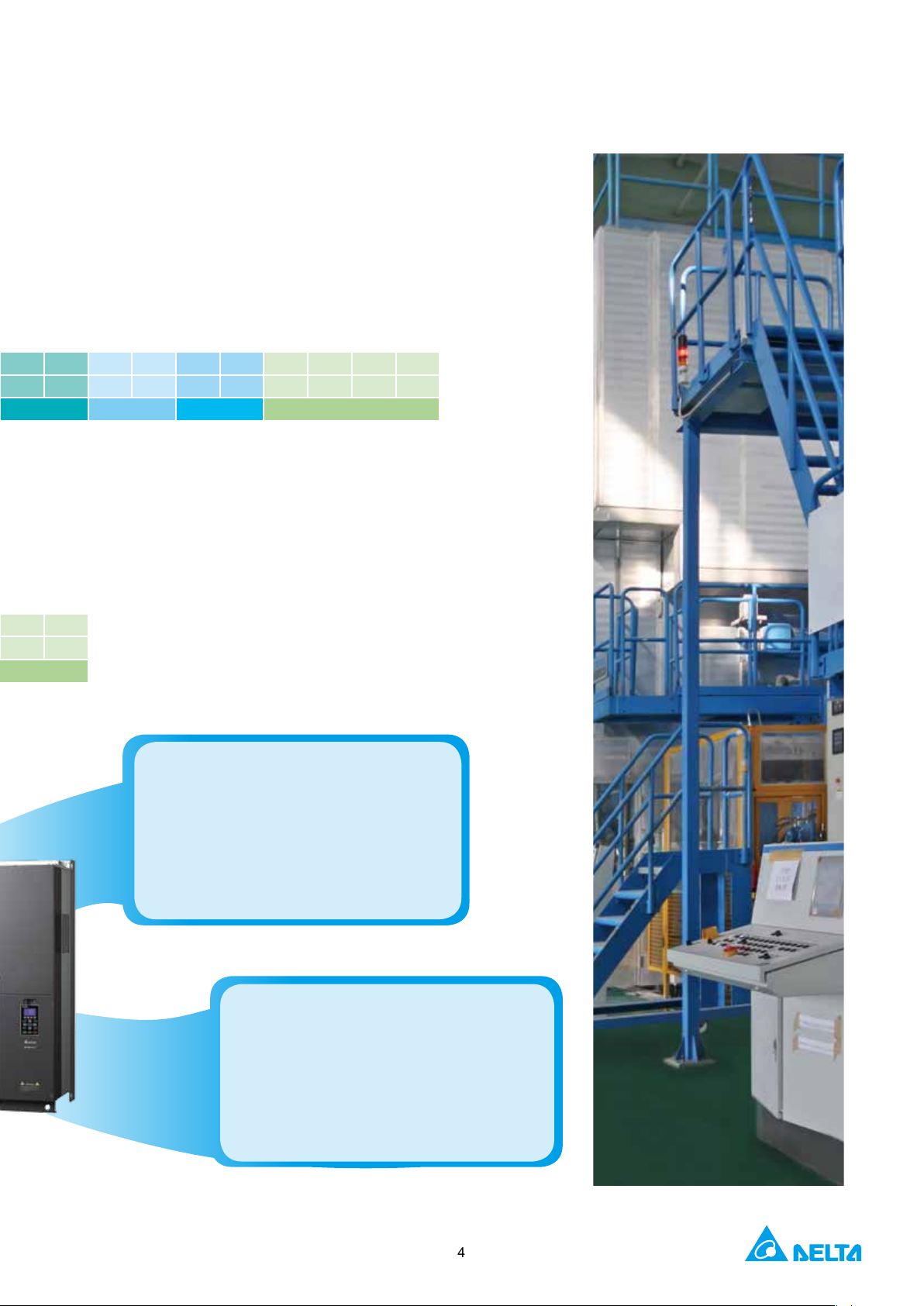
Advanced Drive Controls
▪
High Performance
1. High bandwidth control
2. Speed / torque / position control mode
3. Dual rating design
(normal duty / heavy duty)
4. 4-quadrant torque control and limit
5. For both synchronous and
asynchronous motors
▪
Environmental Adaptability
1. 50℃ operating temperature
2. Built-in DC reactor
3. Coated circuit boards
4. Built-in EMC lter
5. International safety standard
(CE/UL/cUL)
*Note: Please refer to the Product Specication
3
Page 5
H
▪
Versatile Drive Controls
1. Built-in safe stop function
2. Built-in PLC function
3. Built-in brake unit
4. Supports various network
protocols
5. Position control
▪
Modular Design
1. Hot pluggable LCD keypad
2. I/O extension cards
3. Various PG (encoder) feedback cards
4. Network cards for eldbus modules
5. Removable fan
4
Page 6
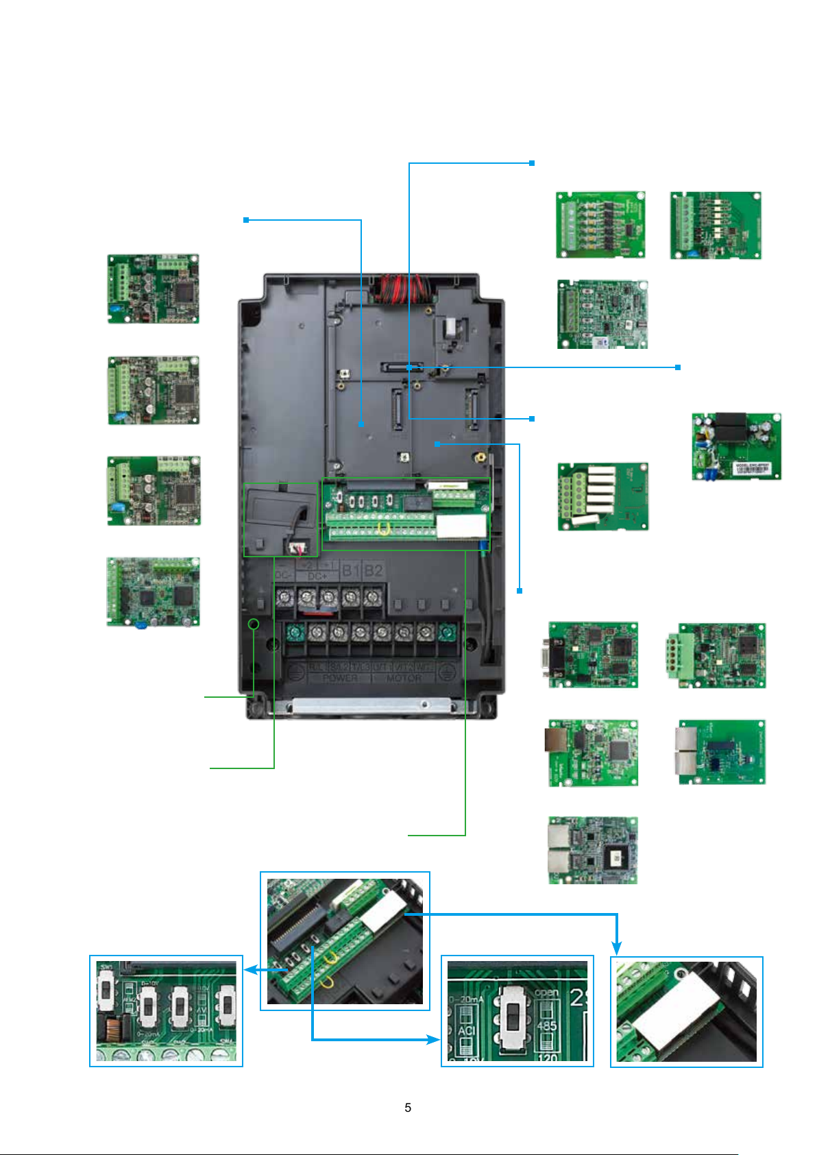
Modular Design
Various accessories options, such as I/O extension cards, encoder feedback cards, communication cards,
hot pluggable LCD keypad, removable terminals and removable fans.
►
I/O extension cards
EMC-D42AEMC-D611A
►
PG (Encoder) cards
EMC-PG01O / EMC-PG02O
EMC-A22A
EMC-PG01U / EMC-PG02U
►
24V Power
Shift Card
EMC-BPS01
►
Relay Extension
EMC-PG01L / EMC-PG02L
Card
EMC-R6AA
EMC-PG01R
■Removable fan
To ensure personal safety,
do not begin wiring before
the indicator light is off.
*NOTE: "u" are optional accessories.
■Power indicator
To prevent personal injury, please do not
perform wiring before power indicator is off.
■Removable terminals
Convenient wiring and safety equipment.
Analog I/O switch Termination resistor
►
Communication cards
CMC-PD01
CMC-MOD01 / CMC-EIP01 EMC-COP01
CMC-EC01
Dual RJ45
communication ports
CMC-DN01
5
Page 7
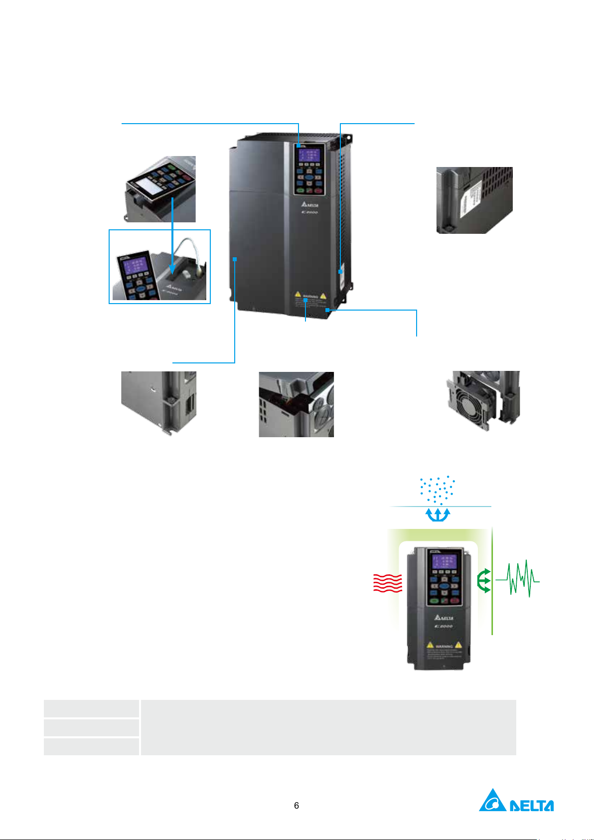
The modular design fullls the needs of system applications and equipment maintenance.
■
KPC-CC01 keypad
■
Standard RJ45 network cable for remote operation.
■
Easy to remove with one press.
■
RFI Jumper
■
Remove the safety screws and
press on both side tabs to remove
the cover.
■
The product nameplate shows
the input / output voltage,
input / output current, the
frequency range, and more.
■
Modular fan design, easy to
replace and clean, extending
product service life.
Excellent Environment Adaptability
►
Built-in DC choke to surpress harmonics*
►
Built-in EMC lter to lter noise*
►
Conformal coating (Class 3C3 of IEC60721-3-3 standard)
ensures drive operation stability and safety in critical environments.
►
The electronic components of the drive are isolated from the
cooling system to reduce heat interference. Dissipated heat can be
Heat
dissipation
discharged by ange-mounting installation, and forced fan cooling
can import cold air into the heat sink. The heat dissipation
performance is optimized by these two cooling methods.
*Note: Please refer to the Product Specication
Certifications
UL, cUL
C-Tick
ROHS
CE
Low Voltage: EN61800-5-1
EMC: EN61000-3-12, EN61800-3, IEC61000-6-2, IEC61000-6-4, IEC61000-4-2,
IEC61000-4-3, IEC61000-4-4, IEC61000-4-5, IEC61000-4-6, IEC61000-4-8
Dust-proof
Interference
immunity
6
Page 8
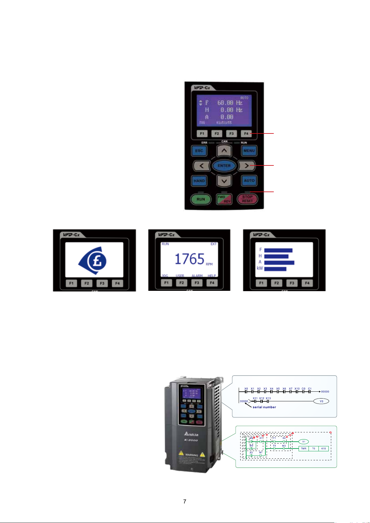
Quick and Easy Parameters Setting via the
LCD Keypad
■
Multi-column display for the drive status
■
Simple and intuitive operation
■
User-dened parameter groups
■
Real Time Clock and calendar function
■
Language selection for display
■
Copy function saves parameters and PLC
programs to the keypad memory for later
transfer to another drive
■
IP66 protection level
F1 to F4: User-dened
function keys
Selection keys
LED displays the
current drive status
Create homepage logo Editable message display Editable chart display
Intelligent PLC Functions
■
Built-in 10 K steps capacity of PLC
functions. Distributed control and
independent operation are easily
achieved via network connection.
■
CANopen Master protocol and PLC
functions provide synchronous control
and fast data exchange.
7
Page 9
High-Speed Network
►
Provides optional MODBUS RTU and various
eldbus cards for exible applications
■
■
CANopen
(DS402)
►
Advanced network functions
►
Built-in MODBUS communication
Ability to control up to 8 Slave drives via the CANopen Master function
•
Supports all Delta industrial automation products
(Built-in EDS les for all Delta industrial automation products)
•
I/O data congurations for each device on the CANopen network
•
Motion control planning function
•
WPL Soft
CANopen
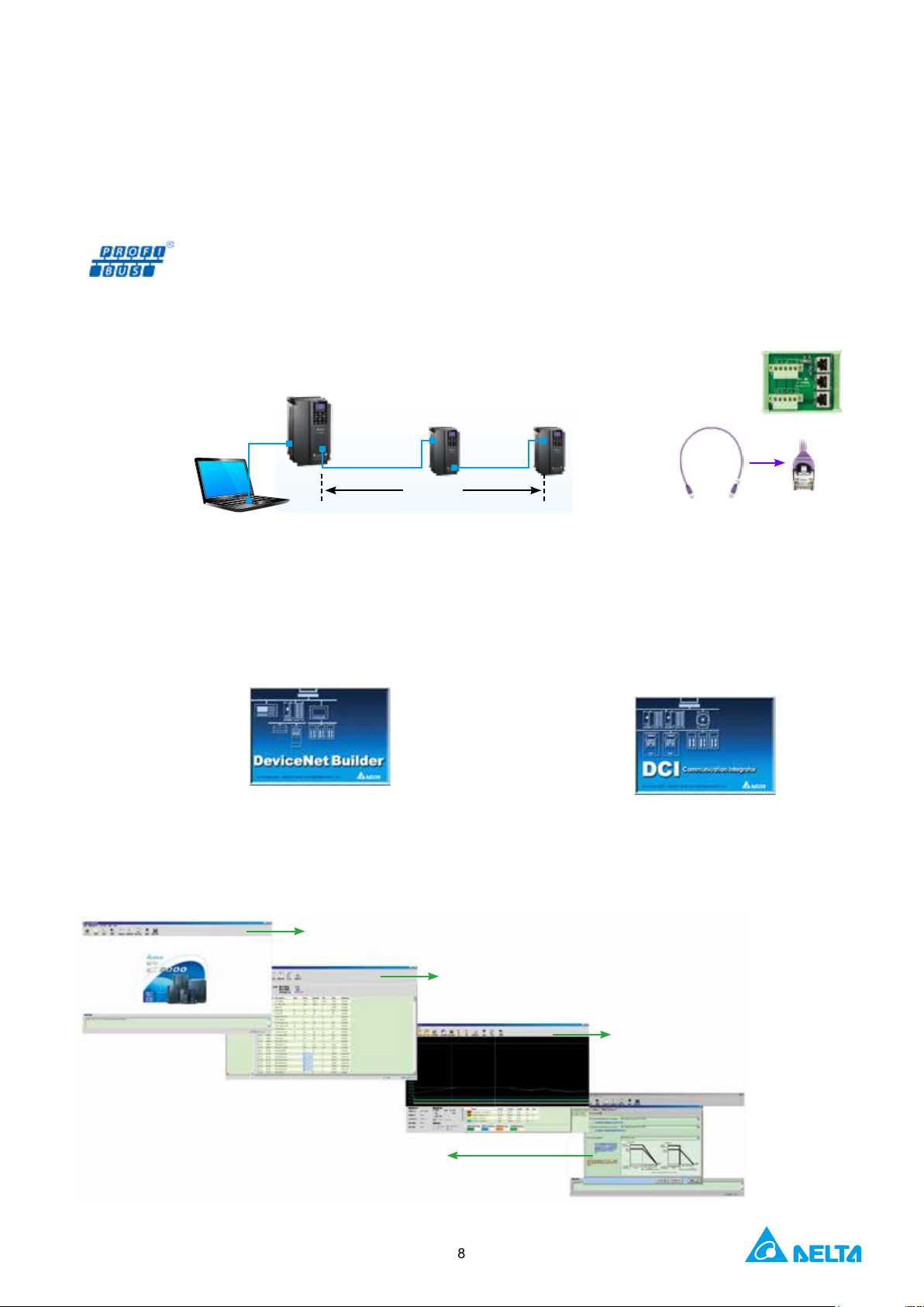
■
DeviceNet
Through the Delta specially designed DeviceNet
Builder software, users can easily establish
a standard DeviceNet control network by the
parameter pre-assignment function for each
equipment and remote I/O.
•
Supports all Delta industrial automation products
(Built-in EDS les for all Delta industrial automation
products)
•
I/O data congurations
for each device on the
DeviceNet network
•
DeviceNet layout software
1 Mbps 25 m
500 kbps 100 m
CANopen
■ EtherNet/IP
■
MODBUS TCP
Delta provides communication integrator software
that offers graphic module settings and a user friendly
interface to support all Ethernet products settings and
online monitoring.
•
Delta software for Ethernet/MODBUS TCP products
•
Graphic module settings and a user friendly interface
•
Auto search function
•
Supports Virtual
COM settings
•
TAP-CN03 distribution
box for long distances
•
RJ45 cable
Convenient Drive System Management Platform
■
Provides a complete operation platform for users' easy control and monitoring via PC, including parameters
save/setting, real-time wave monitor, quick setup, for multiple languages and with multi-language operation systems.
Start-up display
Displays horsepower, rated voltage and current of the drive in use.
Parameter management
Provides parameter setting/save/copy/comparison for
convenient parameter management.
Trend records
Monitors the drive operation form via network and
displays I/O terminal status. Useful for tasks such as
"trial run monitoring".
Quick setup
Guides the user step-by-step through the drive
settings according to quick setup wizard.
*NOTE: These software programs are available for download on Delta's website
8
Page 10

High-Performance Field Oriented Control
The FOC+PG mode of C2000 Series can output 150%
of starting torque at extremely low speeds for precise
and stable speed control.
Example for 3.7kW model
300
250
200
150
Torque(%)
100
50
0
-1 1 3 5 7 9 11
Frequency(Hz)
C type
0Hz
0.1Hz
0.5Hz
1Hz
2Hz
3Hz
5Hz
10Hz
Fast Response to
Impact Load
During load changes, the C2000 Series calculates the
required torque response and minimizes the vibration
caused by load impact using FOC.
100
80
60
40
20
0
-20
-40
Speed (RPM)
-60
-80
-100
150 200 250
100
300 350
Time
400 450 500
Precise position and speed control ideal for printing
machine applications.
Auto Energy-Saving
Operation
Auto-calculates the optimal voltage for the load
output using load power when under constant speed
operation.
Frequency Command = Frequency Output
Output Voltage
Output Current
Current < Rated Current * 0.35
5sec
Deceleration Energy Backup (DEB)
This function controls the motor deceleration to stop when power blinks off to prevent mechanical damage and
then accelerates to its original operation speed when power resumes.
Input Voltage
Motor Speed
Power Blink Off
DEB
Decelerate to Stop
Motor Flying Start
DEB Return Time
Time
9
Input Voltage
Motor Speed
Unexpected Power Shut Down
Safe Motor Stop
DEB
Decelerate to Stop
DEB Return Time
Time
Page 11
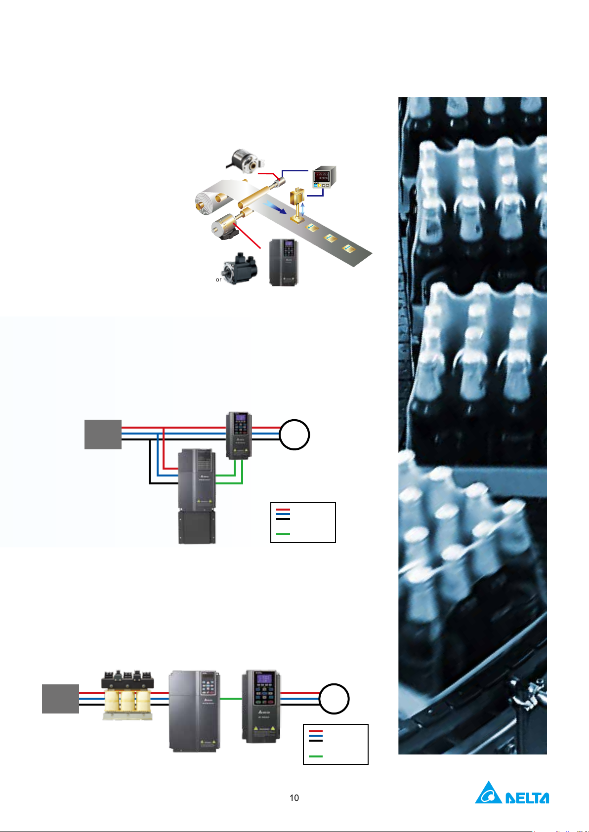
A Drive for Permanent Magnet
(PM) Motors
The C2000 is a dual mode drive to control
both an induction motor and permanent
magnet motor. The dynamic response
of a PM motor provides precise
control of position, speed
and torque.
Permanent magnet motor
Servo motor
Encoder
AC motor drive
Delta REG2000 Series for
Power Regeneration
Using the REG2000 with the C2000 in a crane and hoist application
provides the user with a four-quadrant operation and energy saving
results.
Mains
Power
M
Counter
AC Voltage
DC Voltage
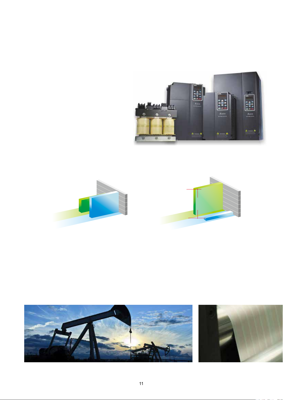
Delta AFE2000 Series for
Power Regeneration and
Power Quality Improvement
The Active Front End Unit (AFE2000) helps to reduce torque ripple and
harmonics with a higher power factor to provide excellent production
quality and outstanding energy saving results.
Mains
Power
10
M
AC Voltage
DC Voltage
Page 12
Delta Active Front End AFE2000 Series
Tr ad it io na l AC m ot o r d r iv e
Tr a d it i on al AC mo t or d r iv e
Features
■
Replaces traditional brake resistor to reduce heat generation.
■
Clear energy savings: more than 95% of the
regenerative energy is converted into electricity
and supplied back to the mains.
■
Full-load operation: input-side current THD lower than
5% and improves power factor up to 99%.
■
AC motor drives with AFE2000:
supports 4-quadrant operation with variable
frequencies and adjustable system.
■
Constant DC bus voltage: unaffected
by mains voltage uctuations.
Improves power factor and decreases harmonic distortion.
THD<=5%, power factor > 99%
60%
99%
80%
AF E 2 000
Improves power factor by 20%
Power
Foctor (%)
Decreases harmonic
distortion by 55%
5%
THD (%)
AF E 2000
Applications
■
Large-inertia loads, such as centrifuge equipment, dewatering machines and roving machines
■
4-quadrant loads including elevators, cranes and pumpjacks (oil extraction machines)
■
Quick braking, such as machine tools, bag making machines, auto storage and retrieval systems, and lathes
■
Long-term energy feedback, such as wind power, water power, steel printing and paper making machinery (winding
equipment)
■
Improves power quality for industries such as semiconductor and panel industries
11
Page 13
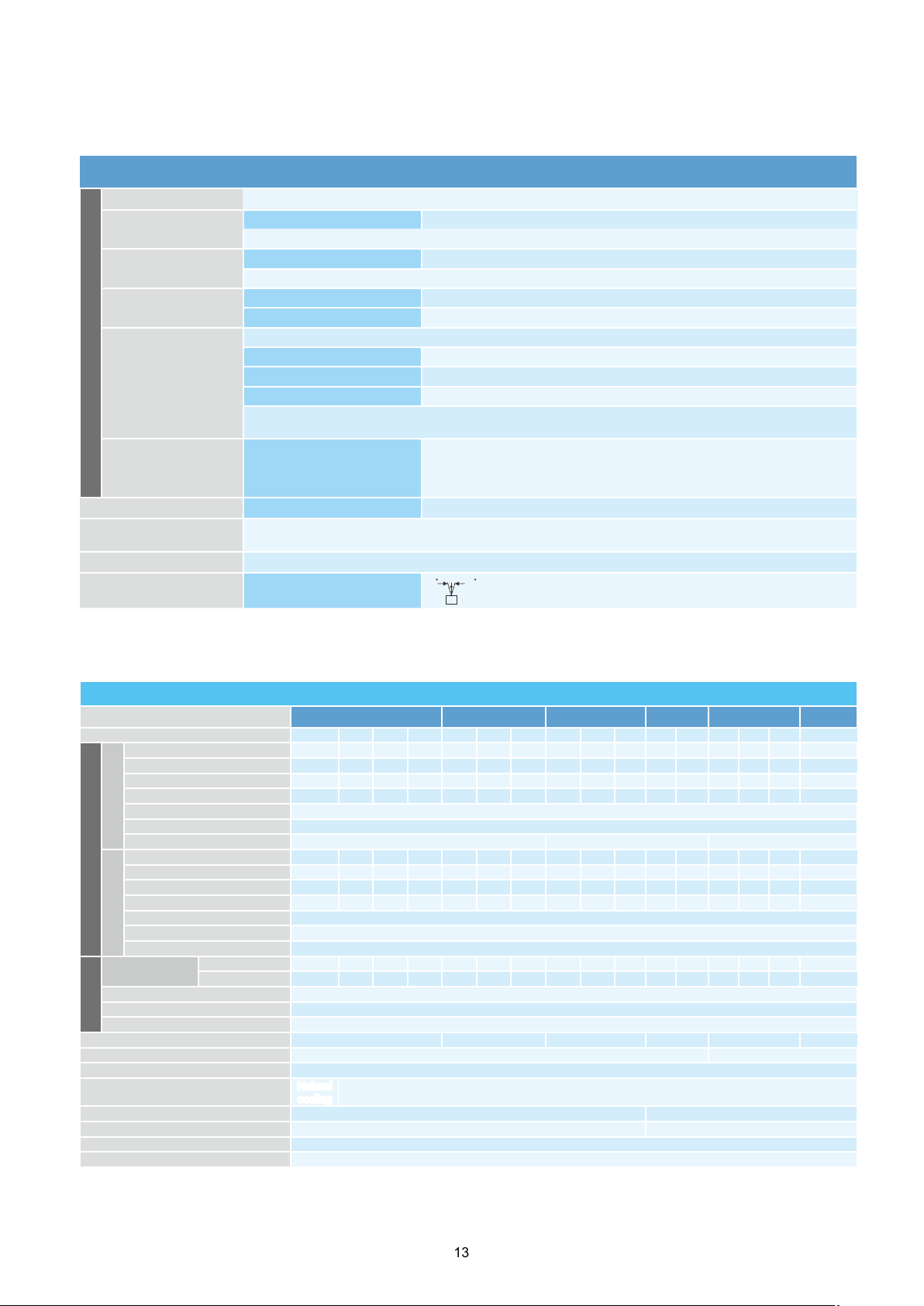
Operation Temperature and Protection Level
Model Frame Top Cover Conduit Box Protection Level OperationTemperature
VFDxxxCxxA
VFDxxxCxxS
VFDxxxCxxE
VFDxxxCxxU
VFDxxxC53A-21
VFDxxxC63B-21
VFDxxxC63B-21
Frame
A ~ C
230 V: 0.75 ~ 22 kW
460 V: 0.75 ~ 30 kW
Frame
D ~ H
230 V: > 22 kW
460 V: > 30 kW
Frame
A ~ C
460 V: 0.75 ~ 30 kW
Frame
D ~ H
230 V: > 22 kW
460 V: > 30 kW
Frame
A ~ C
1.5 ~ 37 kW
Frame
D ~ H
> 45 kW
Remove top cover
Standard with top
cover
N / A
Remove top cover
Standard with top
cover
N / A Standard conduit box IP20 / UL Type1 / NEMA1 -10 ºC ~ 40 ºC
Remove top cover
Standard with top
cover
N / A Standard conduit box IP20 / UL Type1 / NEMA1 -10 ºC ~ 40 ºC
Standard conduit plate
No conduit box
Standard conduit plate
Standard conduit plate
IP20 / UL Open Type -10 ºC ~ 50 ºC
IP20 / UL Type1 / NEMA1 -10 ºC ~ 40 ºC
IP00
IP20 / UL Open Type
Protection degree for
the circled area is IP00,
other areas are IP20
IP20 / UL Open Type -10 ºC ~ 50 ºC
IP20 / UL Type1 / NEMA1 -10 ºC ~ 40 ºC
IP20 / UL Open Type -10 ºC ~ 50 ºC
IP20 / UL Type1 / NEMA1 -10 ºC ~ 40 ºC
-10 ºC ~ 50 ºC
VFDxxxC63B-00
Frame
> 45 kW
D ~ H
N / A
No conduit box
IP00
IP20 / UL Open Type
Protection degree for
the circled area is IP00,
other areas are IP20
-10 ºC ~ 50 ºC
12
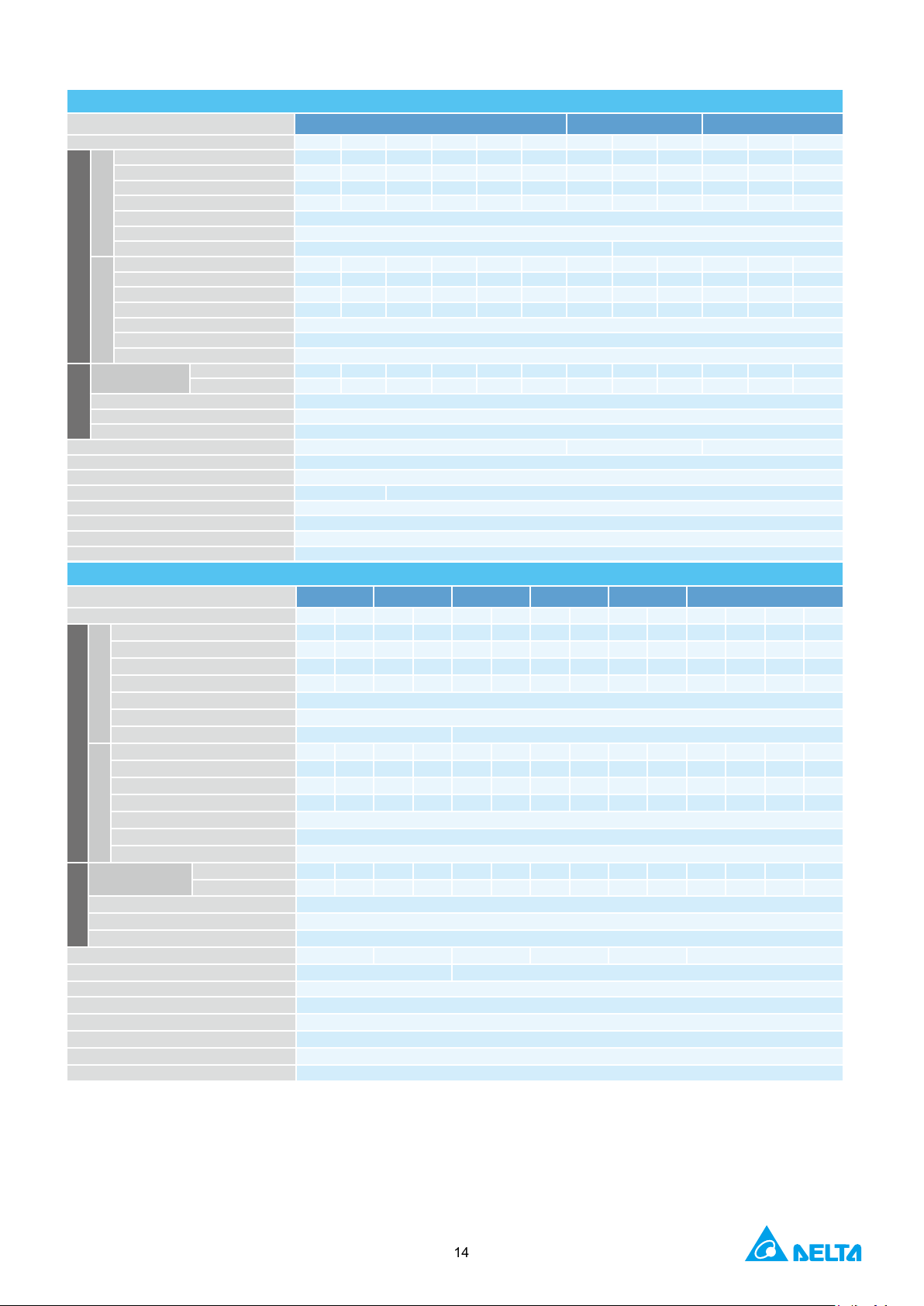
Page 14
230 V
A
BCDEF
Model VFD- ���C��
007
015
022
Rated Output Capacity (kVA)
Rated Output Current (A)
Applicable Motor Output (kW)
Applicable Motor Output (HP)
Overload Capacity
Max. Output Frequency (Hz)
Carrier Frequency (kHz)
Rated Output Capacity (kVA)
1.9
2.8
4.0
6.4
9.612192528344555688196
131
Rated Output Current (A)
4.8
Applicable Motor Output (kW)
Applicable Motor Output (HP)
Overload Capacity
Max. Output Frequency (Hz)
Carrier Frequency (kHz)
Input Rating
Normal Duty
Heavy Duty
Rated Voltage / Frequency
Operating Voltage Range
Frequency Tolerance
Drive Weight (Kg)
Efciency (%)
Power Factor
Natural
cooling
Braking Chopper
Frame A, B, C: built-in
Frame D and above: optional
DC Choke
Frame A, B, C: optional
Frame D and above: built-in
EMC Filter
Optional
EMC-COP01
Optional
Environment for Operation, Storage and
DO NOT expose the AC motor drive to harsh environments, such as dust, direct sunlight, corrosive / ammable gasses, humidity, liquid or vibrations.
10 1 0
Transportation
The salts in the air must be less than 0.01 mg / cm2 per year.
Installation Location
Surrounding
Temperature (°C)
Rated Humidity
Air Pressure
Environment
Pollution Level
Altitude
Package Drop
Vibration
Impact
Operation Position
(kPa)
IEC60364-1 / IEC60664-1 Pollution degree 2, indoor use only
Storage / Transportation
Only allowed in non-condensation, non-frost, non-conductive environment.
Operation/Storage / Transportation Max. 95%
Only allowed in non-condensation, non-frost, non-conductive environment.
Operation / Storage 86
Transportation 70
I
EC60721-3-3
Operation
Storage
Transportation
If the AC motor drive is to be used under harsh environment with high level of contamination (e.g. dew, water, dust), make
sure it is installed in an environment qualied for IP54 such as in a cabinet.
Operation
Storage / Transportation ISTA procedure 1 A (according to weight) IEC60068-2-31
1.0 mm, peak to peak value range from 2 Hz to 13.2 Hz; 0.7 G ~ 1.0 G range from 13.2 Hz to 55 Hz;
1.0 G range from 55 Hz to 512 Hz. Comply with IEC 60068-2-6.
IEC / EN 60068-2-27
Max. allowed offset angle ±10 °
(under normal installation position)
-25 ~ 70
106
~
106
~
Class 3C3; Class 3S2
Class 1C2; Class 1S2
Class 2C2; Class 2S2
If the AC motor drive is installed at an altitude 0 ~ 1000 m, follow normal operation
restriction. If it is installed at altitude 1000 ~ 2000 m, decrease 1% of rated current or lower 0.5 °C
of temperature for every 100 m increase in altitude. Maximum altitude for Corner Grounded TN
system is 2000m, for application over 2000m please contact Delta for more details.
Specifications
Frame Size
*
NORMAL DUTY
Output Rating
HEAVY DUTY
Input Current (A)
Cooling Method
2.0 3.2 4.4 6.8 10 13 20 26 30 36 48 58 72 86 102 138
5 8 11 17 25 33 49 65 75 90 120 146 180 215 255 346
0.75 1.5 2.2 3.7 5.5 7.5 11 15 18.5 22 30 37 45 55 75 90
1 2 3 5 7.5 10 15 20 25 30 40 50 60 75 100 120
120% of rated current: 1 minute for every 5 minutes; 160% of rated current: 3 seconds for every 30 seconds
2 ~ 15 (default setting 8) 2 ~ 10 (default setting 6) 2 ~ 9 (default setting 4)
7.1 10 16 24 31 47 62 71 86 114 139 171 204 242 329
0.4 0.75 1.5 2.2 3.7 5.5 7.5 11 15 19 22 30 37 45 55 75
0.5 1 2 3 5 7.5 10 15 20 25 30 40 50 60 75 100
150% of rated current: 1 minute for every 5 minutes; 180% of rated current: 3 seconds for every 30 seconds
6.4 12 16 20 28 36 52 72 83 99 124 143 171 206 245 331
6.1 11 15 18.5 26 34 50 68 78 95 118 136 162 196 233 315
2.6 ± 0.3 5.4 ± 1 9.8 ± 1.5 38.5 ± 1.5 64.8 ± 1.5 86.5± 1.5
037 055 075 110 150 185 220 300 370 450 550 750 900
0.00 ~ 599.00
0.00 ~ 300.00
2 ~ 6 (default setting 2)
3-phase AC 200 V ~ 240 V (-15% ~ +10%), 50 / 60 Hz
97.8 98.2
170 ~ 264V
47 ~ 63 Hz
> 0.98
Fan cooling
ac
* The factory setting is Normal Duty mode
13
Page 15
460 V
Frame Size
Model VFD-���C��
007
015
022
Rated Output Capacity (kVA)
Rated Output Current (A)
Applicable Motor Output (kW)
Applicable Motor Output (HP)
Overload Capacity
Max. Output Frequency (Hz)
Carrier Frequency (kHz)
Rated Output Capacity (kVA)
2.3
3.0
4.5
6.5
7.6
9.6141824293445
Rated Output Current (A)
2.9
Applicable Motor Output (kW)
Applicable Motor Output (HP)
Overload Capacity
Max. Output Frequency (Hz)
Carrier Frequency (kHz)
Input Rating
Normal Duty
Heavy Duty
Rated Voltage / Frequency
Operating Voltage Range
Frequency Tolerance
Drive Weight (Kg)
Efciency (%)
Power Factor
Cooling Method
Natural cooling
Fan cooling
Braking Chopper
Frame A, B, C: built-in; Frame D and above: optional
DC Choke
Frame A, B, C: optional; Frame D and above: built-in
EMC Filter
VFDXXXC43A: Optional; Frame A~C VFDXXXC43E: Built-in
EMC-COP01
VFDXXXC43A: optional; VFDXXC43E: built-in
460 V
Model VFD-���C��
370
450
550
*
Rated Output Capacity (kVA)
Rated Output Current (A)
Applicable Motor Output (kW)
Applicable Motor Output (HP)
Overload Capacity
Max. Output Frequency (Hz)
Carrier Frequency (kHz)
Rated Output Capacity (kVA)
556984
114
136
167
197
235
280
348
417
466
517
677
Rated Output Current (A)
69
Applicable Motor Output (kW)
Applicable Motor Output (HP)
Overload Capacity
Max. Output Frequency (Hz)
Carrier Frequency (kHz)
Normal Duty
Heavy Duty
Rated Voltage / Frequency
Operating Voltage Range
Frequency Tolerance
Drive Weight (Kg)
Efciency (%)
Power Factor
> 0.98
Cooling Method
Fan cooling
Braking Chopper
Frame A, B, C: built-in; Frame D and above: optional
DC Choke
Frame A, B, C: optional; Frame D and above: built-in
EMC Filter
Frame D0~H: Optional
EMC-COP01
VFDXXXC43A: optional; VFDXXC43E: built-in
*
NORMAL DUTY
Output Rating
HEAVY DUTY
Input Current (A)
A B C
2.4 3.2 4.8 7.2 8.4 10 14 19 25 30 36 48
3.0 4.0 6.0 9.0 10.5 12 18 24 32 38 45 60
0.75 1.5 2.2 3.7 4.0 5.5 7.5 11 15 18.5 22 30
1 2 3 5 5 7.5 10 15 20 25 30 40
120% of rated current: 1 minute for every 5 minutes; 160% of rated current: 3 seconds for every 30 seconds
2 ~ 15 (default setting 8) 2 ~ 10 (default setting 6)
3.8 5.7 8.1 9.5 11 17 23 30 36 43 57
0.4 0.75 1.5 2.2 3.7 4.0 5.5 7.5 11 15 18.5 22
0.5 1 2 3 5 5 7.5 10 15 20 25 30
150% of rated current: 1 minute for every 5 minutes; 180% of rated current: 3 seconds for every 30 seconds
4.3 5.9 8.7 14 15.5 17 20 26 35 40 47 63
4.1 5.6 8.3 13 14.5 16 19 25 33 38 45 60
037 040 055 075 11 0 150 185 220 300
0.00 ~ 599.00
0.00 ~ 300.00
2 ~ 6 (default setting 2)
3-phase AC 380 V ~ 480 V ( -15% ~ +10%), 50 / 60 Hz
323 ~ 528 V
AC
47 ~ 63 Hz
2.6 ± 0.3 5.4 ± 1 9.8 ± 1.5
97.8
> 0.98
Frame Size
NORMAL DUTY
Output Rating
HEAVY DUTY
Input Current (A)
Input Rating
D0 D E F G H
750 900 1100 1320 1600 1850 2200 2800 3150 3550 4500
58 73 88 120 143 175 207 247 295 367 438 491 544 720
73 91 11 0 150 180 220 260 310 370 460 550 616 683 866
37 45 55 75 90 11 0 132 160 185 220 280 315 355 450
50 60 75 100 125 150 175 215 250 300 375 420 475 600
120% of rated current: 1 minute for every 5 minutes; 160% of rated current: 3 seconds for every 30 seconds
0.00 ~ 599.00
2 ~ 10 (default setting 6) 2 ~ 9 (default setting 4)
86 105 143 171 209 247 295 352 437 523 585 649 815
30 37 45 55 75 90 11 0 132 160 185 220 280 315 355
40 53 60 75 100 125 150 175 215 250 300 375 425 475
150% of rated current: 1 minute for every 5 minutes; 180% of rated current: 3 seconds for every 30 seconds
0.00 ~ 300.00
2 ~ 6 (default setting 2)
74 101 114 157 167 207 240 300 380 400 494 555 625 866
70 96 108 149 159 197 228 285 361 380 469 527 594 815
3 - phase AC 380 V ~ 480 V (-15% ~ +10% ), 50 / 60 Hz
323 ~ 528 V
47 ~ 63 Hz
27 ± 1.5 38.5 ± 1.5 64.8 ± 1.5 86.5 ± 1.5 134 ± 4 228
97.8 98.2
AC
* The factory setting is Normal Duty mode
NOTES
1) The carrier frequency is default. Increasing the carrier frequency requires a reduction in current. please refer to Pr. 06-55 Derating Protection drawing.
2) The AC motor drive should operate in derating current when its control method is set to FOC Sensorless, TQC+PG, TQC sensorless. PM+PG, PM sensorless. Please refer to Pr. 06-55 for more information.
3) Select the AC motor drive with capacity one grade larger for the impact load application.
4) The rated input current will be affected not only by Power Transformer and the connection of the reactors on input side, but also fluctuates with the impedance of power side.
5) For Frame A, B and C, Model VFDXXXC43A is under IP20 / NEMA1 / UL TYPE1 protection level.
6) For Frame D and above, if the last character of the model is A then it is under IP20 protection level but the wiring terminal is under IP00 protection level;
7) if the last character of the model is E, it is under IP20 / NEMA1 / UL TYPE1 protection level.
14
Page 16

Frame Size
Model VFD-���C53A-21
Light Duty
Rated Output Capacity (kVA)
Rated Output Current (A)
Applicable Motor Output (kW)
Applicable Motor Output (HP)
Rated Output Capacity (kVA)
Applicable Motor Output (kW)
0.75
1.5
2.2
3.7
5.5
7.5
11
Rated Output Capacity (kVA)
Rated Output Current (A)
Applicable Motor Output (kW)
Applicable Motor Output (HP)
Carrier Frequency (kHz)
Light Duty
Normal Duty
Heavy Duty
Rated Voltage / Frequency
Operating Voltage Range
446 ~ 660 VAC
Frequency Tolerance
47 ~ 63 Hz
Efciency (%)
97
98
Power Factor
> 0.98
AC Drive Weight (Kg)
3 ± 0.3
4.8 ± 1
Braking Chopper
Built-in
DC Choke
Optional
EMC Filter
Optional
Model VFD-���C63B-00 / -21
Rated Output Capacity (kVA)
Applicable Motor Output ( 690V, kW)
Applicable Motor Output ( 690V, HP)
Applicable Motor Output (575V, HP)
Rated Output Current (A)
Rated Output Capacity (kVA)
Applicable Motor Output ( 690V, kW)
15
18.522303745557590110
Applicable Motor Output ( 690V, HP)
Applicable Motor Output (575V, HP)
1520253040506075100
125
Rated Output Current (A)
Rated Output Capacity (kVA)
Applicable Motor Output ( 690V, kW)
Applicable Motor Output ( 690V, HP)
1520253040506075100
125
Applicable Motor Output (575V, HP)
Rated Output Current (A)
Carrier Frequency (kHz)
Light Duty
Normal Duty
Heavy Duty
Rated Voltage / Frequency
Operating Voltage Range
446 ~ 759 VAC
Frequency Tolerance
47 ~ 63 Hz
Efciency (%)
97
Power Factor
> 0.98
AC Drive Weight (Kg)
10 ± 1.5
39 ± 1.5
61 ± 1.5
Cooling Method
Fan cooling
Braking Chopper
Frame C (built-in)
Frame D and above (optional)
DC Choke
Frame C (optional)
Frame D and above (built-in)
EMC Filter
Optional
*
Rated Output Current (A)
575 V
A B
015 022 037 055 075 110 150
3 4.3 6.7 9.9 12.1 18.7 24.1
3 4.3 6.7 9.9 12.1 18.7 24.2
1.5 2.2 3.7 5.5 7.5 11 15
2 3 5 7.5 10 15 20
2.5 3.6 5.5 8.2 10 15.4 19.9
2.5 3.6 5.5 8.2 10 15.5 20
Applicable Motor Output (HP)
Normal Duty
Output
Heavy Duty
Input Current (A)
Input
Cooling Method Natural cooling Fan cooling
1 2 3 5 7.5 10 15
2.1 3 4.6 6.9 8.3 12.9 16.7
2.1 3 4.6 6.9 8.3 13 16.8
0.75 1.5 2.2 3.7 3.7 7.5 7.5
1 2 3 5 5 10 10
3.8 5.4 10.4 14.9 16.9 21.3 26.3
3.1 4.5 7.2 12.3 15 18 22.8
2.6 3.8 5.8 10.7 12.5 16.9 19.7
-Phase
3
2 ~15 (default setting 4)
525 VAC ~ 600 V
( -15% ~ +10%), 50 / 60 Hz
AC
690 V
Frame Size
Light Duty
*
185 220 300 370 450 550 750 900 1100 1320
29 36 43 54 65 80 103 124 149 179
18.5 22 30 37 45 55 75 90 11 0 132
25 30 40 50 60 75 100 125 150 175
20 25 30 40 50 60 75 100 125 150
24 30 36 45 54 67 86 104 125 150
24 29 36 43 54 65 80 103 124 149
20 25 30 40 50 60 75 100 125 150
C D E
Output
Normal Duty
Heavy Duty
Input Current (A)
Input
* Parameter 00-16; available load modes: Light Duty (LD), Normal Duty (ND) and Heavy Duty (HD); default setting is LD mode
20 24 30 36 45 54 67 86 104 125
17 24 29 36 43 54 65 80 103 124
11 15 18.5 22 30 37 45 55 75 90
10 15 20 25 30 40 50 60 75 100
14 20 24 30 36 45 54 67 86 104
29 36 43 54 65 81 84 102 122 147
24 29 36 43 54 65 66 84 102 122
20 24 29 36 43 54 53 66 84 102
3-Phase 525 VAC ~ 690 V
2 ~ 9 (default setting 4)
( -15% ~ +10%), 50 / 60 Hz
AC
15
Page 17

Frame Size
Model VFD-���C63B-00 / -21
*
Light Duty
Rated Output Capacity (kVA)
Applicable Motor Output ( 690V, kW)
Applicable Motor Output ( 690V, HP)
Applicable Motor Output (575V, HP)
Rated Output Current (A)
Normal Duty
Rated Output Capacity (kVA)
Applicable Motor Output ( 690V, kW)
132
160
200
250
315
355
450
630
Applicable Motor Output ( 690V, HP)
Applicable Motor Output (575V, HP)
150
175
200
250
350
400
450
745
Rated Output Current (A)
Heavy Duty
Rated Output Capacity (kVA)
Applicable Motor Output ( 690V, kW)
Applicable Motor Output ( 690V, HP)
Applicable Motor Output (575V, HP)
Rated Output Current (A)
Light Duty
Normal Duty
Heavy Duty
Rated Voltage / Frequency
Operating Voltage Range
446 ~ 759 VAC
Frequency Tolerance
47 ~ 63 Hz
Efciency (%)
97
98
Power Factor
> 0.98
AC Drive Weight (Kg)
88 ± 1.5
135 ± 4
243 ± 5
Cooling Method
Fan cooling
Braking Chopper
Frame D and above (optional)
DC Choke
Frame D and above (built-in)
EMC Filter
Optional
690 V
F G H
1600 2000 2500 3150 4000 4500 5600 6300
215 263 347 418 494.5 534.7 678.5 776
160 200 250 315 400 450 560 630
215 270 335 425 530 600 745 850
175 200 250 350 400 450 500 745
180 220 290 350 430 465 590 675
179 215 239 347 402.5 442.7 534.7 776
175 215 270 335 425 475 600 850
Output
Carrier Frequency (kHz)
Input Current (A)
Input
* Parameter 00-16; available load modes: Light Duty (LD), Normal Duty (ND) and Heavy Duty (HD); default setting is LD mode
150 180 220 290 350 385 465 675
149 179 215 263 333.5 356.5 483 776
110 132 160 200 250 280 400 630
150 175 215 270 335 375 530 850
125 150 175 200 250 335 450 745
125 150 180 220 290 310 420 675
2 ~ 9 (default setting 4) 2 ~ 9 (default setting 3)
178 217 292 353 454 469 595 681
148 178 222 292 353 388 504 681
123 148 181 222 292 313 423 681
-Phase
3
525 VAC ~ 690 V
( -15% ~ +10%), 50 / 60 Hz
AC
16
Page 18

General Specifications
Control Method
Starting Torque
V / F Curve
Speed Response Ability
Max. Output Frequency (Hz)
Frequency Output Accuracy
Frequency Setting Signal
Accel. / decel. Time
Over-Temperature Protection
Stall Prevention
Restart after Instantaneous
Power Failure
Grounding Leakage Current
Protection
Pulse Width Modulated (PWM)
model:
model
:
model: Normal duty 160%, heavy duty 180% of torque current
model
: Maximum 200% of torque current
Normal duty:
±0.01%, -10 ° C ~ +40 ° C,
model
:
model
:
model
: PWM
model: Over-current protection for
model
: Over-current protection for 225% rated current (Normal duty)
(
Heavy duty: around 202% ~ 210%
Control Mode
Torque Limit
Torque Accuracy at TQC Mode
Output Frequency Resolution
Overload Capacity
Control Characteristics
Main Control Function
Fan Control
Motor Protection
Over-current Protection
Over-Voltage Protection
Protection Characteristics
Short-circuit Current Rating (SCCR)
230 V / 460 V
1: V / F,2: SVC,3: VF+PG,4: FOC+PG,5: TQC+PG,6: PM+PG,7: FOC sensorless,8: TQC sensorless,
9: PM sensorless
575 V / 690 V
1: V / F,2: V / F+PG,3: SVC
Reach up to 150% or above at 0.5 Hz. Under FOC+PG mode, starting torque can reach 150% at 0 Hz
4-point adjustable V / F curve and square curve
5 Hz (vector control can reach up to 40 Hz)
230 V / 460 V
575 V / 690 V
TQC + PG:±5%
TQC Sensorless:±15%
Light Duty /
Digital command:
Digital command: 0.01 Hz, Analog command: 0.03 * max. output frequency / 60 Hz (±11 bit)
230 V / 460 V
Normal duty: 120% of rated current can endure for 1 minute during every 5 minutes ;
160% of rated current can endure for 3 seconds during every 30 seconds
Heav y duty: 150% of rated current can endure for 1 minute during every 5 minutes ;
180% of rated current can endure for 3 seconds during every 30 seconds
575 V / 690 V
Light duty: 120% of rated current can endure for 1 minute
Normal duty: 120% of rated current can endure for 1 minute, 150% can endure for 3 seconds
Heavy duty: 150% of rated current can endure for 1 minute, 180% can endure for 3 seconds
+10 V ~ -10V, 0 ~ +10 V, 4 ~ 20 mA, 0 ~ 20 mA,
0.00 ~ 600.00 / 0.0 ~ 6000.0
Torque control, Speed / torque control switching, Feed forward control, Zero-servo control,
Momentary power loss ride thru, Speed search, Over-torque detection, Torque Limit, 16-step speed (Max.),
Accel / decel time switch, S-curve accel / decel, 3-wire sequence, Auto-Tuning (rotational, stationary), Dwell,
Slip compensation, Torque compensation, JOG frequency, Fault restart,
Frequency upper / lower limit settings, DC injection braking at start / stop, High slip braking, Parameter copy
PID control (with sleep function), Energy saving control, MODOBUS communication (RS-485 RJ45, Max.
115.2 kbps)
230 V model:
VFD150C23A (include) and series above: PMW control; VFD110C23A and below: on / off switch control
460 V model:
VFD185C43A (include) and series above: PMW control; VFD150C43A and below: on / off switch control
575 V / 690 V
Electronic thermal relay protection
230 V / 460 V
Current clamp (Normal duty: around 170 ~ 175%); (Heavy duty: around 180 ~ 185%)
575 V / 690 V
Current clamp (Light duty: around 128 ~ 141%
The C2000 Series will shut down under below conditions:
230 V: DC bus over 410 V; 460 V: DC bus over 820 V; 575 V / 690 V: DC bus over 1189 V
Built-in temperature sensor
Stall prevention during acceleration, deceleration and running independently
Parameter setting up to 20 seconds
Leakage current is higher than 50% of rated current of the AC motor drive
Per UL508C, the drive is suitable for use on a circuit capable of delivering not more than 100kA symmetrical
amperes (rms) when protected by fuses given in the fuse table
0.01 ~ 599.00 Hz;
Seconds
control
Heavy duty:
Analog command:
pulse input
); (
0.00 ~ 300.00 Hz
±0.1%, 25 ±10 ° C
240% of rated current (Normal duty)
Normal duty: around 170 ~ 175%);
)
;
International Certications
Note: EAC Certification is for 230V and 460V models only
17
Page 19

Wiring
Wiring Diagram for Frame A ~ C
*Input: 3-phase power
NOTE
It is not recommended to use a power capacitor or automatic power factor regulator (APFR) at the power input side. If the system requires such a device, please
make sure a reactor is installed between the drive and the power capacitor or APFR.
18
Page 20

Wiring Diagram for Frame D ~ F
*Input: 3-phase power
19
Page 21

Wiring Diagram for Frame G ~ H
*Input: 3-phase power
NOTE
It is not recommended to use a power capacitor or automatic power factor regulator (APFR) at the power input side. If the system requires such a device, please
make sure a reactor is installed between the drive and the power capacitor or APFR.
20
Page 22

MODEL
FRAME_A
Dimensions
FrameWHDW1
H1
D1*
ØØ1Ø2
Ø3
Digital Keypad
Frame A
Unit: mm [inch]
VFD007C23A
VFD015C23A
VFD022C23A
VFD037C23A
VFD007C43A / 43E
VFD015C43A / 43E
VFD022C43A / 43E
VFD037C43A / 43E
VFD040C43A / 43E
VFD055C43A / 43E
VFD015C53A-21
VFD022C53A-21
VFD037C53A-21
mm 130.0 250.0 170.0 116.0 236.0 45.8 6.2 22.2 34.0 28.0
A1
inch 5.12 9.84 6.69 4.57 9.29 1.80 0.24 0.87 1.34 1.10
*D1: Flange mount.
21
Page 23

Frame B
Frame
WHDW1H1
D1*S1Ø1Ø2Ø3
MODEL
mm
MODEL
VFD055C23A
VFD075C23A
VFD110C23A
VFD075C43A / 43E
VFD110C43A / 43E
VFD150C43A / 43E
VFD055C53A-21
VFD075C53A-21
VFD110C53A-21
VFD150C53A-21
mm 190.0 320.0 190.0 173.0 303.0 77.9 8.5 22.2 34.0 28.0
B1
inch 7.48 12.60 7.48 6.81 11.93 3.07 0.33 0.87 1.34 1.10
See Detail A
See Detail B
Detail A (Mounting Hole)
Detail B (Mounting Hole)
*D1: Flange mount.
Frame C
VFD150C23A
See Detail A
See Detail B
VFD185C23A
VFD220C23A
VFD185C43A / 43E
VFD220C43A / 43E
VFD300C43A / 43E
Detail A (Mounting Hole)
VFD185C63B-21
VFD220C63B-21
VFD300C63B-21
VFD370C63B-21
Detail B (Mounting Hole)
Frame W H D W1 H1 D1* S1 Ø1 Ø2 Ø3
C1
inch 9.84 15.75 8.27 9.09 15.00 3.66 0.33 0.87 1.34 1.97
250.0 400.0 210.0 231.0 381.0 92.9 8.5 22.2 34.0 50.0
*D1: Flange mount.
22
Page 24

Frame D
mm
mm
MODEL
FRAME_D1
FRAME_D0-1
W
W1
SEE DETAIL A
D
D1
D2
SEE DETAIL B
S1S1
DETAIL A
(MOUNTING HOLE)
VFD300C23A
VFD370C23A
VFD550C43A
VFD750C43A
VFD450C63B-00
VFD550C63B-00
Frame W H D W1 H1 H2 H3 D1* D2 S1 S2 Ø1 Ø2 Ø3
D1
inch 12.99 - 10.83 11.22 21.65 20.67 19.37 4.22 0.63 0.43 0.71 - - -
Frame W H D W1 H1 H2 H3 D1* D2 S1 S2
D0-1
inch 11.02 - 10.04 9.25 19.69 18.70 17.40 3.71 0.63 0.43 0.71
VFD370C43S
VFD450C43S
330.0 - 275.0 285.0 550.0 525.0 492.0 107.2 16.0 11.0 18.0 - - -
280.0 - 255.0 235.0 500.0 475.0 442.0 94.2 16.0 11.0 18.0
DETAIL B
(MOUNTING HOLE)
*D1: Flange mount.
S2
23
Page 25

mm
inch
Frame D
MODEL
FRAME_D2
FRAME_D0-2
W
W1
SEE DETAIL A
D
D1
D2
VFD300C23E
VFD370C23E
VFD550C43E
VFD750C43E
VFD450C63B-21
VFD550C63B-21
3
2
VFD370C43U
VFD450C43U
SEE DETAIL B
1
1
3
2
S1S1
DETAIL A
(MOUNTING HOLE)
DETAIL B
(MOUNTING HOLE)
S2
Frame W H D W1 H1 H2 H3 D1* D2 S1 S2 Ø1 Ø2 Ø3
D2
330.0 688.3 275.0 285.0 550.0 525.0 492.0 107.2 16.0 11.0 18.0 76.2 34.0 22.0
12.99 27.10 10.83 11.22 21.65 20.67 19.37 4.22 0.63 0.43 0.71 3.00 1.34 0.87
Frame W H D W1 H1 H2 H3 D1* D2 S1 S2 Ø1 Ø2 Ø3
D0-2
mm 280.0 614.4 255.0 235.0 500.0 475.0 442.0 94.2 16.0 11.0 18.0 62.7 34.0 22.0
inch 11.02 21.19 10.04 9.25 19.69 18.70 17.40 3.71 0.63 0.43 0.71 2.47 1.34 0.87
*D1: Flange mount.
24
Page 26

mm
Frame E
MODEL
FRAME_E1
W
W1
SEE DETAIL A
D
D1
SEE DETAIL B
VFD450C23A
VFD550C23A
VFD750C23A
VFD900C43A
VFD1100C43A
Frame W H D W1 H1 H2 H3 D1* D2 S1 S2 S3 Ø1 Ø2 Ø3
E1
inch 14.57 - 11.81 13.19 23.19 22.05 20.80 5.63 0.71 0.51 0.51 0.71 - - -
VFD750C63B-00
VFD900C63B-00
VFD1100C63B-00
VFD1320C63B-00
370.0 - 300.0 335.0 589 560.0 528.0 143.0 18.0 13.0 13.0 18.0 - - -
S3
D2
Unit:mm[inch]
*D1: Flange mount.
25
Page 27

Frame E
mm
MODEL
FRAME_E2
W
W1
SEE DETAIL A
SEE DETAIL B
D
D1
S3 D2
VFD450C23E
VFD550C23E
VFD750C23E
VFD900C43E
VFD1100C43E
Frame W H D W1 H1 H2 H3 D1* D2 S1 S2 S3 Ø1 Ø2 Ø3
E2
inch 14.57 28.18 11.81 13.19 23.19 22.05 20.80 5.63 0.71 0.51 0.51 0.71 0.87 1.34 3.62
VFD750C63B-21
VFD900C63B-21
VFD1100C63B-21
VFD1320C63B-21
370.0 715.8 300.0 335.0 589.0 560.0 528.0 143.0 18.0 13.0 13.0 18.0 22.0 34.0 92.0
*D1: Flange mount.
26
Page 28

Frame
WHDW1H1H2H3
D1*D2S1S2S3Ø1Ø2
Ø3
Frame F
MODEL
FRAME_F1
W
W1
D
D1
See Detail A
VFD900C23A
VFD1320C43A
VFD1600C43A
VFD1600C63B-00
VFD2000C63B-00
mm 420.0 - 300.0 380.0 800.0 770.0 717.0 124.0 18.0 13.0 25.0 18.0 92.0 35.0 22.0
F1
inch 16.54 - 11.81 14.96 31.50 30.32 28.23 4.88 0.71 0.51 0.98 0.71 3.62 1.38 0.87
See Detail B
S3
D2
S1
S2
Detail A (Mounting Hole)
S1
Detail B (Mounting Hole)
*D1: Flange mount.
27
Page 29

Frame
WHDW1H1H2H3
D1*D2S1S2S3Ø1Ø2
Ø3
Frame F
MODEL
FRAME_F2
W
W1
D
D1
See Detail A
VFD900C23E
VFD1320C43E
VFD1600C43E
VFD1600C63B-21
VFD2000C63B-21
mm 420.0 940.0 300.0 380.0 800.0 770.0 717.0 124.0 18.0 13.0 25.0 18.0 92.0 35.0 22.0
F2
inch 16.54 37.00 11.81 14.96 31.50 30.32 28.23 4.88 0.71 0.51 0.98 0.71 3.62 1.38 0.87
See Detail B
S3
D2
S1
S2
Detail A (Mounting Hole)
S1
Detail B (Mounting Hole)
*D1: Flange mount.
28
Page 30

mm
inch
Frame G
MODEL
FRAME_G1
W
W1
D
S3
VFD1850C43A
VFD2200C43A
VFD2500C63B-00
VFD3150C63B-00
Frame W H D W1 H1 H2 H3 S1 S2 S3 Ø1 Ø2 Ø3
G1
500.0 - 397.0 440.0 1000.0 963.0 913.6 13.0 26.5 27.0 - - -
19.69 - 15.63 217.32 39.37 37.91 35.97 0.51 1.04 1.06 - - -
29
Page 31

Frame G
mm
inch
MODEL
FRAME_G2
W1
W
D
VFD1850C43E
VFD2200C43E
VFD2500C63B-21
VFD3150C63B-21
S3
Frame W H D W1 H1 H2 H3 S1 S2 S3 Ø1 Ø2 Ø3
G2
500.0 1240.2 397.0 440.0 1000.0 963.0 913.6 13.0 26.5 27.0 22.0 34.0 117.5
19.69 48.83 15.63 217.32 39.37 37.91 35.97 0.51 1.04 1.06 0.87 1.34 4.63
30
Page 32

mm
inch
mm
Frame H1
MODEL
FRAME_H1
VFD2800C43A
VFD3150C43A
VFD3550C43A
VFD4500C43A
Frame W H D W1 W2 W3 W4 W5 W6 H1 H2 H3 H4
H1
Frame H5 D1 D2 D3 D4 D5 D6 S1 S2 S3 Ø1 Ø2 Ø3
H1
700.0 1435.0 398.0 630.0 290.0 - - - - 1403.0 1346.6 - -
27.56 56.50 15.67 24.80 11.42 - - - - 55.24 53.02 - -
- 45.0 - - - - - 13.0 26.5 25.0 - - -
inch - 1.77 - - - - - 0.51 1.04 0.98 - - -
31
Page 33

inch
27.56
68.70
15.9
24.80
19.69
24.80
29.92
31.50
-
68.07
66.99--
Frame
H5D1D2D3D4D5D6S1S2S3Ø1Ø2Ø3
MODEL
FRAME_H2
Frame H2
VFD2800C43E-1
VFD3150C43E-1
VFD3550C43E-1
VFD4500C43E-1
Frame W H D W1 W2 W3 W4 W5 W6 H1 H2 H3 H4
H2
H2
mm 700.0 1745.0 404.0 630.0 500.0 630.0 760.0 800.0 - 1729.0 1701.6 - -
mm - 51.0 38.0 65.0 204.0 68.0 137.0 13.0 26.5 25.0 - - -
inch - 2.0 1.50 2.56 8.03 2.68 5.4 0.51 1.04 0.98 - - -
32
Page 34

mm
inch
mm
Frame H3
MODEL
FRAME_H3
Side fasteners
VFD2800C43E
VFD3150C43E
VFD3550C43E
VFD4500C43E
Frame W H D W1 W2 W3 W4 W5 W6 H1 H2 H3 H4
H3
Frame H5 D1 D2 D3 D4 D5 D6 S1 S2 S3 Ø1 Ø2 Ø3
H3
700.0 1745.0 404.0 630.0 500.0 630.0 760.0 800.0 - 1729.0 1701.6 - -
27.56 68.70 15.9 24.80 19.69 24.80 29.92 31.50 - 68.07 66.99 - -
- 51.0 38.0 65.0 204.0 68.0 137.0 13.0 26.5 25.0 22.0 34.0 117.5
inch - 2.0 1.50 2.56 8.03 2.68 5.4 0.51 1.04 0.98 0.87 1.34 4.63
Side fasteners
33
Page 35

690 V Frame H1
MODEL
690V
Frame
WHDW1W2W3W4W5W6H1H2H3H4
Frame
H5D1D2D3D4D5D6S1S2S3Ø1Ø2Ø3
FRAME_H1
VFD4000C63B-00
VFD4500C63B-00
VFD5600C63B-00
VFD6300C63B-00
H1
H1
mm 700.0 - 398.0 - 630.0 290.0 - - - - 1435.0 1403.0 -
inch 27.56 - 15.67 - 24.80 11.42 - - - - 56.50 55.24 -
mm 1346.6 45.0 - - - - - 13.0 26.5 25.0 - - -
inch 53.02 1.77 - - - - - 0.51 1.04 0.98 - - -
34
Page 36

690 V Frame H2
MODEL
690V
Frame
WHDW1W2W3W4W5W6H1H2H3H4
mm
Frame
H5D1D2D3D4D5D6S1S2S3Ø1Ø2Ø3
mm
FRAME_H2
VFD4000C63B-21
VFD4500C63B-21
VFD5600C63B-21
VFD6300C63B-21
H2
H2
inch 27.56 68.70 15.91 31.50 24.80 - 19.69 24.80 29.92 68.07 - - 66.99
inch 53.02 2.01 1.50 2.56 8.03 2.68 5.39 0.51 1.04 0.98 0.87 1.34 4.63
Side Fasteners
700.0 1745.0 404.0 800.0 630.0 - 500.0 630.0 760.0 1729.0 - - 1701.6
1346.6 51.0 38.0 65.0 204.0 68.0 137.0 13.0 26.5 25.0 22.0 34.0 117.5
35
Page 37

▪
Accessories
▪
EMC-PG01L / EMC-PG02L
Terminals Description
VP
PG1
PG2
Set by
Pr.10-00 ~ 10-02
PG OUT
▪
EMC-PG01O / EMC-PG02O
PG1
PG2
Set by
Pr.10-00 ~ 10-02
PG OUT
DCM Common for power and signal
A1, / A1,
B1, / B1, Z1, / Z1
A2, / A2,
B2, / B2
AO, / AO,
BO, / BO,
ZO, / ZO, SG
Terminals Description
VP
DCM Common for power and signal
A1, / A1 ,B1, / B1,
Z1, / Z1
A2, / A2,
B2, / B2
V+, / V-
V- Negative power supply input
A / O, B / O, Z / O
Output voltage for power: +5 V / +12 V ± 5% (use FSW3 to switch +5 V / +12 V)
Max. output current: 200 mA
Encoder input signal (Line Driver)
Open collector input: +5 V / +24 V (Note1)
1-phase or 2-phase input
Max. input frequency: EMC-PG01L: 300KHz; EMC-PG02L: 30KHz
Pulse input signal (Line Driver or Open Collector)
Open collector input: +5 V / +24 V (Note1)
1-phase or 2-phase input
Max. input frequency: EMC-PG01L: 300KHz; EMC-PG02L: 30KHz
PG card output signals.
Max. output voltage for Line driver: 5 V
Max. output current: 50 mA
Max. output frequency: EMC-PG01L: 300KHz; EMC-PG02L: 30KHz
SG: The GND of PG card is the same as the host controller or PLC, so a common
output signal is attained.
Output voltage for power: +5 V / +12 V ± 5% (use FSW3 to switch +5 V / +12 V)
Max. output current: 200 mA
Encoder input signal (Line Driver or Open Collector)
Open collector input: +5 V / +24 V (Note1)
1-phase or 2-phase input
Max. input frequency: EMC-PG01O: 300KHz; EMC-PG02O: 30KHz
Pulse input signal (Line Driver or Open Collector)
Open collector input: +5 V / +24 V (Note1)
1-phase or 2-phase input
Max. input frequency: EMC-PG01O: 300KHz; EMC-PG02O: 30KHz
Needs external power source for PG OUT circuit.
Input voltage of power:+12 V ~ +24 V
PG card output signals. Division frequency function: 1 ~ 255 times
Add a pull-up resistor to the open collector output signals to avoid signal
interferences.
[Three pull-up resistors are included in the package (1.8 KΩ / 1 W)]
Max. Output current: 20 mA
Max output frequency: EMC-PG01O: 300KHz; EMC-PG02O: 30KHz
frequency function: 1 ~ 255 times
Division
DC
EMC-PG01R
Terminals Description
R1- R2 Resolver output power 7 Vrms, 10 kHz
S1,S2, S3, S4 Resolver input signal 3.5 ± 0.175 Vrms, 10 kHz
Pulse input signal (Line Driver or Open Collector)
Open collector input: +5 V / +24 V (Note1)
1-phase or 2-phase input; Max. input frequency: 300 KHz
PG card output signals. Division frequency function: 1 ~ 255 times
AO, / AO,
BO, / BO,
ZO, / ZO, SG
Max. output voltage for Line driver: 5 V
Max. output current: 50 mA
Max. output frequency: 300 KHz
SG: The GND of PG card is the same as the host controller or PLC, so a common
output signal is attained.
DC
Set by
Pr.10-00 ~ 10-02
PG1
PG2 A2, / A2, B2, / B2
PG OUT
36
Page 38

▪
▪
EMC-D611A
▪
EMC-D42A
EMC-PG01U / EMC-PG02U
FJMP1
S
: Standard UVW Output Encoder; D: Delta Encoder
Terminals Description
Output voltage for power: +5 V / +12 V ± 5% (use FSW3 to switch +5 V / +12 V)
Max. output current: 200 mA
Common for power and signal
Encoder input signal (Line Driver)
1-phase or 2-phase input.
Max. input frequency: 300 KHz
Encoder input signal
PG1
VP
DCM
A1, / A1 ,B1, / B1,
Z1, / Z1
U1, / U1, V1, / V1,
W1, / W1
Pulse input signal
Set by
Pr.10-00 ~ 10-02
PG2
A2, / A2, B2, / B2
Open collector input: +5 V / +24 V (Note1)
1-phase or 2-phase input; Max. input frequency: 300KHZ
PG card output signals.
Division frequency function: 1 ~ 255 times
PG OUT
AO, / AO,
BO, / BO,
ZO, / ZO, SG
Max. output voltage for Line driver: 5 VDC
Max. output current: 50 mA
Max. output frequency: 300 KHz
SG: The GND of PG card is the same as the host controller or PLC, so a common
output signal is attained.
Note 1: For the Open Collector, set input voltage to 5 ~ 15 mA and install a pull-up resistor
[5
V] Recommend pull-up resistor: 100 ~ 220 Ω, 1 / 2 W and above
[12
V] Recommend pull-up resistor: 510 ~ 1.35 KΩ, 1 / 2 W and above
[24
V] Recommend pull-up resistor: 1.8K ~ 3.3 KΩ, 1 / 2 W and above
I/O Extension Card
I/O Extension Card
Terminals Description
COM
MI10 ~ MI13
MO10 ~ MO11
MXM
Common for multi-function input terminals
Select SINK (NPN) / SOURCE (PNP) in J1 jumper / external power supply
Refer to Pr. 02-26 ~ Pr. 02-29 to program the multi-function inputs MI10 ~ MI13.
Internal power is applied from terminal E24: +24 V
External power +24 VDC: max. voltage 30 VDC, min. voltage 19 VDC, 30 W
ON: the activation current is 6.5 mA; OFF: leakage current tolerance is 10 μA
Multi-function output terminals (photocoupler)
Duty-cycle: 50%; Max. output frequency: 100 Hz
Max. current: 50 mA; Max. voltage: 48 V
Common for multi-function output terminals MO10, MO11 (photocoupler)
Max 48 V
50 mA
DC
DC
± 5% 200 mA, 5 W
DC
Terminals Description
AC AC power common for multi-function input terminal (Neutral)
Refer to Pr. 02-26 ~ Pr. 02-31 for multi-function input selection
MI10 ~ MI15
Input voltage: 100 ~ 130 V
Input impedance: 27 KΩ
Terminal response time: ON: 10 ms; OFF: 20 ms
; Input frequency: 57 ~ 63 Hz
AC
37
Page 39

▪
EMC-R6AA
Relay
▪
EMC-BPS01
▪
EMC-A22A
Extension Card
Analog I/O
extension card
Terminals Description
Refer to Pr. 02-36 ~ Pr. 02-41 for multi-function output selection
Resistive load:
RA10 ~ RA15
RC10 ~ RC15
3 A (N.O.) / 250 V
5 A (N.O.) / 30 VDC
Inductive load (COS 0.4)
2.0 A (N.O.) / 250 VAC
2.0 A (N.O.) / 30 VDC
It is used to output each monitor signal, such as for drive in operation, frequency attained or overload
indication.
AC
Terminals Description
Refer to Pr. 14-00 ~ Pr. 14-01 for function selection (input), and Pr. 14-18 ~ Pr. 14-19 for mode selection.
AVI10
AVI11
AFM10
AFM11
There are two sets of AVI port, SSW3(AVI10) and SSW4(AVI11), which can be switched to AVI or ACI.
AVI: Input 0 ~ 10V
ACI: Input 0 ~ 20mA / 4 ~ 20mA
Refer to Pr. 14-12 ~ Pr. 14-13 for function selection (output), and Pr. 14-36 ~ Pr. 14-37 for mode selection.
There are two sets of AFM port, SSW1(AFM10) and SSW2(AFM11), which can be switched to AVO or ACO.
AVO: Output 0 ~ 10.00V
ACO: Output 0 ~ 20.0mA / 4.0 ~ 20.0mA
24V Power
Shift Card
ACM
Analog signal common terminal
Terminals Description
When the AC motor drive power is off, the external power supply card provides external power to the network
system, PLC function, and other functions to allow continued operations.
24 V GND
Input power: 24 V
Maximum input current: 0.5 A
Note:
Do not connect the control terminal +24 V (Digital control signal common: SOURCE) directly to the EMC-BPS01 input terminal 24 V.
Do not connect control terminal GND directly to the EMC-BPS01 input terminal GND.
±5%
DC
38
Page 40

▪
CMC-EIP01
Network Interface
Network Interface
Interface
Transmission cable
Network Interface
Transmission method
▪
CMC-PN01
Network Interface
Features
►
Support EtherNet/IP and MODBUS TCP protocol
►
User-dened parameter mapping
►
IP Filter, basic rewall function
RJ-45 with Auto MDI / MDIX
Number of ports 1 Port
Transmission method IEEE 802.3, IEEE 802.3u
Category 5e shielding 100 M
▪
CMC-EC01
Features
►
Supports Ethernet CAT protocol
►
Supports standard CiA402 speed mode
►
Supports SDO (Service Data Objects) function:
- To write motor drive parameters
- To read motor drive information
►
Auto shutdown function for interruptions during data transmission
Interface RJ-45
Number of ports 2 Ports
IEEE 802.3, IEEE 802.3u
Transmission cable Category 5e shielding 100 M
Transmission speed 10 / 100 Mbps Auto-Detect
Network protocol
Transmission speed 100 Mbps
Network protocol EtherCAT
ICMP, IP, TCP, UDP, DHCP, BOOTP, SMTP,
EtherNet/IP, Modbus TCP
Interface
Number of Ports
Transmission Method
Features
►
Supports PROFINET IO device
►
Supports synchronous data transmission and synchronous parameter access
►
Provides GSDML file for PROFINET communication
RJ-45
2 Ports
IEEE 802.3
Transmission Cable
Transmission Speed
Network Protocol
39
Category 5e shielding 100M
10/100 Mbps auto-negotiate
PROFINET
Page 41

PROFIBUS DP Connector
Transmission cable
Communication
GSD document
▪
DeviceNet Connector
Interface
DeviceNet Connector
Interface
1
CAN_H
6
CAN_GND
CMC-PD01
Features
►
Supports PROFIBUS DP protocol
►
Supports PZD control data exchange
►
Supports PKW polling AC motor drive parameters
►
Supports user diagnosis function
►
Auto-detects baud rates; supports Max. 12 Mbps
Interface DB9 connector
Transmission method High-speed RS-485
Shielded twisted pair cable
Electrical isolation 500 V
▪
CMC-DN01 Features
CMC-DN01
DC
►
Supports all baud rates on DeviceNet bus: 125 kbps, 250 kbps, 500 kbps and extendable
serial transmission speed mode
►
Based on the high-speed communication interface of Delta HSSP protocol, able to
conduct immediate control of an AC motor drive
►
Supports Group 2 only connection and polling I/O data exchange
►
For I/O mapping, supports Max. 32 words of input and 32 words of output
►
Supports EDS le conguration in DeviceNet conguration software
►
Node address and serial transmission speed can be set up on AC motor drive
►
Power supplied from AC motor drive
5-Pin 5.08mm pluggable connector
Transmission method CAN
Transmission cable
Transmission speed
Network protocol DeviceNet protocol
Shielded twisted pair cable
(with 2 power cables)
125 kbps, 250 kbps, 500 kbps and
extendable serial transmission
speed mode
Message type Cyclic data exchange
Module name CMC-PD01
DELA08DB.GSD
Company ID 08DB (HEX)
Serial transmission
speed supported
(auto-detection)
Transmission method SPI communication
Terminal function
Communication protocol Delta HSSP protocol
9.6 kbps; 19.2 kbps; 93.75 kbps; 187.5 kbps; 125 kbps;
250 kbps; 500 kbps; 1.5 Mbps;
3 Mbps; 6 Mbps; 12 Mbps (bits per second)
50 PIN communication terminal
1. Communicating with AC motor drive
2. Transmitting power supply from AC motor drive
▪
EMC-COP01
Built-in EMC-COP01 card are available for VFDXXXC23E and VFDXXXC43E
RJ-45 Pin denition
8~1
Male
8~1
Female
Pin Pin name Denition
CAN_H bus line (dominant high)
2 CAN_L CAN_L bus line (dominant low)
3 CAN_GND Ground / 0 V / V-
Ground / 0 V / V-
40
Page 42

Accessories
▪
Delta Standard Fieldbus Cables
Delta Cables Part Number Description Length
UC-CMC003-01A CANopen cable, RJ45 connector 0.3 m
UC-CMC005-01A CANopen cable, RJ45 connector 0.5 m
UC-CMC010-01A CANopen cable, RJ45 connector 1 m
UC-CMC015-01A CANopen cable, RJ45 connector 1.5 m
CANopen Cable
DeviceNet Cable
EtherNet Cable
CANopen / DeviceNet TAP
PROFIBUS Cable UC-PF01Z-01A PROFIBUS DP cable 305 m
UC-CMC020-01A CANopen cable, RJ45 connector 2 m
UC-CMC030-01A CANopen cable, RJ45 connector 3 m
UC-CMC050-01A CANopen cable, RJ45 connector 5 m
UC-CMC100-01A CANopen cable, RJ45 connector 10 m
UC-CMC200-01A CANopen cable, RJ45 connector 20 m
UC-DN01Z-01A DeviceNet cable 305 m
UC-DN01Z-02A DeviceNet cable 305 m
UC-EMC003-02A EtherNet / EtherCAT cable, Shielding 0.3 m
UC-EMC005-02A EtherNet / EtherCAT cable, Shielding 0.5 m
UC-EMC010-02A EtherNet / EtherCAT cable, Shielding 1 m
UC-EMC020-02A EtherNet / EtherCAT cable, Shielding 2 m
UC-EMC050-02A EtherNet / EtherCAT cable, Shielding 5 m
UC-EMC100-02A EtherNet / EtherCAT cable, Shielding 10 m
UC-EMC200-02A EtherNet / EtherCAT cable, Shielding 20 m
TAP-CN01 1 in 2 out, built-in 121Ω terminal resistor 1 in 2 out
TAP-CN02 1 in 4 out, built-in 121Ω terminal resistor 1 in 4 out
TAP-CN03 1 in 4 out, RJ45 connector, built-in 121Ω terminal resistor 1 in 4 out
Unit: mm
▪ CANopen Breakout Box
Model: TAP-CN03
Unit: mm [inch]
L ± 10
66.50 [2.62]
41
Page 43

Model Name
▪
230 V / 460 V:
VFD 007 C 43 A
Input voltage
23 230 V 3-Phase
43 460 V 3-Phase
Product Series
C C2000
Applicable Motor Capacity
007: 1 HP (0.75 kW) ~ 4500: 600 HP (450 kW)
* Refer to product specification for detailed information
Series Name
Variable Frequency Drive
Version
A Wall mount
S Smaller size
U Smaller size with junction box
Built-in EMC lter (Frame A~C),
E
Built-in conduit box (Frame D and above)
▪
575 V / 690 V:
VFD 007 C 43 A - 2 1
Version
A Wall mount
B Wall mount with 690V rated current
Applicable Motor Capacity
015: 2 HP (1.5 kW) ~ 6300: 675 HP (630 kW)
* Refer to product specification for detailed information
NEMA Protection Level
0 UL Open Type
1 NEMA 1
IP Protection Level
0 IP00 2 IP20
Input Voltage
53 575 V 3-Phase
63 690 V 3-Phase
Product Series
C C2000
Series Name
Variable Frequency Drive
42
Page 44

Ordering Information
Frame Size
Power Range
Models
Frame A
Frame B
Frame C
230 V:
0.75 ~ 3.7 kW
460 V:
0.75 ~ 5.5 kW
575 V:
1.5 ~ 3.7 kW
230 V:
5.5 ~ 11 kW
460 V:
7.5 ~ 15 kW
575 V:
5.5 ~ 15 kW
230 V:
15 ~ 22 kW
460 V:
18.5 ~ 30 kW
690 V:
18.5 ~ 37 kW
VFD007C23A
VFD015C23A
VFD022C23A
VFD037C23A
VFD055C23A
VFD075C23A
VFD110C23A
VFD150C23A
VFD185C23A
VFD220C23A
VFD007C43A
VFD015C43A
VFD022C43A
VFD037C43A
VFD040C43A
VFD055C43A
VFD075C43A
VFD110C43A
VFD150C43A
VFD185C43A
VFD220C43A
VFD300C43A
VFD007C43E
VFD015C43E
VFD022C43E
VFD037C43E
VFD040C43E
VFD055C43E
VFD075C43E
VFD110C43E
VFD150C43E
VFD185C43E
VFD220C43E
VFD300C43E
VFD015C53A-21
VFD022C53A-21
VFD037C53A-21
VFD055C53A-21
VFD075C53A-21
VFD110C53A-21
VFD150C53A-21
VFD185C63B-21
VFD220C63B-21
VFD300C63B-21
VFD370C63B-21
Frame D
Frame E
Frame F
230 V:
30 ~ 37 kW
460 V:
37 ~ 75 kW
690 V:
55 ~ 75 kW
230 V:
45 ~ 75 kW
460 V:
90 ~ 110 kW
690 V:
75 ~ 132 kW
230 V:
90 kW
460 V:
132 ~ 160 kW
690 V:
160 ~ 200 kW
Frame
_D1
VFD300C23A
VFD370C23A
VFD550C43A
VFD750C43A
VFD450C63B-00
VFD550C63B-00
Frame
_E1
VFD450C23A
VFD550C23A
VFD750C23A
VFD900C43A
VFD1100C43A
VFD750C63B-00
VFD900C63B-00
VFD1100C63B-00
VFD1320C63B-00
Frame
_F1
VFD900C 23A
VFD1320C 43A
VFD1600C 43A
VFD1600C63B-00
VFD2000C63B-00
Frame
_D0-1
VFD370C43S
VFD450C43S
Frame
_E2
VFD450C23E
VFD550C23E
VFD750C23E
VFD900C43E
VFD1100C43E
VFD750C63B-21
VFD900C63B-21
VFD1100C63B-21
VFD1320C63B-21
Frame
_F2
VFD900C 23E
VFD1320C 43E
VFD1600C 43E
VFD1600C63B-21
VFD2000C63B-21
Frame
_D2
VFD300C23E
VFD370C23E
VFD550C43E
VFD750C43E
VFD450C63B-21
VFD550C63B-21
Frame
_D0-2
VFD370C43U
VFD450C43U
43
Page 45

Frame G
Frame Size Power Range Models
460 V:
185 ~ 220 kW
690 V:
250 ~ 315 kW
Frame
_G1
VFD1850C43A
VFD2200C43A
VFD2500C63B-00
VFD3150C63B-00
Frame
_G2
VFD1850C43E
VFD2200C43E
VFD2500C63B-21
VFD3150C63B-21
Frame H
Frame H
(690 V Model)
460 V:
280 ~ 450 kW
690 V:
400 ~ 630 kW
Frame
_H1
VFD2800C43A
VFD3150C43A
VFD3550C43A
VFD4500C43A
Frame
_H1
VFD4000C63B-00
VFD4500C63B-00
VFD5600C63B-00
VFD6300C63B-00
Frame
_H2
VFD2800C43E-1
VFD3150C43E-1
VFD3550C43E-1
VFD4500C43E-1
Frame
_H2
VFD4000C63B-21
VFD4500C63B-21
VFD5600C63B-21
VFD6300C63B-21
Frame
_H3
VFD2800C43E
VFD3150C43E
VFD3550C43E
VFD4500C43E
44
Page 46

Global Operations
India
Chandigarh
Gurgaon
Kolkata
Ahmedabad
Mumbai
Pune
Hyderabad
Bangalore
Chennai
Coimbatore
Visakhapatnam
Chhattisgarh
Uzbekistan
Sri Lanka
Kazakhstan
Tadzhikistan
Mexico
Sonoma
Fremont
Los Angeles
San Diego
Jalisco
Edmonton
Mexico City
Guatemala
Taoyuan Plant 1
Canada
USA
Plano
Nuevo Leon
Queretaro
Puebla
El Salvador
Nicaragua
Costa Rica
Panama
Ecuador
Zurich
Chicago
Kitchener
Boston
Raleigh
R. Dominicana
Brit.Virgin Is.
Colombia
Peru
Bolivia
Paraguay
Chile
Tainan Plant
(Diamond-rated Green Building)
Netherlands
Amsterdam
Eindhoven
France
Paris
Spain
Barcelona
Madrid
Italy
Milan
Rome
Central Europe
H
Netherlands
I
Germany
J
Czech
K
Austria
L
Slovenia
M
Croatia
N
Poland
O
Hungary
P
Switzerland
Brasil
Sao Paulo
Bela Vista
Paraná
Santa Catarina
Ireland
Belgium
Senegal
Togo
United
Kingdom
France
Spain
Morocco
Nigeria
Benin
Germany
Sust
E
F
H I
P
JKL
M
Italy
Albania
Congo
A
N
O
Kosovo
Malta
Tunisia
Libya
B
C
D
Belarus
Cyprus
Northern Europe
A
B
C
D
E
F
G
Moldavia
Romania
Serbia
Bulgaria
Greece
Israel
Egypt
Cairo
Zambia
South Africa
Shanghai Office
Finland
Estonia
Latvia
Lithuania
Sweden
Denmark
Iceland
Russia
Moscow
Tashkent
Georgia
Turkey
Istanbul
Armenia
Lebanon
Jordan
Iraq
Qatar
Saudi
Arabia
Ethiopia
Kenya
Tanzania
UAE
Dubai
Oman
Uruguay
Argentina
45
Page 47

Tadzhikistan
India
Chandigarh
Gurgaon
Kolkata
Ahmedabad
Mumbai
Pune
Hyderabad
Bangalore
Chennai
Coimbatore
Visakhapatnam
Chhattisgarh
Sri Lanka
Amsterdam, the Netherlands Research Triangle Park, U.S.A.
6 Factories 117 Branch Offices 13 R&D Centers 915 Distributors
Korea
Seoul
Daegu
Japan
Tokyo
1
2
5
7
11 12
22
24
3
Korea
8
6
9
27
10
Taiwan
1314
151617
23
26
4
25
19
20
21
18
Osaka
Japan
Thailand
Dalian
Shanghai
Wujiang (Wujiang Plant 3 & Wujiang Motor Plant )
Dongguan
Taoyuan
(Technology Center & Plant 1)
Zhong li
Taichung
Tainan
Vietnam
Malaysia
Singapore
Indonesia
Malaga
Philippines
Australia
Melbourne
China
1
Heilongjiang
Harbin
2
Jilin
Changchun
3
Liaoning
Shenyang
Dalian
4
Shanxi
Taiyuan
5
Beijing
6
Tianjin
7
Hebei
Shijiazhuang
Qinhuangdao
Tangshan
8
Shandong
Qingdao
Jinan
Yantai
Jiangsu
9
Yangzhou
Nanjing
Nantong
Changzhou
Wuxi
Suzhou
Kunshan
Xuzhou
10
Shanghai
Jiading
Songjiang
11
Anhui
Hefei
12
Zhejiang
Hangzhou
Ninggbo
Wenzhou
Jiaxing
Shaoxing
13
Fujian
Xiamen
Fuzhou
Quanzhou
14
Jiangxi
Nanchang
15
Guangdong
Shenzhen
Guangzhou
Foshan
16
Guangxi
Nanning
Guilin
Liuzhou
17
Yunnan
Kunming
18
Sichuan
Chengdu
19
Shaanxi
Xian
20
Henan
Zhengzhou
Luoyang
Changyuan
21
Hubei
Wuhan
Xiangfan
22
Hunan
Changsha
Hengyang
23
Inner Mongolia
Baotou
24
Guizhou
Guiyang
25
Gansu
Lanzhou
26
Xinjiang
Urumqi
27
Anhui
Wuhu
46
Page 48

Industrial Automation Headquarters
Delta Electronics, Inc.
Taoyuan Technology Center
No.18, Xinglong Rd., Taoyuan District,
Taoyuan City 33068, Taiwan
TEL: 886-3-362-6301 / FAX: 886-3-371-6301
Asia
Delta Electronics (Shanghai) Co., Ltd.
No.182 Minyu Rd., Pudong Shanghai, P.R.C.
Post code : 201209
TEL: 86-21-6872-3988 / FAX: 86-21-6872-3996
Customer Service: 400-820-9595
Delta Electronics (Japan), Inc.
Tokyo Ofce
Industrial Automation Sales Department
2-1-14 Shibadaimon, Minato-ku
Tokyo, Japan 105-0012
TEL: 81-3-5733-1155 / FAX: 81-3-5733-1255
Delta Electronics (Korea), Inc.
Seoul Ofce
1511, 219, Gasan Digital 1-Ro., Geumcheon-gu,
Seoul, 08501 South Korea
TEL: 82-2-515-5305 / FAX: 82-2-515-5302
Delta Energy Systems (Singapore) Pte Ltd.
4 Kaki Bukit Avenue 1, #05-04, Singapore 417939
TEL: 65-6747-5155 / FAX: 65-6744-9228
Delta Electronics (India) Pvt. Ltd.
Plot No.43, Sector 35, HSIIDC Gurgaon,
PIN 122001, Haryana, India
TEL: 91-124-4874900 / FAX : 91-124-4874945
Delta Electronics (Thailand) PCL.
909 Soi 9, Moo 4, Bangpoo Industrial Estate (E.P.Z),
Pattana 1 Rd., T.Phraksa, A.Muang,
Samutprakarn 10280, Thailand
TEL: 66-2709-2800 / FAX : 662-709-2827
Delta Electronics (Australia) Pty Ltd.
Unit 20-21/45 Normanby Rd., Notting Hill Vic 3168, Australia
TEL: 61-3-9543-3720
Americas
Delta Electronics (Americas) Ltd.
Raleigh Ofce
P.O. Box 12173, 5101 Davis Drive,
Research Triangle Park, NC 27709, U.S.A.
TEL: 1-919-767-3813 / FAX: 1-919-767-3969
Delta Electronics Brazil
São Paulo Sales Ofce
Rua Itapeva, 26 - 3°, andar Edicio Itapeva,
One - Bela Vista 01332-000 - São Paulo - SP - Brazil
TEL: 55-12-3932-2300 / FAX: 55-12-3932-237
Delta Electronics International Mexico S.A. de C.V.
Mexico Ofce
Gustavo Baz No. 309 Edicio E PB 103
Colonia La Loma, CP 54060
Tlalnepantla, Estado de México
TEL: 52-55-3603-9200
EMEA
Headquarters: Delta Electronics (Netherlands) B.V.
Sales: Sales.IA.EMEA@deltaww.com
Marketing: Marketing.IA.EMEA@deltaww.com
Technical Support: iatechnicalsupport@deltaww.com
Customer Support: Customer-Support@deltaww.com
Service: Service.IA.emea@deltaww.com
TEL: +31(0)40 800 3900
BENELUX: Delta Electronics (Netherlands) B.V.
De Witbogt 20, 5652 AG Eindhoven, The Netherlands
Mail: Sales.IA.Benelux@deltaww.com
TEL: +31(0)40 800 3900
DACH: Delta Electronics (Netherlands) B.V.
Coesterweg 45, D-59494 Soest, Germany
Mail: Sales.IA.DACH@deltaww.com
TEL: +49(0)2921 987 0
France: Delta Electronics (France) S.A.
ZI du bois Challand 2, 15 rue des Pyrénées,
Lisses, 91090 Evry Cedex, France
Mail: Sales.IA.FR@deltaww.com
TEL: +33(0)1 69 77 82 60
Iberia: Delta Electronics Solutions (Spain) S.L.U
Ctra. De Villaverde a Vallecas, 265 1º Dcha Ed.
Hormigueras – P.I. de Vallecas 28031 Madrid
TEL: +34(0)91 223 74 20
Carrer Llacuna 166, 08018 Barcelona, Spain
Mail: Sales.IA.Iberia@deltaww.com
Italy: Delta Electronics (Italy) S.r.l.
Via Meda 2–22060 Novedrate(CO)
Piazza Grazioli 18 00186 Roma Italy
Mail: Sales.IA.Italy@deltaww.com
TEL: +39 039 8900365
Russia: Delta Energy System LLC
Vereyskaya Plaza II, ofce 112 Vereyskaya str.
17 121357 Moscow Russia
Mail: Sales.IA.RU@deltaww.com
TEL: +7 495 644 3240
Turkey: Delta Greentech Elektronik San. Ltd. Sti. (Turkey)
Şerifali Mah. Hendem Cad. Kule Sok. No:16-A
34775 Ümraniye – İstanbul
Mail: Sales.IA.Turkey@deltaww.com
TEL: + 90 216 499 9910
GCC: Delta Energy Systems AG (Dubai BR)
P.O. Box 185668, Gate 7, 3rd Floor, Hamarain Centre
Dubai, United Arab Emirates
Mail: Sales.IA.MEA@deltaww.com
TEL: +971(0)4 2690148
Egypt + North Africa: Delta Electronics
Unit 318, 3rd Floor, Trivium Business Complex, North 90 street,
New Cairo, Cairo, Egypt
Mail: Sales.IA.MEA@deltaww.com
*We reserve the right to change the information in this catalogue without prior notice.
DELTA_IA-MDS_C2000_C_EN_20200818
 Loading...