

Page 1
The power behind competitiveness
DELTA BX_6.0 Battery Pack
Operation and Installation Manual
www.deltaww.com
Page 2

Page 3

Table of Contents
1 Safety
1.1 Information of the Battery Pack
1.1.1 Disclaimer
1.1.2 Target Group
1.2 General Safety
1.2.1 Condition of Use
1.2.2 Symbols
1.2.3 Safety Instructions
1.2.3.1 Handling of Prohibitions
2 Introduction
2.1 Valid Model
2.2 Product Overview
2.3 LED Indicators
3 Installation
3.1 Installation Environment
3.2 Mechanical Installation
3.3 Electrical Installation for DC(BT+/-)
3.4 CAN and RS-485 Communication Connection
4 Commissioning via Standalone Operation
5 Battery Pack Expansion
6 Trouble Shooting
7 Technical Data
. . . . . . . . . . . . . . . . . . . . . . . . . . . . . . . . . . . . . . . . . . .
. . . . . . . . . . . . . . . . . . . . . . . . . .
. . . . . . . . . . . . . . . . . . . . . . . . . . . . . . . . . . . . .
. . . . . . . . . . . . . . . . . . . . . . . . . . . . . . . . . . .
. . . . . . . . . . . . . . . . . .
. . . . . . . . . . . . . . . . . . . . . . . . . . . . . . . . . .
. . . . . . . . . . . . . . . . . .
. . . . . . . . . . . . . . . . . . . . . . . . . . . . . . . .
. . . . . . . . . . . . . . . . . . . . . . . . . . . . . .
.
. . . . . . . . . . . . . . . . . . . . . . . . . . . . . . . . . . . . . .
. . . . . . . . . . . . . . . . . . . . . . . . . . . . . . . . . . . .
. . . . . . . . . . . . . . . . . . . . . . . . . . . . . . . . .
. . . . . . . . . . . . . . . . . . . . . . . . . . . . . . . . . .
. . . . . . . . . . . . . . . . . . . . . . . . . . . . . . . . . . . . . . . .
. . . . . . . . . . . . . . . . . . . . . . . . . . . . . .
. . . . . . . . . . . . . . . . . . . . . . . . . . . . . .
. . . . . . . . . . . . . . . . . . . . . . . .
. . . . . . . . . . . . . . . . . . . . .
. . . . . . . . . . . . . . . . . . . . . . . . . . . . . . . .
. . . . . . . . . . . . . . . . . . . . . . . . . . . . . . . . . . . .
. . . . . . . . . . . . . . . . . . . . . . . . . . . . . . . . . . . . . .
. . . . . . . . . . . . . . . .
. . . . . . . . . . . . . . . . . . . .
. . . . . . . . . . . . . . . . . . .
05
05
05
05
06
06
07
08
08
12
12
13
16
17
17
18
23
26
28
29
30
31
3
Page 4

Figure
Figure 2-1 : Shipping Components of DELTA BX_6.0 Battery Pack
Figure 2-2 : Dimensions of DELTA BX_6.0 Battery Pack
Figure 2-3 : Overview of DELTA BX_6.0 Battery Pack showing without Battery Module
Figure 2-4 : Rating labels of DELTA BX_6.0 Battery Pack
Figure 2-5 : LED indicators of DELTA BX_6.0 Battery Pack
Figure 3-1 : Recommended Space for Installation
Figure 3-2 : Mounting bracket dimensions ( Unit: mm )
Figure 3-3 : Required position for at least 6 screws
Figure 3-4 : Permitted mounting positions
Figure 3-5(a) : The procedure for attaching the battery pack on the wall
Figure 3-5(b) : Attaching the battery pack on the floor
Figure 3-6 : Assemble the DC Connector
Figure 3-7 : Connectors on Cabinet (Zooming from Figure 2-3 )
Figure 3-8 : Overview of Communication Connectors
Figure 3-9 : Suitable cables for RJ45 connector
Figure 3-10 : Installing Procedure of Communication Connectors on the Cabinet
Figure 5-1 :
Expanding the Battery Pack with DC(BT+/-) cables and Ethernet cable (See Section 3.3 and 3.4)
. . . . . . . . . . . . . . . . . . . . . . . . . . . .
. . . . . . . . . . . . . . . . . . . . . . . . . . . .
. . . . . . . . . . . . . . . . . . . . . . . . .
. . . . . . . . . . . . . . . . . . . .
. . . . . . . . . . . . . . . . . . . .
. . . . . . . . . . . . . . . . . . . . . . . .
. . . . . . . . . . . . . . . . . . . . .
. . . . . . . . . . . . . . . . . . . . . . .
. . . . . . . . . . . . . . . . . . . . . .
. . . . . . . . . . . . . . . . . . . . . .
. . . . . . . . . . . . . . .
. . . . . . . . . . . . . . . . . . .
. . . . . . . . . . .
. . . . . . . . . . . . . . . . .
. . . . . . . .
. . . . .
. .
. . .
13
14
14
15
16
19
19
20
20
21
22
25
25
26
27
27
29
Table
Table 2-1 : Packing list of DELTA BX_6.0 Battery Pack
Table 2-2 : Rating label explanation of DELTA BX_6.0 Battery Pack
Table 2-3 : LED Indicators
Table 3-1 : Maximum Current Ratings for Power Cables
Table 3-2 : Communication Definition of DELTA BX_6.0 Battery Pack
Table 6-1 : Trouble shootings for DELTA BX_6.0
Table 8-1 : Specifications for DELTA BX_6.0
. . . . . . . . . . . . . . . . . . . . . . . . . . . . . . . . . . .
. . . . . . . . . . . . . . . . . . . . . . . . . .
. . . . . . . . . . . . . . . . . . . . .
. . . . . . . . . . .
. . . . . . . . . . . . . . . . . . . . . . . .
4
. . . . . . . . . . . . . . .
. . . . . . . . .
. . . . . . . . . . . . . .
13
15
16
25
26
30
31
Page 5

1 Safety
1.1 Information of the Battery Pack
1.1.1 Disclaimer
Copyright – DELTA ELECTRONICS, INC. - All rights reserved.
This manual accompanies our product for use by the end users. The technical
instructions and illustrations contained in this manual are to be treated as
confidential and no part may be reproduced without the prior written permission
of DELTA ELECTRONICS, INC. Service engineers and end users may not
divulge the information contained herein or use this manual for purpose other
than those strictly connected with correct use of the product. All information and
specifications are subject to change without notice.
DELTA ELECTRONICS, INC. shall have no obligation to both personal injury
and property damage hereinafter with respect to any actions -- (a) the product
has been installed and repaired improperly; (b) the product has been misuse
without following the instructions on this user manual; (c) the product has failed
due to incorrect unpacking.
Safety
1.1.2 Target Group
This user manual of the battery pack is prepared for a person who is well-trained
for installing, commissioning, using, and doing maintenance. The well-trained
person must have the following basic and advanced skills:
• The fundamentals of electricity, wiring, electrical components and electrical
schematic symbols.
• Knowledge of how a battery pack works and is operated.
•
Training in the installation and commissioning of electrical devices and installations.
• Training in how to deal with the dangers and risks associated with installing
and using electrical devices and installations.
• Compliance with this manual and all safety information.
Please read the user manual before working on the product.
5
Page 6

Safety
1.2 General Safety
IMPORTANT SAFETY INSTRUCTIONS : SAVE THESE INSTRUCTIONS !
- Please read these instructions carefully and keep them for later use.
To prevent any personal injury and any property damage, also ensure long-term
operation of the battery pack, you must read this section carefully and review all
the safety instructions at all times before using this battery pack.
This user manual provides important instructions for DELTA BX_6.0 Battery Pack.
The product is designed, tested, verified, and certified according to international
safety requirements, regulations, and standards but precautions must be observed
when installing and operating the product.
1.2.1 Condition of Use
The DELTA BX_6.0 Battery Pack is a battery pack designed with two battery
modules which provides energy storage function compatible with DELTA E Series
hybrid solar inverter.In order to prolong Lithium-based batteries' life, 100 %
state of charge (SOC) shown on the Delta E Series hybrid solar inverter is
actually within the range of 95%~100%.
The battery pack can be charged/discharged from the hybrid inverter, which
provides electricity to household loads and electricity supply backup is available.
The benefit of DELTA BX_6.0 Battery Pack is the availability of household
electricity during night time, while photovoltaic panel provides electricity during
day time.
6
Page 7
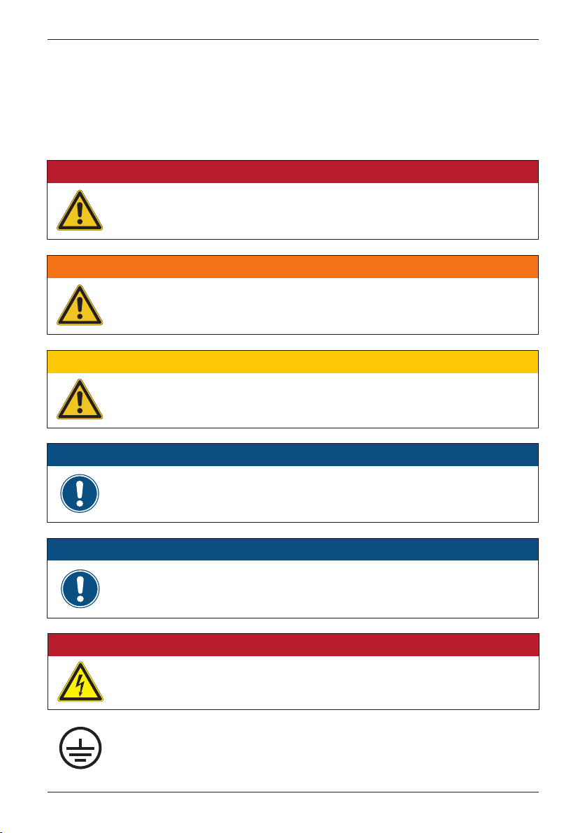
1.2.2 Symbols
This section describes the definition of the symbols in this manual.
In order to prevent both personal injury and property damage, and to ensure
long-term operation of the product, please read this section carefully and follow
all the safety instructions while you use the product.
DANGER!
- This warning indicates an immediate hazard which will lead to death or serious
injury may occur.
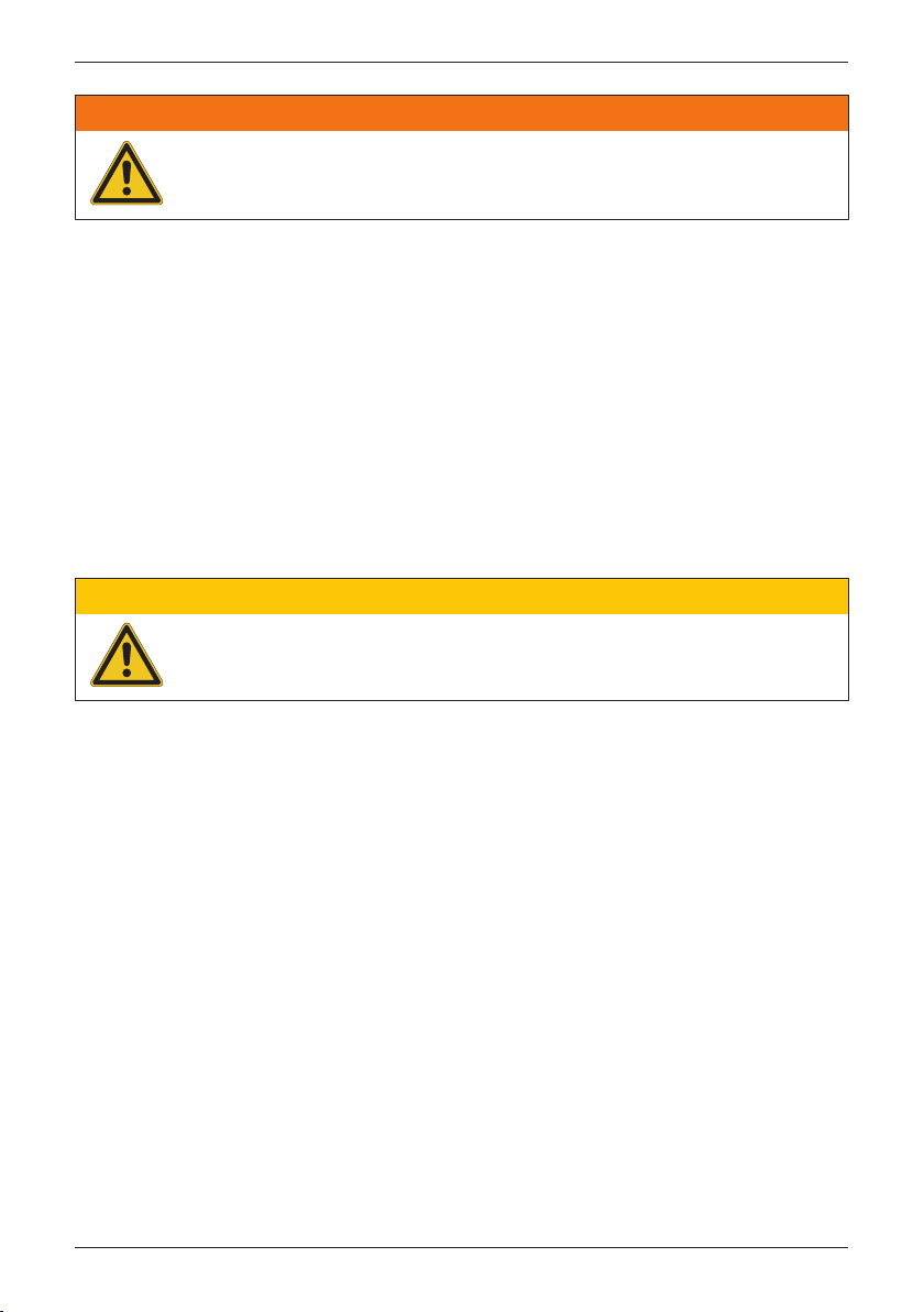
WARNING !
- This warning indicates a possible hazard which may lead to death or serious
injury may occur.
CAUTION !
- This warning indicates a possible hazard which may lead to minor injury
may happen.
Safety
ATTENTION
- This warning indicates a possible damage to property and the environment
might happen.
INFORMATION
- Additional information is indicated by an exclamation mark enclosed by double
circle. This means the following section contains important information and
user should follow the instruction to prevent any hazards.
DANGER : ELECTRICAL HARZARD!!
- This warning indicates an immediate electrical hazard which will lead
to death or serious injury may occur.
- Equipment grounding conductor (PE)
- (PE) Équipement conducteur de terre
7
Page 8

Safety
1.2.3 Safety Instructions
The battery pack should not be installed in direct sunlight or on flammable
surfaces. Please be sure to mount the battery pack tightly on a solid / smooth
surface. The optimal temperature range for the battery pack to operate is 10 to
30℃
. The operating humidity is within the range from 0 to 90%. If the ambient
temperature is outside the operating range, the battery pack stops to protect
itself from any unexpected damage.
This battery pack should be installed by a trained and experienced installer
designated by the retailer. Having the product installed by a non-specialized
installer is very dangerous and can cause damage or injury. The battery pack is
always installed by 2 or more people.
Please make sure any breaker is turned off before connecting cables. Be careful
of the cable length : Must be less than 100 meters.
1.2.3.1 Handling of Prohibitions
The battery module contains flammable materials such as organic solvents.
Mishandling the battery module may cause fire, smoke, or an explosion and the
battery module’s functionality will be seriously damaged. Protection circuits are
designed into the battery pack via BMSS (PCB part inside the battery cabinet)
to protect the battery modules.
Please read and check the following prohibited actions.
8
Page 9

Safety
DANGER!
- This warning indicates an immediate hazard which will lead to death or serious
injury may occur.
(1) Electrical Shock
Do not touch the terminals of the battery module without protectors.
Be grounded with the specified conditions.
High voltage may occur between the positive and the negative terminals.
Electric shock impairs health or may cause threat to life.
More than 2,000 meters higher, risks of an electric shock will be increased.
(2) Immersion
Do not immerse the battery module in liquid such as water, beverages, or
other fluids.
Do not expose to corrosive substances such as sea breeze, steam or chemicals.
Do not install in the humid places or places to condensation.
Exposure to liquid may damage the battery module or the circuit board.
This may cause a battery module's damage to leak electrolyte, generate
heat, smoke, catch fire, or explode.
(3) High Temperature
Do not use or place the battery module near an open flame, heater or high
temperature. Subjecting the battery module to high temperature may damage
the separator and cause internal short circuit.
This may cause the battery module's damage to leak electrolyte, generate heat,
smoke, catch fire, or explode.
(4) Charge Conditions
Only charge the battery module within the specified conditions.
(e.g., temperature range, voltage, current and etc.)
Charging with unspecified conditions (e.g., over charge or abnormal current)
may cause the battery module's damage to leak electrolyte, generate heat,
smoke, catch fire,or explode.
(5) Reverse Polarity
Check the positive (+) and the negative (-) terminals.
If the battery module is connected with a reversed polarity, unexpected
reactions may occur.
This may cause the battery module's damage to leak electrolyte, generate
heat, smoke, catch fire, or explode.
9
Page 10

Safety
(6) Direct Connection
Do not connect the battery module to AC power or unspecified DC power.
This may cause the battery module's damage to leak electrolyte, generate
heat, smoke, catch fire, or explode.
(7) Use in Other Equipment
Do not use the battery module for any other purposes or connecting
unspecified equipment.
If the battery module is used with unapproved applications or systems, the
battery module may be damaged, leak electrolyte, generate heat, smoke,
catch fire, or explode.
(8) Incineration and Heat
Keep the battery module away from heat and fire.
Heating the battery module and may cause it to be damaged, leak electrolyte,
generate heat, smoke, catch fire, or explode.
(9) Short-Circuit
Do not connect between the positive (+) and the negative (-) terminals with
a conductive material (e.g., wire, a cable, etc.).
Do not carry or store the battery module with metal objects.
If the battery module is shorted, the battery module may be overheated.
This may cause the battery module's damage to leak electrolyte, generate
heat, smoke, catch fire, or explode.
(10) Disassembly
Do not disassemble or modify the battery module.
Disassembly or modification of the battery module may damage the
protection circuit.
This may cause the battery module's damage to leak electrolyte, generate
heat, smoke, catch fire, or explode.
(11) Charge in High Temperatures
Do not charge the battery module in high temperature environment.
If the battery module is charged with exposing high temperature, the battery
module’s protection circuit may be activated and stop or fail the charging.
This may cause the battery module's damage to leak electrolyte, generate
heat, smoke, catch fire, or explode.
10
Page 11
Safety
WARNING !
- This warning indicates a possible hazard which may lead to death or serious
injury may occur.
(1) Magnetism
Do not place the battery module near strong magnetism. (e.g., electromagnetic
cooker, etc. )
This may cause the battery module's damage to leak electrolyte, generate
heat, smoke, catch fire, or explode.
(2) Mixed Use
Do not mix with other batteries.
The battery module should not be used with other batteries having a different
capacity, chemistry, manufacturing date or manufacturer.
This could cause the battery module's damage to leak electrolyte, generate
heat, smoke, catch fire, or explode.
CAUTION !
- This warning indicates a possible hazard which may lead to minor injury
may happen.
(1) Exposure to Direct Sunlight
Do not use or leave the battery module in a location exposed to excessive
heat, such as in direct sunlight or in a car. It could cause the battery module's
damage to leak electrolyte, generate heat, smoke, catch fire, or explode.
It may also cause the battery's performance and life to deteriorate.
(2) Charging Temperature Range
Only charge the battery module within operating temperature range.
Charging outside of this temperature range could cause the battery module's
damage to leak electrolyte, generate heat.
It may also cause the battery module's performance and life to deteriorate.
(3) Manual
Please read the system manual or the specfication before use.
Keep the system manual together with this specification for future reference.
(4) Recycling
When disposing of the battery module, recycle it according to local rules
and regulations.
11
Page 12

Introduction
2 Introduction
The DELTA BX_6.0 Battery Pack is designed to enable the highest levels of
efficiency and provide longest operating life of the battery by state-of-the-art
technology. It is suitable for outdoor use.
2.1 Valid Model
The user manual is valid for the following device types :
• DELTA BX_6.0 Battery Pack
This user manual must be followed during installation, operation, and maintenance.
The DELTA BX_6.0 Series have 1 model as shown in Figure 2-2. Delta reserves
the right to make modifications to the content and technical data in this user
manual without prior notice.
12
Page 13

2.2 Product Overview
The shipping components of DELTA BX_6.0 Battery Pack are shown as Figure 2-1.
Figure 2-2 shows the dimensions of DELTA BX_6.0. Figure 2-3 shows the details
of each portion without battery modules.
Introduction
②
①
Figure 2-1 : Shipping Components of DELTA BX_6.0 Battery Pack
BX_6.0
Object Qty Description
1 Delta BX_6.0 1 pc
2 User Manual
3 Mounting Bracket Wall mounting bracket
4 BT Connector 2 sets DC connector for power cable
1 pc
1 set
Battery Pack
Important instructions for Battery Pack
Safety instructions should be followed
during installation and maintenance
③
⑤④
5 RJ45 Connector 1 pc Communication connector
Table 2-1 : Packing list of DELTA BX_6.0 Battery Pack
13
Page 14

Introduction
200 mm
552 mm
596 mm
Figure 2-2 : Dimensions of DELTA BX_6.0 Battery Pack
Lid
BT- BT+
CAN RS-485 Comm.
Standalone Switch
Wall-mounting Bracket
(Two Pieces besides Cabinet)
Figure 2-3 : Overview of DELTA BX_6.0 Battery Pack showing without Battery Module
14
Battery Cabinet
Page 15

Introduction
The following Figure 2-4 shows the rating labels of DELTA BX_6.0 Battery Pack
and the table (Table 2-2) along with these labels explains the definition of the
specific mark.
Figure 2-4 : Rating labels of DELTA BX_6.0 Battery Pack
Symbol Definition
Before working with the Battery Pack, you must read the supplied
manual and follow the instructions contained therein.
The housing of the Battery Pack must be grounded if this is required
by local regulations.
WEEE marking
The Battery Pack must not be disposed of as standard household
waste, but in accordance with the applicable electronic waste
disposal regulations of your country or region.
Table 2-2 : Rating label explanation of DELTA BX_6.0 Battery Pack
15
Page 16

Introduction
2.3 LED Indicators
The DELTA BX_6.0 Battery Pack has three different LED notification colors on
the front cover of the battery pack that signal various system statuses:
LED Status
Flashes red steadily
Stays red
Flashes green steadily
Stays green
Flashes yellow steadily
Stays yellow
Three LED flash steadily
Table 2-3 : LED Indicators
Definition
Warning occurred
Fault occurred
Standby mode
Normal operation mode
Charging
Discharging
Upgrading firmware
Communication failThree LED keep lighting
Figure 2-5 : LED indicators of DELTA BX_6.0 Battery Pack
16
Page 17

3 Installation
WARNING !
- Do not install the battery pack near or on flammable surfaces.
- Please mount the battery pack tightly on a solid / smooth surface.
The chapter contains instructions for (1) Installation environment
(2) Mechanical installation; (3) Electrical Installation; (4) Communication setup.
3.1 Installation Environment
CAUTION !
- The optimal temperature range for the battery pack to operate is 10 to 30℃.
- If the ambient temperature is outside the optimal operating range, the battery
pack will be derating.
- The operating humidity is within the range from 0 to 90%.
- If the ambient temperature is outside the operating range, the battery pack
stops to protect itself from any unexpected damage.
Installation
The battery pack is designed to be waterproof and can be installed both indoors
and outdoors. However, please avoid exposure to direct sunlight, high temperature
and high humidity if installed outdoors.
Please avoid using in the following condition; otherwise the device may malfunction.
• Locations where IP55 isn't satisfied.
• Locations where temperature changes severely.
• Locations where the device is directly exposed to saltwater, sea breezes and
high humidity.
• Locations that are or might be affected by explosive, combustible, corrosive
and other poisonous gases.
• Location exposed dust and dirt.
• Location with poor ventilation.
• Locations with other special conditions.
• At altitude above 2000m.
17
Page 18

Installation
3.2 Mechanical Installation
WARNING !
- This battery pack should be installed by a trained and experienced installer
designated by the retailer.
- Having the product installed by a non-specialized installer is very dangerous
and can cause damage or injury.
CAUTION !
- Please fix at least 6 M8 Phillips head screws for the wall mounting bracket.
- The bracket shipped with the battery pack is specially designed and should be
the only mounting device for the mechanical installation.
- The wall used for mounting should be 90°±2° to or the horizontal reference.
- Make sure there is enough room for the battery pack, especially in front of it.
- Always install the battery pack with 2 or more people.
ATTENTION
- Please make sure that the battery pack stands on the floor when mounting it to
the floor or to a wall.
- Please check the space for installation which meets the recommended location.
- Remember that we will in no way be responsible for damage resulting from the
battery pack falling due to insufficient mounting strength.
This battery pack is designed to be wall-mounted or to stand on the floor fixed.
Please ensure that the installation is perpendicular to the floor.
Please follow the instructions as shown from Figure 3-1 through 3-5.
Please make sure there is enough room for the battery pack, especially in front
of the battery pack (LED indicators).
18
Page 19

100 mm 100 mm
100 mm100 mm100 mm
Figure 3-1 : Recommended Space for Installation
657
617
Installation
437
Φ11
377
317
257
207
Figure 3-2 : Mounting bracket dimensions ( Unit: mm )
19
Page 20

Installation
Necessary for wall-mounting bracket
Figure 3-3 : Required position for at least 6 screws
90°
Figure 3-4 : Permitted mounting positions
CAUTION !
- Please follow the instructions above such as required position for 6 screws and
permitted positions for the correct installation.
20
Page 21

Installation
To mount the battery pack on the wall, please follow the procedure below :
Mount the bracket and the battery pack at the same time.
1. Use 2 screws to fix the bottom part of the mounting bracket.
Drill holes at the locations marked first. Please refer to Figure 3-2 for the
wall mounting bracket dimensions.
2. Hang the battery pack on the wall.
3. Use screws in order to fix rest of the holes as shown in Figure 3-5(a).
Screw the wall mounting bracket on the wall with at least 6 M8 Phillips head
screws are allowable as shown in Figure 3-3.
②
①
③
①
③
Figure 3-5(a) : The procedure for attaching the battery pack on the wall
CAUTION !
- Please fix at least 6 M8 Phillips head screws for the wall mounting bracket.
- The bracket shipped with the battery pack is specially designed and should be
the only mounting device for the mechanical installation.
21
Page 22

Installation
Another way to fix the battery pack is attaching on the floor, please refer to
the following instruction:
Be sure to select the flat floor surface for installation.
Drill 4 holes with 13 mm diameter for each individual hole in order to fix the
battery pack firmly as shown in Figure 3-5(b).
Figure 3-5(b) : Attaching the battery pack on the floor
CAUTION !
- Please do not install the battery pack on uneven floor surfaces.
- Holes size is 13 mm diameter for attaching the battery pack.
22
Page 23

3.3 Electrical Installation for DC(BT+/-)
DANGER : ELECTRICAL HARZARD!!
- Any electric power connected to the battery pack during cabling is prohibited.
- Please make sure any breaker is turned off before connecting cables.
CAUTION : BATTERY DAMAGE MAY OCCUR !
- Please make sure to choose the proper size DC cable.
- Please confirm wire stripping of copper is enough for this DC connector
which seizes the cable firmly.
- Failed to follow the instructions may damage DC cable.
- Please be careful of the cable length:Must be less than 100 meters.
ATTENTION
- This battery pack may be damaged due to moisture or dust intrusion.
Please do not open the lid of the battery pack.
Installation
ATTENTION : UV RESISTANT CABLES ARE RECOMMENDED
- UV resistant cables for DC cables and Ethernet cables (for RJ-45 connector) are
highly recommended.
23
Page 24

Installation
Please read the following instructions for attaching DC terminals :
• It is important to choose the proper size for DC cable.
• DC cable adapter must be assembled as depicted in
• DC connectors are applied to DC Terminals connection as seen in
Figure 3-6.
Figure 3-7.
• It is important to choose the correct DC connectors for positive terminal and
negative terminal. Please refer to
Figure 3-6
and
Figure 3-7.
• Please follow the instructions below to assemble the DC connector.
Please confirm wire stripping of copper is enough for this DC connector which
seizes the cable firmly.
There are two parts of the DC cable adapter.
1. Put the stripped wire into the DC cable adapter
2. Lock it.
3. Attach the bottom part of the DC cable adapter to the upper part of the DC
cable adapter.
4. Rotate and tighten them.
Figure 3-6
depicts the procedure listed above.
ATTENTION
- Please make sure to choose the correct cable for positive terminal and
negative terminal.
- Please note that male connectors are for positive terminals on both sides of
the cable.
24
Page 25

18mm
Figure 3-6 : Assemble the DC Connector
BT Status Current Rating Wire Size
Charge DC 30A
Discharge DC 35A
Table 3-1 : Maximum Current Ratings for Power Cables
6 - 16 mm
(10 - 6 AWG)
Installation
2
BT- BT+
CAN RS-485 Comm.
Standalone Switch
Figure 3-7 : Connectors on Cabinet (Zooming from Figure 2-3 )
25
Page 26

Installation
3.4 CAN and RS-485 Communication Connection
The following figure shows communication location of DELTA BX_6.0 Battery
Pack on one side of the battery cabinet. The table describes the CAN and
RS-485 communication definition of the port. Please note that DC connector
at both sides of the battery cabinet have the same function. User can either
plug-in DC cables from left side or right side of the cabinet. Please refer to
Figure 3-7.
1
2
3
4
5
6
7
Definition
VCC
GND
GND
CAN‐High
CAN‐Low
N/A
485A
485B8
PIN
Table 3-2 : Communication Definition of DELTA BX_6.0 Battery Pack
The following figure describes the assembly instructions for installing the RJ-45
connector on the cabinet. Figure 3-8 shows each parts in detail.
Figure 3-8 : Overview of Communication Connectors
26
Page 27

Installation
The following instructions demonstrates the assembly procedure:
RJ-45 cable without cable connector boots plug cover (soft plastic) is recommended
as indicated in Figure 3-9.
1. Insert the sealing nut, seals, and support into the cable assembly.
(Cable OD range: 5.0 ~ 6.5 mm.)
2. Connect the sealing nut on the half-finished goods and screw tightly.
(Sealing nut torsion value range: 5~15 kgf-cm)
Please refer to Figure 3-10 for details.
Figure 3-9: Suitable cables for RJ45 connector
Figure 3-10 : Installing Procedure of Communication Connectors on the Cabinet
27
Page 28

Commissioning via Standalone Operation
4
Commissioning via Standalone Operation
The standalone switch on the right side of the
It can wake up the battery modules when there is no utility grid.
This battery pack may be useful due to backup electricity supply.
It charges power electricity generated from solar panel and discharges electricity
during power outages in the evening.
The battery pack offers standalone operation for inverter and safer emergency
backup.
Please note that, you should hold the button for 5 seconds to activate the
standalone function.
Figure 3-7 .
28
Page 29

5 Battery Pack Expansion
WARNING !
- Before expanding the extra battery pack, please switch the battery pack power
off to avoid risk of electrical shock.
- Please check the battery pack regularly. If there are any impaired or loose parts,
please contact your installer. Ensure that there are no fallen objects.
The battery pack expansion is shown in Figure 5-1. At most one extra battery
pack can be added. Please make sure the positive cable is connected to positive
terminal at both sides.
Battery Pack Expansion
Figure 5-1 : Expanding the Battery Pack with DC(BT+/-) cables and Ethernet cable (See Section 3.3 and 3.4)
29
Page 30

Trouble Shooting
6 Trouble Shooting
Check LED notification on the front cover of the battery pack which indicates
various system statuses. The following table describes the possible causes of
LED indicators and the ways to repair the battery pack.
DELTA BX_6.0 Battery Pack LED Indicators
LED Status Possible Cause Repair Methods
Flashes red
steadily
(Warning)
Stays Red
(Fault)
Three LED
keep
lighting
SOH < 50%
Over Voltage Protection
Under Voltage Protection
Over Temperature Protection
Under Temperature Protection
Over Charge Current Protection
Over Discharge Current Protection
Communication fail
Table 6-1 : Trouble shootings for DELTA BX_6.0
Contact your distributor /
our customer service for technical support
Battery pack replacement is recommended.
1. Check voltage on inverter side
2. Check if ambient temperature is out of
operating range
3. Check current on inverter side
4. Contact your distributor /
our customer service for technical support
1. Check the CAN communication
2. Contact your distributor /
our customer service for technical support
30
Page 31

Technical Data
7 Technical Data
Model
General
Protection degree
Dimension (W x H x D, mm)
Weight (kg)
Pollution degree III
Operating altitude 0 to 2000m (0 to 6666 ft.)
Electrical Rating
Capacity
Nominal Voltage
Maximum Charge Current
Nominal Charge Voltage
Maximum Discharge Current
Available Operating Temperature
Optimal Operating Temperature
Ambient Storage Conditions
Humidity
End of Life
Interface
Cable
External Communication
Cooling
Regulations & Certifications
CE Conformity IEC 62040 - 1 IEC 62109 - 1/ - 2
UN transportation testing requirements UN 3480 Section 38.3 (module)
Safety
EMC
CAN and RS‐485 (8 Pins)
IEC 61000 - 6 -3
IEC 61000 - 3 -12
IEC 61000 - 4 -3
IEC 61000 - 4 -5
IEC 61000 - 4 -8
BX_6.0
IP55
552 x 596 x 200
75
6 kWh
93.6 V
30.0 A
104.0 V
35.0 A
-10~45 ℃
10 ~30 ℃
-20 ~50 ℃
0 ~ 90 %
SOH 50 %
2
6 - 16mm
(10 - 6AWG)
Natural Convection
IEC 61000 - 3 -11
IEC 61000 - 4 -2
IEC 61000 - 4 -4
IEC 61000 - 4 -6
IEC 61000 - 4 -11
Table 7-1 : Specifications for DELTA BX_6.0
31
Page 32

Page 33

Page 34

Page 35

Page 36

5013245001
Version 1.02 | 2016 | Oct.
 Loading...