

Page 1
10"BandSaw
Scie_rubande
254mm(10po)
Sierradebanda
54mm(10po)
A15113-01-13-06Rev.A
Copyright© 2006DeltaMachinery
InstructionManual
Manueld'Utilisation
ManualdeInstrucciones
www.deltamachinery.com
(800)223-7278- US
(800)463-3582- CANADA
Page 2

IMPORTANT SAFETY INSTRUCTIONS ........................................................... 2
SAFETY GUIDELINES = DEFiNITiONS ........................................................... 3
GENERAL SAFETY RULES .................................................................... 4
ADDITIONAL SPECIFIC SAFETY RULES ......................................................... 5
FUNCTIONAL DESCRIPTION .................................................................. 7
CARTON CONTENTS ......................................................................... 7
ASSEMBLY ................................................................................. 8
OPERATION ............................................................................... 12
TROUBLESHOOTING GUIDE .................................................................. 20
TROUBLESHOOTING ........................................................................ 22
MAINTENANCE ............................................................................. 23
SERVICE .................................................................................. 23
ACCESSORIES ............................................................................. 23
WARRANTY ................................................................................ 24
FRAN_AIS ................................................................................. 25
ESPA_IOL .................................................................................. 47
Read and understand all warnings and operating instructions before using any tool or equipment.
When using tools or equipment, basic safety precautions should always be followed to reduce the risk of
personal injury. Improper operation, maintenance or modification of tools or equipment could result in serious
injury and property damage. There are certain applications for which tools and equipment are designed. Delta
Machinery strongly recommends that this product NOT be modified and/or used for any application other than
for which it was designed.
if you have any questions relative to its application DO NOT use the product until you have written Delta Machinery
and we have advised you.
Online contact form at www.deltamachinery.com
Postal Mail: Technical Service Manager
Delta Machinery
4825 Highway 45 North
Jackson, TN 38305
(IN CANADA: 125 Mural St. Suite 300, Richmond Hill, ON, L4B 1M4)
Information regarding the safe and proper operation of this tool isavailable from the following sources:
Power Tool Institute
1300 Sumner Avenue, Cleveland, OH 44115-2851
www.powertoolinstitute.org
National Safety Council
1121 Spring Lake Drive, Itasca, IL60143-3201
American National Standards Institute, 25 West 43rd Street, 4 floor, New York, NY 10036 www.ansi.org
ANSi 01.1Safety Requirements for Woodworking Machines, and the U.S. Department of Labor regulations www.osha.g£y
SAVE THESE INSTRUCTIONS!
Page 3

it is important for you to read and understand this manual. The information it contains relates to
protecting YOUR SAFETY and PREVENTING PROBLEMS. The symbols below are used to help you _Q_
recognize this information.
indicates an imminently hazardous situation which, if not avoided, will result in death or
_ serious injury.
__,dL
-- injury.
-- injury.
-- avoided, may result inproperty damage.
CALiFORNiA PROPOSiTiON 65
SOME DUST CREATED BY POWER SANDING, SAWING, GRINDING, DRILLING, AND OTHER CONSTRUCTION
ACTIVITIES contains chemicals known to cause cancer, birth defects or other reproductive harm. Some examples of
these chemicals are:
• lead from lead-based paints,
•crystalline silica from bricks and cement and other masonry products, and
• arsenic and chromium from chemically-treated lumber•
Your risk from these exposures varies, depending on how often you do this type of work. To reduce your exposure to
these chemicals: work in a well ventilated area, and work with approved safety equipment, always wear NIOSH/OSHA
approved, properly fitting face mask or respirator when using such tools.
Indicates a potentially hazardous situation which, if not avoided, could result in death or serious
indicates a potentially hazardous situation which, if not avoided, may result in minor or moderate
Used without the safety alert symbol indicates potentially hazardous situation which, if not
Page 4

Failure to follow these rules may result in serious personal injury.
1. FOR YOUR OWN SAFETY, READ THE INSTRUCTION
MANUAL BEFORE OPERATING THE MACHINE. Learning
the machine's application, limitations, and specific hazards
will greatly minimize the possibility of accidents and injury.
2. WEAR EYE AND HEARING PROTECTION. ALWAYS
USE SAFETY GLASSES. Everyday eyeglasses are NOT
safety glasses. USE CERTIFIED SAFETY EQUIPMENT.
Eye protection equipment should comply with ANSI Z87.1
standards. Hearing equipment should comply with ANSI
$3.19 standards.
3. WEAR PROPER APPAREL, Do not wear loose clothing,
gloves, neckties, rings, bracelets, or other jewelry which may
get caught in moving parts. Nonslip protective footwear is
recommended. Wear protective hair covering to contain long
hair.
4. DO NOT USE THE MACHINE IN A DANGEROUS
ENVIRONMENT. The use of power tools in damp or wet
locations or in rain can cause shock or electrocution. Keep
your work area well-lit to prevent tripping or placing arms,
hands, and fingers in danger.
5. MAINTAIN ALL TOOLS AND MACHINES IN PEAK
CONDiTiON, Keep tools sharp and clean for best and safest
performance. Follow instructions for lubricating and changing
accessories. Poorly maintained tools and machines can further
damage the tool or machine and/or cause injury.
6. CHECK FOR DAMAGED PARTS. Before using the machine,
check for any damaged parts. Check for alignment of moving
parts, binding of moving parts, breakage of parts, and any
other conditions that may affect its operation. A guard or any
other part that is damaged should be properly repaired or
replaced with Delta or factory authorized replacement
parts. Damaged parts can cause further damage to the
machine and/or injury.
7. KEEP THE WORK AREA CLEAN. Cluttered areas and benches
inviteaccidents.
8. KEEP CHILDREN AND VISITORS AWAY. Your shop is a
potentially dangerous environment. Children and visitors can be
injured.
9. REDUCE THE RISK OF UNINTENTIONAL STARTING. Make
sure that the switch is in the "OFF" position before plugging
in the power cord. In the event of a power failure, move the
switch to the "OFF" position. An accidental start-up can cause
injury. Do not touch the plug's metal prongs when unplugging
or plugging in the cord.
10. USE THE GUARDS. Check to see that all guards are in place,
secured, and working correctly to prevent injury.
11. REMOVE ADJUSTING KEYS AND WRENCHES BEFORE
STARTING THE MACHINE. Tools, scrap pieces, and other
debris can be thrown at high speed, causing injury.
12. USE THE RIGHT MACHINE. Don't force a machine or an
attachment to do a job for which it was not designed. Damage
to the machine and/or injury may result.
13. USE RECOMMENDED ACCESSORIES. The use of
accessories and attachments not recommended by Delta
may cause damage to the machine or injury to the user.
14. USE THE PROPER EXTENSION CORD. Make sure your
extension cord is in good condition. When using an extension
cord, be sure to use one heaw enough to carry the current
your product will draw. An undersized cord will cause a drop
in line voltage, resulting in loss of power and overheating. See
the Extension Cord Chart for the correct size depending on
the cord length and nameplate ampere rating. If in doubt, use
the next heavier gauge. The smaller the gauge number, the
heavier the cord.
15. SECURE THE WORKPIECE. Use clamps or a vise to hold the
workpiece when practical. Loss of control of aworkpiece can
cause injury.
16. FEED THE WORKPIECE AGAINST THE DiRECTiON OF
THE ROTATION OF THE BLADE, CUTTER, OR ABRASIVE
SURFACE. Feeding it from the other direction will cause the
workpiece to be thrown out at high speed.
17. DON'T FORCE THE WORKPIECE ON THE MACHINE.
Damage to the machine and/or injury may result.
18. DON'T OVERREACH. Loss of balance can make you fall into
a working machine, causing injury.
19. NEVER STAND ON THE MACHINE. Injurycould occur ifthe tool
tips,or ifyou accidentally contact the cuttingtool.
20. NEVER LEAVE THE MACHINE RUNNING UNATTENDED.
TURN THE POWER OFE Don't leavethe machine until it comes
to acomplete stop. A child or visitor couldbe injured.
21. TURN THE MACHINE "OFF", AND DISCONNECT THE
MACHINE FROM THE POWER SOURCE before installing or
removing accessories, changing cutters, adjusting or changing
set-ups. When making repairs, be sure to lock the start switch
in the "OFF" position. An accidental start-up can cause injury.
22. MAKE YOUR WORKSHOP CHILDPROOF WiTH
PADLOCKS, MASTER SWITCHES, OR BY REMOVING
STARTER KEYS. The accidental start-up of a machine by a
child or visitor could cause injury.
23. STAY ALERT, WATCH WHAT YOU ARE DOING, AND USE
COMMON SENSE. DO NOT USE THE MACHINE WHEN
YOU ARE TIRED OR UNDER THE iNFLUENCE OF DRUGS,
ALCOHOL, OR MEDICATION. A moment of inattention while
operating power tools may result in injury.
24. _ USE OF THIS TOOL CAN GENERATE AND
DISBURSE DUST OR OTHER AIRBORNE PARTICLES,
iNCLUDiNG WOOD DUST, CRYSTALLINE SiLiCA DUST
AND ASBESTOS DUST. Direct particles away from face
and body. Always operate tool in well ventilated area and
provide for proper dust removal. Use dust collection system
wherever possible. Exposure to the dust may cause serious
and permanent respiratory or other injury, including silicosis (a
serious lung disease), cancer, and death. Avoid breathing the
dust, and avoid prolonged contact with dust. Allowing dust to
get into your mouth or eyes, or lay on your skin may promote
absorption of harmful material. Always use properly fitting
NIOSH/OSHA approved respiratory protection appropriate for
the dust exposure, and wash exposed areas with soap and
water.
Page 5

Failure to follow these rules may result in serious personal injury.
1. DO NOT OPERATE THiS MACHINE UNTIL it is
assembled and installed according to the instruc-
tions.
2. OBTAIN ADVICE from your supervisor, instructor,
or another qualified person if you are not familiar
with the operation of this tool.
3. FOLLOW ALL WiRiNG CODES and recommended
electrical connections.
4. USETHE GUARDSWHENEVER POSSIBLE. Checkto
see that they are in place, properly adjusted, secured,
and working correctly.
5. USE PROPER BLADE SiZE and type.
6. ADJUST THE UPPER BLADE GUIDE so that it is
about 1/8" above the workpiece.
7. PROPERLY ADJUST the blade tension, tracking,
blade guides, and blade support bearings.
8. KEEP ARMS, HANDS, AND FINGERS away from
the blade.
9. AVOID AWKWARD OPERATIONS and hand po-
sitions where a sudden slip could cause a hand to
move into the blade.
10. NEVER START THE MACHINE before clearing the
table of all objects (tools, scrap pieces, etc.).
11. NEVER START THE MACHINE with the workpiece
against the blade.
12. HOLD WORKPIECE FIRMLY against the table. DO
NOT attempt to saw a workpiece that does not have
a flat surface against the table.
13. HOLD WORKPIECE FIRMLY and feed into blade at
a moderate speed.
14. NEVER REACH UNDER THE TABLE while the ma-
chine is running.
15. TURN THE MACHINE "OFF" to back out of an un-
completed or jammed cut.
16. MAKE "RELIEF" CUTS prior to cutting long curves.
17. TURN THE MACHINE "OFF" and wait for the blade
to stop prior to cleaning the blade area, removing
debris near the blade, removing or securing work-
piece, or changing the angle of the table. A coasting
blade can be dangerous.
18. NEVER PERFORM LAYOUT, ASSEMBLY, or set-
up work on the table/work area when the machine is
running.
19. TURN THE MACHINE "OFF" AND DISCONNECT
THE MACHINE from the power source before in-
stalling or removing accessories, before adjusting or
changing set-ups, or when making repairs.
20. TURN THE MACHINE "OFF", disconnect the ma-
chine from the power source, and clean the table/
work area before leaving the machine. LOCK THE
SWITCH iN THE "OFF" POSiTiON to prevent unau-
thorized use.
21.
ADDITIONAL INFORMATION regarding the safe
and proper operation of power tools (i.e. a safety
video) isavailable from the Power Tool Institute, 1300
Sumner Avenue, Cleveland, OH 44115-2851 (www.
powertoolinstitute.com). Information is also avail-
able from the National Safety Council, 1121 Spring
Lake Drive, Itasca, IL 60143-3201. Please refer to
the American National Standards Institute ANSI 01.1
Safety Requirements for Woodworking Machines
and the U.S. Department of Labor OSHA 1910.213
Regulations.
THESE iNSTRUCTiONS.
Refer to them often and use them to instruct others.
POWER CONNECTIONS
A separate electrical circuit should be used for your machines. This circuit should not be less than #12 wire and should
be protected with a 20 Amp time lag fuse. If an extension cord is used, use only 3-wire extension cords which have
3-prong grounding type plugs and matching receptacle which will accept the machine's plug. Before connecting the
machine to the power line, make sure the switch (s) is in the "OFF" position and be sure that the electric current is of
the same characteristics as indicated on the machine. All line connections should make good contact. Running on low
voltage will damage the machine.
DO NOT EXPOSE THE MACHINE TO RAIN OR OPERATE THE MACHINE IN DAMP LOCATIONS.
MOTOR SPECiFiCATiONS
Your machine is wired for 120 volt, 60 HZ alternating current. Before connecting the machine to the power source,
make sure the switch is inthe "OFF" position.
Page 6
GROUNDING iNSTRUCTiONS
This machine must be grounded while in use to protect the operator from electric shock.
1. All grounded, cord-connected machines:
In the event of a malfunction or breakdown, grounding provides a path of least resistance for electric current to
reduce the risk of electric shock. This machine is equipped with an electric cord having an equipment-grounding
conductor and a grounding plug. The plug must be plugged into a matching outlet that is properly installed and
grounded in accordance with all local codes and ordinances.
Do not modify the plug provided - if it will not fit the outlet, have the proper outlet installed by a qualified electrician.
Improper connection of the equipment-grounding conduc-tor can result in risk of electric shock. The conductor
with insulation having an outer surface that is green with or without yellow stripes is the equipment-grounding
conductor. If repair or replacement of the electric cord or plug is necessary, do not connect the equipment-
grounding conductor to a live terminal.
Check with a qualified electrician or service personnel if the grounding instructions are not completely
understood, or if in doubt as to whether the machine is properly grounded.
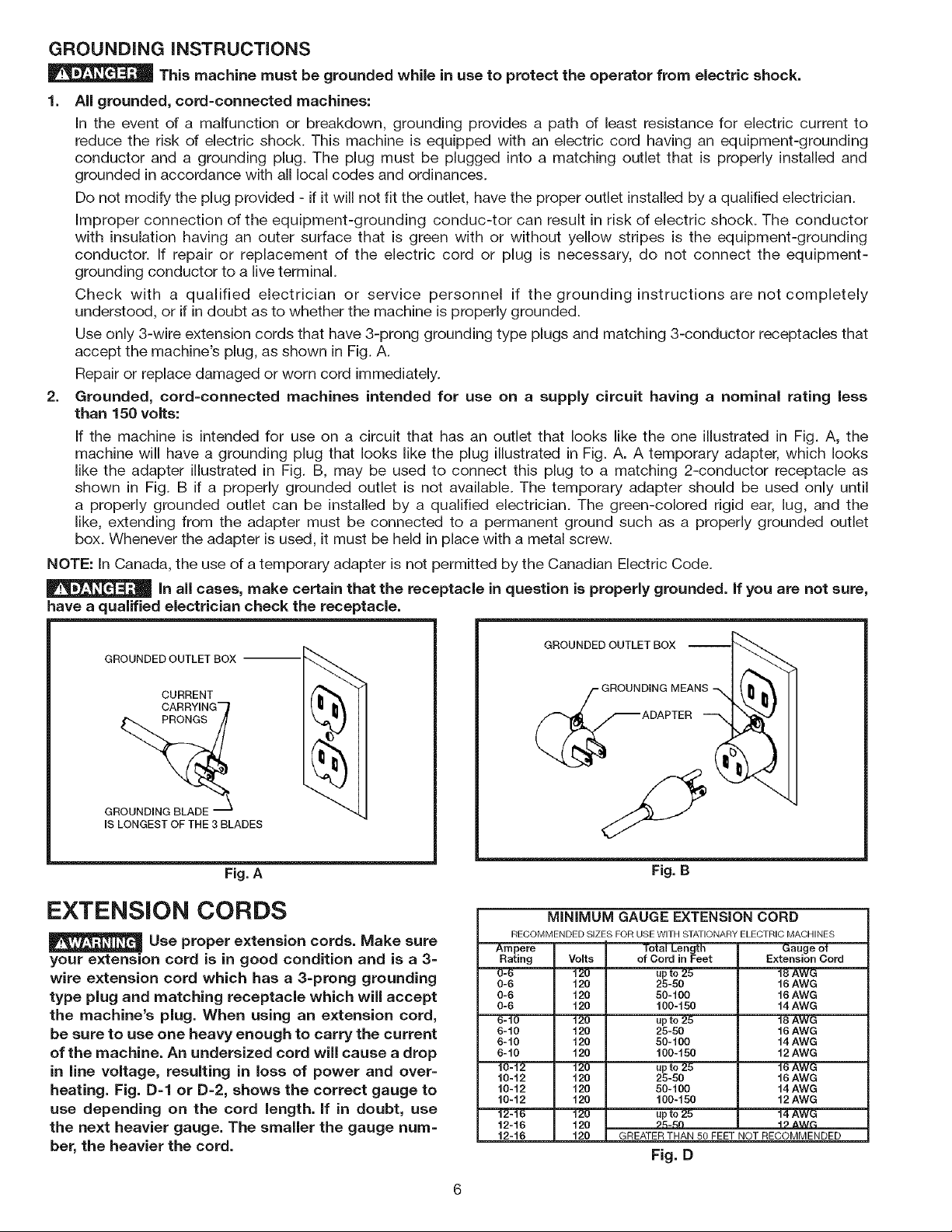
Use only 3-wire extension cords that have 3-prong grounding type plugs and matching 3-conductor receptacles that
accept the machine's plug, as shown in Fig. A.
Repair or replace damaged or worn cord immediately.
2. Grounded, cord-connected machines intended for use on a supply circuit having a nominal rating less
than 150 volts:
If the machine is intended for use on a circuit that has an outlet that looks like the one illustrated in Fig. A, the
machine will have a grounding plug that looks like the plug illustrated in Fig. A. A temporary adapter, which looks
like the adapter illustrated in Fig. B, may be used to connect this plug to a matching 2-conductor receptacle as
shown in Fig. B if a properly grounded outlet is not available. The temporary adapter should be used only until
a properly grounded outlet can be installed by a qualified electrician. The green-colored rigid ear, lug, and the
like, extending from the adapter must be connected to a permanent ground such as a properly grounded outlet
box. Whenever the adapter is used, it must be held in place with a metal screw.
NOTE: In Canada, the use of a temporary adapter is not permitted by the Canadian Electric Code.
In all cases, make certain that the receptacle in question is properly grounded. If you are not sure,
have a qualified electrician check the receptacle.
GROUNDED OUTLET BOX
CURRENT
CAR RYIN G"-_
GROUNDING BLADE
IS LONGEST OF THE 3 BLADES
Fig. A
EXTENSION CORDS
Use proper extension cords. Make sure
your extension cord is in good condition and is a 3=
wire extension cord which has a 3=prong grounding
type plug and matching receptacle which will accept
the machine's plug. When using an extension cord,
be sure to use one heavy enough to carry the current
of the machine. An undersized cord will cause a drop
in line voltage, resulting in loss of power and over=
heating. Fig. D=I or D=2, shows the correct gauge to
use depending on the cord length, if in doubt, use
the next heavier gauge. The smaller the gauge num-
ber, the heavier the cord.
GROUNDED OUTLET BOX
MEAN
Fig. B
MiNiMUM GAUGE EXTENSION CORD
RECOMMENDED SIZES FOR USE WITH STATIONARY ELECTRIC MACHINES
Ampere Total Length
Rating Volts of Cord JnFeet
0-6 120 up to 25
0-6 120 25-50
0-6 120 50-100
0-6 120 100-150
6-10 120 up to 25
6-10 120 25-50
6-10 120 50-100
6-10 120 100-150
10-12 120 up to 25
10-12 120 25-50
10-12 120 50-100
10-12 120 100-150
12-16 120 up to 25
12-16 120 _._n
12-16 120
GREATER THAN 50 FEET NOT RECOMMENDED
Gauge of
Extension Cord
18 AWG
16 AWG
16 AWG
14 AWG
18 AWG
16 AWG
14 AWG
12 AWG
16 AWG
16 AWG
14 AWG
12 AWG
14 AWG
4_ AW_
Fig. D
Page 7
FOREWORD
The Delta Model BS150LS 10" Band Saw has a powerful 1/2 HE ball-bearing motor for smooth performance and long
life. The saw has a 7 inch depth of cut capacity. The BS150LS is supplied with a cast iron table and sturdy steel stand
which provides heavy-duty support and a comfortable work height.
NOTICE: The photo on the manual cover illustrates the current production model. All other illustrations contained in the
manual are representative only and may not depict the actual labeling or accessories included. These are intended to
illustrate technique only.
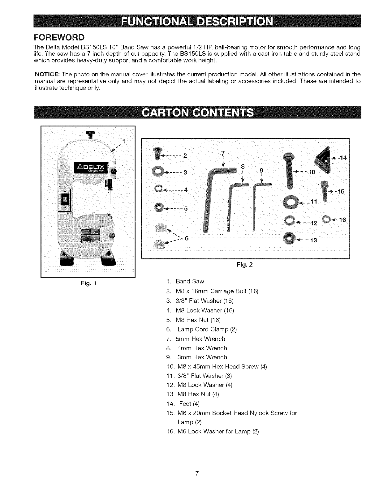
Fig. 1
....
7
I
Fig. 2
1. Band Saw
2. M8 x 16mm Carriage Bolt (16)
3. 3/8" Flat Washer (16)
4. M8 Lock Washer (16)
5. M8 Hex Nut (16)
6. Lamp Cord Clamp (2)
7. 5mm Hex Wrench
8. 4mm Hex Wrench
9. 3mm Hex Wrench
10. M8 x 45mm Hex Head Screw (4)
11. 3/8" Flat Washer (8)
12. M8 Lock Washer (4)
13. M8 Hex Nut (4)
14. Feet (4)
15. M6 x 20mm Socket Head Nylock Screw for
Lamp (2)
16. M6 Lock Washer for Lamp (2)
Page 8
UNPACKING AND CLEANING
Carefully unpack the machine and all loose items from the shipping container(s). Remove the rust-preventative oil from
unpainted surfaces using a soft cloth moistened with mineral spirits, paint thinner or denatured alcohol.
Do not use highly volatile solventssuch as gasoline, naphtha, acetone or lacquer thinner for cleaning your
machine.
After cleaning, cover the unpainted surfaces with a good quality household floor paste wax.
For your own safety, do not connect the machine to the power source until the machine is
completely assembled and you read and understand the entire instruction manual
ASSEMBLY TOOLS REQUIRED
1. 3mm Hex Wrench - provided
2. 4mm Hex Wrench - provided
3. 5mm Hex Wrench - provided
4. M8 Socket - not provided
5. M8 Wrench - not provided
ASSEMBLY TIME ESTIMATE
Assembly for this machine takes approximately 2 to 3 hours.
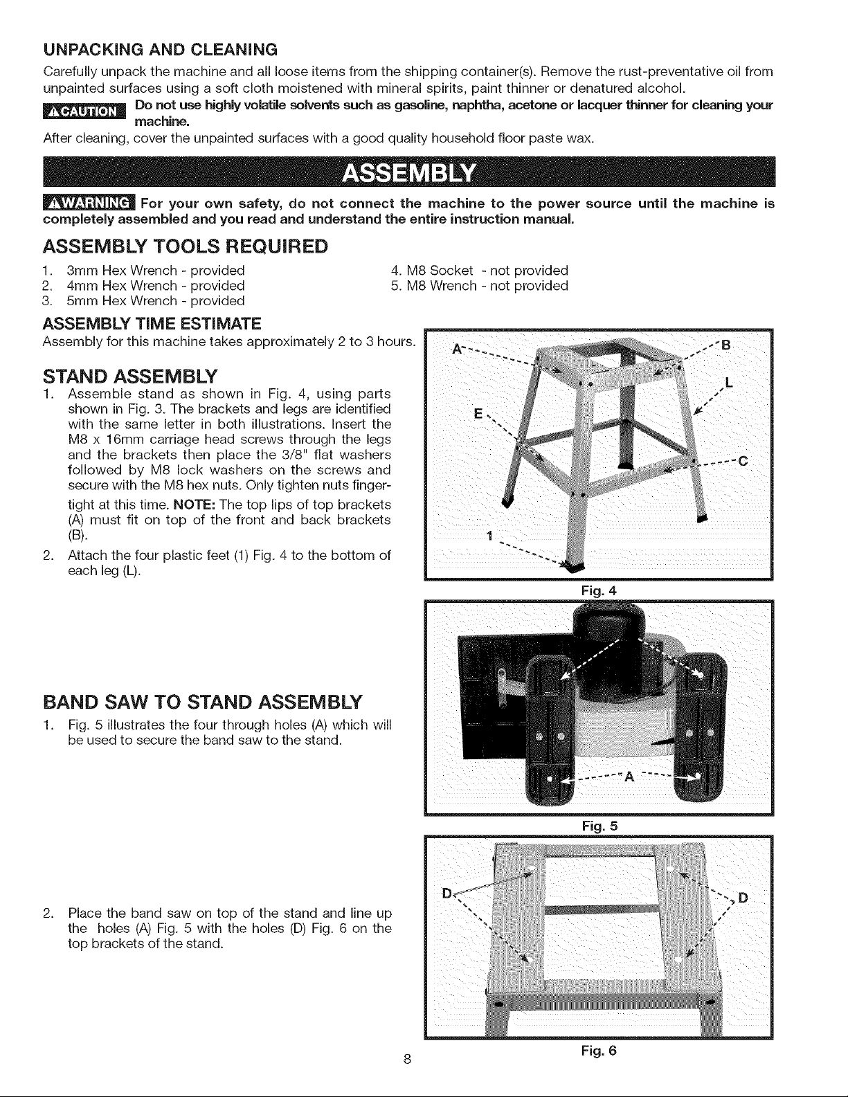
STAND ASSEMBLY
1. Assemble stand as shown in Fig. 4, using parts
shown in Fig. 3. The brackets and legs are identified
with the same letter in both illustrations. Insert the
M8 x 16mm carriage head screws through the legs
and the brackets then place the 3/8" flat washers
followed by M8 lock washers on the screws and
secure with the M8 hex nuts. Only tighten nuts finger-
tight at this time. NOTE: The top lips of top brackets
(A) must fit on top of the front and back brackets
(B).
2. Attach the four plastic feet (1) Fig. 4 to the bottom of
each leg (L).
Fig. 4
BAND SAW TO STAND ASSEMBLY
1. Fig. 5 illustrates the four through holes (A) which will
be used to secure the band saw to the stand.
2_
Place the band saw on top of the stand and line up
topthebracketsh°les(A)ofFig.the5stand.withthe holes (D)Fig. 6 on the
Fig. 5
8 Fig. 6
Page 9
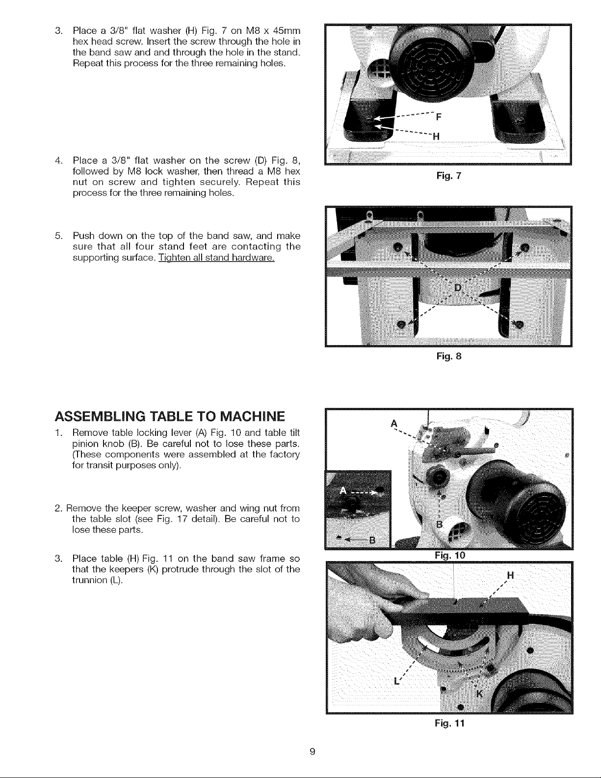
3.
Place a 3/8" flat washer (H) Fig, 7 on M8 x 45mm
hex head screw. Insert the screw through the hole in
the band saw and and through the hole in the stand.
Repeat this process for the three remaining holes.
.
Place a 3/8" flat washer on the screw (D) Fig. 8,
followed by M8 lock washer, then thread a M8 hex
nut on screw and tighten securely. Repeat this
process for the three remaining holes.
5. Push down on the top of the band saw, and make
sure that all four stand feet are contacting the
supporting surface. Tighten all stand hardware.
Fig. 7
ASSEMBLING TABLE TO MACHINE
1.
Remove table locking lever (A) Fig. 10 and table tilt
pinion knob (B). Be careful not to lose these parts.
(These components were assembled at the factory
for transit purposes only).
2. Remove the keeper screw, washer and wing nut from
the table slot (see Fig. 17 detail). Be careful not to
lose these parts.
3. Place table (H) Fig. 11 on the band saw frame so
that the keepers (K) protrude through the slot of the
trunnion (L).
Fig. 8
Fig. 10
Fig. 11
Page 10
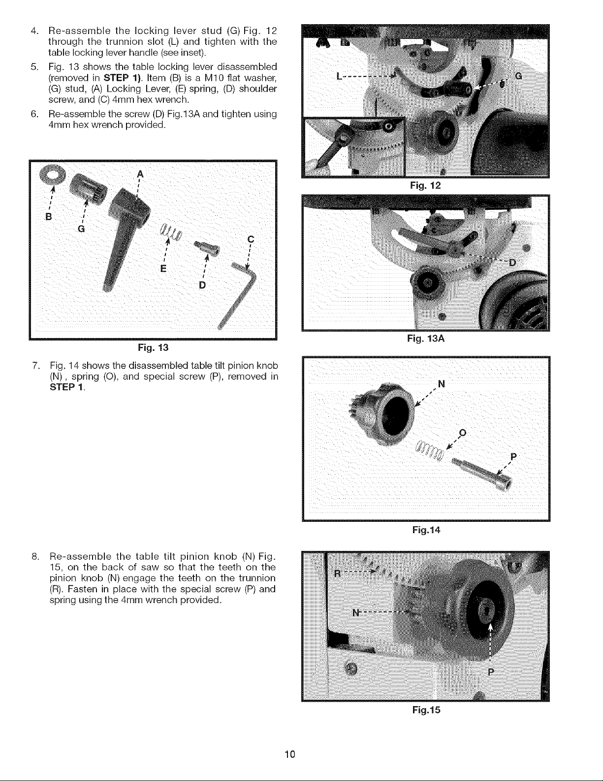
4. Re-assemblethe lockingleverstud (G)Fig. 12
throughthe trunnionslot (L)andtightenwiththe
tablelockingleverhandle(seeinset).
5. Fig.13showsthetablelockingleverdisassembled
(removedinSTEP1).Item(B)isa M10flatwasher,
(G)stud,(A)LockingLever,(E)spring,(D)shoulder
screw,and(C)4mmhexwrench.
6. Re-assemblethescrew(D)Fig.13Aandtightenusing
4mmhexwrenchprovided.
Fig. 12
Fig. 13
7.
Fig. 14 shows the disassembled table tilt pinion knob
(N), spring (O), and special screw (P), removed in
STEP 1.
8.
Re-assemble the table tilt pinion knob (N) Fig.
15, on the back of saw so that the teeth on the
pinion knob (N) engage the teeth on the trunnion
(R). Fasten in place with the special screw (P) and
spring using the 4mm wrench provided.
Fig. 13A
N
Fig.14
10
Fig.15
Page 11
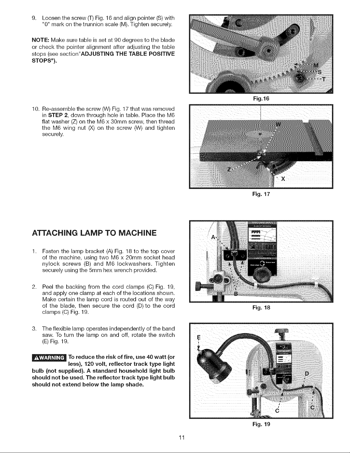
9. Loosenthescrew(T)Fig.16andalignpointer(S)with
"0"markonthetrunnionscale(M).Tightensecurely.
NOTE:Makesuretableissetat90degreestotheblade
orcheckthepointeralignmentafteradjustingthetable
stops(seesection"ADJUSTINGTHE TABLE POSiTiVE
STOPS").
10. Re-assemble the screw (W) Fig. 17 that was removed
in STEP 2, down through hole in table. Place the M6
flat washer (Z) on the M6 x 30mm screw, then thread
the M6 wing nut (X) on the screw (W) and tighten
securely.
Fig.16
ATTACHING LAMP TO MACHINE
1.
Fasten the lamp bracket (A) Fig. 18 to the top cover
of the machine, using two M6 x 20mm socket head
nylock screws (B) and M6 Iockwashers. Tighten
securely using the 5mm hex wrench provided.
2.
Peel the backing from the cord clamps (C) Fig. 19,
and apply one clamp at each of the locations shown.
Make certain the lamp cord is routed out of the way
of the blade, then secure the cord (D)to the cord
clamps (C) Fig. 19.
3. The flexible lamp operates independently of the band
saw. To turn the lamp on and off, rotate the switch
(E) Fig. 19.
To reduce the risk of fire, use 40 watt (or
less), 120 volt, reflector track type light
bulb (not supplied). A standard household light bulb
should not be used. The reflector track type light bulb
should not extend below the lamp shade.
Fig. 17
Fig. 18
11
Fig. 19
Page 12
IOPERATIONAL CONTROLS AND ADJUSTMENTS I
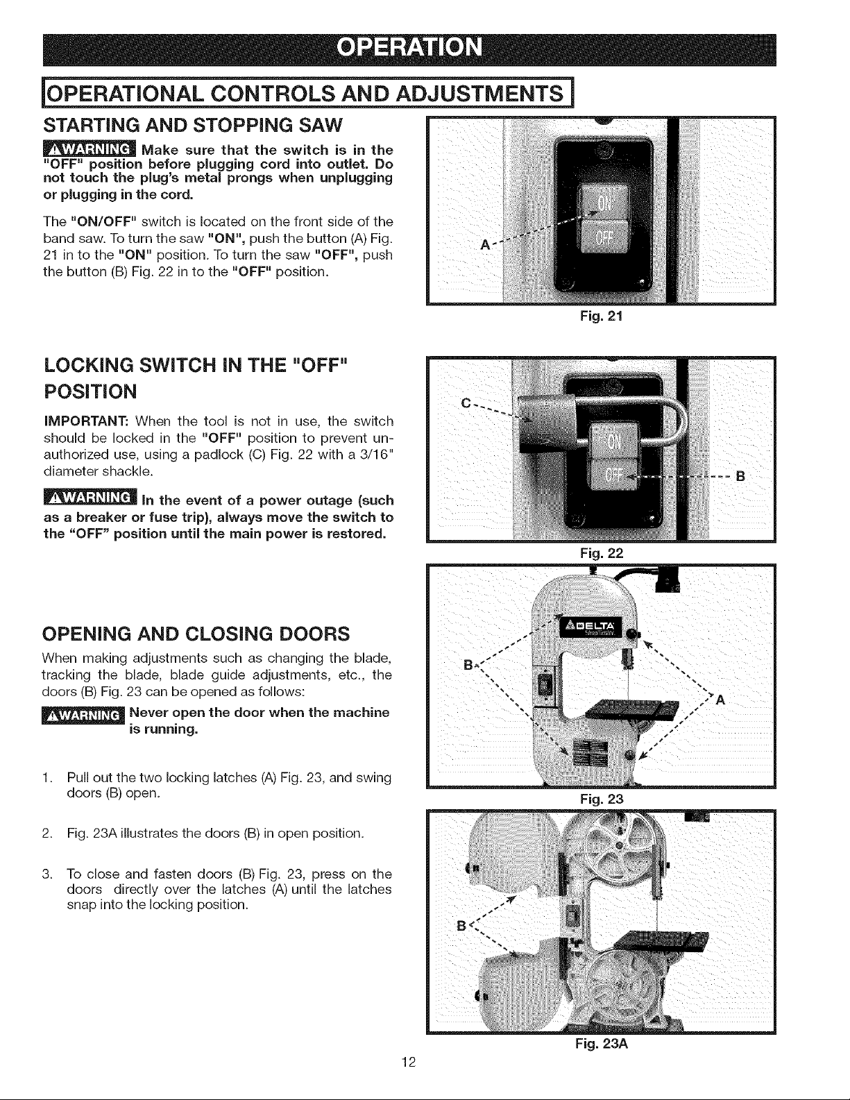
STARTING AND STOPPING SAW
Make sure that the switch is in the
"OFF" position before plugging cord into outlet. Do
nottouchtheplug'smetalprongswhenunplugging
or plugging in the cord.
The "ON/OFF" switch is located on the front side of the
band saw. To turn the saw "ON", push the button (A) Fig.
21 in to the "ON" position. To turn the saw "OFF", push
the button (B) Fig. 22 in to the "OFF" position.
LOCKING SWITCH IN THE "OFF"
POSITION
IMPORTANT: When the tool is not in use, the switch
should be locked in the "OFF" position to prevent un-
authorized use, using a padlock (C) Fig. 22 with a 3/16"
diameter shackle.
Fig. 21
in the event of a power outage (such
as a breaker or fuse trip}, always move the switch to
the "OFF" position until the main power is restored.
OPENING AND CLOSING DOORS
When making adjustments such as changing the blade,
tracking the blade, blade guide adjustments, etc., the
doors (B) Fig. 23 can be opened as follows:
_ .Never open the door when the machine
is running.
Pull out the two locking latches (A) Fig. 23, and swing
doors (B) open.
2. Fig. 23A illustrates the doors (B) in open position.
3. To close and fasten doors (B) Fig. 23, press on the
doors directly over the latches (A) until the latches
snap into the locking position.
Fig. 22
Fig. 23
12
Fig. 23A
Page 13
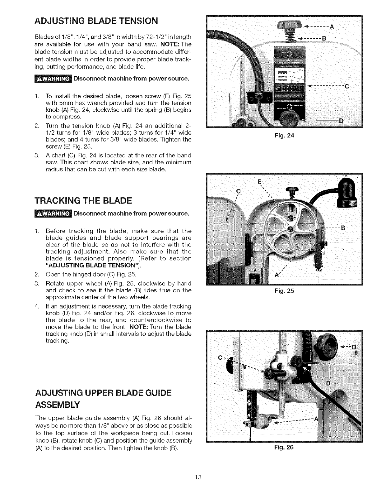
ADJUSTING BLADE TENSION
Blades of 1/8", 1/4", and 3/8" in width by 72-1/2" inlength
are available for use with your band saw. NOTE: The
blade tension must be adjusted to accommodate differ-
ent blade widths in order to provide proper blade track-
ing, cutting performance, and blade life.
Disconnect machine from power source.
1. To install the desired blade, loosen screw (E) Fig. 25
with 5mm hex wrench provided and turn the tension
knob (A) Fig. 24, clockwise until the spring (B) begins
to compress.
2. Turn the tension knob (A)Fig. 24 an additional 2-
1/2 turns for 1/8" wide blades; 3 turns for 1/4" wide
blades; and 4 turns for 3/8" wide blades. Tighten the
screw (E) Fig. 25.
3. A chart (C) Fig. 24 is located at the rear of the band
saw. This chart shows blade size, and the minimum
radius that can be cut with each size blade.
TRACKING THE BLADE
Fig. 24
Disconnect machine from power source.
1. Before tracking the blade, make sure that the
blade guides and blade support bearings are
clear of the blade so as not to interfere with the
tracking adjustment. Also make sure that the
blade is tensioned properly. (Refer to section
"ADJUSTING BLADE TENSION").
2. Open the hinged door (C) Fig. 25.
3. Rotate upper wheel (A) Fig. 25, clockwise by hand
and check to see if the blade (B) rides true on the
approximate center of the two wheels.
4. If an adjustment is necessary, turn the blade tracking
knob (D) Fig. 24 and/or Fig. 26, clockwise to move
the blade to the rear, and counterclockwise to
move the blade to the front. NOTE: Turn the blade
tracking knob (D) insmall intervalsto adjust the blade
tracking.
ADJUSTING UPPER BLADE GUIDE
Fig. 25
ASSEMBLY
The upper blade guide assembly (A) Fig. 26 should al-
ways be no more than 1/8" above or as close as possible
to the top surface of the workpiece being cut. Loosen
knob (B), rotate knob (C) and position the guide assembly
(A)to the desired position. Then tighten the knob (B).
Fig. 26
13
Page 14
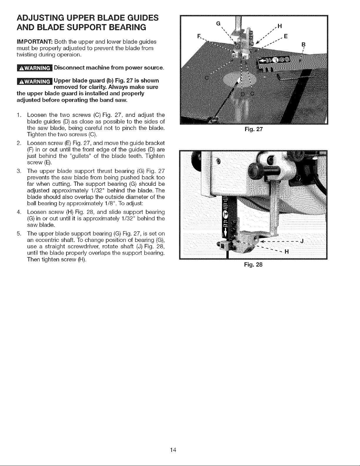
ADJUSTING UPPER BLADE GUIDES
AND BLADE SUPPORT BEARING
IMPORTANT." Both the upper and lower blade guides
must be properly adjusted to prevent the blade from
twisting during operaion.
Disconnect machine from power source.
Upper blade guard (b) Fig. 27 is shown
removed for clarity. Always make sure
the upper blade guard is installed and properly
adjusted before operating the band saw.
1. Loosen the two screws (C) Fig. 27, and adjust the
blade guides (D) as close as possible to the sides of
the saw blade, being careful not to pinch the blade.
Tighten the two screws (C).
2. Loosen screw (E) Fig. 27, and move the guide bracket
(F) in or out until the front edge of the guides (D) are
just behind the "gullets" of the blade teeth. Tighten
screw(E).
3. The upper blade support thrust bearing (G) Fig. 27
prevents the saw blade from being pushed back too
far when cutting. The support bearing (G) should be
adjusted approximately 1/32" behind the blade. The
blade should also overlap the outside diameter of the
ball bearing by approximately 1/8". To adjust:
4. Loosen screw (H) Fig. 28, and slide support bearing
(G) in or out until it is approximately 1/32" behind the
saw blade.
8.
The upper blade support bearing (G) Fig. 27, is set on
an eccentric shaft. To change position of bearing (G),
use a straight screwdriver, rotate shaft (J) Fig. 28,
until the blade properly overlaps the support bearing.
Then tighten screw (H).
Fig. 27
Fig. 28
14
Page 15
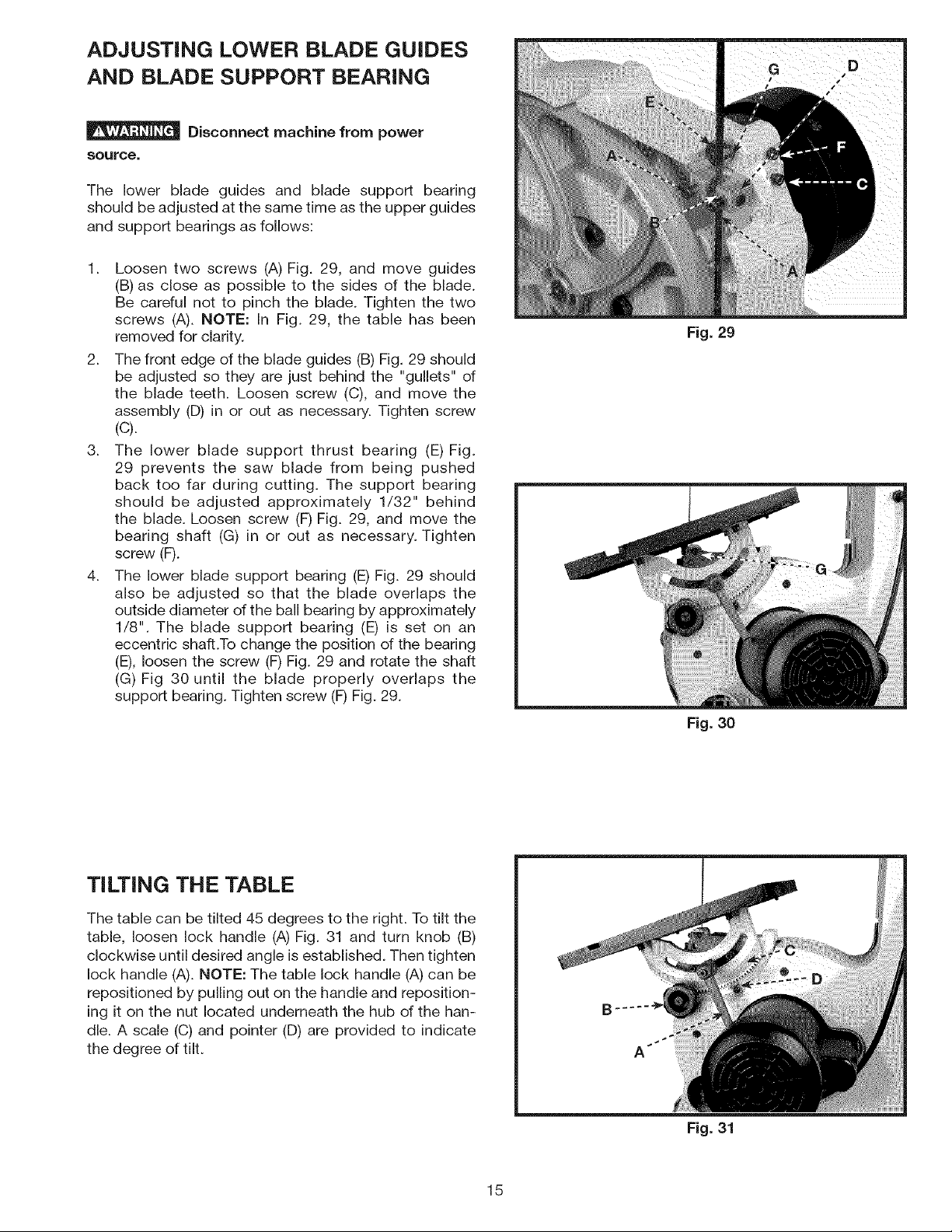
ADJUSTING LOWER BLADE GUIDES
AND BLADE SUPPORT BEARING
Disconnect machine from power
Source.
The lower blade guides and blade support bearing
should be adjusted at the same time as the upper guides
and support bearings as follows:
1. Loosen two screws (A) Fig. 29, and move guides
(B) as close as possible to the sides of the blade.
Be careful not to pinch the blade. Tighten the two
screws (A). NOTE: In Fig. 29, the table has been
removed for clarity.
2. The front edge of the blade guides (B) Fig. 29 should
be adjusted so they are just behind the "gullets" of
the blade teeth. Loosen screw (C), and move the
assembly (D) in or out as necessary. Tighten screw
(C).
3. The lower blade support thrust bearing (E) Fig.
29 prevents the saw blade from being pushed
back too far during cutting. The support bearing
should be adjusted approximately 1/32" behind
the blade. Loosen screw (F) Fig. 29, and move the
bearing shaft (G) in or out as necessary. Tighten
screw (F).
4. The lower blade support bearing (E) Fig. 29 should
also be adjusted so that the blade overlaps the
outside diameter of the ball bearing by approximately
1/8". The blade support bearing (E) is set on an
eccentric shaft.To change the position of the bearing
(E), loosen the screw (F)Fig. 29 and rotate the shaft
(G) Fig 30 until the blade properly overlaps the
support bearing. Tighten screw (F)Fig. 29.
Fig. 29
Fig. 30
TILTING THE TABLE
The table can be tilted 45 degrees to the right. To tilt the
table, loosen lock handle (A) Fig. 31 and turn knob (B)
clockwise until desired angle is established. Then tighten
lock handle (A). NOTE: The table lock handle (A) can be
repositioned by pulling out on the handle and reposition-
ing it on the nut located underneath the hub of the han-
dle. A scale (C) and pointer (D) are provided to indicate
the degree of tilt.
Fig. 31
15
Page 16

ADJUSTING THE TABLE
POSiTiVE STOPS
Positive stops are provided for the table at the 90 and
45 degree angle to the blade. To check and adjust the
positive stops:
Disconnect machine from power
source.
1.
Tilt the table to the 90 degree position as shown in
Fig. 32 and tighten lock handle (A). Place a square
(H) on the table and against the blade and check to
see ifthe blade is 90 degrees to the table surface. If
an adjustment is necessary:
2.
Tilt the table to expose the lock nut (E) Fig. 33.
Loosen lock nut (E) and return table to the 90°
position. With the lock handle (A) Fig. 32 loose, turn
the adjusting screw (F) Fig. 34, using the 3mm hex
wrench provided until the blade is 90 degrees to the
table. Then tighten lock handle (A) and lock nut (E) on
the adjustment screw (F).
Fig. 32
3.
Tilt the table to the 45 degree position as shown
in Fig. 34. Place a square (H) Fig. 34 on the table
and against the blade and check to see if the blade
is 45 degrees to the table surface. If an adjustment
is necessary.
.
Loosen the lock nut (N) Fig. 33 on the adjustment
screw (J) located on the underside of the table. With
the lock handle (A) Fig. 34 loose, turn adjustment
screw (J) using 3mm hex wrench provided until
the blade is 45 degrees to the table. Tighten lock
handle (A) and lock nut (N) on the adjustment screw
(d).
Fig. 33
Fig. 34
16
Page 17
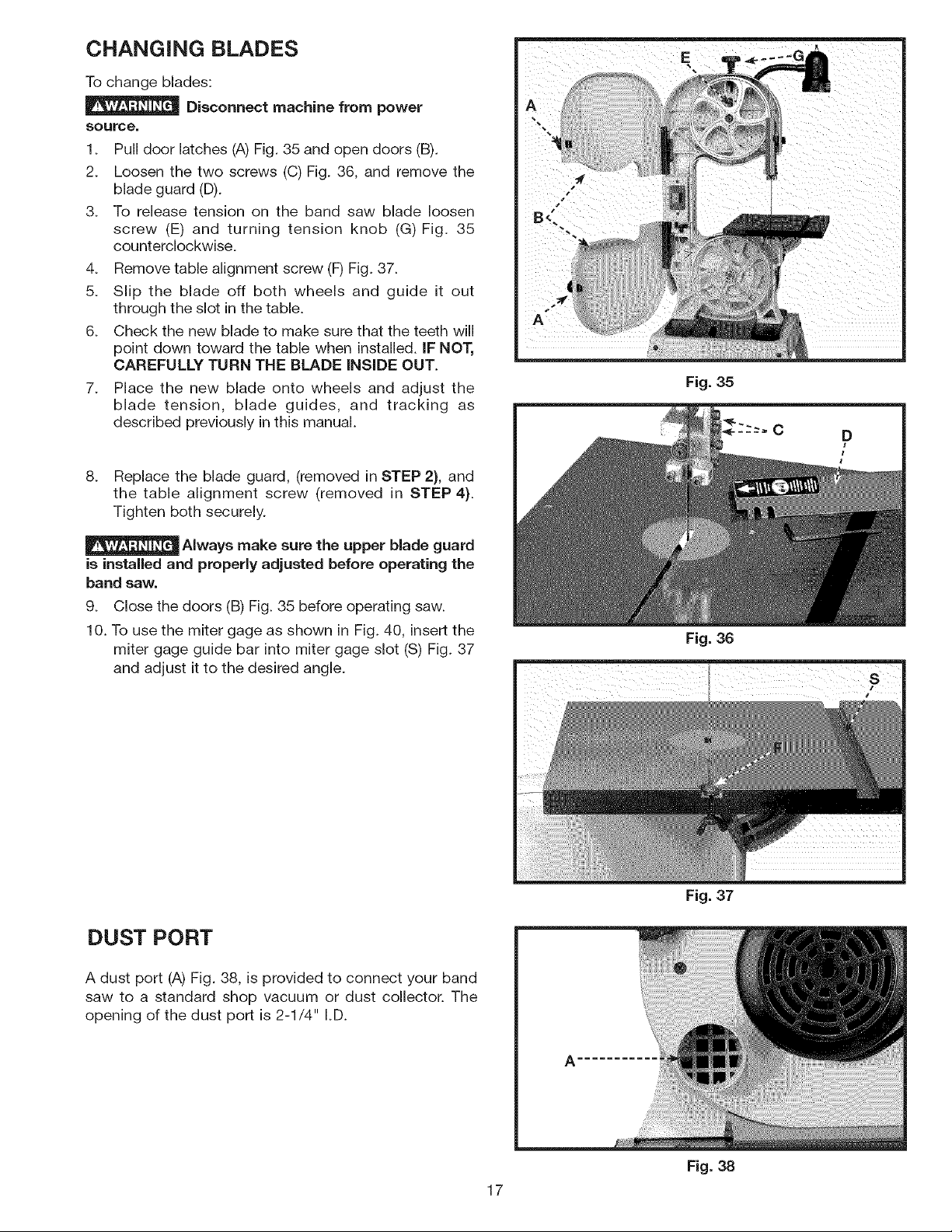
CHANGING BLADES
To change blades:
Disconnect machine from power
source.
1. Pull door latches (A) Fig. 35 and open doors (B).
2. Loosen the two screws (C) Fig. 36, and remove the
blade guard (D).
3. To release tension on the band saw blade loosen
screw (E) and turning tension knob (G)Fig. 35
counterclockwise.
4. Remove table alignment screw (F) Fig. 37.
5. Slip the blade off both wheels and guide it out
through the slot in the table.
6. Check the new blade to make sure that the teeth will
point down toward the table when installed, iF NOT,
CAREFULLY TURN THE BLADE iNSiDE OUT.
7. Place the new blade onto wheels and adjust the
blade tension, blade guides, and tracking as
described previously in this manual.
8. Replace the blade guard, removed in STEP 2), and
the table alignment screw (removed in STEP 4).
Tighten both securely.
Fig. 35
Always make sure the upper blade guard
is installed and properly adjusted before operating the
band saw.
9. Close the doors (B) Fig. 35 before operating saw.
10. To use the miter gage as shown in Fig. 40, insertthe
miter gage guide bar into miter gage slot (S) Fig. 37
and adjust it to the desired angle.
DUST PORT
A dust port (A) Fig. 38, is provided to connect your band
saw to a standard shop vacuum or dust collector. The
opening of the dust port is 2-1/4" I.D.
Fig. 36
Fig. 37
17
Fig. 38
Page 18
Before starting the machine, see that all adjustments are properly made and the guards are in place. Turn the upper
wheel by hand to make sure that everything is correct BEFORE turning on the power.
Keep the top guide within 1/8" of the work piece at all times. Do not force the material against the blade. Light pressure
on the work piece will produce a smoother cut, and prevent excess friction, heating, and hardening of the blade.
KEEP THE SAW BLADE SHARP. Very little forward pressure is required for normal cutting. Keep the workpiece mov-
ing at a slow and consistent rate against the blade to ensure a smooth and accurate cut.
Avoid twisting the blade by trying to turn sharp corners. Remember, you must saw around corners.
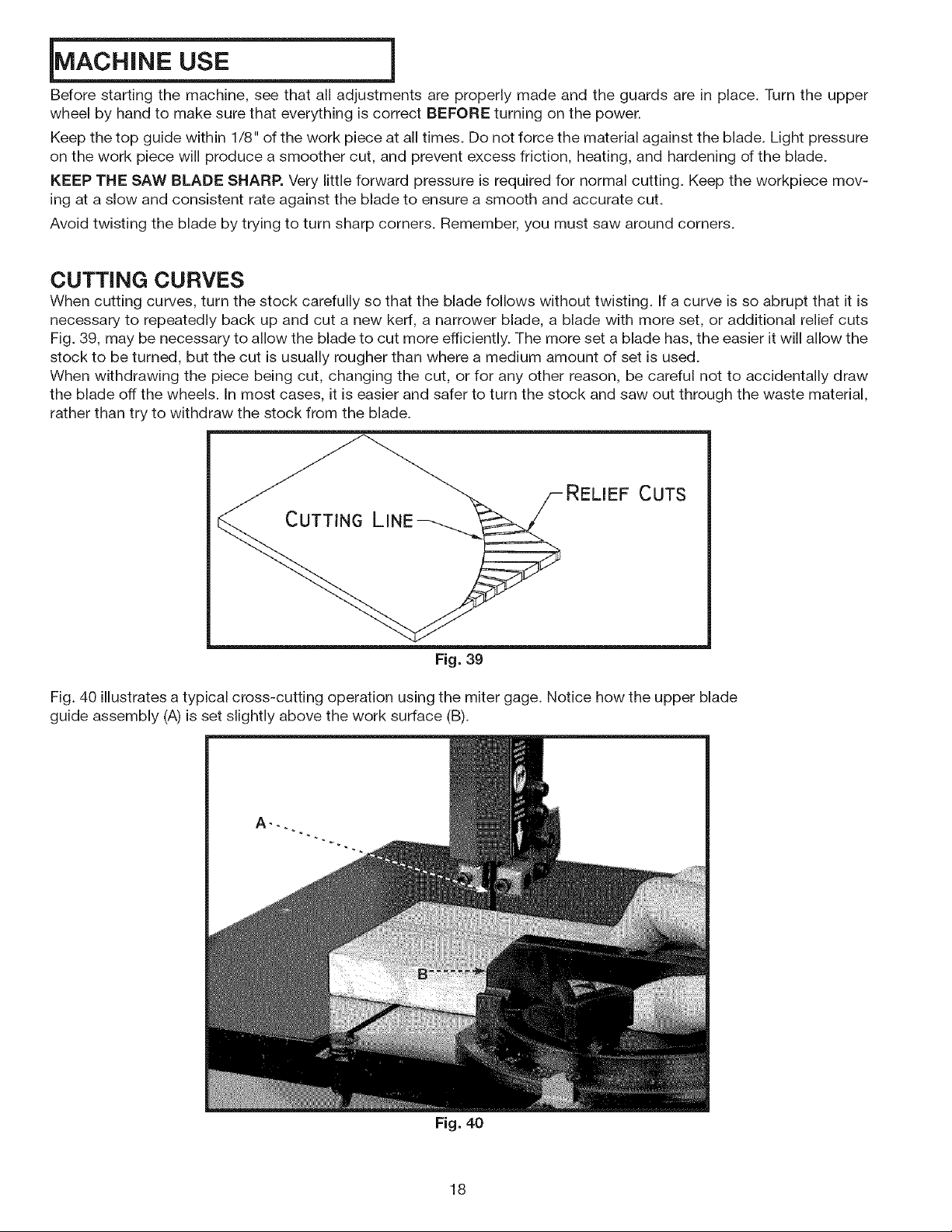
CUTTING CURVES
When cutting curves, turn the stock carefully so that the blade follows without twisting. If a curve is so abrupt that it is
necessary to repeatedly back up and cut a new kerf, a narrower blade, a blade with more set, or additional relief cuts
Fig. 39, may be necessary to allow the blade to cut more efficiently. The more set a blade has, the easier it will allow the
stock to be turned, but the cut is usually rougher than where a medium amount of set is used.
When withdrawing the piece being cut, changing the cut, or for any other reason, be careful not to accidentally draw
the blade off the wheels. In most cases, it is easier and safer to turn the stock and saw out through the waste material,
rather than try to withdraw the stock from the blade.
RELIEF CUTS
CUTTING LINE
Fig. 39
Fig. 40 illustratesa typical cross-cutting operation using the miter gage. Notice how the upper blade
guide assembly (A) is set slightly above the work surface (B).
Fig. 40
18
Page 19
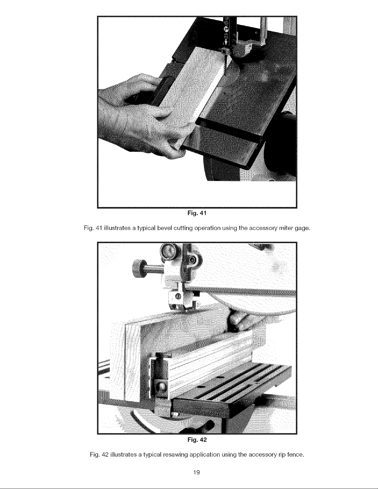
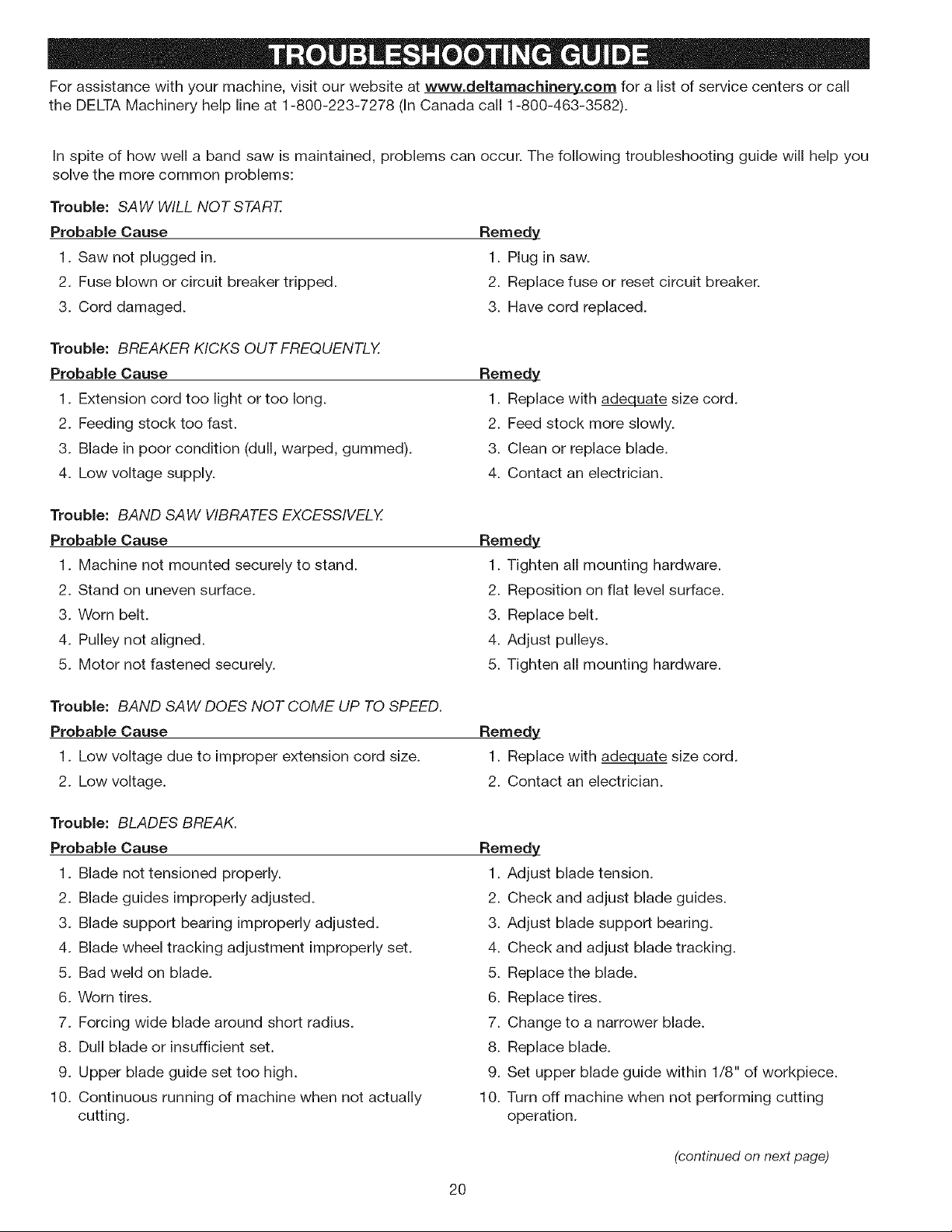
Fig.41
Fig.41illustratesatypicalbevelcuttingoperationusingtheaccessorymitergage.
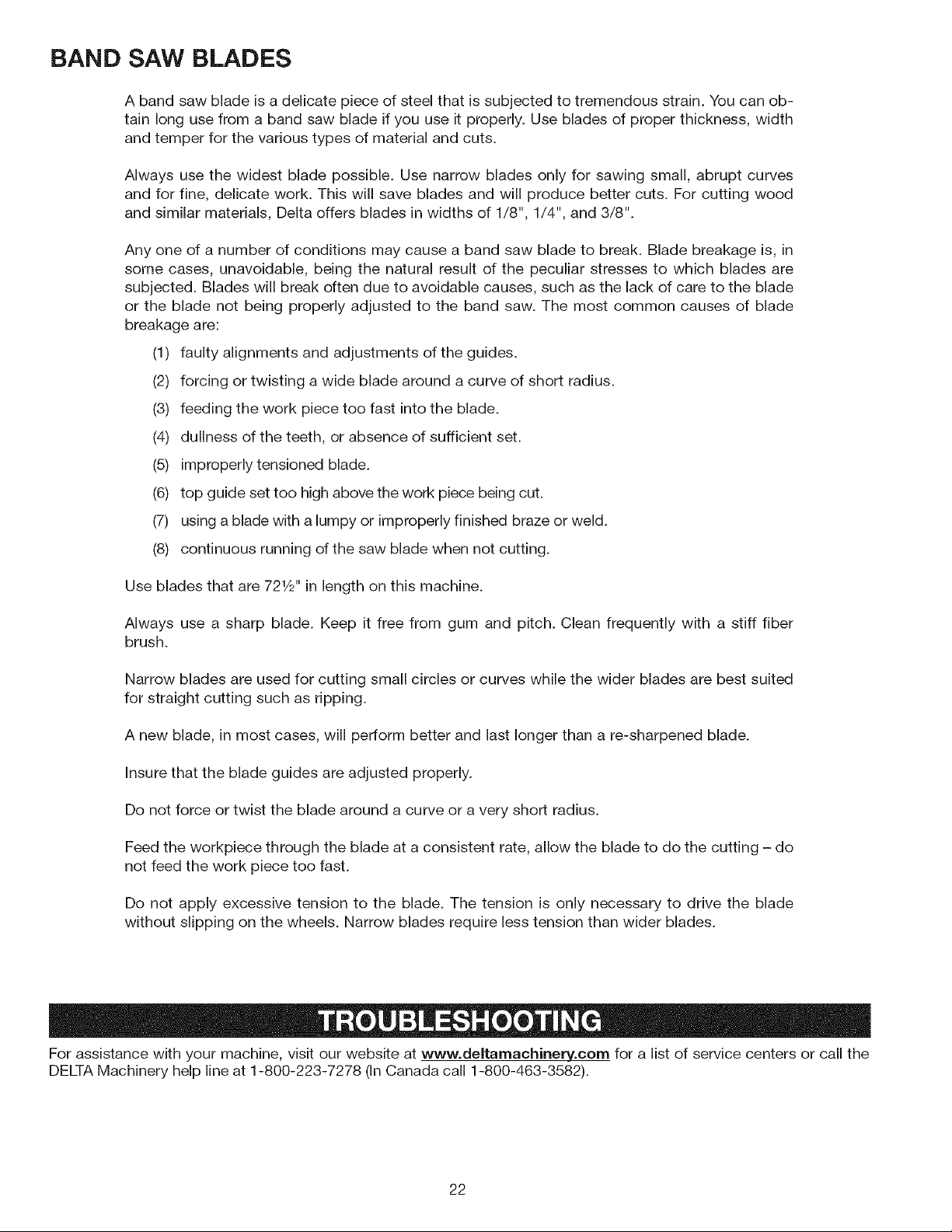
Fig.42
Fig.42illustratesatypicalresawingapplicationusingtheaccessoryripfence.
19
Page 20
Forassistancewithyourmachine,visitourwebsiteatwww.deltamachinery.com for a list of service centers or call
the DELTA Machinery help line at 1-800-223-7278 (In Canada call 1-800-463-3582).
In spite of how well a band saw is maintained, problems can occur. The following troubleshooting guide will help you
solve the more common problems:
Trouble: SAW WILL NOT START.
Probable Cause
1. Saw not plugged in.
2. Fuse blown or circuit breaker tripped.
3. Cord damaged.
Trouble: BREAKER KICKS OUT FREQUENTLY.
Probable Cause
1. Extension cord too light or too long.
2. Feeding stock too fast.
3. Blade in poor condition (dull, warped, gummed).
4. Low voltage supply.
Trouble: BAND SAW VIBRATES EXCESSIVELY.
Probable Cause
1. Machine not mounted securely to stand.
2. Stand on uneven surface.
3. Worn belt.
4. Pulley not aligned.
5. Motor not fastened securely.
Remedy
1. Plug insaw.
2. Replace fuse or reset circuit breaker.
3. Have cord replaced.
Remedy
1. Replace with adequate size cord.
2. Feed stock more slowly.
3. Clean or replace blade.
4. Contact an electrician.
Remedy
1. Tighten all mounting hardware.
2. Reposition on flat level surface.
3. Replace belt.
4. Adjust pulleys.
5. Tighten all mounting hardware.
Trouble: BAND SAW DOES NOT COME UP TO SPEED.
Probable Cause
1. Low voltage due to improper extension cord size.
2. Low voltage.
Trouble: BLADES BREAK.
Probable Cause
1. Blade not tensioned properly.
2. Blade guides improperly adjusted.
3. Blade support bearing improperly adjusted.
4. Blade wheel tracking adjustment improperly set.
5. Bad weld on blade.
6. Worn tires.
7. Forcing wide blade around short radius.
8. Dull blade or insufficient set.
9. Upper blade guide set too high.
10. Continuous running of machine when not actually
cutting.
Remedy
1. Replace with adecjuate size cord.
2. Contact an electrician.
Remedy
1. Adjust blade tension.
2. Check and adjust blade guides.
3. Adjust blade support bearing.
4. Check and adjust blade tracking.
5. Replace the blade.
6. Replace tires.
7. Change to a narrower blade.
8. Replace blade.
9. Set upper blade guide within 1/8" of workpiece.
10. Turn off machine when not performing cutting
operation.
(continued on next page)
2O
Page 21

Trouble:BLADE WILL NOT TRACK.
Probable Cause
1. Blade too loose
2. Upper wheel not properly adjusted.
3. Improperly adjusted blade support bearing.
Trouble: CUT DOES NOT AGREE WITH SETTING ON THE TILT SCALE.
Probable Cause Remedy
1. Pointer out of adjustment 1. Adjust pointer.
Trouble: BLADE WILL NOT STAY ON WHEEL.
Probable Cause
1. Blade not tensioned properly.
2. Blade guides improperly adjusted.
3. Blade support bearing improperly adjusted.
4. Blade wheel not tracking properly.
5. Bad weld on blade.
6. Worn tires.
Remedy
1. Adjust tension
2. Adjust upper wheel.
3. Adjust blade support bearing.
Remedy
1. Adjust blade tension.
2. Check and adjust blade guides.
3. Adjust blade support bearing.
4. Check and adjust blade tracking.
5. Replace the blade.
6. Replace tires.
Trouble: BAND SAW MAKES UNSATISFACTORY CUTS.
Probable Cause
1. Blade not tensioned properly.
2. Blade guides improperly adjusted.
3. Blade support bearing improperly set.
4. Blade wheel not tracking properly.
5. Bad weld on blade.
6. Worn tires.
7. Incorrect blade for work being done.
8. Dull blade or insufficient set.
9. Upper blade guide set too high.
Remedy
1. Adjust blade tension.
2. Check and adjust blade guides.
3. Adjust blade support bearing.
4. Check and adjust blade tracking.
5. Replace the blade.
6. Replace tires.
7. Change the blade.
8. Replace blade.
9. Set upper blade guide within 1/8" of work piece.
21
Page 22
BAND SAW BLADES
A band saw blade is a delicate piece of steel that is subjected to tremendous strain. You can ob-
tain long use from a band saw blade if you use it properly. Use blades of proper thickness, width
and temper for the various types of material and cuts.
Always use the widest blade possible. Use narrow blades only for sawing small, abrupt curves
and for fine, delicate work. This will save blades and will produce better cuts. For cutting wood
and similar materials, Delta offers blades in widths of 1/8", 1/4", and 3/8".
Any one of a number of conditions may cause a band saw blade to break. Blade breakage is, in
some cases, unavoidable, being the natural result of the peculiar stresses to which blades are
subjected. Blades will break often due to avoidable causes, such as the lack of care to the blade
or the blade not being properly adjusted to the band saw. The most common causes of blade
breakage are:
(1) faulty alignments and adjustments of the guides.
(2) forcing or twisting a wide blade around a curve of short radius.
(3) feeding the work piece too fast into the blade.
(4) dullness of the teeth, or absence of sufficient set.
(5) improperly tensioned blade.
(6) top guide set too high above the work piece being cut.
(7) using a blade with a lumpy or improperly finished braze or weld.
(8) continuous running of the saw blade when not cutting.
Use blades that are 721/2'' in length on this machine.
Always use a sharp blade. Keep it free from gum and pitch. Clean frequently with a stiff fiber
brush.
Narrow blades are used for cutting small circles or curves while the wider blades are best suited
for straight cutting such as ripping.
A new blade, in most cases, will perform better and last longer than a re-sharpened blade.
Insure that the blade guides are adjusted properly.
Do not force or twist the blade around a curve or a very short radius.
Feed the workpiece through the blade at a consistent rate, allow the blade to do the cutting - do
not feed the work piece too fast.
Do not apply excessive tension to the blade. The tension is only necessary to drive the blade
without slipping on the wheels. Narrow blades require less tension than wider blades.
For assistance with your machine, visit our website at www.deltamachinerv.com for a list of service centers or call the
DELTA Machinery help line at 1-800-223-7278 (In Canada call 1-800-463-3582).
22
Page 23

KEEP MACHINE CLEAN
Periodically blow out all air passages with dry compressed
air. All plastic parts should be cleaned with a soft damp
cloth. NEVER use solvents to clean plastic parts. They
could possibly dissolve or otherwise damage the material.
Wear certified safety equipment for
eye, hearing and respiratory protection while using
compressed air.
FAILURE TO START
Should your machine fail to start, check to make sure
the prongs on the cord plug are making good contact
in the outlet. Also, check for blown fuses or open circuit
breakers in the line.
LUBRICATION & RUST PROTECTION
Apply household floor paste wax to the machine table,
extension table or other work surface weekly. Or use a
commercially available protective product designed for
this purpose. Follow the manufacturer's instructions for
use and safety.
To clean cast iron tables of rust, you will need the
following materials: a sheet of mediurr_Scotch-Brite TM
Blending Hand Pad, a can of WD-40 and a can of
degreaser. Apply the WD-40 and polish the table surface
with the Scotch-Brite pad. Degrease the table, then apply
the protective product as described above.
REPLACEMENT PARTS
Use only identical replacement parts. For a parts list or to
order parts, visit our website at servicenet.deltamachiner3&,
corn. You can also order parts from your nearest factory-
owned branch, or by calling our Customer Care Center at
1-800-223-7278 to receive personalized support from highly-
trained technicians.
SERVICE AND REPAIRS
All quality tools will eventually require servicing and/or
replacement of parts. For information about Delta Machinery,
its factory-owned branches, or an Authorized Warranty
A complete line of accessories is available from your Delta Supplier, Porter-Cable • Delta Factory Service Centers, and
Delta Authorized Service Stations. Please visit our Web Site www.deltamachinery.com for a catalog or for the name of
your nearest supplier.
Since accessories other than those offered by Delta have not been tested with this product, use
of such accessories could be hazardous. For safest operation, only Delta recommended accessories should be
used with this product.
Service Center, visit our website at www.deltamachinery_,
corn or call our Customer Care Center at 1-800-223-7278.
All repairs made by our service centers are fully guaranteed
against defective material and workmanship. We cannot
guarantee repairs made or attempted by others.
You can also write to us for information at Delta Machinery,
4825 Highway 45 North, Jackson, Tennessee 38305 -
Attention: Product Service. Be sure to include all of the
information shown on the nameplate of your tool (model
number, type, serial number, etc.)
23
Page 24

Toregisteryourtoolforwarrantyservicevisitourwebsiteatwww.deltamachinery.com.
Two Year Limited New Product Warranty
Delta will repair or replace, at its expense and at its option, any new Delta machine, machine part, or machine accessory which in normal
use has proven to be defective in workmanship or material, provided that the customer returns the product prepaid to a Delta factory service
center or authorized service station with proof of purchase of the product within two years and provides Delta with reasonable opportunity
to verify the alleged defect by inspection. For all refurbished Delta product, the warranty period is 180 days. Delta may require that electric
motors be returned prepaid to a motor manufacturer's authorized station for inspection and repair or replacement. Delta will not be responsible
for any asserted defect which has resulted from normal wear, misuse, abuse or repair or alteration made or specifically authorized by anyone
other than an authorized Delta service facility or representative. Under no circumstances will Delta be liable for incidental or consequential
damages resulting from defective products. This warranty isDelta's sole warranty and sets forth the customer's exclusive remedy, with respect
to defective products; all other warranties, express or implied, whether of merchantability, fitness for purpose, or otherwise, are expressly
disclaimed by Delta.
24
Page 25

r w w
FRAN(_AIS
25
Page 26

_: 'vH - ' ' Life et comprendre toutes instructions d'avertissements et operation avant d'utiliser
n'importe queJ outJJ ou n'importe quel _quipement. En utiJisant les outils ou I'_quJpement, les precautions de s_ret_
fondamentales toujours devraient _tre suivies pour r_duire le risque de blessure personnelJe. L'op_ration d_plac_e,
I'entretien ou la modification d'outils ou d'_quipement ont pour r_sultat la blessure s_rieu× et les dommages
de proprietY. IJ y a de certaines appJicatJons pour Jequel outils et I'_quipement sont con_us. La Delta Machinery
recommande avec force que ce produit n'ait pas modifi_ et/ou utJJis_ pour I'application autrement que pour lequel iJ
a _t_ con_u.
Si vous avez n'importe quelles questions relatives & son application n'utilisent pas le produit jusqu'& ce que vous avez ecrit
Delta Machinery et nous vous avons conseille.
La forme en ligne de contact & www.deltamachinery.com
Courrier Postal: Technical Service Manager
Delta Machinery
4825 Highway 45 North
Jackson, TN 38305
Information en ce qui concerne I'op_ration sore et correcte de cet outil est disponible des sources suivantes:
Power Tool Institute
1300 Sumner Avenue, Cleveland, OH 44115-2851
www.powertoolinstJtute.org.
National Safety Council
1121 Spring Lake Drive, Itasca, IL 60143-3201
American National Standards Institute, 25 West 43rd Street, 4 floor, New York, NY 10036 www.ansi.org. ANSI 01.1 Safety
Requirements for Woodworking Machines, and the U.S. Department of Labor regulations www.osha.q_O_
Ce guide contient des renseignements importants gue vous deviez bien saisin Cette information porte sur VOTRE
SECLIRITE et sur LA PREVENTION BE PROBLEMES D'EQUIPEMENT. Afin de vous aider & identifier cette
information, nous avons utilise les symboles ci-dessous. Veuillez life attentivement ce guide en portant une attention
particuli@e a ces sections.
Indique un danger imminent qui, s'iJ n'est pas _vit_, causera de graves blessures ou la mort.
Indique la possibiJit_ d'un danger qui, s'iJ n'est pas _vit_, pourrait causer de graves blessures
ou la mort.
Indique la possibilit_ d'un danger qui, s'iJ n'est pas _vit_, peut causer des dommages a la proprietY.
Sans le symbole d'alerte.lndique la possibiJit_ d'un danger qui, s'il n'est pas _vit_, peut causer des
dommages; mineures ou moyennes.
LA PROPOSiTiON DE CAUFORNIE 65
La poussi_re produite par Je port,age _Jectrique le sciage, le meulage, le pergage et autres
activJt_s de construction peut contenir des produits chimiques qui sont reconnus, par I'_tat de la CaJifomie, de causer
le cancer, les anomalies cong_nitales ou autres mau× de reproduction. Ces produits chJmiques comprennent, entre
autres :
,, le plomb provenant des peintures & base de plomb;
o la silice cristalline provenant de briques, de beton ou d'autres produits de magonnerie
• I'arsenic et le chrome provenant du bois de charpente trait_ chimiquement
Le risque d'exposition & ces produits depend de la fr_quence d'execution de ce genre de travaux. Afin de reduire I'exposition
& ces produits chimiques, travaillez darts un endroit bien a@6 et utilisez de I'equipement de securit_ approuv_, portez toujours
un masque facial ou respirateur homologue MSHA/NIOSH bien ajuste Iorsque vous utilisez de tels outils.
CONSERVEZ CES INSTRUCTIONS!
26
Page 27

L'inobservation de ces r_gles peut conduire b des blessures graves.
1. POUR SA S¢:CURIT_: PERSONNELLE, LIRE LA NOTICE
D'UTILISATION, AVANT DE METTRE LA MACHINE EN
MARCHE, et pour aussi apprendre I'applicationet les limitesde
la machine ainsi que les risques qui lui sont particuliers ainsi, les
possibilit6s d'accident et de blessures seront beaucoup reduites.
2. PORTEZ DES DISPOSITIFS DE PROTECTION DES YEUX
ET DE L'OUi'E. UTILISEZ TOUJOURS DES LUNETTES DE
S#:CURITE. Des lunettes ordinaires ne constituent PAS des
lunettes de securit& UTILISEZ DES }_QUIPEMENTS DE
SURETE HOMOLOGU}_S. Lesdispositifs de protection des yeux
doivent _tre conformes aux normes ANSI Z87.1. Les dispositifs
de protection de I'ouTedoivent _tre conformes aux normes ANSI
$3.19.
3. PORTER UNE TENUE APPROPRIEE. Pas de cravates, de
gants, ni de v_tements amples. Enlever montre, bagues et autres
bijoux. Rouler les manches. Les v_tements ou les bijoux qui
se trouvent pris dans les pieces mobiles peuvent entrainer des
blessures.
4. NE PASUTILISER LA MACHINE DANS UN ENVIRONNEMENT
DANGEREUX. L'utilisation d'outils electriques dans des
endroits humides ou sous la pluie peut entrafner des decharges
electriques ou une electrocution. Garder la zone de travail bien
6clairee pour &viter de tr6bucher ou d'exposer les doigts, les
mains ou les bras & une situation dangereuse.
5. GARDER LES OUTILS ET LES MACHINES EN PARFAIT
_:TAT.Garder les outils aff[_t6set propres afin d'obtenir le meilleur
et le plus sOr rendement. Suivre les instructions pour lubrifier
et changer les accessoires. Les outils et les machines mal
entretenus peuvent se degrader davantage, eVou entrainer des
blessures.
6. INSPECTER LES PI#CES POUR DECELER TOUT DOMMAGE.
Avant d'utiliser la machine, la verifier pour voir s'il n'y a pas de
pi_ces endommagees. Wrifier I'alignement des pieces mobiles
et si ces pieces nese coincent pas, la rupture de pieces, ou toute
autre condition pouvant en affecter le fonctionnement. Toute
piece ou protecteur endommage dolt _tre repar6 ou remplac&
Les pieces endommagees peuvent degrader davantage la
machine et/ou entrafnerdes blessures.
7. GARDER L'AIRE DE TRAVAIL PROPRE. Les zones et etablis
encombres favorisent les accidents.
8. GARDER LES ENFANTS ET LES VlSITEURS A DISTANCE.
L'atelier est un lieu potentiellement dangereux. Les enfants et les
visiteurs peuvent se blesser.
9. _:VITER LE DEMARRAGE ACCIDENTEL. S'assurer que
I'interrupteur est sur <<OFF ,, (ARRCT) avant de brancher le
cordon. En cas de coupure de courant, placer I'interrupteur
& la position <<OFF ,, (ARRE_). Un d6marrage accidentel peut
entrainer des blessures.
10. UTILISER LES DISPOSITIFS PROTECTEURS. Wrifier que tous
les dispositifs protecteurs sont bien en place, bien fixes et en bon
&tat de marche pour eviter les blessures.
11. ENLEVER LES CLES DE REGLAGE ET CELLES DE SERRAGE
AVANT DE METTRE LA MACHINE EN MARCHE. Les outils,
les chutes et les autres debris peuvent _tre projetes violemment
et blesser.
12. UTILISER LA BONNE MACHINE. Ne pas forcer la machine ou
I'accessoire & faire un travail pour lequel il n'a pas et6 con;u.
Des dommages & la machine et/ou des blessures pourraient
s'ensuJvre.
13. UTILISER LES ACCESSOIRES RECOMMAND¢:S. L'utilisation
d'accessoires non recommandes par Delta peut endommager la
machine et blesser I'utilisateur.
14. UTILISER LE CORDON PROLONGATEUR APPROPRIE.
S'assurer que le cordon prolongateur est en bon etat. Lorsqu'un
cordon prolongateur est utilis&, s'assurer que celui-ci est d'un
calibre suffisant pour I'alimentation necessaire & la machine. Un
cordon d'un calibre insuffisant entra_nera une perte de tension
d'o[_ une perte de puissance et surchauffe. Voir le tableau sur
les cordons prolongateurs pour obtenir le calibre approprie selon
la Iongueur du cordon et I'amp&rage de la machine. S'il y a un
doute, utiliser un cordon d'un calibre sup&rieur. Plus le chiffre est
petit, plus lefil est gros.
15. FIXER LA PI#CE. Utilisez les brides ou I'etau quand vous ne
pouvez pas fixer I'objet sur la table et contre la barriere &la main
ou quand votre main sera dangereusement pres de la lame (&
moins de 6").
16. AVANCER LA PI#CE DANS LE SENS CONTRAIRE A LA
ROTATION DE LA LAME, DE LA FRAISE OU DE LA SURFACE
ABRASIVE. L'alimentation dans I'autre sens peut entrainer une
projection violente de lapiece.
17. NE PAS FORCER LA MACHINE EN AVAN(_ANT LA PI#CE
TROP VlTE. Des dommages et/ou des blessures peuvent
s'ensuivre.
18. NE PAS SE PENCHER AU-DESSUS DE LA MACHINE. Une
perte de I'equilibre peut entrafner une chute sur la machine en
marche et causer des blessures.
19. NE JAMAIS MONTER SUR LA MACHINE. On peut se
blesser gravement si la machine bascule ou si I'on touche
accidentellement son outil tranchant.
20. NE JAMAIS LAISSER LA MACHINE EN MARCHE SANS
SURVEILLANCE. COUPER LE COURANT. Ne pas quitter la
machine tant qu'elle n'est pas compl_tement arr_tee. Un enfant
ou un visiteur pourrait se blesseE
21. METTRE LA MACHINE A L'ARR_:T ,, OFF ,, ET LA
Di_BRANCHER avant d'installer ou d'enlever des accessoires,
d'ajuster ou de changer des montages, ou lots des r_parations.
Un demarrage accidentel peut entra_nerdes blessures.
22. METTRE L'ATELIER A L'ABRI DES ENFANTS AU MOYEN
DE CADENAS, D'INTERRUPTEURS PRINClPAUX OU EN
ENLEVANT LES BOUTONS DES DISPOSITIFS DE MISE EN
MARCHE. Le d&marrage accidentel de la machine par un enfant
ou un visiteur peut entrafner des blessures.
23. RESTER ViGiLANT, ATTENTIF, ET FAIRE PREUVE DE BON
SENS. NE PAS UTILISER LA MACHINE LORSQUE L'ON EST
FATIGUe:OU SOUS L'INFLUENCE DE DROGUES, D'ALCOOL
OU DE Mi_DICAMENTS. Un instant d'inattention Iors de
I'utilisation d'outils electriques peut entrainer des blessures
graves.
24. _ L'UTILISATION DE CET OUTIL
PEUT PRODUIRE ET DISPERSER DE LA POUSSI_:RE OU
D'AUTRES PARTICULES EN SUSPENSION DANS L'AIR,
TELLES QUE LA SClURE DE BOIS, LA POUSSI#RE DE
SILIClUM CRISTALLIN ET LA POUSSI#:RE D'AMIANTE.
Dirigez les particules loin du visage et du corps. Faites
toujours fonctionner I'outil dans un espace bien ventile et
prevoyez I'evacuation de la poussiere. Utilisez un systeme
de depoussierage chaque fois que possible. L'exposition
la poussi_re peut causer des problemes de sant_ graves et
permanents, respiratoires ou autres, tels que la silicose (une
maladie pulmonaire grave) et le cancer, et m_me le d_c_s de
la personne affect_e. Evitez de respirer de la poussi_re et de
rester en contact prolonge avec celle-ci. En laissant la poussiere
pen_trer dans vos yeux ou votre bouche, ou en la laissant
reposer sur votre peau, vous risquez de promouvoir I'absorption
de substances toxiques. Portez toujours des dispositifs de
protection respiratoire homologues par NIOSH/OSHA, appropries
&I'exposition & lapoussiere et detaille appropriee, et lavez & I'eau
et au savon les surfaces de votre corps qui ont et_ exposees.
27
Page 28

L'inobservation de ces r_gles peut conduire b des blessures graves.
1. NE PAS FAIRE FONCTIONNER CET APPAREIL
avant qu'il ne soit assembl_ et install_ conform_ment
aux directives.
2. CONSULTER le superviseur, instructeur, ou autre
personne qualifi_e si vous n'_tes pas familiaris6 avec
le fonctionnement de cet outil.
3. SUIVRE TOUSLES CODES DE CABLAGE et les
connexions 61ectriques recommand6es.
4. UTILISER LES DISPOSITIFS DE PROTECTION
CHAQUE FOIS QUE POSSIBLE. V@ifier qu'ils
sont bien en place, correctement r_gl6s, fix6s et
fonctionnent correctement.
5. UTILISER LA BONNE TAILLE DE LAME et le bon
type.
6. AJUSTER LE GUIDE SUPF:RIEUR DE LA LAME
pour qu'il soit environ & 3,2 mm (1/8 po) au-dessus de
la piece.
7. AJUSTER CORRECTEMENT la tension de la lame,
I'alignement, les guides de lame et les roulements
d'appui de la lame.
8. ELOIGNER LES BRAS, MAINS, ET LES DOIGTS de
la lame.
9. EVITER LES OPERATIONS MALADROITES et 6viter
de placer les mains & un endroit ou un glissement
soudain pourrait amener la main sur la lame.
10. NE JAMAIS DF:MARRER L'APPAREIL avant d'avoir
d_barrass6 la table de tousles objets (outils, d6chets
de d_coupe, etc.).
11. NE JAMAIS DI_MARRER UAPPAREIL avec la piece
contre la lame.
12. TENJR FERMEMENT LA PI#CE contre la table. NE
PAS essayer de scier une piece qui ne comporte pas
un c6t_ plat contre la table.
13. TENJR FERMEMENT LA PI#CE et I'acheminer sous
la lame & une vitesse mod@_e.
14. NE JAMAIS SE PENCHER SOUS LA TABLE alors
que I'appareil est en marche.
15. ETEINDRE UAPPAREIL pour reculer Iors d'une coupe
incomplete ou d'une lame coinc_e.
16. FAIRE DES COUPES DE _ REDRESSEMENT ,9avant
de couper de Iongues courbes.
17. F:TEINDRE L'APPAREIL et attendre que la lame
s'immobilise avant de nettoyer la section de la lame,
de retirer les d6bris pros de la lame, de retirer et de
fixer la piece ou de modifier I'angle de la table. Une
lame d_bray6e peut _tre dangereuse.
18. NE JAMAIS EFFECTUER D'OPERATIONS DE
TRA(_AGE, D'ASSEMBLAGE, ou de r6glage sur
la table/l'espace de travail Iorsque I'appareil est en
marche.
19. ETEINDRE UAPPAREIL ET COUPER LE COURANT
avant d'installer ou de retirer des accessoires, avant
tout r_glage ou modifications de ceux-ci ou Iors de
r_parations.
20. F:TEINDRE L'APPAREIL, couper le courant, et
nettoyer la table/l'espace de travail avant de quitter
I'appareil. VERROUILLER L'INTERRUPTEUR EN
POSITION _ D'ARR#T,9 pour 6viter toute utilisation
non autoris6e.
21. DES JNFORMATIONS SUPPLEMENTAIRES (c.-
&-d., une vid6o sur la s_curit_), indiquant comment
utiliser des outils 61ectriques correctement et en toute
s6curit6, sont disponibles aupr_s du Power Tool
Institute, 1300 Sumner Avenue, Cleveland, OH 44115-
2851, Etats-Unis (www.powertoolinstitute.com). Des
renseignements sont _galement disponibles aupr_s
du National Safety Council, 1121 Spring Lake Drive,
Itasca, IL 60143-3201 E.-U. Se reporter & la norme
ANSI 01.1 de I'American National Standards Institute
concernant les machines de travail du bois, ainsi
qu'& la r_glementation OSHA 1910.213. du minist@e
am@icaJn du travail.
CONSERVER CES INSTRUCTIONS.
Consultez les souvent et utilisez les pour enseigner de
nouveaux op rateurs.
RACCORDEMENTS leLECTRIQUES
Un circuit 61ectrique s6par6 dolt _tre utilis6 pour les machines. Les ills de ce circuit doivent _tre au moins de calibre 12.
Ce circuitdoit _tre prot_g_ par un fusible temporis_ de 20 A. Si on utilise un cordon prolongateur, ce cordon dolt _tre
trois ills, avoir unefiche & trois broches et une prise de courant & trois cavit_s, mise & la terre qui correspond & la fiche
de la machine. Avant debrancher la machine, s'assurer que I'interrupteur (les interrupteurs) se trouve(nt) en position
,_OFF >_(ARRIt:T) et que le courant_lectrique pr_sente les m_mes caract@istiques que celles qui sont inscrites sur la
machine. Toutes les connexions _lectriquesdoivent _tablir un bon contact. Le fonctionnement sur une basse tension
endommagera la machine.
Ne pas exposer la machine a la pluie, et ne pas I'utiliser darts des endroits humides.
SPC:CIFICATIONS DU MOTEUR
Cette machine est c&bl_e pour un fonctionnement sur un courant alternatif de 120 volts 60 Hz. Avant de brancher la machine,
s'assurer que I'interrupteur setrouve & la position ,, OFF _(ARRET).
28
Page 29

iNSTRUCTiONS DE MISE A LA TERRE
Cette machine dolt _tre raise a la terre pendant son emploi, afin de prot_gerl'utilisateur des d_charges
_lectriques
1. Toutes les machines avec cordon misa la terre: Dans I'eventualite d'un mauvais fonctionnement ou d'unepanne, la
mise & la terre fournit un trajet de moindre r6sistancepermettant de reduire le risque de decharge _lectrique. Cettemachine
est dot6e d'un cordon electrique poss6dant unconducteur de mise & la terre de I'equipement ainsi que d'unefiche mise
& la terre. La fiche dolt _tre branchee dans une prisede courant correspondante, installee de fagon adequate etmise & la
terre conform_ment &tousles codes et reglementslocaux.
Ne pas modifier la fiche fournie - si elle ne s'adapte pas & laprise de courant, il faut faire installer une prise de
courantconvenable par un electricien competent.
Un mauvais raccordement du conducteur de mise & la terrede I'equipement peut entrafner un risque de
decharge61ectrique. Le conducteur poss6dant un isolant avec surfaceext_rieure de couleur verte, avec ou sans rayures
jaunes, estle conducteur de mise b, la terre de I'equipement. Si unereparation ou un remplacement du cordon _lectrique
s'averen_cessaire, ne pas brancher le conducteur de mise & la terrede I'equipement & une borne sous tension.
Consulter un electricien competent ou le personnel de serviceapres-vente si on ne comprend pas entierement
lesinstructions de mise &la terre, ou si I'on doute que la machinesoit correctement mise & la terre.
Utiliser seulement des cordons prolongateurs & trois ills dot_sd'une fiche mise & la terre, & trois broches, et de prises &
troiscavit_s convenant & la fiche de la machine, comme I'illustre lafigure A.
Reparer ou remplacer sans d_lai tout cordon endommage ouus6.
2. Machines avec cordon misa la terre pr_vues pour uneutilisation sur une alimentation nominale inf_rieure
&150volts :Si cette machine est pr_vue pour _tre utilis6e sur un circuit quicomporte une prise semblable & celle illustree
& la figure A, lamachine devra comporter une fiche raise & la terre semblable& celle illustree & la figureA. Un adaptateur
temporairesemblable & celui illustr6 & la figureB, peut _tre utilise pourraccorder cette fiche & une prise & deux cavit6s
comme celleillustree & la figure B, si une prise correctement miss & la terren'est pas disponible. L'adaptateur temporaire ne
dolt _treutilis6 que jusqu'au moment o0 une prise correctement raise& la terre est install6e par un 61ectricien competent.
L'oreillerigide ou autre dispositif semblable de couleur verte, sur ledessus de I'adaptateur, doit _tre connect_ sur une
raise & laterre permanente comme, par exemple une botte & prisescorrectement raise & la terre. Quand un adaptateur est
utilise,celui-ci dolt 6tre retenu en place par une visen metal.
REMARQUE: Au Canada, le Code canadien de I'_lectricit_ne permet pas I'emploi d'un adaptateur temporaire.
Darts tousles cas, s'assurer quela prise en question est bien raise & la terre. Darts le doute, demander
un p_tentde v_rifier la prise.
Bofte & prises raise a la terre
Broches
Lla broche de__
plus Ionguedes trois
Fig. A
CORDON DE RALLONGE
EmpIoyez les cordes
appropri_es de prolongation, s'assurent votre corde
de prolongation est en bon _tat. en utilisant une corde
de prolongation, soyez s_r d'empIoyer un assez Iourd
pour porter le courant de la machine, une corde trop
petite causera une baisse darts la tension secteur, ayant
pour r_sultat la perte de puissance et de surchauffe, fig.
d-1 or d-2, expositions la mesure correcte & employer
selon la Iongueur de corde, en cas de doute, utilisez
la prochaine mesure plus Iourde. plus le hombre de
mesure est petit, plus la corde est Iourde.
Fig. B
MESUR MiNiMUM DE CORDE D'EXTENSION
TAILLES RECOMMANDEES POUR L'CUSAGE AVEC STATIONNAIRES ELECTRIQUES LES OUTILS
Longueur
Estimation
pere
0-6
0-6
0-6
0-5
6-10
6-10
6-10
6-10
10-12
10-12
10-t2
10-12
12-16
12-t6
12-t6
Volts
120
120
120
120
120
120
120
120
120
120
120
120
120
120
120
Totale De
Corde En Mesure De Corde D'Am
Pieds D'E×tension
up to 25 t8 AWG
25-50 t 6 AWG
50-100 t6 AWG
t00-150 t4 AWG
up to 25 t8 AWG
25-50 t6 AWG
50-t00 t4 AWG
t00-150 t2 AWG
up to 25 t6 AWG
25-50 t 6 AWG
50-100 t 4 AWG
t00-150 t2 AWG
up to 25 t4 AWG
25-50 t2 AWG
50 PI PLUS GRANDS QUE NON RECQMMANDES
Fig. D
29
Page 30

AVANT=PROPOS
La scie &ruban Delta module BS150LS de 254 mm (10 po) est dot_e d'un puissant moteur de 1/2 HP mont_ sur rou-
lement & billes pour une performance 61ev_ et une Iongue dur_e. La profondeur de coupe maximale de la scie est de
17,7 cm (7 po). Le module BS150LS est livr_ avec une table en fonte et un robuste socle en acier qui fournit un appui
solide et une hauteur de travail confortable.
REMARQUE : La photo de la couverture du mode d'emploi illustre le mod&le de production actuel. Les autres illustra-
tions de ce mode d'emploi ne sont pr_sentes qu'& titre indicatif et il est possible que les 6tiquettes et accessoires actuels
different des caract_ristiques r_elles de ce module. Ces illustrations ont uniquement pour but d'illustrer latechnique.
7
I
Fig. 1
Fig. 2
1. Scie& ruban
2. (16) ecrous hexagonaux M8
3. (16) rondelles plates de 9,5 mm (3/8 po)
4. 16) rondelles de blocage M8
5. 16) ecrous hexagonaux M8
6. (2) colliers du cordon d'alimentation de la lampe
7. Cle hexagonale de 5 mm
8. CI_ hexagonale de 4 mm
9. Cl_ hexagonale de 3 mm
10. (4) visa t_te hexagonale M8 x 45 mm)
11. (8) rondelles plates de 9,5 mm (3/8 po)
12. (4) rondelles de blocage M8
13. (4) ecrous hexagonaux M8
14. (4) pattes du socle
15. (2) visa pans creux & filetage autofreinant (Nylock)
M6 x 20 mm pour la lampe
16. (2) rondelles de blocage M6 pour la lampe
3O
Page 31

DI'=SEMBALLAGE ET NETTOYAGE
D6semballer soigneusement la machine et toutes les pi_ces de ou des emballage(s) d'exp6dition. Retirer I'huile anti-
corrosion des surfaces non peintes & I'aide d'un chiffon doux humidifi6 avec de I'alcool, du diluant & peinture ou de
I'alcool d6natur6.
N'utiliser pas de solvants hautement volatils tel I'essence, le naphte, I'ac6tone ou du diluant
a laque pour nettoyer.
Apr_s nettoyage, couvrir les surfaces non peintes d'une cire & parquets d'usage domestique de bonne qualit6.
Pour sa propre s_curit_, ne pas brancher I'appareil a une source d'alimentation jusqu'a ce
qu'il soit enti_rement assembl6, ni avant d'avoir lu et compris I'int_gralit_ de ce mode d'emploi.
OUTILS Ni_CESSAIRES POUR L'ASSEME}LAGE
1. Cle hexagonale de 3 mm - fournie
2. Cle hexagonale de 4 mm - fournie
3. Cle hexagonale de 5 mm - fournie
4. Douille M8 - non fournie
5. Cle M8 - non fournie
DURI_E ESTIMi'=E POUR L'ASSEME}LAGE :
env. 2 & 3 heures.
ASSEMBLAGE DU SOCLE
1. Assembler le socle comme I'illustre la fig. 4, & I'aide
des pi_ces pr6sent6es & la fig. 3. Les traverses et
les pattes sont identifi6es par les m6mes lettres
sur les deux photos. Ins6rer les vis de carrosserie
M8x16 mm dans les pattes et les traverses puis
enfiler les rondelles plates de 9,5 mm (3/8 pc), suivies
des rondelles de blocage M8 et fixer solidement avec
les 6crous hexagonaux M8. Pour le moment, serrer
les 6crous &la main seulement.
REIVIARQUE : positionner les bords sup6rieurs des
traverses sup6rieures (A) par-dessus les traverses avant
et arri@e (B).
2. Ins6rer les quatre pieds de plastique (1) fig. 4, au bas
de chaque patte (L).
Fig. 4
ASSEMBLAGE DE LA SClE/_ RUE}AN AU
SOCLE
1. La fig. 5 illustre les quatre trous d6bouchants (A) qui
fixeront la scie & ruban au socle.
2. Installer la scie & ruban sur le dessus du socle et
aligner les trous (A) fig. 5, avec ceux (D) fig. 6, des
traverses sup6rieures du socle.
Fig. 5
31 Fig. 6
Page 32

3_
Enfiler une rondelle plate de 9,5 mm (3/8 po) (H) fig.
7, sur la vis & t6te hexagonale M8 x 45 mm. Ins@er
la vis dans le trou de la scie & ruban et dans le trou
du socle. R6p6ter I'assemblage pour les trois autres
trous.
4_
Enfiler une rondelle plate de 9,5 mm (3/8 po) sur
la vis (D) fig. 8, suivi d'une rondelle de blocage M8
puis visser un _crou hexagonal et serrer solidement.
R6p6ter I'assemblage pour les trois autres trous.
5_ Pousser sur le dessus de la scie & ruban et s'assurer
que les quatre pattes du socle s'appuient sur la
surface portante. Serrer toute la quincaillerie du
socle.
Fig. 7
ASSEMBLAGE DE LA TABLE SUR
L'APPAREIL
Retirer le levier de verrouillage de la table (A) fig. 1O,
et le bouton d'inclinaison de la table (B). Veuillez
prendre soin de ne pas perdre ces pi_ces. (Ces
composants ont _t6 assembl6s & I'usine & des fins
de transport seulement.)
2_
Retirer la vis d'arr_t, la rondelle et 1'6crou papillon
de la rainure de la table (consulter la fig. 17 pour les
d6tails). Veuillez prendre soin de ne pas perdre ces
pi_ces.
3_
Installer la table (H) fig. 11, sur le b&ti de la scie
ruban de sorte que les vis d'arr_t (K) d6passent par
la rainure du tourillon (L).
Fig. 8
Fig. 10
32
Fig. 11
Page 33

4. Remonterlegoujondu levierdeverrouillage(G)fig.
12,parlarainuredutourillon(L)puisleserreravecla
poign6edulevierdeverrouillage(consulterI'encart).
5. Lafig. 13illustrele levierdeverrouillaged_mont6
(retir6&I' F:TAPE 1). L'article (B) est une rondelle
plate M10, (G) un goujon, (A) un levier de verrouillage,
(E)un ressort, (D)une vis & 6paulement et (C) une cl6
hexagonale de 4 mm.
6. Remonter la vis (D) fig. 13A et la serrer avec la cl_
hexagonale de 4 mm fournie.
Fig. 12
Fig. 13
7_
La fig. 14 illustre le bouton d'inclinaison de la table
(N), le ressort (O) et la vis sp_ciale (P), retires &
I'ETAPE 1.
8_
Remonter le bouton d'inclinaison de la table (N)
fig. 15, au dos de la scie de sorte que les dents du
pignon du bouton (N) s'engagent dans les dents du
tourillon (R). Le fixer & I'aide de la vis sp_ciale (P) et
du ressort avec la cl6 hexagonale de 4 mm fournie.
Fig. 13A
Fig.14
33
Fig.15
Page 34

9. Desserrerlavis(1-)fig.16,etalignerlepointeur(S)
avecle rep@ez@ode 1'6chelledu tourillon(M).
Serrersolidement.
REMARQUE:s'assurerquelatableestperpendicu-
laire&lalameouv@ifierI'alignementdupointeurune
loisquelesbuttesdelatableont6t6r6gl6es(consulter
larubrique<<RI_GLAGE DES BUTI_ES POSiTiVES DE
LA TABLE ,,).
10. Remettre la vis (W) fig. 17, qui a _t_ retiree
I'IeTAPE 2, dans le trou de la table. Enfiler une
rondelle plate M6 (Z) sur la vis M6 x 30 mm puis
visser I'_crou papillon M6 (X) sur la vis (W) et serrer
solidement.
Fig.16
FIXATION DE LA LAMPE SUR L'APPAREIL
1. Fixer le support de la lampe (A) fig. 18, sur le
couvercle sup@ieur de I'appareil & I'aide de deux
vis & pans creux _ filetage autofreinant (Nylock)
M6 x 20 mm (B) et de rondelles de blocage M6.
Serrer solidement avec la cl_ hexagonale de 5 mm
fournie.
2. D_coller I'endos des colliers de la lampe (C) fig.
19, et installer un collier _ chaque endroit illustr_.
S'assurer que le cordon de la lampe soit achemin6
loin de la lame, puis fixer le cordon d'alimentation (D)
aux colliers de cordon (C) fig. 19.
3. La lampe flexible fonctionne ind_pendamment de
la scie & ruban. Pour allumer ou 6teindre la lampe,
tourner I'interrupteur (E)fig. 19.
Fig. 17
Fig. 18
Pour r_duire les risques
d'incendie, utiliser une ampoule de type sur rail
r_flecteur de 40 watts (ou moins} de 120 volts (non
fournie). Ne pas utiliser une ampoule normale do-
mestique. L'ampoule de type sur rail a r_flecteur ne
devrait passe prolonger sous le has de I'abat-jour.
Fig. 19
34
Page 35

COMMANDES ET RI_GLAGES OPERATIONNELS
DI_=MARRAGE ET ARRI__T DE LA SClE
S'assurer que I'interrupteur
se trouve sur la position d'arr_t avant de brancher
le cordon d'alimentation darts la prise. Ne pas
toucher aux lames m_talliques de la fiche Iors du
branchement ou d_branchement du cordon.
L'interrupteur ,,ON/OFF _ (MARCHE/ARRIt:T) est situ6
surle devant de la scie & ruban. Pour mettre la scie EN
MARCHEappuyez sur le bouton (A) fig. 21 & la position
,, ON _(MARCHE). Pour ARRETERla scie, appuyez sur le
bouton(B) fig. 22 & la position ,, OFF _ (ARRET).
VERROUILLER L'INTERRUPTEUR EN
POSITION D'ARRET
IMPORTANT: Lorsque I'outil est inutilis6, I'interrupteur
dolt _tre verrouill_ en position d'arr_t afin d'emp_cher
toute utilisation non autoris_e. Utiliser un cadenas (C)
fig. 31, avec une boucle de 11,11 mm (3/16 po) de di-
ametre.
Fig. 21
En cas de panne d'_lectricit_
(telle un disjoncteur d_sarm_ ou un fusible grill_),
toujours d_placer I'interrupteur en position
d'arr_t jusqu'a ce que I'alimentation soit r_tablie.
Un d_marrage accidentel peut provoquer des
blessures.
OPENING AND CLOSING DOORS
D_brancher I'appareil de la
source d'alimentation.
Lors de r6glages comme un changement ou un aligne-
ment de lame ou un r6glage du guide de lame, etc. les
portes (B) fig. 23, peuvent _tre ouvertes comme suit :
Ne jamais ouvrir la porte Iors-
que I'appareil est en marche.
1. Appuyer sur les deux Ioquets (A) fig. 23, et ouvrir les
porte (B).
2_
La fig. 23A illustre les portes (B) en position ouverte.
3.
Pour fermer et verrouiller les portes (B) fig. 23,
appuyer sur les portes directement au-dessus des
Ioquets (A) jusqu'& ce que les Ioquets s'enclenchent
en position ferm6e.
Fig. 22
Fig. 23
35
Fig. 23A
Page 36

RI_GLAGE DE LA TENSION DE LAME
Des lames de 3,2 mm, 6,4 mm et 9,5 mm (1/8 po, 1/4 po
et 3/8 po) de largeur par 181 cm (72 1/2 po) de Iongueur
sont disponibles pour la scie _ ruban. REMARQUE : la
tension de la lame doit 6tre r6gl6e selon diff6rentes lar-
geurs de lame afin de donner un alignement appropri6
ainsi qu'une performance de coupe et une dur6e de lame
convenables.
D6brancher I'appareil de la
source d'alimentation.
1. Pour installer une lame particuli@e, desserrer la vis
(E) fig. 25, avec la cl6 hexagonale de 5 mm fournie
et tourner le bouton de tension (A) fig. 24, en sens
horaire jusqu'& ce que le ressort (B) commence & se
comprimer.
2. Tourner le bouton de r6glage de la tension (A) fig.
24, 2 tours 1/2 suppl6mentaires pour les lames de
3,2 mm (1/8 po) de largeur, 3tours pour celles de
6,4 mm (1/4 po) et 4 tours pour les lames de 9,5 mm
(3/8 po). Serrer la vis (E)fig. 25.
3. II existe un tableau (C) fig. 24, appos6 & I'arri@e de la
scie & ruban. Ce tableau montre la taille de lame et
le rayon minimum de la courbe qui peut 6tre r6alis6e
avec chaque taille de lame.
Fig. 24
AUGNEMENT DE LA LAME
D_brancher I'appareil de la
source d'alimentation.
Avant d'aligner la lame, s'assurer que les guides de
lame et les roulements d'appui de lame ne touchent pas
la lame.
1. Pour ne pas g6ner le r6glage de I'alignement.
S'assurer 6galement que la tension de la lame est
appropri6e. (Se reporter & la rubrique ,, RF:GLAGE
DE LA TENSION DE LAME ,_).
2. Ouvrir la porte mont6e sur charni@es (C)fig. 25.
3. Tourner & la main la roue sup6rieure (A) fig. 25, en
sens horaire et v6rifier que la lame (B)tourne vraiment
au centre approximatif des deux roues.
4. Si un r6glage s'av@e n6cessaire, tourner le bouton
d'alignement de la lame (D) fig. 24 et/ou fig. 26, en
sens horaire pour d6placer la lame vers I'arri@e et
en sens antihoraire pour la d6placer vers I'avant.
REMARQUE : tourner le bouton d'alignement de la
lame (D)par petits intervalles pour ajuster la lame.
RI_GLAGE DE L'ENSEMBLE DU GUIDE DE
LAME suPf=RIEURE
Fig. 25
L'ensemble du guide de lame sup6rieur (A)fig. 26, dolt
toujours 6tre r6g16& 3,2 mm (1/8 po) maximum au-des-
sus de la surface sup6rieure de la piece & couper ou
aussi pros que possible de cette surface. Desserrer le
bouton (B), tourner le bouton (C) et positionner Fen-
semble du guide (A)& la hauteur voulue. Puis serrer le
bouton (B).
Fig. 26
36
Page 37

REGLAGE DES GUIDES DE LAME
SUPERIEURE ET DU ROULEMENT
D'APPUI DE LAME
IMPORTANT : Les guides de lame sup@ieurs et inf6-
rieurs doivent _tre r_gl_s pour emp_cher la lame de se
tordre en cours de fonctionnement.
D6brancher I'appareil de la
source d'aJimentation.
D_brancher I'appareil de la
source d'alimentation.Upper blade guard (b) Fig. 27
is shown removed for clarity. Always make sure the
upper blade guard is installed and properly adjusted
before operating the band saw.
1. Desserrer les deux vis (C) fig. 27, et r_gler les guides
de lame (D) aussi pros que possible des c6t_s de la
lame de scie en _tant prudent de ne pas pincer la
lame Serrer les deux vis (C).
2. Desserrer la vis (E) fig. 27, et d6placer le support du
guide (F) vers I'int@ieur ou vers I'ext@ieur jusqu'& ce
que le bord avant des guides (D) soient juste derri@e
les ,, gorges >>des dents de lame. Resserrer la vis (E).
3. Le roulement d'appui sup@ieur (G) fig. 27, emp_che
que la lame de scie soit pouss_e trop loin Iors de
la coupe. Le roulement d'appui (G) doit _tre r6g16
environ & 0,8 mm (1/32 po) derri@e la lame. La lame
dewar _galement chevaucher le diametre externe du
roulement d'environ 3,2 mm (1/8 po). Pour effectuer
un r6glage :
4. Desserrer la vis (H) fig. 28, et coulisser le roulement
d'appui (G) vers I'int@ieur ou vers I'ext@ieur jusqu'&
ce qu'il soit & environ 0,8 mm (1/32 po) derri@e la
lame de lascie.
5_
Le roulement d'appui sup@ieur (G) fig. 27, est r6gl_
sur un arbre & excentrique. Pour modifier la position
du roulement (G), utiliser un tournevis droit pour
tourner I'arbre (J) fig. 28, jusqu'& ce que la lame
chevauche correctement le roulement d'appui. Puis
serrer la vis (H).
Fig. 27
Fig. 28
37
Page 38

RI_GLAGE DES GUIDES INFERIEURS DE
LAME ET DU ROULEMENT D'APPUI DE
LAME
Les guides de lame inf@ieureset le roulement d'appui
de la lame doivent 6tre r6gl_s en m_me temps que les
guides sup@ieurs et le roulement d'appui comme suit :
D_brancher I'appareil de la
source d'aJimentation.
1. Desserrer les deux vis (A) fig. 29, et d6placer les
guides (B) aussi pros que possible des c6t_s de
la lame. Prendre soin de ne pas pincer la lame.
Resserrer les deux vis (A). REIVlARQUE : & la fig. 29,
la table a 6t_ retir6e pour plus de clart6.
2. Le bord avant des guides de la lame (B) fig. 29,
devrait _tre r_gl6 de sorte qu'il soit juste derri@e les
,, gorges >>des dents de lame. Desserrer la vis (C) et
d6placer I'ensemble (D) vers I'int@ieur ou I'ext@ieur
au besoin. Resserrer la vis (C).
3. Le roulement d'appui inf@ieur (E) fig. 29, emp_che
que la lame de scie soit pouss6e trop loin Iors de la
coupe. Le roulement d'appui dolt _tre r6gl6 environ
0,8 mm (1/32 po) derri@e la lame. Desserrer la vis
(F) fig. 29, et d_placer I'arbre de roulement (G) vers
I'int@ieur ou I'ext@ieur au besoin. Resserrer la vis
(F).
4. Le roulement d'appui inf@ieur (E) fig. 29, devrait
_galement _tre r6g16de sorte que la lame chevauche
le diam_tre externe du roulement d'environ 3,2 mm
(1/8 po). Le roulement d'appui de la lame (E) est
r6gl6 sur un arbre & excentrique. Pour modifier la
position du roulement (E), desserrer la vis (F) fig.
29, et tourner I'arbre (G) fig. 30, jusqu'& ce que la
lame chevauche correctement le roulement d'appui.
Resserrer la vis (F)fig. 29.
Fig. 29
INAISON DE LA TABLE
La table peut _tre inclin_e de 45 degr_s vers la droite.
Pour incliner latable, desserrer la poign6e de verrouilla-
ge (A) fig. 31, et tourner le bouton (B) en sens horaire
jusqu'& I'angle voulue. Puis serrer la poign6e de ver-
rouillage (A). REMARQUE : la poign_e de verrouillage
de la table (A) se replace en sortant la poign6e et en la
replagant sur 1'6crou qui se trouve sous le moyeu de la
poign6e. Une _chelle (C) et un pointeur (D)sont fournis
pour indiquer I'angle d'inclinaison.
Fig. 30
Fig. 31
38
Page 39

RC:GLAGE DES BUTC:ES POSiTiVES DE LA
TABLE
D_brancher I'appareil de la
source d'alimentation.
Les buttes positives sont fournies pour permettre le
r6glage de la table & 90 et 45 degr6s par rapport & la
lame. Pour v@ifier et r_gler celles-ci, proc_der comme
suit :
Incliner la table & 90 degr_s comme I'illustre la fig.
32 et serrer la poign_e de blocage (A). Placer une
6querre (H) sur la table et contre la lame et v@ifier si
la lame est perpendiculaire & la surface de la table. Si
un r6glage s'av@e n6cessaire :
2_
Incliner la table pour exposer le contre-6crou (E) fig.
33. Le desserrer et remettre la table & 90 degr6s.
La poign_e de blocage (A) fig. 32, 6tant desserr_e,
tourner la vis de r_glage (F) fig. 34, & I'aide de la
cl_ hexagonale de 3 mm fournie jusqu'& ce que la
lame soit perpendiculaire & la table. Puis resserrer la
poign6e de blocage (A) et le contre-6crou (E) sur la
vis de r6glage (F).
Fig. 32
3_
Incliner la table & 45 degr_s comme I'illustre la figure
34. Placer une 6querre (H) fig. 34, sur la table et
contre la lame et v@ifier si la lame est & 45 degr6s
par rapport & la surface de la table. Si un r_glage
s'av@e n_cessaire.
4_
Desserrer le contre-6crou (N) fig. 33, sur la vis de
r_glage (J) se trouvant sous la table. La poign6e de
blocage (A) fig. 34 _tant desserr_e, tourner la vis de
r_glage (J) avec la cl6 hexagonale de 3 mm fournie
jusqu'& ce que la lame soit & 45 degr_s par rapport
la table. Resserrer la poign_e de blocage (A) et le
contre-_crou (N)sur la vis de r_glage (J).
Fig. 33
39
Fig. 34
Page 40

CHANGEMENT DE LAMES
Pour changer les lames :
D_brancher I'appareil de la
source d'alimentation.
1. Appuyer sur les Ioquets (A) fig. 35, ouvrir les portes
(B).
2. Desserrer les deux vis (C) fig. 36, retirer le protege-
lame (D).
3. D6tendre la lame en desserrant la vis (E) et tournant
le bouton de tension (G)fig. 35, en sens antihoraire.
4. Retirer les vis d'alignement de la table (F)fig. 37.
5. Glisser la lame hors des roues et la guider & travers
la rainure dans la table.
6_
V6rifier la nouvelle lame pour s'assurer que les dents
pointeront vers le bas dans la direction de la table
apr_s I'installation. SINON, INVERSER LA LAME
AVEC SOIN.
7. Placer la nouvelle lame sur les roues et r6gler la
tension, les guides de lame et I'alignement selon la
description pr6c_dente dans ce mode d'emploi.
8. Remettre le protege-lame (retir_ & I' ETAPE 2) et
la vis de r_glage de la table (retir6e & I'ETAPE 4).
Resserrer les deux solidement.
Fig. 35
Toujours s'assurer que le pro-
t_ge=lame sup_rieur soit en place et correctement
r_gl_ avant d'utiliser la scie a ruban.
9. Fermer les portes (B)fig. 35, avant d'utiliser la sole.
10. Pour utiliser le guide d'onglet comme I'illustre la fig.
40, ins6rer la barre du guide d'onglet dans la rainure
& cet effet (S) fig. 37, et le r_gler & I'angle voulu.
GOULOTTE POUSSIERE
Fig. 36
Fig. 37
Une goulotte & poussi_re (A)fig. 38, est prevue pour
permettre le raccordement de la scie & ruban & un as-
pirateur d'atelier ou un syst_me de captation de pous-
si_re. L'ouverture de la goulotte comporte un diametre
interne de 57,1 mm (2 1/4 po)
Fig. 38
4O
Page 41

UTILISATION DE L'APPAREIL
Avant de d6marrer I'appareil, v@ifier si tousles r_glages sont bien _tablis et si les dispositifs de protection sont en
place. Tourner la roue sup@ieure & la main pour s'assurer que tout soit bien AVANT de mettre la scie en marche.
Garder le guide sup@ieur & environ 3,2 mm (1/8 po) de la piece en tout temps. Ne pas forcer le mat@iau contre la
lame. Une 16g@epression sur la piece produira une coupe plus nette et pr6viendra la friction excessive, la surchauffe
et le durcissement de la lame.
TENIR LA LAME BIEN AFFOTEE. II faut tr_s peu de pression pour une coupe normale. D_placer la piece lentement
vitesse r_guli@e contre la lame pour assurer une coupe precise et lisse. Eviter de tordre la lame en essayant d'ex_-
cuter des courbes trop prononc6es. Se rappeler que vous devez scier autour des coins.
COUPE DE COURBES
Lors de la coupe de courbes, tourner la piece avec soin pour que la lame suive la ligne de coupe sans se tordre. Si
une courbe est si prononc6e qu'il faut continuellement reculer et couper un nouveau trait, il faudra peut-_tre une lame
plus _troite, avec plus de vole ou ex_cuter des coupes suppl_mentaires de redressement fig. 39, pour permettre & la
lame de couper de mani@e plus efficace. Plus la lame a de vole, plus facile ce sera de tourner la piece, mais la coupe
est normalement plus grossi@e qu'avec une lame & vole moyenne. En retirant la piece coup6e, en changeant la
coupe ou pour toute autre raison, attention de ne pas retirer accidentellement la lame des roues. Dans la plupart des
cas, il est plus facile et moins dangereux de tourner la piece et de scier le mat@iau de rebut plut6t que d'essayer de
retirer la piece de la lame.
F CUTS
CUTTING
Fig. 39
La fig. 40 illustre une op@ation de tron(2onnage type & I'aide du guide d'onglet. Remarquer comment I'ensemble du
guide de lame sup@ieure (A) est r6g16 un peu au-dessus de la surface de travail (B).
Fig. 40
41
Page 42

Fig.41
Lafig.41illustreunfonctionnementtypedecoupeenbiseau&I'aided'unguided'ongletsenaccessoire.
Fig.42
Lafig.42montreuneapplicationtypederecoupeenutilisantunguidelongitudinalenaccessoire.
42
Page 43

PourobtenirdeI'aideausujetdeI'outil,consulternotresiteWebwww.deltamachinery.compourobteniruneliste
descentresder_parationoucomposerle1-800-223-7278duCentreded6pannageDELTAMachinery(auCanada,
composerle1-800-463-3582).
Malgr6unbonentretiendelascie&ruban,desproblemespeuventsurgir.Leguideded6pannagesuivantvousaidera
r_soudrelesprobl_meslespluscourants.
Probl_me : LA SCIE NE DE-MARRE PAS.
Cause probable
1. Scie non branch_e
2. Fusible grill_ ou disjoncteur d6clench_
3. Cordon endommag&
Probl_me : LE DISJONCTEUR SE DE-CLENCHE FRE-QUEMMENT.
Cause probable
1. La rallonge est trop I_g@e ou trop Iongue.
2. Acheminement de la piece trop rapide.
3. La lame est en mauvais 6tat (6mouss6e, voil_e,
encoll_e).
4. Basse tension fournie.
Probl_me : LA SCIE A RUBAN VIBRE BEAUCOUR
Cause probable
1. Uappareil n'est pas bien fix6 au socle.
2. Socle plac_ sur un sol in,gal.
3. Courroie us6e.
4. Poulie non align6e.
5. Le moteur n'est pas bien fix&
Solution
1. Brancher la scie.
2. Remplacer le fusible ou r_initialiser le disjoncteur
3. Remplacer le cordon.
Solution
1. La remplacer par une rallonge de
taille adequate.
2. Acheminer la piece plus lentement.
3. Nettoyer ou remplacer la lame.
4. Communiquer avec un 61ectricien.
Solution
1. Visser bien toute la quincaillerie de fixation.
2. Le replacer sur un sol plan.
3. Remplacer la courroie.
4. R6gler les poulies.
5. Visser bien toute la quincaillerie de fixation.
Probl_me : LA SCIE A RUBAN N'ATTEINT PAS SON REGIME.
Cause probable
1. Basse tension & cause d'une rallonge mal
dimensionn6e.
2. Basse tension.
Probl_me : LES LAMES CASSENT.
Cause probable
1. La tension de la lame n'est pas appropri_e.
2. Les guides de lame sont mal r6gl_s.
3. Le roulement d'appui de lame est mal r6gl&
4. Le r6glage de I'alignement de roue de lame
est incorrect.
5. Mauvaise soudure de lame.
6. Pneus uses.
7. Forcer une lame large & couper avec un court rayon.
8. Lame _mouss6e ou voie insuffisante.
9. Le guide pour lame sup@ieure est r6g16trop haut.
10. Fonctionnement de I'appareil Iorsqu'il ne coupe
Solution
1. La remplacer par une rallonge de taille ad6quate.
2. Communiquer avec un 61ectricien.
Solution
1. R6gler la tension de la lame.
2. V@ifier et r6gler les guides de lame.
3. R_gler le roulement d'appui de lame.
4. V@ifier et r6gler I'alignement de la lame.
5. Remplacer la lame.
6. Remplacer les pneus.
7. Changer pour une lame plus _troite.
8. Remplacer la lame.
9. R6gler le guide de lame sup@ieure & 32 mm (1/8 pc) de la
piece.
10.€:teindre I'appareil Iorsque vous ne coupez pas
43
(suite...)
Page 44

Probl_me : LA LAME NE S'ALIGNE PAS
Cause probable
1. Lame trop d6tendue
2. La roue sup@ieure est mal r6gl6e.
3. Roulement d'appui de la lame mal r_gl&
Probl_me : LA COUPE NE CORRESPOND PAS AU REGLAGE SUR L'_-CHELLE D'INCLINAISON.
Cause probable Solution
1. Pointeur d@6g16 1. R6gler le pointeur
Probl_me : LA LAME NE RESTE PAS SUR LA ROUE.
Cause probable
1. La tension de la lame n'est pas appropri_e.
2. Les guides de lame sont mal r6gl_s.
3. Le roulement d'appui de lame est mal r_gl&
4. La roue de la lame est mal align6e.
5. Mauvaise soudure de lame.
6. Pneus uses.
Probl_me : LA SCIE A RUBAN COUPE DE MANIERE INSATISFAISANTE.
Cause probable
1. La tension de la lame n'est pas appropri6e.
2. Les guides de lame sont mal r6gl_s.
3. Le roulement d'appui de la lame est mal r6gl&
4. La roue de la lame est mal align6e.
5. Mauvaise soudure de lame.
6. Pneus uses.
7. Lame inadequate pour letravail effectu&
8. Lame _mouss_e ou voie insuffisante.
9. Le guide pour lame sup@ieure est r_gl_ trop haut.
Solution
1. R6gler la tension
2. R6gler la roue sup@ieure.
3. R_gler le roulement d'appui de lame.
Solution
1. R6gler la tension de la lame.
2. V@ifier et r6gler les guides de lame.
3. R_gler le roulement d'appui de lame.
4. V@ifier et r_gler I'alignement de la
lame.
5. Remplacer la lame.
6. Remplacer les pneus.
Solution
1. R6gler la tension de la lame.
2. V@ifier et r_gler les guides de lame.
3. R6gler le roulement d'appui de la
lame.
4. V@ifier et r_gler I'alignement de la
lame.
5. Remplacer la lame.
6. Remplacer les pneus.
7. Changer la lame.
8. Remplacer la lame.
9. R6gler le guide de lame sup@ieure
32 mm (1/8 pc) de la piece.
44
Page 45

LAMES DE SCIE .ALAME RUBAN
Une lame de scie &ruban est une pi&ce d'acier d_licate qui dolt supporter beaucoup d'effort. Une utilisation correcte
de la scie &ruban vous offrira un rendement prolong6. Utiliser des lames d'une _paisseur, largeur et trempe ad_qua-
tes pour les divers types de mat6riaux et coupes.
Toujours utiliser la lame la plus large possible. Utiliser des lames 6troites seulement pour la coupe de courbes pro-
nonc6es et le travail fin et d_licat. Ceci prot6gera les lames et produira de meilleures coupes. Pour couper le bois et
autres mat_riaux semblables, Delta offre des lames dans les largeurs suivantes : 3,2 mm, 6,4 mm et 9,5 mm (1/8 po,
1/4 po et 3/8 po).
II existe un certain nombre de conditions sous lesquelles une lame de scie & ruban se casse. Dans certains cas, il est
inevitable que la lame se casse & la suite de contraintes particuli_res dont fait I'objet ce type de lame. Pourtant, sou-
vent la rupture peut _tre 6vit6e avec un bon entretien ou r_glage de la lame. Les causes les plus courantes de rupture
de lame sont :
(1) les mauvais alignements et r6glages des guides.
(2) forcer ou tordre une lame large autour d'une courbe de court rayon.
(3) acheminer la piece trop rapidement sur la lame.
(4) dents _mouss6es ou voie insuffisante.
(5) lame mal tendue.
(6) guide sup_rieur r6g16 trop haut au-dessus de la piece & couper.
(7) utilisation d'une lame avec une soudure ou un brasage de finition irr6gulier ou incorrect.
(8) fonctionnement continu de I'appareil Iorsqu'il n'est pas utilis_.
Utiliser des lames de 184,1 cm (72 1/2po) de Iongueur sur cet appareil. Utiliser toujours une lame tranchante. La gar-
der libre de gomme et de goudron. La nettoyer fr6quemment avec une brosse &soies dures. Les lames _troites sont
utilis6es pour couper de petits cercles ou courbes tandis que les lames larges conviennent mieux pour les coupes
rectilignes comme le sciage en long.
Une nouvelle lame fonctionnera mieux dans la plupart des cas et durera plus Iongtemps qu'une lame r6affQt6e. S'as-
surer que les guides de lame sont r6gl6s correctement. Ne pas forcer ou tordre la lame autour d'une courbe ou d'un
rayon tr_s court. Acheminer la piece dans la lame & un rythme constant et laisser la lame couper - ne pas acheminer
pas la piece trop rapidement.
Ne pas appliquer de pression excessive sur la lame. La tension n'est n6cessaire que pour entrafner la lame sans pati-
ner sur les roues. Les lames @troites exigent moins de tension que les lames plus larges.
Pour I'assistance avec votre outil, visiter notre site web & www.deltamachinery.com pour une liste de centres de maintenance
ou appeler la ligne d'aide de Delta Machinery & 1-800-223-7278. (Canada: 1-800-463-3582).
45
Page 46

PIECES DE RECHANGE
Utiliser seulement des pieces de rechange identiques.
Pour obtenir une liste des pieces de rechange ou pour
en commander, consulter notre site Web au eervieenet.
deltamachinery.com. Commander aussi des pieces aupres
d'une succursale d'usine ou composer le 1-800-223-7278
pour le service & la clientele et recevoir ainsi une assistance
personnalis_e de techniciens bien formes.
ENTRETIEN ET R¢:PARATION
Tousles outils de qualit6 finissent par demander un
entretien ou un changement de piece. Pour de plus
amples renseignements & propos de Delta Machinery,
ses succursales d'usine ou un centre de r6paration sous
garantie autorise, consulter notre site Web au www.
Une ligne complete des accessoires est fournie des centres commerciaux d'usine de par votre de Porter-CableoDelta
fournisseur, de Porter-CableoDelta, et des stations service autoris6es par Porter-Cable. Veuillez visiter notre site Web
www.deltamachinery.com pour un catalogue ou pour le nom de votre fournisseur plus proche.
Depuis des acceesoires autre que ceux offertspar Porter-CableoDelta n'ont pas _t_ test_e
avec ce produit, utilisation de tels accessoires a pu _tre dangereux. Pour I'exploitation eQre, eeulement Porter-
CableoDelta a recommand_ des accessoires devrait 6tre utilie_ avec ce produit.
deltamachinery.com ou composer le 1-800-223-7278 pour
le service & la clientele. routes les r_parations effectu_es
dans nos centres de reparation sont entierement garanties
contre les defauts de mat6riaux et de main-d'oeuvre. Nous
ne pouvons garantir les reparations effectu_es en partie ou
totalement par d'autres.
Pour de plus amples renseignements par courrier, ecrire
& Delta Machinery, 4825 Highway 45 North, Jackson,
Tennessee 38305, E.-U. - & I'attention de : Product Service.
S'assurer d'indiquer toutes les informations figurant sur
la plaque signaletique de I'outil (numero du modele, type,
numero de s_rie, etc.).
GARDER LA MACHINE PROPRE
D6gager r6guli_rement toutes les conduites d'air avec de Fair comprim6 sec. Toutes les pi_ces en plastique doivent 6tre net-
toy6es a I'aide d'un chiffon doux humide. NE JAMAIS utiliser de solvants pour nettoyer les pi_ces en plastique. Les solvants
peuvent dissoudre ou endommager le mat6riel.
Porter des protections oculaire et auditive homologu_es et utiliser un appareil respiratoire lots de I'utilisation d'air
comprim&
D#:MARRAGE IMPOSSIBLE
Si la machine ne d6marre pas, s'assurer que les lames de la fiche du cordon d'alimentation sont bien enfonc6es dans la prise
de courant. V6rifier 6galement que les fusibles ne sont pas grill6s ou que le disjoncteur ne s'est pas d6clench6.
LUBRIFICATION ET PROTECTION CONTRE LA ROUILLE
Appliquer chaque semaine une cire & parquets d'usage domestique sur la table de la machine, sur la raflonge de table ou
toute autre surface de travail. Ou utiliser un produit protecteur commercial con(2u & cet effet. Suivre les directives du fabricant
pour I'utilisation et la s6curit6.
Pour nettoyer les tables en fonte contre la rouifle, utiliser le mat6riel suivant : une feuifle de papier & poncer Scotch-Brite TM
medium, une bofte de WD-40® et une bofte de d6graissant. Appliquer le WD-40 et polir la surface de la table avec le papier
& poncer Scotch-Brite. D6graisser la table puis appliquer le produit protecteur comme d6crit ci-dessus.
Pour enregistrer votre outil pour la garantie service la visite notre site Web &www.deltamachinery.com.
Garantie limit6e de deux ans
Delta reparera ou remplacera, & ses frais et A sa discr6tion, route nouvelle machine Delta, piece de rechange ou tout accessoire qui,
dans des circonstances d'utilisation normale, s'est av6r6 d6fectueux en raison de d6fauts de materiau ou de fabrication, A condition
que le client retourne le produit (transport pay6 d'avance) au centre de r6paration de I'usine Delta ou & un centre de r6paration autoris6
accompagn6 d'une preuve d'achat et dans les deux ans de la date d'achat du produit, et fournisse a Delta une opportunit6 raisonnable de
v6rifier le d6faut pr6sume par une inspection. La p6riode de garantie des produits Delta r6usin6s est de 180 jours. Delta peut demander
que les moteurs 61ectriques soient retoumes (transport pay6 d'avance) & un centre de reparation autoris6 du fabricant du moteur en vue
d'une inspection, d'une r6paration ou d'un remplacement. Delta ne peut 6tre tenu pour responsable des d6fauts r6sultants de I'usure
normale, de la mauvaise utilisation, de I'abus, de la r6paration ou de la modification du produit, saul en cas d'autorisation sp6cifique
d'un centre de r6paration ou d'un repr6sentant Delta autoris6. En aucune circonstance Delta ne peut _tre tenu pour responsable des
dommages accidentels ou indirects r6sultant d'un produit d6fectueux. Cette garantie constitue la seule garantie de Delta et le recours
exclusif des clients en ce qui concerne les produits defectueux ; toutes les autres garanties, expresses ou implicites, de qualit6
marchande, d'adequation & un usage particulier, ou autre, sent expressement d6clinees par Delta.
46
Page 47

ESPANOL
47
Page 48

Lea y entienda todas advertencias y las instrucciones operadoras antes de utilizar cualquier
instrumento o el equipo. Cuando se usa instrumentos o equipo, las precauciones b&sicas de la seguridad
siempre se deben seguir para reducir el riesgo de la herida personal. La operaci6n impropia, la conservaci6n o la
modificaci6n de instrumentos o equipo podrian tenet como resultado el daSo grave de la herida y la propiedad.
Hay ciertas aplicaciones para que equipaas con herramienta y el equipo se diseSa. La Delta Machinery
recomienda totalmente que este producto no sea modificado y/o utilizado para ninguna aplicaci6n de otra
manera que para que se dise56.
Si usted tiene cualquiera pregunta el pariente a su aplicaci6n no utiliza el producto hasta que usted haya escrito Delta
Machinery y nosotros Io hemos aconsejado.
Laforma en linea del contacto en www. deltamachinery, corn
ElCorreo Postal: Technical Service Manager
Delta Machinery
4825 Highway 45 North
Jackson, TN 38305
(iN CANADA: 125 Mural St. Suite 300, Richmond Hill,ON, L4B 1M4}
Informaci6n con respecto a laoperaci6n segura y apropiada de este instrumentoest_ disponible de lasfuentes siguientes:
Power Tool Institute
1300 Sumner Avenue, Cleveland, OH 44115-2851
ww.powertoolinstitute.org
National Safety Council
1121 Spring Lake Drive, Itasca, IL 60143-3201
American National Standards Institute, 25 West 43rd Street, 4 floor, New York, NY 10036 www.ansi.orq
ANSI 01.1Safety Requirements for Woodworking Machines, and the U.S. Department of Labor regulations www.osha.qov
GUARDE ESTAS INSTRUCCIONES!
Es importante para usted leer y entender este manual. La informaci6n que Io contiene relaciona a proteger SU
SEGURIDAD y PREVENIR los PROBLEMAS. Los simbolos debajo de son utilizados para ayudarlo a reconocer
esta informaci6n.
indica una situaci6n de inminente riesgo, la cual, si no es evitada, causar& la muerte o lesiones serias.
Indica una situaci6n potencialmente riesgosa, que si no es evitada, podria resultar en la muerte o
lesiones serias.
Indica una situaci6n potencialmente peligrosa, la cual, si no es evitada, podria resultar en lesiones
menores o mode=radas.
Usado sin el simbolo de seguridad de alerta indica una situa=ci6n potencialmente riesgosa la que,
si no es evitada, podria causar danos en la propiedad.
PROPOSICION DE CALIFORNIA 65
Algunos tipos de aserrin creados pot m_quinas el_ctricas de lijado, aserrado, amolado,
perforado u otras actividades de la construcci6n, contienen materiales quimicos conocidos (en el Estado de
California) como causantes de c_ncer, defectos de nacimiento u otros da_os del aparato reproductivo. Algunos
ejemplos de dichos productos quimicos son:
= Elplomo contenido en algunas pinturas con base de plomo
• Silice cristalizado proveniente de los ladrillos, el cemento y otros productos de alba_ileria
Ars6nico y cromo de madera tratada quimicamente
Su riesgo por causa de estas exposiciones varia, dependiendo de con cuAnta frecuencia realice este tipo de trabajo. Para
reducir su exposici6n a estos agentes quimicos: trabaje en un Area bienventilada y trabaje con equipo de seguridad aprobado,
use siempre protecci6n facial o respirador NIOSH/OSHA aprobados cuando deba utilizar dichas herramientas.
48
Page 49

Si no se siguen estas normas, el resultado podria set lesiones graves.
1. PARA SU PROPIA SEGURIDAD, LEA EL MANUAL DE
INSTRUCCIONES ANTES DE UTILIZAR LA Mh.QUINA.
AI aprender la aplicaci6n, las limitaciones y los peligros
especfficos de la maquina, se minimizara enormemente la
posibilidad de accidentes y lesiones.
2. USE PROTECCI(DN DE LOS OJOS Y DE LA AUDICION.
USE SIEMPRE ANTEOJOS DE SEGURIDAD. Los lentesde
uso diario NO son anteojos de seguridad. USE EQUIPO DE
SEGURIDAD CERTIFICADO. El equipo de protecci6n de los
ojos debe cumplir con las normas ANSI Z87.1. El equipo de
protecci6n de la audici6n debe cumplir con las normas ANSI
$3.19.
3. USE INDUMENTARIA ADECUADA. No use ropa holgada,
guantes, corbatas, anillos, pulseras u otras joyas que podHan
engancharse en las piezas m6viles. Se recomienda usar
calzado antideslizante. Use una cubierta protectora del pelo
para sujetar el pelo largo.
4. NO UTILIOE LA MAQUINA EN UN ENTORNO PELIGROSO.
La utilizaci6n de herramientas mecanicas en lugares h_medos
o mojados, o en la Iluvia, puede causar descargas electricas
o electrocuci6n. Mantenga bien iluminada el Area de trabajo
para evitar tropezar o poner en peligro los brazos, las manos y
los dedos.
5. MANTENGA TODAS LAS HERRAMIENTAS Y M,_QUINAS
EN CONDICIONES OPTIMAS. Mantenga las herramientas
afiladas y limpias para Iograr el mejor y mas seguro
rendimiento. Siga las instrucciones de lubricaci6n ycambio de
accesorios. Las herramientas y las maquinas mal mantenidas
pueden dafiar mas la herramienta o la maquina y/o causar
lesiones.
6. COMPRUEBE SI HAY PIEZAS DAI_IADAS. Antes de utilizar
la mAquina, compruebe si hay piezas dafladas. Compruebe
la alineaci6n de las piezas m6viles, si las piezas m6viles se
atascan, si hay piezas rotas y toda otra situaci6n que podria
afectar su funcionamiento. Un protector o cualquier otra
pieza que presente daflos debe repararse o reemplazarse
apropiadamente. Las piezas da_adas pueden causar daflos
adicionales a la maquina y/o lesiones.
7. MANTENGA LIMPIA EL ._,REA DE TRABAJO. Las Areas
y los bancos desordenados invitan a que se produzcan
accidentes.
8. MANTENGA ALEJADOS A LOS NII_OS Y A LOS
VISITANTES. El taller es unentorno potencialmente peligroso.
Los niflos y los visitantes pueden suffir lesiones.
9. REDUZCA EL RIESGO DE UN ARRANQUE NO
INTENClONADO. AsegL_rese de que el interruptor este
en la posici6n de apagado antes de enchufar el cable de
alimentaci6n. En caso de un apag6n, mueva el interruptor a la
posici6n de apagado. Un arranque accidental podrfa causar
lesiones.
10. UTILICE LOS PROTECTORES. AsegL_resede que todos los
protectores est_n colocados en su sitio, sujetos firmemente y
funcionando correctamente para prevenir lesiones.
11. QUITE LAS LLAVES DE AJUSTE Y DE TUERCA ANTES DE
ARRANCAR LA M_,QUINA. Las herramientas, los pedazos
de desecho y otros residuos pueden salir despedidos a alta
velocidad, causando lesiones.
12. UTILICE LA MAQUINA ADECUADA. No fuerce una maquina
o un aditamento a hacer un trabajo para el que no se dise_6.
El resultado podffa ser daflos a lamaquina y/o lesiones.
13. UTILICE ACCESORIOS RECOMENDADOS. La utilizaci6n
de accesorios y aditamentos no recomendados pot Delta
podria causar daflos a lamaquina o lesiones al usuario.
14. UTILICE EL CORDON DE EXTENSION ADECUADO.
Asegurese de que el cord6n de extensi6n este en buenas
condiciones. Cuando utilice un cord6n de extensi6n,
asegQrese de utilizar un cord6n que sea Io suficientemente
pesado como para Ilevar la corriente que su producto tome.
Un cord6n de tamaflo insuficiente causara una caida de la
tensi6n de la linea, Io cual producira una p6rdida de potencia
y recalentamiento. Consulte el Cuadro de cordones de
extensi6n para obtener el tamaflo correcto dependiendo de
la Iongitud del cord6n y la capacidad nominal en amperios
indicada en la placa de especificaciones. En caso de duda,
utilice el pr6ximo calibre mas grueso. Cuanto mas pequeflo
sea el nQmero de calibre, mAs pesado sera el cord6n.
15. SUJETE FIRMEMENTE LA PIEZA DE TRABAJO. Utilice las
abrazaderas o el tornillo cuando usted no puede asegurar el
objeto en la tabla y contra la cerca a mano o cuando su mano
estara peligroso cerca de la lamina (dentro de 6").
16. HAGA AVANZAR LA PIEZA DE TRABAJO CONTRA EL
SENTIDO DE ROTACION DE LA HOJA, EL CORTADOR
O LA SUPERFICIE ABRASIVA. Si la hace avanzar desde el
otto sentido, el resultado sera que la pieza de trabajo salga
despedida aalta velocidad.
17. NO FUERCE LA PIEZA DE TRABAJO SOBRE LA
Mh,QUINA. El resultado podria ser daflos a la maquina y/o
lesiones.
18. NO INTENTE ALCANZAR DEMASIADO LEJOS. Una
perdida del equilibfio puede hacerle caer en una maquina en
funcionamiento, causandole lesiones.
19. NO SE SUBA NUNCA A LA M,_QUINA. Se podrfan producir
lesiones si la herramienta se inclina o si usted hace contacto
accidentalmente con la herramienta de corte.
20. NO DEJE NUNCA DESATENDIDA LA M_,QUINA CUANDO
ESTE EN MARCHA. AP_.GUELA. No deje la maquina hasta
que esta se detenga por completo. Un niflo o un visitante
podrfa resultar lesionado.
21. APAGUE LA Mh.QUINA Y DESCON[_:CTELA DE LA
FUENTE DE ALIMENTACION antes de instalar o quitar
accesorios, antes de ajustar o cambiar configuraciones o al
realizar reparaciones. Un arranque accidental puede causar
lesiones.
22. HAGA SU TALLER A PRUEBA DE NII_IOSCON CANDADOS
E INTERRUPTORES MAESTROS O QUITANDO LAS
LLAVES DE ARRANQUE. El arranque accidental de una
mAquina por un niflo o un visitante podria causar lesiones.
23. MANT_:NGASE ALERTA, FiJESE EN LO QUE EST,&,
HAClENDO Y USE EL SENTIDO COMUN. NO UTILICE
LA M,&.QUINA CUANDO ESTE CANSADO O BAJO LA
INFLUENClA DE DROGAS, ALCOHOL O MEDICA-
MENTOS. Un momento de distracci6n mientras se est_n
utilizando herramientas mecanicas podria causar lesiones.
24. _ EL USO DE ESTA HERRAMIENTA
-- PUEDE GENERAR Y DISPERSAR
POLVO U OTRAS PARTiCULAS SUSPENDIDAS EN EL
AIRE, INCLUYENDO POLVO DE MADERA, POLVO DE
SiLICE CRISTALINA Y POLVO DE ASBESTO. Dirija las
particulas de modo que se alejen de la cara y del cuerpo.
Utilice siempre la herramienta en un Area bien ventilada y
proporcione un medio apropiado de remoci6n de polvo. Use
un sistema de recolecci6n de polvo en todos los lugares
donde sea posible. La exposici6n al polvo puede causar
lesiones respiratodas graves y permanentes u otras lesiones
graves y permanentes, incluyendo silicosis (una enfermedad
pulmonar grave), cancer y muette. Evite aspirar el polvo y
evite el contacto prolongado con el polvo. Si se permite que
el polvo entre en la boca o en los ojos, o que se deposite en
la piel, se puede promover la absorci6n de material nocivo.
Use siempre protecci6n respiratoria aprobada por NIOSH/
OSHA que se ajuste apropiadamente y sea adecuada para la
exposici6n al polvo, y IAvese las Areas expuestas con agua y
jab6n.
49
Page 50

SI NO SE SIGUEN ESTAS NORMAS, EL
1. NO FUNCIONE ESTA MAQUINA hasta que se ens-
ambla y est& instalada totalmente segQn las instruc-
clones.
2. OBTENGA ASESORAMIENTO DE SU SUPER-VI-
SOR, instructor u otra persona calificada si no est&
familiarizado con la utilizaci6n de esta m&quina.
3. SIGA TODOS LOS CODIGOS DE CABLEADO y las
conexiones el6ctricas recomendadas.
4. UTIMCE LOS PROTECTORES SIEMPRE QUE
SEA POSIBLE Aseg_rese de que est6n colocados
en su sitio, sujetos firmemente y funcionando cor-
rectamente.
5. UTIMCE LA HOJA y el tipo DE HOJA APROP=
IADOS.
6. AJUSTE LA GUfA SUPERIOR DE LA HOJA de
manera que est6 aproximadamente 1/8 de pulgada
por encima de la pieza de trabajo.
7. AJUSTE ADECUADAMENTE la tensi6n de la hoja,
la trayectoria, las guias de la hoja y los cojinetes de
soporte de la hoja.
8. MANTENGA LOS BRAZOS, LAS MANOS Y LOS
DEDOS alejados de la hoja.
9. EVITE LAS OPERAClONES DIFJClLES y las
posiciones dificiles de las manos en las que un
resbal6n repentino podria hacer que una mano se
mueva hacia la hoja.
10. NUNCA ARRANQUE LA M/_,QUINA antes de
despejar la mesa de todos los objetos (herramientas,
piezas de desecho, etc.).
11. NUNCA ARRANQUE LA M,&,QUINA con la pieza de
trabajo contra la hoja.
12. SUJETE FIRMEMENTE LA PIEZA DE TRABAJO
contra la mesa. NO intente aserrar una pieza de
trabajo que no tenga una superficie plana contra la
mesa.
13. SUJETE FIRMEMENTE LA PIEZA DE TRABAJO y
h_gala avanzar hacia la hoja a una veiocidad mod-
erada.
RESULTADO PODRJA SER LESIONES GRAVES.
14. NUNCA PONGA LAS MANOS DEBAJO DE LA
MESA mientras la m&quina est6 en marcha.
15. APAGUE LA M/_,QUINA para retroceder de un corte
incompleto o atorado.
16. HAGA CORTES DE "AMVIO" antes de cortar pie-
zas de trabajo largas.
17. APAGUE LA M,&,QUINA y espere a que la hoja se
detenga antes de limpiar el Area de la hoja, quitar
residuos cerca de la hoja, quitar o sujetar la pieza de
trabajo, o cambiar el Angulo de la mesa. Una hoja
que est6 girando por inercia hasta detenerse puede
ser peligrosa.
18. NUNCA REALICE TRABAJO DE INSTALACI6N,
MONTAJE o preparaci6n en la mesa/Area de trabajo
cuando la m&quina est6 en marcha.
19. APAGUE LA MAQUINA Y DESCONC:CTELA de la
fuente de alimentaci6n antes de instalar o quitar ac-
cesorios, antes de ajustar o cambiar las preparacio-
nes o al hacer reparaciones.
20. APAGUE LA M_&,QUINA,descon6ctela de la fuente
de alimentaci6n y limpie la mesa!Area de trabajo an-
tes de dejar la mAquina. BLOQUEE EL INTERRUP-
TOR EN LA POSICION DE APAGADO para impedir
el uso no autorizado.
21. HAY INFORMACl6N ADICIONAL disponible rela-
cionada con la utJlizaci6n segura y apropiada de
herramientas mec&nicas (por ejemplo, un video
sobre seguridad) a trav6s del Instituto de Her-
ramientas MecAnicas, Power Tool Institute, 1300
Sumner Avenue, Cleveland, OH 44115-2851 (www.
powertool-institute.com). Tambi6n hay informaci6n
disponible a trav6s del Consejo Nacional de Segu-
ridad, National Safety Council, 1121 Spring Lake
Drive, Itasca, IL 60143-3201. Sirvase consultar tam-
bi6n los Requisitos de Seguridad para M&quinas de
Elaboraci6n de la Madera ANSI 01.1 del Instituto
Nacional Americano de Normas (American National
Standards Institute) y las normas OSHA 1910.213
del Departamento de Trabajo de los EE.UU.
GUARDE ESTAS INSTRUCCIONES.
Refi6rase a elias con frecuencia y util{celas para adiestrar a otros.
CONEXIONES A LA FUENTE DE ALilVlENTACI()N
Debe utilizarse un circuito el6ctrico independiente para las m_quinas. Este circuito debe tener alambre de no menos
del No. 12 y debe estar protegido con un fusible de acci6n retardada de 20 A. Si se utiliza un cord6n de extensi6n,
utilice Qnicamente cordones de extensi6n de tres alambres que tengan enchufes de tipo de conexi6n a tierra con tres
terminales y un recept&culo coincidente que acepte el enchufe de la mAquina. Antes de conectar el mAquina a la linea
de alimentaci6n, asegOrese de que el interruptor(s) est6 en la posici6n de apagado y cerci6rese de que la corriente
el6ctrica tenga las mismas caracteristicas que las que est6n indicadas en la m&quina. Todas las conexiones a la linea
de alimentaci6n deben hacer buen contacto. El funcionamiento a bajo voltaje daSar& el mAquina.
No exponga la maquina a la Iluvia ni la utilice en lugares hurnedos.
5O
Page 51

ESPECIFICACIONES DEL MOTOR
La mAquina estA cableada para corriente alterna de 120 V, 60 Hz. Antes de conectar la mAquina a la fuente de alimen-
taci6n, asegOrese de que el interruptor est_ en la posici6n de apagado.
INSTRUCCIONES DE CONEXi0N A TIERRA
ESTAMAQUINA DEIBEESTAR CONECTADA A TIERRA MIENTRAS SE ESTE UTlUZANDO, PARA PROTEGER
AL OPERADOR CONTRA LAS DESCARGASEL_:CTRICAS.
1. Todas las m&quinas conectadas con cord6n conectadas a tierra:
En case de mal funcionamiento o averia, la conexi6n a tierra proporciona una ruta de resistencia minima para la
corriente el6ctrica, con el fin de reducir el riesgo de descargas el_ctricas. Esta mAquina estA equipada con un cord6n
el_ctrico que tiene un conductor de conexi6n a tierra del equipo y un enchufe de conexi6n a tierra. El enchufe debe
enchufarse en un tomacorriente coincidente que est6 instalado y conectado a tierra adecuadamente, de acuerdo con
todos los c6digos y ordenanzas locales.
No modifique el enchufe suministrado. Si el enchufe no cabe en el tomacorriente, haga que un electricista calificado
instale el tomacorriente apropiado.
La conexi6n inapropiada del conductor de conexi6n a tierra del equipo puede dar como resultado riesgo de descargas
el_ctricas. El conductor con aislamiento que tiene una superficie exterior de color verde con o sin franjas amarillas es
el conductor de conexi6n a tierra del equipo. Si es necesario reparar o reemplazar el cord6n el6ctrico o el enchufe,
no conecte el conductor de conexi6n a tierra del equipo a un terminal con corriente.
Consulte a un electricista competente o a personal de servicio calificado si no entiende completamente
las instrucciones de conexi6n a tierra o si tiene dudas en cuanto a si la mAquina estA conectada a tierra
apropiadamente.
Utilice Onicamente cordones de extensi6n de tres alambres que tengan enchufes de tipo de conexi6n a tierra con
tres terminales y receptAculos de tres conductores que acepten el enchufe de la mAquina, tal como se muestra en la
Fig. A.
Repare o reemplace inmediatamente los cordones da_ados o desgastados.
2. M&quinas conectadas con cord6n conectadas a tierra dise_adas para utilizarse en un circuito de alimentaci6n
que tenga una capacidad nominal de menos de 150 V:
Si la m_quina est_ diseSada para utilizarse en un circuito que tenga un tomacorriente parecido al que se ilustra en
la Fig. A, la m_quina tendr_ un enchufe de conexi6n a tierra que se parece al enchufe ilustrado en la Fig. A. Puede
utilizarse un adaptador temporal, que se parece al adaptador ilustrado en la Fig. B, para conectar este enchufe a un
recept_culo coincidente de dos conductores, tal como se muestra en la Fig. B, si no se dispone de un tomacorriente
conectado a tierra apropiadamente. El adaptador temporal debe utilizarse solamente hasta que un electricista
calificado pueda instalar un tomacorriente conectado a tierra apropiadamente. La orejeta, lengOeta, etc., rigida de
color verde que sobresale del adaptador debe conectarse a una toma de tierra permanente, como pot ejemplo una
caja tomacorriente conectada a tierra adecuadamente. Siempre que se utilice un adaptador, debe sujetarse en su
sitio con un tornillo de metal.
NOTA: En Canad&, el uso de un adaptador temporal no est& permitido pot el C6digo El_ctrico Canadiense.
En todos los casos, aseg_rese de que el receptaculo en cuesfl6n est_ conectado a tierra
adecuadarnente, si no esta seguro, haga que un electricista calificado compruebe el receptaculo.
CAJA TOMACORRIENTE CO-
EL TERMINAL DE CONEXION A
TIERRA ES EL M,_S LARGO DE
LOS 3 TERMINALES
NECTADA A TIERRA
TERMINALES
Fig. A
MEDIO DE CONEXION I ( ._ I I
Fig. B
51
Page 52

CORDONES DE EXTENSION
Utilice cordones de extensi6n apropiados. AsegOrese de
que el cord6n de extensi6n est@en buenas condiciones
y de que sea un cord6n de extensi6n de tres alambres
que tenga un enchufe de tipo de conexi6n a tierra con
tres terminales y un recept_.culo coincidente que acepte
el enchufe de la m_.quina. Cuando utilice un cord6n de
extensi6n, asegOrese de emplear un cord6n que sea Io
suficientemente pesado como para Ilevar lacorriente de
la m_.quina. Un cord6n de tama_o insuficiente causar6.
una caida de la tensi6n de la linea el@ctrica que dar6.
como resultado p@dida de potencia y recalentamiento.
En la Fig. D se muestra el calibre correcto que debe uti-
lizarse dependiendo de la Iongitud del cord6n. En caso
de duda, utilice el siguiente calibre m_.s pesado. Cuanto
m_.s peque_o sea el nOmero de calibre, m_.s pesado
ser_. el cord6n.
CORDON DE EXTENSION DE CALIBRE MINIMO
TAMA_OS RECOMENDADOS PARA USO CON M_QUINAS ELECTRICAS ESTACIONARIAS
Capacidad Longitud Total Del
Nominal En Voltios Cordon
Amperios En Pies
0-6 120 Hasta25
0-6 120 25-50
0-6 120 50-100
0-6 120 100-150
6-10 120 Hasta25
6-10 120 25-50
6-10 120 50-100
6-10 120 100-150
10-12 120 Hasta25
10-12 120 25-50
10-12 120 50-100
10-12 120 100-150
12-16 120 Hasta25
12-16 120 25-50
12-16 120
NO SE RECOMIENDA LONGITUDES MAYOR DE 50 PIES
Calibre Del Cordon
De Extensi6n
18 AWG
16 AWG
16 AWG
14 AWG
18 AWG
16 AWG
14 AWG
12 AWG
16 AWG
16 AWG
14 AWG
12 AWG
14 AWG
12 AWG
Fig. D
PROLOGO
El modelo BS150LS es un HP de gran alcance del 1/2, el motor del rodamiento de bolas para el funcionamiento liso
y vida m_.s larga. El vio tiene una 7 profundidad de pulgada de la capacidad del corte. El BS150LS se suministra con
una mesa de hierro fundido y soporte firme de acero que proporciona apoyo para trabajos duros y una altura c6moda
de trabajo.
NOTA: La foto de la cubierta del manual ilustra el modelo de produccibn actual, todas las demas ilustraciones
son solamente representativas y es posible que no muestren el color, el etiquetado y los accesorios reales.
52
Page 53

--2
7
I
9
_€- -13
Fig. 2
Fig.1
1. La bandaVio
2. M8 X 16 mm Cerrojo (16) del Coche
3. 3/8 po. Arandela (16) Plana
4. Arandela (16) de Cerradura M8
5. Nuez (16) de Mal de ojo M8
6. La Abrazadera (2)de la Cuerda de la I_mpara
7. 5 mm Mal de ojoArranca
8. 4 mm Mal de ojoArranca
9. 3 mm Mal de ojoArranca
10. M8 X 45 mm Tornillo (4) de Cabeza de Mal de ojo
11. 3/8"Arandela (8) Plana
12. La Arandela (4) de la Cerradura M8
13. La Nuez (4)del Mal de ojo M8
14. Pies (4)
15. M6 X 20 Mm Tornillo de Cabeza de Enchufe Nylock
para la LAmpara (2)
16. M6 Arandela de Cerradura para la LAmpara (2)
DESEMPAQUETADO Y LIMPIEZA
Desembale cuidadosamente la m_quina y todos los elementos sueltos del o los contenedores de envio. Retire el aceite
anticorrosivo de las superficies sin pintura con un paso suave humedecido con alcohol mineral, solvente o alcohol
desnaturalizado.
No use soIventes vol_tiles como gasolina, nafta, acetona o solvente de barniz para limpiar la
m&quina.
Luego de limpiar, cubra las superficies sin pintura con cera en pasta de buena calidad que se utiliza para los pisos del
hogar.
53
Page 54

Para su propia seguridad, no conecte la sierra de cinta a la fuente de energia hasta que la
maquina este completamente ensamblada y usted haya leido y entendido completamente el manual del propi=
etario.
HERRAMIENTAS DE ENSAMBLAJE REQUERIDAS
1.3 mm Mal de ojo Arranca - proporcionado 4. M8 El Enchufe- no proporcion6
2.4 mm Mal de ojo Arranca - proporcionado 5. M8 La Llave Inglesa- no proporcion6
3.5 mm Mal de ojo Arranca - proporcionado
ESTIMACION DEL TIEMPO DE ENSAMBLAJE 2~3 Horas.
ESTANTE MONTAJE
1. Monte el soporte segQn Jo demostrado en Fig.
4, usando las piezas demostradas en Fig. 3. Los
apoyos, Jas piernas y los pies se etiquetan iguales
en ambas ilustracJones. Inserte M8 X 16 Mm tornillos
de cabeza de coche por Jaspiernas y los par6ntesis
entonces colocan las 3/8" arandelas planas seguidas
pot arandeJas de cerradura M8 en los tornillos y
aseguran con las nueces del maJde ojo M8. AprJete
soJamente las tuercas apretadas con los dedos en
este tiempo. NOTA: Los labios superiores de los
apoyos Jaterales (A) Fig. 4, deben caber encima de
los apoyos delanteros posteriores (B).
2. Una los cuatro pies plAsticos de Fig. 4 de (1), al
rondo de cada pierna (L).
MONTAJE DE LA SIERRA DE CINTA
AL ESTANTE
1. Fig. 5 ilustran el cuatro por hoyos (A) que se
utilizarAn para asegurar la banda vio al soporte.
2. Coloque la banda vio encima del soporte y la linea
arriba el (A) Fig. de hoyos con el (D) Fig. 6 de hoyos
en los par6ntesis primeros del soporte.
Fig. 4
Fig. 5
54
Fig. 6
Page 55

3_
Coloque un 3/8" piano de arandela (H) Fig. 7 en M8
X 45 mm tornillo de cabeza de mal de ojo. Meta el
tornillo por el hoyo en la banda vio y y pot el hoyo
en el soporte. Repita este proceso para los tres
hoyos restantes.
4_
Coloque una 3/8" arandela plana en el del tornillo
(D) Fig. 8, seguido por arandela de cerradura M8,
entonces enhebra una nuez del mal de ojo M8 en el
tornillo y aprieta seguramente. Repita este proceso
para los tres hoyos restantes.
5_
Empuje hacia abajo encima de la banda vio, y se
cerciora que pies de cuatro soporte contactan la
superficie secundaria. _Apriete todo hardware del
_orte.
MONTAJE DE LA MESA
A LA MAQUINA
Quite mesa cerrar de palanca (A) Fig. 10 y la perilla
(B) de pi_dn de inclinacidn de mesa. Tenga cuidado
para no perder estas partes. (Estos componentes
se reunieron en la fAbrica para prop6sitos de
trAnsito s61o).
Fig. 7
Fig. 8
2. Quite el tornillo de guarda, la arandela y la palomilla
de la ranura de mesa (ve Fig. 17 detalle). Tenga
cuidado para no perder estas partes.
3. Mesa de lugar (H) Fig. 11 en la banda vieron marco
para que los guardas (K) salieran por la ranura del
trunnion (L).
Fig. 10
Fig. 11
55
Page 56

4. Vuelvaa montarel de semental(G)Fig.12de
palancaquecierraporla ranura(L)detrunniony
aprietaconelasiderode palancaquecierra(veel
recuadro).
5_
Fig. 13 exposiciones que la mesa que cierra
palanca desmontada (quit6 en el PASO 1). El
articulo (B) es un M10 arandela plana, (G) semental,
(UN) Cerrando Palanca, (E)la primavera, (D) el
tornillo de hombro, y (C) 4 mm Ilave inglesa del mal
de ojo.
6. Vuelva a montar el tornillo (D) Fig. 13A y apriete
utilizar 4 mm provided de la Ilave inglesa del mal de
OJO.
Fig. 12
Fig. 13
7_
Fig. 14 exposiciones la perilla (N) desmontada de
pi_6n de inclinaci6n de mesa, la prJmavera (O), y el
tornillo (P) especial, quitado en el PASO 1.
8. Vuelva a montar el de la perilla (N) Fig. 15 de
pi_6n de inclinaci6n de mesa, en la espalda
de vio para que los dientes en la perilla (N) de
pi_6n comprometieran los dientes en el trunnion
(R). Abroche en el lugar con el tornillo (P) y Ja
primavera especial que utilizan el 4 mm arrancan
proporcionado.
Fig. 13A
N
.o
Fig.14
56
Fig.15
Page 57

9.Aflojeeldeltornillo(T)Fig.16y alineelafiechacon
"0" marcaen la escala(M)de trunnion.Apriete
seguramente.
NOTA:se Cercioramesaseponeen 90gradosa la
hojao verificalaalineacidndelaflechadespu6sque
ajustarla mesapara(vela seccidn"AJUSTANDO LA
MESA las PARADAS POSITIVAS").
10. Vuelva a montar el del tornillo (W) Fig. 17 que rue
quitado en el PASO 2, hacia abajo por hoyo en la
mesa. Coloque el M6 arandela (Z) plana en el M6 X
30 Mm tornillo, entonces enhebra la palomilla M6
(X) en el tornillo (VV)y aprieta seguramente.
Fig.16
MONTAJE DE LA LAMPA=
RA A LA MAQUINA
1. Monte el soporte de la IAmpara (A) Fig. 18 sobre
los dos agujeros Iocalizados en la cubierta superior
trasera de la mAquina, utilizando para ello los dos
tornillos de M6 x 20 mm y arandelas de ciere de M6
pulg y (B) conforme a Io ilustrado. Apriete utilizando
seguramente la 5 Mm Ilave inglesa del mal de ojo
proporcionada.
2. Separe el respaldo adhesivo de las abrazaderas
del cord6n (C) Fig. 19 y aplique una abrazadera
en cada una de las Iocalizaciones aproximadas
que se ilustran. AsegOrese de que el cord6n de la
IAmpara haya sido desviado fuera del camino, luego
asegure el cord6n (D) alas abrazaderas del cord6n
(C)conforme a Io ilustrado en la Fig. 19.
3. La IAmpara flexible funciona independientemente de
la sierra de cinta. Para encender y apagar la IAmpara,
gire el interruptor (E) Fig. 19.
Fig. 17
Fig. 18
Para reducir el riesgo de incendio,
utilice focos para reflectores sobre rieles de 40 vatios
o menos y de 120 voltios (no incluidos). No debe utili-
zarse un foco dom_stico est_ndar. El foco para reflec-
totes sobre rieles no debe extenderse m&s all_ de la
pantalla de la I_mpara.
Fig. lg
57
Page 58

CONTROLES Y AJUSTES OPERACIONALES
ARRANCANDO Y DETENIENDO LA
SIERRA
El [nterruptor de "EN/LEJOS" se Iocaliza en el lado an-
terior de la banda v[o. Para girar el v[o "EN", empuja el
del bot6n (A) Fig. 21 en al "EN" la posici6n. Para girar el
vio "LEJOS", empuja el del bot6n (B) Fig. 22 en al "LE=
JOS" la posici6n.
BLOQUEANDO EL INTERRUPTOR
EN LA POSlCION DE APAGADO
iMPORTANTE: Cu&ndo el instrumento no est& en
el uso, el interruptor se debe cerrar en la "LEJOS"
posici6n de prevenir el uso no autorizado, utilizando
un de candado (C) Fig. 22 con un 3/16" grillete del .......
di&metro.
En caso de una falla de[ poder, siempre cierra el inter=
ruptor en el "LEJOS" la posici6n hasta que el poder
principal se restaure.
ABRIENDO Y CERRANDO LA PUER=
TA BISAGRADA
AI hacer los ajustes tales como cambiando la hoja, ras-
treando la hoja, los ajustes de la guia de hoja, etc., el de
puertas (B) Fig. 23 pueden ser abiertos de la siguiente
manera:
Jamas abra la puerta bisa=grada
cuando la maquina se encuentre en marcha.
Fig. 21
Fig. 22
1. Saque el dos de picaportes que cierra (A) Fig. 23, y
puertas (B) de columpio abren.
2. Fig. 23A ilustralas puertas (B) en la posici6n abierta.
3. Para cerrar y abrochar de puertas (B) Fig. 23, la prensa
en las puertas directamente sobre los picaportes (A) has-
ta los picaportes chasqu6a en la posici6n que cierra.
Fig. 23
Fig. 23A
58
Page 59

AJUSTANDO LA TENSION DE LA
HOJA
Existen hojas de 1/8, 1/4 y 3/8 pulg. de ancho por 72-1/2
pulg. de largo disponibles para el uso con su sierra de
cinta. AVISO: La tensi6n de la hoja debe ajustarse para
acomodar distintos anchos de hoja para proporcionar
la compensaci6n de la hoja, el rendimiento de corte y la
vida Qtil de la hoja correctas.
Desconecte la maquina de la
fuente de energia.
1. Para instalar la hoja deseada, afloja de tornillo
(E) Fig. 25 con 5 mm Ilave inglesa del mal de ojo
proporcionada y gira el de la perilla de la tensi6n
(A) Fig. 24, a la derecha hasta que la primavera (B)
comience a comprimir.
2. Gire entonces la perilla de tensi6n (A) Fig. 24 unas
2-1/2 vueltas completas adicionales para hojas con
ancho de 1/8 pulg., 3 vueltas completas adicionales
para hojas de 1/4 pulg. y 4 vueltas completas
adicionales para hojas de 3/8 pulg. Apriete el del
tornillo (E) Fig. 25.
3. Existe un Qtilcuadro (C) Fig. 24 en la parte posterior
de la sierra de cinta que muestra la selecci6n de la
hoja y el radio minimo que puede cortarse con cada
hoja.
Fig. 24
COMPENSACION DE LA HOJA
Desconecte la maquina de la
fuente de energia.
1. Antes de proseguir con la compensaci6n de
la hoja, aseg_rese de que las guias de la hoja
y los cojinetes de apoyo de la hoja est6n libres
de la hoja para que no interfieran con el ajuste
de compensaci6n. AsegQrese tambi6n de que la
hoja cuente con la tensi6n debido. (Refi6rase a
la secci6n "AJUSTANDO LA TENSION DE LA
HOJA").
2. Abierto el dependido de la puerta (C) Fig. 25.
3. Si resulta necesario efectuar un ajuste, gire la perilla
de compensaci6n de la hoja (D) Fig. 24 y 26,
LIGERAMENTE en el sentido de las agujas del reloj
para mover la hoja hacia la parte posterior, yen
sentido inverso para mover la hoja hacia el frente.
AVISO: Se requiere muy poco movimiento de la
perilla de ajuste de compensaci6n de hoja (D) para
permitir que la hoja se mueva.
AJUSTANDO EL ENSAMBLADO DE
LA GUIA DE HOJA SUPERIOR
El ensamblado de la guia de hoja superior (A) Fig. 26
siempre debe fljarse a no m&s de 1/4" sobre o tan cerca
como resulte posible de la superficie superior del mate-
rial a cortarse. Afloje la perilla (B),gire la perilla (C)y colo-
que el ensamblado de la guia (A) a la posici6n deseada.
Apriete entonces la perilla (B).
Fig. 25
Fig. 26
59
Page 60

AJUSTANDO LAS GUIAS DE LA
HOJA Y EL COJINETE DE APOYO DE
LA HOJA SUPERIORES
IMPORTANTE: TANTO LAS GUiAS SUPERIORES DE
LA HOJA COMO LAS INFERiORES DEBEN ESTAR
CORRECTAMENTE AJUSTADAS PARA IMPEDIR
QUE LA HOJA SE TUERZA DURANTE EL FUNCiO-
NAMIENTO.
Desconecte la m_quina de la
fuente de energia.
Se muestra eJ protector de hoja
superior (b) fig. 27 desmontado para mayor claridad.
siempre cerciorese a el guardia superior de hoja es
instaJado yes ajustado apropiadamente antes operar
la banda vio.
1. Afloje los dos tornillos (C) Fig. 27 y ajuste las guias
de hoja (D) Io mrs cercanamente posible a los
lados de la hoja de la sierra, teniendo cuidado de
no constriccionar la hoja. Apriete entonces ambos
tornillos (C).
2. Afloje el tornillo (E) Fig. 27 y mueva el soporte de
guia (F) hacia adentro o hacia afuera hasta que el
borde delantero de las guias (D) quede justo detrAs
de las "gargantas" de los dientes de la hoja. Apriete
el tornillo (E).
Fig. 27
3.
El cojinete de apoyo de hoja superior (G) Fig. 27
impide que la hoja de la sierra sea empujada hacia
atrAs excesivamente durante el corte. El cojinete de
apoyo (G) debe ser ajustado aproximadamente 1/32
pulg. detr&s del borde posterior de la hoja. La hoja
debe superponerse tambi6n el di&metro exterior de
la pelota que soporta por aproximadamente 1/8".
Para ajustar:
.
Afloje el tornillo (H) Fig. 28 y deslice el cojinete de
apoyo (G) hacia adentro o hacia afuera hasta que
est6 aproximadamente 1/32 pulg. detr&s del borde
posterior de la hoja de la sierra. Apriete entonces el
tornillo (H).
5.
El cojinete de apoyo de la hoja superior (G) Fig. 27
estA fijado sobre un eje exc6ntrico. Para cambiar la
posici6n del cojinete (G), afloje el tornillo (H) Fig. 28,
y utilizando un destornillador recto, gire el eje (J) Fig.
28 hasta que la hoja quede correctamente solapada
sobre el cojinete de apoyo. Apriete entonces el
tornillo (H).
60
Fig. 28
Page 61

AJUSTANDO LAS GUIAS DE LA
HOJA Y EL COJINETE DE APOYO DE
LA HOJA INFERIORES
Las guias de la hoja y el cojinete de apoyo de la hoja in-
feriores deben ajustarse al mismo tiempo que las gufas y
el cojinete de apoyo superiores en la siguiente manera:
Desconecte la maquina de la
fuente de energia.
1. Afloje los dos tornillos (A) Fig. 29 y mueva las guias
(B) Io mAs cerca posible a los lados de la hoja,
teniendo cuidado de no constriccionar la hoja entre
las guias. Apriete entonces los dos tornillos (A).
NOTA: En el Fig. 29, la mesa se ha quitado para la
claridad.
2. La orilla anterior del de guias de hoja (B) Fig. 29
deben ser ajustados tan ellos son apenas detrAs del
"es6fagos" de los dientes de hoja. Afloje el tornillo
(C), y mueva la asamblea (D) en o fuera como sea
necesario. Apriete el tornillo (C)
3. El cojinete de apoyo de la hoja inferior (E) Fig. 29
debe ajustarse para apoyar la parte trasera de la hoja
durante la operaci6n de corte, asi como para impidir
que la hoja de la sierra sea empujada hacia atrAs
excesivamente, Io que podria resultar en da_o alas
dientes de la hoja. El cojinete de apoyo (E) Fig. 29
debe ser fijado aproximadamente 1/32 pulg. detrAs
de la hoja al aflojar el tornillo (F) Fig. 24 y moviendo
el eje (G) hacia adentro o afuera. Apriete entonces el
tornillo (F).
4. El cojinete de apoyo de hoja inferior (E) Fig. 29
tambi_n debe ser ajustado de tal manera que el
borde posterior de la hoja pueda soiapar el
diAmetro externo del cojinete por aproximadamente
1/8 pulgada. El cojinete de apoyo de la hoja (E)
se encuentra fijado sobre un eje exc_ntrico. Para
cambiar la posici6n del cojinete (E), afloje el tornillo
(F)Fig. 29 y gire el eje (G) utilizando un destornillador
recto hasta que la hoja quede correctamente
solapada sobre el cojinete de apoyo. Apriete
entonces el tornillo (F) Fig. 29.
Fig. 29
Fig. 30
INCLINANDO LA MESA
La mesa puede ser inclinada 45 grados a la derecha.
Para inclinar la mesa, afloje la agarradera de cierre (A)
Fig. 26 y gire la perilla (B) en el sentido de las agujas
del reloj hasta establecer el Angulo deseado. Vuelva a
apretar entonces la agarradera de cierre (A). AVISO: La
agarradera de cierre de mesa (A) puede reposicionarse
tirando de la agarradera y volvi6ndola a posicionar sobre
la tuerca Iocalizada debajo del cubo de la agarradera.
Se proporciona una escala (C) y un indicador (D) para
indicar el grado de inclinamiento de la mesa.
Fig. 31
61
Page 62

AJUSTANDO LOS TOPES POSITIVOS
DE LA MESA
Se proporcionan topes positivos para la mesa a 90 y 45
grados a la hoja. Para revisar y ajustar los topes positi-
vos, haga Io siguiente:
Asegurese de que la maquina haya
sido desconectada de la fuente de energia.
1. Incline la mesa a la posicidn de 90 grados como Io
ilustra la Fig. 32 y apriete la agarradera de cierre (A).
Coloque una escuadra (H) sobre la mesa y contra la
hoja. Revise si la hoja se encuentra a 90 grados de
la superficie de la mesa. Si resulta necesario realizar
cualquier ajuste, haga Io siguiente:
2. Incline la mesa para exponer el de nuez de cerradura
(E) Fig. 33. Afloje nuez (E) de cerradura y mesa de
regreso al 90° la posicidn. Con el del asidero de
la cerradura (A) Fig. 32 flojo, gira el del tornillo de
ajuste (F) Fig. 34, utilizando la 3 mm Ilave inglesa del
mal de ojo proporcion6 hasta que la hoja fuera 90
grados a la mesa. Entonces apriete el asidero (A) de
la cerradura y nuez (E) de cerradura en el tornillo (F)
del ajuste.
Fig. 32
3_
Incline la mesa a la posici6n de 45 grados, como
Io ilustra la Fig. 34. Coloque una escuadra (H)
sobre la mesa y contra la hoja, y revise si la hoja se
encuentra a 45 grados de la superficie de la mesa.
Si se requiere realizar cualquier ajuste, haga Io
siguiente.
4_
Afloje el de nuez de cerradura (N) Fig. 33 en el
tornillo (J) del ajuste Iocalizaron en la cara inferior
de la mesa. Con el Fig. del asidero de la cerradura
(A) Fig. 34 flojo, el tornillo (J) del ajuste de la vuelta
que utiliza 3 mm Ilave inglesa del mal de ojo
proporcion6 hasta que la hoja fuera 45 grados a la
mesa. Apriete el asidero (A) de la cerradura y nuez
(N) de cerradura en el tornillo (J) del ajuste.
Fig. 33
62
Fig. 34
Page 63

CAMBIO DE HOJAS
Para cambiar hojas, haga Io siguiente:
Desconecte la sierra de la fuente
de energia.
1. Presione los pestillos de la puerta (A) Fig. 35 y abra
la puerta (B) segOn Io ilustrado.
2. Afloje los dos tornillos (C) Fig. 36 y quite el protector
de hoja (D).
3. Para liberar la tensi6n en la banda vio hoja afloja el
tornillo (E) y la vuelta de perilla de tensi6n (G) Fig.
35 a la izquierda.
4. Quite el tornillo de alineamiento de mesa (F) Fig. 37.
5. Deslice la hoja fuera de ambas ruedas y guiela a
trav6s de la ranura en la mesa.
6_
Revise la hoja nueva, asegur_ndose de que los
dientes vayan a estar apuntados hacia la mesa
despu6s de la instalaci6n. SI NO, VIRE LA HOJA
CON CUIDADO DE ADENTRO HACIA AFUERA.
7. Coloque la nueva hoja sobre las ruedas y ajuste la
tensi6n, las gufas y la compensaci6n de la hoja en
la manera descrita previamente en este manual.
8. Reponga el protector de hojas quitado durante
el PASO 2, y el tornillo de alineamiento de mesa
que rue quitado durante el PASO 4. Apriete ambos
seguramente.
Fig. 35
Siempre cerciorese a el guardia
superior de hoja es instalado yes ajustado apropia=
damente antes operar la banda vio.
9. Cierre la puerta (B) Fig. 35 antes de poner la sierra en
funcionamiento.
10. Para utilizar el calibrador de mitra como mostrado en
el Fig. 40, meten la barra de la guia de calibrador de
mitra en el de ranura de calibrador de mitra (S) Fig.
37 y Io ajusta al _ngulo deseado.
CONDUCTO DE POLVO
Se suministra un conducto de polvo integral (A) Fig. 38
que viene equipado con una abertura de 2-1/4 pulg. I.D.
[57.2mm] que permite su conexi6n f&cil a un sistema de
recolecci6n de polvo.
Fig. 36
Fig. 37
63
Fig. 38
Page 64

UTILIZAR LA MAQUINA
Antes de arrancar la m&quina, asegQrese de que todos los ajustes hayan sido realizados correctamente y que los
protectores est6n en sus sitios. Gire la rueda superior manualmente para asegurar que todo est_ correcto ANTES de
encender la energia.
Mantenga la guia superior cerca del material en todo momento. No fuerce el material contra la hoja con demasiada
fuerza. El contacto ligero con la hoja facilitarA el seguir la linea de corte e impedirA la fricci6n, el calentamiento y el
endurecimiento innecesario de la hoja en su borde posterior.
MANTENGA LA HOJA DE LA SIERRA AFILADA y descubrir_ que se requiere muy poca presi6n del-
antera para el corte promedio. Mueva el material contra la hoja de manera uniforme y no m&s rApido de Io que
proporcionarA un movimJento de corte f&cil.
Evite torcer la hoja tratando de doblar esquinas agudas. No olvide que debe aserrar alrededor de las esquinas.
CORTE DE CURVAS
Durante el corte de curvas, gire el material cuidadosamente para que la hoja pueda seguir sin torcerse. Si una curva es
tan abrupta que resulta necesario moverse para atr_.s repetidamente y cortar una nueva entalladura, significa que se
necesita una hoja mAs angosta, una hoja con mayor fijaci6n o cortes de desahogo adicionales, Fig. 39, para permitir que
la hoja corte con mayor eficiencia. Mientras mAs fijaci6n tenga una hoja, mAs fAcil serA permitir que gire el material, pero
el corte es comQnmente mAs basto queen d6nde se utiliz6 una cantidad mediana de fijaci6n. Durante la retracci6n del
pedazo que estA siendo cortado, o para cambiar el corte, o por cualquier otro motivo, el operario debe tener cuidado de
no sacar la hoja accidentalmente de las ruedas. En la mayoria de los casos, es mAs fAcil y seguro girar el material y
serrar hacia afuera a trav6s del material de desperdicio en vez de tratar de quitar el material desde la hoja.
CORTES DE
DESAHOGO
LINEA DE
Fig. 39
Fig. 40 ilustran una operaci6n de trav6s tipica que utiliza el calibrador de mitra. Observe c6mo el ensamblado de guia
de hoja superior estA fijado ligeramente por encima de la superficie de trabajo (B).
Fig. 40
64
Page 65

Fig.41
LaFig.41ilustraunaoperaci6ntipicadecortedebiseladoutilizandounaescuadradeingletesaccesorio.
Fig.42
LaFig.42ilustraunaaplicaci6ndereaserradotipicautilizandolaguiadecorteaIolargoaccesorio.
65
Page 66

Paraobtenerasistenciaparasum&quina,visitenuestrositioWeben www.deltamachinery.com para tener acceso a
una lista de centros de servicio o flame a la linea de ayuda de Delta Machinery al 1-800-223-7278. (En CanadA, flame
al 1-800-463-3582.)
Se presentarAn problemas pese al buen mantenimiento que se le d_ a una sierra de cinta. La siguiente guia de local-
izaci6n de averfas le ayudarA a resolver los problemas mAs comunes:
Problema: LA SIERRA NO ARRANCA.
Causa probable
1. Sierra desenchufada.
2. Fusible fundido o disyuntor de circuitos disparado.
3. Cord6n da_ado.
Problema: EL DISYUNTOR SE DISPARA CON FRECUENCIA.
Causa probable
1. Extensi6n el6ctrica demasiado ligera o larga.
2. Alimentaci6n excesivamente r&pida del material.
3. Hoja en mal estado (roma, acombada, pegajosa).
4. Bajo suministro de voltaje.
Problema: VIBRACION EXCESIVA DE LA SIERRA DE ClNTA.
Causa probable
1. M&quina no montada con seguridad para estar
parada.
2. Soporte en superficie desigual.
3. Correa irregular.
4. Compruebe la alineaci6n de la polea.
5. Motor no afianzado correctamente.
Remedio
1. Enchufe la sierra.
2. Reponga el fusible o reestablezca el disyuntor de
circuitos.
3. Repare el cord6n.
Remedio
1. Reponga con una extensi6n de tamaSo adecuado.
2. Alimente el material con mayor lentitud.
3. Limpie o reponga la hoja.
4. Comuniquese con su empresa de servicio el6ctrico.
Remedio
1. Apriete todo el hardware de montaje.
2. Coloque de nuevo en superficie liana plana.
3. Reponga la correa.
4. Ajuste las poleas.
5. Apriete toda la herramenteria de montaje.
Problema: LA SIERRA DE ClNTA NO ALCANZA SU VELOCIDAD
PLENA.
Causa probable
1. Extensi6n el6ctrica demasiado ligera o larga.
2. Bajo suministro de voltaje.
Problema: LAS HOJAS SE ROMPEN.
Causa probable
1. Tensi6n incorrecta de la hoja.
2. Ajuste incorrecto de las guias de hoja.
3. Cojinete de apoyo de hoja ajustado incorrect-
amente.
4. Ajuste de compensaci6n de la hoja fijado incorrect-
amente.
5. Mala soldadura en la hoja.
6. Gomas gastadas.
7. Hoja ancha siendo forzada alrededor de radio cot-
to.
8. Hoja roma o insuficiente fijaci6n.
9. Guia de hoja superior fijada demasiado alta.
10. Funcionamiento continuo de la mAquina cuando no
se encuentra cortando.
Remedio
1. Reponga con una extensi6n de tama_o adecuado.
2. Comuniquese con su empresa de servicio el6ctrico.
Remedio
1. Ajuste latensi6n de la hoja.
2. Revise y ajuste las guias de hoja.
3. Ajuste el cojinete de soporte de la hoja.
4. Revise y ajuste la compensaci6n de la hoja.
5. Reponga la hoja.
6. Reponga las gomas.
7. Cambie a una hoja m&s angosta.
8. Reponga la hoja.
9. Fije el guia de la hoja superior Io m_s cerca posible
al material.
10. Apague la mAquina cuando no est6 realizando
labores de corte.
(sigue en la prdxima p#gina)
66
Page 67

Problema: LA HOJA NO COMPENSA.
Causa probable
1. Hoja demasiado suelta.
2. Ajuste incorrecto de la rueda superior.
3. Ajuste incorrecto del cojinete de respaldo.
Problema: EL CORTE NO ESTA DE ACUERDO CON LA FIJACION EN LA ESCALA DE INCLINACION.
Causa probable Remedio
1. Indicador desajustado. 1. Ajuste el indicador.
Problema: LA HOJA NO PERMANECERA SOBRE LA RUEDA.
Causa probable
1. Tensidn incorrecta de la hoja.
2. Ajuste incorrecto de las guias de hoja.
3. Ajuste incorrecto del cojinete de apoyo de la hoja.
4. Fijacidn incorrecta del ajuste de compensacidn
de la rueda de la hoja.
5. Mala soldadura de la hoja.
6. Gomas gastadas.
Remedio
1. Ajuste la tensi6n.
2. Ajuste la rueda superior.
3. Ajuste el respaldo.
Remedios
1. Ajuste la tensidn de la hoja.
2. Revise y ajuste las guias de hoja.
3. Ajuste el cojinete de apoyo de la hoja
4. Revise y ajuste la compensacidn de la hoja.
5. Reponga la hoja.
6. Reponga las gomas.
Problema: LA SIERRA DE CINTA REALIZA CORTES POCO SATISFACTORIOS.
Causa probable
1. Tensi6n incorrecta de la hoja
2. Ajuste incorrecto de las guias de hoja.
3. Cojinete de apoyo de hoja ajustado incorrectamente.
4. Ajuste de compensaci6n de la hoja fijado
incorrectamente.
5. Mala soldadura en la hoja.
6. Gomas gastadas
7. Hoja incorrecta para la labor a realizarse.
8. Hoja roma o insuficiente fijaci6n.
9. Guia de hoja superior fijada demasiado alta.
Remedio
1. Ajuste latensi6n de la hoja.
2. Revise y ajuste las guias de hoja.
3. Ajuste el cojinete de apoyo de la hoja.
4. Revise y ajuste la compensacidn de la hoja.
5. Reponga la hoja.
6. Reponga las gomas.
7. Cambie la hoja.
8. Reponga la hoja.
9. Fije el guia de la hoja superior Io mAs cerca posible
al material.
67
Page 68

HOJAS DE SIERRA DE CINTA
Una hoja de sierra de cinta es un pedazo de acero frAgil que experimenta tensiones tremendas. Usted puede
obtener un uso duradero de parte de una hoja de sierra de cinta si le da un tratamiento justo. Aseg@ese de
utilizar hojas del grosor, ancho y temple apropiado para la variedad de materiales que se propone cortar.
Utilice siempre la hoja mAs ancha posible. Utilice las hojas angostas s61o para aserrar curvas peque_as y
abruptas y para labores delicadas y finas. Esto protegerA las hojas y producirA un mejor trabajo. Se puede
comprar hojas de sierra de cinta soldadas, fijadas y afiladas listas para el uso. Para el corte de madera y
materiales parecidos, Delta puede suministrar hojas con anchos de 1/8, 1/4, y 3/8 de pulgada.
Cualquiera de varias condiciones puede causar el rompimiento de una hoja de sierra de cinta. El rompim
ento de la hoja es inevitable en algunos casos, siendo la consecuencia natural de las tensiones particulares
que experimenta la hoja. Sin embargo, a menudo es el resultado de falta de cuidado o de buen juicio de
parte del operario en el montaje o el ajuste de la hoja o de las guias. Las causas mAs comunes del rom-pi-
miento de las hojas son:
(1) alineamientos y ajustes indebidos de las guias;
(2) forzando o torciendo una hoja ancha alrededor de una curva de radio corto;
(3) alimentaci6n excesivamente rApida;
(4) desafilado de los dientes o ausencia de suficiente fijaci6n;
(5) tensionamiento excesivo de la hoja;
(6) fijaci6n de la guia superior muy por encima del material a cortarse;
(7) el uso de una hoja con una soldadura apelmazada o indebidamente acabada, y
(8) el funcionamiento continuo de la hoja de la sierra cuando no estA en uso para cortar.
Las hojas para la nueva tienen una Iongitud de 72-1/2 pulg.
Utilice siempre una hoja afilada. Mant6ngala libre de chapapote y alquitr6.n. Limpie frecuentemente con un
cepillo de fibra resistente.
Se utilizan hojas angostas para cortar circulos o curvas peque_as mientras que las hojas mAs anchas son
mAs adecuadas para el corte recto, tal como el corte a Io largo.
Debido al costo bajo de las hojas, se aconseja la compra de hojas nuevas en vez de tratar de amolarlas de
nuevo.
AsegQrese de que las guias de hoja siempre est6n debidamente ajustadas, como se detail6 anteriormente.
No fuerce o doble la hoja alrededor de ninguna curva o radio muy corto.
Alimente el material de manera uniforme, permitiendo que la hoja corte -- no alimente con rapidez exce-
siva.
No aplique tensi6n excesiva alas hojas. La tensi6n es s61onecesaria para accionar la hoja sin patinar sobre
las ruedas. Las hojas angostas requieren menor tensionamiento que las hojas mAs anchas.
68
Page 69

Para obtener asistencia para su m&quina, visite nuestro sitio Web en www.deJtamachinery.com para tener acceso a una lista de
centros de servicio o Ilame a la linea de ayuda de Delta Machinery al 1-800-223-7278. (En Canad&, Ilame al 1-800-463-3582.)
MANTENGA LA M,4,QUINA LIMPIA
Peri6dicamente sople por todas las entradas de aire con aire comprimido seco. Todas las piezas de pl_stico deben
limpiarse con un paso suave y hOmedo. NUNCA utilice solventes para limpiar las piezas de plAstico. Podrian derretirse
o daSar el material.
-- cuando use aire comprimido.
Utilice equipo de seguridad certificado para proteger sus ojos, oidos y vias respiratorias
FALLA EN EL ENCENDIDO
Si la mAquina no enciende, verifique que las patas del enchufe del cable hagan buen contacto en el tomacorriente.
AdemAs, revise que no hayan fusibles quemados o interruptores automAticos de circuito abierto en la line&
LUBRICACION Y PROTECCION CONTRA OXIDO
Aplique semanalmente cera en pasta para pisos a la mesa de la m_quina y a la extensi6n u otra superficie de trabajo.
Tambi6n puede usar productos protectores disponibles en comercios y diseSados con este prop6sito. Siga las instruc-
ciones del fabricante para su uso y seguridad.
Para limpiar el 6xido de las mesas de hierro fundido, necesitarA los siguientes materiales: 1 hoja de Almohadilla Manual
para Matizado mediana Scotch-Brite TM , 1 lata de WD-40® y 1 lata de desgrasador. Aplique el WD-40 y pula la super-
ficie de la mesa con la almohadilla Scotch-Brite. Desgrase la mesa y luego aplique el producto protector como se
muestra mAs arriba.
PIEZAS DE REPUESTO
Utilice s61o piezas de repuesto identicas. Para obtener una
lista de piezas o para solicitar piezas, visite nuestro sitio
web en servicenet.deJtamachJnery.com. Tambi6n puede
solicitar piezas en nuestro centro m&s cercano, o Ilamando
a nuestro Centro de atenci6n al cliente al 1-800-223-7278
para obtener asistencia personalizada de nuestros t_cnicos
capacitados.
MANTENIMIENTO Y REPARACIONES
Con el paso del tiempo, todas las herramientas de calidad
requieren mantenimiento o reemplazo de las piezas.
Para obtener informaci6n acerca de Delta Machinery,
sus sucursales propias o un Centro de mantenimiento
con garantia autorizado, visite nuestro sitio web en www.
deJtamachinery.corn o Ilame a nuestro Centro de atenci6n
al cliente al 1-800-223-7278. Todas las reparaciones
realizadas por nuestros centros de mantenimiento est&n
completamente garantizadas en relaci6n con los materiales
defectuosos y la mano de obra. No podemos otorgar
garantias en relaci6n con las reparaciones ni los intentos de
reparaci6n de otras personas.
Tambien puede escribirnos solicitando informaci6n a Delta
Machinery, 4825 Highway 45 North, Jackson, Tennessee
38305 - Mantenimiento de productos. AsegOrese de
incluir toda la informaci6n mencionada en la placa de la
herramienta (nOmero de modelo, tipo, nOmero de serie, etc.)
Una linea completa de accesorios est& disponible de su surtidor de Porter-Cable • Delta, centros de servicio de la
f&brica de Porter-Cable • Delta, y estaciones autorizadas delta. Visite por favor nuestro Web site www.deltamachinery_.
corn para un catAIogo o para el nombre de su surtidor m&s cercano.
Puesto que Joe accesorios con excepci6n de _sos ofrecidos pot Delta no se hart probado con
este producto, eJ use de tales accesorios podria set peJigroso. Para Ja operaci6n m_s sequra, solamente eJ deJta
recomend6 Joe acceeorios se debe utiJizar con este producto.
69
Page 70

NOTAS
70
Page 71

NOTAS
71
Page 72

Pararegistrarlaherramientaparaobtenerelmantenimientocubiertoporlagarantiadelaherramienta,visitenuestrositioweb
enwww.deltamachinery.com.
Garantfa limitada de dos afios para productos nuevos
Delta reparara o reemplazar& a expensas y opci6n propias, cualquier maquina nueva, pieza de maqaina nueva o accesorio de m_quina nuevo
Delta que durante el uso normal haya presentado defectos de fabricaci6n o de material, siempre qae el cliente devaelva el producto con el
transporte prepagado a an centre de servicio de fabrica Delta o ana estaci6n de servicio autorizado Delta, con an comprobante de compra
del producto, dentro del plazo de dos afios y de a Delta ana oportunidad razonable de verificar el supaesto defecto mediante la realizaci6n de
una inspecci6n. Para todos los productos Delta reacondicionados, el perfodo de garantfa es de 180 dfas. Delta podra reqaerir que los motores
el_ctricos sean devaeltos con el transporte prepagado a ana estaci6n aatorizada de an fabricante de motores para set sometidos a inspecci6n y
reparaci6n o para set reemplazados. Delta no ser_ responsable de ningen defecto alegado que haya resultado del desgaste normal, use indebido,
abuse o reparaci6n o alteraci6n realizada o autorizada especificamente pot algaien que no sea un centre de servicio aatorizado Delta o un
representante aatorizado Delta. Delta no ser_ responsable en ningana circanstancia de los daSos incidentales o emergentes que se prodazcan
come resaltado de productos defectuosos. Esta garantia es la enica garantia de Delta y establece el reearso exclusive del cliente en Io qae
respecta a los productos defectuosos; Delta rechaza expresamente todas las demas garantfas, expresas o implicitas, tanto de comerciabilidad
come de idoneidad para un prop6sito o de caalqaier otto tipe.
The following are trademarks of PORTER-CABLE * DELTA(Las siguientes son mamas registradas de PORTER-CABLE * DELTA S.A.) (Les marques suivantes sont
des marques de fabriquant de la PORTER-CABLE DELTA):Auto-Set , BAMMER , B.O.S.S. , Builder's Saw , Contractor's Saw , Contractor's Saw II , Delta ,
DELTACRAFf4b, DELTAGRAM , Delta Series 2000 , DURATRONIC , Emc , FLEX , Flying Chips , FRAME SAW , Grip Vac , Homecraft , Jet-Lock ,
JETSTREAM®, 'kickstand®, LASERLOC®, MICRO-sET@, Micro-Set®, MIDI LATHE®, MORTENTM, NETWORKTM, OMNIJIG®, POCKET CUTTER®, PORTA-BAND®,
PORTA-PLANE®, PORTER-CABLE®&(design),PORTER-CABLE®PROFESSIONALPOWER TOOLS, PORTER-CABLE REDEFINING PERFORMANCETM, Posi-Matic®,
® ® 7M ® TM 7M ® ® ®
Q-3 &(desian), QUICKSAND &(design),QUICKSET , QUICKSET II , QUICKSET PLUS , RIPTIDE &(design), SAFE GUARD II , SAFE-LOC , Sandincl Center ,
SANDTRAP®&(design).SAW BOSS®, SawbuckTM, Sidekick®, SPEED-BLOC®, SPEEDMATIC®,SPEEDTRONIC®, STAIR EASE(b, The American Weodshop®&(design),
The ® TM ® ® ®
LumberCompany &(design),THE PROFESSIONALEDGEtb,THE PROFESSIONALSELECT@,THIN-LINE ,TIGER ,TIGERCUB ,TIGERSAW_,TORQBUSTER ,
TORQ-BUSTER , TRU-MATCH , TWIN-UTE , UNIGUARD , Unifence , UNIFEEDER , Unihead ,Uniplane ,Unirip ,Unisaw , Univise ,Versa-Feeder ,VERSA-
PLANE{b, WHISPERSERIES ,WOODWORKER'SCHOICE .
Trademarksnoted with TMand ® areregistered in the United StatesPatent andTrademarkOffice and mayalso be registeredin other countries. LasMamas Registradascon
el signo de TMy ® son registradas por la Oficina de Registros y Patentes de los Estados Unidos y tambien pueden estar registradas enotros palses. Marques deposees,
indiquees par la lettre TMet ®, sent deposees au Bureau des brevets d'invention et marquesdeposees aux Etats-Uniset pourraient 6tre depos6es aux autres pays.
® 7M ® ® ® TM ® TM ® ® ® ®
TM TM TM 2TM ® TM ® TM ® ®
® TM
® ® ® ® ® TM ®
&
&&
Delta Machinery
4825 Highway 45 North
Jackson, TN 38305
www,deltamachinery, com
L='FA
 Loading...