

Page 1

Page 2

Preface
Thank you for choosing DELTA’s multi-function BLD-E1 Series. The BLD-E1 Series is manufactured
with high-quality components and materials and incorporate the latest microprocessor technology
available.
This manual is to be used for the installation, parameter setting, troubleshooting, and daily
maintenance of the brushless DC motor drive. To guarantee safe operation of the equipment, read
the following safety guidelines before connecting power to the brushless DC motor drive. Keep this
operating manual at hand and distribute to all users for reference.+
To ensure the safety of operators and equipment, only qualified personnel familiar with brushless DC
motor drive are to do installation, trial run and parameter setting. Always read this manual thoroughly
before using BLD-E1 series, especially the WARNING, DANGER and CAUTION notes. Failure to
comply may result in personal injury and equipment damage. If you have any question, please
contact your dealer.
PLEASE READ PRIOR TO INSTALLATION FOR SAFETY.
DANGER!
1. DC input power must be disconnected before any wiring to the brushless DC motor drive is
made.
2. There are highly sensitive MOS components on the printed circuit boards. These components
are especially sensitive to static electricity. To prevent damage to these components, do not
touch these components or the circuit boards with metal objects or your bare hands.
3. Never reassemble internal components or wiring.
4. Ground the BLD-E1 using the ground terminal. The grounding method must comply with the
laws of the country where the brushless DC motor drive is to be installed. Refer to the Basic
Wiring Diagram.
5. BLD-E1 series is used only to control variable speed of 3-phase induction motors, NOT for 1-
phase motors or other purpose.
6. BLD-E1 series shall NOT be used for life support equipment or any life safety situation.
7. To prevent personal injury, please keep children and unqualified people away from the
equipment.
Page 3

WARNING!
Never connect the output terminals U/T1, V/T2, and W/T3 of
brushless DC motor drive directly to the AC mains circuit power
supply.
DO NOT use Hi-pot test for internal components. The semi-
conductor used in brushless DC motor drive easily damage by
high-voltage.
A charge may still remain in the DC-link capacitors with hazardous
voltages, even if the power has been turned off. To prevent
personal injury, please ensure that power has turned off before
opening the brushless DC motor drive and wait for the capacitors
to discharge to safe voltage levels.
Only qualified persons are allowed to install, wire and maintain
brushless DC motor drives.
Some parameters settings can cause the motor to run
immediately after applying power.
CAUTION!
DO NOT install the brushless DC motor drive in a place subjected to high temperature, direct
sunlight, high humidity or liquids.
Only use brushless DC motor drives within specification. Failure to comply may result in fire,
explosion or electric shock.
When the motor cable between brushless DC motor drive and motor is too long, the layer
insulation of the motor may be damaged. Please use a specific brushless DC motor for the
brushless DC motor drive or add a reactor to prevent damage to the motor. Refer to appendix
B Reactor for details.
The rated voltage for brushless DC motor drive must be ≤ 240V (≤ 120V for 115V models and ≤
480V for 460V models).
Page 4

Table of Contents
Preface .............................................................................................................i
Table of Contents..........................................................................................iii
Chapter 1 Introduction................................................................................1-1
1.1 Receiving and Inspection..................................................................... 1-2
1.1.1 Nameplate Information................................................................ 1-2
1.1.2 Model Explanation ...................................................................... 1-2
1.1.3 Series Number Explanation ........................................................ 1-3
1.1.4 Drive Frames and Appearances ................................................. 1-3
1.1.5 Remove Instructions ................................................................... 1-8
1.2 Preparation for Installation and Wiring ................................................. 1-8
1.2.1 Ambient Conditions..................................................................... 1-8
1.2.2 DC-bus Sharing: Connecting the DC-bus of the Brushless DC
motor drive in Parallel ........................................................................ 1-10
1.3 Dimensions........................................................................................ 1-12
Chapter 2 Installation and Wiring ..............................................................2-1
2.1 Wiring .................................................................................................. 2-2
2.2 External Wiring .................................................................................... 2-6
2.3 Main Circuit.......................................................................................... 2-7
2.3.1 Main Circuit Connection.............................................................. 2-7
2.3.2 Main Circuit Terminals ................................................................ 2-9
2.4 Control Terminals .............................................................................. 2-10
Page 5

Chapter 3 Keypad and Start Up..................................................................3-1
3.1 Keypad.................................................................................................3-2
3.2 Operation Method ................................................................................3-6
3.3 Trial Run ..............................................................................................3-8
Chapter 4 Parameters..................................................................................4-1
4.1 Summary of Parameter Settings ..........................................................4-2
4.2 Description for Parameter Settings ....................................................4-33
Chapter 5 Troubleshooting.........................................................................5-1
5.1 Over Current (OC)................................................................................5-1
5.2 Ground Fault ........................................................................................5-2
5.3 Over Voltage (OV)................................................................................5-2
5.4 Low Voltage (Lv) ..................................................................................5-3
5.5 Over Heat (OH)....................................................................................5-4
5.6 Overload ..............................................................................................5-4
5.7 Keypad Display is Abnormal ................................................................5-5
5.8 Phase Loss (PHL) ................................................................................5-5
5.9 Motor cannot Run.................................................................................5-6
5.10 Motor Speed cannot be Changed ......................................................5-7
5.11 Motor Stalls during Acceleration.........................................................5-8
5.12 Electromagnetic/Induction Noise........................................................5-9
5.13 Environmental Condition ....................................................................5-9
5.14 Affecting Other Machines.................................................................5-10
Chapter 6 Fault Code Information and Maintenance................................6-1
6.1 Fault Code Information.........................................................................6-1
6.1.1 Common Problems and Solutions ...............................................6-2
Page 6

Chapter 1 Introduction| BLD-E1 Series
6.1.2 Reset .......................................................................................... 6-7
6.2 Maintenance and Inspections .............................................................. 6-7
Appendix A Specifications........................................................................ A-1
Appendix B Accessories ........................................................................... B-1
B.1 All Brake Resistors & Brake Units Used in the Brushless DC Motor Drive
............................................................................................................B-1
B.1.1 Dimensions and Weights for Brake Resistors ............................ B-3
B.2 No-fuse Circuit Breaker Chart .............................................................B-6
B.3 Fuse Specification Chart .....................................................................B-7
B.4 AC Reactor..........................................................................................B-8
B.4.1 AC Input Reactor Recommended Value.....................................B-8
B.4.2 AC Output Reactor Recommended Value.................................. B-8
B.4.3 Applications ................................................................................ B-9
B.5 Zero Phase Reactor (RF220X00A) ...................................................B-11
B.6 DIN Rail.............................................................................................B-12
Page 7

This page intentionally left blank
Page 8

Chapter 1 Introduction
The brushless DC motor drive should be kept in the shipping carton or crate before installation. In
order to retain the warranty coverage, the brushless DC motor drive should be stored properly when it
is not to be used for an extended period of time. Storage conditions are:
CAUTION!
1. Store in a clean and dry location free from direct sunlight or corrosive fumes.
°
2. Store within an ambient temperature range of -20
C to +60 °C.
3. Store within a relative humidity range of 0% to 90% and non-condensing environment.
4. DO NOT place on the ground directly. It should be stored properly. Moreover, if the surrounding
environment is humid, you should put exsiccator in the package.
5. DO NOT store in an area with rapid changes in temperature. It may cause condensation and
frost.
6. If the brushless DC motor drive is stored for more than 3 months, the temperature should not be
higher than 30 °C. Storage longer than one year is not recommended, it could result in the
degradation of the electrolytic capacitors.
7. When the brushless DC motor drive is not used for longer time after installation on building sites
or places with humidity and dust, it’s best to move the brushless DC motor drive to an
environment as stated above.
Revision May 2009, 00DE, V0.50 1-1
Page 9
Chapter 1 Introduction|BLD-E1 Series
1.1 Receiving and Inspection
This BLD-E1 brushless DC motor drive has gone through rigorous quality control tests at the factory
before shipment. After receiving the brushless DC motor drive, please check for the following:
Inspect the unit to assure it was not damaged during shipment.
Make sure that the part number indicated on the nameplate corresponds with the part
number of your order.
1.1.1 Nameplate Information
Example for 1HP/0.75kW 3-phase 230V brushless DC motor drive
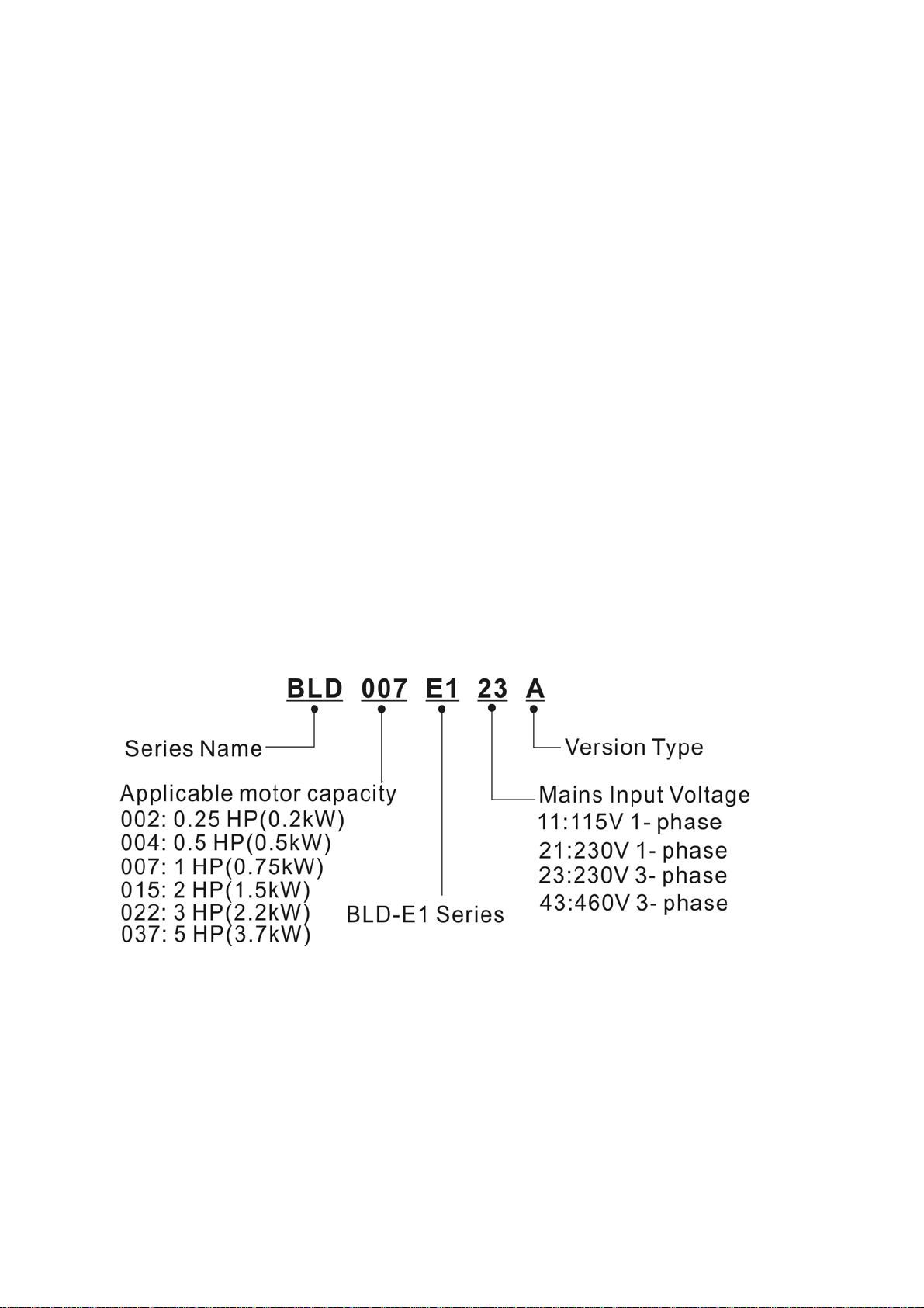
1.1.2 Model Explanation
1-2 Revision May 2009, 00DE, V0.50
Page 10
Chapter 1 Introduction| BLD-E1 Series
1
4
T
A
1.1.3 Series Num b er Explanation
9
007E 123
230V 3-phase 1HP(0.75kW)
If the nameplate information does not correspond to your purchase order or if there are
any problems, please contact your distributor.
0
1
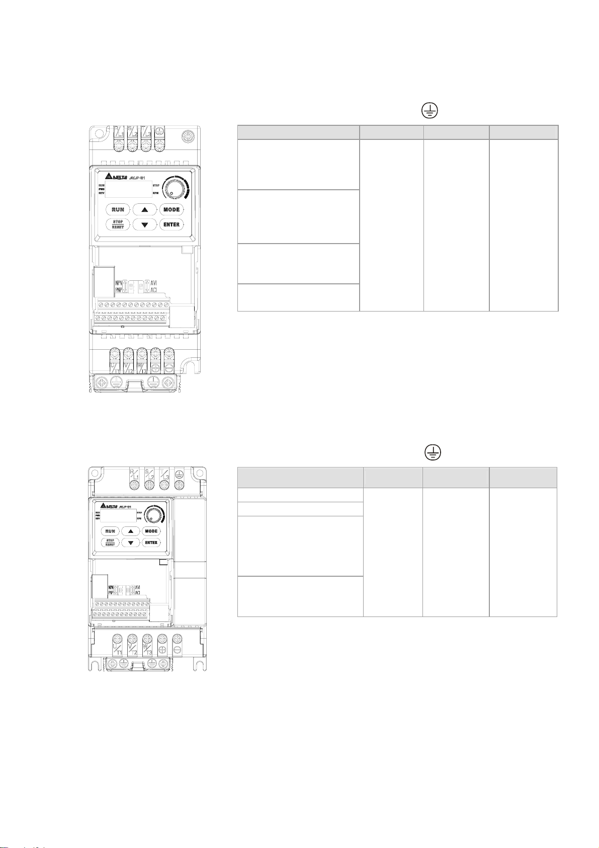
1.1.4 Drive Frames and Appearances
0.25-2HP/0.2-1.5kW (Frame A)
000
Production number
Production week
Production year 2009
Prod uction factory
T: Taoyuan, W: Wujiang
Model
Input terminals
(R/L1, S/L2, T/L3 )
1-5HP/0.75-3.7kW (Frame B)
Dig ital keypa d
Cont rol board cover
Output terminals
(U/T1, V/T2, W/T3)
Input terminals
(R/L1, S/L2, T/L3)
Digital keypad
Case body
Control board cover
Output terminals
(U/T1, V/T2, W/T3)
Revision May 2009, 00DE, V0.50 1-3
Page 11
Chapter 1 Introduction|BLD-E1 Series
Internal Structure
Digital keypad
NPN/PNP
ACI/AVI
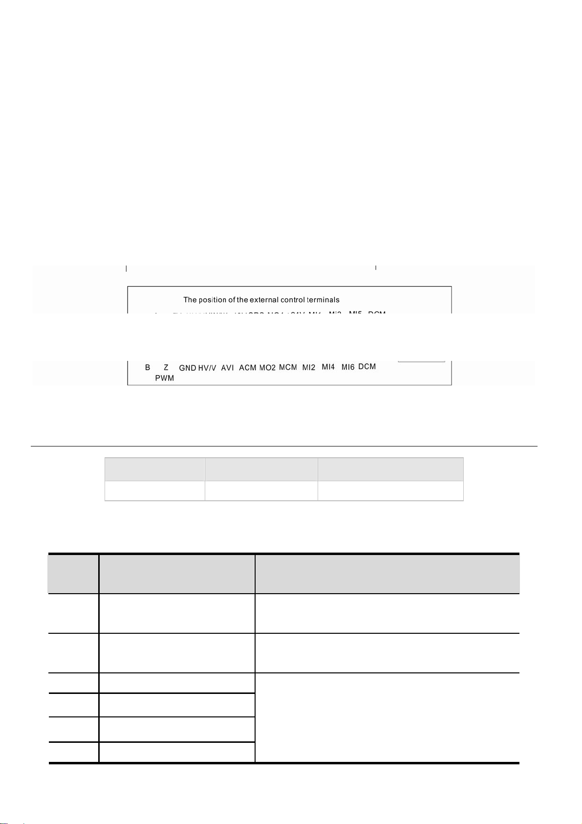
External terminals
RS485 port (RJ-45)
RFI Jumper Location
NOTE
The RFI jumper of frame A and frame B is beside the input terminals (R/L1, S/L2, T/L3) as circled in
above picture and can be removed by loosening the screws.
Frame Power range Models
BLD002E111A/121A/123A, BLD004E111A/121A/123A/
A
B
0.25-2hp (0.2-1.5kW)
1-5hp (0.75-3.7kW)
143 A, BLD007E121A/123A/143A, BLD015E123A/143A
BLD007E111A , BLD015E121A, BLD022E121A /123A/
143A, BLD037E123A/143A
1-4 Revision May 2009, 00DE, V0.50
Page 12

Chapter 1 Introduction| BLD-E1 Series
RFI Jumper
RFI Jumper: The brushless DC motor drive may emit the electrical noise. The EMI(electromagnetic
interference with standard Y capacity) is used to suppress the interference (Radio Frequency
Interference) on the power line. As the leakage current will be increased after using with EMI, user
can cut off the RFI when reducing the leakage current is required.
Main power isolated from earth:
If the brushless DC motor drive is supplied from an isolated power (IT power), the RFI jumper must
be cut off. Then the RFI capacities (filter capacitors) will be disconnected from ground to prevent
circuit damage (according to IEC 61800-3) and reduce earth leakage current.
CAUTION!
1. After applying power to the brushless DC motor drive, do not cut off the RFI jumper. Therefore,
please make sure that main power has been switched off before cutting the RFI jumper.
2. The gap discharge may occur when the transient voltage is higher than 1,000V. Besides,
electro-magnetic compatibility of the brushless DC motor drives will be lower after cutting the
RFI jumper.
3. Do NOT cut the RFI jumper when main power is connected to earth.
4. The RFI jumper cannot be cut when Hi-pot tests are performed. The mains power and motor
must be separated if high voltage test is performed and the leakage currents are too high.
5. To prevent drive damage, the RFI jumper connected to ground shall be cut off if the brushless
DC motor drive is installed on an ungrounded power system or a high impedance grounding
(over 30 ohms) power system or a corner grounded TN system.
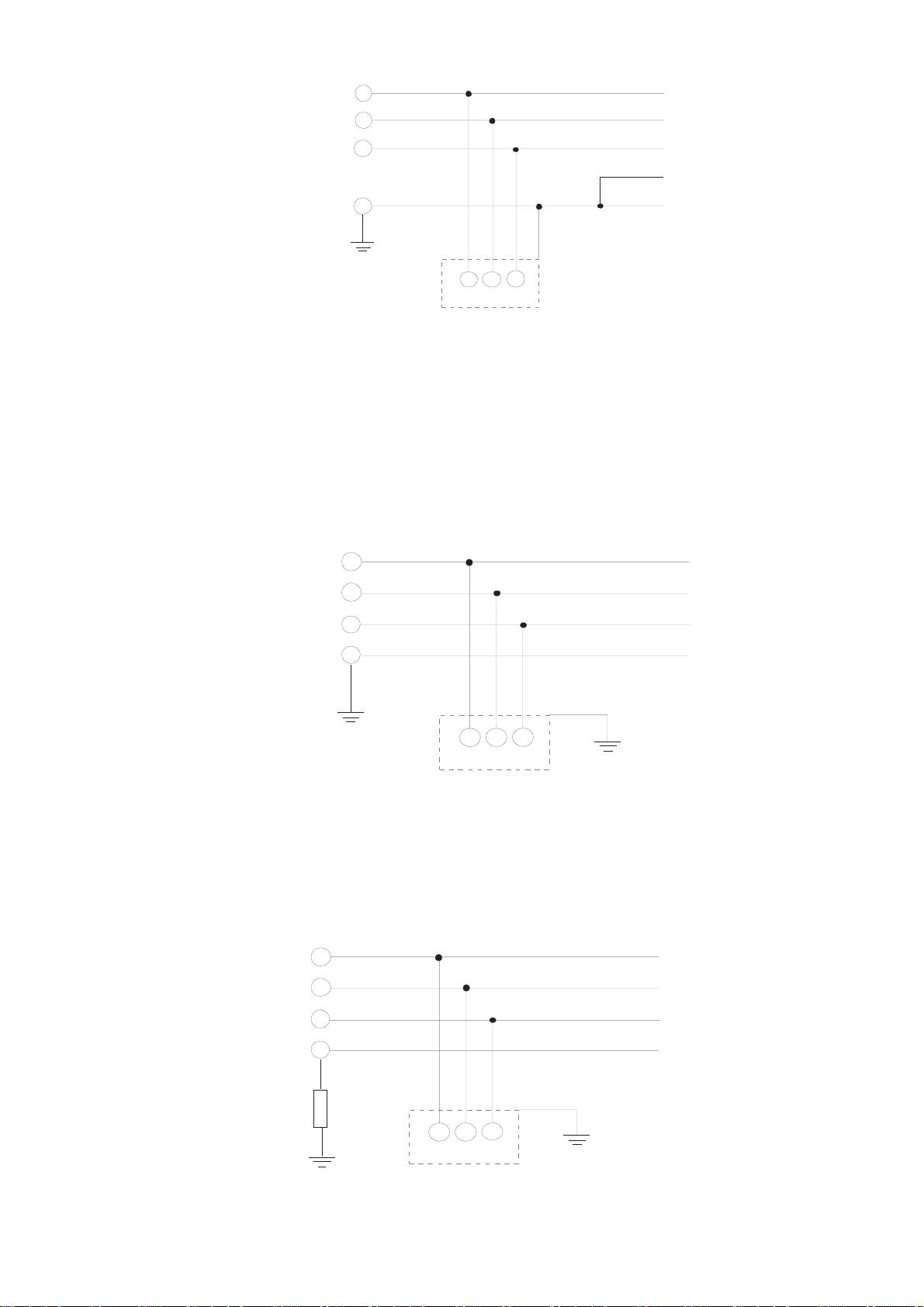
About Grounding System
According to international standard IEC60364, the grounding system can be divided as follows:
1. The first letter: the connection between grounded point and power equipment (generator or
transformer)
T: connect to the same grounded point directly, I: NOT connect to the grounded point
(insulation) or grounded via high-resistance equipment.
2. The second letter: connection method between grounded point and the electrical device being
supplied
T: connect to grounded point, independent of other power supplied grounded point, N:
grounded via the power supply system
3. The third and forth letter: position of grounded conductor
S: neutral and grounded point are disconnection, C: neutral is connected to grounded point in
parallel
Revision May 2009, 00DE, V0.50 1-5
Page 13
Chapter 1 Introduction|BLD-E1 Series
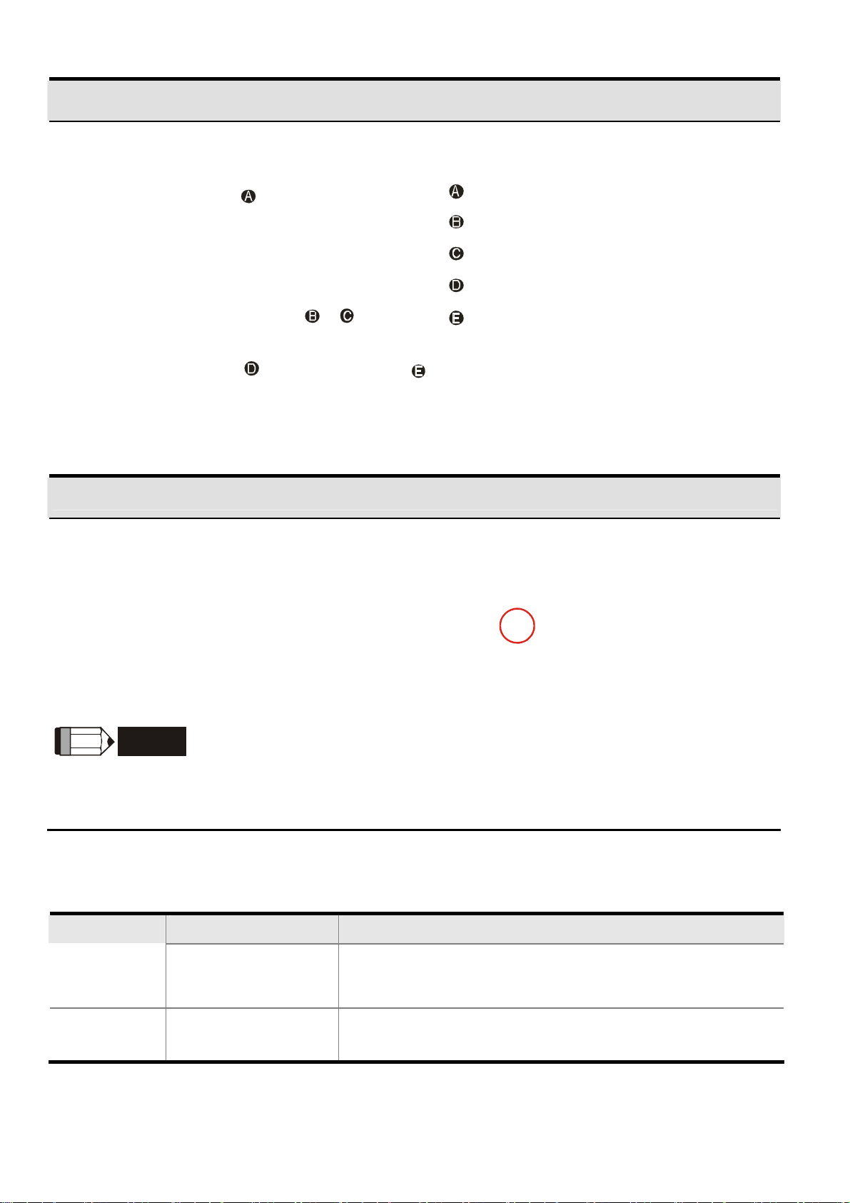
TN-S grounding system:
TN-S is a grounding system with 3-phase, 4-line and PE line. The feature of TN-S system is the
neutral line and protective earth(PE) line have an only common grounding at the neutral point of
transformer. The neutral line (N) is live part and PE line is NOT live part. This grounding system
equips safe and reliable basic potential.
L1
L2
L3
N
PE
L1 L2
TN-S grounding system
L3
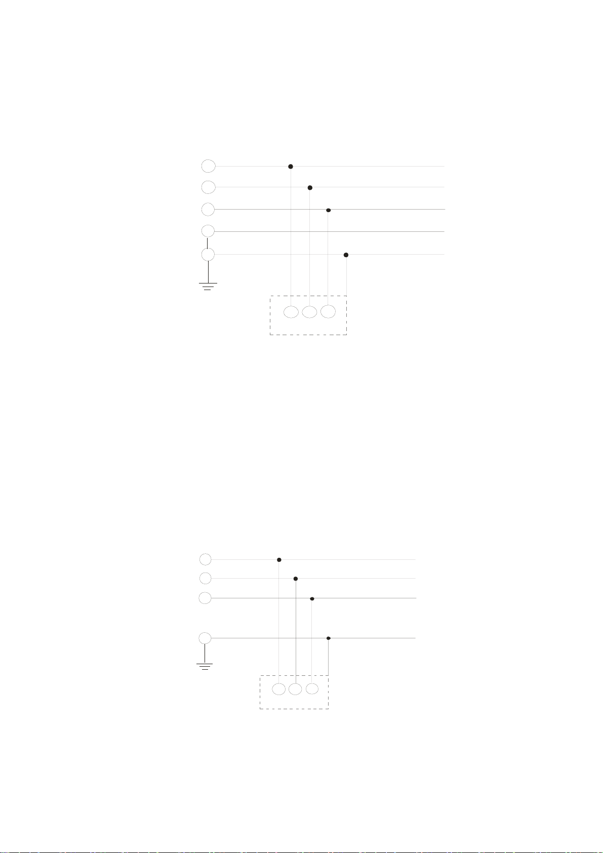
TN-C grounding system:
TN-C grounding system is called 3-phase and 4-line system. This system combines the neutral
line with protective earthing(PE) and is called PEN line. This grounding system is sensitive to
the grounding malfunction with simple wiring but it is only suitable for the occasions with
balanced 3-phase overload. If the high harmonic current caused by the unbalanced current of
PEN line and other power electronic equipment superposes on the neutral line in the normal
situation and makes the neutral line to be live part with unstable current, it will cause unstable
neutral grounding potential. Moreover, it will also make the equipment case connected with
PEN line be live part to result in personal injury and incorrect accurate electronic equipment
operation (can’t get a suitable potential base point).
L1
L2
L3
PEN
L1 L2
TN-C grounding system
L3
TN-C-S grounding system:
TN-C-S grounding system is made up of two grounding systems, including TN-C system and
TN-S system. The connection point of these two systems is at the connection point of N line
and PE line.
1-6 Revision May 2009, 00DE, V0.50
Page 14
Chapter 1 Introduction| BLD-E1 Series
L1
L2
L3
N
PEN
L3
L1 L2
TN-C-S grounding system
TT grounding system:
TT grounding system is usually called 3-phase 4-line grounding system. The feature of TT
grounding system is no electrical connection between the neutral line and protective earthing,
i.e. the grounding of the neutral and PE line is separated. No matter 3-phase load is balanced
or not, the PE line won’t be live part as the neutral line is live part when this system is in normal
operation. When only 1-phase grounding is fault, the fault can’t be stopped immediately due to
the low sensitive of protective earthing and only equipment case may be live part.
PE
L1
L2
L3
N
PE
L1 L2
TT grounding system
IT grounding system:
IT grounding system is a 3-phase 3-line grounding system. The neutral of the system
transformer is not grounded or grounded by the impedance, no neutral line N and protective
earthing is grounded separately. The advantage of this system is that when only one phase is
grounded, it won’t cause greater current in the case and the system will operate normally.
L3
L1
L2
L3
N
PE
L1 L2
IT grounding system
L3
Revision May 2009, 00DE, V0.50 1-7
Page 15

Chapter 1 Introduction|BLD-E1 Series
1.1.5 Remove Instructio n s
Remove Front Cover
Remove Fan
For Frame A and Frame B,
press and hold in the tabs on each side of the
fan and pull the fan up to release.
Step 1 Step 2
1.2 Preparation for Installation and Wiring
1.2.1 Ambient Conditions
Install the brushless DC motor drive in an environment with the following conditions:
-10 ~ +40°C (14~104°F) for UL & cUL
-10 ~ +30 °C (14~86°F)for side-by-side mounting
86 ~ 106 kPa
<1000m
<20Hz: 9.80 m/s2 (1G) max
20 ~ 50Hz: 5.88 m/s2 (0.6G) max
86 ~ 106 kPa
<20Hz: 9.80 m/s2 (1G) max
20 ~ 50Hz: 5.88 m/s2 (0.6G) max
Operation
Storage
Transportation
Pollution
Degree
Air Temperature
Relative Humidity <90%, no condensation allowed
Atmosphere
pressure
Installation Site
Altitude
Vibration
Temperature -20°C ~ +60°C (-4°F ~ 140°F)
Relative Humidity <90%, no condensation allowed
Atmosphere
pressure
Vibration
2: good for a factory type environment.
1-8 Revision May 2009, 00DE, V0.50
Page 16
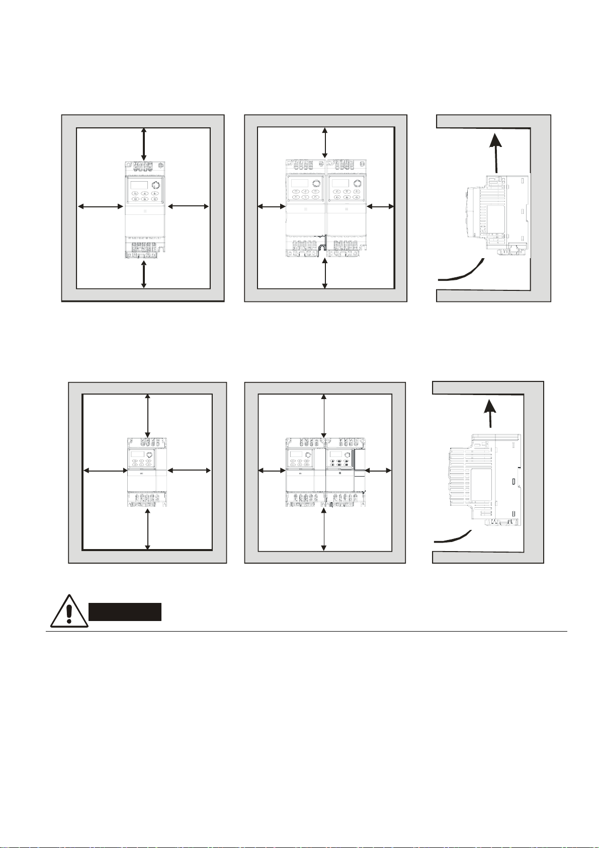
Chapter 1 Introduction| BLD-E1 Series
Minimum Mounting Clearances
Frame A Mounting Clearances
120mm
50mm
50mm
120mm
sing le dr ive
Frame B Mounting Clearances
120mm
Air Flow
50mm
50mm
120mm
side-by-side installation
air flow
150mm
50mm
50mm
150mm
single drive
150mm
50mm
50mm
150mm
side-by-side installation air flow
Air Flow
CAUTION!
1. Operating, storing or transporting the brushless DC motor drive outside these conditions may
cause damage to the brushless DC motor drive.
2. Failure to observe these precautions may void the warranty!
3. Mount the brushless DC motor drive vertically on a flat vertical surface object by screws. Other
directions are not allowed.
4. The brushless DC motor drive will generate heat during operation. Allow sufficient space
around the unit for heat dissipation.
Revision May 2009, 00DE, V0.50 1-9
Page 17
Chapter 1 Introduction|BLD-E1 Series
A
5. The heat sink temperature may rise to 90°C when running. The material on which the brushless
DC motor drive is mounted must be noncombustible and be able to withstand this high
temperature.
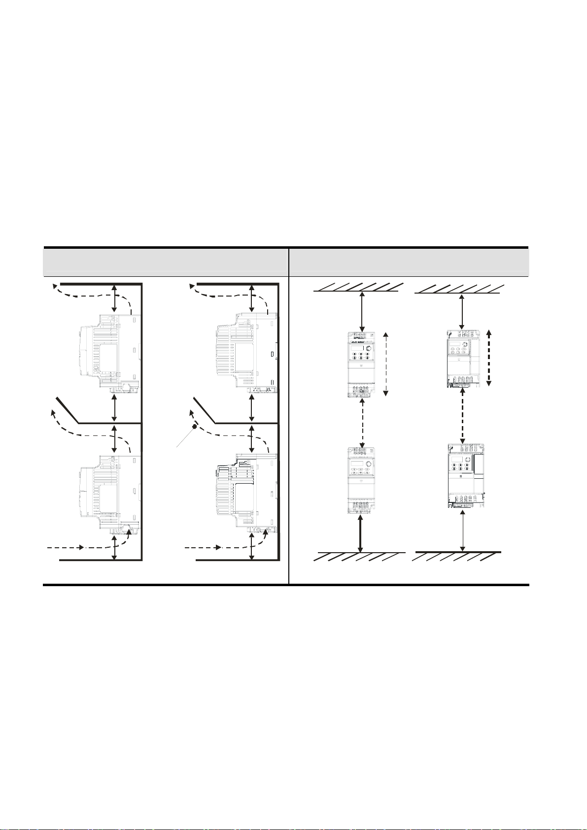
6. When brushless DC motor drive is installed in a confined space (e.g. cabinet), the surrounding
temperature must be within 10 ~ 40°C with good ventilation. DO NOT install the brushless DC
motor drive in a space with bad ventilation.
7. When installing multiple brushless DC motor drives in the same cabinet, they should be
adjacent in a row with enough space in-between. When installing one brushless DC motor drive
below another one, use a metal separation between the brushless DC motor drives to prevent
mutual heating.
Installation with Metal Separation Installation without Metal Separation
120mm
120mm
120mm
120mm
Frame
air flow
150mm
150mm
150mm
150mm
Frame B
120mm
A
120mm
Frame A
150mm
A
Frame B
B
B
150mm
1.2.2 DC-bus Sharing: Connecting the DC-bus of the Brushless DC motor
drive in Parallel
1. The brushless DC motor drives can absorb mutual voltage that generated to DC bus when
deceleration.
2. Enhance brake function and stabilize the voltage of the DC bus.
3. Only the same capacity and same power system can be connected in parallel.
4. The 5 drives should be in same power system, e.g. if the input voltage is 220V, the 5 brushless
DC motor drives connected in parallel must also be 220V.
1-10 Revision May 2009, 00DE, V0.50
Page 18

Chapter 1 Introduction| BLD-E1 Series
NOTE
Prevent fiber particles, scraps of paper, dust, metal particles from adhering to the heatsink.
The material on which the brushless DC motor is mounted must be noncombustible and be able to
withstand the high temperature to prevent fire accidents.
The parallel connection of multiple drives is NOT for 115V models.
Revision May 2009, 00DE, V0.50 1-11
Page 19
Chapter 1 Introduction|BLD-E1 Series
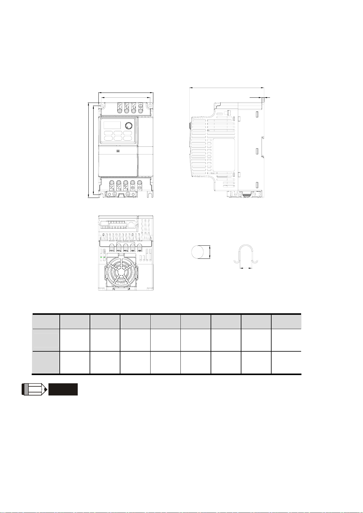
1.3 Dimensions
(Dimensions are in millimeter and [inch])
Frame A
W
W1
H
H1
D
D1
S1
S2
Frame W W1 H H1 D D1 S1 S2
A
B
Frame A:
72.0
[2.83]
100.0
[3.94]
NOTE
BLD002E111A/121A/123A, BLD004E111A/121A/123A/143A, BLD007E121A/123A/143A,
59.0
[2.32]
89.0
[3.50]
174.0
[6.86]
174.0
[6.85]
151.6
[5.97]
162.9
[6.42]
136.1
[5.36]
136.0
[5.36]
4.0
[0.16]
4.0
[0.16]
5.4
[0.21]
5.9
[0.23]
BLD015E123A/143A
5.4
[0.21]
5.4
[0.21]
Frame B:
BLD007E111A , BLD015E121A, BLD022E121A /123A/143A, BLD037E123A/143A
1-12 Revision May 2009, 00DE, V0.50
Page 20

Chapter 2 Installation and Wiring
After removing the cover of input/output terminals and control terminals, check if terminals are clear.
Be sure to observe the following precautions when wiring.
CAUTION!
1. Make sure that power is only applied to the R/L1, S/L2, T/L3 terminals. Failure to comply
may result in damage to the equipment. The voltage and current should lie within the
range as indicated on the nameplate.
2. All the units must be grounded directly to a common ground terminal to prevent lightning
strike or electric shock and also for decreasing the noise interference.
3. Please make sure to fasten the screw of the main circuit terminals to prevent sparks
which is made by the loose screws due to vibration.
DANGER!
1. A charge may still remain in the DC bus capacitors with hazardous voltages even if the power
has been turned off. To prevent personal injury, please ensure that the power is turned off and
wait ten minutes for the capacitors to discharge to safe voltage levels before opening the
brushless DC motor drive.
2. Only qualified personnel familiar with brushless DC motor drives is allowed to perform
installation, wiring and commissioning.
3. Make sure that the power is off before doing any wiring to prevent electric shock.
CAUTION!
1. Use wire gauges that comply with the local regulations during wiring.
2. Check following items after finishing the wiring:
A. Are all connections correct?
B. No loose wires?
C. No short-circuits between terminals or to ground?
Revision May 2009, 00DE, V0.50 2-1
Page 21

Chapter 2 Installation and Wiring| BLD-E1 Series
2.1 Wiring
There are main circuit and control circuit for the wiring of the brushless DC motor. Users must
connect wires according to the circuit diagrams on the following pages.
Figure 1 for models of BLD-E1 Series
BLD002E111A/121A, BLD004E111A/121A, BLD007E111A/121A, BLD015E121A, BLD022E121A
2-2 Revision May 2009, 00DE, V0.50
Page 22
Chapter 2 Installation and Wiring| BLD-E1 Series
Figure 2 for models of BLD-E1 Series
BLD002E123A, BLD004E123A/143A, BLD007E123A/143A, BLD015E123A/143A,
BLD022E123A/143A, BLD037E123A/143A
Revision May 2009, 00DE, V0.50 2-3
Page 23
Chapter 2 Installation and Wiring| BLD-E1 Series
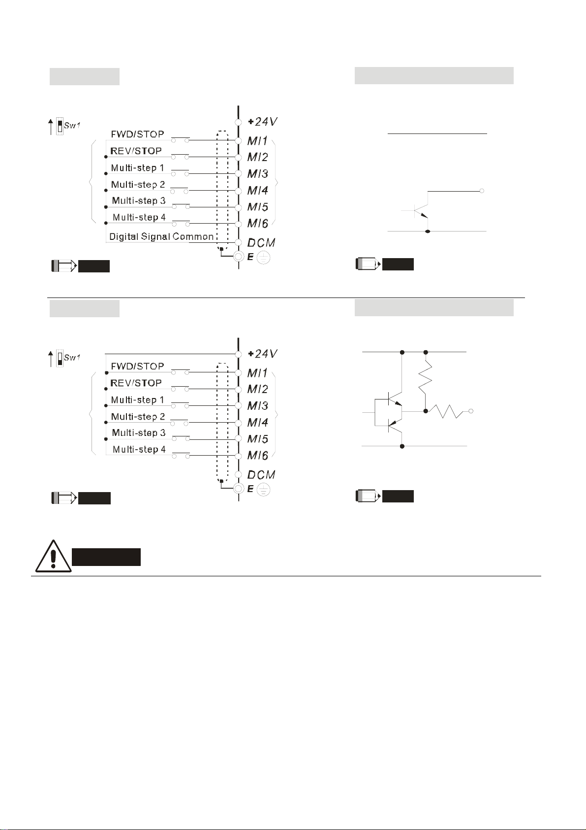
Figure 3 Wiring for NPN mode and PNP mode
NPN M o d e
Applicable Output Signal
Factory setting is NPN
NPN
PNP
Factory
setting
NOTE
Don't ap ply mains voltage into ab ove terminals.
PNP Mod e
Factory setting is PNP
NPN
PNP
Multi-function
input terminals
Open collector output
VCC
O/P
0V
NOTE
It needs to connect O/P to multi-function
input termi nals for norma l operation.
Applicable Output Signal
Complementary outp ut
VCC
Factory
setting
NOTE
Don't ap ply mains voltage into ab ove terminals.
Multi-function
input terminals
NOTE
It needs to connect O/P to multi-function
input termi nals for norma l operation.
O/P
0V
CAUTION!
1. The wiring of main circuit and control circuit should be separated to prevent erroneous actions.
2. Please use shield wire for the control wiring and not to expose the peeled-off net in front of the
terminal.
3. Please use the shield wire or tube for the power wiring and ground the two ends of the shield
wire or tube.
4. Damaged insulation of wiring may cause personal injury or damage to circuits/equipment if it
comes in contact with high voltage.
5. The brushless DC motor drive, motor and wiring may cause interference. To prevent the
equipment damage, please take care of the erroneous actions of the surrounding sensors and
the equipment.
2-4 Revision May 2009, 00DE, V0.50
Page 24
Chapter 2 Installation and Wiring| BLD-E1 Series
6. With long motor cables between the brushless DC motor drive and motor, high capacitive
switching current peaks can cause over-current, high leakage current or lower current readout
accuracy. To prevent this, the motor cable should be less than 20m for 3.7kW models and
below. And the cable should be less than 50m for 5.5kW models and above. For longer motor
cables use an AC output reactor.
7. The brushless DC motor drive, electric welding machine and the greater horsepower motor
should be grounded separately.
8. Use ground leads that comply with local regulations.
9. No brake resistor is built in the BLD-E1 series, it can install brake resistor for those occasions
that use higher load inertia or frequent start/stop. Refer to Appendix B for details.
10. To prevent the lightening strike and electric shock, the metal grounding wire of electric
equipment should be thick, short and connect to the specific ground terminal of the variable
frequency system.
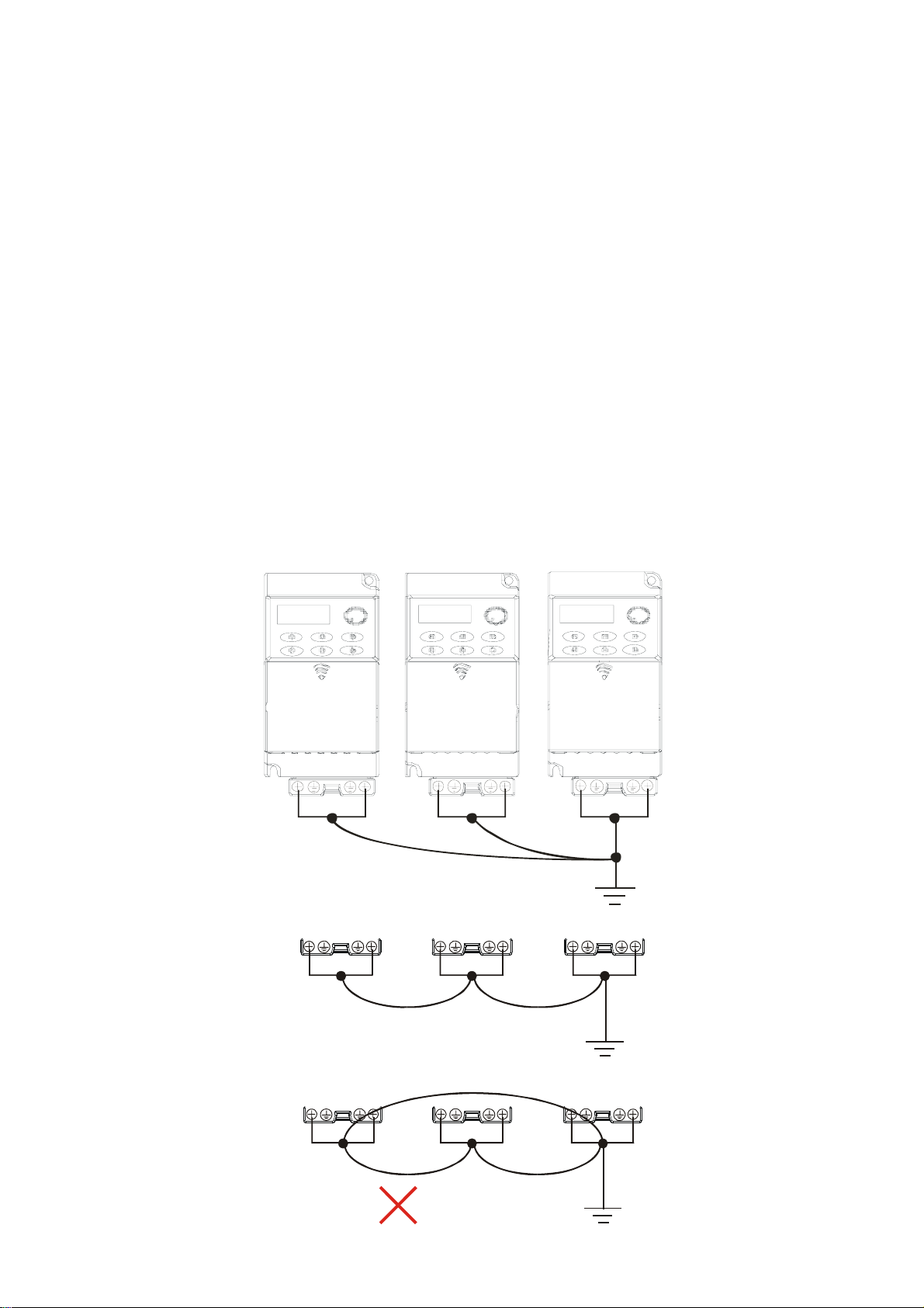
11. Multiple BLD-E1 units can be installed in one location. All the units should be grounded directly
to a common ground terminal, as shown in the figure below. Ensure there are no ground
loops.
Excellent
Good
Not allowed
Revision May 2009, 00DE, V0.50 2-5
Page 25
Chapter 2 Installation and Wiring| BLD-E1 Series
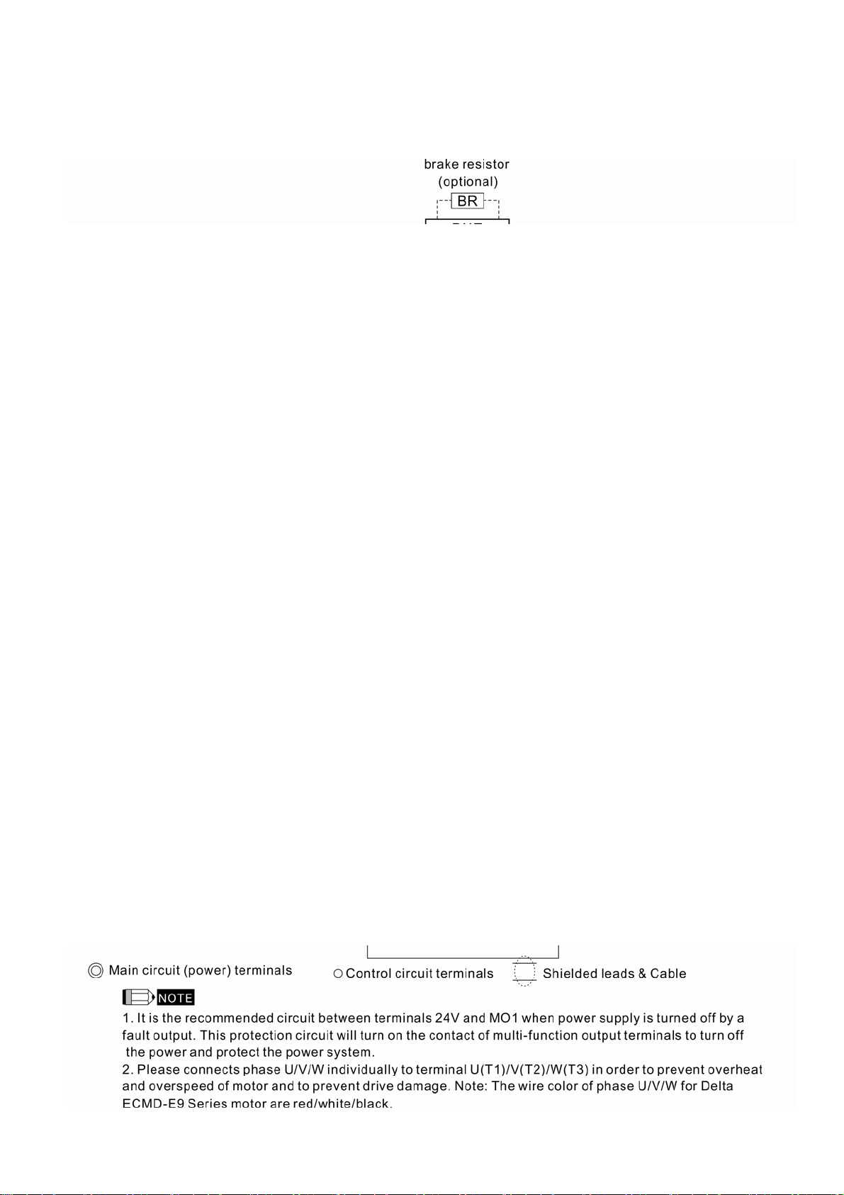
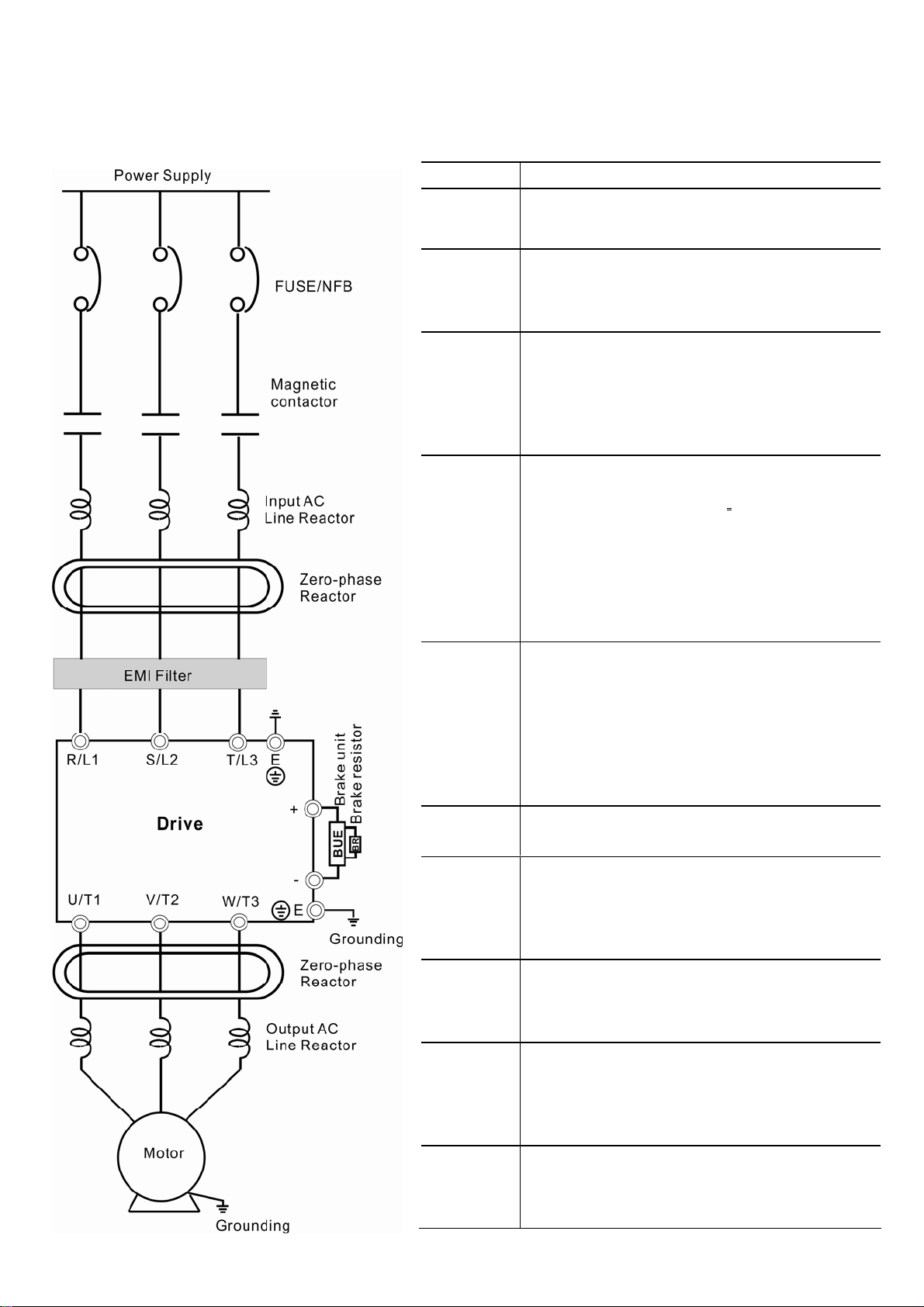
2.2 External Wiring
Items Explanations
Power
supply
Fuse/NFB
(Optional)
Magnetic
contactor
(Optional)
Input AC
Line
Reactor
(Optional)
Zero-phase
Reactor
(Ferrite
Core
Common
Choke)
(Optional)
EMI filter
Driver
Brake
resistor
and Brake
unit
Output AC
Line
Reactor
Grounding
Please follow the specific power supply
requirements shown in Appendix A.
There may be an inrush current during
power up. Please check the chart of
Appendix B and select the correct fuse with
rated current. Use of an NFB is optional.
Do NOT run/stop brushless DC motor drives
by turning the magnetic contactor ON/OFF,
as it will reduce the usage life of drive. If you
still need to run/stop drives by turning the
magnetic contactor ON/OFF, it is
recommended to do so only ONCE per hour.
Used to improve the input power factor, to
reduce harmonics and provide protection
from AC line disturbances.
switching spikes and short interruptions). AC
line reactor should be installed when the
power supply capacity is 500kVA or more or
advanced capacity is activated .The wiring
distance should be
appendix B for details.
Zero phase reactors are used to reduce
radio noise especially when audio equipment
is installed near the brushless DC motor
drive. Effective for noise reduction on both
the input and output sides. Attenuation
quality is good for a wide range from AM
band to 10MHz. Appendix B specifies the
zero phase reactor. (RF220X00A)
To reduce electromagnetic interference. It is
built in 230V 1-phase and 460V models.
The surrounding temperature should be
within the specification (refer to chapter 1) to
prevent from reducing the drive’s usage life.
Please wire according to chapter 2 wiring,
wrong wire may cause damage.
Used to reduce the deceleration time of the
motor. Please refer to the chart in Appendix
B for specific Brake resistors.
Motor surge voltage amplitude depends on
motor cable length. For applications with
long motor cable (>20m), it is necessary to
install a reactor at the drive output side.
Please refer to the chart in appendix B.
To prevent electric shock due to leakage
current of the drive, the drive and motor
should be grounded. Please refer to
specification of main circuit terminal.
≤
(surges,
10m. Refer to
2-6 Revision May 2009, 00DE, V0.50
Page 26
Chapter 2 Installation and Wiring| BLD-E1 Series
2.3 Main Circuit
2.3.1 Main Circuit Connection
Terminal Symbol Explanat ion of Terminal Function
R/L1, S/L2, T/L3
U/T1, V/T2, W/T3
+, -
E
Input terminals of commercial power (1-phase/3-phase)
Output terminals of brushless DC motor drive for connecting
brushless DC motor. Wire: U/T1 (Red); V/T2 (White); W/T3 (Black)
Connections for External Brake unit (BUE series)
Earth connection, please comply with local regulations.
CAUTION!
Mains power terminals (R/L1, S/L2, T/L3)
DO NOT apply 1-phase power to 3-phase models. It is unnecessary to consider phase-
sequence of these mains power terminals (R/L1, S/L2, T/L3).
To connect a no fuse switch between 3-phase AC input power and main circuit terminals
(R/L1, S/L2, T/L3) is necessary. It is recommended to add a magnetic contactor (MC) in the
power input wiring to cut off power quickly and reduce malfunction when activating the
protection function of brushless DC motor drives. Both ends of the MC should have an R-C
surge absorber.
Please make sure to fasten the screw of the main circuit terminals to prevent sparks which is
made by the loose screws due to vibration.
Please use voltage and current within the regulation shown in Appendix A.
Revision May 2009, 00DE, V0.50 2-7
Page 27

Chapter 2 Installation and Wiring| BLD-E1 Series
When using a general GFCI (Ground Fault Circuit Interrupter), select a current sensor
with sensitivity of 200mA or above, and not less than 0.1-second operation time to avoid
nuisance tripping. For the specific GFCI of the brushless DC motor drive, please select a
current sensor with sensitivity of 30mA or above.
Output terminals for main circuit (U, V, W)
The factory setting of the operation direction is forward running.
When it needs to install the filter at the output side of terminals U/T1, V/T2, W/T3 on the
brushless DC motor drive. Please use inductance filter. Do not use advanced capacitors
or L-C (Inductance-Capacitance) or R-C (Resistance-Capacitance), unless approved by
Delta.
DO NOT connect advanced capacitors or surge absorbers at the output terminals of
brushless DC motor drives.
Use well-insulated motor, suitable for drive operation.
When using a general GFCI (Ground Fault Circuit Interrupter), select a current sensor
with sensitivity of 200mA or above, and not less than 0.1-second operation time to avoid
nuisance tripping. For the specific GFCI of the brushless DC motor drive, please select a
current sensor with sensitivity of 30mA or above.
Terminals [+, -] for connecting brake resistor
Connect a brake resistor or brake unit in applications with frequent decelerations, short
deceleration time, insufficient brake torque or requiring increased brake torque.
When using external brake unit, please connect it to the terminals [+, -]. Please do NOT
connect brake resistors to terminals [+, -] directly, as it may cause damage.
All BLD-E1 series don’t have a built-in brake chopper. Please connect an external
optional brake unit (BUE-series) and brake resistor.
When not used, please leave the terminals [+, -] open.
2-8 Revision May 2009, 00DE, V0.50
Page 28
Chapter 2 Installation and Wiring| BLD-E1 Series
2.3.2 Main Circuit Terminals
Frame A
Main circuit terminals:
R/L1, S/L2, T/L3, U/T1, V/T2, W/T3,
Models Wire Torque Wire type
BLD002E111A
BLD002E121A
BLD002E123A
BLD004E111A
BLD004E121A
BLD004E123A
BLD004E143A
BLD007E121A
BLD007E123A
BLD007E143A
BLD015E123A
BLD015E143A
12-18
AWG (3.3-
0.8mm
2
)
, +, -
14-16
kgf-cm
(12-14
in-lbf)
Stranded
copper
Only,
75℃
Frame B
Main circuit terminals:
R/L1, S/L2, T/L3, U/T1, V/T2, W/T3,
Models Wire Torque Wire type
BLD007E111A
BLD015E121A
BLD022E121A
BLD022E123A
BLD022E143A
BLD037E123A
BLD037E143A
8-18
AWG.
(8.3-
0.8mm
2
)
, +/B1, B2, -
16-19
kgf-cm
(14-17
in-lbf)
Stranded
copper
Only,
75℃
Revision May 2009, 00DE, V0.50 2-9
Page 29
Chapter 2 Installation and Wiring| BLD-E1 Series
2.4 Control Terminals
Specification Torque Wire
Terminal A, B 2 kgf-cm (2 in-lbf) 16-24 AWG (1.3-0.2mm2)
Terminal symbols and functions
Terminal
Terminal Function
Symbol
MI1 Forward-Stop command
Factory Settings (NPN mode)
ON: Connect to DCM
ON: forward running
OFF: Ramp to stop
MI2 Reverse-Stop command
MI3 Multi-function Input 3
MI4 Multi-function Input 4
MI5 Multi-function Input 5
MI6 Multi-function Input 6
2-10 Revision May 2009, 00DE, V0.50
ON: reverse running
OFF: Ramp to stop
Refer to Pr.04-05 to Pr.04-08 for programming the
Multi-function Inputs.
ON: the activation current is 16mA.
OFF: leakage current tolerance is 10μA.
Page 30
Chapter 2 Installation and Wiring| BLD-E1 Series
Terminal
Factory Settings (NPN mode)
Terminal Function
Symbol
ON: Connect to DCM
+24V DC Voltage Source +24VDC, 20mA
DCM Digital Signal Common Common for digital inputs
HU/U Reserved
HV/V Reserved
HW/W Reserved
Sending PG signals to the drive, e.g. activation,
A PG feedback signal contact 1
operation, speed control etc.
Sending PG signals to the drive, e.g. activation,
B PG feedback signal contact 2
operation, speed control etc.
PG feedback signal contact
Sending PMW signals to the drive to activate at
Z/PWM
PWM
the origin position.
SPO Reserved
+5V Encoder Power Supply
GND Feedback Signal Common
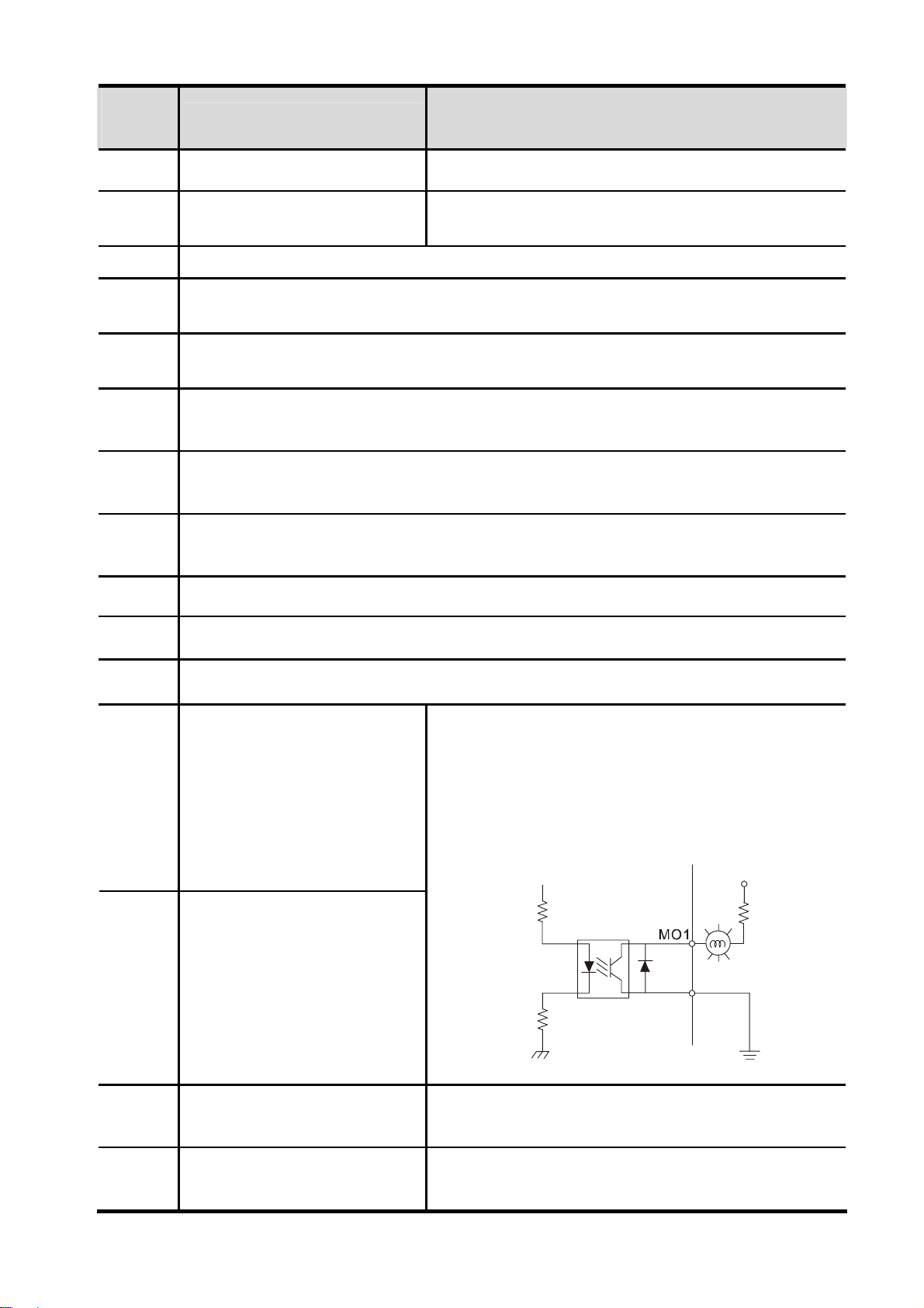
Multi-function Output 1
(Photocoupler)
The brushless DC motor monitors all kinds of
signal, such as during operation, speed attained
and overload indication, by the open collector
MO1
output. Please refer to Pr.02-13, Pr.02-14 for more
details.
Multi-function Output 2
(Photocoupler)
MO2
Max:
+5V
MCM
internal circuit
48VDC/50mA
MCM
Max 48Vdc 50mA
(Photocoupler)
Power supply for analog frequency setting +10VDC
+10V Potentiometer power supply
3mA (variable resistor 3~5kΩ)
Revision May 2009, 00DE, V0.50 2-11
Multi-function output common
Page 31

Chapter 2 Installation and Wiring| BLD-E1 Series
A
A
ACMA
Terminal
Symbol
AVI
ACI
Terminal Function
Analog voltage Input
+10V
VI
CM
internal circuit
Analog current Input
CI
DC
Factory Settings (NPN mode)
ON: Connect to DCM
Impedance: 20kΩ
Resolution: 10 bits
Range: 0 ~ 10VDC =
0 ~ Max. Output Speed (Pr.01-00)
Impedance: 250Ω/100kΩ
Resolution: 10 bits
Range: 4 ~ 20mA =
0 ~ Max. Output Speed(Pr.01-00)
internal circuit
Analog control signal
ACM
Common for AVI and ACI
(common)
NOTE: Control signal wiring size: 18 AWG (0.75 mm
2
) with shielded wire
Analog inputs (AVI, ACI, ACM)
Analog input signals are easily affected by external noise. Use shielded wiring and keep it
as short as possible (<20m) with proper grounding. If the noise is inductive, connecting
the shield to terminal ACM can bring improvement.
If the analog input signals are affected by noise from the brushless DC motor drive,
please connect a capacitor and ferrite core as indicated in the following diagrams:
AVI/ACI
C
ACM
ferrite core
wind each wires 3 times or more around the core
2-12 Revision May 2009, 00DE, V0.50
Page 32

Chapter 2 Installation and Wiring| BLD-E1 Series
Digital inputs (MI1~MI6, DCM)
When using contacts to control the digital inputs, please use high quality components to
avoid contact bounce.
Digital outputs (MO1, MO2, MCM)
Make sure to connect the digital outputs to the right polarity, see wiring diagrams.
When connecting a relay to the digital outputs, connect a surge absorber or fly-back diode
across the coil and check the polarity.
Revision May 2009, 00DE, V0.50 2-13
Page 33

Chapter 2 Installation and Wiring| BLD-E1 Series
This page intentionally left blank
2-14 Revision May 2009, 00DE, V0.50
Page 34

Chapter 3 Keypad and Start Up
3.1 Keypad
3.2 Operation Method
3.3 Trial Run
Make sure that the wiring is correct. In particular, check that the
output terminals U/T1, V/T2, W/T3 are NOT connected to power
Verify that no other equipment is connected to the motor.
Do NOT operate the brushless DC motor drive with humid hands.
Check if it displays 2000.0 on the digital keypad after power is
It should be stopped when fault occurs during running and refer to
and that the drive is well grounded.
applied.
“Fault Code Information and Maintenance” for solution. Please do
NOT touch output terminals U, V, W when power is still applied to
L1/R, L2/S, L3/T even when the brushless DC motor drive has
stopped. It may cause electric shock if touching the output
terminals U, V, W.
Revision May 2009, 00DE, V0.50 3-1
Page 35

Chapter 3 Keypad and Start Up| BLD-E1 Series
3.1 Keypad
1
3
2
4
7
Status Display
1
Display t he driver's operation status.
2
LED Display
In dicat e spee d, volta ge, cu rre nt and
user defined units.
Potentiometer
3
For maste r sp eed set ti ng
4
RUN Key
Start operation
.
5
6
8
5
UP and DOWN Key
Set the parameter number and change the
numerical data, su ch as master speed.
6
MODE
Chan ge between di ff erent disp la y mode.
STOP/RESET
7
Stop operation and reset the drive
af ter fault occurred .
There are five indications on the keypad:
STOP Stop indicator: it will light up when the motor is stop
RUN RUN indicator: it will light up when the motor is running
FWD Forward indicator: it will light up when the motor runs in forward direction
REV Reverse indicator: it will light up when the motor runs in reverse direction
RPM Speed indicator: it will light up when the speed is setting or outputting
3-2 Revision May 2009, 00DE, V0.50
Page 36

Chapter 3 Keypad and Start Up| BLD-E1 Series
Display Message Descriptions
Displays the master speed of the drive and RPM signal blinking.
Displays the actual output speed at terminals U/T1, V/T2, and W/T3.
User defined unit
Displays the output current at terminals U/T1, V/T2, and W/T3.
Displays the brushless DC motor drive forward run status.
Displays the brushless DC motor drive reverse run status.
The counter value (C).
Speed is controlled by current setting.
Speed is controlled by potentiometer and operation is controlled by the
digital keypad.
Displays the selected parameter.
Displays the actual stored value of the selected parameter.
External Fault.
Display “End” for approximately 1 second if input has been accepted and
automatically stored in memory.
Display “Err”, if the input is invalid.
Revision May 2009, 00DE, V0.50 3-3
Page 37

Chapter 3 Keypad and Start Up| BLD-E1 Series
3.1.1 How to Operate the Digital Keypad
The setting values in the following diagram are only example. Please regards the setting value
according to BLD-E1 Series.
3-4 Revision May 2009, 00DE, V0.50
Page 38

Chapter 3 Keypad and Start Up| BLD-E1 Series
Reference Table for the 7-segment LED Display of the Digital Keypad
Digit 0 1 2 3 4 5 6 7 8 9
LED
Display
ASCII 0x30 0x31 0x32 0x33 0x34 0x35 0x36 0x37 0x38 0x39
Digit A b Cc d E F G Hh i Jj
LED
Display
ASCII 0x41 0x62 0x43,0x63 0x64 0x45 0x46 0x47 0x48,0x68 0x69 0x4a,0x6a
Digit K L n o P q r S t Uu
LED
Display
ASCII 0x4b 0x4c 0x6e 0x6f 0x50 0x71 0x72 0x53 0x74 0x55,0x75
Digit v Y Z
LED
Display
ASCII 0x76 0x59 0x5a
Digit
LED
Display
ASCII 0xb0 0xb1 0xb2,0xb3 0xb4 0xb5 0xb6 0xb7 0xb8,0xb9 0xba 0xbb,0xbc
Digit
LED
Display
ASCII 0xbd 0xbe 0xbf 0xc0 0xc1 0xc2 0xc3 0xc4 0xc5 0xc6,0xc7
Digit
LED
Display
ASCII 0xc8 0xc9 0xca
A﹒ b﹒C﹒c﹒ d﹒E
K﹒ L﹒n﹒ o﹒P
v﹒ Y﹒Z﹒
﹒
﹒
F﹒ G
q﹒ r
﹒
H
﹒
S
﹒h﹒
i
﹒
t
﹒
J
﹒
U
﹒j﹒
﹒u﹒
Revision May 2009, 00DE, V0.50 3-5
Page 39

Chapter 3 Keypad and Start Up| BLD-E1 Series
3.2 Operation Method
The operation method can be set via communication and control terminals.
Operation
Method
Operate from the
communication
Operate from the
digital keypad
Frequency Source
When setting communication by the PC, it needs to use VFD-USB01 or
IFD8500 converter to connect to the PC.
Refer to the communication address 2000H and 2101H setting for details.
Operation Command
Source
Figure 3-1
Potentiometer RUN, STOP/RESET
3-6 Revision May 2009, 00DE, V0.50
Page 40

Chapter 3 Keypad and Start Up| BLD-E1 Series
Operation
Method
Operate from
external signal
Frequency Source
FWD/Stop
Factory setting:
NPN Mode
NPN
PNP
* Don't apply the mains voltage directly
to abo v e term in a ls.
Factory setting:
AC I Mode
AVI
ACI
ACI/AVI switch
Factory setting is ACI
Factory
setting
REV/Stop
Multi-step 1
Multi-step 3
Multi-step 4
Digital Signal Common
5K
Analog Signal Common
Multi-step 2
3
2
1
Operation Command
Source
+24V
MI1
MI2
MI3
MI4
Multi-function
input
terminals
MI5
MI6
DCM
E
+10V
Power supply
+10V 20mA
AVI
Master Frequency
0 to 10V 47K
ACI/AVI
4-20mA/0-10V
ACM
E
Figure 3-1
MI3-DCM (Set Pr.04-05=d10)
MI4-DCM (Set Pr.04-06=d11)
MI1-DCM (FWD/STOP)
MI2-DCM(REV/STOP)
Revision May 2009, 00DE, V0.50 3-7
Page 41

Chapter 3 Keypad and Start Up| BLD-E1 Series
3.3 Trial Run
The factory setting of trial run is by the potentiometer, please operate by the following steps.
1. After applying the power, setting the parameter according to the motor type in
parameter group 08. (For Delta’s ECMD-E9 Series of motor, the drive will atuo set the
motor parameter to the default value)
2. Please execute angle detection for the first time operation of Delta ECMD-E9 Motor
and drive. First set 08-00=1 and press RUN, the keypad will show “tun” during the
angle detection. The keypad will return to the main menu after the auto-detection is
finished.
3. Verify that LED display shows 0~3000RPM (depends on the potentiometer position)
with RPM signal blinking and FWD indicator lighted on.
4. Please set potentiometer to a low running speed around 100RPM.
5. Press RUN key for forward running. For ramp to stop, please press STOP/RESET key.
6. To switch to reverse running, press the MODE key and look for FWD page, then press
UP/DOWN key to REV page to finish setting.
7. Check following items:
Check if the direction of motor rotation is correct.
Check if the motor runs steadily without abnormal noise and vibration.
Check if acceleration and deceleration are smooth.
If the results of trial run are normal, please start the formal run.
3-8 Revision May 2009, 00DE, V0.50
Page 42

Chapter 4 Parameters
The BLD-E1 parameters are divided into 14 groups by property for easy setting. In most applications,
the user can finish all parameter settings before start-up without the need for re-adjustment during
operation.
4.1 Summary of Parameter Setting
00:System Parameter
01:Basic Parameters
02:Digital Input/Output Parameters
03:Analog Input/Output Parameter
04:Multi-Step Speed Parameters
05:IM Parameters
06:Protection Parameters
07:Special Parameters
08:PM Parameters
4.2 Description of Parameter Setting
00:System Parameter
01:Basic Parameters
02:Digital Input/Output Parameters
03:Analog Input/Output Parameter
04:Multi-Step Speed Parameters
05:IM Parameters
06:Protection Parameters
07:Special Parameters
08:PM Parameters
09:Communication Parameters
10:Speed Feedback Control Parameters
11 : Advanced Parameters
12:User-defined Parameters
13:View User-defined Parameters
09:Communication Parameters
10:Speed Feedback Control Parameters
11 : Advanced Parameters
12:User-defined Parameters
13:View User-defined Parameters
Revision May 2009, 06EE, V0.50 4-1
Page 43

Chapter 4 ParametersAT |Troubleshooting}| BLD-E1 Series
4.1 Summary of Parameter Settings
Group 00 System Parameters
Parameter Explanation Settings
00.00 Identity Code of
the Brushless DC
Motor Drive
0:115V,1PH,0.2KW,1/4HP
2:115V,1PH,0.4KW,1/2HP
4:115V,1PH,0.7KW,1HP
0:230V,1PH,0.2KW,1/4HP
2:230V,1PH,0.4KW,1/2HP
4:230V,1PH,0.7KW,1HP
6:230V,1PH,1.5KW,2HP
8:230V,1PH,2.2KW,3HP
0:230V,3PH,0.2KW,1/4HP
2:230V,3PH,0.4KW,1/2HP
4:230V,3PH,0.7KW,1HP
6:230V,3PH,1.5KW,2HP
: The parameter can be set during operation.
Factory
Setting
Read-
only
VF VFPG FOCPM
○ ○ ○
8:230V,3PH,2.2KW,3HP
10:230V,3PH,3.7KW,5HP
3:460V,3PH,0.4KW,1/2HP
5:460V,3PH,0.7KW,1HP
7:460V,3PH,1.5KW,2HP
9:460V,3PH,2.2KW,3HP
11:460V,3PH,3.7KW,5HP
00.01 Rated Current
Display of the
Brushless DC
Motor Drive
00.02 Parameter Reset 0:No function
00.03 Start-up Display
Display according to the model
series
10:All parameters are reset to
factory settings
0:Frequency command
Read-
only
0 ○ ○ ○
0 ○ ○ ○
○ ○ ○
Selection
4-2
Revision May 2009, 00DE, V0.50
1:Out put frequency
2:DC BUS voltage
3:Output current
4:output voltage
Page 44

Chapter 4 Parameters| BLD-E1 Series
Parameter Explanation Settings
5:defined by user (Pr.00-04)
00.04 Content of Multi-
function Display
0:Display the output current from
drive to motor
1:Reserved
2:Display actual output frequency
3:Display DC-Bus voltage (U)
4:Display output voltage of U, V,
W (E)
5:Display output power factor
angle (n.)
6:Display output power (kW)
7:Display actual motor speed in
rpm (HU)
Factory
VF VFPG FOCPM
Setting
0 ○ ○ ○
8:Display estimate output torque
(%)
9:Display PG feedback
10:Display the electrical angle of
drive output 11:Display the signal
value % of VR analog input
terminal
12:Display the signal value % of
ACI analog input terminal
13:Display the signal value % of
AVI analog input terminal
14:Reserved
15:Display IGBT temperature ℃
16:Digital input status ON/OFF
17:Digital output status ON/OFF
18:Multi-step speed (S)
19:The corresponding CPU pin
status of digital input
20:The corresponding CPU pin
status of digital output
21~23:Reserved
24:Output AC voltage when
Revision May 2009, 00DE, V0.50 4-3
Page 45

Chapter 4 ParametersAT |Troubleshooting}| BLD-E1 Series
Parameter Explanation Settings
malfunction
25:Output DC voltage when
malfunction
26:Motor frequency when
malfunction
27:Output current when
malfunction
28:Output frequency when
malfunction
29:Frequency command when
malfunction
30:Output power when
malfunction
Factory
VF VFPG FOCPM
Setting
31:Output torque when
malfunction
32:Input terminal status when
malfunction
33:Output terminal status when
malfunction
34:Drive status when malfunction
00.05 Reserved
00.06 Software Version Read-only #.# ○ ○ ○
00.07 Selection of motor
stop method
00.08 Setting of Motor
Running Direction
00.09 Control Method 0:V/Fcontrol
0:decelerate braking to stop
1:coast to stop
0:reverse running allowed
1:reverse running not allowed
2:forward running not allowed
0 ○ ○ ○
0 ○ ○ ○
8 ○ ○ ○
1:V/Fcontrol + Encoder (VFPG)
8:FOC PM Control (FOCPM)
00.10 Speed Unit 0:Hz
3:RPM
00.11 Reserved
00.12 Carrier Frequency 2~15KHz 8 ○ ○ ○
00.13 Auto voltage 0:Enable AVR 0 ○ ○ ○
4-4
Revision May 2009, 00DE, V0.50
3 ○ ○ ○
Page 46

Chapter 4 Parameters| BLD-E1 Series
Parameter Explanation Settings
Regulation (AVR) 1:Disable AVR
2:Disable AVR when deceleration
stop
00.14 Source of
Frequency
Command
00.15 Source of
Operation
Command
0:Digital keypad input
1:RS-485 serial communication
input
2:External analog input
(Pr.03-00~03-02)
3:Digital terminals input
(Pr.04-00~04-15)
0:Digital keypad input
1:External terminal operation
2: RS-485 serial communication
Factory
VF VFPG FOCPM
Setting
2 ○ ○ ○
0 ○ ○ ○
input
Revision May 2009, 00DE, V0.50 4-5
Page 47

Chapter 4 ParametersAT |Troubleshooting}| BLD-E1 Series
r
Group 01 Basic Parameters : The parameter can be set during operation.
Paramete
01.00 Maximum Operation
01.01 1st Output
01.02 1st Output Voltage
01.03 2nd Output
Explanation Settings
120~4000RPM (10~400Hz) 3000
Frequency
0~400.00Hz 60.00 ○ ○ ○
Frequency Setting 1
(Base Frequency/
Rated Motor
Frequency)
230V Series:0.0V~255.0V
Setting 1
(Base Voltage/ Rated
Motor Voltage)
Frequency Setting 1
460V Series:0.0V~510.0V
0~400.00Hz 0.50 ○ ○
Factory
Setting
(250)
220.0
440.0
VF VFPG FOCPM
○ ○ ○
○ ○ ○
01.04 2nd Output Voltage
Setting 1
01.05 3rd Output
Frequency Setting 1
01.06 3rd Output Voltage
Setting 1
01.07 4th Output
Frequency Setting 1
01.08 4th Output Voltage
Setting 1
01.09 Start Frequency 0~4000rpm (0~400.00Hz) 6 (0.5) ○ ○
01.10 Output Frequency
Upper Limit
01.11 Output Frequency
Lower Limit
230V Series:0.0V~255.0V
460V Series:0.0V~510.0V
0~400.00Hz 0.50 ○ ○
230V Series:0.0V~255.0V
460V Series:0.0V~510.0V
0~400.00Hz 0.00 ○ ○
230V Series:0.0V~255.0V
460V Series:0.0V~510.0V
0~4000rpm (0~400.00Hz) 3000
0~4000rpm (0~400.00Hz) 0 (0.00) ○ ○ ○
5.0
10.0
5.0
10.0
0.0
0.0
(250)
○ ○
○ ○
○ ○
○ ○ ○
01.12 Accel Time 1 0.00~600.00 sec 3.00 ○ ○ ○
01.13 Decel Time 1 0.00~600.00 sec 2.00 ○ ○ ○
01.14 Accel Time 2 0.00~600.00 sec 3.00 ○ ○ ○
01.15 Decel Time 2 0.00~600.00 sec 2.00 ○ ○ ○
01.16 Accel Time 3 0.00~600.00 sec 3.00 ○ ○ ○
01.17 Decel Time 3 0.00~600.00 sec 2.00 ○ ○ ○
4-6
Revision May 2009, 00DE, V0.50
Page 48

Chapter 4 Parameters| BLD-E1 Series
Parameter Explanation Settings
VF VFPG FOCPM
Setting
01.18 Accel Time 4 0.00~600.00 sec 3.00 ○ ○ ○
01.19 Decel Time 4 0.00~600.00 sec 2.00 ○ ○ ○
01.20 Reserved
01.21 Reserved
01.22 Reserved
Factory
01.23 Switch Frequency
0~4000rpm (0~400.00Hz) 0 (0.00) ○ ○ ○
between 1st/4th
Accel/decel
01.24 S-curve for
0.0~25.0 sec 0.0 ○ ○ ○
Acceleration
Departure Time S1
01.25 S-curve for
0.0~25.0 sec 0.0 ○ ○ ○
Acceleration Arrival
Time S2
01.26 S-curve for
Deceleration
Departure Time S3
01.27 S-curve for
Deceleration Arrival
Time S4
01.28 Mode Selection when
Frequency < Fmin
01.29 Switch Frequency
form S to S5
01.30 S-curve for
Deceleration Arrival
0.0~25.0 sec 0.0 ○ ○ ○
0.0~25.0 sec 0.0 ○ ○ ○
0:Output waiting
0 ○ ○
1:Zero-speed operation
th
2 : Fmin (4
output frequency
setting)
0~4000rpm (0~400.00Hz) 0 (0.00) ○ ○ ○
0.0~25.0 sec 0.0 ○ ○ ○
Time S5
01.31 Time required for
0.00~600.00 sec 2.00 ○ ○ ○
deceleration to stop
NOTE: With Delta ECMD-E9 Series motor, rated frequency is 2000rpm and maximum frequency is
3000rmp.
Revision May 2009, 00DE, V0.50 4-7
Page 49

Chapter 4 ParametersAT |Troubleshooting}| BLD-E1 Series
r
Group 02 Digital : The parameter can be set during operation.
Paramete
Explanation Settings
02.00 2-wire/3-wire
Operation Control
02.01 Multi-Function
Command Input
(MI3)
Factory
VF VFPG FOCPM
Setting
0:2-wire operation mode1,
FWD/STOP, REV/STOP
0 ○ ○ ○
1:2 –wire mode1, FWD/STOP,
REV/STOP (Line Start Lockout)
2:2-wire mode2, RUN/STOP,
REV/FWD
3:2-wire mode2, RUN/STOP,
REV/FWD (Line Start Lockout)
4:3-wire,
5:3-wire (Line Start Lockout).
0:no function 1 ○ ○ ○
02.02 Multi-Function
Input (MI4)
02.03 Multi-Function
Command Input
(MI5)
02.04 Multi-Function
Command Input
(MI6)
1:Multi-step command 1 2 ○ ○ ○
2:Multi-step command 2 3 ○ ○ ○
3:Multi-step command 3 4 ○ ○ ○
4:Multi-step command 4 ○ ○ ○
5:Reset ○ ○ ○
6:Reserved ○ ○ ○
7:acceleration/deceleration speed
○ ○ ○
inhibit
8:the 1st, 2nd
○ ○ ○
acceleration/deceleration time
selection
9:the 3rd, 4th
○ ○ ○
acceleration/deceleration time
selection
10: EF input (Pr.07-28) ○ ○ ○
11: Reserved ○ ○ ○
4-8
Revision May 2009, 00DE, V0.50
12: Stop output ○ ○ ○
Page 50

Chapter 4 Parameters| BLD-E1 Series
Parameter Explanation Settings Factory
Setting
13~14: Reserved ○ ○ ○
15:Running speed
○ ○ ○
command from VR
16:Running speed
○ ○ ○
command from ACI
17:Running speed
○ ○ ○
command from AVI
18:Emergency Stop
○ ○ ○
(Pr.07-28)
19~26:Reserved ○ ○ ○
27:ASR1/ASR2 Selection ○ ○ ○
28:Emergency stop (EF1)
○ ○ ○
(Motor coasts to stop)
VF VFPG FOCPM
02.05 ~
02.08
Reserved
29~30:Reserved ○ ○ ○
31: High torque bias (by
○ ○ ○
Pr.07-21)
32: Middle torque bias (by
○ ○ ○
Pr.07-22)
33: Low torque bias (by
○ ○ ○
Pr.07-23)
34-37: Reserved ○ ○ ○
38: Disable EEPROM write
○ ○ ○
function
39:Reserved ○ ○ ○
40:Enable drive to
○ ○ ○
function
02.09 Digital Input
0.001~ 30.000 Sec 0.005 ○ ○ ○
Response Time
02.10 Digital Input
0~65535 0 ○ ○ ○
Operation
Direction
02.11 Reserved
Revision May 2009, 00DE, V0.50 4-9
Page 51

Chapter 4 ParametersAT |Troubleshooting}| BLD-E1 Series
Parameter Explanation Settings Factory
Setting
02.12 Reserved
02.13 Multi-function
Output (MO1)
02.14 Multi-function
Output (MO2)
0:No function 41 ○ ○ ○
1: Operation indication 41 ○ ○ ○
2: Operation speed attained ○ ○ ○
3:Desired frequency
attained 1 (Pr. 02-25, 02-
26)
4:Desired frequency
attained 2 (Pr. 02-27, 02-
28)
5: Zero speed (frequency
command)
○ ○ ○
○ ○ ○
○ ○ ○
VF VFPG FOCPM
6: Zero speed with stop
(frequency command)
7: Over torque (OT1) (Pr.
06-05~06-07)
8: Over torque (OT2) (Pr.
06-08~06-10)
9: Drive ready ○ ○ ○
10:Low-voltage Detection
(LV)
11:Malfunction indication ○ ○ ○
12:Reserved ○ ○ ○
13:Overheat warning (Pr.
06-14)
21:Ove voltage warning ○ ○ ○
22:Over-current stall
○ ○ ○
○ ○ ○
○ ○ ○
○ ○ ○
○ ○ ○
○ ○ ○
prevention warning
23:Over-voltage stall
prevention warning
24:Drive operation mode
(Parameter: 00.21=0)
4-10
Revision May 2009, 00DE, V0.50
○ ○ ○
○ ○ ○
Page 52

Chapter 4 Parameters| BLD-E1 Series
Parameter Explanation Settings Factory
Setting
25: Forward running
command
26: Reverse running
command
27~30:Reserved ○ ○ ○
31:Forward running input ○ ○ ○
32:Reverse running input ○ ○ ○
33:Zero-speed (Actual
output frequency)
34:Zero speed with Stop
(actual output frequency)
35~39:Reserved ○ ○ ○
40:Speed attained
○ ○ ○
○ ○ ○
○ ○ ○
○ ○ ○
VF VFPG FOCPM
○ ○ ○
02.23 Multi-output
Direction
02.24 Reserved
02.25 Desired
Frequency
Attained 1
02.26 Width of Desired
Frequency
Attained 1
02.27 Desired
Frequency
Attained 2
02.28 Width of Desired
Frequency
(including zero speed)
0~65535 0 ○ ○ ○
0~4000RPM
(0.00~400.0Hz)
0~4000RPM
(0.00~400.0Hz)
0~4000RPM
(0.00~400.0Hz)
0~4000RPM
(0.00~400.0Hz)
0 (0.00) ○ ○ ○
24 (2.00) ○ ○ ○
0 (0.00) ○ ○ ○
24 (2.00) ○ ○ ○
Attained 2
Revision May 2009, 00DE, V0.50 4-11
Page 53

Chapter 4 ParametersAT |Troubleshooting}| BLD-E1 Series
r
r
r
Group 03: Time Parameters : The parameter can be set during operation.
Paramete
03.00 Analog Input (VR) 0:No function 1 ○ ○ ○
03.01 Analog Input (ACI) 1:Frequency command (torque limit
03.02 Analog Input 3 2:Reserved 0
(AVI) 3: Preload input ○ ○ ○
4~6:Reserved
7: Positive torque limit ○
8: Negative torque limit ○
9: Regenerative torque limit ○
10: Positive/negative torque limit ○
03.03 Analog Input Bias
03.04 Analog Input Bias
Explanation Settings
under TQR control mode)
-100.0~100.0% 0.0 ○ ○ ○
VR
-100.0~100.0% 0.0 ○ ○ ○
Factory
VF VFPG FOCPM
Setting
0 ○ ○ ○
ACI
03.05 Analog Input Bias
AVI
03.06 Positive/negative
Bias Mode VR
03.07 Positive/negative
Bias Mode ACI
(can be set to 0 or
1 only)
03.08 Positive/negative
Bias Mode AVI
03.09 Analog Input Gain
VR
-100.0~100.0% 0.0 ○ ○ ○
0: Zero bias
1: Serve bias as the center, lowe
than bias=bias
2: Serve bias as the center, greate
than bias=bias
3: The absolute value of the bias
voltage while serving as the center
(single polar)
4: Serve bias as the center (single
polar)
0.0~500.0% 100.0 ○ ○ ○
0 ○ ○ ○
0 ○ ○ ○
0 ○ ○ ○
03.10 Analog Input Gain
ACI
03.11 Analog Input Gain
AVI
03.12 Analog Input Delay
Time VR
4-12
Revision May 2009, 00DE, V0.50
0.0~500.0% 100.0 ○ ○ ○
0.0~500.0% 100.0 ○ ○ ○
0.00~2.00 sec 0.05 ○ ○ ○
Page 54

Chapter 4 Parameters| BLD-E1 Series
r
Paramete
03.13 Analog Input Delay
Explanation Settings
0.00~2.00 sec 0.05 ○ ○ ○
Time ACI
03.14 Analog Input Delay
0.00~2.00 sec 0.05 ○ ○ ○
Time AVI
03.15 Loss of the ACI
Signal
0: Disable
1: Continue operation at the last
frequency
2: Decelerate to 0Hz
3: Stop immediately and display E.F.
Factory
VF VFPG FOCPM
Setting
0 ○ ○ ○
Revision May 2009, 00DE, V0.50 4-13
Page 55

Chapter 4 ParametersAT |Troubleshooting}| BLD-E1 Series
Group 04: Multi-Step Speed Parameters
: The parameter can be set during operation.
Parameter Explanation Settings
04.00 Zero Step Speed
Frequency
04.01 1st Step Speed
Frequency
04.02 2nd Step Speed
Frequency
04.03 3rd Step Speed
Frequency
04.04 4th Step Speed
Frequency
04.05 5th Step Speed
Frequency
04.06 6th Step Speed
0~4000RPM (0.00~400.0Hz) 0.00 ○ ○ ○
0~4000RPM (0.00~400.0Hz) 0.00 ○ ○ ○
0~4000RPM (0.00~400.0Hz) 0.00 ○ ○ ○
0~4000RPM (0.00~400.0Hz) 0.00 ○ ○ ○
0~4000RPM (0.00~400.0Hz) 0.00 ○ ○ ○
0~4000RPM (0.00~400.0Hz) 0.00 ○ ○ ○
0~4000RPM (0.00~400.0Hz) 0.00 ○ ○ ○
Factory
VF VFPG FOCPM
Setting
Frequency
04.07 7th Step Speed
Frequency
04.08 8th Step Speed
Frequency
04.09 9th Step Speed
Frequency
04.10 10th Step Speed
Frequency
04.11 11th Step Speed
Frequency
04.12 12th Step Speed
Frequency
04.13 13th Step Speed
Frequency
0~4000RPM (0.00~400.0Hz) 0.00 ○ ○ ○
0~4000RPM (0.00~400.0Hz) 0.00 ○ ○ ○
0~4000RPM (0.00~400.0Hz) 0.00 ○ ○ ○
0~4000RPM (0.00~400.0Hz) 0.00 ○ ○ ○
0~4000RPM (0.00~400.0Hz) 0.00 ○ ○ ○
0~4000RPM (0.00~400.0Hz) 0.00 ○ ○ ○
0~4000RPM (0.00~400.0Hz) 0.00 ○ ○ ○
04.14 14th Step Speed
Frequency
04.15 15th Step Speed
Frequency
0~4000RPM (0.00~400.0Hz) 0.00 ○ ○ ○
0~4000RPM (0.00~400.0Hz) 0.00 ○ ○ ○
4-14
Revision May 2009, 00DE, V0.50
Page 56

Chapter 4 Parameters| BLD-E1 Series
Group 05: IM Parameters : The parameter can be set during operation.
Parameter Explanation Settings
05.18 Accumulative
Motor Operation
Time (min.)
05.19 Accumulative
Motor Operation
Time (day)
05.21 Accumulative
Drive Power-on
Time (min.)
05.22 Accumulative
Drive Power-on
Time (day)
00~1439 0 ○ ○ ○
00~65535 0 ○ ○ ○
00~1439 0 ○ ○ ○
00~65535 0 ○ ○ ○
Factory
VF VFPG FOCPM
Setting
Revision May 2009, 00DE, V0.50 4-15
Page 57

Chapter 4 ParametersAT |Troubleshooting}| BLD-E1 Series
r
Group 6: Protection Parameters
Paramete
06.00 Low Voltage Level 160.0~220.0Vdc
06.01 Phase-loss
06.02 Over-current Stall
06.03 Over-current Stall
06.04 Accel./Decel. Time
Explanation Settings
320.0~440.0Vdc
0: Warn and keep operation
Protection
Prevention during
Acceleration
Prevention during
Operation
1: Warn and ramp to stop
2: Warn and coast to stop
00: disable
00~250%
00: disable
00~250%
0: by current accel/decel time
: The parameter can be set during operation.
Factory
Setting
180.0
360.0
2 ○ ○ ○
00 ○ ○
00 ○ ○
0 ○ ○
VF VFPG FOCPM
○ ○ ○
Selection of Stall
Prevention at
constant speed
06.05 Over-torque
Detection Selection
(OT1)
1: by the 1st accel/decel time
2: by the 2nd accel/decel time
3: by the 3rd accel/decel time
4: by the 4th accel/decel time
5: by auto accel/decel time
0: disable
1: over-torque detection during
constant speed operation, continue
to operate after detection
2: over-torque detection during
constant speed operation, stop
operation after detection
3: over-torque detection during
operation, continue to operate after
detection
0 ○ ○ ○
4: over-torque detection during
operation, stop operation after
detection
06.06 Over-torque
Detection Level
(OT1)
06.07 Over-torque 0.0~60.0 sec 0.1 ○ ○ ○
4-16
Revision May 2009, 00DE, V0.50
10~250% 150 ○ ○ ○
Page 58

Chapter 4 Parameters| BLD-E1 Series
r
Paramete
Explanation Settings
Detection Time
(OT1)
06.08 Over-torque
Detection Selection
(OT2)
0: disable
1: over-torque detection during
constant speed operation, continue
to operate after detection
2: over-torque detection during
constant speed operation, stop
operation after detection
3: over-torque detection during
operation, continue to operate after
detection
4: over-torque detection during
Factory
VF VFPG FOCPM
Setting
0 ○ ○ ○
operation, stop operation after
detection
06.09 Over-torque
10~250% 150 ○ ○ ○
Detection Level
(OT2)
06.10 Over-torque
0.0~60.0 sec 0.1 ○ ○ ○
Detection Time
(OT2)
06.11 Current Limit 0~250% 200 ○ ○ ○
06.12 Electronic Thermal
Relay Selection
0: Inverter motor
1: Standard motor
2 ○ ○ ○
2: Disable
06.13 Electronic Thermal
30.0~600.0 sec 60.0 ○ ○ ○
Characteristic
06.14 Heat Sink Over-
0.0~110.0℃ 85.0 ○ ○ ○
heat (OH) Warning
06.15 Stall Prevention
0~100% (refers to Pr. 06-02, 06-03) 50 ○ ○ ○
Limit Level
06.16 Present Fault
Record
0: No fault
0 ○ ○ ○
06.17 Second Most 1: Over-current during acceleration 0 ○ ○ ○
Revision May 2009, 00DE, V0.50 4-17
Page 59

Chapter 4 ParametersAT |Troubleshooting}| BLD-E1 Series
r
Paramete
06.18 Third Most Recent
06.19 Fourth Most Recent
06.20 Fifth Most Recent
06.21 Sixth Most Recent
Explanation Settings
Recent Fault
Record
Fault Record
Fault Record
Fault Record
Fault Record
(ocA)
2: Over-current during deceleration
(ocd)
3: Over-current during constant
speed (ocn)
4: Ground fault (GFF)
5:Reserved
6: Over-current at stop (ocS)
7: Over-voltage during acceleration
(ovA)
8: Over-voltage during deceleration
Factory
VF VFPG FOCPM
Setting
0 ○ ○ ○
0 ○ ○ ○
0 ○ ○ ○
0 ○ ○ ○
(ovd)
9: Over-voltage during constant
speed (ovn)
10: Over-voltage at stop (ovS)
11: Low-voltage during acceleration
(LvA)
12: Low-voltage during deceleration
(Lvd)
13: Low-voltage during constant
speed (Lvn)
14: Low-voltage at stop (LvS)
15: Phase loss protection (PHL)
16: IGBT heat sink over-heat (oH1)
17:Reserved
18:18: TH1 open loop error (tH1o)
19~20:Reserved
21: over-load (oL) (150% 1Min)
22: Motor over-load (EoL1)
23~25:Reserved
26: over-torque 1 (ot1)
27: over-torque 1 (ot2)
28: Reserved
4-18
Revision May 2009, 00DE, V0.50
Page 60

Chapter 4 Parameters| BLD-E1 Series
r
Paramete
Explanation Settings
Factory
Setting
29: Reserved
30: Memory write-in error (cF1)
31: Memory read-out error (cF2)
32: Isum current detection error (cd0)
33: U-phase current detection error
(cd1)
34: V-phase current detection error
(cd2)
35: W-phase current detection error
(cd3)
36:current detection error (Hd0)
37:current detection error (Hd1)
38:Over-voltage detection error
VF VFPG FOCPM
(Hd2)
39: Ground current detection error
(Hd3)
40: Auto tuning error (AuE)
41:Reserved
42: PG feedback error (PGF1)
43: PG feedback loss (PGF2)
44: PG feedback stall (PGF3)
45: PG slip error (PGF4)
46~47:Reserved
48: Analog current input error (ACE)
49: External fault input (EF)
50: Emergency stop (EF1)
51:B.B. (Base Block)
52~53:Reserved
54: Communication error (cE1)
55: Communication error (cE2)
56: Communication error (cE3)
57: Communication error (cE4)
58: Communication Time-out (cE10)
59: PU time-out (cP10)
Revision May 2009, 00DE, V0.50 4-19
Page 61

Chapter 4 ParametersAT |Troubleshooting}| BLD-E1 Series
r
Group 07 Protection Parameters : The parameter can be set during operation.
Paramete
07.00 Reserved
07.01 Reserved
07.02 DC Brake
07.03 DC Brake Time
07.04 DC Brake Time
07.05 DC Brake
07.06 DC Brake
Explanation Settings
Current Level
during Start-up
during Stopping
Starting
Frequency
Proportional Gain
Factory
VF VFPG FOCPM
Setting
0~100% 0 ○ ○
0.0~60.0 sec 0.0 ○ ○ ○
0.0~60.0 sec 0.0 ○ ○ ○
0~4000rpm (0.00~400.0Hz) 0.00 ○ ○
1~500 50 ○ ○
07.07 ~
07.10
07.11 Fan Control 0: Fan always ON
07.12 Reserved
07.13 Reserved
07.14 Maximum Torque
Reserved
1: 1 minute after brushless DC motor
drive stops, fan will be OFF
2: Brushless DC motor drive runs
and fan ON, brushless DC motor
drive stops and fan OFF
3: Fan ON to run when preliminary
heat sink temperature attained
4: Fan OFF
0~300% 100 ○
Command
1 ○ ○ ○
07.15 ~
07.18
Reserved
4-20
Revision May 2009, 00DE, V0.50
Page 62

Chapter 4 Parameters| BLD-E1 Series
Parameter Explanation Settings Factory
Setting
07.19 Source of
Torque Offset
0: Disable
1: Analog input (Pr.03-
00)
0 ○
2: Torque offset setting
(Pr.07-20)
3: Control by external
terminal ( Pr.07-21 to 07-
23)
07.20 Torque Offset
0.0~100.0% 0.0 ○
Setting
07.21 High Torque
0.0~100.0% 30.0 ○
Offset
07.22 Mid Torque
0.0~100.0% 20.0 ○
VF VFPG FOCPM
Offset
07.23 Low Torque
0.0~100.0% 10.0 ○
Offset
07.24 Forward Motor
0~300% 200 ○
Torque Limit
07.25 Forward
0~300% 200 ○
Regenerative
Torque Limit
07.26 Reverse Motor
0~300% 200 ○
Torque Limit
07.27 Reverse
0~300% 200 ○
Regenerative
Torque Limit
07.28 Emergency
Stop (EF) &
0: Coast to stop
1: By deceleration Time 1
0 ○ ○ ○
Forced Stop
Selection
2: By deceleration Time 2
3: By deceleration Time 3
4: By deceleration Time 4
5: By Pr.01-31
07.29 Time Required
0.000~1.000 sec 0.000 ○
for Decreasing
Torque at Stop
Revision May 2009, 00DE, V0.50 4-21
Page 63

Chapter 4 ParametersAT |Troubleshooting}| BLD-E1 Series
r
Group 08 PM Parameters : The parameter can be set during operation.
Paramete
08.00 Motor Auto
08.01 Full-load Current
08.02 Rated power of
Explanation Settings
0: No function
Tuning
of Motor
Motor
1: Only for the unloaded motor, auto
measure the angle between
magnetic pole and PG origin (Pr.
08.09)
2: For PM parameters
3: Auto measure the angle between
magnetic pole and PG origin
(Pr.08-09)
40~120%)*00.01 Amps #.## ○
0.00~655.35kW #.## ○
Factory
VF VFPG FOCPM
Setting
0 ○
08.03 Rated speed of
Motor (rpm)
08.04 Number of Motor
Poles
08.05 Rs of Motor 0.000~65.535Ω # ○
08.06 Reserved
08.07 Lq of Motor 0.0~6553.5mH # ○
08.08 Back
Electromotive
Force
08.09 Angle between
Magnetic Pole
and PG Origin
08.10 Magnetic Pole
Re-orientation
0~65535 200 ○
2~96 10 ○
0.0~6553.5Vrms # ○
0.0~360.0° 360.0 ○
0: Disable
1: Enable
0 ○
4-22
Revision May 2009, 00DE, V0.50
Page 64

Chapter 4 Parameters| BLD-E1 Series
Group 09 Communication Parameters : The parameter can be set during operation.
Parameter Explanation Settings
09.00 Communication
Address
09.01 Transmission Speed
(Keypad)
09.02 Transmission Fault
Treatment (Keypad)
09.03 Time-out Detection
(Keypad)
09.04 Communication
Protocol (Keypad)
1~254 1 ○ ○ ○
4.8~38.4Kbps 9.6 ○ ○ ○
0: Warn and keep operation
1: Warn and ramp to stop
2: Reserved
3: No action and no display
0.0~100.0 sec 0.0 ○ ○ ○
0: 7N1 (ASCII)
1: 7N2 (ASCII)
2: 7E1 (ASCII)
Factory
VF VFPG FOCPM
Setting
3 ○ ○ ○
1 ○ ○ ○
3: 7O1 (ASCII)
4: 7E2 (ASCII)
5: 7O2 (ASCII)
6: 8N1 (ASCII)
7: 8N2 (ASCII)
8: 8E1 (ASCII)
9: 8O1 (ASCII)
10: 8E2 (ASCII)
11: 8O2 (ASCII)
12: 8N1 (RTU)
13: 8N2 (RTU)
14: 8E1 (RTU)
15: 8O1 (RTU)
16: 8E2 (RTU)
17: 8O2 (RTU)
09.05 Response Delay
Time
0.0~200.0ms 2.0 ○ ○ ○
Revision May 2009, 00DE, V0.50 4-23
Page 65

Chapter 4 ParametersAT |Troubleshooting}| BLD-E1 Series
r
Group 10: Speed Feedback Control Parameters
: The parameter can be set during operation.
Paramete
10.00 Encoder Type 0:No function
10.01 Encoder Pulse 1~25000 256 ○ ○
10.02 Encoder Input Type
Explanation Settings
1:ABZ
2:ABZ+UVW
3:AB+PWM
0:Disable
Setting
0: Disable
1: Phase A leads in a forward run
command and phase B leads in
a reverse run command
2: Phase B leads in a forward
run command and phase A leads
in a reverse run command
Factory
VF VFPG FOCPM
Setting
3 ○ ○
1 ○ ○
10.03 Encoder Feedback
Fault Treatment
(PGF1, PGF2)
10.04 Detection Time for
Encoder Feedback
Fault
10.05 Encoder Stall Level
(PGF3)
10.06 Encoder Stall
Detection Time
10.07 Encoder Slip Range
3:Phase A is a pulse input and
phase B is a direction input.
(L=reverse direction, H=forward
direction)
0: Warn and keep operation
1: Warn and decelerate to stop
2: Warn and stop operation
0.0~10.0 sec 3.0 ○ ○
0~120% (0:disable) 115 ○ ○
0.0~2.0 sec 0.1 ○ ○
0~50% (0:disable) 50 ○ ○
2 ○
(PGF4)
10.08 Encoder Slip
Detection Time
4-24
Revision May 2009, 00DE, V0.50
0.0~10.0 sec 0.5 ○ ○
Page 66

Chapter 4 Parameters| BLD-E1 Series
r
f
Paramete
10.09 Encoder Stall and Slip
10.10 Mode Selection for
10.11 ASR (Auto Speed
10.12 ASR (Auto Speed
Explanation Settings
Error Treatment
UVW Input
Regulation) Control
(P) of Zero Speed
Regulation) Control (I)
of Zero Speed
Factory
Setting
0: Warn and keep operation
1: Warn and decelerate to stop
2: Warn and stop operation
0: Z signal is at the falling edge
of U-phase
1: Z signal is at the rising edge o
U-phase
0.0~500.0% 100.0 ○ ○ ○
0.000~10.000 sec 0.200 ○ ○ ○
2 ○
0 ○ ○
VF VFPG FOCPM
10.13 ASR (Auto Speed
Regulation) Control
(P) 1
10.14 ASR (Auto Speed
Regulation) Control (I)
1
10.15 ASR (Auto Speed
Regulation) Control
(P) 2
10.16 ASR (Auto Speed
Regulation) Control (I)
2
10.17 ASR 1/ASR2 Switch
Frequency
10.18 ASR Primary Low
0.0~500.0% 100.0 ○ ○ ○
0.000~10.000 sec 0.200 ○ ○ ○
0.0~500.0% 100.0 ○ ○ ○
0.000~10.000 sec 0.200 ○ ○ ○
0~4000RPM (0.00~400.0Hz) 7.00 ○ ○ ○
0.000~0.350 sec 0.008 ○ ○ ○
Pass Filter Gain
10.19 Zero Speed Gain (P) 0~655.00% 80.00 ○
10.20 Zero Speed/ASR1 0~4000RPM (0.00~400.0Hz) 5.00 ○ ○
Revision May 2009, 00DE, V0.50 4-25
Page 67

Chapter 4 ParametersAT |Troubleshooting}| BLD-E1 Series
r
Paramete
10.21 ASR1/ASR2 Width
10.22 Operation Time of
10.23 Filter Time of Zero
Explanation Settings
Width Adjustment
Adjustment
Zero Speed
Speed
Factory
VF VFPG FOCPM
Setting
0~4000RPM (0.00~400.0Hz) 5.00 ○ ○
0.000~65.535 sec 0.250 ○
0.000~65.535 sec 0.004 ○
4-26
Revision May 2009, 00DE, V0.50
Page 68

Chapter 4 Parameters| BLD-E1 Series
r
Group 11: Advanced Parameters : The parameter can be set during operation.
Paramete
Explanation Settings
11.00 System Control bit 7=1:Enable position control
bit 15=0:when power is applied,it
will re-detect the magnetic pole
position
11.01 ~
Reserved
11.05
11.06 Zero-speed
0~40Hz 10 ○
Bandwidth
11.07 Low-speed
0~40Hz 10 ○
Bandwidth
11.08 High-speed
0~40Hz 10 ○
Bandwidth
11.09 ~
Reserved
Factory
VF VFPG FOCPM
Setting
0 ○ ○ ○
11.15
11.16 Memory Address 0X0000~0XFFFF 0 ○ ○ ○
Revision May 2009, 00DE, V0.50 4-27
Page 69

Chapter 4 ParametersAT |Troubleshooting}| BLD-E1 Series
Group 12: User-defined Parameters
(User-defined Parameters: from group 00 to 11) : The parameter can be set during operation.
Parameter Explanation Settings
12.00 Present Fault
Record
12.01 Present Fault
Time of Motor
Operation (min.)
12.02 Present Fault
Time of Motor
Operation (day)
12.03 Frequency
Command at
Present Fault
12.04 Output Frequency
at Preset Fault
0616 Read-only
0632 Read-only
0633 Read-only
2132 Read-only
2133 Read-only
Factory
VF VFPG FOCPM
Setting
○ ○ ○
○ ○ ○
○ ○ ○
○ ○ ○
○ ○ ○
12.05 Output Current at
Present Fault
12.06 Motor Frequency
at Present Fault
12.07 Output Voltage at
Present Fault
12.08 DC-Bus Voltage at
Present Fault
12.09 Output Power at
Present Fault
12.10 Output Torque at
Present Fault
12.11 IGBT Temperature
of Power Module
at Present Fault
2134 Read-only
2135 Read-only
2136 Read-only
2137 Read-only
2138 Read-only
2139 Read-only
2140 Read-only
○ ○ ○
○ ○ ○
○ ○ ○
○ ○ ○
○ ○ ○
○ ○ ○
○ ○ ○
12.12 Multi-function
Terminal Input
Status at Present
Fault
4-28
Revision May 2009, 00DE, V0.50
2141 Read-only
○ ○ ○
Page 70

Chapter 4 Parameters| BLD-E1 Series
Parameter Explanation Settings
12.13 Multi-function
2142 Read-
Terminal
Output Status
at Present
Fault
12.14 Drive Status at
2143 Read-
Present Fault
12.15 Second Most
0617 Read-
Recent Fault
Record
12.16 Second Most
0634 Read-
Recent Fault
Time of Motor
Factory
VF VFPG FOCPM
Setting
○ ○ ○
only
○ ○ ○
only
○ ○ ○
only
○ ○ ○
only
Operation
(min.)
12.17 Second Most
Recent Fault
Time of Motor
Operation
(day)
12.18 Third Most
Recent Fault
Record
12.19 Third Most
Recent Fault
Time of Motor
Operation
(min.)
0635 Read-
only
0618 Read-
only
0636 Read-
only
○ ○ ○
○ ○ ○
○ ○ ○
12.20 Third Most
Recent Fault
0637 Read-
only
○ ○ ○
Time of Motor
Operation
(day)
Revision May 2009, 00DE, V0.50 4-29
Page 71

Chapter 4 ParametersAT |Troubleshooting}| BLD-E1 Series
Parameter Explanation Settings
12.21 Fourth Most
Recent Fault
Record
12.22 Fourth Most
Recent Fault
Time of Motor
Operation
(min.)
12.23 Fourth Most
Recent Fault
0619 Read-
0638 Read-
0639 Read-
Factory
VF VFPG FOCPM
Setting
○ ○ ○
only
○ ○ ○
only
○ ○ ○
only
Time of Motor
Operation
(day)
12.24 Fifth Most
Recent Fault
Record
12.25 Fifth Most
Recent Fault
Time of Motor
Operation
(min.)
12.26 Fifth Most
Recent Fault
Time of Motor
Operation
0620 Read-
only
0640 Read-
only
0641 Read-
only
○ ○ ○
○ ○ ○
○ ○ ○
(day)
12.27 Sixth Most
Recent Fault
Record
12.28 Sixth Most
Recent Fault
Time of Motor
4-30
Revision May 2009, 00DE, V0.50
0621 Read-
only
0642 Read-
only
○ ○ ○
○ ○ ○
Page 72

Chapter 4 Parameters| BLD-E1 Series
Parameter Explanation Settings
Operation
(min.)
12.29 Sixth Most
Recent Fault
Time of Motor
Operation
(day)
12.30 No Factory
Setting
12.31 No Factory
Setting
0643 Read-
○ ○ ○
○ ○ ○
Factory
VF VFPG FOCPM
Setting
○ ○ ○
only
Revision May 2009, 00DE, V0.50 4-31
Page 73

Chapter 4 ParametersAT |Troubleshooting}| BLD-E1 Series
Group 13: View User-defined Parameters
: The parameter can be set during operation.
Parameter Explanation Settings
13.00 ~
13.31
View User-defined
Parameters
Pr. 00-00~11-16
Factory
VF VFPG FOCPM
Setting
○ ○ ○
4-32
Revision May 2009, 00DE, V0.50
Page 74

Chapter 4 Parameters| BLD-E1 Series
4.2 Description of Parameter Settings
Group 00 User Parameters
00-00
Control
mode
00-01
Control
mode
Identity Code of the Brushless DC Motor Drive
VF VFPG FOCPM
Settings Read Only
Rated Current Display of the Brushless DC Motor Drive
VF VFPG FCPM
: This parameter can be set during operation.
Factory setting: Read Only
Factory setting: Read Only
Settings Read Only
Pr. 00-00 determines the drive capacity that is set by the factory. It displays the identity code
of the brushless DC motor drive. The capacity, rated current, rated voltage and the max.
carrier frequency relate to the identity code. Users can use the following table to check how
the rated current, rated voltage and max. carrier frequency of the brushless DC drive
correspond to the identity code.
Pr.00-01 displays the rated current of the brushless DC motor drive. By reading this
parameter the user can check if it is correct for the brushless DC motor drive.
kW 0.2 0.4 0.75 0.4 0.75 1.5 2.2 3.7
HP 0.25 0.5 1.0 0.5 1.0 2.0 3.0 5.0
Pr.00-00
Rated Output
Current (A)
Max. Carrier
Frequency
kW 0.2 0.4 0.75 1.5 2.2 0.2 0.4 0.75 1.5 2.2 3.7
HP 0.25 0.5 1.0 2.0 3.0 0.25 0.5 1.0 2.0 3.0 5.0
Pr.00-00
Rated Output
Current (A)
Max. Carrier
Frequency
115V Series
460V Series
0 2 4 3 5 7 9 11
1.6 2.5 4.2 1.5 2.5 4.2 5.5 8.2
15Hz
230V Series (1-phase) 230V Series (3-phase)
0 2 4 6 8 0 2 4 6 8 10
4.9 6.5 9.7 15.7 24 1.9 2.7 4.9 9.0 15 17.0
15kHz
Revision May 2009, 00DE, V0.50 4-33
Page 75

Chapter 4 ParametersAT |Troubleshooting}| BLD-E1 Series
00-02
Control
mode
Settings 0 No Function
10 All parameters are reset to factory settings
When it is set to 10, all parameters will be reset to factory settings.
00-03
Control
mode
Settings 0 Display the frequency command value. (F)
1 Display the actual output frequency (H)
2 DC BUS voltage (V)
3 Display the output current (A)
4 Output voltage (E)
5 Multifunction display, see Pr.00-04
Parameter Reset
VF VFPG FOCPM
Start-up Display Selection
VF VFPG FOCPM
Factory setting: 0
Factory setting: 0
This parameter determines the start-up display page after power is applied to the drive. User
defined options are displayed according to Pr.00-04.
00-04
Control
mode
Settings 0 Display the output current in A supplied to the motor
1 Reserved
2 Display actual output frequency (H)
3
4
5
6
Content of Multi-Function Display
VF VFPG FOCPM
Display the actual DC BUS voltage in VDC of the
brushless DC motor drive (U)
Display the output voltage in VAC of terminals U, V,
W to the motor (E)
Display the power factor angle in º of terminals U, V,
W to the motor (n.)
Display the output power in kW of terminals U, V
and W to the motor (kW)
Factory setting: 0
7
8
9 Display PG position
4-34
Revision May 2009, 00DE, V0.50
Display the actual motor speed in rpm (enabled
when using with PG card).
Display the estimated value of torque in % as it
relates to current.
Page 76

Chapter 4 Parameters| BLD-E1 Series
00-04
10 Display the electrical angle of drive output
11
12
13
14 Reserved
15 Display the temperature of IGBT in °C.
16 Display digital input status ON/OFF
17 Display digital output status ON/OFF
18 Display multi-step speed
19 The corresponding CPU pin status of digital input
20 The corresponding CPU pin status of digital output
Content of Multi-Function Display
Display the signal of VR analog input terminal in %.
Range 0~10V corresponds to 0~100%.
Display the signal of ACI analog input terminal in %.
Range 4~20mA/0~10V corresponds to 0~100%.
Display the signal of AVI analog input terminal in %.
Range -10V~10V corresponds to 0~100%.
21|
24 Output AC voltage when malfunction
25 Output DC voltage when malfunction
26 Motor frequency when malfunction
27 Output current when malfunction
28 Output frequency when malfunction
29 Frequency command when malfunction
30 Output power when malfunction
31 Output torque when malfunction
32 Input terminal status when malfunction
33 Output terminal status when malfunction
34 Drive status when malfunction
It is used to display the content when LED U is ON. It is helpful for getting the brushless DC
Reserved
23
motor drive’s status by this parameter.
Terminal MI8 MI7 MI6 MI5 MI4 MI3 MI2 MI1 REV FWD
Status 0 0 1 0 0 0 0 1 1 0
Revision May 2009, 00DE, V0.50 4-35
Page 77

Chapter 4 ParametersAT |Troubleshooting}| BLD-E1 Series
0: OFF, 1: ON
MI3: Pr.02-01 is set to 1 (multi-step speed command 1)
MI6: Pr.02-04 is set to 8 (the 1st, 2nd acceleration/deceleration time selection)
If REV, MI2, MI3 and MI6 are ON, the value is 0000 0000 0010 0110B in binary and 0026H in
HEX. At the meanwhile, if Pr.00-04 is set to “16” or “19”, it will display “0026” with LED U is ON
on the keypad KPVL-CC01. The setting 16 is the status of digital input and the setting 19 is the
corresponding CPU pin status of digital input. User can set to 16 to monitor digital input status
and then set to 19 to check if the wire is normal.
Terminal MO2 MO1
Status
0 1
RA: Pr.02-13 is set to 9 (Drive ready).
After applying the power to the brushless DC motor drive, if there is no other abnormal status,
the contact will be ON. At the meanwhile, if Pr.00-04 is set to 17 or 20, it will display 0001 with
LED U is ON on the keypad. The setting 17 is the status of digital output and the setting 20 is
the corresponding CPU pin status of digital output. User can set 17 to monitor the digital
output status and then set to 20 to check if the wire if normal.
00-05
Reserved
00-06
Control
mode
Software Version
VF VFPG FOCPM
Settings Read Only
00-07
Selection of motor stop method
Factory setting: #.##
Control
mode
VF VFPG FOCPM
Factory setting: 0
Settings 0: ramp to stop
1: coast to stop
As the drive receives “stop” command, the stop method will be according to this parameter
setting.
4-36
Revision May 2009, 00DE, V0.50
Page 78

Chapter 4 Parameters| BLD-E1 Series
Ramp to stop: the brushless DC decelerates the motor to Minimum Output Frequency
Pr.01-09 and stops according to the deceleration time set in Pr.01-07.
Coast to stop: the brushless DC drive stops output instantly upon command, and motor free
run until it comes to a complete stop.
If the machinery is turned off, the motor must also be stopped to avoid waste of power and
for safety concern. It is suggested to set the brake ramp to stop with ramping duration
matches machinery characteristics.
As the machinery is turned off, if it is allowed for motor to spin freely or the inertia load is large,
it is suggested to set the motor to coast to stop.
00-08
Control
mode
Settings
Setting of Motor Running Direction
VF VFPG FOCPM
0:reverse running allowed
Factory setting: 0
1:reverse running not allowed
2:forward running not allowed
This parameter prevents the machine damage which caused by fwd/rev motor run error.
00-09
Control
mode
Control Method
VF VFPG FOCPM
Factory Setting: 0
Settings 0 V/f control
1 V/f + Encoder (VFPG)
8 FOC PM control (FOCPM)
Revision May 2009, 00DE, V0.50 4-37
Page 79

Chapter 4 ParametersAT |Troubleshooting}| BLD-E1 Series
This parameter determines the control method of the brushless DC motor drive:
Setting 0: user can design V/f ratio by requirement and control multiple motors simultaneously.
Setting 1: User can use PG card with Encoder to do close-loop speed control.
Setting 8: To increase torque and control speed precisely. (1:1000). This setting is only for
using with permanent magnet motor and others are for induction motor.
00-10
Control
mode
Settings
Speed Unit
VF VFPG FOCPM
0 Hz
3 RPM
Factory Setting: 0
When parameter 00.10=3, the setting of parameter 01.00, .09~01.11, 01.23, 01.29,
02.25~02.28, 04.00~04.15, 07.05, 10.17, 10.20 and 10.21 will adjust according to the
different running speed (RPM).
00-11
Reserved
00-12
Control
mode
Carrier Frequency
VF VFPG FOCPM
Factory setting: 8
Settings 2~15KHz
This parameter determinates the PWM carrier frequency of the brushless DC motor drive.
Carrier
Frequency
2kHz
8kHz
15kHz
Acoustic
Noise
Significant
Minimal
Electromagnetic
Noise or Leakage
Current
Minimal
Significant
Heat
Dissipation
Minimal
Significant
Current
Wave
From the table, we see that the PWM carrier frequency has a significant influence on the
electromagnetic noise, brushless DC motor drive heat dissipation, and motor acoustic noise.
If the ambient noise is greater than motor acoustic noise, lower PWM carrier frequency would
allow better heat dissipation.
Though a higher PWM carrier frequency will provide quiet operation, it is necessary to check
if the wiring system and anti-interference function support this action.
If carrier frequency is higher than default setting and must be lowered but meanwhile overload
has reaches the adjusting limit, then the carrier frequency (Fc) will self-adjust in response to
the ambient temperature and current level.
For example, a 460V series under ambient temperature 40 ℃, carrier frequency 15kHz and
rated output current 55% ; if rated output current is now 87%, in responding to the ambient
4-38
Revision May 2009, 00DE, V0.50
Page 80

Chapter 4 Parameters| BLD-E1 Series
temperature, carrier frequency will be lowered to 10kHz, moreover, overload condition will be adjust,
e.g. Fc= 15kHz, rated output current= 50% * 55% = 82.5% and continues for 1 minute, the carrier
frequency (Fc) will be reduced to the default setting.
Overload Adjusting Graph
The control of maximum running speed differ upon PWM setting, therefore, carrier frequency
setting must be 27 times greater than the actual outputted frequency to attain best speed
control response.
For example, if Pr.00-12 setting is 2K, in order to attain best rotation speed control response,
the max. output frequency must be less than 74.07Hz. When number of motor poles is 5, the
rotation speed is controlled to around 888rpm; in this case, it is recommend to set carrier
frequency to 2K and speed command to 900rpm. When carrier frequency (Pr. 00-12) setting
is 6K or lower, please refer to the following chart for value of carrier frequency and rotation
speed:
Revision May 2009, 00DE, V0.50 4-39
Page 81

Chapter 4 ParametersAT |Troubleshooting}| BLD-E1 Series
2K (Pr. 00-12 = 2) 900rpm
3K (Pr. 00-12 = 3) 1350rpm
4K (Pr. 00-12 = 4) 1800rpm
5K (Pr. 00-12 = 5) 2250rpm
6K (Pr. 00-12 = 6) 2700rpm
Greater than 7K (Pr. 00-12 >7K) 3000rpm
00-13
Control
mode
Auto Voltage Regulation (AVR) Function
VF VFPG FOCPM
Factory setting: 0
Settings 0 Enable AVR
1 Disable AVR
2 Disable AVR when deceleration
It is used to select the AVR mode. AVR is used to regulate the output voltage to the motor.
For example, if V/f curve is set to AC200V/50Hz and the input voltage is from 200 to 264VAC,
the output voltage won’t excess AC200V/50Hz. If the input voltage is from 180 to 200V, the
output voltage to the motor and the input voltage will be in direct proportion.
When setting Pr.00-13 to 1 during ramp to stop and used with auto accel./decel. function, the
the deceleration will be smoother and faster.
00-14
Control
mode
Source of the Master Frequency Command
VF VFPG FOCPM
Factory setting: 2
Settings 0
1
2
3
Digital keypad input
RS-485 serial communication input
External analog input (Pr. 03-00~03-02)
Digital terminals input (Pr.04-00~04-15)
This parameter determines the drive’s master frequency source.
00-15
Control
mode
Settings 0
1
2
4-40
Revision May 2009, 00DE, V0.50
Source of the Operation Command
VF VFPG FOCPM
Digital keypad control
External terminal control
RS-485 serial communication or digital keypad (KPVL-CC01) control
Factory setting: 0
Page 82

Chapter 4 Parameters| BLD-E1 Series
BLE-E1 series is shipped without digital keypad and users can use external terminals or RS-
485 to control the operation command.
When the LED PU is light, the operation command can be controlled by the optional digital
keypad (KPC-CE01). Refer to appendix B for details.
Revision May 2009, 00DE, V0.50 4-41
Page 83

Chapter 4 ParametersAT |Troubleshooting}| BLD-E1 Series
Group 01 Basic Parameters This parameter can be set during operation.
01-00
Control
mode
Maximum Output Frequency
VF VFPG FOCPM
Factory setting: 3000(250)
Settings 120~4000rpm (10~400z)
This parameter determines the brushless DC motor drive’s Maximum Output Frequency. All
the brushless DC motor drive frequency command sources (analog frequency inputs 0 to
+10V and 4 to 20mA) are scaled to correspond to the output frequency range.
01-01
Control
mode
1st Output Frequency Setting
VF VFPG FOCPM
Factory setting: 60.00
Settings 0.00~400.00Hz
It is for the base frequency and motor rated frequency.
This value should be set according to the rated frequency of the motor as indicated on the
motor nameplate. If the motor is 60Hz, the setting should be 60Hz. If the motor is 50Hz, it
should be set to 50Hz.
01-02
Control
mode
1st Output Voltage Setting
VF VFPG FOCPM
Settings 230V series 0.1 to 255.0V Factory Setting: 220.0
460V series 0.1 to 510.0V Factory Setting: 440.0
It is for the base frequency and motor rated frequency.
This value should be set according to the rated voltage of the motor as indicated on the motor
nameplate. If the motor is 220V, the setting should be 220.0. If the motor is 200V, it should be
set to 200.0.
There are many motor types in the market and the power system for each country is also
difference. The economic and convenience method to solve this problem is to install the
brushless DC motor drive. There is no problem to use with the different voltage and frequency
and also can amplify the original characteristic and life of the motor.
4-42
Revision May 2009, 00DE, V0.50
Page 84

Chapter 4 Parameters| BLD-E1 Series
01-03
Control
mode
2nd Output Frequency Setting
VF VFPG
Factory setting: 0.50
Settings 0.00~400.00Hz
01-04
Control
mode
2nd Output Voltage Setting
VF VFPG
Settings 230V series 0.1 to 255.0V Factory Setting: 5.0
460V series 0.1 to 510.0V Factory Setting: 10.0
01-05
Control
mode
3rd Output Frequency Setting
VF VFPG
Factory setting: 0.50
Settings 0.00~400.00Hz
01-06
Control
mode
3rd Output Voltage Setting
VF VFPG
Settings 230V series 0.1 to 255.0V Factory Setting: 5.0
460V series 0.1 to 510.0V Factory Setting: 10.0
01-07
Control
mode
4th Output Frequency Setting
VF VFPG
Settings 0.00~400.00Hz Factory Setting: 0
01-08
Control
mode
4th Output Voltage Setting
VF VFPG
Settings 230V series 0.1 to 255.0V Factory Setting: 0.0
460V series 0.1 to 510.0V Factory Setting: 0.0
V/f curve setting is usually set by the motor’s allowable loading characteristics. Pay special
attention to the motor’s heat dissipation, dynamic balance, and bearing lubricity, if the loading
characteristics exceed the loading limit of the motor.
For the V/f curve setting, it should be Pr.01-01≥ Pr.01-03≥ Pr.01-05≥ Pr.01-07. There is no
limit for the voltage setting, but a high voltage at the low frequency may cause motor damage,
overheat, stall prevention or over-current protection. Therefore, please use the low voltage at
the low frequency to prevent motor damage.
V/F curve would only function as Pr. 00-09= 0 or 1 (under V/F control mode) and Pr. 00-10=0.
Revision May 2009, 00DE, V0.50 4-43
Page 85

Chapter 4 ParametersAT |Troubleshooting}| BLD-E1 Series
V
Voltage
1st Output
Voltage Setting 1
01-02
2nd Output
Voltage Setting 1
01-04
3rd Output
Voltage Setting 1
01-06
4th Output
Volta ge Sett ing 1
01-08
4th Freq.
Output Frequency
01-11
Lower Limit
01-09
Start Freq.
01-10
Frequency output
ranges limitation
01-05 01-03 01-01
3rd Freq.
2nd Freq.
Output Frequency
Upper Limit
1st Freq.
Maximum Output
Frequency
Regular V/f Curve
Special V/f Curve
Frequency
01-0001-07
/f Curve
01-09
Control
mode
Start Frequency
VF VFPG
Factory setting: 6
Settings 0.00~400.00Hz
To distinguish which frequency should be start frequency, it needs to compare the value of
min. output frequency and start frequency. The larger value will be start frequency.
When min. output frequency > start frequency
min. output
frequency
start frequency
start frequency
When start frequency > min. output frequency
min. output
frequency
01-10
Control
mode
Output Frequency Upper Limit
VF VFPG FOCPM
Factory setting: 3000
Settings 0.00~4800rpm
01-11
Control
mode
Output Frequency Lower Limit
VF VFPG FOCPM
Factory setting: 0.00
Settings 0.00~4800rpm
The upper/lower output frequency setting is used to limit the actual output frequency. If the
frequency setting is lower than the start-up frequency, it will run with zero speed. If the
frequency setting is higher than the upper limit, it will runs with the upper limit frequency. If
output frequency lower limit > output frequency upper limit, this function is invalid.
4-44
Revision May 2009, 00DE, V0.50
Page 86

Chapter 4 Parameters| BLD-E1 Series
y
01-12
01-14
01-16
01-18
Control
mode
Accel. Time 1 Factory setting: 3.00
Accel. Time 2 Factory setting: 3.00
Accel. Time 3 Factory setting: 3.00
Accel. Time 4 Factory setting: 3.00
VF VFPG FOCPM
Settings 0.00~600.00 sec
01-13
01-15
01-17
01-19
Control
mode
Decel. Time 1 Factory setting: 2.00
Decel. Time 2 Factory setting: 2.00
Decel. Time 3 Factory setting: 2.00
Decel. Time 4 Factory setting: 2.00
VF VFPG FOCPM
Settings 0.00~600.00 sec
The Acceleration Time is used to determine the time required for the brushless DC motor
drive to ramp from 0Hz to Maximum Output Frequency (Pr.01-00).
The Deceleration Time is used to determine the time require for the brushless DC motor drive
to decelerate from the Maximum Output Frequency (Pr.01-00) down to 0Hz.
The Acceleration/Deceleration Time 1, 2, 3, 4 are selected according to the Multi-function
Input Terminals settings. The factory settings are acceleration time 1 and deceleration time 1.
The larger against torque and inertia torque of the load and the accel./decel. time setting is
less than the necessary value, it will enable torque limit and stall prevention function. When it
happens, actual accel./decel. time will be longer than the action above.
Frequenc
01-00
ax. Outp ut
Frequency
Frequency
Setting
accel. time decel. time
01-12,14,16,18
Accel./Decel. Time
01-13,15,17,19
Time
01-20
0-21
0-22
Revision May 2009, 00DE, V0.50 4-45
Reserved
Reserved
Reserved
Page 87

Chapter 4 ParametersAT |Troubleshooting}| BLD-E1 Series
01-23
Control
mode
Switch Frequency between 1st/4th Accel/decel Factory setting: 0
VF VFPG FOCPM
Settings 0.00~400.00Hz
This parameter selects the frequency point for transition from acceleration/deceleration time 1
to acceleration/deceleration time 4.
The transition from acceleration/deceleration time 1 to acceleration/deceleration time 4, may
also be enabled by the external terminals. The external terminal has priority over Pr. 01-23.
Frequency
1st Acceleration
01-23
1st/4th
Acceleration
/Deceleration
Freq.
Time
4th Acceleration Time
1st Deceleration
Time
4th Deceleration
Time
1st/4th Acceleration/Deceleration Switching
01-24
01-25
01-26
01-27
01-30
Control
mode
S-curve for Acceleration Departure Time S1 Factory setting: 1.00
S-curve for Acceleration Arrival Time S2 Factory setting: 1.00
S-curve for Deceleration Departure Time S3 Factory setting: 1.00
S-curve for Deceleration Arrival Time S4 Factory setting: 1.00
S-curve for Deceleration Arrival Time S5 Factory setting: 1.00
VF VFPG FOCPM
Factory setting: 1.00
Settings 0.00~25.00 sec
01-29
Control
mode
Switch Frequency for S Changes to S5
VF VFPG FOCPM
Factory setting: 0.00
Settings 0.00~4800rpm
It is used to give the smoothest transition between speed changes. The accel./decel. curve
can adjust the S-curve of the accel./decel. When it is enabled, the drive will have different
accel./decel. curve by the accel./decel. time.
The Actual Accel. Time = selected accel. Time + (Pr.01-24 + Pr.01-25)/2
The Actual Decel. Time = selected decel. Time + (Pr.01-26 + Pr.01-27)/2
Parameter 01-29 is used to set the switch frequency between S4 and S5 for smooth stop.
4-46
Revision May 2009, 00DE, V0.50
Page 88

Chapter 4 Parameters| BLD-E1 Series
y
Frequenc
01-25=S2
01-12
accel. time
01-24=S1
01-26=S3
01-28
Control
mode
Mode Selection when Frequency< Fmin
VF VFPG SVC
Settings 0 Output Waiting
1
2
Zero-speed operation
Fmin (4th output frequency setting)
01-13
decel. time
01-27=S4
01-30=S5
Factory setting: 0
01-29
Switch frequency
for S3/S4 changes
to S5
Time
When the Brushless DC motor drive is at 0rpm, it will operate by this parameter.
When it is set to 1 or 2, voltage will be output by Fmin corresponding output voltage(Pr.01-08).
01-31
Control
mode
Deceleration Time when Operating without RUN
Command
VF VFPG FOCPM
Factory setting: 2.00
Settings 0.00~600.00 Sec
The brushless DC motor drive will stop by the setting of this parameter when canceling RUN
command. Refer to the figure in Pr.01-29 for details.
Revision May 2009, 00DE, V0.50 4-47
Page 89

Chapter 4 ParametersAT |Troubleshooting}| BLD-E1 Series
Group 2 Digital Input/Output Parameters This parameter can be set during operation.
02-00
Control
mode
2-wire/3-wire Operation Control
VF VFPG FOCPM
Factory setting: 0
Settings 0 FWD/STOP, REV/STOP
1 FWD/STOP, REV/STOP (Line Start Lockout)
2 RUN/STOP, REV/FWD
3 RUN/STOP, REV/FWD (Line Start Lockout)
4 3-wire
5 3-wire (Line Start Lockout)
Three of the six methods include a “Line Start Lockout” feature. When line start lockout is
enabled, the drive will not run once applying the power. The Line Start Lockout feature
doesn’t guarantee the motor will never start under this condition. It is possible the motor may
be set in motion by a malfunctioning switch.
This parameter is used to control operation from external terminals. There are three different
control modes.
02-00 Control Circuits of the External Terminal
0, 1
2-wire operation control (1)
FWD/STOP
REV/STOP
2, 3
2-wire operation control (2)
RUN/STOP
REV/FWD
4, 5
3-wire operation control
4-48
Revision May 2009, 00DE, V0.50
Page 90

Chapter 4 Parameters| BLD-E1 Series
02-01
Multi-Function Input Command 3 (MI3)
Factory Setting: 1
02-02
Multi-Function Input Command 4 (MI4)
Factory Setting: 2
02-03
Multi-Function Input Command 5 (MI5)
Factory Setting: 3
02-04
Multi-Function Input Command 6 (MI6)
Factory Setting: 4
Settings VF VFPG FOCPM
0:no function ○ ○ ○
1:Multi-step command 1 ○ ○ ○
2:Multi-step command 2 ○ ○ ○
3:Multi-step command 3 ○ ○ ○
4:Multi-step command 4 ○ ○ ○
5:Reset ○ ○ ○
6:Reserved
7:acceleration/deceleration speed inhibit ○ ○ ○
8:the 1st, 2nd acceleration/deceleration time
○ ○ ○
selection
9:the 3rd, 4th acceleration/deceleration time
○ ○ ○
selection
10: EF input (Pr.07-28) ○ ○ ○
11: Reserved
12: Stop output ○ ○ ○
13~14: Reserved
15:Running speed command from VR ○ ○ ○
16:Running speed command from ACI ○ ○ ○
17:Running speed command from AVI ○ ○ ○
18:Emergency Stop (Pr.07-28) ○ ○ ○
19~26:Reserved
27:ASR1/ASR2 Selection ○ ○ ○
28:Emergency stop (EF1) (Motor coasts to stop) ○ ○ ○
29~30:Reserved
31: High torque bias (by Pr.07-21) ○ ○ ○
32: Middle torque bias (by Pr.07-22) ○ ○ ○
Revision May 2009, 00DE, V0.50 4-49
Page 91

Chapter 4 ParametersAT |Troubleshooting}| BLD-E1 Series
Settings VF VFPG FOCPM
33: Low torque bias (by Pr.07-23)
34-37: Reserved
38: Disable EEPROM write function
39:Reserved
40:Enable drive to function
This parameter selects the functions for each multi-function terminal.
If Pr.02-00 is set to 3-wire operation control. Terminal MI1 is for STOP terminal. Therefore,
MI1 is not allowed for any other operation.
Settings Functions Descriptions
0 No Function
Multi-step speed
1
command 1
Multi-step speed
2
command 2
Multi-step speed
3
command 3
15 step speeds could be conducted through the digital
statuses of the 4 terminals, and 17 in total if the master
speed and JOG are included. (Refer to Pr. 04-00~04-15)
○ ○ ○
○ ○ ○
○ ○ ○
Multi-step speed
4
command 4
5 Reset
6 Reserved
Acceleration/deceleration
7
Speed Inhibit
When using communication to control the multi-step
speed, setting 1 to 4 will be invalid.
After the error of the drive is eliminated, use this
terminal to reset the drive.
When this function is enabled, acceleration and
deceleration is stopped and the brushless DC motor
drive starts to accel./decel. from the inhibit point.
4-50
Revision May 2009, 00DE, V0.50
Page 92

Chapter 4 Parameters| BLD-E1 Series
Settings Functions Descriptions
The acceleration/deceleration time of the drive could
be selected from this function or the digital statuses of
the terminals; there are 4 acceleration/deceleration
speeds in total for selection.
st
8
The 1
nd
, 2
acceleration
or deceleration time
Bit 0 Bit 1 Descriptions
selection
0 0 First acceleration/deceleration
time
When output frequency is less
than Pr.01-23 (S witch
Frequency between 1st/4th
Accel/decel), it will output 4
th
rd
, 4
th
9
The 3
or deceleration time
selection
10 EF Input
11 Reserved
12 Stop output
13-14 Reserved
15
Operation speed
command form VR
acceleration
accel/decel time.
nd
0 1 2
1 0 3
1 1 4
accel./decel. time
rd
accel./decel. time
th
accel./decel. time
If the drive receives STOP command, it will decelerate
to stop by Pr.01-31.
External fault input terminal and decelerates by Pr.07-
28. (EF fault will be recorded)
When this function is enabled, the drive output will stop
immediately and the motor is free run. When this
function is disabled, the drive will accelerate to the
frequency setting.
When the source of operation speed command is set to
VR, ACI and AVI at the same time and two or above
terminals are ON, the priority is VR>ACI>AVI.
When this function is enabled, the source of the
frequency will force to be VR.
16
17
Operation speed
command form ACI
Operation speed
command form AVI
18 Emergency Stop
When this function is enabled, the source of the
frequency will force to be ACI.
When this function is enabled, the source of the
frequency will force to be AVI.
When this function is enabled, the drive will ramp to stop
by Pr.07-28 setting.
19-26 Reserved
Revision May 2009, 00DE, V0.50 4-51
Page 93

Chapter 4 ParametersAT |Troubleshooting}| BLD-E1 Series
Settings Functions Descriptions
27 ASR1/ASR2 selection
28
Emergency stop (EF1)
(Motor coasts to stop)
29-30 Reserved
31 High torque bias
32 Middle torque bias
33 Low torque bias
ON: speed will be adjusted by ASR 2 setting.
OFF: speed will be adjusted by ASR 1 setting.
When it is ON, the drive will execute emergency stop
with fault code 50 (EF1)
When Pr.07-19 is set to 3:
31: The high torque bias is according to the Pr.07-21
setting.
32: The middle torque bias is according to the Pr.07-22
setting.
33: The low torque bias is according to the Pr.07-23
setting.
31 32 33 Torque Bias
OFF OFF OFF No
OFF OFF ON 07-23
OFF ON OFF 07-22
02-05
34-37 Reserved
38
Disable write EEPROM
function
39 Reserved
40 Enable drive function
Reserved
OFF ON ON 07-23+07-22
ON OFF OFF 07-21
ON OFF ON 07-21+07-23
ON ON OFF 07-21+07-22
ON ON ON 07-21+07-22+07-23
When this function is enabled, you can’t write into
EEPROM.
When this function is enabled, the drive function can be
executed. This function can be used with multi-function
output (setting Pr.02-11~Pr.02-14 to 15) and (Pr.02-31
and Pr.02-32).
02-06
02-07
02-08
Reserved
Reserved
Reserved
4-52
Revision May 2009, 00DE, V0.50
Page 94

Chapter 4 Parameters| BLD-E1 Series
02-09
Control
mode
Digital Input Response Time
VF VFPG FOCPM
Factory setting: 0.005
Settings 0.001~ 30.000 sec
This parameter is used for digital input terminal signal delay and confirmation. The delay time
is confirmation time to prevent some uncertain interferences that would result in error (except
for the counter input) in the input of the digital terminals (FWD, REV and MI1~6). Under this
condition, confirmation for this parameter could be improved effectively, but the response time
will be somewhat delayed.
02-10
Control
mode
Digital Input Operation Direction
VF VFPG FOCPM
Factory setting: 0
Settings 0 ~ 65535
This parameter is used to set the input signal level and it won’t be affected by the
SINK/SOURCE status.
Bit0 is for FWD terminal, bit1 is for REV terminal and bit2 to bit9 is for MI1 to MI8.
User can change terminal status by communicating.
For example, MI1 is set to 1 (multi-step speed command 1), MI2 is set to 2 (multi-step speed
command 2). Then the forward + 2
need to set Pr.02-10=9 by communication and it can forward with 2
nd
step speed command=1001(binary)=9 (Decimal). Only
nd
step speed. It doesn’t
need to wire any multi-function terminal.
bit5 bit4 bit3 bit2 bit1 bit0
MI6 MI5 MI4 MI3 MI2 MI1
02-11
02-12
Reserved
Reserved
02-13
02-14
Multi-function Output 3 (MO1)
Multi-function Output 4 (MO2)
Factory Setting: 0
Settings VF VFPG FOCPM
0:No function
1: Operation indication
2: Operation speed attained
Revision May 2009, 00DE, V0.50 4-53
○ ○ ○
○ ○ ○
○ ○ ○
Page 95

Chapter 4 ParametersAT |Troubleshooting}| BLD-E1 Series
3:Desired frequency attained 1 (Pr. 02-25, 02-26)
4:Desired frequency attained 2 (Pr. 02-27, 02-28)
5: Zero speed (frequency command)
6: Zero speed with stop (frequency command)
7: Over torque (OT1)
8: Over torque (OT2)
9: Drive ready
10:Low-voltage Detection (LV)
11:Malfunction indication
12:Reserved
13:Overheat warning (Pr. 06-14)
14~16:Reserved
○ ○ ○
○ ○ ○
○ ○ ○
○ ○ ○
○ ○ ○
○ ○ ○
○ ○ ○
○ ○ ○
○ ○ ○
○ ○ ○
○ ○ ○
17:Malfunction indication 1
18~19:Reserved
20:Warning output
21:Ove voltage warning
22:Over-current stall prevention warning
23:Over-voltage stall prevention warning
24:Drive operation mode(Pr. 00-21=0)
25: Forward running command
26: Reverse running command
27~30:Reserved
31:Forward running input
32:Reverse running input
○ ○ ○
○ ○ ○
○ ○ ○
○ ○ ○
○ ○ ○
○ ○ ○
○ ○ ○
○ ○ ○
○ ○ ○
○ ○ ○
33:Zero-speed (Actual output frequency)
34:Zero speed with Stop (actual output frequency)
35~39:Reserved
40:Speed attained (including zero speed)
4-54
Revision May 2009, 00DE, V0.50
○ ○ ○
○ ○ ○
○ ○ ○
Page 96

Chapter 4 Parameters| BLD-E1 Series
Settings Functions Descriptions
0 No Function
1 AC Drive Operational
2 Operation speed attained
Desired Frequency
3
Attained 1 (Pr.02-25, 02-
26)
Desired Frequency
4
Attained 2 (Pr.02-27, 02-
28)
5
6
Zero Speed (frequency
command)
Zero Speed with Stop
(frequency command)
Active when there is an output from the drive or RUN
command is ON.
Active when the brushless DC motor drive reaches the output
frequency setting.
Active when the desired frequency (Pr.02-25, 02-26) is
attained.
Active when the desired frequency (Pr.02-27, 02-28) is
attained.
Active when frequency command =0. (the drive should be at
RUN mode)
Active when frequency command =0 or stop.
Active when detecting over-torque. Refer to Pr.06-05 (over-
7 Over Torque (OT1)
torque detection selection-OT1), Pr.06-06 (over-torque
detection level-OT1) and Pr.06-07 (over-torque detection
time-OT1). (Pr.06-05~06-07)
Active when detecting over-torque. Refer to Pr.06-08 (over-
8 Over Torque (OT2)
torque detection selection-OT2), Pr.06-09 (over-torque
detection level-OT2) and Pr.06-10 (over-torque detection
time-OT2). (Pr.06-08~06-10)
9 Drive Ready
10
User-defined Lowvoltage Detection
11 Malfunction Indication
Active when the drive is ON and no abnormality detected.
Active when the DC Bus voltage is too low. (refer to Pr.06-00
low voltage level)
Active when fault occurs (except Lv stop).
12 Reserved
13 Overheat (Pr.06-14)
Active when IGBT or heat sink overheats to prevent OH turn
off the drive. (refer to Pr.06-14)
14~16 Reserved
17 Malfunction indication 1 Activate after 10ms when fault occurs (except Lv stop).
18~19 Reserved
20 Warning Output
21 Over-voltage Warning
Revision May 2009, 00DE, V0.50 4-55
Active when the warning is detected.
Active when the over-voltage is detected.
Page 97

Chapter 4 ParametersAT |Troubleshooting}| BLD-E1 Series
Settings Functions Descriptions
22
23
24
Over-current Stall
Prevention Warning
Over-voltage Stall
prevention Warning
Operation Mode
Indication
25 Forward Command
26 Reverse Command
27~30 Reserved
31 Forward running input
32
33
34
Reverse running input
Zero Speed (actual
output frequency)
Zero Speed with Stop
(actual output frequency)
Active when the over-current stall prevention is detected.
Active when the over-voltage stall prevention is detected.
Active when the operation command is controlled by external
terminal. (Pr.00-15=1) and PU LED on keypad KPVL-CC01 is
OFF.
Active when the operation direction is forward.
Active when the operation direction is reverse.
Motor forward run (FWD).
Motor Reverse run (REV).
Active when the actual output frequency is 0. (the drive should
be at RUN mode)
Active when the actual output frequency is 0 or Stop. (the
drive should be at RUN mode)
35~39 Reserved
40
Speed Attained
(including zero speed)
02-15
02-16
02-17
02-18
02-19
02-20
02-21
02-22
Reserved
Reserved
Reserved
Reserved
Reserved
Reserved
Reserved
Reserved
02-23
Control
mode
Multi-output Direction
VF VFPG FOCPM
Active when the output frequency reaches frequency setting.
Factory setting: 0
Settings 0 ~ 65535
This parameter is bit setting. If the bit is 1, the multi-function output terminal will be act with
opposite direction. For example, if Pr.02-13 is set to 1 and forward bit is 0, Relay 1 will be ON
4-56
Revision May 2009, 00DE, V0.50
Page 98

Chapter 4 Parameters| BLD-E1 Series
when the drive is running and OFF when the drive is stop; if multi-function output terminal is
set to opposite direction, Relay will be OFF when the drive is running and ON when the drive
is stop.
Bit 1 Bit 0
MO2 MO1
02-24
02-25
Control
mode
02-26
Control
mode
02-27
Control
mode
02-28
Control
mode
Settings 0.00 ~ 4800rpm
Once output frequency reaches desired frequency and the corresponding multi-function
Reserved
Desired Frequency Attained 1
VF VFPG FOCPM
The Width of the Desired Frequency Attained 1
VF VFPG FOCPM
Desired Frequency Attained 2
VF VFPG FOCPM
The Width of the Desired Frequency Attained 2
VF VFPG FOCPM
Factory setting: 0
Factory setting: 24
Factory setting: 0
Factory setting: 24
output terminal is set to 3 or 4 (Pr.02-11~Pr.02-22), this multi-function output terminal will be
ON.
Revision May 2009, 00DE, V0.50 4-57
Page 99

Chapter 4 ParametersAT |Troubleshooting}| BLD-E1 Series
Group 3 Analog Input/Output Parameters This parameter can be set during operation.
03-00
03-01
03-02
0: No function
1: Frequency command (torque limit under TQR
control mode)
2: Reserved
3: Preload input
4-6: Reserved
Analog Input 1 (VR)
Factory Setting: 1
Analog Input 2 (ACI)
Factory Setting: 0
Analog Input 3 (AVI)
Factory Setting: 0
Settings VF VFPG FOCPM
○ ○ ○
○ ○ ○
○ ○ ○
7: Positive torque limit
8: Negative torque limit
9: Regenerative torque limit
10: Positive/negative torque limit
When it is frequency command or TQR speed limit, the corresponding value for 0~±
10V/4~20mA is 0 – max. output frequency(Pr.01-00)
When it is torque command or torque limit, the corresponding value for 0~±10V/4~20mA is
0 – max. output torque (Pr.07-14).
When it is torque compensation, the corresponding value for 0~±10V/4~20mA is 0 – rated
torque.
○
○
○
○
4-58
Revision May 2009, 00DE, V0.50
Page 100

Chapter 4 Parameters| BLD-E1 Series
Positive torque
03-00~0 2=7
03-00~0 2=9
Reg ener ative
torque limit
03-00~02=10
Positive/negat ive torque limit
Positive to rque limit
Rever se
03-00~0 2=10
Positive/negat ive torque limit
03-00~02=8
Negative to rque limit
Neg ative Torq ue
03-00~02=9
Reg ener ative
torque limit
03-03
Control
mode
Settings -100.0~100.0%
It is used to set the corresponding VR voltage of the external analog input 0.
03-04
Analog Input Bias 1 (VR)
VF VFPG FOCPM
Analog Input Bias 1 (ACI)
Factory setting: 0.0
Forward
Control
mode
VF VFPG FOCPM
Factory setting: 0.0
Settings -100.0~100.0%
It is used to set the corresponding ACI voltage of the external analog input 0.
03-05
Control
mode
Analog Input Bias 1 (AVI)
VF VFPG FOCPM
Factory setting: 0.0
Settings -100.0~100.0%
It is used to set the corresponding AVI voltage of the external analog input 0.
The relation between external input voltage/current and setting frequency is equal to -
10~+10V (4-20mA) corresponds to 0~3000rpm.
03-06
Control
mode
Positive/negative Bias Mode (VR)
VF VFPG FOCPM
Factory setting: 0
Revision May 2009, 00DE, V0.50 4-59
 Loading...